PULL-OUT RESISTANCE OF SELF-TAPPING WOOD SCREWS …
130
PULL-OUT RESISTANCE OF SELF-TAPPING WOOD SCREWS WITH CONTINUOUS THREAD by MAIK GEHLOFF Dipl.-Ing. (FH), University of Applied Sciences, Eberswalde, Germany, 2002 A THESIS SUBMITTED IN PARTIAL FULFILLMENT OF THE REQUIREMENTS FOR THE DEGREE OF MASTER OF APPLIED SCIENCE in THE FACULTY OF GRADUATE STUDIES (Forestry) THE UNIVERSITY OF BRITISH COLUMBIA (Vancouver) July 2011 © Maik Gehloff, 2011
Transcript of PULL-OUT RESISTANCE OF SELF-TAPPING WOOD SCREWS …

PULL-OUT RESISTANCE OF SELF-TAPPING WOOD SCREWS
WITH CONTINUOUS THREAD
by
MAIK GEHLOFF
Dipl.-Ing. (FH), University of Applied Sciences, Eberswalde, Germany, 2002
A THESIS SUBMITTED IN PARTIAL FULFILLMENT OF
THE REQUIREMENTS FOR THE DEGREE OF
MASTER OF APPLIED SCIENCE
in
THE FACULTY OF GRADUATE STUDIES
(Forestry)
THE UNIVERSITY OF BRITISH COLUMBIA
(Vancouver)
July 2011
© Maik Gehloff, 2011

ii
ABSTRACT
Over the past centuries the use of timber in structures has seen waves of decline and
rediscovery. Timber structures have evolved from empirical structures using timber
within its natural boundaries in terms of shape, size and length to modern day
engineering design approach using computers and sophisticated numerical models; this
has led to the need of high performance connections in such structures.
With the help of mechanical fasteners the envelope was pushed time and time again,
creating ever stronger connections. However, the capacity of such connections is not only
governed by the mechanical properties of the connectors, but also by the mechanical
properties of the connecting wood members. Researchers have been developing different
methods of reinforcing the inherent weakness of wood, namely the low strength in
tension and compression perpendicular to the grain, as well as the low capacity in
longitudinal shear.
This thesis examines experimentally the pull-out resistance of self-tapping wood screws
with continuous thread, a new type of fastener that can be used as a fastener, but also as
reinforcement considering Canadian major wood species. Utilizing its high withdrawal
capacity and high tensile strength, this type of connector can potentially be used to
transfer internal forces in the wood along the length-axis of the screw instead of loading
the wood in its weak directions.
The results show that self-tapping wood screws (STSs) have a high resistance to pull-out
and are an economical alternative to other reinforcement methods. Besides the superior
capacities of STSs in withdrawal and tensile strength to other methods, they are also very
easy to install since no pre-drilling of holes is required and thus, give an economical
solution to many challenges in engineered timber construction.

iii
TABLE OF CONTENTS
ABSTRACT ........................................................................................................................ ii
TABLE OF CONTENTS ................................................................................................... iii
LIST OF TABLES ............................................................................................................. iv
LIST OF FIGURES ............................................................................................................ v
ACKNOWLEDGEMENTS ............................................................................................. xiii
1. INTRODUCTION ...................................................................................................... 1
1.1. History .................................................................................................................. 1
1.2. Self-tapping wood screws .................................................................................... 7
2. EXPERIMENTAL DESIGN / EQUATIONS .......................................................... 13
2.1. Parameter considerations.................................................................................... 13
2.2. Test setup............................................................................................................ 15
2.3. European code equations .................................................................................... 19
2.4. Equivalency calculations .................................................................................... 22
3. RESULTS / DISCUSSION....................................................................................... 25
3.1. Results ................................................................................................................ 25
3.2. Discussion .......................................................................................................... 36
4. CONCLUSIONS AND RECOMMENDATIONS ................................................... 58
4.1. Conclusions ........................................................................................................ 58
4.2. Recommendations .............................................................................................. 59
BIBLIOGRAPHY ............................................................................................................. 61
APPENDIX – SUPPLEMENTAL MATERIAL .............................................................. 64

iv
LIST OF TABLES
Table 1: Effective embedment depths ............................................................................... 18
Table 2: Average densities ................................................................................................ 25
Table 3: Withdrawal test results for 90° ........................................................................... 26
Table 4: Withdrawal test results for 45° ........................................................................... 29
Table 5: Withdrawal test results for 30° ........................................................................... 32
Table 6: Comparison of test results to code equation predictions for STS ....................... 37

v
LIST OF FIGURES
Figure 1: Development of wood design since 1750............................................................ 2
Figure 2: Knitted glass and aramid fibre fabric (spiral) ...................................................... 4
Figure 3: Transversally reinforced carbon fibre loop ......................................................... 4
Figure 4: Typical load-displacement curve......................................................................... 4
Figure 5: Beam splice using glued-in rods ......................................................................... 6
Figure 6: Screw thread in accordance with DIN 7998 ........................................................ 8
Figure 7: Self-tapping wood screws ................................................................................... 9
Figure 8: Self-tapping wood screw drill-tips ...................................................................... 9
Figure 9: Shank cutter on partially threaded screw ............................................................ 9
Figure 10: STS as embedment and splitting reinforcement .............................................. 11
Figure 11: Test setup for 90º tests ..................................................................................... 15
Figure 12: Test setup for 45º tests ..................................................................................... 16
Figure 13: Test setup for 30º tests ..................................................................................... 16
Figure 14: Transducer to measure deflection .................................................................... 17
Figure 15: Effective embedment depth ............................................................................. 18
Figure 16: Average withdrawal resistance for 6 mm screw @ 90º................................... 27
Figure 17: Average withdrawal resistance for 8 mm screw @ 90º................................... 27
Figure 18: Average withdrawal resistance for 10 mm screw @ 90º................................. 28
Figure 19: Average withdrawal resistance for 6 mm screw @ 45º................................... 30
Figure 20: Average withdrawal resistance for 8 mm screw @ 45º................................... 30
Figure 21: Average withdrawal resistance for 10 mm screw @ 45º................................. 31
Figure 22: Average withdrawal resistance for 6 mm screw @ 30º................................... 33
Figure 23: Average withdrawal resistance for 8 mm screw @ 30º................................... 33

vi
Figure 24: Average withdrawal resistance for 10 mm screw @ 30º................................. 34
Figure 25: Typical screw failure ....................................................................................... 34
Figure 26: Typical load deformation plot ......................................................................... 35
Figure 27: Wood density distribution ............................................................................... 36
Figure 28: Comparison of 6 mm results with DIN 1052:2004-8 predictions @ 90° ........ 39
Figure 29: Comparison of 6 mm results with EC 5 predictions @ 90° ............................ 39
Figure 30: Comparison of 6 mm results with DIN 1052:2004-8 predictions @ 45° ........ 40
Figure 31: Comparison of 6 mm results with EC 5 predictions @ 45° ............................ 40
Figure 32: Comparison of 6 mm results with DIN 1052:2004-8 predictions @ 30° ........ 41
Figure 33: Comparison of 6 mm results with EC 5 predictions @ 30° ............................ 41
Figure 34: Comparison of 8 mm results with DIN 1052:2004-8 predictions @ 90° ........ 42
Figure 35: Comparison of 8 mm results with EC 5 predictions @ 90° ............................ 42
Figure 36: Comparison of 8 mm results with DIN 1052:2004-8 predictions @ 45° ........ 43
Figure 37: Comparison of 8 mm results with EC 5 predictions @ 45° ............................ 43
Figure 38: Comparison of 8 mm results with DIN 1052:2004-8 predictions @ 30° ........ 44
Figure 39: Comparison of 8 mm results with EC 5 predictions @ 30° ............................ 44
Figure 40: Comparison of 10 mm results with DIN 1052:2004-8 predictions @ 90° ...... 45
Figure 41: Comparison of 10 mm results with EC 5 predictions @ 90° .......................... 45
Figure 42: Comparison of 10 mm results with DIN 1052:2004-8 predictions @ 45° ...... 46
Figure 43: Comparison of 10 mm results with EC 5 predictions @ 45° .......................... 46
Figure 44: Comparison of 10 mm results with DIN 1052:2004-8 predictions @ 30° ...... 47
Figure 45: Comparison of 10 mm results with EC 5 predictions @ 30° .......................... 47
Figure 46: Comparison of 6 mm results with DIN 1052:2004-8 adjustments @ 90° ...... 49
Figure 47: Comparison of 6 mm results with EC 5 adjustments @ 90° ........................... 49
vii
Figure 48: Comparison of 6 mm results with DIN 1052:2004-8 adjustments @ 45° ...... 50
Figure 49: Comparison of 6 mm results with EC 5 adjustments @ 45° ........................... 50
Figure 50: Comparison of 6 mm results with DIN 1052:2004-8 adjustments @ 30° ...... 51
Figure 51: Comparison of 6 mm results with EC 5 adjustments @ 30° ........................... 51
Figure 52: Comparison of 8 mm results with DIN 1052:2004-8 adjustments @ 90° ...... 52
Figure 53: Comparison of 8 mm results with EC 5 adjustments @ 90° ........................... 52
Figure 54: Comparison of 8 mm results with DIN 1052:2004-8 adjustments @ 45° ...... 53
Figure 55: Comparison of 8 mm results with EC 5 adjustments @ 45° ........................... 53
Figure 56: Comparison of 8 mm results with DIN 1052:2004-8 adjustments @ 30° ...... 54
Figure 57: Comparison of 8 mm results with EC 5 adjustments @ 30° ........................... 54
Figure 58: Comparison of 10 mm results with DIN 1052:2004-8 adjustments @ 90° .... 55
Figure 59: Comparison of 10 mm results with EC 5 adjustments @ 90° ......................... 55
Figure 60: Comparison of 10 mm results with DIN 1052:2004-8 adjustments @ 45° .... 56
Figure 61: Comparison of 10 mm results with EC 5 adjustments @ 45° ......................... 56
Figure 62: Comparison of 10 mm results with DIN 1052:2004-8 adjustments @ 30° .... 57
Figure 63: Comparison of 10 mm results with EC 5 adjustments @ 45° ......................... 57
Figure 64: Load – Deformation (6mm, 4d, 90°, Douglas-fir) .......................................... 64
Figure 65: Load – Deformation (6mm, 4d, 90°, S-P-F) ................................................... 64
Figure 66: Load – Deformation (6mm, 4d, 90°, Hemlock) .............................................. 65
Figure 67: Load – Deformation (6mm, 4d, 45°, Douglas-fir) .......................................... 65
Figure 68: Load – Deformation (6mm, 4d, 45°, S-P-F) ................................................... 66
Figure 69: Load – Deformation (6mm, 4d, 45°, Hemlock) .............................................. 66
Figure 70: Load – Deformation (6mm, 4d, 30°, Douglas-fir) .......................................... 67
Figure 71: Load – Deformation (6mm, 4d, 30°, S-P-F) ................................................... 67

viii
Figure 72: Load – Deformation (6mm, 4d, 30°, Hemlock) .............................................. 68
Figure 73: Load – Deformation (6mm, 10d, 90°, Douglas-fir) ........................................ 68
Figure 74: Load – Deformation (6mm, 10d, 90°, S-P-F) ................................................. 69
Figure 75: Load – Deformation (6mm, 10d, 90°, Hemlock) ............................................ 69
Figure 76: Load – Deformation (6mm, 10d, 45°, Douglas-fir) ........................................ 70
Figure 77: Load – Deformation (6mm, 10d, 45°, S-P-F) ................................................. 70
Figure 78: Load – Deformation (6mm, 10d, 45°, Hemlock) ............................................ 71
Figure 79: Load – Deformation (6mm, 10d, 30°, Douglas-fir) ........................................ 71
Figure 80: Load – Deformation (6mm, 10d, 30°, S-P-F) ................................................. 72
Figure 81: Load – Deformation (6mm, 10d, 30°, Hemlock) ............................................ 72
Figure 82: Load – Deformation (6mm, 12d, 90°, Douglas-fir) ........................................ 73
Figure 83: Load – Deformation (6mm, 12d, 90°, S-P-F) ................................................. 73
Figure 84: Load – Deformation (6mm, 12d, 90°, Hemlock) ............................................ 74
Figure 85: Load – Deformation (6mm, 12d, 45°, Douglas-fir) ........................................ 74
Figure 86: Load – Deformation (6mm, 12d, 45°, S-P-F) ................................................. 75
Figure 87: Load – Deformation (6mm, 12d, 45°, Hemlock) ............................................ 75
Figure 88: Load – Deformation (6mm, 12d, 30°, Douglas-fir) ........................................ 76
Figure 89: Load – Deformation (6mm, 12d, 30°, S-P-F) ................................................. 76
Figure 90: Load – Deformation (6mm, 12d, 30°, Hemlock) ............................................ 77
Figure 91: Load – Deformation (6mm, 16d, 90°, Douglas-fir) ........................................ 77
Figure 92: Load – Deformation (6mm, 16d, 90°, S-P-F) ................................................. 78
Figure 93: Load – Deformation (6mm, 16d, 90°, Hemlock) ............................................ 78
Figure 94: Load – Deformation (6mm, 16d, 45°, Douglas-fir) ........................................ 79
Figure 95: Load – Deformation (6mm, 16d, 45°, S-P-F) ................................................. 79

ix
Figure 96: Load – Deformation (6mm, 16d, 45°, Hemlock) ............................................ 80
Figure 97: Load – Deformation (6mm, 16d, 30°, Douglas-fir) ........................................ 80
Figure 98: Load – Deformation (6mm, 16d, 30°, S-P-F) ................................................. 81
Figure 99: Load – Deformation (6mm, 16d, 30°, Hemlock) ............................................ 81
Figure 100: Load – Deformation (8mm, 4d, 90°, Douglas-fir) ........................................ 82
Figure 101: Load – Deformation (8mm, 4d, 90°, S-P-F) ................................................. 82
Figure 102: Load – Deformation (8mm, 4d, 90°, Hemlock) ............................................ 83
Figure 103: Load – Deformation (8mm, 4d, 45°, Douglas-fir) ........................................ 83
Figure 104: Load – Deformation (8mm, 4d, 45°, S-P-F) ................................................. 84
Figure 105: Load – Deformation (8mm, 4d, 45°, Hemlock) ............................................ 84
Figure 106: Load – Deformation (8mm, 4d, 30°, Douglas-fir) ........................................ 85
Figure 107: Load – Deformation (8mm, 4d, 30°, S-P-F) ................................................. 85
Figure 108: Load – Deformation (8mm, 4d, 30°, Hemlock) ............................................ 86
Figure 109: Load – Deformation (8mm, 10d, 90°, Douglas-fir) ...................................... 86
Figure 110: Load – Deformation (8mm, 10d, 90°, S-P-F) ............................................... 87
Figure 111: Load – Deformation (8mm, 10d, 90°, Hemlock) .......................................... 87
Figure 112: Load – Deformation (8mm, 10d, 45°, Douglas-fir) ...................................... 88
Figure 113: Load – Deformation (8mm, 10d, 45°, S-P-F) ............................................... 88
Figure 114: Load – Deformation (8mm, 10d, 45°, Hemlock) .......................................... 89
Figure 115: Load – Deformation (8mm, 10d, 30°, Douglas-fir) ...................................... 89
Figure 116: Load – Deformation (8mm, 10d, 30°, S-P-F) ............................................... 90
Figure 117: Load – Deformation (8mm, 10d, 30°, Hemlock) .......................................... 90
Figure 118: Load – Deformation (8mm, 12d, 90°, Douglas-fir) ...................................... 91
Figure 119: Load – Deformation (8mm, 12d, 90°, S-P-F) ............................................... 91

x
Figure 120: Load – Deformation (8mm, 12d, 90°, Hemlock) .......................................... 92
Figure 121: Load – Deformation (8mm, 12d, 45°, Douglas-fir) ...................................... 92
Figure 122: Load – Deformation (8mm, 12d, 45°, S-P-F) ............................................... 93
Figure 123: Load – Deformation (8mm, 12d, 45°, Hemlock) .......................................... 93
Figure 124: Load – Deformation (8mm, 12d, 30°, Douglas-fir) ...................................... 94
Figure 125: Load – Deformation (8mm, 12d, 30°, S-P-F) ............................................... 94
Figure 126: Load – Deformation (8mm, 12d, 30°, Hemlock) .......................................... 95
Figure 127: Load – Deformation (8mm, 16d, 90°, Douglas-fir) ...................................... 95
Figure 128: Load – Deformation (8mm, 16d, 90°, S-P-F) ............................................... 96
Figure 129: Load – Deformation (8mm, 16d, 90°, Hemlock) .......................................... 96
Figure 130: Load – Deformation (8mm, 16d, 45°, Douglas-fir) ...................................... 97
Figure 131: Load – Deformation (8mm, 16d, 45°, S-P-F) ............................................... 97
Figure 132: Load – Deformation (8mm, 16d, 45°, Hemlock) .......................................... 98
Figure 133: Load – Deformation (8mm, 16d, 30°, Douglas-fir) ...................................... 98
Figure 134: Load – Deformation (8mm, 16d, 30°, S-P-F) ............................................... 99
Figure 135: Load – Deformation (8mm, 16d, 30°, Hemlock) .......................................... 99
Figure 136: Load – Deformation (10mm, 4d, 90°, Douglas-fir) .................................... 100
Figure 137: Load – Deformation (10mm, 4d, 90°, S-P-F) ............................................. 100
Figure 138: Load – Deformation (10mm, 4d, 90°, Hemlock) ........................................ 101
Figure 139: Load – Deformation (10mm, 4d, 45°, Douglas-fir) .................................... 101
Figure 140: Load – Deformation (10mm, 4d, 45°, S-P-F) ............................................. 102
Figure 141: Load – Deformation (10mm, 4d, 45°, Hemlock) ........................................ 102
Figure 142: Load – Deformation (10mm, 4d, 30°, Douglas-fir) .................................... 103
Figure 143: Load – Deformation (10mm, 4d, 30°, S-P-F) ............................................. 103

xi
Figure 144: Load – Deformation (10mm, 4d, 30°, Hemlock) ........................................ 104
Figure 145: Load – Deformation (10mm, 10d, 90°, Douglas-fir) .................................. 104
Figure 146: Load – Deformation (10mm, 10d, 90°, S-P-F) ........................................... 105
Figure 147: Load – Deformation (10mm, 10d, 90°, Hemlock) ...................................... 105
Figure 148: Load – Deformation (10mm, 10d, 45°, Douglas-fir) .................................. 106
Figure 149: Load – Deformation (10mm, 10d, 45°, S-P-F) ........................................... 106
Figure 150: Load – Deformation (10mm, 10d, 45°, Hemlock) ...................................... 107
Figure 151: Load – Deformation (10mm, 10d, 30°, Douglas-fir) .................................. 107
Figure 152: Load – Deformation (10mm, 10d, 30°, S-P-F) ........................................... 108
Figure 153: Load – Deformation (10mm, 10d, 30°, Hemlock) ...................................... 108
Figure 154: Load – Deformation (10mm, 12d, 90°, Douglas-fir) .................................. 109
Figure 155: Load – Deformation (10mm, 12d, 90°, S-P-F) ........................................... 109
Figure 156: Load – Deformation (10mm, 12d, 90°, Hemlock) ...................................... 110
Figure 157: Load – Deformation (10mm, 12d, 45°, Douglas-fir) .................................. 110
Figure 158: Load – Deformation (10mm, 12d, 45°, S-P-F) ........................................... 111
Figure 159: Load – Deformation (10mm, 12d, 45°, Hemlock) ...................................... 111
Figure 160: Load – Deformation (10mm, 12d, 30°, Douglas-fir) .................................. 112
Figure 161: Load – Deformation (10mm, 12d, 30°, S-P-F) ........................................... 112
Figure 162: Load – Deformation (10mm, 12d, 30°, Hemlock) ...................................... 113
Figure 163: Load – Deformation (10mm, 16d, 90°, Douglas-fir) .................................. 113
Figure 164: Load – Deformation (10mm, 16d, 90°, S-P-F) ........................................... 114
Figure 165: Load – Deformation (10mm, 16d, 90°, Hemlock) ...................................... 114
Figure 166: Load – Deformation (10mm, 16d, 45°, Douglas-fir) .................................. 115
Figure 167: Load – Deformation (10mm, 16d, 45°, S-P-F) ........................................... 115

xii
Figure 168: Load – Deformation (10mm, 16d, 45°, Hemlock) ...................................... 116
Figure 169: Load – Deformation (10mm, 16d, 30°, Douglas-fir) .................................. 116
Figure 170: Load – Deformation (10mm, 16d, 30°, S-P-F) ........................................... 117
Figure 171: Load – Deformation (10mm, 16d, 30°, Hemlock) ...................................... 117

xiii
ACKNOWLEDGEMENTS
I would like to thank Dr. Frank Lam for his guidance throughout this project and
Maximilian Closen as well as the TEAM technicians for the help provided during testing.
I would also like to express my gratitude to Natural Sciences and Engineering
Research Council of Canada for the financial support in this research project.
The cooperation received from Adolf Würth GmbH & Co. KG (http://www.Würth.de) for
the supply of the ASSY screws and Hans Hundegger - Maschinenbau GmbH
(http://www.hundegger.com) for the use of the Hundegger K2 milling machine is also
appreciated.

1
1. INTRODUCTION
1.1. History
Wood is one of the oldest and most common building materials. In the past, if wood was
not readily available or available in limited quantities then other materials like loam,
stone, bamboo etc. were used in buildings. Wood was primarily used in its natural form
and shape, only the development of tools enabled builders to shape wood into desired
components and allowed wood to be usable beyond its natural limitations, like length for
example. The desire and move toward planned structures was the cradle of timber design
and planned timber construction. Until late in the 19th
century a timber structure was a
mere testimony to craftsmanship and was carried out without structural analysis. These
structures were built by empirical considerations and experience only. The first structures
fully analyzed by engineers were bridges and trestles. They were designed either as
timber arches or timber trusses to reach spans of 20 m and up to 60 m. Illustrated in
Figure 1 is the evolution of timber structure design over a period of about 250 year (years
rounded to decade). Shown are the results of the great craftsmanship of Swiss carpenter
Ulrich Grubenmann (Killer, 1998) using only sawn wood and few mechanical fasteners
in 1756. The American Thompson S. Brown designed the RW Bridge about 100 years
later utilizing structural analysis of arched trusses as it was available at that time by
incorporating mechanical fasteners (Zimmer, 2002). Howard Hughes (Herzog et al, 2003)
conquered yet another new challenge when put in charge of building an airplane, a task
that would have been impossible to undertake without the use of adhesives. In modern
day design of timber structures the computer has become an indispensable tool to allow

2
the completion of each task for complex structures such as the shell roof structure for the
2000 World Exposition EXPO in Hannover Germany (Herzog et al, 2003) (Herzog,
2000).
Figure 1: Development of wood design since 1750
With the industrial revolution and the technological developments in the second half of
the 18th
century came the mass production of iron and later, steel and concrete. The
development of these materials and their “superior” mechanical properties compared to
wood almost led to the complete disappearance of wood as building material in
commercial and high rise construction. Only the limited availability of iron and steel
after the Second World War and the targeted development in timber construction
facilitated the revival of larger wood structures. Some key developments like that of glue
laminated timber by Otto Hetzer (Müller, 2000) at the beginning of the 20th
century along
with the development of connections and connectors further helped that revival.

3
It became apparent in recent years that the topic of connections in timber construction
and design is a crucial one. Researchers around the world are targeting some inherent
weaknesses of wood and moreover, connections in timber structures and revising current
design rules and codes accordingly. These activities also led to the development of new
connections and connection systems with superior structural properties. With these
innovative connection systems, safer and more economical timber structures can be built
since connection design is critical and often governing in timber engineering.
Timber connections with dowel-type fasteners are typically designed based on the
European-Yield model or Johansen theory (Johansen, 1949) and its ductile failure modes.
Splitting failure becomes more and more severe due to the relatively low tension
perpendicular to grain strength of the wooden connection members with an increase in
the number of fasteners and the fastener diameter. Defects like cracks, specifically end-
cracks in the wood, further reduce the resistance of a connection. Such cracks occur not
only during drying and seasoning, but can also occur in glue laminated beams in indoor
application during the service life of the beam. Furthermore, be it intended or non-
intended by design, if moments were imposed onto the connection, splitting failure will
occur.
In the recent past more and more research is being conducted on the topic of
reinforcement of such connections to increase their resistances and capacity. With the
inherent low tension perpendicular to grain strength of wood and defects like cracks
being a big concern for the splitting of connections, a lot of focus was set to reinforce
dowel-type connections with the goal of minimizing splitting. The types of
reinforcements are ranging from glued in rods over reinforcement with glued and

4
screwed on plywood and glued on high tensile fibres at the connection to more recently
developed self-tapping wood screws (STS) with continuous threads. Figure 2 and Figure
3 show specimens that were reinforced using different types of high tensile fibres as well
as a different method on applying the reinforcement. Although some reinforcement
against splitting of the wood is provided, this method is used primarily to reinforce the
embedment strength of the wood (Haller et al, 2006). The load displacement curve in
Figure 4 shows the effectiveness of the reinforcement.
Figure 2: Knitted glass and aramid fibre fabric (spiral)
Figure 3: Transversally reinforced carbon fibre loop
Figure 4: Typical load-displacement curve

5
Madsen (2000) summarizes the research work done on glued-in steel rods and its broad
applicability to multiple common problems in timber engineering. These applications
reach from knee-joints, beam splices and moment connections to reinforcing the bearing
strength as well as tension perpendicular to grain strength. An example of a beam splice
using glued-in rods is shown in Figure 5.
On the other hand Hockey (1999) and Blaß et al. (2000) used commonly available and
well know truss plates to reinforce bolted connections in both embedment strength as
well as splitting perpendicular to the grain. Findings show an increase in ultimate
capacity of the connection as well as a change in failure mode from brittle failure to a
much more desirable ductile failure. The method of using truss plates as reinforcement
offers an economical approach to the problem. First of all, the truss plates are comparably
inexpensive as they are widely used in the manufacturing of conventional 2-by trusses.
Another advantage of using truss plates is the fact that it eliminates the need for pre-
drilled holes in the timber member, as they are required for glued in rods, but also is
easier and cleaner to apply than fibre reinforces plastics that require epoxy resins for their
application.

6
Figure 5: Beam splice using glued-in rods
Self-tapping wood screws with continuous threads have also proven to not only to be an
effective but also an economical method of reinforcing connections with dowel-type
fasteners (Bejtka Blaß, 2005). When compared to glued in rods and glued on fibre
reinforcements for example, self-tapping wood screws are relatively inexpensive, fast and
easy to install. The self-tapping wood screws, as their name implies, do not require any
pre-drilling, similar to the afore mentioned truss plates, and can be installed virtually
invisibly. This is another big advantage of such self-tapping wood screws especially
when they are used in retrofit applications to restore and reinforce existing connections.
However, the use of self-tapping wood screws is not limited to reinforcing connections,

7
but to generally reinforce inherent weaknesses of timber beams like the tension
perpendicular to grain and compression perpendicular to grain strengths.
1.2. Self-tapping wood screws
STSs provide economical means of assembling components, especially where materials
must be joined together or reinforced. Thread forming and thread cutting are the two
major types of self-tapping screws. The thread cutting screws remove the material
physically from which they are drilled into and are typically used in timber connections.
Thread forming STSs, however, plastically deform the material that they are driven into,
providing a permanent thread. This distinguished mechanical and form giving bond with
the wood, offers a great method of transferring tensile and compressive forces along the
axis of the STS.
The development of STSs occurred primarily in Europe where earlier, more common,
wood screws are widely used. These more common screws used the same principle of
transferring loads, but were limited in dimensions. These types of wood screws are
standardized according to DIN 96, DIN 97 or DIN 571 with a thread type in accordance
with DIN 7998 for all of them. Screws with a thread type standardized in DIN 7998
require a pilot hole; their thread length makes up about 60% of the length of the screw
with a length limited to about 150 mm. The limited length meant that these screws could
not be used to connect members with larger cross-section. The commonly used lag-
screws in North America are of similar nature and have essentially the same restrictions
and a comparable thread type like the screws in accordance with DIN 7998 as shown in
Figure 6.

8
Figure 6: Screw thread in accordance with DIN 7998
With the emergence of ever larger cross-sectional glue laminated timbers, the need for
new longer screws was becoming more and more apparent. The development of self-
tapping wood screws was filling that need with screw lengths of now up to 1,000 mm and
diameters of up to 12 mm. STSs are manufactured as partially threaded screws and as
screws with continuous thread depending on their application. A variety of different STSs
are shown in Figure 7. To achieve such long, large diameter screws that can be installed
without a pilot hole, the screws are hardened after the thread has been rolled onto them.
The hardening of the screws is a highly secretive process; it is different for each
manufacturer, which can increase the mechanical properties such as the yield strength,
tensile and compressive strength, as well as the torsional strength of the screws. Self-
tapping wood screws are manufactured with a drill-tip (Figure 8) and coated with a
company specific lubricant to reduce the torque required to install the STS and to prevent
splitting of the wood during installation. When partially threaded self-tapping wood
screws are used, the introduction of a shank cutter as seen in Figure 9 helps to further
reduce friction. Unlike the standardized conventional wood screws, self-tapping wood
screws are not standardized and need a technical or general construction approval. In
Germany the “Deutsche Institut für Bautechnik” DIBt provides the technical approvals
for non-standardized construction materials like STSs.

9
Figure 7: Self-tapping wood screws
Figure 8: Self-tapping wood screw drill-tips
Figure 9: Shank cutter on partially threaded screw
The use of self-tapping screws, which eliminated the need for a pilot hole, has increased
considerably over the past decade in Europe. Initially, a conceivably big disadvantage of
self-tapping wood screws compared to nails, was the fact that little experimental work

10
had been done on these new types of screws. Most mechanical properties in wood-wood
or wood-steel joints were estimated mainly by giving self-tapping screws the same
properties as nails with similar dimensions. Therefore, the strongest attribute, the
withdrawal resistance, of a self-tapping screw was not taken into account. In shear
connections only their dowel action was taken into consideration during design.
Furthermore, self-tapping screws could only be applied in timber connections without a
pilot hole where the density of timber was less than 500-600 kg/m3 and if the shank
diameter of the threaded part was less than 5-6 mm. Further research (Blaß & Bejtka,
2004) concerning lateral and withdrawal resistance of STSs in European species found
that the lateral strength of self-tapping wood screws varied almost linearly with the
specific gravity of the wood and the square root of the diameter of the screw. In addition,
the withdrawal strength of self-tapping wood screws varies almost linearly with the
embedment depth or, more specifically, the effective embedment length of the screw’s
thread. No practical difference was observed between radial and tangential withdrawal
strengths.
In this study, basic strength data on the withdrawal capacity of self-tapping screws with
major Canadian wood species is evaluated. This basic information is needed for the
development of design rules for these types of screws with Canadian species. The
establishment of such design rules would allow engineers and builders to facilitate the
full potential of these types of screws. This is of great interest to engineers in North
America as they are facing similar technical issues as their European colleagues in that
right now STSs can only be designed as lag-screws or nails. As previously mentioned,
using the lag-screw or nail equivalent approach; the greatest benefit of the self-tapping
11
screws, the high withdrawal capacity, is entirely neglected. By establishing evaluation
data the full benefit of the screws could be explored.
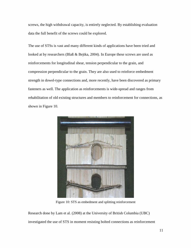
The use of STSs is vast and many different kinds of applications have been tried and
looked at by researchers (Blaß & Bejtka, 2004). In Europe these screws are used as
reinforcements for longitudinal shear, tension perpendicular to the grain, and
compression perpendicular to the grain. They are also used to reinforce embedment
strength in dowel-type connections and, more recently, have been discovered as primary
fasteners as well. The application as reinforcements is wide-spread and ranges from
rehabilitation of old existing structures and members to reinforcement for connections, as
shown in Figure 10.
Figure 10: STS as embedment and splitting reinforcement
Research done by Lam et al. (2008) at the University of British Columbia (UBC)
investigated the use of STS in moment resisting bolted connections as reinforcement

12
perpendicular to the grain. The study compared results of unreinforced specimens to
specimens that were previously broken and rehabilitated using STS as well as specimens
that were reinforced using self-tapping wood screws. The results revealed that the
ultimate capacity as well as ductility of the connections could be improved using STS as
reinforcement. It is worth noting that even the previously broken specimens that were
rehabilitated using STS had significantly higher values of capacity than the unreinforced
specimens. Additional work done by Lam et al. (2010) and Gehloff et al. (2010) at UBC
looked at further increasing the capacity of such moment resisting bolted connections by
using larger diameter bolts with reduced end and edge distances. The results confirmed
that the reinforcement with self-tapping wood screws is a viable method to increase the
capacity and ductility of bolted connections subjected to cyclic loading; even for
connections with larger diameter bolts, which are more prone to splitting, and reduced
end and edge distances.

13
2. EXPERIMENTAL DESIGN / EQUATIONS
2.1. Parameter considerations
The focus of this work is the pull out resistance or withdrawal resistance of self-tapping
screws with continuous thread. Experiments are conducted by testing the pull out
resistance at different angles to the grain in different wood species. The angles of the
screw to the grain are 90 degrees (perpendicular), 45 degrees and 30 degrees. The pull
out resistance will be compared under the afore mentioned angles and different
embedment depths in three different wood species. The chosen wood species are
Douglas-fir and S-P-F glulam, as well as, Hemlock solid sawn timber to cover the most
commonly used construction materials in Canadian heavy timber construction and
density range. The screws used for the tests are Würth ASSY plus VG®, where VG
denotes continuous thread. The Würth ASSY plus VG® screws are of 6 mm, 8 mm and
10 mm in diameter and are provided in various lengths of up to 800 mm for the 10 mm
diameter screws.
Preliminary withdrawal tests were conducted by pulling the screws from the specimens.
Results have shown that the tensile strength of the screw itself became the limiting factor
at embedment depths of ~12d (d = diameter of the screw). The test setup was
re-configured in a way that instead of pulling on the screws, the screws were pushed into
the wood. Preliminary tests also revealed that the heads of the screws failed at the
shoulder between the shaft of the screw and the head when the screws were tested by
pulling them through the specimen. This stress concentration resulted from the grip
device of the test setup which would not be present in real applications. When the screws

14
are used with steel side plates, the screws have to be counter-sunk into the steel plates to
ensure proper contact of the screw head and shoulder with the steel plate to avoid stress
concentrations and premature failure. Further preliminary tests proved that the new
compression based setup was more suitable to get results at higher embedment depths of
up to 16d before the screws failed in buckling. Based on these preliminary results, four
different embedment depths were selected: 4d, 10d, 12d and 16d. The low embedment
depth of 4d was selected to gather insights on the reinforcement of bolted connection
with smaller edge distances.
For each combination of screw diameter, embedment depth, angle to the grain and wood
species, 10 replications were tested. With 108 different setups and 10 replicates for each
setup, a total of 1080 test were conducted and evaluated. Furthermore, the results are
compared to predictions based on the German building code DIN 1052:2004-8 and the
Eurocode 5. Both building codes predict the withdrawal resistance of this type of screws
and therefore their potential as reinforcement in tension perpendicular to grain in dowel-
type connections. Input parameters in the equations in the German code are the mean
specific gravity of the wood, the angle to the grain, the screw diameter and the
embedment depth. These parameters coincide with the studied parameters in the tests
conducted for this study.

15
2.2. Test setup
The machine used for the tests was the Sintech 30/D with a 1,500 kN load cell. Wooden
blocks were used to create enough clearance above the machine test table for the screws.
Steel rectangular tubing was used to reduce the span and therefore limit the deflection of
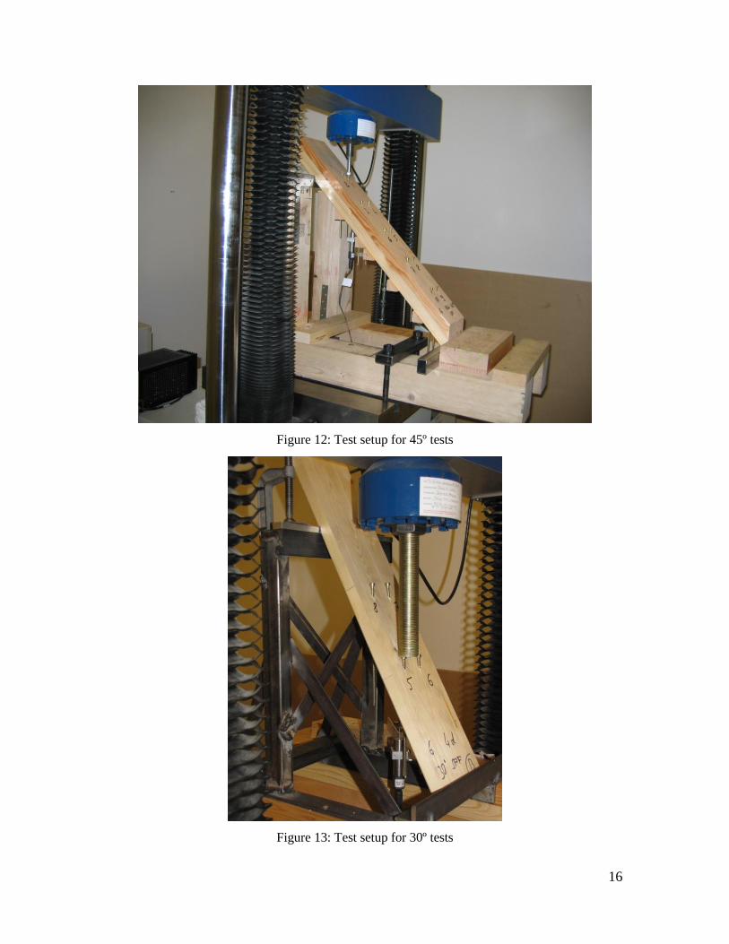
the specimens. A transducer was used to measure the wood deflection near the tested
screw as correction value. Figures 11to13 show the test setup for the 90, 45 and 30 degree
tests respectively. The transducer used to measure the deflection of the specimen is
shown in Figure 14.
Figure 11: Test setup for 90º tests
16
Figure 12: Test setup for 45º tests
Figure 13: Test setup for 30º tests

17
Figure 14: Transducer to measure deflection
As shown in Figures 11 to 13, the screws were driven all the way through the specimen to
eliminate any resistance at the screw tip during testing, as well as to reduce the
slenderness ratio. The reduced slenderness will help prevent buckling of the screws at
higher loads and greater embedment depths. The embedment depth was controlled by the
thickness of the specimens. All specimens were cut and planed to the thickness that
equalled the embedment depth for the specific tests. Table 1 and Figure 15 show the
effective embedment depth for the different screw inclinations. The embedment depths
were chosen to remain constant since, otherwise, not enough material would have been
left to properly install the screws and test the screws without breaking the wood first. In a
situation where the screws are used to reinforce bolted connections the approach would
be similar. The calculated minimum edge distances, even if reduced due to the presence
of self-tapping wood screws as reinforcement for the bolts would, be a value that is

18
perpendicular (90°) to the edges of the beam. Thus, the obtained withdrawal resistance
values are applicable to such reinforcements even if it means that the values for different
screw inclinations cannot be compared directly.
Table 1: Effective embedment depths
Figure 15: Effective embedment depth
Embedment
depth
Effective embedment depth
90° 45° 30°
4d 4d (1/sin 45°) 4d (1/sin 30°) 4d
~ 5.656 d 8 d
10d 10d (1/sin 45°) 10d (1/sin 30°) 10d
~ 14.142 d 20 d
12d 12d (1/sin 45°) 12d (1/sin 30°) 12d
~ 16.968 d 24 d
16d 16d (1/sin 45°) 16d (1/sin 30°) 16d
~ 22.624 d 32 d

19
To transfer the load from the load cell to the head of the self-tapping screw, a harden hex-
head screw was used. Due to the hardness of the self-tapping screw the hex-head was
introduced to avoid damage to the load cell.
Testing was done in accordance with the German standard DIN EN 1832, which specifies
the speed of testing such that failure can be reached in 90 seconds ± 30 seconds. Multiple
screws were placed in the specimens to speed up testing. The row spacing of ≥ 5d as well
as the end, edge and screw spacing of ≥ 10d was followed as given in the standard.
2.3. European code equations
The German wood building code DIN 1052:2004-08 defines the withdrawal resistance of
screws by taking the tensile strength min. fu,k = 400 N/mm2 of the screw, the axial
capacity of the thread in wood and the head-pull through into account. Given that, head
pull through of full threaded screws is neglected, the main parameters influencing
withdrawal resistance are the penetration depth of the thread (lef) including the tip
embedded in the wood, the diameter (d), the angle (α) and the characteristic value of the
withdrawal resistance ( Kf .1 ). Further influencing parameters are the apparent density, as
well as the axial capacity of the threaded part embedded in the wood. Wood screws are
separated into three different strength groups regarding their characteristic axial capacity
parameter ( Kf .1 ). For group one to three, the parameter is 26
,1 10 kKf where the
value ( ) can vary from 60 for group one, 70 for group two and 80 for group three,
respectively. Group one represents any wood screw other than screws that can be placed
into either of the other two groups. Screws with threads in accordance with DIN 7998

20
(Figure 6) can be placed in group two without the need of further proof. Group three, on
the other hand, represents a group for hardened screws that are proven to withstand a
certain threshold capacity and generally require a general construction approval. Self-
tapping wood screws require a general construction approval and fall into group three
unless stated otherwise in the approval of the particular screw. The characteristic value of
the withdrawal resistance kaxR , is calculated by Equation 1.
2
.222
.1
. ;
cos3
4sin
min kK
efK
Kax dfldf
R
[N] (1)
where;
26
,1 10 kKf ,
with ρk = characteristic density, kg/m3
d = outside screw diameter, mm
lef = effective embedment depth including the tip, mm
α = angle between screw length axis and wood grain, degree (°)
The second part of Equation 1 is used to calculate the head pull-through resistance of the
screws, where Kf .2 denotes the characteristic head pull-through parameter and kd the
outside head diameter, or if a washer is used the outside diameter of the washer. In case
of fully threaded self-tapping wood screws, however, the head pull-through resistance is
not considered since the loads are transferred through the thread and the shaft of the
screws and not the head.

21
Equation 1 can only be applied for angles 45°≤ α ≤90°. Blaß and Bejtka (2004) show that
the equation holds true for angles (α) down to 30°. In addition, Blaß et al. (2006) found
that the predicted withdrawal resistance kaxR , is very conservative. Thus, the
characteristic axial capacity Kf .1 could be increased by increasing the value ( ) up to 113
for 90° angles and up to 109 for angles less than 90°.
Contrary to the value of kaxR , presented in DIN 1052:2004-08 where the screw tip is
included in the effective embedment depth of the thread in the wood, Equation (2) of the
Eurocode (EC) 5-2004 considers the screw tip by subtracting one time the diameter (d)
from the embedded length. Furthermore, a possible group effect is taken into
consideration by an exponent for the number of fasteners (n).
22
5.138.09.0
.cos5.1sin
106.3
k
efKax ldnR [N] (2)
where;
d = outside screw diameter, mm
lef = effective embedment depth excluding the tip, mm
ρk = characteristic density, kg/m3
α = angle between screw length axis and wood grain, degree (°)
The findings by Blaß and Bejtka (2003) show Equation 2 over-predicted the withdrawal
resistance kaxR , compared to their test results and, in conclusion, the parameter of 3.6 was
lowered to 2.85 to match the test results.

22
2.4. Equivalency calculations
Neither the Canadian timber building code CSA-O86-09, nor the National Design
Specifications (NDS) in the United States give indication for the calculation of the
withdrawal resistance of wood screws similar to the self-tapping wood screws. As no
technical approvals are in existence to date in North America for this type of screw, only
equivalency calculations can be done. The only dowel type fasteners that are of similar
type and are permitted to be loaded axial in withdrawal are nails and spikes, wood screws
and lag-bolts or lag-screws.
When looking at the Canadian CSA-O86-09, paragraph 10.9.5.1 states that nails and
spikes may only be loaded in withdrawal for wind and earthquake design. The same is
stated for wood screws in paragraph 10.11.5.1. Consequently, an equivalency calculation
is only given for wood screws as they have more similarity to self-tapping wood screws
than nails and spikes. The only fastener permitted to be designed in withdrawal in
accordance with CSA-O86-09 that is similar in shape and function to the self-tapping
wood screw is the lag-bolt or lag-screw. The NDS in the United States, however, permits
the axial loading in withdrawal for all three types of fasteners, the nail and spike, wood
screw as well as the lag-bolt or lag-screw; both terms are used interchangeably.
The withdrawal resistance of lag-bolts in accordance with the Canadian CSA-O86-09 is
calculated with Equation 3 and CSA-O86-09 Table 10.6.5.1 as follows;
eFtwrw JnLYP [N/mm] (3)

23
where;
ɸ = 0.6
Yw = yw (KDKSFKT)
yw = basic withdrawal resistance per millimeter of penetration, N/mm (Table 10.6.5.1)
Lt = length of penetration of threaded portion of lag-bolt in main member, mm
nF = number of lag-bolts in the connection
Je = end grain factor for lag-bolts; 0.75 in end grain, 1.00 in all other cases
For wooden side members an appropriate washer has to be used to prevent the head of the
lag-bolt from pulling through the side member.
The withdrawal resistance of wood-screws in accordance with the Canadian CSA-O86-09
is calculated with Equation 4 and CSA-O86-09 Tables A.10.1 and 10.11.1 as follows;
Ftpwrw nLYP [N/mm] (4)
where;
ɸ = 0.6
Yw = yw (KTKSF)
yw = basic withdrawal resistance per millimeter of threaded shank penetration in main
member; = 68 dF0.82
G1.77
, N/mm
G = mean relative density of main member (Table A.10.1)
df = nominal wood screw diameter, mm (Table 10.11.1)
Lpt = threaded length penetration in the main member, mm
nF = number of wood screws in the connection
For a joint with three members, the threaded length penetration shall be the maximum
24
threaded length within any member other than the head-side member. For wooden side
members an appropriate washer has to be used to prevent the head of the wood screw
from pulling through the side member.
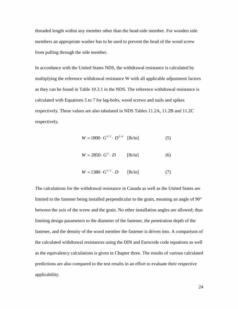
In accordance with the United States NDS, the withdrawal resistance is calculated by
multiplying the reference withdrawal resistance W with all applicable adjustment factors
as they can be found in Table 10.3.1 in the NDS. The reference withdrawal resistance is
calculated with Equations 5 to 7 for lag-bolts, wood screws and nails and spikes
respectively. These values are also tabulated in NDS Tables 11.2A, 11.2B and 11.2C
respectively.
4/32/31800 DGW [lb/in] (5)
DGW 22850 [lb/in] (6)
DGW 2/51380 [lb/in] (7)
The calculations for the withdrawal resistance in Canada as well as the United States are
limited to the fastener being installed perpendicular to the grain, meaning an angle of 90°
between the axis of the screw and the grain. No other installation angles are allowed; thus
limiting design parameters to the diameter of the fastener, the penetration depth of the
fastener, and the density of the wood member the fastener is driven into. A comparison of
the calculated withdrawal resistances using the DIN and Eurocode code equations as well
as the equivalency calculations is given in Chapter three. The results of various calculated
predictions are also compared to the test results in an effort to evaluate their respective
applicability.
25
3. RESULTS / DISCUSSION
3.1. Results
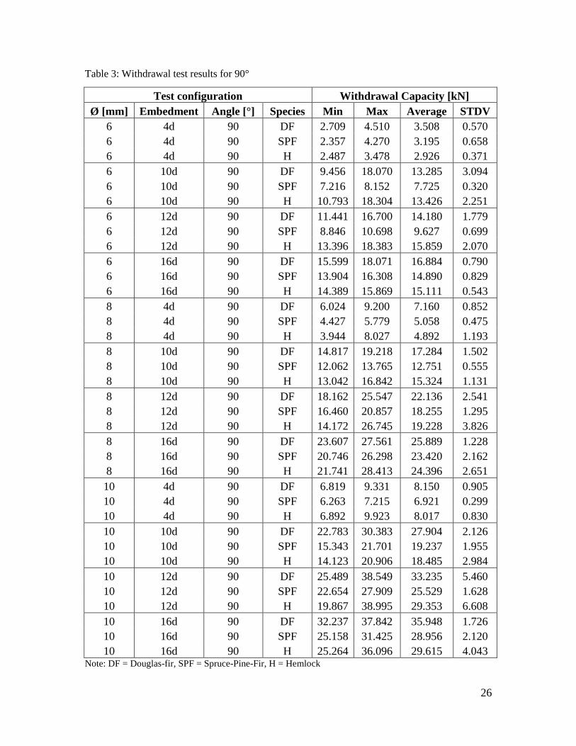
The withdrawal test results are shown in Table 3 through Table 5 for all 108 test series.
Each test configuration was tested with 10 replicates bringing the total number of tests to
1080 individual screws. The tables are formatted to group the results for all screws with
the same angle between the axis of the screw relative to the grain. It should be mentioned
that the results in Tables 3 to 5 showing average values for the 6 mm, 8 mm and 10 mm
screws respectively, are taken from all 10 test replicates and are not calculated based on
the shown minimum and maximum values alone. To display the results a little more
clearly and to be able to understand the effects of different parameters, the results are also
shown in Figures 16 to 24. The figures are divided not only into the angle of screw
installation with respect to the grain, but also split into single screw diameters in order to
keep the graphs legible. The error bars show the minimum and maximum test values.
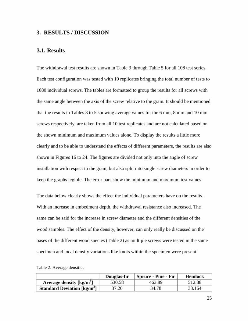
The data below clearly shows the effect the individual parameters have on the results.
With an increase in embedment depth, the withdrawal resistance also increased. The
same can be said for the increase in screw diameter and the different densities of the
wood samples. The effect of the density, however, can only really be discussed on the
bases of the different wood species (Table 2) as multiple screws were tested in the same
specimen and local density variations like knots within the specimen were present.
Table 2: Average densities
Douglas-fir Spruce - Pine - Fir Hemlock
Average density [kg/m3] 530.58 463.89 512.88
Standard Deviation [kg/m3] 37.20 34.78 38.164
26
Table 3: Withdrawal test results for 90°
Test configuration Withdrawal Capacity [kN]
Ø [mm] Embedment Angle [°] Species Min Max Average STDV
6 4d 90 DF 2.709 4.510 3.508 0.570
6 4d 90 SPF 2.357 4.270 3.195 0.658
6 4d 90 H 2.487 3.478 2.926 0.371
6 10d 90 DF 9.456 18.070 13.285 3.094
6 10d 90 SPF 7.216 8.152 7.725 0.320
6 10d 90 H 10.793 18.304 13.426 2.251
6 12d 90 DF 11.441 16.700 14.180 1.779
6 12d 90 SPF 8.846 10.698 9.627 0.699
6 12d 90 H 13.396 18.383 15.859 2.070
6 16d 90 DF 15.599 18.071 16.884 0.790
6 16d 90 SPF 13.904 16.308 14.890 0.829
6 16d 90 H 14.389 15.869 15.111 0.543
8 4d 90 DF 6.024 9.200 7.160 0.852
8 4d 90 SPF 4.427 5.779 5.058 0.475
8 4d 90 H 3.944 8.027 4.892 1.193
8 10d 90 DF 14.817 19.218 17.284 1.502
8 10d 90 SPF 12.062 13.765 12.751 0.555
8 10d 90 H 13.042 16.842 15.324 1.131
8 12d 90 DF 18.162 25.547 22.136 2.541
8 12d 90 SPF 16.460 20.857 18.255 1.295
8 12d 90 H 14.172 26.745 19.228 3.826
8 16d 90 DF 23.607 27.561 25.889 1.228
8 16d 90 SPF 20.746 26.298 23.420 2.162
8 16d 90 H 21.741 28.413 24.396 2.651
10 4d 90 DF 6.819 9.331 8.150 0.905
10 4d 90 SPF 6.263 7.215 6.921 0.299
10 4d 90 H 6.892 9.923 8.017 0.830
10 10d 90 DF 22.783 30.383 27.904 2.126
10 10d 90 SPF 15.343 21.701 19.237 1.955
10 10d 90 H 14.123 20.906 18.485 2.984
10 12d 90 DF 25.489 38.549 33.235 5.460
10 12d 90 SPF 22.654 27.909 25.529 1.628
10 12d 90 H 19.867 38.995 29.353 6.608
10 16d 90 DF 32.237 37.842 35.948 1.726
10 16d 90 SPF 25.158 31.425 28.956 2.120
10 16d 90 H 25.264 36.096 29.615 4.043 Note: DF = Douglas-fir, SPF = Spruce-Pine-Fir, H = Hemlock

27
Figure 16: Average withdrawal resistance for 6 mm screw @ 90º
Figure 17: Average withdrawal resistance for 8 mm screw @ 90º
0.00
2.00
4.00
6.00
8.00
10.00
12.00
14.00
16.00
18.00
20.00
4d 10d 12d 16d
Ava
rege
wit
hd
raw
al
resi
stan
ce [
kN
]
Embedment depth
Würth 6 mm @ 90º angle
Douglas-fir
S-P-F
Hem.-fir
0.00
5.00
10.00
15.00
20.00
25.00
30.00
4d 10d 12d 16d
Avare
ge
wit
hd
raw
al
resi
stan
ce [
kN
]
Embedment depth
Würth 8 mm @ 90º angle
Douglas-fir
S-P-F
Hem.-fir
28
Figure 18: Average withdrawal resistance for 10 mm screw @ 90º
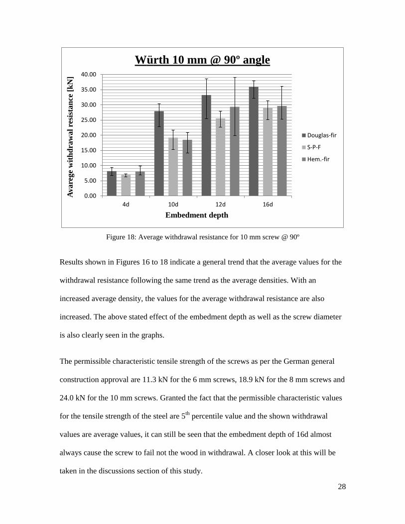
Results shown in Figures 16 to 18 indicate a general trend that the average values for the
withdrawal resistance following the same trend as the average densities. With an
increased average density, the values for the average withdrawal resistance are also
increased. The above stated effect of the embedment depth as well as the screw diameter
is also clearly seen in the graphs.
The permissible characteristic tensile strength of the screws as per the German general
construction approval are 11.3 kN for the 6 mm screws, 18.9 kN for the 8 mm screws and
24.0 kN for the 10 mm screws. Granted the fact that the permissible characteristic values
for the tensile strength of the steel are 5th
percentile value and the shown withdrawal
values are average values, it can still be seen that the embedment depth of 16d almost
always cause the screw to fail not the wood in withdrawal. A closer look at this will be
taken in the discussions section of this study.
0.00
5.00
10.00
15.00
20.00
25.00
30.00
35.00
40.00
4d 10d 12d 16d
Avare
ge
wit
hd
raw
al
resi
stan
ce [
kN
]
Embedment depth
Würth 10 mm @ 90º angle
Douglas-fir
S-P-F
Hem.-fir

29
Table 4: Withdrawal test results for 45°
Test configuration Withdrawal Capacity [kN]
Ø [mm] Embedment Angle [°] Species Min Max Average STDV
6 4d 45 DF 3.978 4.729 4.313 0.243
6 4d 45 SPF 2.370 3.163 2.929 0.223
6 4d 45 H 2.627 6.000 3.278 1.007
6 10d 45 DF 12.447 14.115 13.090 0.553
6 10d 45 SPF 10.559 14.018 11.882 1.131
6 10d 45 H 13.575 15.998 14.419 0.887
6 12d 45 DF 14.111 16.428 15.039 0.654
6 12d 45 SPF 12.492 15.715 13.985 0.915
6 12d 45 H 13.881 15.534 14.701 0.513
6 16d 45 DF 13.347 16.264 15.306 0.831
6 16d 45 SPF 13.915 15.483 14.849 0.487
6 16d 45 H 12.941 16.143 14.635 0.792
8 4d 45 DF 3.494 6.494 5.686 0.947
8 4d 45 SPF 5.727 6.407 6.041 0.218
8 4d 45 H 3.938 7.151 5.177 1.157
8 10d 45 DF 22.388 25.738 23.740 1.071
8 10d 45 SPF 16.722 22.843 19.354 1.859
8 10d 45 H 15.680 23.638 19.864 2.958
8 12d 45 DF 19.805 24.611 22.844 1.549
8 12d 45 SPF 21.311 23.327 22.310 0.559
8 12d 45 H 20.299 23.057 21.760 0.821
8 16d 45 DF 19.942 24.062 21.902 1.130
8 16d 45 SPF 19.811 24.916 21.805 1.474
8 16d 45 H 18.018 23.052 20.833 1.622
10 4d 45 DF 5.795 9.590 7.921 1.260
10 4d 45 SPF 7.012 8.762 7.897 0.624
10 4d 45 H 3.281 12.477 8.563 3.432
10 10d 45 DF 24.315 31.525 29.074 2.107
10 10d 45 SPF 22.840 30.619 27.473 1.988
10 10d 45 H 23.657 30.682 27.798 2.310
10 12d 45 DF 26.833 32.862 30.214 1.730
10 12d 45 SPF 24.673 33.323 29.104 2.463
10 12d 45 H 28.547 33.579 31.241 1.759
10 16d 45 DF 25.259 32.731 29.418 2.124
10 16d 45 SPF 24.369 32.343 28.883 2.180
10 16d 45 H 26.062 32.916 30.086 2.571 Note: DF = Douglas-fir, SPF = Spruce-Pine-Fir, H = Hemlock

30
Figure 19: Average withdrawal resistance for 6 mm screw @ 45º
Figure 20: Average withdrawal resistance for 8 mm screw @ 45º
0.00
2.00
4.00
6.00
8.00
10.00
12.00
14.00
16.00
18.00
20.00
4d 10d 12d 16d
Avare
ge
wit
hd
raw
al
resi
stan
ce [
kN
]
Embedment depth
Würth 6 mm @ 45º angle
Douglas-fir
S-P-F
Hem.-fir
0.00
5.00
10.00
15.00
20.00
25.00
30.00
4d 10d 12d 16d
Avare
ge
wit
hd
raw
al
resi
stan
ce [
kN
]
Embedment depth
Würth 8 mm @ 45º angle
Douglas-fir
S-P-F
Hem.-fir

31
Figure 21: Average withdrawal resistance for 10 mm screw @ 45º
The values for inclination angles of 45°, as well as 30°, are exhibiting similar trends as
seen for the perpendicular to the grain installed screws. However, the effect of the
increased effective embedment depth leads to screw failure in a few cases at a depth of
10d since the effective depth would be about 14d compared to the 90 degree tests (Table
1). This is even more apparent for angles of 30 degrees where almost all specimens at
10d already shown steel failure in the screw instead of withdrawal failure in the wood.
The calculated embedment depth for perpendicular installed screws would be in the range
of 12d to 14d depending on the density of the wood. Figure 25 depicts typical screw
failure as it is reached when the embedment depth exceeds the limit the steel of the screw
can transfer into the wood. Figure 26 shows a typical load displacement plot of the
withdrawal test, all plots can be found in the appendix.
0.00
5.00
10.00
15.00
20.00
25.00
30.00
35.00
40.00
4d 10d 12d 16d
Avare
ge
wit
hd
raw
al
resi
stan
ce [
kN
]
Embedment depth
Würth 10 mm @ 45º angle
Douglas-fir
S-P-F
Hem.-fir

32
Table 5: Withdrawal test results for 30°
Test configuration Withdrawal Capacity [kN]
Ø [mm] Embedment Angle [°] Species Min Max Average STDV
6 4d 30 DF 4.618 7.090 5.893 0.851
6 4d 30 SPF 3.672 6.179 4.430 0.755
6 4d 30 H 4.598 8.079 6.100 1.061
6 10d 30 DF 13.615 15.312 14.511 0.489
6 10d 30 SPF 11.435 14.556 13.087 1.187
6 10d 30 H 13.624 14.519 14.124 0.282
6 12d 30 DF 13.036 15.181 14.179 0.793
6 12d 30 SPF 13.108 14.899 13.978 0.668
6 12d 30 H 12.379 14.568 13.908 0.627
6 16d 30 DF 13.328 14.904 14.059 0.471
6 16d 30 SPF 11.735 14.543 13.517 0.867
6 16d 30 H 13.879 15.175 14.605 0.449
8 4d 30 DF 9.994 16.214 12.789 1.884
8 4d 30 SPF 6.559 13.664 8.522 2.061
8 4d 30 H 8.822 13.466 10.443 2.216
8 10d 30 DF 19.691 23.128 21.451 1.113
8 10d 30 SPF 19.816 24.581 22.273 1.428
8 10d 30 H 19.108 24.780 21.110 1.540
8 12d 30 DF 22.047 26.307 23.875 1.147
8 12d 30 SPF 21.678 24.163 22.679 0.827
8 12d 30 H 19.762 22.221 21.339 1.046
8 16d 30 DF 21.153 23.549 22.201 0.931
8 16d 30 SPF 20.192 22.922 21.526 0.950
8 16d 30 H 17.609 22.266 20.132 1.407
10 4d 30 DF 17.485 20.391 19.083 1.021
10 4d 30 SPF 11.044 17.409 15.224 1.782
10 4d 30 H 12.454 21.633 16.258 3.102
10 10d 30 DF 29.572 34.166 31.217 1.434
10 10d 30 SPF 27.677 31.918 29.731 1.203
10 10d 30 H 25.441 31.039 29.363 1.853
10 12d 30 DF 28.549 31.746 30.727 1.103
10 12d 30 SPF 29.787 33.906 31.389 1.141
10 12d 30 H 26.334 33.890 29.618 2.642
10 16d 30 DF 29.229 35.660 31.540 1.794
10 16d 30 SPF 28.602 32.158 29.936 0.953
10 16d 30 H 19.810 30.257 26.675 3.000 Note: DF = Douglas-fir, SPF = Spruce-Pine-Fir, H = Hemlock

33
Figure 22: Average withdrawal resistance for 6 mm screw @ 30º
Figure 23: Average withdrawal resistance for 8 mm screw @ 30º
0.00
2.00
4.00
6.00
8.00
10.00
12.00
14.00
16.00
18.00
20.00
4d 10d 12d 16d
Avare
ge
wit
hd
raw
al
resi
stan
ce [
kN
]
Embedment depth
Würth 6 mm @ 30º angle
Douglas-fir
S-P-F
Hem.-fir
0.00
5.00
10.00
15.00
20.00
25.00
30.00
4d 10d 12d 16d
Avare
ge
wit
hd
raw
al
resi
stan
ce [
kN
]
Embedment depth
Würth 8 mm @ 30º angle
Douglas-fir
S-P-F
Hem.-fir

34
Figure 24: Average withdrawal resistance for 10 mm screw @ 30º
Figure 25: Typical screw failure
0.00
5.00
10.00
15.00
20.00
25.00
30.00
35.00
40.00
4d 10d 12d 16d
Avare
ge
wit
hd
raw
al
resi
stan
ce [
kN
]
Embedment depth
Würth 10 mm @ 30º angle
Douglas-fir
S-P-F
Hem.-fir

35
Figure 26: Typical load deformation plot
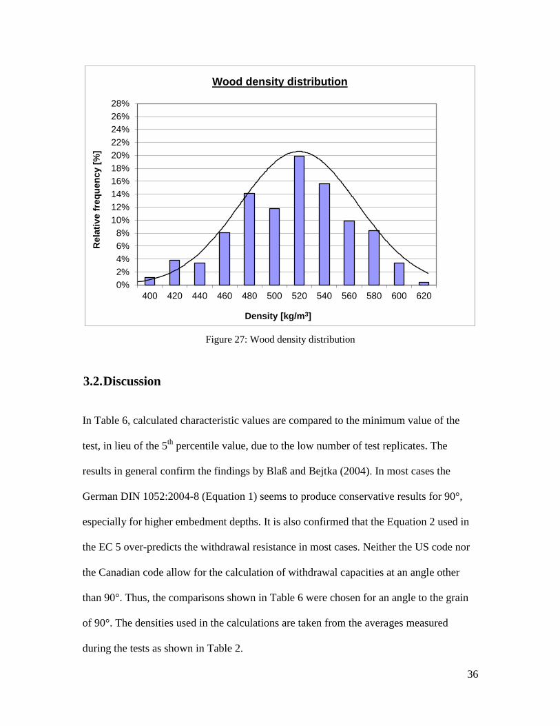
The densities and moisture content for all specimens have been recorded during the
testing. A needle moisture meter was used to measure the moisture content, driving the
needles about 25 mm in to the specimen. The moisture content varied from 7.25% to
13.00% with most specimens having moisture contents between 8.00% and 10.00%. To
establish the density of the specimens, the specimens were weighed at the ambient
climate and their respective moisture contents and measured in all dimensions to establish
their volume. The density was then calculated using the measured weight and volume of
the specimens. Densities for all specimens, regardless of species, have been sorted in
density groups with 20 kg/m3 increments and a normal distribution has then been fitted,
as shown in Figure 27. Figure 27 shows that a normal distribution fits quite well to the
recorded density values.
0
2
4
6
8
10
12
0 0.5 1 1.5 2 2.5 3
Load
[kN
]
Deformation [mm]
Würth 6mm 12d @ 90 deg. - S-P-F
SPEC 1
SPEC 2
SPEC 3
SPEC 4
SPEC 5
SPEC 6
SPEC 7
SPEC 8
SPEC 9
SPEC 10
36
Figure 27: Wood density distribution
3.2. Discussion
In Table 6, calculated characteristic values are compared to the minimum value of the
test, in lieu of the 5th
percentile value, due to the low number of test replicates. The
results in general confirm the findings by Blaß and Bejtka (2004). In most cases the
German DIN 1052:2004-8 (Equation 1) seems to produce conservative results for 90°,
especially for higher embedment depths. It is also confirmed that the Equation 2 used in
the EC 5 over-predicts the withdrawal resistance in most cases. Neither the US code nor
the Canadian code allow for the calculation of withdrawal capacities at an angle other
than 90°. Thus, the comparisons shown in Table 6 were chosen for an angle to the grain
of 90°. The densities used in the calculations are taken from the averages measured
during the tests as shown in Table 2.
0
0.002
0.004
0.006
0.008
0.01
0.012
380 430 480 530 580
0%
2%
4%
6%
8%
10%
12%
14%
16%
18%
20%
22%
24%
26%
28%
400 420 440 460 480 500 520 540 560 580 600 620
Rela
tiv
e f
req
uen
cy [
%]
Density [kg/m3]
Wood density distribution

37
Table 6: Comparison of test results to code equation predictions for STS
Code predictions @ 90° Withdrawal Capacity [kN]
Ø
[mm]
Embed.
Depth
Species
(G)
Min.
Test DIN EC5
CSA
lag
CSA
screw
NDS
lag
NDS
screw
NDS
nail
6
4d 24 DF 0.53 4.51 3.24 5.85 1.78 2.92 1.03 0.84 0.30
4d 24 SPF 0.46 2.36 2.44 4.73 0.74 2.27 0.83 0.63 0.21
4d 24 H 0.51 2.49 3.00 5.52 0.89 2.73 0.97 0.78 0.27
10d 60 DF 0.53 9.46 8.09 12.18 4.44 7.30 2.58 2.10 0.74
10d 60 SPF 0.46 7.22 6.09 9.84 1.86 5.68 2.09 1.58 0.52
10d 60 H 0.51 10.79 7.49 11.49 2.22 6.82 2.44 1.95 0.67
12d 72 DF 0.53 11.44 9.71 14.09 5.33 8.76 3.10 2.52 0.89
12d 72 SPF 0.46 8.85 7.31 11.39 2.23 6.81 2.50 1.90 0.62
12d 72 H 0.51 13.40 8.99 13.30 2.66 8.18 2.92 2.34 0.81
16d 96 DF 0.53 15.60 12.94 17.73 7.10 11.68 4.13 3.36 1.19
16d 96 SPF 0.46 13.90 9.75 14.34 2.98 9.09 3.34 2.53 0.83
16d 96 H 0.51 14.39 11.99 16.74 3.55 10.91 3.90 3.12 1.08
8
4d 32 DF 0.53 6.02 5.75 9.27 3.10 3.89 1.63 1.40 0.49
4d 32 SPF 0.46 4.43 4.33 7.49 1.34 3.03 1.32 1.06 0.35
4d 32 H 0.51 3.94 5.33 8.75 1.76 3.64 1.54 1.30 0.45
10d 80 DF 0.53 14.82 14.38 19.29 7.76 9.73 4.07 3.51 1.24
10d 80 SPF 0.46 12.06 10.83 15.60 3.36 7.57 3.29 2.64 0.87
10d 80 H 0.51 13.04 13.32 18.21 4.40 9.09 3.84 3.25 1.12
12d 96 DF 0.53 18.16 17.26 22.32 9.31 11.68 4.88 4.21 1.48
12d 96 SPF 0.46 16.46 13.00 18.05 4.03 9.09 3.95 3.17 1.04
12d 96 H 0.51 14.17 15.98 21.07 5.28 10.91 4.61 3.89 1.35
16d 128 DF 0.53 23.61 23.01 28.10 12.42 15.57 6.51 5.61 1.98
16d 128 SPF 0.46 20.75 17.33 22.72 5.38 12.12 5.26 4.22 1.39
16d 128 H 0.51 21.74 21.31 26.52 7.04 14.54 6.14 5.19 1.80
10
4d 40 DF 0.53 9.33 8.99 13.25 4.80 4.86 2.33 2.10 0.74
4d 40 SPF 0.46 6.26 6.77 10.71 2.44 3.79 1.89 1.58 0.52
4d 40 H 0.51 6.89 8.32 12.50 2.80 4.54 2.20 1.95 0.67
10d 100 DF 0.53 22.78 22.47 27.57 12.00 12.16 5.83 5.26 1.85
10d 100 SPF 0.46 15.34 16.93 22.29 6.10 9.47 4.71 3.96 1.30
10d 100 H 0.51 14.12 20.81 26.02 7.00 11.36 5.50 4.87 1.68
12d 120 DF 0.53 25.49 26.97 31.90 14.40 14.59 6.99 6.31 2.22
12d 120 SPF 0.46 22.65 20.31 25.79 7.32 11.36 5.66 4.75 1.56
12d 120 H 0.51 19.87 24.97 30.11 8.40 13.63 6.60 5.84 2.02
16d 160 DF 0.53 32.24 35.96 40.15 19.20 19.46 9.33 8.41 2.97
16d 160 SPF 0.46 25.16 27.08 32.47 9.76 15.14 7.54 6.34 2.08
16d 160 H 0.51 25.26 33.29 37.90 11.20 18.18 8.80 7.79 2.69 Note: DF = Douglas-fir, SPF = Spruce-Pine-Fir, H = Hemlock
* ** ** ** ** *** ***
* of 10 tests; ** characteristic value (5th
percentile); *** allowable stress design value
***

38
Using the CSA O86-09 wood screw withdrawal resistance equivalent (Equation 4) gives
the closest values of any of the equivalent methods, but still significantly under-predicts
the test results.
The screw diameter and angle to the grain are considered in Figures 28 to 45, which show
the relationship between DIN and EC5 predicted characteristic withdrawal resistance
compared to test results. The figures show the withdrawal capacities calculated using the
respective code equations of DIN and EC5, which for larger embedment depth is higher
than the tensile strength of the screw itself. The tensile strength of the screws are shown
in the figures as dotted lines, meaning values that are beyond that line would be governed
by the screws tensile strength rather than the withdrawal capacity from the wood. Thus,
the values in the lower left part of the graph are the pivotal ones and considered in the
discussions below.
The results show trends that could generally confirm the work done by Blaß and Bejtka
(2004). The design equation given in the German DIN (Equation 1) are valid for wood of
densities up to 500 kg/m3 and should be carefully checked for applicability to North
American species, especially at higher densities. On the other hand, the EC5 design
equation does not specify a limit in density. When looking at the figures for the
comparison to EC5 (Figures 29 to 45) it shows that the EC5 equation over-predicts the
withdrawal capacities especially when compared to the minimum test values as
mentioned before. The equation according to DIN also over-predicts for the 4d
embedment depths and even more for other depths for screw diameters of 8 mm and 10
mm. For withdrawal values at angles other than 90° the tensile strength of the screw
becomes limiting in most cases due to the increased effective embedment depths.

39
Figure 28: Comparison of 6 mm results with DIN 1052:2004-8 predictions @ 90°
Figure 29: Comparison of 6 mm results with EC 5 predictions @ 90°
0
2
4
6
8
10
12
14
16
18
20
22
24
26
28
30
0 2 4 6 8 10 12 14 16 18 20 22 24 26 28 30Exp
erim
enta
l w
ith
dra
wal
resi
stan
ce [
kN
]
Predicted withdrawal resistance DIN 1052:2004-8 [kN]
Würth 6 mm @ 90º angle
Douglas-fir - 4d
SPF - 4d
Hem.-fir - 4d
Douglas-fir - 10d
SPF - 10d
Hem.-fir - 10d
Douglas-fir - 12d
SPF - 12d
Hem.-fir - 12d
Douglas-fir - 16d
SPF - 16d
Hem.-fir - 16d
tens. capacity
0
2
4
6
8
10
12
14
16
18
20
22
24
26
28
30
0 2 4 6 8 10 12 14 16 18 20 22 24 26 28 30Exp
erim
enta
l w
ith
dra
wal
resi
stan
ce [
kN
]
Predicted withdrawal resistance Eurocode 5 [kN]
Würth 6 mm @ 90º angle Douglas-fir - 4d
SPF - 4d
Hem.-fir - 4d
Douglas-fir - 10d
SPF - 10d
Hem.-fir - 10d
Douglas-fir - 12d
SPF - 12d
Hem.-fir - 12d
Douglas-fir - 16d
SPF - 16d
Hem.-fir - 16d
tens. capacity

40
Figure 30: Comparison of 6 mm results with DIN 1052:2004-8 predictions @ 45°
Figure 31: Comparison of 6 mm results with EC 5 predictions @ 45°
0
2
4
6
8
10
12
14
16
18
20
22
24
26
28
30
0 2 4 6 8 10 12 14 16 18 20 22 24 26 28 30Exp
erim
enta
l w
ith
dra
wal
resi
stan
ce [
kN
]
Predicted withdrawal resistance DIN 1052:2004-8 [kN]
Würth 6 mm @ 45º angle
Douglas-fir - 4d
SPF - 4d
Hem.-fir - 4d
Douglas-fir - 10d
SPF - 10d
Hem.-fir - 10d
Douglas-fir - 12d
SPF - 12d
Hem.-fir - 12d
Douglas-fir - 16d
SPF - 16d
Hem.-fir - 16d
tens. capacity
0
2
4
6
8
10
12
14
16
18
20
22
24
26
28
30
0 2 4 6 8 10 12 14 16 18 20 22 24 26 28 30Exp
erim
enta
l w
ith
dra
wal
resi
stan
ce [
kN
]
Predicted withdrawal resistance Eurocode 5 [kN]
Würth 6 mm @ 45º angle
Douglas-fir - 4d
SPF - 4d
Hem.-fir - 4d
Douglas-fir - 10d
SPF - 10d
Hem.-fir - 10d
Douglas-fir - 12d
SPF - 12d
Hem.-fir - 12d
Douglas-fir - 16d
SPF - 16d
Hem.-fir - 16d
tens. capacity

41
Figure 32: Comparison of 6 mm results with DIN 1052:2004-8 predictions @ 30°
Figure 33: Comparison of 6 mm results with EC 5 predictions @ 30°
0
2
4
6
8
10
12
14
16
18
20
22
24
26
28
30
0 2 4 6 8 10 12 14 16 18 20 22 24 26 28 30Exp
erim
enta
l w
ith
dra
wal
resi
stan
ce [
kN
]
Predicted withdrawal resistance DIN 1052:2004-8 [kN]
Würth 6 mm @ 30º angle
Douglas-fir - 4d
SPF - 4d
Hem.-fir - 4d
Douglas-fir - 10d
SPF - 10d
Hem.-fir - 10d
Douglas-fir - 12d
SPF - 12d
Hem.-fir - 12d
Douglas-fir - 16d
SPF - 16d
Hem.-fir - 16d
tens. capacity
0
2
4
6
8
10
12
14
16
18
20
22
24
26
28
30
0 2 4 6 8 10 12 14 16 18 20 22 24 26 28 30Exp
erim
enta
l w
ith
dra
wal
resi
stan
ce [
kN
]
Predicted withdrawal resistance Eurocode 5 [kN]
Würth 6 mm @ 30º angle
Douglas-fir - 4d
SPF - 4d
Hem.-fir - 4d
Douglas-fir - 10d
SPF - 10d
Hem.-fir - 10d
Douglas-fir - 12d
SPF - 12d
Hem.-fir - 12d
Douglas-fir - 16d
SPF - 16d
Hem.-fir - 16d
tens. capacity

42
Figure 34: Comparison of 8 mm results with DIN 1052:2004-8 predictions @ 90°
Figure 35: Comparison of 8 mm results with EC 5 predictions @ 90°
0
5
10
15
20
25
30
35
40
45
50
55
0 5 10 15 20 25 30 35 40 45 50 55Exp
erim
enta
l w
ith
dra
wal
resi
stan
ce [
kN
]
Predicted withdrawal resistance DIN 1052:2004-8 [kN]
Würth 8 mm @ 90º angle Douglas-fir - 4d
SPF - 4d
Hem.-fir - 4d
Douglas-fir - 10d
SPF - 10d
Hem.-fir - 10d
Douglas-fir - 12d
SPF - 12d
Hem.-fir - 12d
Douglas-fir - 16d
SPF - 16d
Hem.-fir - 16d
tens. capacity
0
5
10
15
20
25
30
35
40
45
50
55
0 5 10 15 20 25 30 35 40 45 50 55Exp
erim
enta
l w
ith
dra
wal
resi
stan
ce [
kN
]
Predicted withdrawal resistance Eurocode 5 [kN]
Würth 8 mm @ 90º angle Douglas-fir - 4d
SPF - 4d
Hem.-fir - 4d
Douglas-fir - 10d
SPF - 10d
Hem.-fir - 10d
Douglas-fir - 12d
SPF - 12d
Hem.-fir - 12d
Douglas-fir - 16d
SPF - 16d
Hem.-fir - 16d
tens. capacity

43
Figure 36: Comparison of 8 mm results with DIN 1052:2004-8 predictions @ 45°
Figure 37: Comparison of 8 mm results with EC 5 predictions @ 45°
0
5
10
15
20
25
30
35
40
45
50
55
0 5 10 15 20 25 30 35 40 45 50 55Exp
erim
enta
l w
ith
dra
wal
resi
stan
ce [
kN
]
Predicted withdrawal resistance DIN 1052:2004-8 [kN]
Würth 8 mm @ 45º angle
Douglas-fir - 4d
SPF - 4d
Hem.-fir - 4d
Douglas-fir - 10d
SPF - 10d
Hem.-fir - 10d
Douglas-fir - 12d
SPF - 12d
Hem.-fir - 12d
Douglas-fir - 16d
SPF - 16d
Hem.-fir - 16d
tens. capacity
0
5
10
15
20
25
30
35
40
45
50
55
0 5 10 15 20 25 30 35 40 45 50 55Exp
erim
enta
l w
ith
dra
wal
resi
stan
ce [
kN
]
Predicted withdrawal resistance Eurocode 5 [kN]
Würth 8 mm @ 45º angle
Douglas-fir - 4d
SPF - 4d
Hem.-fir - 4d
Douglas-fir - 10d
SPF - 10d
Hem.-fir - 10d
Douglas-fir - 12d
SPF - 12d
Hem.-fir - 12d
Douglas-fir - 16d
SPF - 16d
Hem.-fir - 16d
tens. capacity
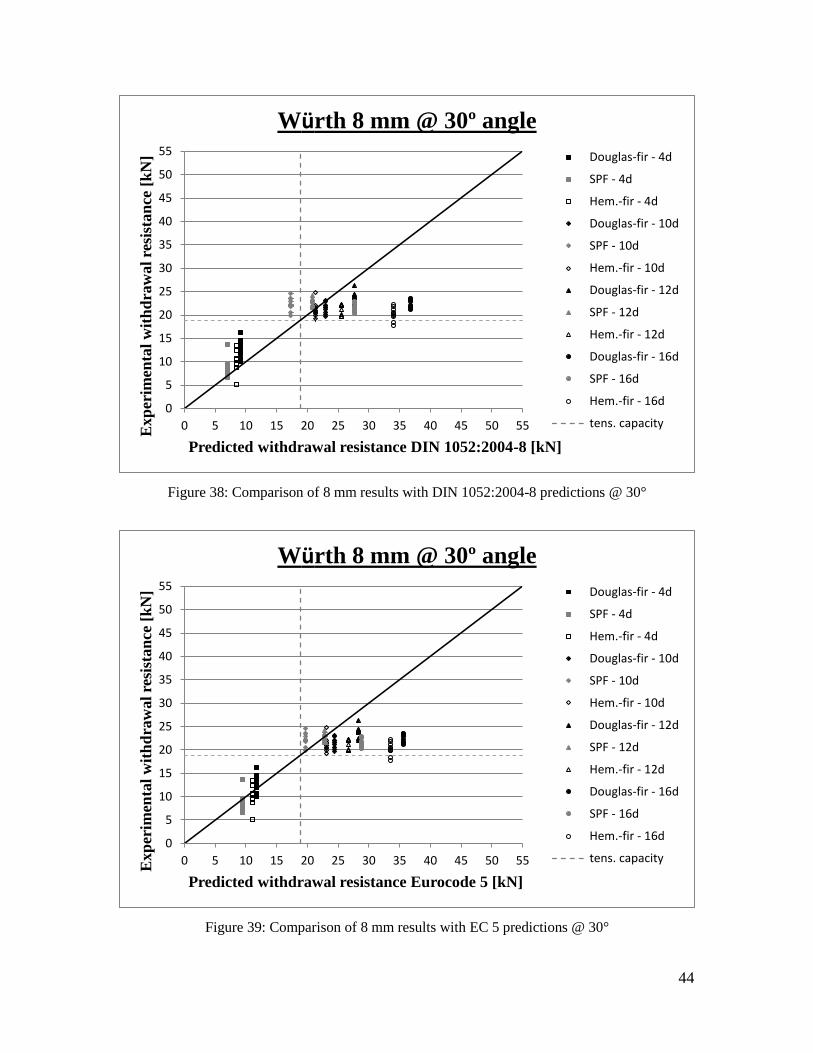
44
Figure 38: Comparison of 8 mm results with DIN 1052:2004-8 predictions @ 30°
Figure 39: Comparison of 8 mm results with EC 5 predictions @ 30°
0
5
10
15
20
25
30
35
40
45
50
55
0 5 10 15 20 25 30 35 40 45 50 55Exp
erim
enta
l w
ith
dra
wal
resi
stan
ce [
kN
]
Predicted withdrawal resistance DIN 1052:2004-8 [kN]
Würth 8 mm @ 30º angle
Douglas-fir - 4d
SPF - 4d
Hem.-fir - 4d
Douglas-fir - 10d
SPF - 10d
Hem.-fir - 10d
Douglas-fir - 12d
SPF - 12d
Hem.-fir - 12d
Douglas-fir - 16d
SPF - 16d
Hem.-fir - 16d
tens. capacity
0
5
10
15
20
25
30
35
40
45
50
55
0 5 10 15 20 25 30 35 40 45 50 55Exp
erim
enta
l w
ith
dra
wal
resi
stan
ce [
kN
]
Predicted withdrawal resistance Eurocode 5 [kN]
Würth 8 mm @ 30º angle
Douglas-fir - 4d
SPF - 4d
Hem.-fir - 4d
Douglas-fir - 10d
SPF - 10d
Hem.-fir - 10d
Douglas-fir - 12d
SPF - 12d
Hem.-fir - 12d
Douglas-fir - 16d
SPF - 16d
Hem.-fir - 16d
tens. capacity

45
Figure 40: Comparison of 10 mm results with DIN 1052:2004-8 predictions @ 90°
Figure 41: Comparison of 10 mm results with EC 5 predictions @ 90°
05
101520253035404550556065707580
0 5 10 15 20 25 30 35 40 45 50 55 60 65 70 75 80Exp
erim
enta
l w
ith
dra
wal
resi
stan
ce [
kN
]
Predicted withdrawal resistance DIN 1052:2004-8 [kN]
Würth 10 mm @ 90º angle Douglas-fir - 4d
SPF - 4d
Hem.-fir - 4d
Douglas-fir - 10d
SPF - 10d
Hem.-fir - 10d
Douglas-fir - 12d
SPF - 12d
Hem.-fir - 12d
Douglas-fir - 16d
SPF - 16d
Hem.-fir - 16d
tens. capacity
05
101520253035404550556065707580
0 5 10 15 20 25 30 35 40 45 50 55 60 65 70 75 80Exp
erim
enta
l w
ith
dra
wal
resi
stan
ce [
kN
]
Predicted withdrawal resistance Eurocode 5 [kN]
Würth 10 mm @ 90º angle Douglas-fir - 4d
SPF - 4d
Hem.-fir - 4d
Douglas-fir - 10d
SPF - 10d
Hem.-fir - 10d
Douglas-fir - 12d
SPF - 12d
Hem.-fir - 12d
Douglas-fir - 16d
SPF - 16d
Hem.-fir - 16d
tens. capacity
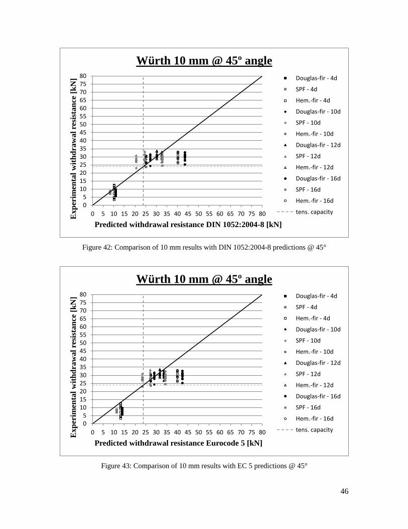
46
Figure 42: Comparison of 10 mm results with DIN 1052:2004-8 predictions @ 45°
Figure 43: Comparison of 10 mm results with EC 5 predictions @ 45°
05
101520253035404550556065707580
0 5 10 15 20 25 30 35 40 45 50 55 60 65 70 75 80Exp
erim
enta
l w
ith
dra
wal
resi
stan
ce [
kN
]
Predicted withdrawal resistance DIN 1052:2004-8 [kN]
Würth 10 mm @ 45º angle
Douglas-fir - 4d
SPF - 4d
Hem.-fir - 4d
Douglas-fir - 10d
SPF - 10d
Hem.-fir - 10d
Douglas-fir - 12d
SPF - 12d
Hem.-fir - 12d
Douglas-fir - 16d
SPF - 16d
Hem.-fir - 16d
tens. capacity
05
101520253035404550556065707580
0 5 10 15 20 25 30 35 40 45 50 55 60 65 70 75 80Exp
erim
enta
l w
ith
dra
wal
resi
stan
ce [
kN
]
Predicted withdrawal resistance Eurocode 5 [kN]
Würth 10 mm @ 45º angle
Douglas-fir - 4d
SPF - 4d
Hem.-fir - 4d
Douglas-fir - 10d
SPF - 10d
Hem.-fir - 10d
Douglas-fir - 12d
SPF - 12d
Hem.-fir - 12d
Douglas-fir - 16d
SPF - 16d
Hem.-fir - 16d
tens. capacity

47
Figure 44: Comparison of 10 mm results with DIN 1052:2004-8 predictions @ 30°
Figure 45: Comparison of 10 mm results with EC 5 predictions @ 30°
05
101520253035404550556065707580
0 5 10 15 20 25 30 35 40 45 50 55 60 65 70 75 80Exp
erim
enta
l w
ith
dra
wal
resi
stan
ce [
kN
]
Predicted withdrawal resistance DIN 1052:2004-8 [kN]
Würth 10 mm @ 30º angle
Douglas-fir - 4d
SPF - 4d
Hem.-fir - 4d
Douglas-fir - 10d
SPF - 10d
Hem.-fir - 10d
Douglas-fir - 12d
SPF - 12d
Hem.-fir - 12d
Douglas-fir - 16d
SPF - 16d
Hem.-fir - 16d
tens. capacity
05
101520253035404550556065707580
0 5 10 15 20 25 30 35 40 45 50 55 60 65 70 75 80Exp
erim
enta
l w
ith
dra
wal
resi
stan
ce [
kN
]
Predicted withdrawal resistance Eurocode 5 [kN]
Würth 10 mm @ 30º angle
Douglas-fir - 4d
SPF - 4d
Hem.-fir - 4d
Douglas-fir - 10d
SPF - 10d
Hem.-fir - 10d
Douglas-fir - 12d
SPF - 12d
Hem.-fir - 12d
Douglas-fir - 16d
SPF - 16d
Hem.-fir - 16d
tens. capacity

48
Results of the study by Blaß et al. (2006) suggested adjustments to Equation 1. Changing
the characteristic axial capacity Kf .1 by increasing the values of to 109 are shown in
Figures 46 to 62. The comparisons of the calculations to the observed test values are un-
conservatively over-predicted and undesirable. The values of should actually be
slightly reduced for major Canadian species, although a larger number of tests than done
in this study are required to make more definitive statements. In case of the by Blaß and
Bejtka (2004) suggested adjustment to Eurocode 5 (Equation 2), the parameter of 3.6 was
lowered to 2.85 to better match the test results and avoid over-predicting the withdrawal
resistance. Figures 47 to 63 show that the adjusted EC5 equation predicts more
conservatively than the unadjusted equation, especially at higher embedment depths. For
embedment depths of 4d the adjusted EC5 equation still over-predicts the withdrawal
capacity, but the results are closer to the observed test results as they were when using the
current, uncorrected EC5 equation. However, neither adjustment properly predicts the
results of the tests and needs to be revisited. For major Canadian species the equations
need to be further optimized, but more test data is required to do so effectively and
accurately.
Another observation is that starting at an embedment depth of about 10d to 12d,
depending on the screw angle, the tensile capacity (as per German General Construction
Approval) of the Würth ASSY plus VG screw is reached.

49
Figure 46: Comparison of 6 mm results with DIN 1052:2004-8 adjustments @ 90°
Figure 47: Comparison of 6 mm results with EC 5 adjustments @ 90°
0
2
4
6
8
10
12
14
16
18
20
22
24
26
28
30
0 2 4 6 8 10 12 14 16 18 20 22 24 26 28 30Exp
erim
enta
l w
ith
dra
wal
resi
stan
ce [
kN
]
Adjusted withdrawal resistance DIN 1052:2004-8 [kN]
Würth 6 mm @ 90º angle Douglas-fir - 4d
SPF - 4d
Hem.-fir - 4d
Douglas-fir - 10d
SPF - 10d
Hem.-fir - 10d
Douglas-fir - 12d
SPF - 12d
Hem.-fir - 12d
Douglas-fir - 16d
SPF - 16d
Hem.-fir - 16d
tens. capacity
0
2
4
6
8
10
12
14
16
18
20
22
24
26
28
30
0 2 4 6 8 10 12 14 16 18 20 22 24 26 28 30Exp
erim
enta
l w
ith
dra
wal
resi
stan
ce [
kN
]
Adjusted withdrawal resistance Eurocode 5 [kN]
Würth 6 mm @ 90º angle Douglas-fir - 4d
SPF - 4d
Hem.-fir - 4d
Douglas-fir - 10d
SPF - 10d
Hem.-fir - 10d
Douglas-fir - 12d
SPF - 12d
Hem.-fir - 12d
Douglas-fir - 16d
SPF - 16d
Hem.-fir - 16d
tens. capacity

50
Figure 48: Comparison of 6 mm results with DIN 1052:2004-8 adjustments @ 45°
Figure 49: Comparison of 6 mm results with EC 5 adjustments @ 45°
0
2
4
6
8
10
12
14
16
18
20
22
24
26
28
30
0 2 4 6 8 10 12 14 16 18 20 22 24 26 28 30Exp
erim
enta
l w
ith
dra
wal
resi
stan
ce [
kN
]
Adjusted withdrawal resistance DIN 1052:2004-8 [kN]
Würth 6 mm @ 45º angle
Douglas-fir - 4d
SPF - 4d
Hem.-fir - 4d
Douglas-fir - 10d
SPF - 10d
Hem.-fir - 10d
Douglas-fir - 12d
SPF - 12d
Hem.-fir - 12d
Douglas-fir - 16d
SPF - 16d
Hem.-fir - 16d
tens. capacity
0
2
4
6
8
10
12
14
16
18
20
22
24
26
28
30
0 2 4 6 8 10 12 14 16 18 20 22 24 26 28 30Exp
erim
enta
l w
ith
dra
wal
resi
stan
ce [
kN
]
Adjusted withdrawal resistance Eurocode 5 [kN]
Würth 6 mm @ 45º angle
Douglas-fir - 4d
SPF - 4d
Hem.-fir - 4d
Douglas-fir - 10d
SPF - 10d
Hem.-fir - 10d
Douglas-fir - 12d
SPF - 12d
Hem.-fir - 12d
Douglas-fir - 16d
SPF - 16d
Hem.-fir - 16d
tens. capacity

51
Figure 50: Comparison of 6 mm results with DIN 1052:2004-8 adjustments @ 30°
Figure 51: Comparison of 6 mm results with EC 5 adjustments @ 30°
0
2
4
6
8
10
12
14
16
18
20
22
24
26
28
30
0 2 4 6 8 10 12 14 16 18 20 22 24 26 28 30Exp
erim
enta
l w
ith
dra
wal
resi
stan
ce [
kN
]
Adjusted withdrawal resistance DIN 1052:2004-8 [kN]
Würth 6 mm @ 30º angle
Douglas-fir - 4d
SPF - 4d
Hem.-fir - 4d
Douglas-fir - 10d
SPF - 10d
Hem.-fir - 10d
Douglas-fir - 12d
SPF - 12d
Hem.-fir - 12d
Douglas-fir - 16d
SPF - 16d
Hem.-fir - 16d
tens. capacity
0
2
4
6
8
10
12
14
16
18
20
22
24
26
28
30
0 2 4 6 8 10 12 14 16 18 20 22 24 26 28 30Exp
erim
enta
l w
ith
dra
wal
resi
stan
ce [
kN
]
Adjusted withdrawal resistance Eurocode 5 [kN]
Würth 6 mm @ 30º angle
Douglas-fir - 4d
SPF - 4d
Hem.-fir - 4d
Douglas-fir - 10d
SPF - 10d
Hem.-fir - 10d
Douglas-fir - 12d
SPF - 12d
Hem.-fir - 12d
Douglas-fir - 16d
SPF - 16d
Hem.-fir - 16d
tens. capacity

52
Figure 52: Comparison of 8 mm results with DIN 1052:2004-8 adjustments @ 90°
Figure 53: Comparison of 8 mm results with EC 5 adjustments @ 90°
0
5
10
15
20
25
30
35
40
45
50
55
0 5 10 15 20 25 30 35 40 45 50 55Exp
erim
enta
l w
ith
dra
wal
resi
stan
ce [
kN
]
Adjusted withdrawal resistance DIN 1052:2004-8 [kN]
Würth 8 mm @ 90º angle Douglas-fir - 4d
SPF - 4d
Hem.-fir - 4d
Douglas-fir - 10d
SPF - 10d
Hem.-fir - 10d
Douglas-fir - 12d
SPF - 12d
Hem.-fir - 12d
Douglas-fir - 16d
SPF - 16d
Hem.-fir - 16d
tens. capacity
0
5
10
15
20
25
30
35
40
45
50
55
0 5 10 15 20 25 30 35 40 45 50 55Exp
erim
enta
l w
ith
dra
wal
resi
stan
ce [
kN
]
Adjusted withdrawal resistance Eurocode 5 [kN]
Würth 8 mm @ 90º angle Douglas-fir - 4d
SPF - 4d
Hem.-fir - 4d
Douglas-fir - 10d
SPF - 10d
Hem.-fir - 10d
Douglas-fir - 12d
SPF - 12d
Hem.-fir - 12d
Douglas-fir - 16d
SPF - 16d
Hem.-fir - 16d
tens. capacity

53
Figure 54: Comparison of 8 mm results with DIN 1052:2004-8 adjustments @ 45°
Figure 55: Comparison of 8 mm results with EC 5 adjustments @ 45°
0
5
10
15
20
25
30
35
40
45
50
55
0 5 10 15 20 25 30 35 40 45 50 55Exp
erim
enta
l w
ith
dra
wal
resi
stan
ce [
kN
]
Adjusted withdrawal resistance DIN 1052:2004-8 [kN]
Würth 8 mm @ 45º angle
Douglas-fir - 4d
SPF - 4d
Hem.-fir - 4d
Douglas-fir - 10d
SPF - 10d
Hem.-fir - 10d
Douglas-fir - 12d
SPF - 12d
Hem.-fir - 12d
Douglas-fir - 16d
SPF - 16d
Hem.-fir - 16d
tens. capacity
0
5
10
15
20
25
30
35
40
45
50
55
0 5 10 15 20 25 30 35 40 45 50 55Exp
erim
enta
l w
ith
dra
wal
resi
stan
ce [
kN
]
Adjusted withdrawal resistance Eurocode 5 [kN]
Würth 8 mm @ 45º angle
Douglas-fir - 4d
SPF - 4d
Hem.-fir - 4d
Douglas-fir - 10d
SPF - 10d
Hem.-fir - 10d
Douglas-fir - 12d
SPF - 12d
Hem.-fir - 12d
Douglas-fir - 16d
SPF - 16d
Hem.-fir - 16d
tens. capacity

54
Figure 56: Comparison of 8 mm results with DIN 1052:2004-8 adjustments @ 30°
Figure 57: Comparison of 8 mm results with EC 5 adjustments @ 30°
0
5
10
15
20
25
30
35
40
45
50
55
0 5 10 15 20 25 30 35 40 45 50 55Exp
erim
enta
l w
ith
dra
wal
resi
stan
ce [
kN
]
Adjusted withdrawal resistance DIN 1052:2004-8 [kN]
Würth 8 mm @ 30º angle
Douglas-fir - 4d
SPF - 4d
Hem.-fir - 4d
Douglas-fir - 10d
SPF - 10d
Hem.-fir - 10d
Douglas-fir - 12d
SPF - 12d
Hem.-fir - 12d
Douglas-fir - 16d
SPF - 16d
Hem.-fir - 16d
tens. capacity
0
5
10
15
20
25
30
35
40
45
50
55
0 5 10 15 20 25 30 35 40 45 50 55Exp
erim
enta
l w
ith
dra
wal
resi
stan
ce [
kN
]
Adjusted withdrawal resistance Eurocode 5 [kN]
Würth 8 mm @ 30º angle
Douglas-fir - 4d
SPF - 4d
Hem.-fir - 4d
Douglas-fir - 10d
SPF - 10d
Hem.-fir - 10d
Douglas-fir - 12d
SPF - 12d
Hem.-fir - 12d
Douglas-fir - 16d
SPF - 16d
Hem.-fir - 16d
tens. capacity
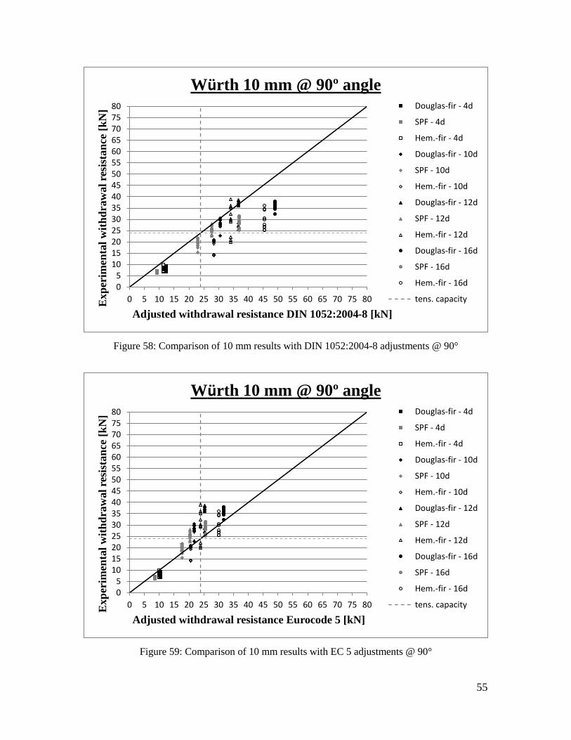
55
Figure 58: Comparison of 10 mm results with DIN 1052:2004-8 adjustments @ 90°
Figure 59: Comparison of 10 mm results with EC 5 adjustments @ 90°
05
101520253035404550556065707580
0 5 10 15 20 25 30 35 40 45 50 55 60 65 70 75 80Exp
erim
enta
l w
ith
dra
wal
resi
stan
ce [
kN
]
Adjusted withdrawal resistance DIN 1052:2004-8 [kN]
Würth 10 mm @ 90º angle Douglas-fir - 4d
SPF - 4d
Hem.-fir - 4d
Douglas-fir - 10d
SPF - 10d
Hem.-fir - 10d
Douglas-fir - 12d
SPF - 12d
Hem.-fir - 12d
Douglas-fir - 16d
SPF - 16d
Hem.-fir - 16d
tens. capacity
05
101520253035404550556065707580
0 5 10 15 20 25 30 35 40 45 50 55 60 65 70 75 80Exp
erim
enta
l w
ith
dra
wal
resi
stan
ce [
kN
]
Adjusted withdrawal resistance Eurocode 5 [kN]
Würth 10 mm @ 90º angle Douglas-fir - 4d
SPF - 4d
Hem.-fir - 4d
Douglas-fir - 10d
SPF - 10d
Hem.-fir - 10d
Douglas-fir - 12d
SPF - 12d
Hem.-fir - 12d
Douglas-fir - 16d
SPF - 16d
Hem.-fir - 16d
tens. capacity

56
Figure 60: Comparison of 10 mm results with DIN 1052:2004-8 adjustments @ 45°
Figure 61: Comparison of 10 mm results with EC 5 adjustments @ 45°
05
101520253035404550556065707580
0 5 10 15 20 25 30 35 40 45 50 55 60 65 70 75 80Exp
erim
enta
l w
ith
dra
wal
resi
stan
ce [
kN
]
Adjusted withdrawal resistance DIN 1052:2004-8 [kN]
Würth 10 mm @ 45º angle
Douglas-fir - 4d
SPF - 4d
Hem.-fir - 4d
Douglas-fir - 10d
SPF - 10d
Hem.-fir - 10d
Douglas-fir - 12d
SPF - 12d
Hem.-fir - 12d
Douglas-fir - 16d
SPF - 16d
Hem.-fir - 16d
tens. capacity
05
101520253035404550556065707580
0 5 10 15 20 25 30 35 40 45 50 55 60 65 70 75 80Exp
erim
enta
l w
ith
dra
wal
resi
stan
ce [
kN
]
Adjusted withdrawal resistance Eurocode 5 [kN]
Würth 10 mm @ 45º angle
Douglas-fir - 4d
SPF - 4d
Hem.-fir - 4d
Douglas-fir - 10d
SPF - 10d
Hem.-fir - 10d
Douglas-fir - 12d
SPF - 12d
Hem.-fir - 12d
Douglas-fir - 16d
SPF - 16d
Hem.-fir - 16d
tens. capacity

57
Figure 62: Comparison of 10 mm results with DIN 1052:2004-8 adjustments @ 30°
Figure 63: Comparison of 10 mm results with EC 5 adjustments @ 45°
05
101520253035404550556065707580
0 5 10 15 20 25 30 35 40 45 50 55 60 65 70 75 80Exp
erim
enta
l w
ith
dra
wal
resi
stan
ce [
kN
]
Adjusted withdrawal resistance DIN 1052:2004-8 [kN]
Würth 10 mm @ 30º angle
Douglas-fir - 4d
SPF - 4d
Hem.-fir - 4d
Douglas-fir - 10d
SPF - 10d
Hem.-fir - 10d
Douglas-fir - 12d
SPF - 12d
Hem.-fir - 12d
Douglas-fir - 16d
SPF - 16d
Hem.-fir - 16d
tens. capacity
05
101520253035404550556065707580
0 5 10 15 20 25 30 35 40 45 50 55 60 65 70 75 80Exp
erim
enta
l w
ith
dra
wal
resi
stan
ce [
kN
]
Adjusted withdrawal resistance Eurocode 5 [kN]
Würth 10 mm @ 30º angle
Douglas-fir - 4d
SPF - 4d
Hem.-fir - 4d
Douglas-fir - 10d
SPF - 10d
Hem.-fir - 10d
Douglas-fir - 12d
SPF - 12d
Hem.-fir - 12d
Douglas-fir - 16d
SPF - 16d
Hem.-fir - 16d
tens. capacity

58
4. CONCLUSIONS AND RECOMMENDATIONS
4.1. Conclusions
Results of this study show that self-tapping wood screws have a high resistance against
pull-out in Canadian Major Species. Combined with their hardened high tensile strength
steel, these STS connectors can be effectively used in reinforcement applications and
direct connections. To utilize the high withdrawal capacity of self-tapping wood screws
most efficiently, they should be installed in such way that the main path of load transfer
is along the length axis of the self-tapping wood screw.
This study has shown that in most cases the equation given in the German DIN predicts
the withdrawal capacity conservatively. However, some cases are under-predicted and
therefore seem unsafe. The EC 5 equation over-predicts the withdrawal capacities of the
screws. The findings clearly show that improvements to the equations need to be done in
order to apply them to major Canadian species. Nevertheless, more data on the
withdrawal resistance of self-tapping wood screws in major Canadian species is required
to develop such improved equations.
When comparing the test results to the equivalency calculations according to CSA O86-
09 and the NDS 2005 (Equations 3 to 7), it becomes apparent that none of the currently
available calculation methods for mechanical fasteners can predict the withdrawal
capacity of self-tapping wood screws. Not only are the predicted values much too
conservative, but the currently available equations also failed to include a parameter for
the angle of the screw axis relative to the angle of the grain. While the European

59
equations are valid for screw inclinations between 90 degree and 30 degrees, the North
American equations are only valid for 90 degree screw angles.
In order to fully utilize the high capacities and therefore advantages of STSs,
modifications to CSA O86-09, as well as NDS 2005 are required. In lieu of changing the
available equations in the North American code, they could be complimented by adopting
an additional section for self-tapping wood screws or fasteners with a thread type similar
to that of STSs. Alternatively, for the immediate future, proprietary construction
approval, or product evaluation reports valid for an individual screw type and
manufacturer could be used to overcome the missing calculation methods in the available
codes.
4.2. Recommendations
The experimental research needs to be continued to 1) increase sample size to allow
proper estimation of characteristic values and 2) complete the parameter study for the
withdrawal resistance of screws from different manufacturers such as the
HECO TOPPIX CC and SPAX to confirm the findings of the study. Furthermore, the
effects of multiple self-tapping screws and respective end and edge distances, as well as
spacing’s of these screws between each other need to be studied. Such studies should
include conditions like changing moisture conditions during the service life of a
connection, as well as during the seasons of the year.
In the Canadian context reliability based design procedures need to be considered to
establish design equations for STS.

60
In order to fully understand the behaviour of connections using self-tapping wood screws,
further studies of the capacities of such screws perpendicular to their length axis as well
as combined forces applied parallel and perpendicular to the axis of the screw are needed.
In most cases combined forces will have to be transmitted and resisted by the self-tapping
wood screws. Such tests have been conducted in Europe by Blaß and Bejtka (2004) to
increase the range of application of STSs.
In addition, more studies should be conducted to build on UBC’s work on using these
screws to reinforce moment resistant connections against perpendicular to the grain and
shear failures. The feasibility of reducing end and edge distances, as well as bolt and row
spacing in moment resisting connections and heavy timber connections in general could
be studied. The reduction of such parameters would allow for more economical use of
timber members in structures and potentially lead to a greater use of wooden members in
mid-rise and commercial structures. In almost all cases, the current minimum distances
are the limiting factor in sizing wooden members in structures of such nature.

61
BIBLIOGRAPHY
ANSI / AF&PA NDS-2005 (2005), NDS: National Design Specifications for Wood
Construction. AF&AP American Wood Council, Washington
Bejtka I., Blaß H.J. (2005) Self-tapping screws as reinforcements in connections with
dowel-type fasteners. International Council for Research and Innovation in Building and
Construction, Working Commission W18 - Timber Structures. Meeting Thirty-Eight,
Karlsruhe, Germany
Blaß H.J., Bejtka I. (2004) Selbstbohrende Holzschrauben und ihre
Anwendungsmöglichkeiten. Holzbaukalender 2004, 3. Jahrgang, Bruderverlag Karlsruhe,
ISBN 3- 87104-136-X, S. 516-541 (2004)
Blaß H.J., Bejtka I., Uibel I. (2006) Tragfähigkeit von Verbindungen mit selbstbohrende
Holzschrauben mit Vollgewinde. Karlsruher Berichte zum Ingenieurholzbau 4,
Universität Karlsruhe, Germany
Blaß H.J., Schmid M., Litze H., Wagner B. (2000) Nail plate reinforced joints with
dowel-type fasteners. World Conference on Timber Engineering 2004. Whistler, British
Columbia, Canada. Proceedings pp. 8.6.4-1 – 8.6.4-8
CEN (Comité Européen de Normalisation) (2004). EN1995-1-1: 2004 (D), Eurocode 5:
Bemessung und Konstruktion von Holzbauten- Teil 1-1: Allgemeines- Allgemeine
Regeln und Regeln für den Hochbau CEN/ TC 250 Structual Eurocodes.
CSA (Canadian Standards Association) Standard (2009). CSA O86-09: Engineering
Design in Wood. Canadian Standards Association, Mississauga
DIBt (Deutsches Institut für Bautechnik) (2006) Allgemeine Bauaufsichtliche Zulassung,
Würth ASSY VG plus Vollgewindeschrauben als Holzverbindungsmittel. DIBt, Berlin
DIN (Deutsches Institut für Normung e.V.) (1975) DIN 7998: Gewinde und
Schraubenenden für Holzschrauben. Beuth Verlag, Berlin

62
DIN (Deutsches Institut für Normung e.V.) (2004) DIN 1052:2004-08: Entwurf,
Berechnung und Bemessung von Holzbauwerken- Allgemeine Bemessungsregeln und
Bemessungsregeln für den Hochbau. Beuth Verlag, Berlin
DIN (Deutsches Institut für Normung e.V.) (2010) DIN 96: Halbrund-Holzschrauben mit
Schlitz. Beuth Verlag, Berlin
DIN (Deutsches Institut für Normung e.V.) (2010) DIN 97: Senk-Holzschrauben mit
Schlitz. Beuth Verlag, Berlin
DIN (Deutsches Institut für Normung e.V.) (2010) DIN 571: Sechkant-Holzschrauben.
Beuth Verlag, Berlin
DIN EN (Deutsches Institut für Normung e.V. ) (1999). DIN EN 1382: Holzbauwerke,
Prüfverfahren - Ausziehtragfähigkeit von Holzverbindungsmitteln. Deutsche Fassung EN
1382. Beuth Verlag, Berlin
Gehloff M., Closen M., Lam F., (2010) Reduced edge distances in bolted timber moment
connections with perpendicular to grain reinforcement. World Conference on Timber
Engineering 2010. Riva del Garda, Italy, CD-ROM Proceedings
Haller P., Birk T., Offermann P., Cebulla H. (2006) Fully fashioned biaxial weft knitted
and stitch bonded textile reinforcements for wood connections. Science Direct,
Composites Part B 37 278-285
Herzog Th. (Hrsg.) (2000) Expodach–roof structure at the world exhibition Hanover
2000. Prestel, Munich, London, New York
Herzog Th., Natterer J., Schweitzer R., Volz M., Winter W. (2003) Holzbauatlas. Edition
DETAIL, Inst. f. internationale Architektur-Dokumentation, Muenchen. Vierte Auflage,
neu bearbeitet
Hockey B. (1999) Truss Plate reinforced bolted connections in Parallel Strand Lumber.
MASc Thesis, University of British Columbia, Department of Wood Sciences,
Vancouver

63
Johansen KW (1949) Theory of Timber Connections. International Association of Bridge
and Structural Engineering, Copenhagen, Publication No. 9, pp. 249-262
Killer J. (1998) Die Bauwerke der Baumeister Grubenmann. Lignum/Baufachverlag, 4.
Auflage
Lam F., Schulte-Wrede M., Yao C.C., Gu J.J., (2008) Moment resistance of bolted timber
connections with perpendicular to grain reinforcements. World Conference on Timber
Engineering 2008. Miyazaki, Japan, CD-ROM Proceedings
Lam F., Gehloff M., Closen M., (2010) Moment-resisting bolted timber connections.
Proceedings of the Institute of Civil Engineers, Volume 163 Issue SB4. London, UK,
ISSN 0965-0911, pp. 267-274
Madsen B. (2000) Behaviour of Timber Connections. First Edition, Timber Engineering
Ltd., North Vancouver, ISBN 1-55056-738-1
Müller Ch. (2000) Holzleimbau Laminated Timber Construction. Birkhäuser, Basel;
Berlin; Boston, ISBN 0-7643-6267-7 (2000)
Zimmer P. (2002) Die Konstruktionsgeschichte Hölzerner Brücken zwischen 1750 und
1850. Interner Forschungsbericht, Fakultät Architektur der TU Dresden

64
APPENDIX – SUPPLEMENTAL MATERIAL
Figure 64: Load – Deformation (6mm, 4d, 90°, Douglas-fir)
Figure 65: Load – Deformation (6mm, 4d, 90°, S-P-F)
0
0.5
1
1.5
2
2.5
3
3.5
4
4.5
5
0 0.5 1 1.5 2 2.5 3
Load
[kN
]
Deformation [mm]
Würth 6mm 4d @ 90 deg. - Douglas-fir
SPEC 1
SPEC 2
SPEC 3
SPEC 4
SPEC 5
SPEC 6
SPEC 7
SPEC 8
SPEC 9
SPEC 10
0
0.5
1
1.5
2
2.5
3
3.5
4
4.5
5
0 0.5 1 1.5 2 2.5 3
Load
[kN
]
Deformation [mm]
Würth 6mm 4d @ 90 deg. - S-P-F
SPEC 1
SPEC 2
SPEC 3
SPEC 4
SPEC 5
SPEC 6
SPEC 7
SPEC 8
SPEC 9
SPEC 10

65
Figure 66: Load – Deformation (6mm, 4d, 90°, Hemlock)
Figure 67: Load – Deformation (6mm, 4d, 45°, Douglas-fir)
0
0.5
1
1.5
2
2.5
3
3.5
4
4.5
5
0 0.5 1 1.5 2 2.5 3
Load
[kN
]
Deformation [mm]
Würth 6mm 4d @ 90 deg. - Hemlock
SPEC 1
SPEC 2
SPEC 3
SPEC 4
SPEC 5
SPEC 6
SPEC 7
SPEC 8
SPEC 9
SPEC 10
0
1
2
3
4
5
6
0 0.5 1 1.5 2 2.5 3 3.5
Load
[kN
]
Deformation [mm]
Würth 6mm 4d @ 45 deg. - Douglas-fir
SPEC 1
SPEC 2
SPEC 3
SPEC 4
SPEC 5
SPEC 6
SPEC 7
SPEC 8
SPEC 9
SPEC 10

66
Figure 68: Load – Deformation (6mm, 4d, 45°, S-P-F)
Figure 69: Load – Deformation (6mm, 4d, 45°, Hemlock)
0
1
2
3
4
5
6
0 0.5 1 1.5 2 2.5 3 3.5
Load
[kN
]
Deformation [mm]
Würth 6mm 4d @ 45 deg. - S-P-F
SPEC 1
SPEC 2
SPEC 3
SPEC 4
SPEC 5
SPEC 6
SPEC 7
SPEC 8
SPEC 9
SPEC 10
0
1
2
3
4
5
6
0 0.5 1 1.5 2 2.5 3 3.5
Load
[kN
]
Deformation [mm]
Würth 6mm 4d @ 45 deg. - Hemlock
SPEC 1
SPEC 2
SPEC 3
SPEC 4
SPEC 5
SPEC 6
SPEC 7
SPEC 8
SPEC 9
SPEC 10
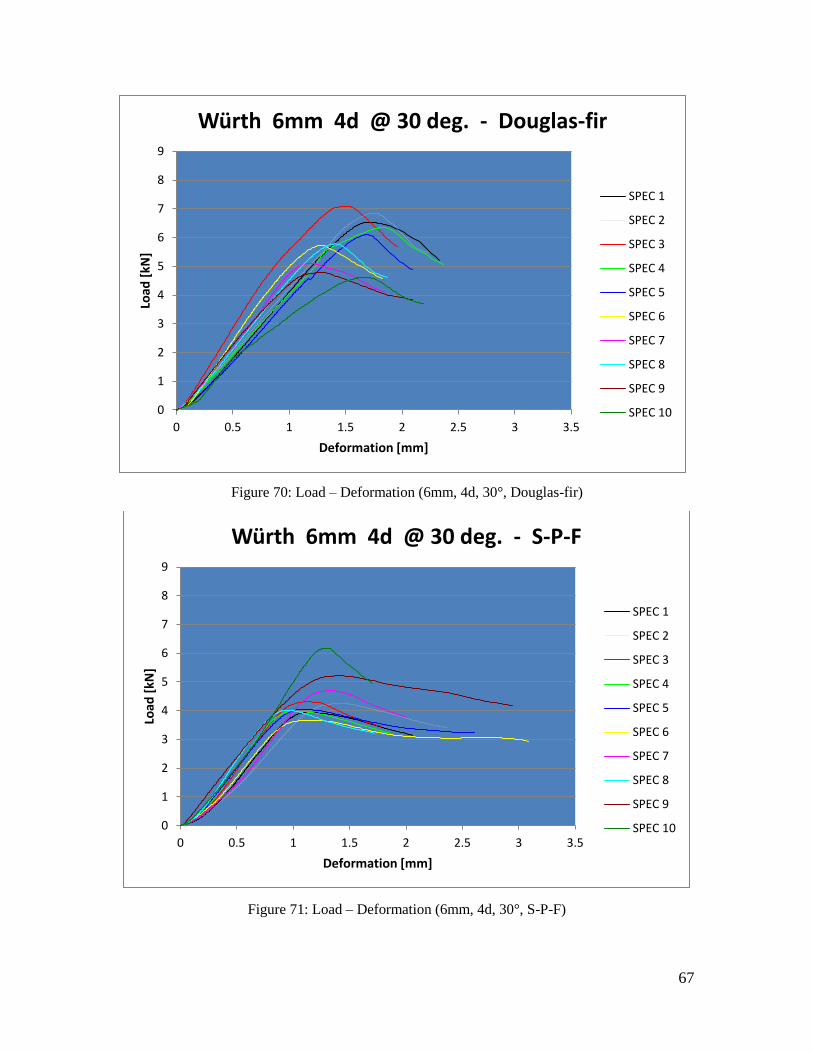
67
Figure 70: Load – Deformation (6mm, 4d, 30°, Douglas-fir)
Figure 71: Load – Deformation (6mm, 4d, 30°, S-P-F)
0
1
2
3
4
5
6
7
8
9
0 0.5 1 1.5 2 2.5 3 3.5
Load
[kN
]
Deformation [mm]
Würth 6mm 4d @ 30 deg. - Douglas-fir
SPEC 1
SPEC 2
SPEC 3
SPEC 4
SPEC 5
SPEC 6
SPEC 7
SPEC 8
SPEC 9
SPEC 10
0
1
2
3
4
5
6
7
8
9
0 0.5 1 1.5 2 2.5 3 3.5
Load
[kN
]
Deformation [mm]
Würth 6mm 4d @ 30 deg. - S-P-F
SPEC 1
SPEC 2
SPEC 3
SPEC 4
SPEC 5
SPEC 6
SPEC 7
SPEC 8
SPEC 9
SPEC 10

68
Figure 72: Load – Deformation (6mm, 4d, 30°, Hemlock)
Figure 73: Load – Deformation (6mm, 10d, 90°, Douglas-fir)
0
1
2
3
4
5
6
7
8
9
0 0.5 1 1.5 2 2.5 3 3.5
Load
[kN
]
Deformation [mm]
Würth 6mm 4d @ 30 deg. - Hemlock
SPEC 1
SPEC 2
SPEC 3
SPEC 4
SPEC 5
SPEC 6
SPEC 7
SPEC 8
SPEC 9
SPEC 10
0
2
4
6
8
10
12
14
16
18
20
0 0.5 1 1.5 2 2.5 3 3.5 4
Load
[kN
]
Deformation [mm]
Würth 6mm 10d @ 90 deg. - Douglas-fir
SPEC 1
SPEC 2
SPEC 3
SPEC 4
SPEC 5
SPEC 6
SPEC 7
SPEC 8
SPEC 9
SPEC 10

69
Figure 74: Load – Deformation (6mm, 10d, 90°, S-P-F)
Figure 75: Load – Deformation (6mm, 10d, 90°, Hemlock)
0
2
4
6
8
10
12
14
16
18
20
0 0.5 1 1.5 2 2.5 3 3.5 4
Load
[kN
]
Deformation [mm]
Würth 6mm 10d @ 90 deg. - S-P-F
SPEC 1
SPEC 2
SPEC 3
SPEC 4
SPEC 5
SPEC 6
SPEC 7
SPEC 8
SPEC 9
SPEC 10
0
2
4
6
8
10
12
14
16
18
20
0 0.5 1 1.5 2 2.5 3 3.5 4
Load
[kN
]
Deformation [mm]
Würth 6mm 10d @ 90 deg. - Hemlock
SPEC 1
SPEC 2
SPEC 3
SPEC 4
SPEC 5
SPEC 6
SPEC 7
SPEC 8
SPEC 9
SPEC 10

70
Figure 76: Load – Deformation (6mm, 10d, 45°, Douglas-fir)
Figure 77: Load – Deformation (6mm, 10d, 45°, S-P-F)
0
2
4
6
8
10
12
14
16
18
0 0.5 1 1.5 2 2.5 3
Load
[kN
]
Deformation [mm]
Würth 6mm 10d @ 45 deg. - Douglas-fir
SPEC 1
SPEC 2
SPEC 3
SPEC 4
SPEC 5
SPEC 6
SPEC 7
SPEC 8
SPEC 9
SPEC 10
0
2
4
6
8
10
12
14
16
18
0 0.5 1 1.5 2 2.5 3
Load
[kN
]
Deformation [mm]
Würth 6mm 10d @ 45 deg. - S-P-F
SPEC 1
SPEC 2
SPEC 3
SPEC 4
SPEC 5
SPEC 6
SPEC 7
SPEC 8
SPEC 9
SPEC 10

71
Figure 78: Load – Deformation (6mm, 10d, 45°, Hemlock)
Figure 79: Load – Deformation (6mm, 10d, 30°, Douglas-fir)
0
2
4
6
8
10
12
14
16
18
0 0.5 1 1.5 2 2.5 3
Load
[kN
]
Deformation [mm]
Würth 6mm 10d @ 45 deg. - Hemlock
SPEC 1
SPEC 2
SPEC 3
SPEC 4
SPEC 5
SPEC 6
SPEC 7
SPEC 8
SPEC 9
SPEC 10
0
2
4
6
8
10
12
14
16
0 0.5 1 1.5 2 2.5 3 3.5
Load
[kN
]
Deformation [mm]
Würth 6mm 10d @ 30 deg. - Douglas-fir
SPEC 1
SPEC 2
SPEC 3
SPEC 4
SPEC 5
SPEC 6
SPEC 7
SPEC 8
SPEC 9
SPEC 10

72
Figure 80: Load – Deformation (6mm, 10d, 30°, S-P-F)
Figure 81: Load – Deformation (6mm, 10d, 30°, Hemlock)
0
2
4
6
8
10
12
14
16
0 0.5 1 1.5 2 2.5 3 3.5
Load
[kN
]
Deformation [mm]
Würth 6mm 10d @ 30 deg. - S-P-F
SPEC 1
SPEC 2
SPEC 3
SPEC 4
SPEC 5
SPEC 6
SPEC 7
SPEC 8
SPEC 9
SPEC 10
0
2
4
6
8
10
12
14
16
0 0.5 1 1.5 2 2.5 3 3.5
Load
[kN
]
Deformation [mm]
Würth 6mm 10d @ 30 deg. - Hemlock
SPEC 1
SPEC 2
SPEC 3
SPEC 4
SPEC 5
SPEC 6
SPEC 7
SPEC 8
SPEC 9
SPEC 10

73
Figure 82: Load – Deformation (6mm, 12d, 90°, Douglas-fir)
Figure 83: Load – Deformation (6mm, 12d, 90°, S-P-F)
0
2
4
6
8
10
12
14
16
18
20
0 0.5 1 1.5 2 2.5 3 3.5 4
Load
[kN
]
Deformation [mm]
Würth 6mm 12d @ 90 deg. - Douglas-fir
SPEC 1
SPEC 2
SPEC 3
SPEC 4
SPEC 5
SPEC 6
SPEC 7
SPEC 8
SPEC 9
SPEC 10
0
2
4
6
8
10
12
14
16
18
20
0 0.5 1 1.5 2 2.5 3 3.5 4
Load
[kN
]
Deformation [mm]
Würth 6mm 12d @ 90 deg. - S-P-F
SPEC 1
SPEC 2
SPEC 3
SPEC 4
SPEC 5
SPEC 6
SPEC 7
SPEC 8
SPEC 9
SPEC 10

74
Figure 84: Load – Deformation (6mm, 12d, 90°, Hemlock)
Figure 85: Load – Deformation (6mm, 12d, 45°, Douglas-fir)
0
2
4
6
8
10
12
14
16
18
20
0 0.5 1 1.5 2 2.5 3 3.5 4
Load
[kN
]
Deformation [mm]
Würth 6mm 12d @ 90 deg. - Hemlock
SPEC 1
SPEC 2
SPEC 3
SPEC 4
SPEC 5
SPEC 6
SPEC 7
SPEC 8
SPEC 9
SPEC 10
0
2
4
6
8
10
12
14
16
18
0 0.5 1 1.5 2 2.5 3
Load
[kN
]
Deformation [mm]
Würth 6mm 12d @ 45 deg. - Douglas-fir
SPEC 1
SPEC 2
SPEC 3
SPEC 4
SPEC 5
SPEC 6
SPEC 7
SPEC 8
SPEC 9
SPEC 10

75
Figure 86: Load – Deformation (6mm, 12d, 45°, S-P-F)
Figure 87: Load – Deformation (6mm, 12d, 45°, Hemlock)
0
2
4
6
8
10
12
14
16
18
0 0.5 1 1.5 2 2.5 3
Load
[kN
]
Deformation [mm]
Würth 6mm 12d @ 45 deg. - S-P-F
SPEC 1
SPEC 2
SPEC 3
SPEC 4
SPEC 5
SPEC 6
SPEC 7
SPEC 8
SPEC 9
SPEC 10
0
2
4
6
8
10
12
14
16
18
0 0.5 1 1.5 2 2.5 3
Load
[kN
]
Deformation [mm]
Würth 6mm 12d @ 45 deg. - Hemlock
SPEC 1
SPEC 2
SPEC 3
SPEC 4
SPEC 5
SPEC 6
SPEC 7
SPEC 8
SPEC 9
SPEC 10
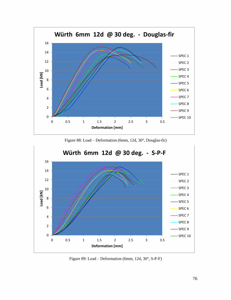
76
Figure 88: Load – Deformation (6mm, 12d, 30°, Douglas-fir)
Figure 89: Load – Deformation (6mm, 12d, 30°, S-P-F)
0
2
4
6
8
10
12
14
16
0 0.5 1 1.5 2 2.5 3 3.5
Load
[kN
]
Deformation [mm]
Würth 6mm 12d @ 30 deg. - Douglas-fir
SPEC 1
SPEC 2
SPEC 3
SPEC 4
SPEC 5
SPEC 6
SPEC 7
SPEC 8
SPEC 9
SPEC 10
0
2
4
6
8
10
12
14
16
0 0.5 1 1.5 2 2.5 3 3.5
Load
[kN
]
Deformation [mm]
Würth 6mm 12d @ 30 deg. - S-P-F
SPEC 1
SPEC 2
SPEC 3
SPEC 4
SPEC 5
SPEC 6
SPEC 7
SPEC 8
SPEC 9
SPEC 10

77
Figure 90: Load – Deformation (6mm, 12d, 30°, Hemlock)
Figure 91: Load – Deformation (6mm, 16d, 90°, Douglas-fir)
0
2
4
6
8
10
12
14
16
0 0.5 1 1.5 2 2.5 3 3.5
Load
[kN
]
Deformation [mm]
Würth 6mm 12d @ 30 deg. - Hemlock
SPEC 1
SPEC 2
SPEC 3
SPEC 4
SPEC 5
SPEC 6
SPEC 7
SPEC 8
SPEC 9
SPEC 10
0
2
4
6
8
10
12
14
16
18
20
0 0.5 1 1.5 2 2.5 3 3.5 4
Load
[kN
]
Deformation [mm]
Würth 6mm 16d @ 90 deg. - Douglas-fir
SPEC 1
SPEC 2
SPEC 3
SPEC 4
SPEC 5
SPEC 6
SPEC 7
SPEC 8
SPEC 9
SPEC 10

78
Figure 92: Load – Deformation (6mm, 16d, 90°, S-P-F)
Figure 93: Load – Deformation (6mm, 16d, 90°, Hemlock)
0
2
4
6
8
10
12
14
16
18
20
0 0.5 1 1.5 2 2.5 3 3.5 4
Load
[kN
]
Deformation [mm]
Würth 6mm 16d @ 90 deg. - S-P-F
SPEC 1
SPEC 2
SPEC 3
SPEC 4
SPEC 5
SPEC 6
SPEC 7
SPEC 8
SPEC 9
SPEC 10
0
2
4
6
8
10
12
14
16
18
20
0 0.5 1 1.5 2 2.5 3 3.5 4
Load
[kN
]
Deformation [mm]
Würth 6mm 16d @ 90 deg. - Hemlock
SPEC 1
SPEC 2
SPEC 3
SPEC 4
SPEC 5
SPEC 6
SPEC 7
SPEC 8
SPEC 9
SPEC 10

79
Figure 94: Load – Deformation (6mm, 16d, 45°, Douglas-fir)
Figure 95: Load – Deformation (6mm, 16d, 45°, S-P-F)
0
2
4
6
8
10
12
14
16
18
0 0.5 1 1.5 2 2.5 3
Load
[kN
]
Deformation [mm]
Würth 6mm 16d @ 45 deg. - Douglas-fir
SPEC 1
SPEC 2
SPEC 3
SPEC 4
SPEC 5
SPEC 6
SPEC 7
SPEC 8
SPEC 9
SPEC 10
0
2
4
6
8
10
12
14
16
18
0 0.5 1 1.5 2 2.5 3
Load
[kN
]
Deformation [mm]
Würth 6mm 16d @ 45 deg. - S-P-F
SPEC 1
SPEC 2
SPEC 3
SPEC 4
SPEC 5
SPEC 6
SPEC 7
SPEC 8
SPEC 9
SPEC 10

80
Figure 96: Load – Deformation (6mm, 16d, 45°, Hemlock)
Figure 97: Load – Deformation (6mm, 16d, 30°, Douglas-fir)
0
2
4
6
8
10
12
14
16
18
0 0.5 1 1.5 2 2.5 3
Load
[kN
]
Deformation [mm]
Würth 6mm 16d @ 45 deg. - Hemlock
SPEC 1
SPEC 2
SPEC 3
SPEC 4
SPEC 5
SPEC 6
SPEC 7
SPEC 8
SPEC 9
SPEC 10
0
2
4
6
8
10
12
14
16
0 0.5 1 1.5 2 2.5 3 3.5
Load
[kN
]
Deformation [mm]
Würth 6mm 16d @ 30 deg. - Douglas-fir
SPEC 1
SPEC 2
SPEC 3
SPEC 4
SPEC 5
SPEC 6
SPEC 7
SPEC 8
SPEC 9
SPEC 10
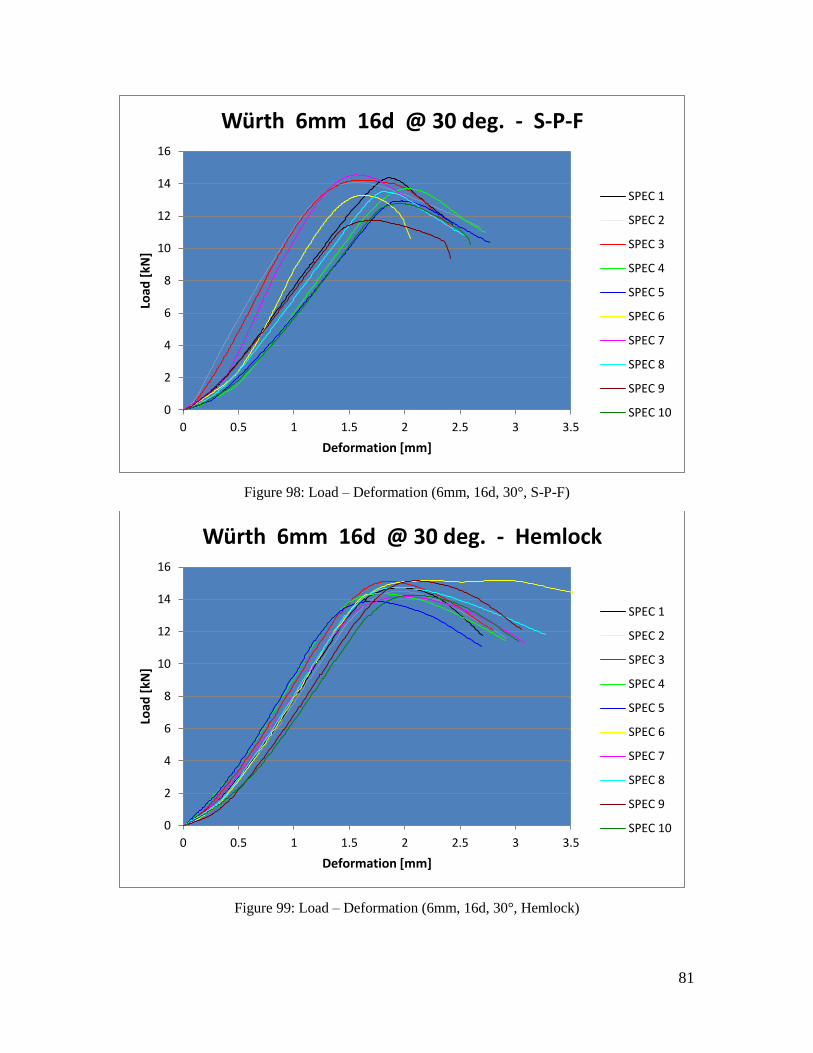
81
Figure 98: Load – Deformation (6mm, 16d, 30°, S-P-F)
Figure 99: Load – Deformation (6mm, 16d, 30°, Hemlock)
0
2
4
6
8
10
12
14
16
0 0.5 1 1.5 2 2.5 3 3.5
Load
[kN
]
Deformation [mm]
Würth 6mm 16d @ 30 deg. - S-P-F
SPEC 1
SPEC 2
SPEC 3
SPEC 4
SPEC 5
SPEC 6
SPEC 7
SPEC 8
SPEC 9
SPEC 10
0
2
4
6
8
10
12
14
16
0 0.5 1 1.5 2 2.5 3 3.5
Load
[kN
]
Deformation [mm]
Würth 6mm 16d @ 30 deg. - Hemlock
SPEC 1
SPEC 2
SPEC 3
SPEC 4
SPEC 5
SPEC 6
SPEC 7
SPEC 8
SPEC 9
SPEC 10

82
Figure 100: Load – Deformation (8mm, 4d, 90°, Douglas-fir)
Figure 101: Load – Deformation (8mm, 4d, 90°, S-P-F)
0
1
2
3
4
5
6
7
8
9
10
0 0.5 1 1.5 2 2.5 3 3.5 4 4.5
Load
[kN
]
Deformation [mm]
Würth 8mm 4d @ 90 deg. - Douglas-fir
SPEC 1
SPEC 2
SPEC 3
SPEC 4
SPEC 5
SPEC 6
SPEC 7
SPEC 8
SPEC 9
SPEC 10
SPEC 11
0
1
2
3
4
5
6
7
8
9
10
0 0.5 1 1.5 2 2.5 3 3.5 4 4.5
Load
[kN
]
Deformation [mm]
Würth 8mm 4d @ 90 deg. - S-P-F
SPEC 1
SPEC 2
SPEC 3
SPEC 4
SPEC 5
SPEC 6
SPEC 7
SPEC 8
SPEC 9
SPEC 10

83
Figure 102: Load – Deformation (8mm, 4d, 90°, Hemlock)
Figure 103: Load – Deformation (8mm, 4d, 45°, Douglas-fir)
0
1
2
3
4
5
6
7
8
9
10
0 0.5 1 1.5 2 2.5 3 3.5 4 4.5
Load
[kN
]
Deformation [mm]
Würth 8mm 4d @ 90 deg. - Hemlock
SPEC 1
SPEC 2
SPEC 3
SPEC 4
SPEC 5
SPEC 6
SPEC 7
SPEC 8
SPEC 9
SPEC 10
0
1
2
3
4
5
6
7
8
0 1 2 3 4 5 6
Load
[kN
]
Deformation [mm]
Würth 8mm 4d @ 45 deg. - Douglas-fir
SPEC 1
SPEC 2
SPEC 3
SPEC 4
SPEC 5
SPEC 6
SPEC 7
SPEC 8
SPEC 9
SPEC 10

84
Figure 104: Load – Deformation (8mm, 4d, 45°, S-P-F)
Figure 105: Load – Deformation (8mm, 4d, 45°, Hemlock)
0
1
2
3
4
5
6
7
8
0 1 2 3 4 5 6
Load
[kN
]
Deformation [mm]
Würth 8mm 4d @ 45 deg. - S-P-F
SPEC 1
SPEC 2
SPEC 3
SPEC 4
SPEC 5
SPEC 6
SPEC 7
SPEC 8
SPEC 9
SPEC 10
0
1
2
3
4
5
6
7
8
0 1 2 3 4 5 6
Load
[kN
]
Deformation [mm]
Würth 8mm 4d @ 45 deg. - Hemlock
SPEC 1
SPEC 2
SPEC 3
SPEC 4
SPEC 5
SPEC 6
SPEC 7
SPEC 8
SPEC 9

85
Figure 106: Load – Deformation (8mm, 4d, 30°, Douglas-fir)
Figure 107: Load – Deformation (8mm, 4d, 30°, S-P-F)
0
2
4
6
8
10
12
14
16
18
0 0.5 1 1.5 2 2.5 3 3.5 4
Load
[kN
]
Deformation [mm]
Würth 8mm 4d @ 30 deg. - Douglas-fir
SPEC 1
SPEC 2
SPEC 3
SPEC 4
SPEC 5
SPEC 6
SPEC 7
SPEC 8
SPEC 9
SPEC 10
0
2
4
6
8
10
12
14
16
18
0 0.5 1 1.5 2 2.5 3 3.5 4
Load
[kN
]
Deformation [mm]
Würth 8mm 4d @ 30 deg. - S-P-F
SPEC 1
SPEC 2
SPEC 3
SPEC 4
SPEC 5
SPEC 6
SPEC 7
SPEC 8
SPEC 9
SPEC 10
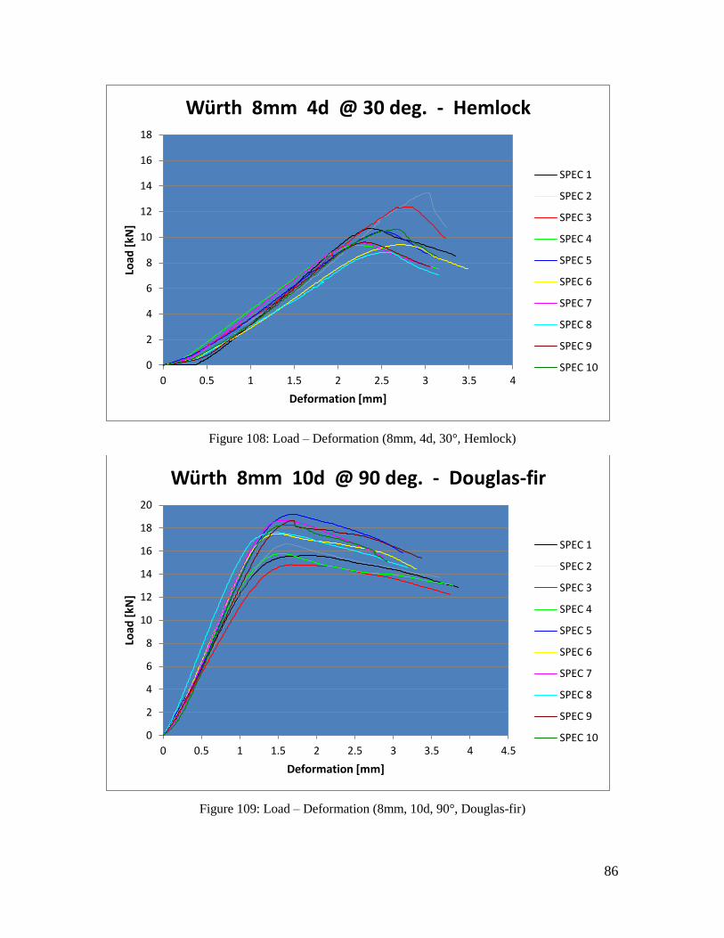
86
Figure 108: Load – Deformation (8mm, 4d, 30°, Hemlock)
Figure 109: Load – Deformation (8mm, 10d, 90°, Douglas-fir)
0
2
4
6
8
10
12
14
16
18
0 0.5 1 1.5 2 2.5 3 3.5 4
Load
[kN
]
Deformation [mm]
Würth 8mm 4d @ 30 deg. - Hemlock
SPEC 1
SPEC 2
SPEC 3
SPEC 4
SPEC 5
SPEC 6
SPEC 7
SPEC 8
SPEC 9
SPEC 10
0
2
4
6
8
10
12
14
16
18
20
0 0.5 1 1.5 2 2.5 3 3.5 4 4.5
Load
[kN
]
Deformation [mm]
Würth 8mm 10d @ 90 deg. - Douglas-fir
SPEC 1
SPEC 2
SPEC 3
SPEC 4
SPEC 5
SPEC 6
SPEC 7
SPEC 8
SPEC 9
SPEC 10

87
Figure 110: Load – Deformation (8mm, 10d, 90°, S-P-F)
Figure 111: Load – Deformation (8mm, 10d, 90°, Hemlock)
0
2
4
6
8
10
12
14
16
18
20
0 0.5 1 1.5 2 2.5 3 3.5 4 4.5
Load
[kN
]
Deformation [mm]
Würth 8mm 10d @ 90 deg. - S-P-F
SPEC 1
SPEC 2
SPEC 3
SPEC 4
SPEC 5
SPEC 6
SPEC 7
SPEC 8
SPEC 9
SPEC 10
0
2
4
6
8
10
12
14
16
18
20
0 0.5 1 1.5 2 2.5 3 3.5 4 4.5
Load
[kN
]
Deformation [mm]
Würth 8mm 10d @ 90 deg. - Hemlock
SPEC 1
SPEC 2
SPEC 3
SPEC 4
SPEC 5
SPEC 6
SPEC 7
SPEC 8
SPEC 9
SPEC 10

88
Figure 112: Load – Deformation (8mm, 10d, 45°, Douglas-fir)
Figure 113: Load – Deformation (8mm, 10d, 45°, S-P-F)
0
5
10
15
20
25
30
0 1 2 3 4 5
Load
[kN
]
Deformation [mm]
Würth 8mm 10d @ 45 deg. - Douglas-fir
SPEC 1
SPEC 2
SPEC 3
SPEC 4
SPEC 5
SPEC 6
SPEC 7
SPEC 8
SPEC 9
SPEC 10
0
5
10
15
20
25
30
0 1 2 3 4 5
Load
[kN
]
Deformation [mm]
Würth 8mm 10d @ 45 deg. - S-P-F
SPEC 1
SPEC 2
SPEC 3
SPEC 4
SPEC 5
SPEC 6
SPEC 7
SPEC 8
SPEC 9
SPEC 10

89
Figure 114: Load – Deformation (8mm, 10d, 45°, Hemlock)
Figure 115: Load – Deformation (8mm, 10d, 30°, Douglas-fir)
0
5
10
15
20
25
30
0 1 2 3 4 5
Load
[kN
]
Deformation [mm]
Würth 8mm 10d @ 45 deg. - Hemlock
SPEC 1
SPEC 2
SPEC 3
SPEC 4
SPEC 5
SPEC 6
SPEC 7
SPEC 8
SPEC 9
SPEC 10
0
5
10
15
20
25
0 1 2 3 4 5 6
Load
[kN
]
Deformation [mm]
Würth 8mm 10d @ 30 deg. - Douglas-fir
SPEC 1
SPEC 2
SPEC 3
SPEC 4
SPEC 5
SPEC 6
SPEC 7
SPEC 8
SPEC 9
SPEC 10

90
Figure 116: Load – Deformation (8mm, 10d, 30°, S-P-F)
Figure 117: Load – Deformation (8mm, 10d, 30°, Hemlock)
0
5
10
15
20
25
0 1 2 3 4 5 6
Load
[kN
]
Deformation [mm]
Würth 8mm 10d @ 30 deg. - S-P-F
SPEC 1
SPEC 2
SPEC 3
SPEC 4
SPEC 5
SPEC 6
SPEC 7
SPEC 8
SPEC 9
SPEC 10
0
5
10
15
20
25
0 1 2 3 4 5 6
Load
[kN
]
Deformation [mm]
Würth 8mm 10d @ 30 deg. - Hemlock
SPEC 1
SPEC 2
SPEC 3
SPEC 4
SPEC 5
SPEC 6
SPEC 7
SPEC 8
SPEC 9
SPEC 10

91
Figure 118: Load – Deformation (8mm, 12d, 90°, Douglas-fir)
Figure 119: Load – Deformation (8mm, 12d, 90°, S-P-F)
0
5
10
15
20
25
30
0 1 2 3 4 5
Load
[kN
]
Deformation [mm]
Würth 8mm 12d @ 90 deg. - Douglas-fir
SPEC 1
SPEC 2
SPEC 3
SPEC 4
SPEC 5
SPEC 6
SPEC 7
SPEC 8
SPEC 9
SPEC 10
0
5
10
15
20
25
30
0 1 2 3 4 5
Load
[kN
]
Deformation [mm]
Würth 8mm 12d @ 90 deg. - S-P-F
SPEC 1
SPEC 2
SPEC 3
SPEC 4
SPEC 5
SPEC 6
SPEC 7
SPEC 8
SPEC 9
SPEC 10

92
Figure 120: Load – Deformation (8mm, 12d, 90°, Hemlock)
Figure 121: Load – Deformation (8mm, 12d, 45°, Douglas-fir)
0
5
10
15
20
25
30
0 1 2 3 4 5
Load
[kN
]
Deformation [mm]
Würth 8mm 12d @ 90 deg. - Hemlock
SPEC 1
SPEC 2
SPEC 3
SPEC 4
SPEC 5
SPEC 6
SPEC 7
SPEC 8
SPEC 9
SPEC 10
0
5
10
15
20
25
0 1 2 3 4 5
Load
[kN
]
Deformation [mm]
Würth 8mm 12d @ 45 deg. - Douglas-fir
SPEC 1
SPEC 2
SPEC 3
SPEC 4
SPEC 5
SPEC 6
SPEC 7
SPEC 8
SPEC 9
SPEC 10
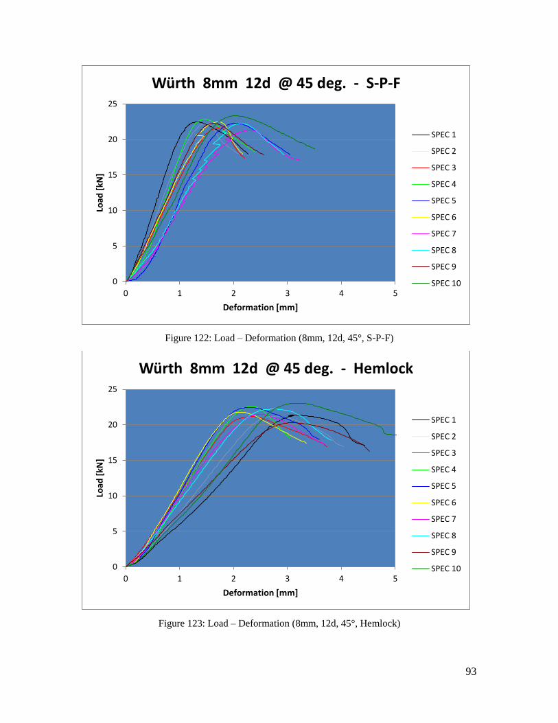
93
Figure 122: Load – Deformation (8mm, 12d, 45°, S-P-F)
Figure 123: Load – Deformation (8mm, 12d, 45°, Hemlock)
0
5
10
15
20
25
0 1 2 3 4 5
Load
[kN
]
Deformation [mm]
Würth 8mm 12d @ 45 deg. - S-P-F
SPEC 1
SPEC 2
SPEC 3
SPEC 4
SPEC 5
SPEC 6
SPEC 7
SPEC 8
SPEC 9
SPEC 10
0
5
10
15
20
25
0 1 2 3 4 5
Load
[kN
]
Deformation [mm]
Würth 8mm 12d @ 45 deg. - Hemlock
SPEC 1
SPEC 2
SPEC 3
SPEC 4
SPEC 5
SPEC 6
SPEC 7
SPEC 8
SPEC 9
SPEC 10

94
Figure 124: Load – Deformation (8mm, 12d, 30°, Douglas-fir)
Figure 125: Load – Deformation (8mm, 12d, 30°, S-P-F)
0
5
10
15
20
25
30
0 1 2 3 4 5 6
Load
[kN
]
Deformation [mm]
Würth 8mm 12d @ 30 deg. - Douglas-fir
SPEC 1
SPEC 2
SPEC 3
SPEC 4
SPEC 5
SPEC 6
SPEC 7
SPEC 8
SPEC 9
SPEC 10
0
5
10
15
20
25
30
0 1 2 3 4 5 6
Load
[kN
]
Deformation [mm]
Würth 8mm 12d @ 30 deg. - S-P-F
SPEC 1
SPEC 2
SPEC 3
SPEC 4
SPEC 5
SPEC 6
SPEC 7
SPEC 8
SPEC 9
SPEC 10

95
Figure 126: Load – Deformation (8mm, 12d, 30°, Hemlock)
Figure 127: Load – Deformation (8mm, 16d, 90°, Douglas-fir)
0
5
10
15
20
25
30
0 1 2 3 4 5 6
Load
[kN
]
Deformation [mm]
Würth 8mm 12d @ 30 deg. - Hemlock
SPEC 1
SPEC 2
SPEC 3
SPEC 4
SPEC 5
SPEC 6
SPEC 7
SPEC 8
SPEC 9
SPEC 10
0
5
10
15
20
25
30
0 1 2 3 4 5 6 7 8
Load
[kN
]
Deformation [mm]
Würth 8mm 16d @ 90 deg. - Douglas-fir
SPEC 1
SPEC 2
SPEC 3
SPEC 4
SPEC 5
SPEC 6
SPEC 7
SPEC 8
SPEC 9
SPEC 10

96
Figure 128: Load – Deformation (8mm, 16d, 90°, S-P-F)
Figure 129: Load – Deformation (8mm, 16d, 90°, Hemlock)
0
5
10
15
20
25
30
0 1 2 3 4 5 6 7 8
Load
[kN
]
Deformation [mm]
Würth 8mm 16d @ 90 deg. - S-P-F
SPEC 1
SPEC 2
SPEC 3
SPEC 4
SPEC 5
SPEC 6
SPEC 7
SPEC 8
SPEC 9
SPEC 10
0
5
10
15
20
25
30
0 1 2 3 4 5 6 7 8
Load
[kN
]
Deformation [mm]
Würth 8mm 16d @ 90 deg. - Hemlock
SPEC 1
SPEC 2
SPEC 3
SPEC 4
SPEC 5
SPEC 6
SPEC 7
SPEC 8
SPEC 9
SPEC 10
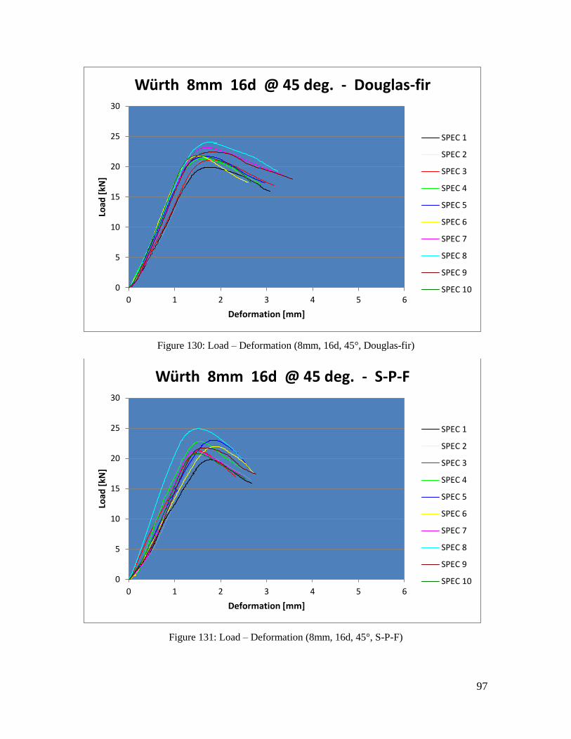
97
Figure 130: Load – Deformation (8mm, 16d, 45°, Douglas-fir)
Figure 131: Load – Deformation (8mm, 16d, 45°, S-P-F)
0
5
10
15
20
25
30
0 1 2 3 4 5 6
Load
[kN
]
Deformation [mm]
Würth 8mm 16d @ 45 deg. - Douglas-fir
SPEC 1
SPEC 2
SPEC 3
SPEC 4
SPEC 5
SPEC 6
SPEC 7
SPEC 8
SPEC 9
SPEC 10
0
5
10
15
20
25
30
0 1 2 3 4 5 6
Load
[kN
]
Deformation [mm]
Würth 8mm 16d @ 45 deg. - S-P-F
SPEC 1
SPEC 2
SPEC 3
SPEC 4
SPEC 5
SPEC 6
SPEC 7
SPEC 8
SPEC 9
SPEC 10

98
Figure 132: Load – Deformation (8mm, 16d, 45°, Hemlock)
Figure 133: Load – Deformation (8mm, 16d, 30°, Douglas-fir)
0
5
10
15
20
25
30
0 1 2 3 4 5 6
Load
[kN
]
Deformation [mm]
Würth 8mm 16d @ 45 deg. - Hemlock
SPEC 1
SPEC 2
SPEC 3
SPEC 4
SPEC 5
SPEC 6
SPEC 7
SPEC 8
SPEC 9
SPEC 10
0
5
10
15
20
25
0 1 2 3 4 5 6 7
Load
[kN
]
Deformation [mm]
Würth 8mm 16d @ 30 deg. - Douglas-fir
SPEC 1
SPEC 2
SPEC 3
SPEC 4
SPEC 5
SPEC 6
SPEC 7
SPEC 8
SPEC 9
SPEC 10

99
Figure 134: Load – Deformation (8mm, 16d, 30°, S-P-F)
Figure 135: Load – Deformation (8mm, 16d, 30°, Hemlock)
0
5
10
15
20
25
0 1 2 3 4 5 6 7
Load
[kN
]
Deformation [mm]
Würth 8mm 16d @ 30 deg. - S-P-F
SPEC 1
SPEC 2
SPEC 3
SPEC 4
SPEC 5
SPEC 6
SPEC 7
SPEC 8
SPEC 9
SPEC 10
0
5
10
15
20
25
0 1 2 3 4 5 6 7
Load
[kN
]
Deformation [mm]
Würth 8mm 16d @ 30 deg. - Hemlock
SPEC 1
SPEC 2
SPEC 3
SPEC 4
SPEC 5
SPEC 6
SPEC 7
SPEC 8
SPEC 9
SPEC 10

100
Figure 136: Load – Deformation (10mm, 4d, 90°, Douglas-fir)
Figure 137: Load – Deformation (10mm, 4d, 90°, S-P-F)
0
1
2
3
4
5
6
7
8
9
10
0 1 2 3 4 5 6
Load
[kN
]
Deformation [mm]
Würth 10mm 4d @ 90 deg. - Douglas-fir
SPEC 1
SPEC 2
SPEC 3
SPEC 4
SPEC 5
SPEC 6
SPEC 7
SPEC 8
SPEC 9
SPEC 10
0
1
2
3
4
5
6
7
8
9
10
0 1 2 3 4 5 6
Load
[kN
]
Deformation [mm]
Würth 10mm 4d @ 90 deg. - S-P-F
SPEC 1
SPEC 2
SPEC 3
SPEC 4
SPEC 5
SPEC 6
SPEC 7
SPEC 8
SPEC 9
SPEC 10

101
Figure 138: Load – Deformation (10mm, 4d, 90°, Hemlock)
Figure 139: Load – Deformation (10mm, 4d, 45°, Douglas-fir)
0
1
2
3
4
5
6
7
8
9
10
0 1 2 3 4 5 6
Load
[kN
]
Deformation [mm]
Würth 10mm 4d @ 90 deg. - Hemlock
SPEC 1
SPEC 2
SPEC 3
SPEC 4
SPEC 5
SPEC 6
SPEC 7
SPEC 8
SPEC 9
SPEC 10
0
2
4
6
8
10
12
14
0 1 2 3 4 5 6 7 8
Load
[kN
]
Deformation [mm]
Würth 10mm 4d @ 45 deg. - Douglas-fir
SPEC 1
SPEC 2
SPEC 3
SPEC 4
SPEC 5
SPEC 6
SPEC 7
SPEC 8
SPEC 9
SPEC 10

102
Figure 140: Load – Deformation (10mm, 4d, 45°, S-P-F)
Figure 141: Load – Deformation (10mm, 4d, 45°, Hemlock)
0
2
4
6
8
10
12
14
0 1 2 3 4 5 6 7 8
Load
[kN
]
Deformation [mm]
Würth 10mm 4d @ 45 deg. - S-P-F
SPEC 1
SPEC 2
SPEC 3
SPEC 4
SPEC 5
SPEC 6
SPEC 7
SPEC 8
SPEC 9
SPEC 10
0
2
4
6
8
10
12
14
0 1 2 3 4 5 6 7 8
Load
[kN
]
Deformation [mm]
Würth 10mm 4d @ 45 deg. - Hemlock
SPEC 1
SPEC 2
SPEC 3
SPEC 4
SPEC 5
SPEC 6
SPEC 7
SPEC 8
SPEC 9
SPEC 10

103
Figure 142: Load – Deformation (10mm, 4d, 30°, Douglas-fir)
Figure 143: Load – Deformation (10mm, 4d, 30°, S-P-F)
0
2
4
6
8
10
12
14
16
18
20
22
0 1 2 3 4 5
Load
[kN
]
Deformation [mm]
Würth 10mm 4d @ 30 deg. - Douglas-fir
SPEC 1
SPEC 2
SPEC 3
SPEC 4
SPEC 5
SPEC 6
SPEC 7
SPEC 8
SPEC 9
SPEC 10
0
2
4
6
8
10
12
14
16
18
20
22
0 1 2 3 4 5
Load
[kN
]
Deformation [mm]
Würth 10mm 4d @ 30 deg. - S-P-F
SPEC 1
SPEC 2
SPEC 3
SPEC 4
SPEC 5
SPEC 6
SPEC 7
SPEC 8
SPEC 9
SPEC 10

104
Figure 144: Load – Deformation (10mm, 4d, 30°, Hemlock)
Figure 145: Load – Deformation (10mm, 10d, 90°, Douglas-fir)
0
2
4
6
8
10
12
14
16
18
20
22
0 1 2 3 4 5
Load
[kN
]
Deformation [mm]
Würth 10mm 4d @ 30 deg. - Hemlock
SPEC 1
SPEC 2
SPEC 3
SPEC 4
SPEC 5
SPEC 6
SPEC 7
SPEC 8
SPEC 9
SPEC 10
0
5
10
15
20
25
30
35
0 1 2 3 4 5 6
Load
[kN
]
Deformation [mm]
Würth 10mm 10d @ 90 deg. - Douglas-fir
SPEC 1
SPEC 2
SPEC 3
SPEC 4
SPEC 5
SPEC 6
SPEC 7
SPEC 8
SPEC 9
SPEC 10

105
Figure 146: Load – Deformation (10mm, 10d, 90°, S-P-F)
Figure 147: Load – Deformation (10mm, 10d, 90°, Hemlock)
0
5
10
15
20
25
30
35
0 1 2 3 4 5 6
Load
[kN
]
Deformation [mm]
Würth 10mm 10d @ 90 deg. - S-P-F
SPEC 1
SPEC 2
SPEC 3
SPEC 4
SPEC 5
SPEC 6
SPEC 7
SPEC 8
SPEC 9
SPEC 10
0
5
10
15
20
25
30
35
0 1 2 3 4 5 6
Load
[kN
]
Deformation [mm]
Würth 10mm 10d @ 90 deg. - Hemlock
SPEC 1
SPEC 2
SPEC 3
SPEC 4
SPEC 5
SPEC 6
SPEC 7
SPEC 8
SPEC 9
SPEC 10

106
Figure 148: Load – Deformation (10mm, 10d, 45°, Douglas-fir)
Figure 149: Load – Deformation (10mm, 10d, 45°, S-P-F)
0
5
10
15
20
25
30
35
0 1 2 3 4 5 6
Load
[kN
]
Deformation [mm]
Würth 10mm 10d @ 45 deg. - Douglas-fir
SPEC 1
SPEC 2
SPEC 3
SPEC 4
SPEC 5
SPEC 6
SPEC 7
SPEC 8
SPEC 9
SPEC 10
0
5
10
15
20
25
30
35
0 1 2 3 4 5 6
Load
[kN
]
Deformation [mm]
Würth 10mm 10d @ 45 deg. - S-P-F
SPEC 1
SPEC 2
SPEC 3
SPEC 4
SPEC 5
SPEC 6
SPEC 7
SPEC 8
SPEC 9
SPEC 10

107
Figure 150: Load – Deformation (10mm, 10d, 45°, Hemlock)
Figure 151: Load – Deformation (10mm, 10d, 30°, Douglas-fir)
0
5
10
15
20
25
30
35
0 1 2 3 4 5 6
Load
[kN
]
Deformation [mm]
Würth 10mm 10d @ 45 deg. - Hemlock
SPEC 1
SPEC 2
SPEC 3
SPEC 4
SPEC 5
SPEC 6
SPEC 7
SPEC 8
SPEC 9
SPEC 10
0
5
10
15
20
25
30
35
0 1 2 3 4 5 6 7 8
Load
[kN
]
Deformation [mm]
Würth 10mm 10d @ 30 deg. - Douglas-fir
SPEC 1
SPEC 2
SPEC 3
SPEC 4
SPEC 5
SPEC 6
SPEC 7
SPEC 8
SPEC 9
SPEC 10

108
Figure 152: Load – Deformation (10mm, 10d, 30°, S-P-F)
Figure 153: Load – Deformation (10mm, 10d, 30°, Hemlock)
0
5
10
15
20
25
30
35
0 1 2 3 4 5 6 7 8
Load
[kN
]
Deformation [mm]
Würth 10mm 10d @ 30 deg. - S-P-F
SPEC 1
SPEC 2
SPEC 3
SPEC 4
SPEC 5
SPEC 6
SPEC 7
SPEC 8
SPEC 9
SPEC 10
0
5
10
15
20
25
30
35
0 1 2 3 4 5 6 7 8
Load
[kN
]
Deformation [mm]
Würth 10mm 10d @ 30 deg. - Hemlock
SPEC 1
SPEC 2
SPEC 3
SPEC 4
SPEC 5
SPEC 6
SPEC 7
SPEC 8
SPEC 9
SPEC 10

109
Figure 154: Load – Deformation (10mm, 12d, 90°, Douglas-fir)
Figure 155: Load – Deformation (10mm, 12d, 90°, S-P-F)
0
5
10
15
20
25
30
35
40
0 2 4 6 8 10
Load
[kN
]
Deformation [mm]
Würth 10mm 12d @ 90 deg. - Douglas-fir
SPEC 1
SPEC 2
SPEC 3
SPEC 4
SPEC 5
SPEC 6
SPEC 7
SPEC 8
SPEC 9
SPEC 10
0
5
10
15
20
25
30
35
40
0 2 4 6 8 10
Load
[kN
]
Deformation [mm]
Würth 10mm 12d @ 90 deg. - S-P-F
SPEC 1
SPEC 2
SPEC 3
SPEC 4
SPEC 5
SPEC 6
SPEC 7
SPEC 8
SPEC 9
SPEC 10

110
Figure 156: Load – Deformation (10mm, 12d, 90°, Hemlock)
Figure 157: Load – Deformation (10mm, 12d, 45°, Douglas-fir)
0
5
10
15
20
25
30
35
40
0 2 4 6 8 10
Load
[kN
]
Deformation [mm]
Würth 10mm 12d @ 90 deg. - Hemlock
SPEC 1
SPEC 2
SPEC 3
SPEC 4
SPEC 5
SPEC 6
SPEC 7
SPEC 8
SPEC 9
SPEC 10
0
5
10
15
20
25
30
35
0 1 2 3 4 5 6
Load
[kN
]
Deformation [mm]
Würth 10mm 12d @ 45 deg. - Douglas-fir
SPEC 1
SPEC 2
SPEC 3
SPEC 4
SPEC 5
SPEC 6
SPEC 7
SPEC 8
SPEC 9
SPEC 10

111
Figure 158: Load – Deformation (10mm, 12d, 45°, S-P-F)
Figure 159: Load – Deformation (10mm, 12d, 45°, Hemlock)
0
5
10
15
20
25
30
35
0 1 2 3 4 5 6
Load
[kN
]
Deformation [mm]
Würth 10mm 12d @ 45 deg. - S-P-F
SPEC 1
SPEC 2
SPEC 3
SPEC 4
SPEC 5
SPEC 6
SPEC 7
SPEC 8
SPEC 9
SPEC 10
0
5
10
15
20
25
30
35
0 1 2 3 4 5 6
Load
[kN
]
Deformation [mm]
Würth 10mm 12d @ 45 deg. - Hemlock
SPEC 1
SPEC 2
SPEC 3
SPEC 4
SPEC 5
SPEC 6
SPEC 7
SPEC 8
SPEC 9
SPEC 10

112
Figure 160: Load – Deformation (10mm, 12d, 30°, Douglas-fir)
Figure 161: Load – Deformation (10mm, 12d, 30°, S-P-F)
0
5
10
15
20
25
30
35
0 1 2 3 4 5 6 7 8
Load
[kN
]
Deformation [mm]
Würth 10mm 12d @ 30 deg. - Douglas-fir
SPEC 1
SPEC 2
SPEC 3
SPEC 4
SPEC 5
SPEC 6
SPEC 7
SPEC 8
SPEC 9
SPEC 10
0
5
10
15
20
25
30
35
0 1 2 3 4 5 6 7 8
Load
[kN
]
Deformation [mm]
Würth 10mm 12d @ 30 deg. - S-P-F
SPEC 1
SPEC 2
SPEC 3
SPEC 4
SPEC 5
SPEC 6
SPEC 7
SPEC 8
SPEC 9
SPEC 10
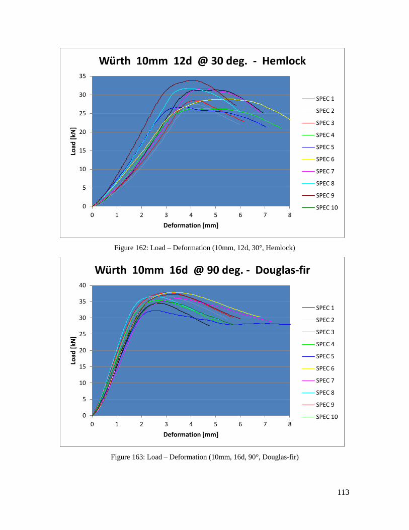
113
Figure 162: Load – Deformation (10mm, 12d, 30°, Hemlock)
Figure 163: Load – Deformation (10mm, 16d, 90°, Douglas-fir)
0
5
10
15
20
25
30
35
0 1 2 3 4 5 6 7 8
Load
[kN
]
Deformation [mm]
Würth 10mm 12d @ 30 deg. - Hemlock
SPEC 1
SPEC 2
SPEC 3
SPEC 4
SPEC 5
SPEC 6
SPEC 7
SPEC 8
SPEC 9
SPEC 10
0
5
10
15
20
25
30
35
40
0 1 2 3 4 5 6 7 8
Load
[kN
]
Deformation [mm]
Würth 10mm 16d @ 90 deg. - Douglas-fir
SPEC 1
SPEC 2
SPEC 3
SPEC 4
SPEC 5
SPEC 6
SPEC 7
SPEC 8
SPEC 9
SPEC 10
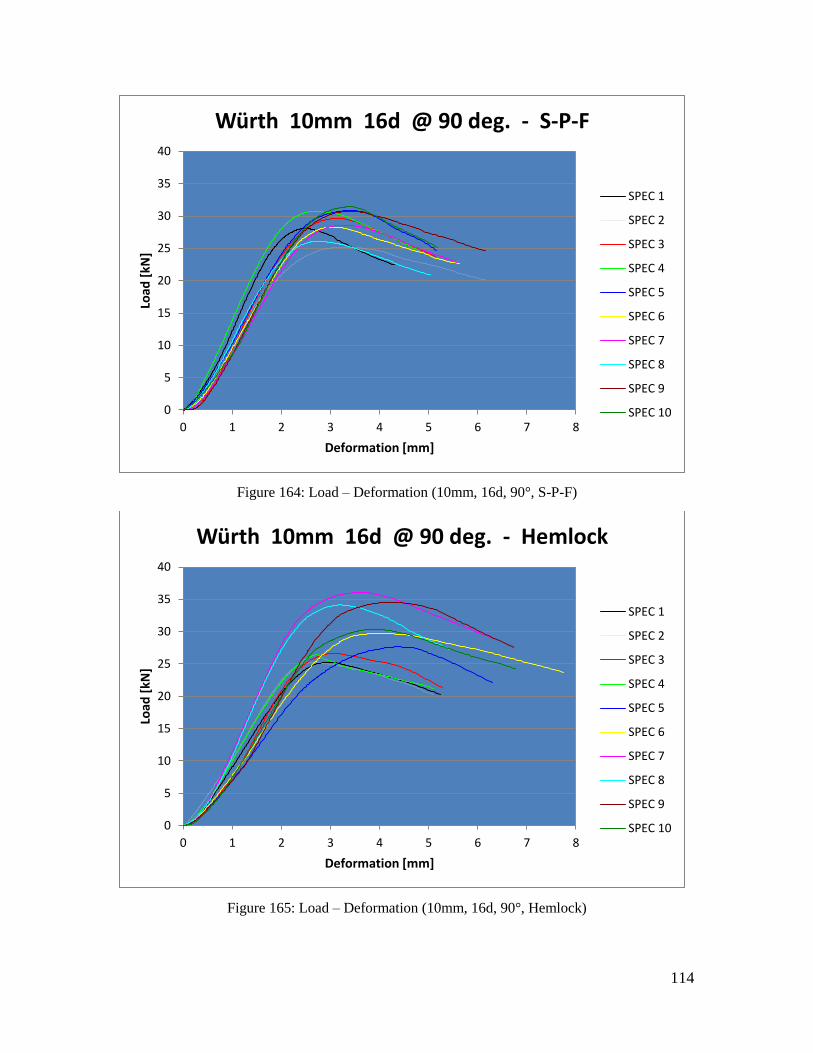
114
Figure 164: Load – Deformation (10mm, 16d, 90°, S-P-F)
Figure 165: Load – Deformation (10mm, 16d, 90°, Hemlock)
0
5
10
15
20
25
30
35
40
0 1 2 3 4 5 6 7 8
Load
[kN
]
Deformation [mm]
Würth 10mm 16d @ 90 deg. - S-P-F
SPEC 1
SPEC 2
SPEC 3
SPEC 4
SPEC 5
SPEC 6
SPEC 7
SPEC 8
SPEC 9
SPEC 10
0
5
10
15
20
25
30
35
40
0 1 2 3 4 5 6 7 8
Load
[kN
]
Deformation [mm]
Würth 10mm 16d @ 90 deg. - Hemlock
SPEC 1
SPEC 2
SPEC 3
SPEC 4
SPEC 5
SPEC 6
SPEC 7
SPEC 8
SPEC 9
SPEC 10

115
Figure 166: Load – Deformation (10mm, 16d, 45°, Douglas-fir)
Figure 167: Load – Deformation (10mm, 16d, 45°, S-P-F)
0
5
10
15
20
25
30
35
0 1 2 3 4 5 6
Load
[kN
]
Deformation [mm]
Würth 10mm 16d @ 45 deg. - Douglas-fir
SPEC 1
SPEC 2
SPEC 3
SPEC 4
SPEC 5
SPEC 6
SPEC 7
SPEC 8
SPEC 9
SPEC 10
0
5
10
15
20
25
30
35
0 1 2 3 4 5 6
Load
[kN
]
Deformation [mm]
Würth 10mm 16d @ 45 deg. - S-P-F
SPEC 1
SPEC 2
SPEC 3
SPEC 4
SPEC 5
SPEC 6
SPEC 7
SPEC 8
SPEC 9
SPEC 10

116
Figure 168: Load – Deformation (10mm, 16d, 45°, Hemlock)
Figure 169: Load – Deformation (10mm, 16d, 30°, Douglas-fir)
0
5
10
15
20
25
30
35
0 1 2 3 4 5 6
Load
[kN
]
Deformation [mm]
Würth 10mm 16d @ 45 deg. - Hemlock
SPEC 1
SPEC 2
SPEC 3
SPEC 4
SPEC 5
SPEC 6
SPEC 7
SPEC 8
SPEC 9
SPEC 10
0
5
10
15
20
25
30
35
40
0 1 2 3 4 5 6 7 8
Load
[kN
]
Deformation [mm]
Würth 10mm 16d @ 30 deg. - Douglas-fir
SPEC 1
SPEC 2
SPEC 3
SPEC 4
SPEC 5
SPEC 6
SPEC 7
SPEC 8
SPEC 9
SPEC 10

117
Figure 170: Load – Deformation (10mm, 16d, 30°, S-P-F)
Figure 171: Load – Deformation (10mm, 16d, 30°, Hemlock)
0
5
10
15
20
25
30
35
40
0 1 2 3 4 5 6 7 8
Load
[kN
]
Deformation [mm]
Würth 10mm 16d @ 30 deg. - S-P-F - Summary -
SPEC 1
SPEC 2
SPEC 3
SPEC 4
SPEC 5
SPEC 6
SPEC 7
SPEC 8
SPEC 9
SPEC 10
0
5
10
15
20
25
30
35
40
0 1 2 3 4 5 6 7 8
Load
[kN
]
Deformation [mm]
Würth 10mm 16d @ 30 deg. - Hemlock
SPEC 1
SPEC 2
SPEC 3
SPEC 4
SPEC 5
SPEC 6
SPEC 7
SPEC 8
SPEC 9
SPEC 10