
published separately and incorporating Corrigendum No. 1 ...
56
| | | | | | | | | | | | | | | | | | | | | | | | | | | | | | | | | | | | | | | | | | | | | | | | | | | | | | | | | | | | | | | | | | | | | | | | | | | | | | | | | | | | | | | | | | | | | | | | | | | | | | | | | | | | | | | | | | | | | | | | | | | | | | | | | BRITISH STANDARD BS 5950 : Part 6 : 1995 Implementing Amendment No. 1 not published separately and incorporating Corrigendum No. 1 ICS 91.080.10 NO COPYING WITHOUT BSI PERMISSION EXCEPT AS PERMITTED BY COPYRIGHT LAW Structural use of steelwork in building Part 6. Code of practice for design of light gauge profiled steel sheeting
Transcript of published separately and incorporating Corrigendum No. 1 ...
|||||||||||||||||||||||||||||||||||||||||||||||||||||||||||||||||||||||||||||||||||||||||||||||||||||||||||||||||||||||||||||||||
BRITISH STANDARD BS 5950 :Part 6 : 1995
ImplementingAmendment No. 1 notpublished separatelyand incorporatingCorrigendum No. 1
ICS 91.080.10
NO COPYING WITHOUT BSI PERMISSION EXCEPT AS PERMITTED BY COPYRIGHT LAW
Structural use ofsteelwork in building
Part 6. Code of practice for design oflight gauge profiled steel sheeting

This British Standard, havingbeen prepared under thedirection of Technical CommitteeB/525, was published under theauthority of the Standards Boardand comes into effect on15 March 1995
BSI 05-1999
The following BSI referencesrelate to the work on thisstandard:Committee reference B/525/31Draft for comment 88/10163 DC
ISBN 0 580 23271 9
BS 5950 : Part 6 : 1995 Issue 3, May 1999
Amendments issued since publication
Amd. No. Date Text affected
10239 January1999
Indicated by a sideline
10475corrigendum
May 1999 Indicated by a sideline
Committees responsible for thisBritish Standard
The preparation of this British Standard was entrusted by Technical CommitteeB/525, Building and civil engineering structures, to Subcommittee B/525/31, uponwhich the following bodies were represented:
Association of Consulting Engineers
British Cement Association
British Constructional Steelwork Association Ltd.
British Masonry Society
Building Employers' Confederation
Department of the Environment (Building Research Establishment)
Department of the Environment (Construction Directorate)
Department of Transport
Federation of Civil Engineering Contractors
Institution of Civil Engineers
Institution of Structural Engineers
National Council of Building Material Producers
Royal Institute of British Architects
Timber Research and Development Association
The following bodies were also represented in the drafting of the standard, through
subcommittees and panels:
British Industrial Fasteners' Federation
British Steel Industry
Cold Rolled Sections' Association
Construction Industry Research and Information Association
Department of the Environment (Specialist Services)
Health and Safety Executive
Steel Construction Institute
Welding Institute

Issue 2, May 1999 BS 5950 : Part 6 : 1995
BSI 05-1999 a
Summary of pages
The following table identifies the current issue of each page. Issue 1 indicates that a page has been introducedfor the first time by amendment. Subsequent issue numbers indicate an updated page. Vertical sidelining onreplacement pages indicates the most recent changes (amendment, addition, deletion).
Page Issue Page Issue
Front coverInside front coverab1234567891011121313a13b14151617181920212223242526
332blank322original2originaloriginaloriginaloriginaloriginaloriginal231blank2original2original3originaloriginal2original3222
27282929a29b3031323334353637383940414243444546474849505152Inside back coverBack cover
3221blankoriginaloriginal2original222original3originaloriginaloriginal2original222removedremovedremovedremovedremovedremovedoriginal2

b blank

Issue 3, May 1999 BS 5950 : Part 6 : 1995
BSI 05-1999 1
|
||||
Contents
Page
Code of practice
Foreword 3
Section 1. General
1.0 Introduction 4
1.1 Scope 4
1.2 References 4
1.3 Definitions 5
1.4 Symbols 6
Section 2. Limit state design
2.1 General principles and design methods 9
2.2 Loading 9
2.3 Ultimate limit state 10
2.4 Serviceability limit state 11
Section 3. Properties of materials and section properties
3.1 Range of thicknesses 12
3.2 Design thickness 12
3.3 Properties of materials 12
3.4 Calculation of section properties 13
Section 4. Local buckling
4.1 General 16
4.2 Maximum width to thickness ratios 17
4.3 Effective width for strength calculations 18
4.4 Effective cross section of a multiple-stiffened flange 24
4.5 Effective cross section of a multiple-stiffened web 27
4.6 Effective width for deflection calculations 30
Section 5. Design for lateral loading
5.1 General 32
5.2 Moment capacity 32
5.3 Web crushing resistance 36
5.4 Web shear capacity 38
5.5 Combined effects 39
5.6 Calculation of deflections 39
Section 6. Connections
6.1 General recommendations 41
6.2 Connections with screws and blind rivets 41
6.3 Powder actuated fasteners 42
6.4 Bolted connections 43
6.5 Weld detail and design 43
Section 7. Tests
7.1 General 44
7.2 Testing of sheeting 44
7.3 Text deleted
7.4 Text deleted
7.5 Text deleted
BS 5950 : Part 6 : 1995 Issue 2, January 1999
2 BSI 01-1999
|
Page
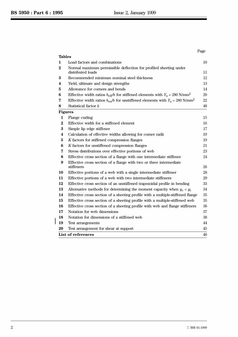
Tables
1 Load factors and combinations 10
2 Normal maximum permissible deflection for profiled sheeting underdistributed loads 11
3 Recommended minimum nominal steel thickness 12
4 Yield, ultimate and design strengths 13
5 Allowance for corners and bends 14
6 Effective width ratios beff/b for stiffened elements with Ys = 280 N/mm2 20
7 Effective width ratios beu/b for unstiffened elements with Ys = 280 N/mm2 22
8 Statistical factor k 48
Figures
1 Flange curling 15
2 Effective width for a stiffened element 16
3 Simple lip edge stiffener 17
4 Calculation of effective widths allowing for corner radii 19
5 K factors for stiffened compression flanges 19
6 K factors for unstiffened compression flanges 21
7 Stress distributions over effective portions of web 23
8 Effective cross section of a flange with one intermediate stiffener 24
9 Effective cross section of a flange with two or three intermediatestiffeners 26
10 Effective portions of a web with a single intermediate stiffener 28
11 Effective portions of a web with two intermediate stiffeners 29
12 Effective cross section of an unstiffened trapezoidal profile in bending 33
13 Alternative methods for determining the moment capacity when yc < yt 34
14 Effective cross section of a sheeting profile with a multiple-stiffened flange 35
15 Effective cross section of a sheeting profile with a multiple-stiffened web 35
16 Effective cross section of a sheeting profile with web and flange stiffeners 36
17 Notation for web dimensions 37
18 Notation for dimensions of a stiffened web 38
19 Test arrangements 44
20 Test arrangement for shear at support 45
List of references 46
Issue 2, January 1999 BS 5950 : Part 6 : 1995
BSI 01-1999 3
|
||
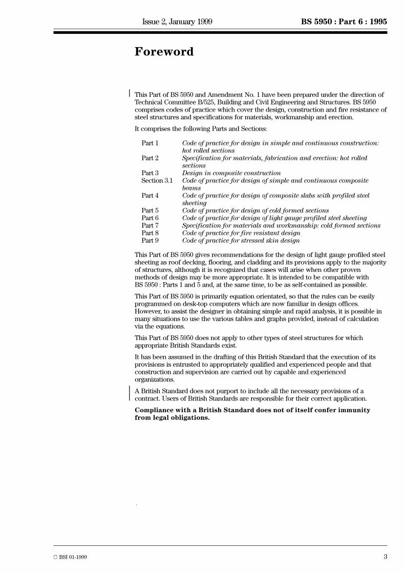
Foreword
This Part of BS 5950 and Amendment No. 1 have been prepared under the direction ofTechnical Committee B/525, Building and Civil Engineering and Structures. BS 5950comprises codes of practice which cover the design, construction and fire resistance ofsteel structures and specifications for materials, workmanship and erection.
It comprises the following Parts and Sections:
Part 1 Code of practice for design in simple and continuous construction:hot rolled sections
Part 2 Specification for materials, fabrication and erection: hot rolledsections
Part 3 Design in composite constructionSection 3.1 Code of practice for design of simple and continuous composite
beamsPart 4 Code of practice for design of composite slabs with profiled steel
sheetingPart 5 Code of practice for design of cold formed sectionsPart 6 Code of practice for design of light gauge profiled steel sheetingPart 7 Specification for materials and workmanship: cold formed sectionsPart 8 Code of practice for fire resistant designPart 9 Code of practice for stressed skin design
This Part of BS 5950 gives recommendations for the design of light gauge profiled steelsheeting as roof decking, flooring, and cladding and its provisions apply to the majorityof structures, although it is recognized that cases will arise when other provenmethods of design may be more appropriate. It is intended to be compatible withBS 5950 : Parts 1 and 5 and, at the same time, to be as self-contained as possible.
This Part of BS 5950 is primarily equation orientated, so that the rules can be easilyprogrammed on desk-top computers which are now familiar in design offices.However, to assist the designer in obtaining simple and rapid analysis, it is possible inmany situations to use the various tables and graphs provided, instead of calculationvia the equations.
This Part of BS 5950 does not apply to other types of steel structures for whichappropriate British Standards exist.
It has been assumed in the drafting of this British Standard that the execution of itsprovisions is entrusted to appropriately qualified and experienced people and thatconstruction and supervision are carried out by capable and experiencedorganizations.
A British Standard does not purport to include all the necessary provisions of acontract. Users of British Standards are responsible for their correct application.
Compliance with a British Standard does not of itself confer immunityfrom legal obligations.

4
BS 5950 : Part 6 : 1995 Section 1
Section 1. General
1.0 Introduction
1.0.1 Aims of economical structural design
The aim of structural design is to provide, with due regard to economy, a structure capable of fulfilling itsintended function and sustaining the specified loads for its intended life. The design should facilitate fabrication,erection and future maintenance.
Each part of the structure should be sufficiently robust and insensitive to the effects of minor incidental loadsapplied during service that the safety of other parts of the structure is not prejudiced.
Although the ultimate strength recommendations within this standard are to be regarded as limiting values, thepurpose in design should be to reach these limits at as many places as possible, consistent with the need torationalize sheeting profiles and thicknesses, in order to obtain the optimum combination of material andfabrication.
1.0.2 Accuracy of calculation
For the purpose of deciding whether a particular recommendation is satisfied, the final value, observed orcalculated, expressing the result of a test or analysis should be rounded off. The number of significant placesretained in the rounded off value should be the same as in the value given in the recommendation.
1.1 ScopeThis Part of BS 5950 gives recommendations for the design of light gauge profiled steel sheeting used as roofdecking, flooring and roof and wall cladding, including the design of profiled steel sheeting as permanentformwork for composite slabs.
It covers single and double skin cladding, but not the design of cladding elements which are not required to carrywind or snow loading. It is primarily intended for a net thickness of steel material up to 2 mm. It does not coverthe design of sections with large bend radii.
This Part of BS 5950 applies to profiled steel sheets which consist either of a series of stiffened or unstiffenedtrapezoidal flutes or of other ribbed profiles which behave in a substantially similar manner. Such sheets aregenerally made up of flat elements bounded either by free edges or by bends with included angles not exceeding1358. It also applies to profiled steel sheets which are embossed for use in composite slabs.
Only resistance to out-of-plane loading is covered in this Part of BS 5950. For resistance to in-plane loading bydiaphragm action see BS 5950 : Part 9.
For the design of composite slabs using profiled steel sheeting acting compositely with concrete see BS 5950 :Part 4.
NOTE.1. The recommendations given in this Part of BS 5950 assume that the standards of materials and workmanship are as specified inPart 7 of BS 5950.
1.2 References
1.2.1 Normative references
This Part of BS 5950 incorporates, by dated or undated reference, provisions from other publications. Thesenormative references are made at the appropriate places in the text and the cited publications are listed on theinside back cover. For dated references, only the edition cited applies: any subsequent amendments to orrevisions of the cited publication apply to this British Standard only when incorporated in the reference byamendment or revision. For undated references, the latest edition of the cited publication applies, together withany amendments.
1.2.2 Informative references
This British Standard refers to other publications that provide information or guidance. Editions of thesepublications current at the time of issue of this standard are listed on the inside back cover, but reference shouldbe made to the latest editions.

Section 1 Issue 2, January 1999 BS 5950 : Part 6 : 1995
BSI 01-1999 5
|
||
|||
1.3 DefinitionsFor the purposes of this Part of BS 5950 the following definitions apply.
1.3.1 capacity
Limit of force or moment which can be expected to be carried at a cross section without causing failure due toyielding, rupture or local buckling.
1.3.2 effective width
Flat width of an element that can be considered to resist compression effectively.
1.3.3 element
Distinct portion of the cross section of a sheet profile.
1.3.3.1 stiffened element
Flat element adequately supported at both longitudinal edges.
1.3.3.2 unstiffened element
Flat element adequately supported at only one longitudinal edge.
1.3.3.3 edge stiffened element
Flat element supported at one longitudinal edge by a web and at the other longitudinal edge by a lip or otheredge stiffener.
1.3.3.4 multiple-stiffened element
Element adequately supported at both longitudinal edges and having one or more intermediate stiffeners.
1.3.4 buckling resistance
Limit of force or moment that a sheet can withstand without buckling.
1.3.5 local buckling
Buckling of one or more of the compression elements of a cross section, characterized by the formation ofwaves or ripples along the sheet, which modifies the effectiveness of the cross section.
1.3.6 intermediate stiffeners
Folds or bends within a flange or web providing increased resistance to local buckling.
1.3.7 limit state
Condition beyond which a structure ceases to be fit for its intended use.
1.3.8 strength
Resistance to failure; specifically, limiting value for stress.
1.3.9 roof decking
Roof construction in which the load carrying profiled sheeting is located below insulation and waterproofinglayers.
1.3.10 profiled sheet
Sheet longitudinally formed with a cross section comprising regularly spaced trapezoidal or other ribbed profilesgenerally composed of flat elements, including substantially flat sheet with side overlapping profile, which cansupport load over a span.
1.3.11 intersection point
Point representing a corner for use in the calculation of element widths, generally the midpoint on a curvebetween adjacent flat elements (see figure 4) but optionally the intersection point of the elements if the bendradius is less than 5t.

6
BS 5950 : Part 6 : 1995 Section 1
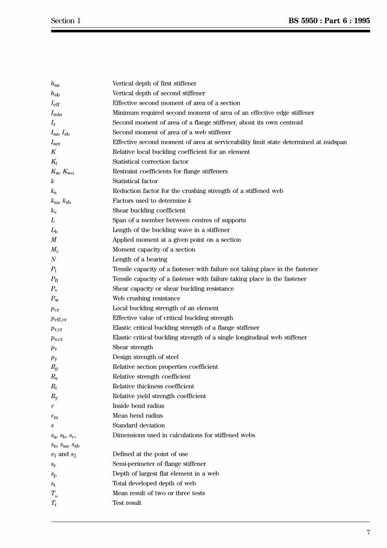
1.4 SymbolsFor the purposes of this Part of BS 5950, the following symbols apply:
Ar Total stiffened area comprising the flange stiffener plus the two adjacent effective portionsof the flange
Ar,ef Effective area of a flange stiffener
Asa, Asb Area of the folded web stiffener plus the two adjacent effective portions of the webstiffener
Asa,ef, Asb,ef Effective cross-sectional area of a web stiffener
a Distance between centres of holes in a perforated element
Bf Width of a flange for flange curling
b Flat width of an element (see figure 4)
bc Width subject to compression at ultimate limit state
bd Developed width of a stiffened element
beff Effective width of a compression element (see figure 4)
bef,1 to bef,n Effective widths of parts 1 to n of web (see figure 4)
bef,ser Effective width at serviceability limit state
bef,1,ser to bef,3,ser Effective widths at serviceability limit state
beu Effective width of an unstiffened compression element
bk b + br/2
bm Width of central portion of a stiffened flange, with two or more stiffeners
br Width of a stiffener
bt Width subject to tension at ultimate limit state
bt,ser Width subject to tension at serviceability limit state
Dp Overall depth of the profile
Dw Sloping distance between the intersection points of a web and flanges (see figure 4)
d Diameter of a fastener
dp Diameter of a perforation
dw Diameter of a washer
E Modulus of elasticity of steel
emax Maximum eccentricity of a web from its effective plane
emin Minimum eccentricity of a web from its effective plane
Fv Shear force
Fw Reaction or concentrated load on a web
fa Average stress in a flange
fc Applied compressive stress
fc,1 to fc,n Applied compressive edge stress
fser Compressive stress at serviceability limit state
f1,ser to fn,ser Compressive stress at serviceability limit state
ft Applied tensile stress
G Shear modulus of steel
g, g1 Corrections to element lengths for corner radii (see figure 4)
h Dw/b
ha Vertical distance from edge of a web stiffener to the compression flange
hb Vertical distance from edge of second stiffener to the compression flange
Section 1 BS 5950 : Part 6 : 1995
7
hsa Vertical depth of first stiffener
hsb Vertical depth of second stiffener
Ieff Effective second moment of area of a section
Imin Minimum required second moment of area of an effective edge stiffener
Ir Second moment of area of a flange stiffener, about its own centroid
Isa, Isb Second moment of area of a web stiffener
Iser Effective second moment of area at serviceability limit state determined at midspan
K Relative local buckling coefficient for an element
Kt Statistical correction factor
Kw, Kwo Restraint coefficients for flange stiffeners
k Statistical factor
ks Reduction factor for the crushing strength of a stiffened web
ksa, ksb Factors used to determine k
kv Shear buckling coefficient
L Span of a member between centres of supports
Lb Length of the buckling wave in a stiffener
M Applied moment at a given point on a section
Mc Moment capacity of a section
N Length of a bearing
Pt Tensile capacity of a fastener with failure not taking place in the fastener
Pft Tensile capacity of a fastener with failure taking place in the fastener
Pv Shear capacity or shear buckling resistance
Pw Web crushing resistance
pcr Local buckling strength of an element
peff,cr Effective value of critical buckling strength
pr,cr Elastic critical buckling strength of a flange stiffener
ps,cr Elastic critical buckling strength of a single longitudinal web stiffener
pv Shear strength
py Design strength of steel
Rp Relative section properties coefficient
Rs Relative strength coefficient
Rt Relative thickness coefficient
Ry Relative yield strength coefficient
r Inside bend radius
rm Mean bend radius
s Standard deviation
sa, sb, sc,
sn, ssa, ssb
Dimensions used in calculations for stiffened webs
s1 and s2 Defined at the point of use
sr Semi-perimeter of flange stiffener
sp Depth of largest flat element in a web
st Total developed depth of web
Tm
Mean result of two or three tests
Tr Test result

8
BS 5950 : Part 6 : 1995 Section 1
t Net thickness of steel material
teff Effective thickness of a perforated element
tnom Nominal thickness assumed in design
t1 Thickness of component under screw head
t2 Thickness of component remote from screw head
Us Minimum ultimate tensile strength of steel
u Maximum deflection of a flange towards the neutral axis due to flange curling
w Intensity of load at serviceability limit state
Ys Minimum yield strength of steel
y Distance from the flange to the neutral axis
yc Distance of the compression flange from the neutral axis
yt Distance of the tension flange from the neutral axis
a Coefficient of linear thermal expansion or elastic critical strength factor
b Reduction factor for stiffener effectiveness
e (280/py)0.5 (with py in N/mm2)
gf Overall load factor
gl Variability of loading factor
gm Material strength factor
gp Structural performance factor
d Deflection
h Perry coefficient
l, l1, lser Dimensionless quantities used in effective width calculations
lw, lwa, lwb Dimensionless quantities used in calculation of web shear capacity
u Angle between a web and a flange
n Poisson's ratio

Section 2 BS 5950 : Part 6 : 1995
9
1) In preparation.
Section 2. Limit state design
2.1 General principles and design methods
2.1.1 General
Profiled steel sheeting should be designed by considering the limit states at which it would become unfit for itsintended use, by applying appropriate factors for the ultimate limit state and the serviceability limit state.
Examples of limit states relevant to cold formed steel structures are given in table 1 of BS 5950 : Part 5 : 1987.
All relevant limit states should be considered, but usually it will be appropriate to design on the basis of strengthunder ultimate loading and then to check that deflection is not excessive under serviceability loading.
The overall factor in any design has to cover variability of:
Ð material strength gm;
Ð loading gl;
Ð structural performance gp.
In this Part of BS 5950 the material factor gm is taken as 1.0 for profiled steel sheet (see 3.3.2). Depending on thetype of load, values of gl and gp are assigned. The product of gl and gp is the factor gf by which the specifiedloads are to be multiplied in checking the strength and stability of a structure. Recommended values of gf aregiven in table 1.
2.1.2 Methods of design
2.1.2.1 General
The design should be carried out by one of the methods given in 2.1.2.2 to 2.1.2.4. In each case the details ofthe sheeting and its connections should be such as to realize the assumptions made in the design, withoutadversely affecting any other part of the structure.
2.1.2.2 Analytical design
In general, design should be based on an elastic analysis which assumes that the sheeting is either simplysupported or continuous over one or more intermediate supports, as appropriate, using the design equationsgiven in this code.
2.1.2.3 Design on the basis of tests
Alternatively, where design by calculation is not practical or is inappropriate, the strength and stiffness may beconfirmed by loading tests in accordance with section 7.
2.1.2.4 Design assisted by testing
For profiled sheets continuous over more than one span, a hybrid design method may be used, based on elasticsection properties and supplemented by information on the moment rotation properties of the section obtainedfrom testing or finite element analysis.
NOTE. An appropriate method of design assisted by testing is given in CIRIA Technical Note 116 [1].
2.2 Loading
2.2.1 General
All relevant loads should be considered separately and in such realistic combinations as to comprise the mostcritical effects on the element concerned. Loading conditions during erection should receive particular attention.
2.2.2 Dead, imposed and wind loading
Dead, imposed and wind loads should be determined in accordance with BS 6399 : Part 1, BS 6399 : Part 3 andCP 3 : Chapter V : Part 2 or BS 6399 : Part 21). Loads on agricultural buildings should be in accordance withBS 5502 : Part 22.

10
BS 5950 : Part 6 : 1995 Section 2
2.2.3 Roof loads
2.2.3.1 Minimum imposed roof loads
A distinction is made in BS 6399 : Part 3 between imposed loads on roofs with access and without access. Wherethere is regular traffic for the maintenance of services and other elements of the building the choice between thetwo alternative loading intensities given in BS 6399 : Part 3 should be carefully considered. Generally, the greaterloading requirement is recommended.
2.2.3.2 Equivalent line loads
For the purposes of this Part of BS 5950, the alternative concentrated loads of 0.9 kN and 1.8 kN, given inBS 6399 : Part 3, should be considered as equivalent to line loads of 1.5 kN/m and 3 kN/m respectively, in adirection transverse to the span of the sheeting. In multispan arrangements, the number and location of the lineloads should be that combination which produces the greatest bending moment in the sheeting, subject to therebeing not more than one line load per span.
2.2.4 Construction loads
Where it is likely that construction loads will occur on roof decking or roof cladding designed for the minimumimposed roof loads for a roof with no access (see 2.2.3.1), the line load of 1.5 kN/m referred to in 2.2.3.2 shouldbe increased to 2 kN/m.
2.2.5 Agricultural buildings
For buildings designed for reduced distributed imposed loads according to BS 5502 : Part 22, the line loads givenin 2.2.3.2 may be reduced in proportion.
2.2.6 Local roof loads
Profiled sheets used as roof decking or roof cladding should also be capable of supporting the local unfactoredload as defined in BS 5427.
2.3 Ultimate limit stateIn checking the strength of a profiled steel sheet, the loads should be multiplied by the relevant gf factors givenin table 1. The factored loads should be applied in the most unfavourable realistic combination for the sheetunder consideration.
The load capacity of each sheet and its connections, as determined by the relevant provisions of this Part ofBS 5950, should be such that the factored loads would not cause failure.
Table 1. Load factors and combinations
Loading Factor gf
Dead load 1.4
Dead load restraining uplift or overturning 1.0
Dead load acting with wind and imposed loads combined 1.2
Imposed load 1.6
Imposed load acting with wind load 1.2
Wind load 1.4
Wind load acting with imposed load 1.2
Forces due to temperature effects 1.2
NOTE 1. Dead loads may be taken as zero for wall cladding.NOTE 2. Construction loads are treated as imposed loads.
Section 2 BS 5950 : Part 6 : 1995
11
2.4 Serviceability limit state
2.4.1 Serviceability loads
In general, the serviceability loads should be taken as the full unfactored loads. When considering dead load plusimposed load plus wind load, only 80 % of the imposed load and wind load need be considered.
Construction loads should not be included in the serviceability loads.
2.4.2 Deflection
The deflections of a profiled steel sheet under serviceability loads should not impair the strength or efficiency ofthe sheeting or of its fixings or cause damage to flashings, insulation or waterproofing.
When checking the deflections the most adverse realistic combination and arrangement of serviceability loadsshould be assumed. Wind loading should normally be assumed to be uniform on all spans of multi-span sheeting.
Table 2 gives recommended deflection limits for various types of sheeting. Circumstances may arise wheregreater or lesser values would be more appropriate.
Table 2. Normal maximum permissible deflection1) forprofiled sheeting under distributed loads
Load condition Permissible deflection as a multiple ofspan
Roof cladding Wall cladding
Dead L/500 Ð
Dead and imposed L/200 Ð
Dead and wind L/90 L/1201) Excluding rooflights.

12 BSI 01-1999
BS 5950 : Part 6 : 1995 Issue 2, January 1999 Section 3
Section 3. Properties of materials and section properties
3.1 Range of thicknessesThe provisions of this Part of BS 5950 apply primarily to profiled steel sheet with a net thickness of steel basemetal of not more than 2 mm. The recommended minimum thickness for steels with a nominal yield strength Ysless than 280 N/mm2 is given in table 3. For profiles in steel of thickness less than the recommended minimum,the manufacturer of the profiled sheets should demonstrate adequate resistance to denting due to constructionand maintenance traffic.
Table 3. Recommended minimumnominal steel thickness
Use Minimum thickness mm
Roof decking 0.65
Roof cladding 0.65
Wall cladding 0.55
3.2 Design thicknessThe design thickness of the material should be taken as the nominal base metal thickness exclusive of coatings.
||
||||||
|||||||||||||
3.3 Properties of materials
3.3.1 General
This Part of BS 5950 covers the design of profiled sheeting made from steel supplied to BS 1449 : Part 1, BS 6830,BS EN 10025, BS EN 10130, BS EN 10143 or BS EN 10147. Other steels may be used provided that due allowanceis made for variation in properties, including ductility (see BS 5950 : Part 7).
NOTE. It is anticipated that BS 1449 and BS 6830 will eventually be superseded by further European Standards in the BS EN series.
3.3.2 Strength of steel
The design strength py should be taken as Ys but not greater than 0.84Us where:
Ys is the nominal yield strength (i.e. the higher yield strength, Reff, or in the case of material with noclearly defined yield, either the 0.2 % proof stress, Rp,0.2, or the stress at 0.5 % total elongation, Rt,0.5 asspecified in the relevant material standard);
Us is the nominal ultimate tensile strength (i.e. the minimum tensile strength, Rm as specified in therelevant material standard);
and Reff, Rp,0.2, Rt,0.5 and Rm are as defined in BS EN 10002-1.
For steels complying with one of the British Standards listed in Table 4, the values Reff, Rp,0.2, Rt,0.5 and Rmshould normally be taken as specified in the relevant product standard for the steel sheet or strip and used forthe formed sections. For information, the resulting values of Ys and Us are also given in Table 4 together withappropriate design strength py for the relevant grade.
NOTE. Formability grades have no guaranteed minimum strength, but can be expected to achieve a nominal yield strength of at least140 N/mm2.
Alternatively, for steels complying with any British Standard and supplied with specific inspection and testing toBS EN 10021, the values of Reff, Rp,0.2, Rt,0.5 and Rm may be based on the values declared in an inspectioncertificate in accordance with BS EN 10204.
Reference should be made to BS 5950 : Part 7 for recommendations concerning the testing regime required todetermine the characteristic properties of any steel not certified as complying with an appropriate BritishStandard.
The design strength py may be increased due to cold forming as given in 3.4.

Section 3 Issue 3, May 1999 BS 5950 : Part 6 : 1995
BSI 05-1999 13
|||||||||
|||
|
||||||
|||
||
|
|
|||
|||
||
||
||
|||||
|
||
|||||||||
|||||||
||||||||
||||||||
||||||||
|||||||||||
Table 4. Yield, ultimate and design strengths
Type of steel British Standard Grade Nominalyieldstrength1
Ys
Nominalultimatetensilestrength1
Us
DesignstrengthPy
N/mm2 N/mm2 N/mm2
Hot rolled steel sheet ofstructural quality
BS EN 10025S 235S 275S 355
235275355
360430510
235275355
Continuous hot dip zinccoated carbon steel sheetof structural quality
BS EN 10147
S 220 GS 250 GS 280 GS 320 GS 350 G
220250280320350
300330360390420
220250280320350
Hot rolled steel sheetbased on formability
BS 1449-1-1.8 HS 3 or HS 4 (170)2 (280)2 140
Hot rolled low carbonsteel sheet for coldforming
BS EN 10111 DD 11 or DD12
(170)2 Ð 140
Hot rolled high yieldstrength steel for coldformingThermomechanicallyrolled steels
BS EN 10149-2S 315 MCS 355 MCS 420 MC
315355420
390430480
3153554003
Hot rolled high yieldstrength steel for coldformingNormalized andnormalized rolled steels
BS EN 10149-3S 260 NCS 315 NCS 355 NCS 420 NC
260315355420
370430470530
260315355420
Cold rolled steel sheetbased on minimumstrength
BS 1449-1-1.5(CR)or
BS 1449-1-1.11(CS)
34/2037/2343/2550/3540/3043/3540F3043F35
200230250350300350300350
340370430500400430400430
200230250350300350300350
1 Nominal yield and ultimate tensile strengths are given for information only. For details see appropriate product standard.2 Figures in brackets are given for guidance only.3 Design strength limited to 0.84Us.
3.3.3 Other properties of steel
The following values for the elastic properties should be used:
± modulus of elasticity E = 205 kN/mm2
± shear modulus G = E/2.6
(i.e. G = 79 kN/mm2 approx.)
± Poisson's ratio n = 0.30
± coefficient of linear thermalexpansion
a = 123 1026/8C

13a BSI 05-1999
BS 5950 : Part 6 : 1995 Issue 1, May 1999 Section 3
||||||||
3.4 Calculation of section properties
3.4.1 Method of calculation
When calculating the section properties of sheet profiles, it may be assumed that the material is concentrated atthe mid-line of the sheet thickness, providing the flat width of all the elements is greater than r/0.15 or 20t,whichever is the greatest.
where:r is the inside bend radius
t is the net thickness of steel material.The presence of corners and bends should be allowed for as recommended in table 5.

blank 13b

14 BSI 01-1999
BS 5950 : Part 6 : 1995 Issue 2, January 1999 Section 3
|
|
Table 5. Allowance for corners and bends
Geometrical limit Basis for calculation
r# 5t Replace round corners by the intersects of the flat elements
5t < r# 0.04tE/py Use actual geometric configuration of cross section
r > 0.04tE/py For sections with large radii the carrying capacity is to be determined bytesting
Key
r is the inside bend radius;
t is the net thickness of steel material;
E is the modulus of elasticity;
py is the design strength.
NOTE 1. 0.04tE/py = 29.3t (280/py) approx. (py in N/mm2).NOTE 2. For the influence of corners on effective widths of flat elements see 4.3.2.
3.4.2 Gross section properties
When calculating the gross section properties of a sheet profile, holes for fasteners need not be deducted butallowance should be made for any large openings or arrays of small holes.
3.4.3 Net section properties
The net section properties of profiles with regular or irregular arrays of holes, other than holes required forfastening and filled with bolts or other mechanical fasteners, may be determined either by analytical methods(see 3.4.5) or by testing.
3.4.4 Profiles for composite slabs
Embossments and indentations designed to provide composite action with in-situ concrete may be ignored whencalculating the section properties of the sheeting profile.
3.4.5 Profiles with acoustic perforations
The section properties of sheet profiles incorporating a regular pattern of acoustic perforations should becalculated using the design equations for non-perforated sheet given in this Part of BS 5950, but replacing the netthickness t in the perforated zones by an effective thickness teff.
Except where more favourable values can be justified on the basis of tests, provided that the ratio dp/a is withinthe range 0.2# dp/a# 0.8, the effective thickness should be determined from
teff = t 1 2 (dp/a)2 }3/2
{where
dp is the diameter of the perforation;
a is the distance between centres of holes.
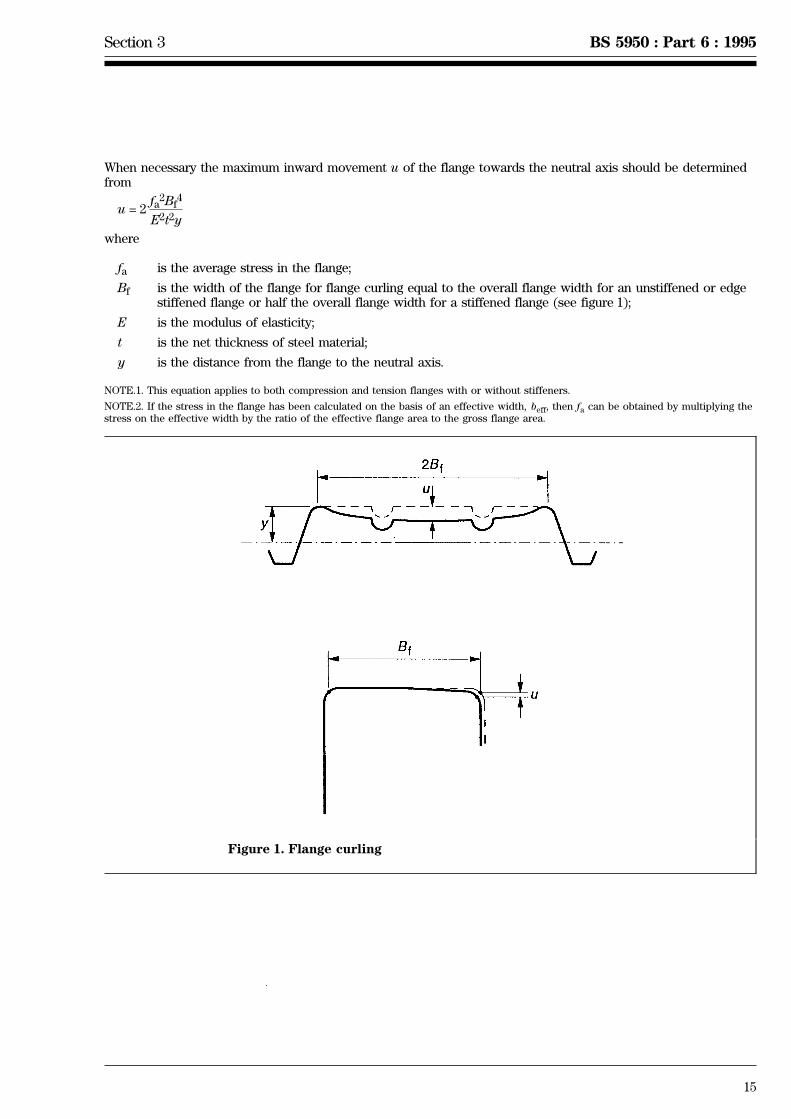
3.4.6 Flange curling
Profiles with flanges which have high width to thickness ratios Bf /t are liable to exhibit the type ofcross-sectional distortion known as `flange curling' shown in figure 1.
Provided that Bf /t is not greater than 250e the inward movement of each flange towards the neutral axis may beassumed to be less than 0.05Dp, where Dp is the overall depth of the profile, and its occurrence may beneglected for structural purposes.
Section 3 BS 5950 : Part 6 : 1995
15
When necessary the maximum inward movement u of the flange towards the neutral axis should be determinedfrom
u = 2fa
2Bf4
E2t2y
where
fa is the average stress in the flange;
Bf is the width of the flange for flange curling equal to the overall flange width for an unstiffened or edgestiffened flange or half the overall flange width for a stiffened flange (see figure 1);
E is the modulus of elasticity;
t is the net thickness of steel material;
y is the distance from the flange to the neutral axis.
NOTE.1. This equation applies to both compression and tension flanges with or without stiffeners.
NOTE.2. If the stress in the flange has been calculated on the basis of an effective width, beff, then fa can be obtained by multiplying thestress on the effective width by the ratio of the effective flange area to the gross flange area.
Figure 1. Flange curling

16 BSI 01-1999
BS 5950 : Part 6 : 1995 Issue 2, January 1998
Section 4. Local buckling
||
||||||||||||||||||||||||||
4.1 GeneralThe effects of local buckling in reducing the moment capacity and stiffness of a profiled steel sheet should beallowed for through the use of effective cross-sectional properties as described in 5.2 and 5.6. These should bedetermined making use of:
a) the effective widths of individual flat elements wholly or partly in compression; and
b) the effective areas of intermediate stiffeners.
For flat stiffened elements (1.3.3.1), the effective width consists of two portions, one adjacent to each edge(see figure 2).
For flat unstiffened elements (1.3.3.2), the whole of the effective width is located adjacent to the supported edge.
Figure 2. Effective width for a stiffened element
Section 4 BS 5950 : Part 6 : 1995
17
4.2 Maximum width to thickness ratios
4.2.1 General
For compression elements, the maximum values of element flat width to thickness ratio b/t covered by thedesign procedures given in this Part of BS 5950 are as follows:
a) stiffened elements with one longitudinal edge connected to a flange or web element and the other stiffenedby any stiffener satisfying 4.2.2: 90e;
b) stiffened elements with both longitudinal edges connected to other elements: 500e;
c) unstiffened compression elements: 60e
where
e is (280/py)0.5;
py is the design strength of the steel.
NOTE. Unstiffened compression elements that have width to thickness ratios b/t exceeding 30e and stiffened compression elements thathave b/t ratios exceeding 250e are likely to develop noticeable deformations at the full working load, without affecting the ability of themember to carry this load.
4.2.2 Edge stiffener
For a flat compression element to be considered a stiffened element, it should be supported along onelongitudinal edge by a web, and along the other by a web, or by a lip or other edge stiffener which has adequateflexural rigidity to maintain the straightness of this edge under load.
Irrespective of its shape, the second moment of area of an edge stiffener, about an axis through themid-thickness of the element to be stiffened, should not be less than Imin determined from
Imin =tb3
375
where
b is the width of the element to be stiffened;
t is the thickness.
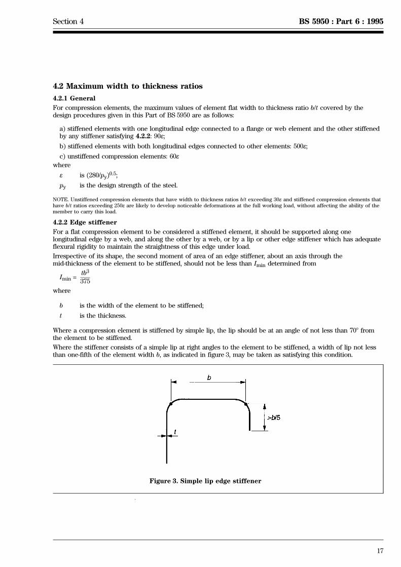
Where a compression element is stiffened by simple lip, the lip should be at an angle of not less than 708 fromthe element to be stiffened.
Where the stiffener consists of a simple lip at right angles to the element to be stiffened, a width of lip not lessthan one-fifth of the element width b, as indicated in figure 3, may be taken as satisfying this condition.
Figure 3. Simple lip edge stiffener
18 BSI 05-1999
BS 5950 : Part 6 : 1995 Issue 3, May 1999 Section 4
|
|
|
|
4.3 Effective width for strength calculations
4.3.1 Basic effective width
The ratio of the effective width beff to the flat width b of an element in compression should be determined fromthe following.
a) For fc/pcr# 0.123:
beff/b = 1
b) For fc/pcr > 0.123:
beff/b = 1 + 14 ({ 2 0.35)4√fc/pcr
20.2}
where
fc is the applied compressive stress in the effective element;
pcr is the local buckling strength of the element.
The local buckling strength pcr (in N/mm2) of an element should be determined from
pcr = 0.904EK(t/b)2
where
K is the relevant local buckling coefficient;
t is the net thickness of the steel material;
b is the flat width of the element.
The local buckling coefficient K depends upon the type of element and the geometry of the profile (see 4.3.3and 4.3.4).
4.3.2 Effect of bend radius
The effective width of a flat element should generally be calculated on the assumption that each element extendsto the mid-point of the corners.
When the inside bend radius r of a corner exceeds 5t, the effective width of each of the flat elements meeting atthat corner should be reduced by rmsin(u/2) (see figure 4).
NOTE. For the effect of bends and corners on the calculation of gross and net section properties see 3.4.1.
4.3.3 Effective width of a flat stiffened flange element
The effective width of a flat stiffened element (1.3.3.1) forming a compression flange should be determined inaccordance with 4.3.1, using the appropriate value of K.
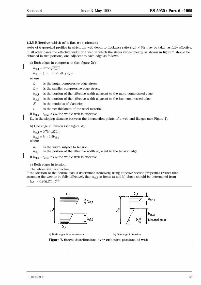
For flanges stiffened at both longitudinal edges the value of the buckling coefficient K may conservatively betaken as 4. Alternatively a more precise value of K may be obtained from figure 5 or determined from
K = 72 2 0.091h31.8h0.15 + h
where
h = Dw/b;
Dw is the sloping distance between the intersection points of a web and the flanges;
b is the flat width of the flange.
For stiffened flanges with K = 4 in profiles made of steel with yield strength Ys = 280 N/mm2, the effective widthbeff determined in accordance with 4.3.1 with fc = 280 N/mm2, may be obtained from the product of the ratiobeff/b given in table 6 and the flat width of the flange b.
For K values other than 4, or profiles made of steel with Ys other than 280 N/mm2, the effective width beff maybe obtained using table 6 with a modified b/t ratio, determined by multiplying the actual value of b/t by
√(4/K) (py/280)
Section 4 BS 5950 : Part 6 : 1995
19
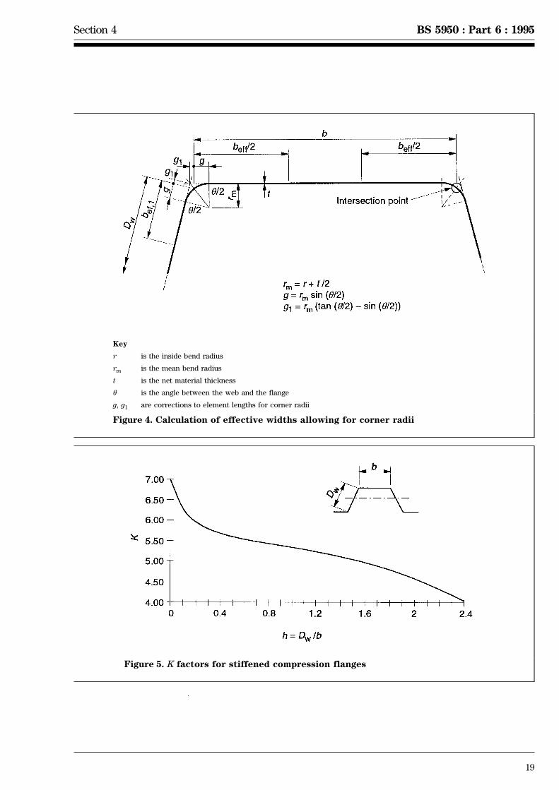
Key
r is the inside bend radius
rm is the mean bend radius
t is the net material thickness
u is the angle between the web and the flange
g, g1 are corrections to element lengths for corner radii
Figure 4. Calculation of effective widths allowing for corner radii
Figure 5. K factors for stiffened compression flanges

20
BS 5950 : Part 6 : 1995 Section 4
Table 6. Effective width ratios beff/b for stiffened elements with Ys = 280 N/mm2
b/t beff/b b/t beff/b b/t beff/b b/t beff/b
20 1 60 0.673 100 0.405 300 0.151
21 1 61 0.662 105 0.387 305 0.149
22 1 62 0.652 110 0.370 310 0.147
23 1 63 0.641 115 0.355 315 0.145
24 0.999 64 0.631 120 0.341 320 0.143
25 0.999 65 0.621 125 0.328 325 0.141
26 0.998 66 0.612 130 0.316 330 0.139
27 0.997 67 0.603 135 0.305 335 0.138
28 0.996 68 0.594 140 0.295 340 0.136
29 0.994 69 0.583 145 0.286 345 0.134
30 0.992 70 0.577 150 0.277 350 0.133
31 0.989 71 0.569 155 0.269 355 0.131
32 0.985 72 0.561 160 0.262 360 0.130
33 0.981 73 0.553 165 0.254 365 0.128
34 0.976 74 0.545 170 0.248 370 0.127
35 0.969 75 0.538 175 0.241 375 0.125
36 0.962 76 0.531 180 0.235 380 0.124
37 0.955 77 0.524 185 0.230 385 0.122
38 0.946 78 0.517 190 0.224 390 0.121
39 0.936 79 0.511 195 0.219 395 0.120
40 0.926 80 0.504 200 0.215 400 0.119
41 0.915 81 0.498 205 0.210 405 0.117
42 0.903 82 0.492 210 0.206 410 0.116
43 0.891 83 0.486 215 0.201 415 0.115
44 0.878 84 0.480 220 0.197 420 0.114
45 0.865 85 0.475 225 0.194 425 0.113
46 0.852 86 0.469 230 0.190 430 0.112
47 0.838 87 0.464 235 0.186 435 0.111
48 0.824 88 0.459 240 0.183 440 0.109
49 0.811 89 0.454 245 0.180 445 0.108
50 0.797 90 0.449 250 0.177 450 0.107
51 0.784 91 0.444 255 0.174 455 0.106
52 0.771 92 0.439 260 0.171 460 0.106
53 0.757 93 0.435 265 0.168 465 0.105
54 0.745 94 0.430 270 0.165 470 0.104
55 0.732 95 0.426 275 0.163 475 0.103
56 0.720 96 0.421 280 0.160 480 0.102
57 0.708 97 0.417 285 0.158 485 0.101
58 0.696 98 0.413 290 0.156 490 0.100
59 0.684 99 0.409 295 0.153 495 0.099
60 0.673 100 0.405 300 0.151 500 0.098

Section 4 Issue 2, January 1999 BS 5950 : Part 6 : 1995
BSI 01-1999 21
|
4.3.4 Effective width of a flat unstiffened flange element
The effective width beu of a flat unstiffened element (1.4.3.2) under uniform compression should be determinedfrom
beu = 0.89 beff + 0.11b
where
beff is determined from the basic effective width determined in accordance with 4.3.1;
b is the flat width of the element.
The value of K may conservatively be taken as 0.425 for any unstiffened element. Alternatively a more precisevalue of K may be obtained from figure 6 or determined from
K = 1.282 2 0.0025h20.8h2 + h
where
h = Dw/b;
Dw is the sloping distance between the intersection points of a web and the flanges;
For profiles made of steel with Ys equal to 280 N/mm2 and having K = 0.425, the effective width determined inaccordance with 4.3.1 and modified as above with fc = 280 N/mm2 may be obtained using table 7.
The effective width beff may be obtained from the product of the ratio beff/b given in table 7 and the actualelement width b.
For profiles made of steel with py other than 280 N/mm2, or having K values other than 0.425, the effective widthmay be obtained using table 7 by using a modified b/t ratio, determined by multiplying the actual value of b/t by(py/660K)0.5 where py is the design strength of the material.
Figure 6. K factors for unstiffened compression flanges

22
BS 5950 : Part 6 : 1995 Section 4
Table 7. Effective width ratios beu/b for unstiffened elements with Ys = 280 N/mm2
b/t beu/b b/t beu/b
1 1 31 0.489
2 1 32 0.477
3 1 33 0.466
4 1 34 0.456
5 1 35 0.447
6 1 36 0.438
7 1 37 0.429
8 0.999 38 0.422
9 0.997 39 0.414
10 0.991 40 0.407
11 0.980 41 0.400
12 0.961 42 0.394
13 0.935 43 0.388
14 0.903 44 0.382
15 0.868 45 0.376
16 0.831 46 0.371
17 0.794 47 0.366
18 0.759 48 0.361
19 0.726 49 0.356
20 0.696 50 0.352
21 0.668 51 0.348
22 0.643 52 0.343
23 0.619 53 0.339
24 0.598 54 0.336
25 0.578 55 0.332
26 0.560 56 0.328
27 0.544 57 0.325
28 0.528 58 0.322
29 0.514 59 0.319
30 0.501 60 0.315
Section 4 Issue 3, May 1999 BS 5950 : Part 6 : 1995
BSI 05-1999 23
|
|
|
4.3.5 Effective width of a flat web element
Webs of trapezoidal profiles in which the web depth to thickness ratio Dw/t# 70e may be taken as fully effective.
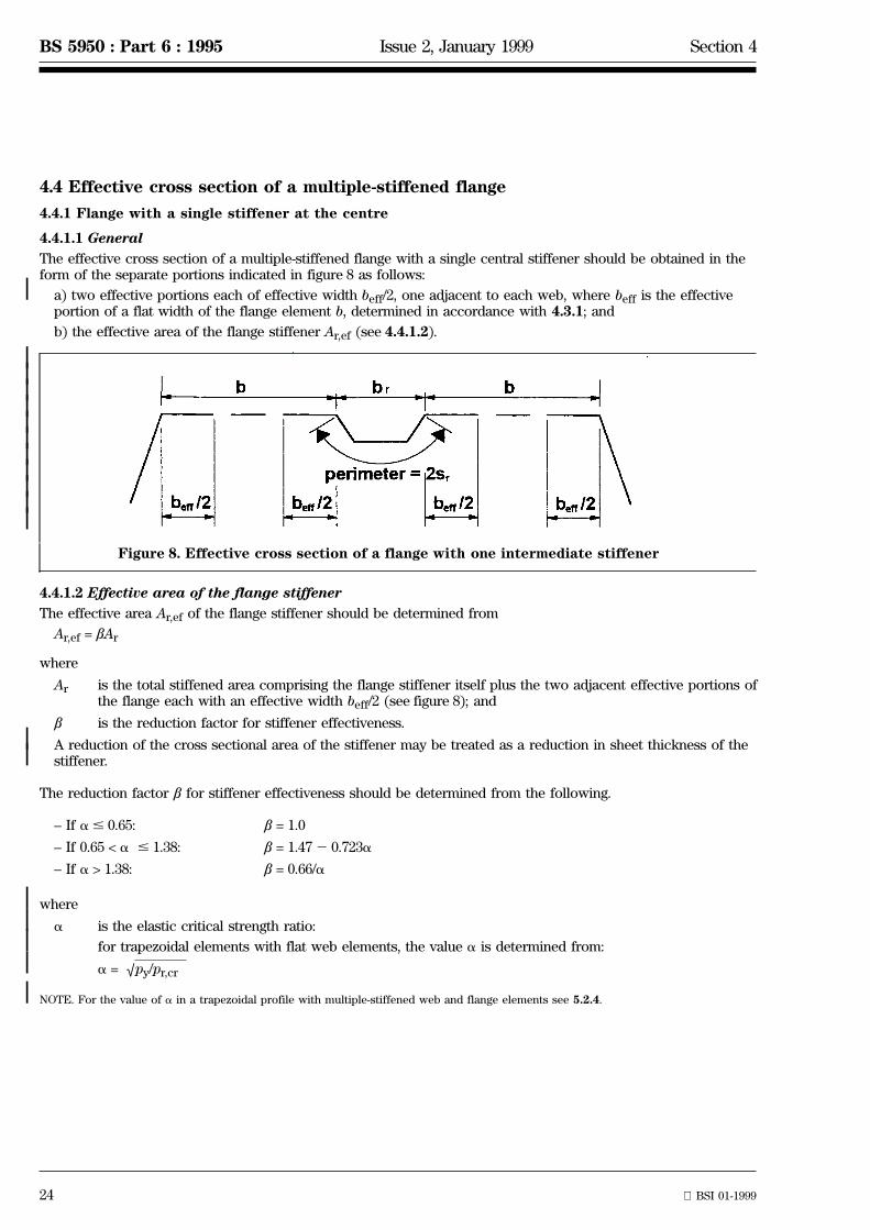
In all other cases the effective width of a web in which the stress varies linearly as shown in figure 7, should beobtained in two portions, one adjacent to each edge as follows.
a) Both edges in compression (see figure 7a):
bef,1 = 0.76t √E/fc,1
bef,2 = (1.52 0.5fc,2/fc,1)bef,1
where
fc,1 is the larger compressive edge stress;
fc,2 is the smaller compressive edge stress;
bef,1 is the portion of the effective width adjacent to the more compressed edge;
bef,2 is the portion of the effective width adjacent to the less compressed edge;
E is the modulus of elasticity;
t is the net thickness of the steel material.
If bef,1 + bef,2$ Dw the whole web is effective.
Dw is the sloping distance between the intersection points of a web and flanges (see Figure 4).
b) One edge in tension (see figure 7b):
bef,1 = 0.76t √E/fc,1
bef,3 = bt + 1.5bef,1
where
bt is the width subject to tension;bef,3 is the portion of the effective width adjacent to the tension edge.
If bef,1 + bef,3$ Dw the whole web is effective.
c) Both edges in tension:
The whole web is effective.If the location of the neutral axis is determined iteratively, using effective section properties (rather thanassuming the web to be fully effective), then bef,1 in items a) and b) above should be determined from
bef,1 = 0.95t(E/fc,1)0.5
a) Both edges in compression b) One edge in tension
Figure 7. Stress distributions over effective portions of web
24 BSI 01-1999
BS 5950 : Part 6 : 1995 Issue 2, January 1999 Section 4
|
|||||||||||
||
|||||
4.4 Effective cross section of a multiple-stiffened flange
4.4.1 Flange with a single stiffener at the centre
4.4.1.1 General
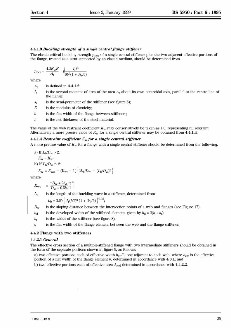
The effective cross section of a multiple-stiffened flange with a single central stiffener should be obtained in theform of the separate portions indicated in figure 8 as follows:
a) two effective portions each of effective width beff/2, one adjacent to each web, where beff is the effectiveportion of a flat width of the flange element b, determined in accordance with 4.3.1; and
b) the effective area of the flange stiffener Ar,ef (see 4.4.1.2).
Figure 8. Effective cross section of a flange with one intermediate stiffener
4.4.1.2 Effective area of the flange stiffener
The effective area Ar,ef of the flange stiffener should be determined from
Ar,ef = bAr
where
Ar is the total stiffened area comprising the flange stiffener itself plus the two adjacent effective portions ofthe flange each with an effective width beff/2 (see figure 8); and
b is the reduction factor for stiffener effectiveness.
A reduction of the cross sectional area of the stiffener may be treated as a reduction in sheet thickness of thestiffener.
The reduction factor b for stiffener effectiveness should be determined from the following.
± If a # 0.65: b = 1.0
± If 0.65 < a # 1.38: b = 1.472 0.723a
± If a > 1.38: b = 0.66/a
where
a is the elastic critical strength ratio:
for trapezoidal elements with flat web elements, the value a is determined from:
a = √py/pr,cr
NOTE. For the value of a in a trapezoidal profile with multiple-stiffened web and flange elements see 5.2.4.
Section 4 Issue 2, January 1999 BS 5950 : Part 6 : 1995
BSI 01-1999 25
|||
4.4.1.3 Buckling strength of a single central flange stiffener
The elastic critical buckling strength pr,cr of a single central stiffener plus the two adjacent effective portions ofthe flange, treated as a strut supported by an elastic medium, should be determined from
pr,cr =4.2KwE
Ar √ Irt3
8b3(1 + 3sr/b)
where
Ar is defined in 4.4.1.2;
Ir is the second moment of area of the area Ar about its own centroidal axis, parallel to the centre line ofthe flange;
sr is the semi-perimeter of the stiffener (see figure 8);
E is the modulus of elasticity;
b is the flat width of the flange between stiffeners;
t is the net thickness of the steel material.
The value of the web restraint coefficient Kw may conservatively be taken as 1.0, representing nil restraint.Alternatively a more precise value of Kw for a single central stiffener may be obtained from 4.4.1.4.
4.4.1.4 Restraint coefficient Kw for a single central stiffener
A more precise value of Kw for a flange with a single central stiffener should be determined from the following.
a) If Lb/Dw > 2:
Kw = Kwo
b) If Lb/Dw# 2:
Kw = Kwo2 (Kwo2 1) 2Lb/Dw 2 (Lb/Dw)2{ }where
Kwo = ;0.5
Dw + 2bd
Dw + 0.5bd
Lb is the length of the buckling wave in a stiffener, determined from
Lb = 3.65 Ir(b/t)3 (1 + 3sr/b)0.25
;{ }Dw is the sloping distance between the intersection points of a web and flanges (see Figure 17);
bd is the developed width of the stiffened element, given by bd = 2(b + sr);
br is the width of the stiffener (see figure 8);
b is the flat width of the flange element between the web and the flange stiffener.
4.4.2 Flange with two stiffeners
4.4.2.1 General
The effective cross section of a multiple-stiffened flange with two intermediate stiffeners should be obtained inthe form of the separate portions shown in figure 9, as follows:
a) two effective portions each of effective width beff/2, one adjacent to each web, where beff is the effectiveportion of a flat width of the flange element b, determined in accordance with 4.3.1; and
b) two effective portions each of effective area Ar,ef determined in accordance with 4.4.2.2.
26 BSI 01-1999
BS 5950 : Part 6 : 1995 Issue 2, January 1999 Section 4
||||||||||||||
|||
|
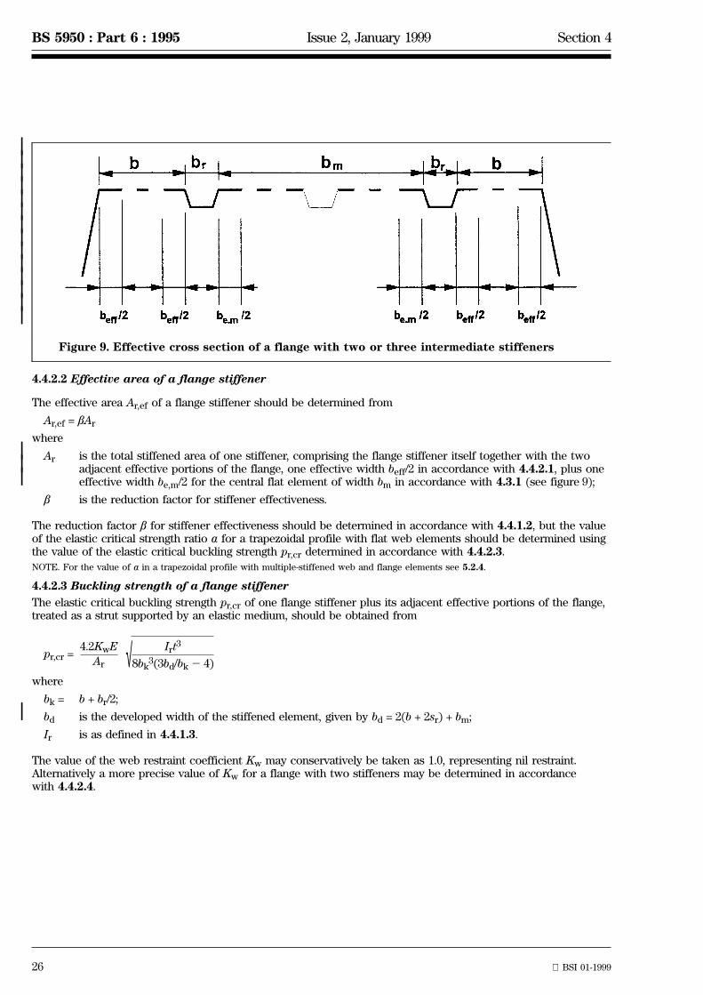
Figure 9. Effective cross section of a flange with two or three intermediate stiffeners
4.4.2.2 Effective area of a flange stiffener
The effective area Ar,ef of a flange stiffener should be determined from
Ar,ef = bAr
where
Ar is the total stiffened area of one stiffener, comprising the flange stiffener itself together with the twoadjacent effective portions of the flange, one effective width beff/2 in accordance with 4.4.2.1, plus oneeffective width be,m/2 for the central flat element of width bm in accordance with 4.3.1 (see figure 9);
b is the reduction factor for stiffener effectiveness.
The reduction factor b for stiffener effectiveness should be determined in accordance with 4.4.1.2, but the valueof the elastic critical strength ratio a for a trapezoidal profile with flat web elements should be determined usingthe value of the elastic critical buckling strength pr,cr determined in accordance with 4.4.2.3.
NOTE. For the value of a in a trapezoidal profile with multiple-stiffened web and flange elements see 5.2.4.
4.4.2.3 Buckling strength of a flange stiffener
The elastic critical buckling strength pr,cr of one flange stiffener plus its adjacent effective portions of the flange,treated as a strut supported by an elastic medium, should be obtained from
pr,cr =4.2KwE
Ar √ Irt3
8bk3(3bd/bk2 4)
where
bk = b + br/2;
bd is the developed width of the stiffened element, given by bd = 2(b + 2sr) + bm;
Ir is as defined in 4.4.1.3.
The value of the web restraint coefficient Kw may conservatively be taken as 1.0, representing nil restraint.Alternatively a more precise value of Kw for a flange with two stiffeners may be determined in accordancewith 4.4.2.4.

Section 4 Issue 3, May 1999 BS 5950 : Part 6 : 1995
BSI 05-1999 27
||
4.4.2.4 Restraint coefficient Kw for a flange with two stiffeners
A more precise value of Kw for a flange with two intermediate stiffeners may be determined from the following.
a) If Lb/Dw > 2:
Kw = Kwo
b) If Lb/Dw# 2:
Kw = Kwo2 (Kwo2 1){2Lb/Dw 2 (Lb/Dw)2}
where
Kwo = ;
(2bd + Dw) (3bd2 4bk)
bk(4bd2 6bk) + Dw(3bd2 4bk)
0.5
Lb is the length of the buckling wave in a stiffener, determined from
Lb = 3.65{Ir(bk/t)3(3bd/bk2 4)}0.25;
Dw is the sloping distance between the intersection points of a web and flanges (see Figure 4)
bk and bd are as defined in 4.4.2.3.
4.4.3 Flange with three or more stiffeners
When there are three or more intermediate flange stiffeners, only two flange stiffeners, one adjacent to each web,should be considered effective for calculation purposes. The effective portions of the flange are as shown infigure 9 determined in accordance with 4.4.2.
||||||||
4.5 Effective cross section of a multiple-stiffened web
4.5.1 Webs with a single stiffener
4.5.1.1 General
The effective cross section of an intermediately stiffened web under stress gradient, with a single longitudinalstiffener comprising two folds as shown in figure 10, should be obtained in the form of the separate portionsindicated in figure 10, as follows.
a) An effective portion of width bef,1 adjacent to the compression flange, where bef,1 is determined inaccordance with 4.3.5.
b) The effective area Asa,ef, determined in accordance with 4.5.1.2, based on the stiffened area Asa, where Asais the area of the folded web stiffener of width ssa plus the two adjacent effective portions of the web stiffener,with effective widths of bef,2 and bef,3 respectively (see figure 10a), determined from
bef,2 = bef,1 (1 + 0.5ha/yc)
bef,3 = bef,1 (1 + 0.5(ha + hsa)/yc)
where
ha and hsa are as shown on figure 10;
yc is the distance of the compression flange from the neutral axis.
If bef,1 + bef,2 > sa (see figure 10), the whole of sa is effective. In this case the value of bef,2 included in Asashould be reduced from bef,2 to bef,2sa/(bef,1 + bef,2).
If bef,3 + bef,n > sn (see figure 10), the whole of sn is effective. In this case the value of bef,3 included in Asashould be reduced from bef,3 to bef,3sn/(bef,3 + bef,n).
c) An effective portion of width bef,n adjacent to the neutral axis, determined from
bef,n = 1.5bef,1
d) The portion of the web in tension.
28 BSI 01-1999
BS 5950 : Part 6 : 1995 Issue 2, January 1999 Section 4
||||||||||||||||||||||||||||
|
||||
|
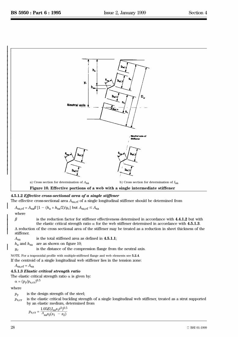
a) Cross section for determination of Asa b) Cross section for determination of Isa
Figure 10. Effective portions of a web with a single intermediate stiffener
4.5.1.2 Effective cross-sectional area of a single stiffener
The effective cross-sectional area Asa,ef of a single longitudinal stiffener should be determined from
Asa,ef = Asab [12 (ha + hsa/2)/yc] but Asa,ef # Asa
where
b is the reduction factor for stiffener effectiveness determined in accordance with 4.4.1.2 but withthe elastic critical strength ratio a for the web stiffener determined in accordance with 4.5.1.3.
A reduction of the cross sectional area of the stiffener may be treated as a reduction in sheet thickness of thestiffener.
Asa is the total stiffened area as defined in 4.5.1.1;
ha and hsa are as shown on figure 10;
yc is the distance of the compression flange from the neutral axis.
NOTE. For a trapezoidal profile with multiple-stiffened flange and web elements see 5.2.4.
If the centroid of a single longitudinal web stiffener lies in the tension zone:
Asa,ef = Asa
4.5.1.3 Elastic critical strength ratio
The elastic critical strength ratio a is given by:
a = (py/ps,cr)0.5
where
py is the design strength of the steel;
ps,cr is the elastic critical buckling strength of a single longitudinal web stiffener, treated as a strut supportedby an elastic medium, determined from
ps,cr =1.05E(Isas1t3)0.5
Asas2(s1 2 s2)

Section 4 Issue 2, January 1999 BS 5950 : Part 6 : 1995
BSI 01-1999 29
||||||||||||||||||||||
Isa is the second moment of area of the stiffener plus two effective portions each of width bef,1 about itsown centroidal axis parallel to the flat portions of the web (see figure 10b). In calculating Isa, anydifference in slope between the flat portions of the web on either side of the longitudinal stiffener maybe neglected;
s1 = 0.9(sa + ssa + sc);
s2 = s12 sa2 ssa/2;
t is the net material thickness.
4.5.2 Webs with two stiffeners
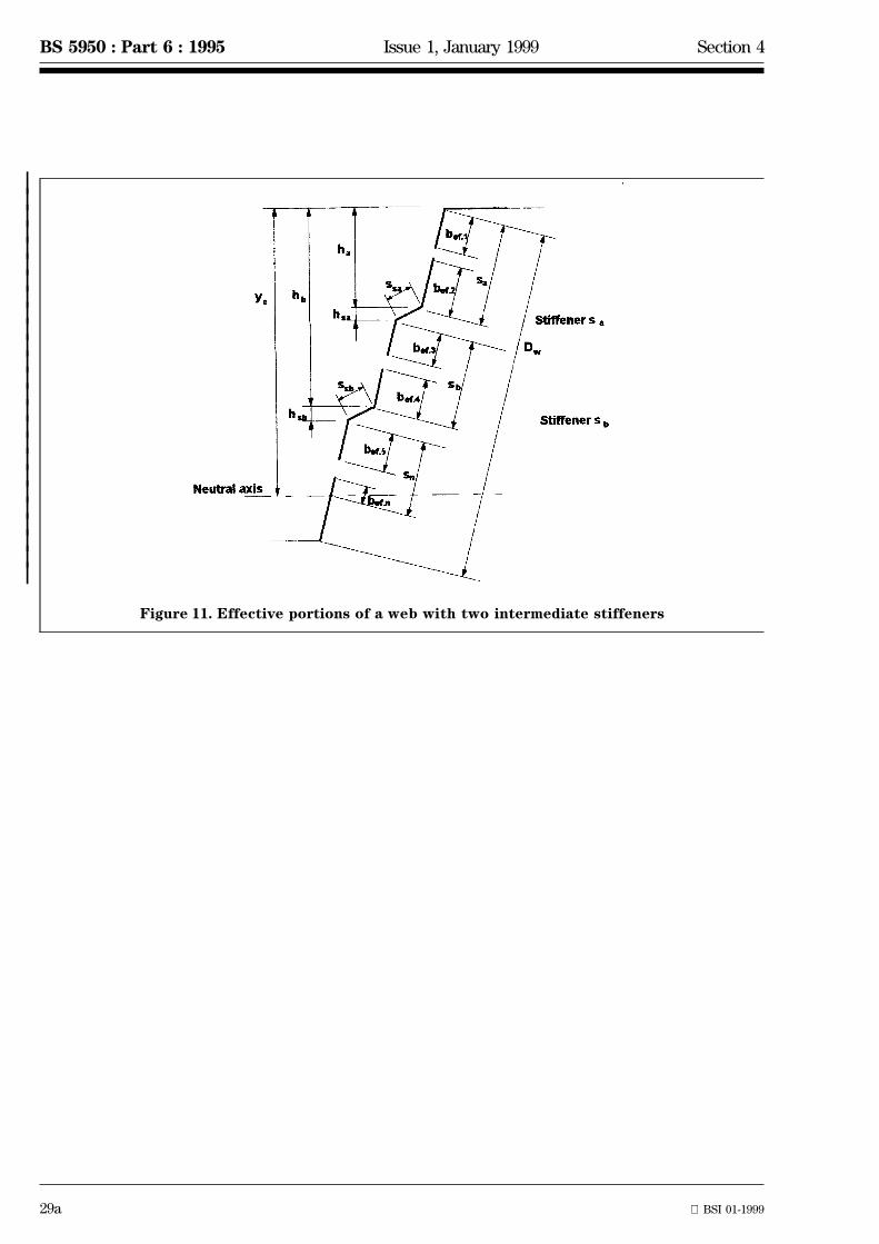
The effective cross section of an intermediately stiffened web under stress gradient, with two longitudinalstiffeners, each comprising two folds as shown in figure 11, should be obtained in the form of the separateportions indicated in figure 11, as follows:
a) an effective portion of width bef,1 adjacent to the compression flange, where bef,1 is determined inaccordance with 4.3.5;
b) the effective area Asa,ef, determined in accordance with 4.5.1.2 based on the area Asa of the folded webstiffener of width, ssa plus the two adjacent effective portions of the web with effective widths bef,2 and bef,3(see figure 11) respectively determined from
bef,2 = bef,1 (1 + 0.5ha/yc)
bef,3 = bef,1 {1 + 0.5(ha + hsa)yc}
where ha, hsa and yc are as shown in figure 11.
If bef,1 + bef,2 > sa (see figure 11) the whole of sa is effective. In this case the value of bef,2 included in Asashould be reduced from bef,2 to sa {bef,2/(bef,1 + bef,2)}.
If bef,3 + bef,4 > sb (see figure 11) the whole of sb is effective. In this case the value of bef,3 included in Asashould be reduced from bef,3 to sb {bef,3/(bef,3 + bef,4)}.
When calculating the value of ps,cr (4.5.1.3) s1 should be taken as sa + ssa + sb + 0.5(ssb + sc);
c) the effective area Asb,ef, based on the area Asb of the folded web stiffener of width, ssb, plus the twoadjacent effective portions of the web with effective widths bef,4 and bef,5 (see figure 11) respectivelydetermined from
bef,4 = bef,1 (1 + 0.5hb/yc)
bef,5 = bef,1 {1 + 0.5(hb + hsb)/yc}
where hb, hsb and yc are as shown in figure 11.
If bef,3 + bef,4 > sb (see figure 11) the whole of sb is effective. In this case the value of bef,4 included in Asbshould be reduced from bef,4 to sb {bef,4/(bef,3 + bef,4)}.
If bef,5 + bef,n > sn (see figure 11) the whole of sn is effective. In this case the value of bef,5 included in Asbshould be reduced from bef,5 to sn {bef,5/(bef,5 + bef,n)}.
It may be assumed that the area so determined is fully effective.
d) an effective portion of width bef,n determined in accordance with 4.5.1.1c);
e) the portion of the web in tension.
29a BSI 01-1999
BS 5950 : Part 6 : 1995 Issue 1, January 1999 Section 4
|||||||||||||||||||||||||
Figure 11. Effective portions of a web with two intermediate stiffeners

blank 29b
30
BS 5950 : Part 6 : 1995 Section 4
4.6 Effective width for deflection calculations
4.6.1 Flat flange elements
When calculating deflections, the serviceability limit state value of the basic effective width bef,ser for a stiffenedor unstiffened flat flange element should be determined from the following.
a) When lser# l1:
bef,ser = 1.27b/(lser)Ê but bef,ser# b
b) When l1 < lser# l:
bef,ser = bef,1,ser + (beff 2 bef,1,ser) (lser2 l1)/(l2 l1)
where
bef,1,ser = 1.27b/(l1)Ê but bef,1,ser# b;
l = ;2b/t
√K√(py/E)
l1 = 0.51 + 0.6l;
lser = ;2b/t
√K√(fser/E)
beff is the basic effective width determined in accordance with 4.3.1;
fser is the compressive stress in the effective element under serviceability loading;
K is the relevant local buckling coefficient determined in accordance with 4.3.3 or 4.3.4.
4.6.2 Flat web elements
When calculating deflections, webs of trapezoidal profiles with a web depth to thickness ratio Dw/t# 150e maybe taken as fully effective at the serviceability limit state.
Where this limit is exceeded, the serviceability limit state value of the effective width of a web in which thestress varies linearly, as shown in figure 7, should be obtained in two portions, one adjacent to each edge asfollows.
a) Both edges in compression (see figure 7a):
bef,1,ser = 0.95t √E/f1,ser
bef,2,ser = (1.52 0.5f2,ser /f1,ser)bef,1,ser
where
f1,ser is the larger compressive edge stress due to serviceability loading;
f2,ser is the smaller compressive edge stress due to serviceability loading;
bef,1,ser is the portion of the effective width adjacent to the more compressed edge;
bef,2,ser is the portion of the effective width adjacent to the less compressed edge.
b) One edge in tension (see figure 7b):
bef,1,ser = 0.95t √E/f1,ser
bef,3,ser = bt,ser + 1.5bef,1
where
bt,ser is the width subject to tension at serviceability limit state;
bef,3,ser is the portion of the effective width adjacent to the tension edge.
If bef,1,ser + bef,3,ser$ Dw the whole web is effective at the serviceability limit state.
c) Both edges in tension:
The whole web is effective at the serviceability limit state.
Section 4 BS 5950 : Part 6 : 1995
31
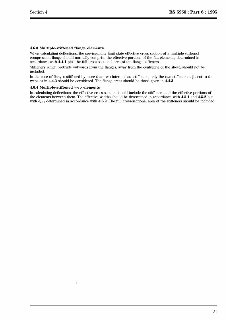
4.6.3 Multiple-stiffened flange elements
When calculating deflections, the serviceability limit state effective cross section of a multiple-stiffenedcompression flange should normally comprise the effective portions of the flat elements, determined inaccordance with 4.4.1 plus the full cross-sectional area of the flange stiffeners.
Stiffeners which protrude outwards from the flanges, away from the centreline of the sheet, should not beincluded.
In the case of flanges stiffened by more than two intermediate stiffeners, only the two stiffeners adjacent to thewebs as in 4.4.3 should be considered. The flange areas should be those given in 4.4.3.
4.6.4 Multiple-stiffened web elements
In calculating deflections, the effective cross section should include the stiffeners and the effective portions ofthe elements between them. The effective widths should be determined in accordance with 4.5.1 and 4.5.2 butwith bef,1 determined in accordance with 4.6.2. The full cross-sectional area of the stiffeners should be included.

32 BSI 01-1999
BS 5950 : Part 6 : 1995 Issue 2, January 1999
Section 5. Design for lateral loading
5.1 GeneralProfiled steel sheet should be designed for lateral loading by verifying the resistance of a single profile tobending, shear and crushing, acting separately and in combination.
The moment capacity should be determined using an effective cross section incorporating the effective widths ofthose elements partly or wholly in compression and the effective areas of any stiffeners. The moment capacityshould be based on the attainment of a limiting compressive stress equal to the design strength py in the effectivecross section. In cases where the tensile stress reaches the design strength py before the compressive stress,plastic redistribution of tensile stresses may be taken into account.
Where the use of effective section properties results in a web being only partly effective, improved propertiesmay be obtained through the use of iteration to locate the position of the neutral axis of the effective crosssection.
When calculating deflections under serviceability loading, the effective section properties of those elements partlyor wholly in compression should be determined from 4.6.
|
5.2 Moment capacity
5.2.1 Trapezoidal profiles without stiffeners
The effective cross section of a trapezoidal sheeting profile comprising flat web elements and flat flangeelements, as indicated in figure 12, should be determined as follows.
a) The neutral axis should initially be located on the basis of fully effective webs, a fully effective tensionflange and the effective width of compression flange determined in accordance with 4.3.3 using a compressivestress fc equal to the design strength py.
b) The effective widths of the webs should be determined in accordance with 4.3.5.
c) If the web is not fully effective, the position of the neutral axis may optionally be adjusted iteratively.
d) The moment capacity Mc should be determined from the following.
If yc$ yt:
Mc = pyIeff/yc
where
Ieff is the second moment of area of the effective cross section;
yc and yt are as shown on figure 12.
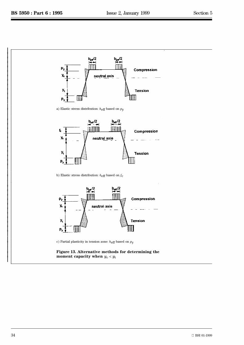
If yc < yt either:
1) adopt the elastic stress distribution shown in figure 13a in which the effective width of the compressionflange beff is determined from 4.3.4 using a compressive stress fc equal to the design strength py, thendetermine Mc from Mc = pyIeff/yt; or adopt the elastic stress distribution shown in figure 13b in which theeffective width of the compression flange beff is determined from 4.3.4 using the calculated compressivestress fc in the compression flange, then determine Mc from Mc = pyIeff/yt; or
2) adopt the stress distribution shown in figure 13c in which beff is based on py and sufficient plasticitydevelops in the tension zone to permit fc to reach py, adjusting the position of the neutral axis to maintainequilibrium between tension and compression on the effective cross section, then determine Mc from theresulting stress diagram.

Section 5 BS 5950 : Part 6 : 1995
33
Figure 12. Effective cross section of an unstiffened trapezoidal profile inbending
34 BSI 01-1999
BS 5950 : Part 6 : 1995 Issue 2, January 1999 Section 5
|||||||||||||||||||||||||||||||||||||||||||||
a) Elastic stress distribution: beff based on py
b) Elastic stress distribution: beff based on fc
c) Partial plasticity in tension zone: beff based on py
Figure 13. Alternative methods for determining themoment capacity when yc < yt
Section 5 Issue 2, January 1999 BS 5950 : Part 6 : 1995
BSI 01-1999 35
|
|
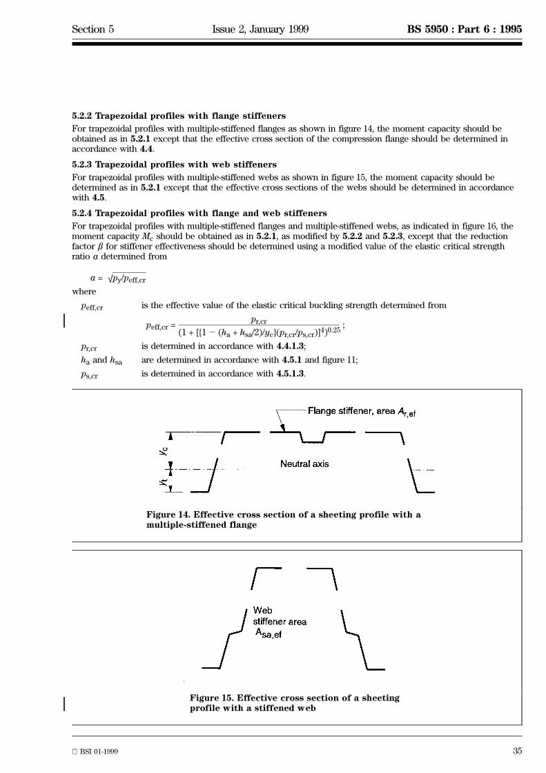
5.2.2 Trapezoidal profiles with flange stiffeners
For trapezoidal profiles with multiple-stiffened flanges as shown in figure 14, the moment capacity should beobtained as in 5.2.1 except that the effective cross section of the compression flange should be determined inaccordance with 4.4.
5.2.3 Trapezoidal profiles with web stiffeners
For trapezoidal profiles with multiple-stiffened webs as shown in figure 15, the moment capacity should bedetermined as in 5.2.1 except that the effective cross sections of the webs should be determined in accordancewith 4.5.
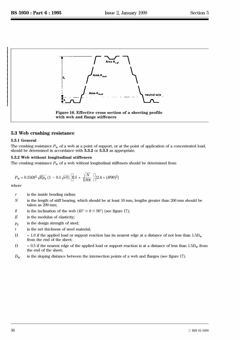
5.2.4 Trapezoidal profiles with flange and web stiffeners
For trapezoidal profiles with multiple-stiffened flanges and multiple-stiffened webs, as indicated in figure 16, themoment capacity Mc should be obtained as in 5.2.1, as modified by 5.2.2 and 5.2.3, except that the reductionfactor b for stiffener effectiveness should be determined using a modified value of the elastic critical strengthratio a determined from
a = √py/peff,cr
where
peff,cr is the effective value of the elastic critical buckling strength determined from
peff,cr = ;pr,cr
(1 + [{12 (ha + hsa/2)/yc}(pr,cr/ps,cr)]4)0.25
pr,cr is determined in accordance with 4.4.1.3;
ha and hsa are determined in accordance with 4.5.1 and figure 11;
ps,cr is determined in accordance with 4.5.1.3.
Figure 14. Effective cross section of a sheeting profile with amultiple-stiffened flange
Figure 15. Effective cross section of a sheetingprofile with a stiffened web
36 BSI 01-1999
BS 5950 : Part 6 : 1995 Issue 2, January 1999 Section 5
|||||||||||||
Figure 16. Effective cross section of a sheeting profilewith web and flange stiffeners
5.3 Web crushing resistance
5.3.1 General
The crushing resistance Pw of a web at a point of support, or at the point of application of a concentrated load,should be determined in accordance with 5.3.2 or 5.3.3 as appropriate.
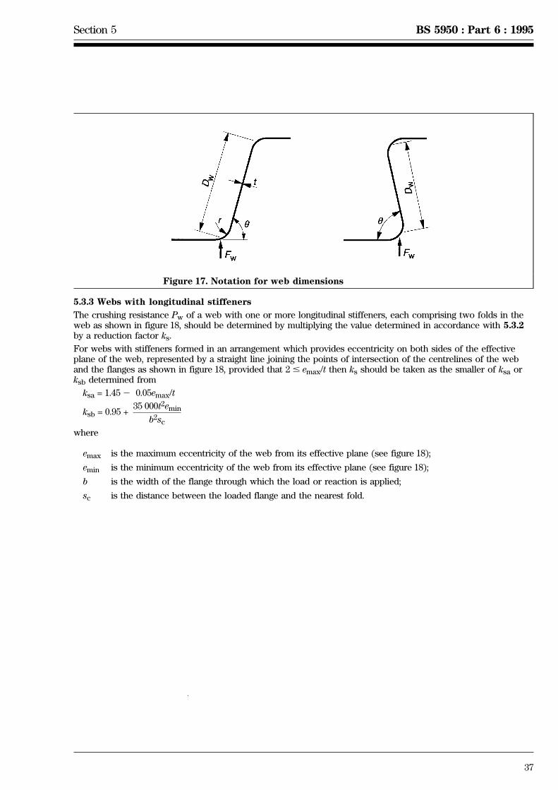
5.3.2 Web without longitudinal stiffeners
The crushing resistance Pw of a web without longitudinal stiffeners should be determined from
Pw = 0.15Vt2 (12 0.1 {2.4 + (u/90)2}√Epy √r/t)0.5 + √ N
50t
where
r is the inside bending radius;
N is the length of stiff bearing, which should be at least 10 mm, lengths greater than 200 mm should betaken as 200 mm;
u is the inclination of the web (458 # u# 908) (see figure 17);
E is the modulus of elasticity;
py is the design strength of steel;
t is the net thickness of steel material;
V = 1.0 if the applied load or support reaction has its nearest edge at a distance of not less than 1.5Dwfrom the end of the sheet;
V = 0.5 if the nearest edge of the applied load or support reaction is at a distance of less than 1.5Dw fromthe end of the sheet;
Dw is the sloping distance between the intersection points of a web and flanges (see figure 17).
Section 5 BS 5950 : Part 6 : 1995
37
Figure 17. Notation for web dimensions
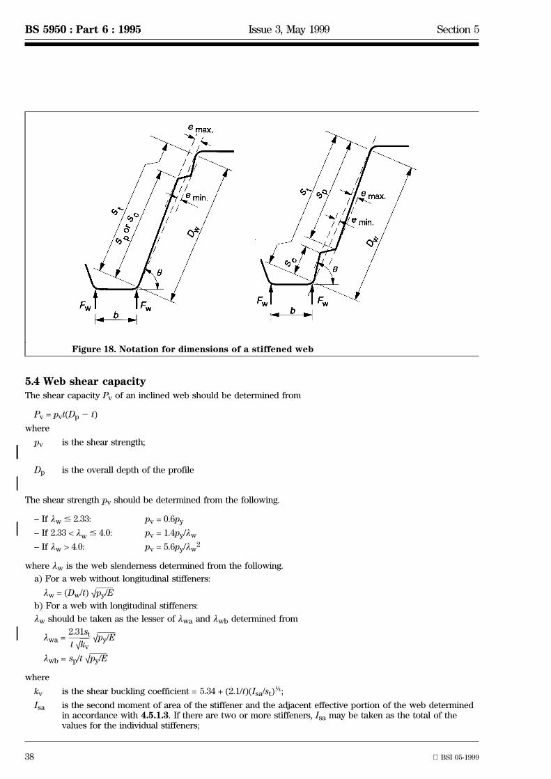
5.3.3 Webs with longitudinal stiffeners
The crushing resistance Pw of a web with one or more longitudinal stiffeners, each comprising two folds in theweb as shown in figure 18, should be determined by multiplying the value determined in accordance with 5.3.2by a reduction factor ks.
For webs with stiffeners formed in an arrangement which provides eccentricity on both sides of the effectiveplane of the web, represented by a straight line joining the points of intersection of the centrelines of the weband the flanges as shown in figure 18, provided that 2# emax/t then ks should be taken as the smaller of ksa orksb determined from
ksa = 1.452 0.05emax/t
ksb = 0.95 +35 000t2emin
b2sc
where
emax is the maximum eccentricity of the web from its effective plane (see figure 18);
emin is the minimum eccentricity of the web from its effective plane (see figure 18);
b is the width of the flange through which the load or reaction is applied;
sc is the distance between the loaded flange and the nearest fold.
38 BSI 05-1999
BS 5950 : Part 6 : 1995 Issue 3, May 1999 Section 5
Figure 18. Notation for dimensions of a stiffened web
||
|
|
|
5.4 Web shear capacityThe shear capacity Pv of an inclined web should be determined from
Pv = pvt(Dp2 t)
where
pv is the shear strength;
Dp is the overall depth of the profile
The shear strength pv should be determined from the following.
± If lw# 2.33: pv = 0.6py
± If 2.33 < lw# 4.0: pv = 1.4py/lw
± If lw > 4.0: pv = 5.6py/lw2
where lw is the web slenderness determined from the following.
a) For a web without longitudinal stiffeners:
lw = (Dw/t) √py/E
b) For a web with longitudinal stiffeners:
lw should be taken as the lesser of lwa and lwb determined from
lwa =2.31st
t √kv√py/E
lwb = sp/t √py/E
where
kv is the shear buckling coefficient = 5.34 + (2.1/t)(Isa/st)î;
Isa is the second moment of area of the stiffener and the adjacent effective portion of the web determinedin accordance with 4.5.1.3. If there are two or more stiffeners, Isa may be taken as the total of thevalues for the individual stiffeners;
Section 5 BS 5950 : Part 6 : 1995
39
st is the total developed depth of the web, as indicated in figure 18;
sp is the depth of the largest flat element in the web, as indicated in figure 18;
py is the design strength of steel.
5.5 Combined effects
5.5.1 Combined bending and web crushing
Webs of sheets subject to a combination of bending moment and concentrated load or reaction should be soproportioned that the following relationships are all satisfied:
Fw# Pw
M#Mc and
Fw/Pw + M/Mc# 1.25
where
Fw is the reaction or concentrated load;
Pw is the web crushing resistance from 5.3;
M is the moment at the point where Fw is applied;
Mc is the moment capacity from 5.2.
5.5.2 Combined bending and shear
Webs of sheets subject to a combination of bending moment and shear should be so proportioned that thefollowing relationship is satisfied:
(Fv/Pv)2 + (M/Mc)2# 1
where
Fv is the shear force;
Pv is the shear capacity from 5.4;
M is the moment at the same section as Fv;
Mc is the moment capacity from 5.2.
5.6 Calculation of deflections
5.6.1 General
Deflections should be calculated using elastic analysis. Due allowance should be made for the effects ofnon-uniform loading. The effective cross section for deflection calculations should be determined in accordancewith 4.6. The effective second moment of area Iser of the profile may be assumed to be constant throughouteach span.
Recommended deflection limits are given in 2.4.2.
5.6.2 Single spans
For a uniformly loaded single span, the deflection d should be determined from
d =5
384
wL4
EIser
where
w is the intensity of loading at the serviceability limit state;
L is the span between the centres of supports;
Iser is the effective second moment of area of the profile for serviceability loading, determined at midspan.
40
BS 5950 : Part 6 : 1995 Section 5
5.6.3 Sheeting continuous over two or more spans
5.6.3.1 Type of loading
When calculating deflections due to imposed gravity loads, the possibility of pattern loading between differentspans should be considered.
However when calculating deflections of profiled sheeting used as permanent shuttering for slabs the weight ofthe wet concrete may be taken as uniformly distributed on all spans.
Uniform loading on all spans may also be taken when calculating deflections of cladding and roof deckingsubject to wind load only.
5.6.3.2 Calculation of deflections
Unless a detailed analysis is undertaken the following approximations may be assumed to cover the extent ofloading most likely to be met in practice, providing that the spans do not vary by more than 15 % of the greatestspan.
The maximum deflection due to uniformly distributed load on all spans may be determined from
d =1
185
wL4
EIser
The maximum deflection d due to pattern loading may be determined from
d =3
384
wL4
EIser
where
L is the greatest span between centres of supports.
Section 6 BS 5950 : Part 6 : 1995
41
Section 6. Connections
6.1 General recommendations
6.1.1 General
Connections should be designed on the basis of a realistic assumption of the distribution of internal forces,having due regard to relative stiffness. This distribution should correspond with direct load paths through theelements of connections. It is essential that equilibrium is maintained with the factored external loads.
Ease of fabrication and erection should also be considered in the design of joints and splices. Attention shouldbe paid to the clearances necessary for tightening of fasteners, welding procedures, subsequent inspection,surface treatment and future maintenance.
The ductility of steel assists the distribution of forces within a joint. Residual stresses and stresses due totightening of fasteners and normal accuracy of fit-up need not be calculated.
6.1.2 Strength of individual fasteners
The strength of individual fasteners may be determined by calculation according to the following clauses.Alternatively the strength of individual fasteners may be determined by testing.
NOTE. Suitable procedures for the testing of fasteners are given in ECCS Publications No. 21 [2] and No. 42 [3].
6.1.3 Forces in individual fasteners
The shear forces in individual fasteners in a connection may be assumed to be equal.
6.1.4 Joints subject to vibration and/or load reversal
Where a connection is subject to impact or vibration, either welding, or fasteners which will not work loose inservice, should be used.
6.2 Connections with screws and blind rivets
6.2.1 General
The recommendations in 6.2 apply to self-tapping screws, including thread-forming, thread-cutting or self-drillingscrews, and to blind rivets. The diameter d of the screw or rivet is assumed to be in the range
3.0 mm# d# 7.5 mm
If components of different thickness are connected, the head of the screw or the preformed head of the rivetshould be in contact with the thinner component.
The diameter of pre-drilled holes should be strictly in accordance with the manufacturer's recommendations.
6.2.2 Minimum pitch
The distance between centres of fasteners should be not less than 3d.
6.2.3 Minimum edge and end distances
The distance from the centre of a fastener to the edge of any part should not be less than 3d. If the connection issubjected to force in one direction only, which is such as to cause shear of the fastener, the minimum edgedistance may be reduced to 1.5d or 10 mm, whichever is the smaller, in the direction normal to the force.
6.2.4 Calculation of capacity under tensile loading
Blind rivets should not be used to carry significant tensile forces.
For screws which carry significant tensile forces, the head of the screw, or washer if present, should have anoverall diameter dw of at least 8 mm and should have adequate rigidity.
The tensile capacity Pt at a screwed connection may be taken as the smallest of the following:
a) pulling of the connected material over the screw head or washer:
For connected material of thickness t1 less than 2.0 mm and washer size dw less than 25 mm
Pt = 1.1t1dwpy
where t1 is the thickness of the component in contact with the screw head or the preformed rivet head.
For other configurations the tensile capacity should be determined by testing.
42 BSI 01-1999
BS 5950 : Part 6 : 1995 Issue 2, January 1999 Section 6
|
b) pull out from the base material:
Provided that t2$ 0.9 mm:
Pt = 0.65dt2py
where t2 is the thickness of the component remote from the screw head or preformed rivet head.
c) tensile failure of the screw:
The tensile capacity Pft of the screw itself can only be determined by testing and should normally beguaranteed by the manufacturer. In order to avoid brittle failure the size of the fastener should be such that Pftis not less than 1.25Pt.
6.2.5 Capacity under shear loading
The recommendations for screws and blind rivets in shear given in BS 5950 : Part 5 should be used.
6.3 Powder actuated fasteners
6.3.1 General
The recommendations in 6.3 apply to powder actuated fasteners with a diameter d in the range:
3.5 mm# d# 4.5 mm
The thickness and strength grade of the components to be joined should be within the range recommended bythe fastener manufacturer. The base material into which powder actuated fasteners are fixed should normally behot finished steel sections with a minimum thickness of 6 mm unless specifically recommended otherwise by thefastener manufacturer.
6.3.2 Minimum pitch
The distance between centres of powder actuated fasteners should be not less than 4.5d.
6.3.3 Minimum edge and end distances
The distance from the centre of a powder actuated fastener to the edge of any component should not be lessthan 4.5d.
6.3.4 Calculation of capacity under tensile loading
Powder actuated fasteners should not be used to carry significant tensile forces unless they are used with asuitable washer of adequate rigidity and of minimum diameter 8 mm.
The tensile capacity Pt of a fastener may be taken as the smallest of the following:
a) pulling of the connected material over the washer:
For connected parts of thickness t1 less than 2.0 mm and for washer size dw less than 25 mm:
Pt = 1.1t1dwpy
where
t1 is the thickness of the component in contact with the washer;
dw is the diameter of the washer.
b) pull out from the base material:
The tensile capacity Pt should be determined by testing.
c) tensile failure of the fastener:
The tensile capacity Pft of the powder actuated fastener itself can only be determined by testing. It shouldnormally be taken as the value guaranteed by the fastener manufacturer. In order to avoid brittle failure thesize of the fastener should be such that Pft is not less than 1.25Pt.
6.3.5 Capacity under shear loading
The recommendations for powder actuated fasteners in shear given in BS 5950 : Part 5 should be followed.

Section 6 BS 5950 : Part 6 : 1995
43
6.4 Bolted connectionsThe design procedures for bolted connections in thin steel material given in BS 5950 : Part 5 should also be usedfor bolted connections between profiled steel sheets and for bolted connections between sheeting and supportingmembers.
6.5 Weld detail and designThe design procedures for welds in thin steel material given in BS 5950 : Part 5 should also be used for weldsbetween profiled steel sheets and for welds connecting sheeting to supporting members.
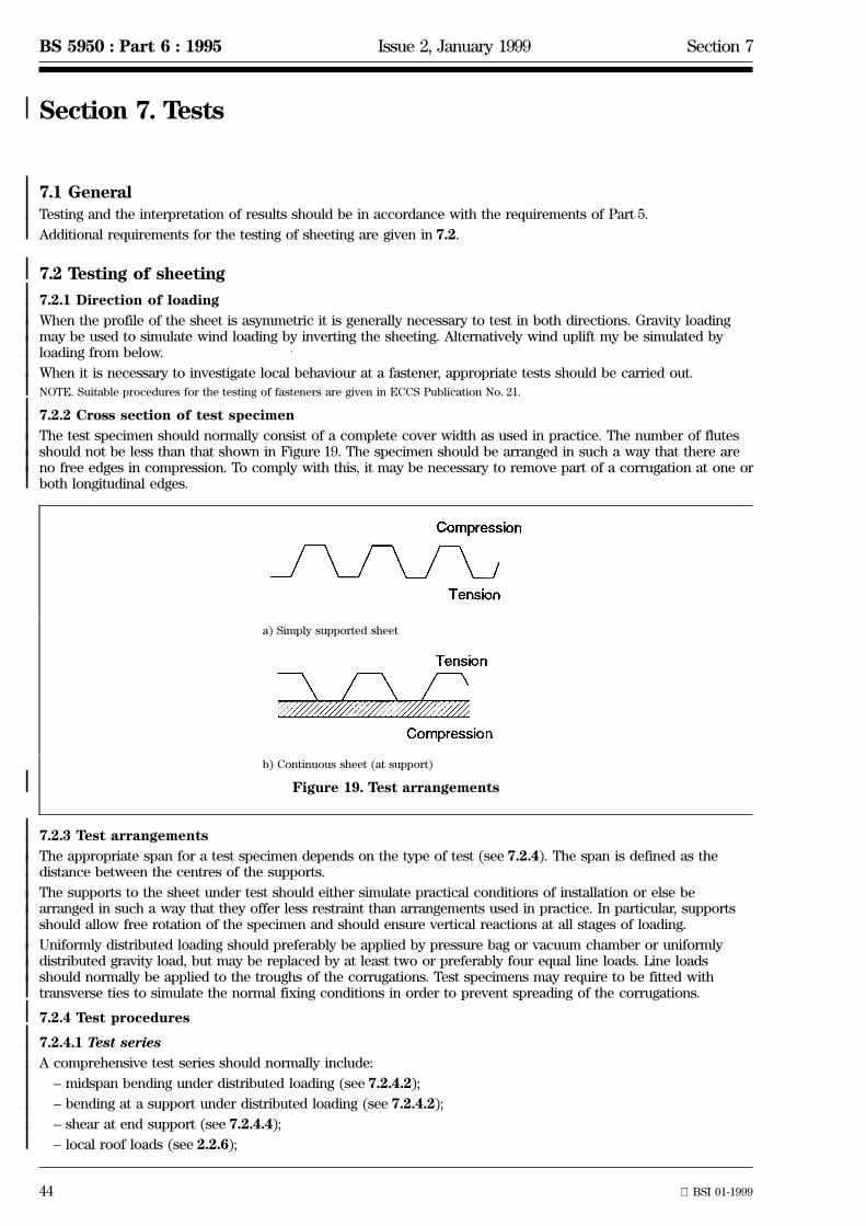
44 BSI 01-1999
BS 5950 : Part 6 : 1995 Issue 2, January 1999 Section 7
| Section 7. Tests
|||
7.1 GeneralTesting and the interpretation of results should be in accordance with the requirements of Part 5.
Additional requirements for the testing of sheeting are given in 7.2.
||||||||||||
|
|||||||||||||||||
7.2 Testing of sheeting
7.2.1 Direction of loading
When the profile of the sheet is asymmetric it is generally necessary to test in both directions. Gravity loadingmay be used to simulate wind loading by inverting the sheeting. Alternatively wind uplift my be simulated byloading from below.
When it is necessary to investigate local behaviour at a fastener, appropriate tests should be carried out.
NOTE. Suitable procedures for the testing of fasteners are given in ECCS Publication No. 21.
7.2.2 Cross section of test specimen
The test specimen should normally consist of a complete cover width as used in practice. The number of flutesshould not be less than that shown in Figure 19. The specimen should be arranged in such a way that there areno free edges in compression. To comply with this, it may be necessary to remove part of a corrugation at one orboth longitudinal edges.
a) Simply supported sheet
b) Continuous sheet (at support)
Figure 19. Test arrangements
7.2.3 Test arrangements
The appropriate span for a test specimen depends on the type of test (see 7.2.4). The span is defined as thedistance between the centres of the supports.
The supports to the sheet under test should either simulate practical conditions of installation or else bearranged in such a way that they offer less restraint than arrangements used in practice. In particular, supportsshould allow free rotation of the specimen and should ensure vertical reactions at all stages of loading.
Uniformly distributed loading should preferably be applied by pressure bag or vacuum chamber or uniformlydistributed gravity load, but may be replaced by at least two or preferably four equal line loads. Line loadsshould normally be applied to the troughs of the corrugations. Test specimens may require to be fitted withtransverse ties to simulate the normal fixing conditions in order to prevent spreading of the corrugations.
7.2.4 Test procedures
7.2.4.1 Test series
A comprehensive test series should normally include:
± midspan bending under distributed loading (see 7.2.4.2);
± bending at a support under distributed loading (see 7.2.4.2);
± shear at end support (see 7.2.4.4);
± local roof loads (see 2.2.6);
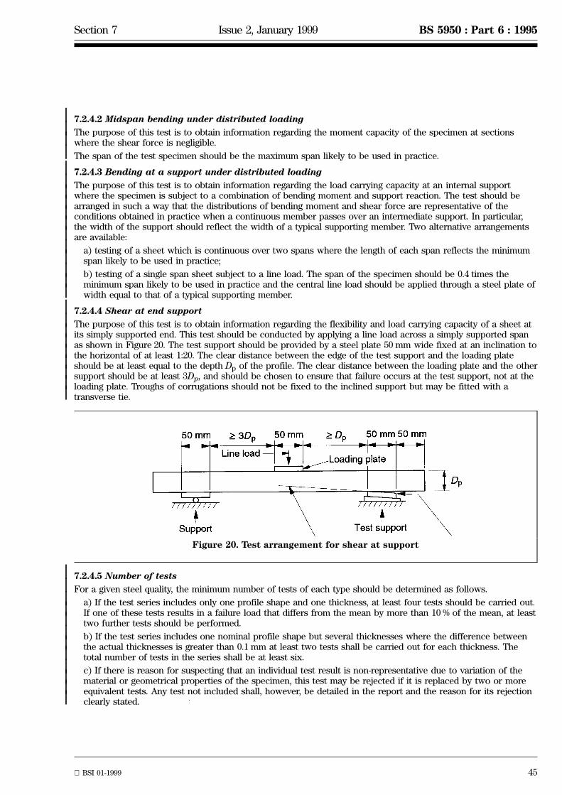
Section 7 Issue 2, January 1999 BS 5950 : Part 6 : 1995
BSI 01-1999 45
|||||||||||||||||||||||||
||||||||||||
7.2.4.2 Midspan bending under distributed loading
The purpose of this test is to obtain information regarding the moment capacity of the specimen at sectionswhere the shear force is negligible.
The span of the test specimen should be the maximum span likely to be used in practice.
7.2.4.3 Bending at a support under distributed loading
The purpose of this test is to obtain information regarding the load carrying capacity at an internal supportwhere the specimen is subject to a combination of bending moment and support reaction. The test should bearranged in such a way that the distributions of bending moment and shear force are representative of theconditions obtained in practice when a continuous member passes over an intermediate support. In particular,the width of the support should reflect the width of a typical supporting member. Two alternative arrangementsare available:
a) testing of a sheet which is continuous over two spans where the length of each span reflects the minimumspan likely to be used in practice;
b) testing of a single span sheet subject to a line load. The span of the specimen should be 0.4 times theminimum span likely to be used in practice and the central line load should be applied through a steel plate ofwidth equal to that of a typical supporting member.
7.2.4.4 Shear at end support
The purpose of this test is to obtain information regarding the flexibility and load carrying capacity of a sheet atits simply supported end. This test should be conducted by applying a line load across a simply supported spanas shown in Figure 20. The test support should be provided by a steel plate 50 mm wide fixed at an inclination tothe horizontal of at least 1:20. The clear distance between the edge of the test support and the loading plateshould be at least equal to the depth Dp of the profile. The clear distance between the loading plate and the othersupport should be at least 3Dp, and should be chosen to ensure that failure occurs at the test support, not at theloading plate. Troughs of corrugations should not be fixed to the inclined support but may be fitted with atransverse tie.
Figure 20. Test arrangement for shear at support
7.2.4.5 Number of tests
For a given steel quality, the minimum number of tests of each type should be determined as follows.
a) If the test series includes only one profile shape and one thickness, at least four tests should be carried out.If one of these tests results in a failure load that differs from the mean by more than 10 % of the mean, at leasttwo further tests should be performed.
b) If the test series includes one nominal profile shape but several thicknesses where the difference betweenthe actual thicknesses is greater than 0.1 mm at least two tests shall be carried out for each thickness. Thetotal number of tests in the series shall be at least six.
c) If there is reason for suspecting that an individual test result is non-representative due to variation of thematerial or geometrical properties of the specimen, this test may be rejected if it is replaced by two or moreequivalent tests. Any test not included shall, however, be detailed in the report and the reason for its rejectionclearly stated.

46 BSI 01-1999
BS 5950 : Part 6 : 1995 Issue 2, January 1999
2) In preparation.
||||||
List of references (see 1.2)
Normative references
BSI publications
BRITISH STANDARDS INSTITUTION, London
BS 1449 : Steel plate, sheet and stripBS 1449 : Part 1 Carbon and carbon-manganese plate, sheet and stripBS 1449 : Section 1.2 : 1991 Specification for hot rolled steel plate, sheet and wide strip based
on formabilityBS 1449 : Section 1.4 : 1991 Specification for hot rolled wide material based on specified
minimum strengthBS 1449 : Section 1.5 : 1991 Specification for cold rolled wide material based on specified
minimum strengthBS 1449 : Section 1.8 : 1991 Specification for hot rolled narrow strip based on formabilityBS 1449 : Section 1.10 : 1991 Specification for hot rolled narrow strip based on specified
minimum strengthBS 1449 : Section 1.11 : 1991 Specification for cold rolled narrow strip based on specified
minimum strengthBS 5427 : 1976 Code of practice for performance and loading criteria for profiled
sheeting in buildingBS 5502 Buildings and structures for agricultureBS 5502 : Part 22 : 1993 Code of practice for design, construction and loading
BS 5950 : Structural use of steelwork in buildingBS 5950 : Part 5 Code of practice for design of cold formed sections
BS 6399 Loading for buildingsBS 6399 : Part 1 : 1984 Code of practice for dead and imposed loadsBS 6399 : Part 22) : Code of practice for wind loadingBS 6399 : Part 3: 1988 Code of practice for imposed roof loads
CP 3 Code of basic data for the design of buildingsCP 3: Chapter V : LoadingCP 3 : Chapter V : Part 2 : 1972 Wind loads
BS EN 10002 : Tensile testing of metallic materialsBS EN 10002-1: 1990 Method of test at ambient temperature
BS EN 10025 : 1993 Hot rolled products of non-alloy structural steels Ð Technicaldelivery conditions
BS EN 10147: 1992 Specification for continuously hot-dip zinc coated structural steelsheet and strip Ð Technical delivery conditions
BS EN 10149-2 Specification for hot-rolled flat products made of high yieldstrength steels for cold forming. Delivery conditions forthermomechanically rolled sheets
BS EN 10149-3 Specification for hot-rolled flat products made of high yieldstrength steels for cold forming. Delivery conditions fornormalized rolled sheets
BS 5950 : Part 6 : 1995
3) Available from: Steel Construction Institute, Silwood Park, Buckhurst Road, Ascot, Berkshire SL5 7QN.
Informative references
BSI publications
BRITISH STANDARDS INSTITUTION, London
BS 5950 Structural use of steelwork in buildingBS 5950 : Part 4 : 1994 Code of practice for design of composite slabs with profiled steel
sheetingBS 5950 : Part 7 : 1992 Specification for materials and workmanship: cold formed
sectionsBS 5950 : Part 9 : 1994 Code of practice for stressed skin design
BS 6830 : 1987 Specification for continuously hot-dip aluminium/zinc alloycoated cold rolled carbon steel flat products
BS EN 10130 : 1991 Specification for cold rolled low carbon steel flat products for coldforming: technical delivery conditions
Other references
[1] CONSTRUCTION INDUSTRY RESEARCH AND INFORMATION ASSOCIATION. Technical Note 116. Designof profiled sheeting as permanent formwork. London: CIRIA, 1984
[2] EUROPEAN CONVENTION FOR CONSTRUCTIONAL STEELWORK. Publication No. 21. Europeanrecommendations for steel construction: the design and testing of connections in steel sheeting andsections. Brussels: ECCS, 19833).
[3] EUROPEAN CONVENTION FOR CONSTRUCTIONAL STEELWORK. Publication No. 42. Europeanrecommendations for steel construction: mechanical fasteners for use in steel sheeting and sections.Brussels: ECCS, 19833).

BSI389 Chiswick High RoadLondonW4 4AL
|||||||||||||||||||||||||||||||||||||||||||||||||||||||||||||||||||||||||||||||||||||||||||||||||||||||||||||||||||||||||||||||
BSI Ð British Standards Institution
BSI is the independent national body responsible for preparing British Standards. Itpresents the UK view on standards in Europe and at the international level. It isincorporated by Royal Charter.
Revisions
British Standards are updated by amendment or revision. Users of British Standardsshould make sure that they possess the latest amendments or editions.
It is the constant aim of BSI to improve the quality of our products and services. Wewould be grateful if anyone finding an inaccuracy or ambiguity while using thisBritish Standard would inform the Secretary of the technical committee responsible,the identity of which can be found on the inside front cover. Tel: 020 8996 9000.Fax: 020 8996 7400.
BSI offers members an individual updating service called PLUS which ensures thatsubscribers automatically receive the latest editions of standards.
Buying standards
Orders for all BSI, international and foreign standards publications should beaddressed to Customer Services. Tel: 020 8996 9001. Fax: 020 8996 7001.
In response to orders for international standards, it is BSI policy to supply the BSIimplementation of those that have been published as British Standards, unlessotherwise requested.
Information on standards
BSI provides a wide range of information on national, European and internationalstandards through its Library and its Technical Help to Exporters Service. VariousBSI electronic information services are also available which give details on all itsproducts and services. Contact the Information Centre. Tel: 020 8996 7111.Fax: 020 8996 7048.
Subscribing members of BSI are kept up to date with standards developments andreceive substantial discounts on the purchase price of standards. For details ofthese and other benefits contact Membership Administration. Tel: 020 8996 7002.Fax: 020 8996 7001.
Copyright
Copyright subsists in all BSI publications. BSI also holds the copyright, in the UK, ofthe publications of the international standardization bodies. Except as permittedunder the Copyright, Designs and Patents Act 1988 no extract may be reproduced,stored in a retrieval system or transmitted in any form or by any means ± electronic,photocopying, recording or otherwise ± without prior written permission from BSI.
This does not preclude the free use, in the course of implementing the standard, ofnecessary details such as symbols, and size, type or grade designations. If thesedetails are to be used for any other purpose than implementation then the priorwritten permission of BSI must be obtained.
If permission is granted, the terms may include royalty payments or a licensingagreement. Details and advice can be obtained from the Copyright Manager.Tel: 020 8996 7070.


![Update on MBSE & BIMSEV [Package] Building Information Modeling (BIM) [BIM Source Element View] «source element» PAS 1192-2:2013. Incorporating Corrigendum No.1: Specification for](https://static.fdocuments.us/doc/165x107/5ecdca0869106a0e3c7e9739/update-on-mbse-sev-package-building-information-modeling-bim-bim-source.jpg)


