Publication No. INSTALLATION - Hondapowersports.honda.com/documentum/MW01/0SR85-HL4-501.pdf · Item...
6
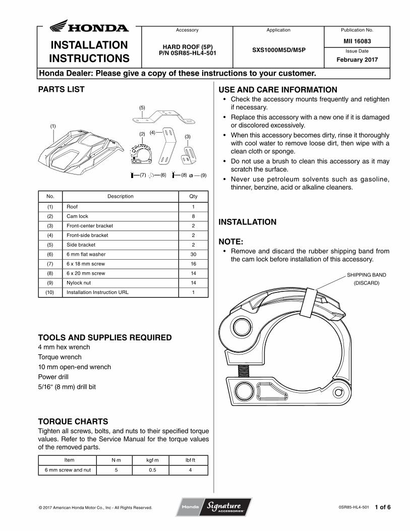
Issue Date INSTALLATION INSTRUCTIONS Publication No. Honda Dealer: Please give a copy of these instructions to your customer. © 2017 American Honda Motor Co., Inc - All Rights Reserved. 0SR85-HL4-501 1 of 6 Application Accessory PARTS LIST (1) (5) (3) (4) (9) ) No. Description Qty (1) Roof 1 (2) Cam lock 8 (3) Front-center bracket 2 (4) Front-side bracket 2 (5) Side bracket 2 (6) 6 mm flat washer 30 (7) 6 x 18 mm screw 16 (8) 6 x 20 mm screw 14 (9) Nylock nut 14 (10) Installation Instruction URL 1 TOOLS AND SUPPLIES REQUIRED 4 mm hex wrench Torque wrench 10 mm open-end wrench Power drill 5/16" (8 mm) drill bit TORQUE CHARTS Tighten all screws, bolts, and nuts to their specified torque values. Refer to the Service Manual for the torque values of the removed parts. Item N⋅m kgf⋅m lbf⋅ft 6 mm screw and nut 5 0.5 4 HARD ROOF (5P) P/N 0SR85-HL4-501 SXS1000M5D/M5P MII 16083 February 2017 USE AND CARE INFORMATION • Check the accessory mounts frequently and retighten if necessary. • Replace this accessory with a new one if it is damaged or discolored excessively. • When this accessory becomes dirty, rinse it thoroughly with cool water to remove loose dirt, then wipe with a clean cloth or sponge. • Do not use a brush to clean this accessory as it may scratch the surface. • Never use petroleum solvents such as gasoline, thinner, benzine, acid or alkaline cleaners. INSTALLATION NOTE: • Remove and discard the rubber shipping band from the cam lock before installation of this accessory. SHIPPING BAND (DISCARD)
Transcript of Publication No. INSTALLATION - Hondapowersports.honda.com/documentum/MW01/0SR85-HL4-501.pdf · Item...
Issue DateINSTALLATIONINSTRUCTIONS
Publication No.
Honda Dealer: Please give a copy of these instructions to your customer.
© 2017 American Honda Motor Co., Inc - All Rights Reserved. 0SR85-HL4-501 1 of 6
ApplicationAccessory
PARTS LIST
(1)
(5)
(3)(4)
(9)
)
No. Description Qty
(1) Roof 1
(2) Cam lock 8
(3) Front-center bracket 2
(4) Front-side bracket 2
(5) Side bracket 2
(6) 6 mm flat washer 30
(7) 6 x 18 mm screw 16
(8) 6 x 20 mm screw 14
(9) Nylock nut 14
(10) Installation Instruction URL 1
TOOLS AND SUPPLIES REQUIRED4 mm hex wrench
Torque wrench
10 mm open-end wrench
Power drill
5/16" (8 mm) drill bit
TORQUE CHARTSTighten all screws, bolts, and nuts to their specified torque values. Refer to the Service Manual for the torque values of the removed parts.
Item N⋅m kgf⋅m lbf⋅ft
6 mm screw and nut 5 0.5 4
HARD ROOF (5P)P/N 0SR85-HL4-501 SXS1000M5D/M5P
MII 16083
February 2017
USE AND CARE INFORMATION• Check the accessory mounts frequently and retighten
if necessary.
• Replace this accessory with a new one if it is damaged or discolored excessively.
• When this accessory becomes dirty, rinse it thoroughly with cool water to remove loose dirt, then wipe with a clean cloth or sponge.
• Do not use a brush to clean this accessory as it may scratch the surface.
• Never use petroleum solvents such as gasoline, thinner, benzine, acid or alkaline cleaners.
INSTALLATION
NOTE:• Remove and discard the rubber shipping band from
the cam lock before installation of this accessory.
SHIPPING BAND
(DISCARD)
© 2017 American Honda Motor Co., Inc - All Rights Reserved.2 of 6 0SR85-HL4-501
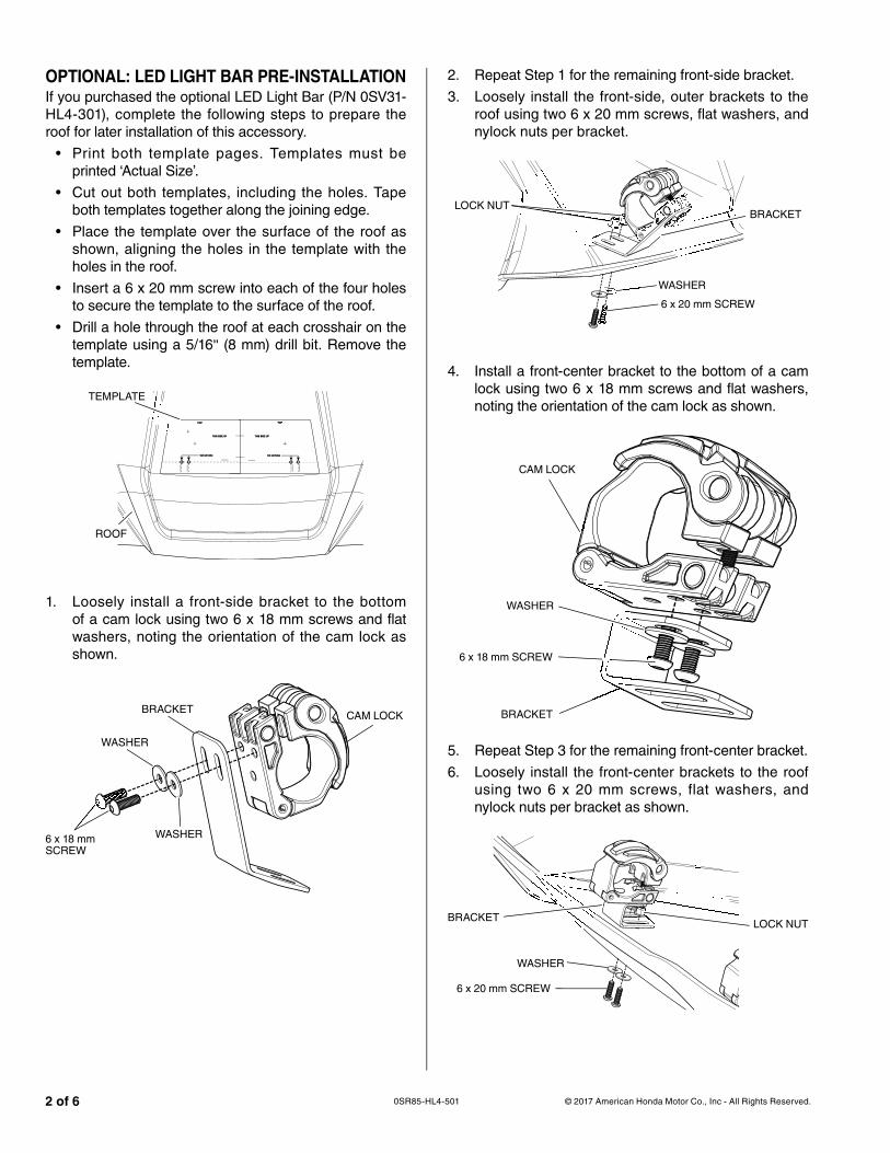
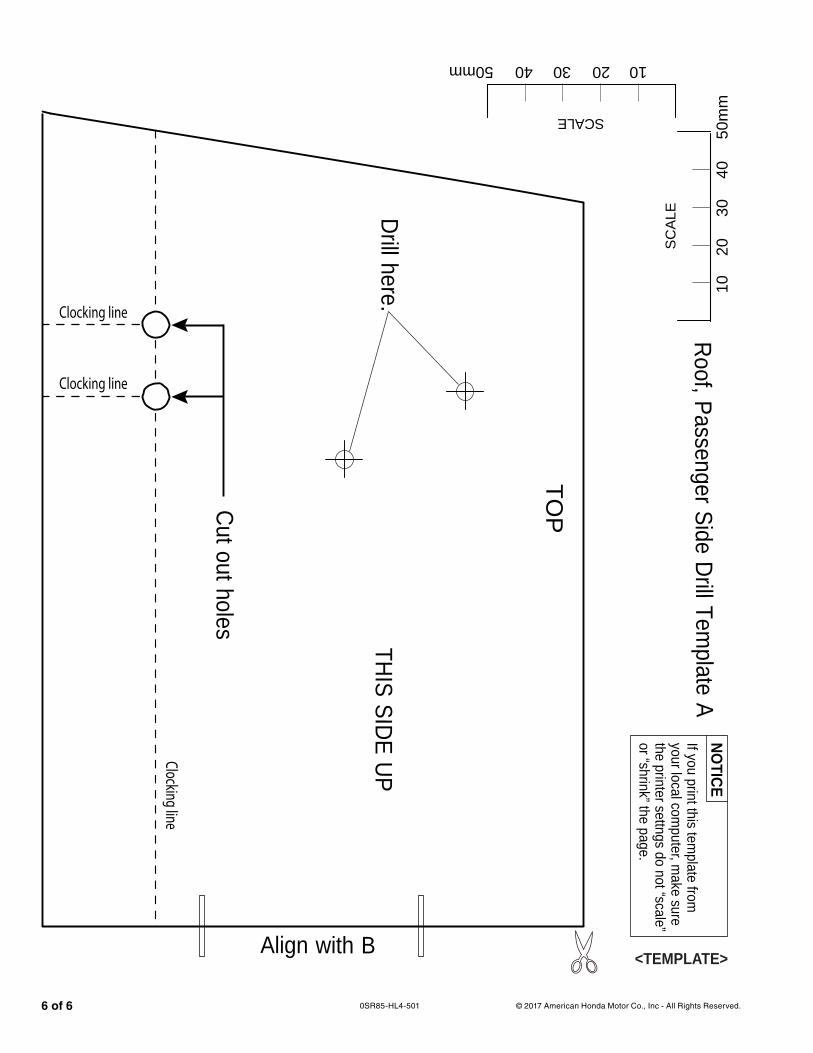
OPTIONAL: LED LIGHT BAR PRE-INSTALLATIONIf you purchased the optional LED Light Bar (P/N 0SV31-HL4-301), complete the following steps to prepare the roof for later installation of this accessory.
• Print both template pages. Templates must be printed ‘Actual Size’.
• Cut out both templates, including the holes. Tape both templates together along the joining edge.
• Place the template over the surface of the roof as shown, aligning the holes in the template with the holes in the roof.
• Insert a 6 x 20 mm screw into each of the four holes to secure the template to the surface of the roof.
• Drill a hole through the roof at each crosshair on the template using a 5/16" (8 mm) drill bit. Remove the template.
clocking line
clock
ing lin
e
clock
ing lin
e
Cut out holesCut out holes
THIS SIDE UPTHIS SIDE UP
TOPTOP
clocking line
clocking line
clocking line
THIS SIDE UPTHIS SIDE UP
TOPTOP
Cut out holesCut out holes
TEMPLATE
ROOF
1. Loosely install a front-side bracket to the bottom of a cam lock using two 6 x 18 mm screws and flat washers, noting the orientation of the cam lock as shown.
BRACKET
6 x 18 mm SCREW
WASHER
WASHER
mm
CAM LOCK
2. Repeat Step 1 for the remaining front-side bracket.
3. Loosely install the front-side, outer brackets to the roof using two 6 x 20 mm screws, flat washers, and nylock nuts per bracket.
LOCK NUT
6 x 20 mm SCREW
WASHER
BRACKET
4. Install a front-center bracket to the bottom of a cam lock using two 6 x 18 mm screws and flat washers, noting the orientation of the cam lock as shown.
BRACKET
CAM LOCK
WASHER
6 x 18 mm SCREW
5. Repeat Step 3 for the remaining front-center bracket.
6. Loosely install the front-center brackets to the roof using two 6 x 20 mm screws, flat washers, and nylock nuts per bracket as shown.
BRACKET
6 x 20 mm SCREW
WASHER
LOCK NUT
© 2017 American Honda Motor Co., Inc - All Rights Reserved. 3 of 60SR85-HL4-501
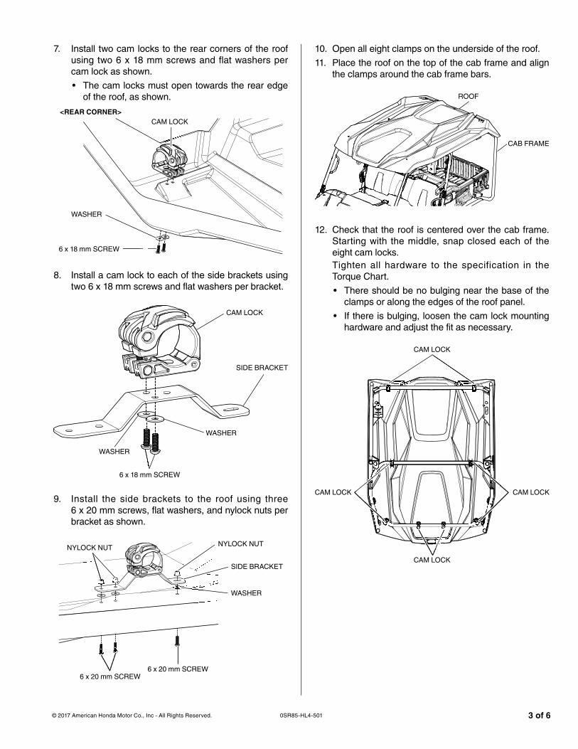
7. Install two cam locks to the rear corners of the roof using two 6 x 18 mm screws and flat washers per cam lock as shown.
• The cam locks must open towards the rear edge of the roof, as shown.
<REAR CORNER>CAM LOCK
6 x 18 mm SCREW
WASHER
8. Install a cam lock to each of the side brackets using two 6 x 18 mm screws and flat washers per bracket.
SIDE BRACKET
WASHER
WASHER
6 x 18 mm SCREW
CAM LOCK
9. Install the side brackets to the roof using three 6 x 20 mm screws, flat washers, and nylock nuts per bracket as shown.
SIDE BRACKET
WASHER
6 x 20 mm SCREW6 x 20 mm SCREW
NYLOCK NUT NYLOCK NUT
10. Open all eight clamps on the underside of the roof.
11. Place the roof on the top of the cab frame and align the clamps around the cab frame bars.
CAB FRAME
ROOF
12. Check that the roof is centered over the cab frame. Starting with the middle, snap closed each of the eight cam locks.Tighten all hardware to the specification in the Torque Chart.
• There should be no bulging near the base of the clamps or along the edges of the roof panel.
• If there is bulging, loosen the cam lock mounting hardware and adjust the fit as necessary.
CAM LOCK
CAM LOCK
CAM LOCKCAM LOCK
© 2017 American Honda Motor Co., Inc - All Rights Reserved.4 of 6 0SR85-HL4-501
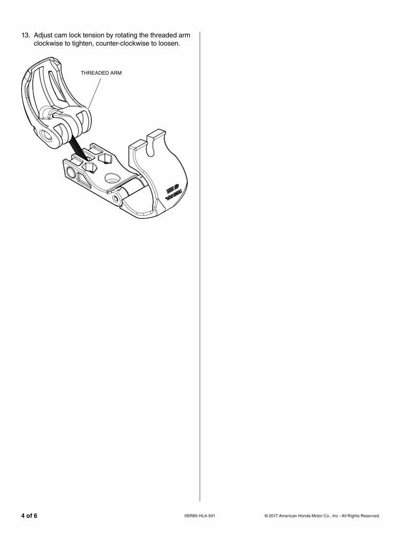
13. Adjust cam lock tension by rotating the threaded arm clockwise to tighten, counter-clockwise to loosen.
THREADED ARM
© 2017 American Honda Motor Co., Inc - All Rights Reserved. 5 of 60SR85-HL4-501
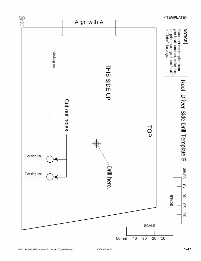
Roof, Driver Side Drill Template B
50m
m40
3020
10
SC
ALE
50mm 40 30 20 10
SCALE
If you print this template from
your local computer, m
ake surethe printer settngs do not “scale”or “shrink” the page.
NOTICE
<TEMPLATE>
Clocking line
Clocking line
Clocking line
THIS SIDE UP
TOP
Align with A
Cut out holes
Drill here.
© 2017 American Honda Motor Co., Inc - All Rights Reserved.6 of 6 0SR85-HL4-501
Roof, Passenger Side Drill Template A
50m
m40
3020
10
SC
ALE
50mm 40 30 20 10
SCALE
If you print this template from
your local computer, m
ake surethe printer settngs do not “scale”or “shrink” the page.
NOTICE
<TEMPLATE>
Clocking line
Clocking line
Clocking line
Cut out holes
Align with B
THIS SIDE UP
TOP
Drill here.