Publication Booklet - 130215.pdf
56
Reproduced with permission from springer Page 1 of 56 Scientifc Resources www.perfinthealthcare.co m March-2015 m
-
Upload
erik-chavez -
Category
Documents
-
view
224 -
download
0
Transcript of Publication Booklet - 130215.pdf

8/17/2019 Publication Booklet - 130215.pdf
http://slidepdf.com/reader/full/publication-booklet-130215pdf 1/56
Reproduced with permission from springer Page 1 of 56
ScientifcResources
www.perfinthealthcare.com
March-2015
m
8/17/2019 Publication Booklet - 130215.pdf
http://slidepdf.com/reader/full/publication-booklet-130215pdf 2/56
Page 2 of 56
26
14
Clinical Publication - 1
Clinical Publication - 2
Clinical Publication - 3
Clinical Publication - 4
Emmanuel C Mbalisike Tomas J.Vogi Stefan Zangos Katrin Elchier
Prakash Balakrishnan Jijo Paul
Basri Johan Jeet Abdullah Chai Hong Yeong Khean Lee Goh Boom Koon Yoong Gwo Fuang Ho
Carolyn Chue Wal Yim Anjali Kulkarni
Basri Johan Jeet Abdullah Chai Hong Yeong Khean Lee Goh Boom Koon Yoong Gwo Fuang Ho
Carolyn Chue Wal Yim Anjali Kulkarni
Michele Anzidei Renato Argiro Andrea Porfiri Fabrizio Boni Marco Anile Fulvio Zaccagna
Domenio Vitolo Luca Saba et al
Image-guided microwave thermoablation of hepatic tumours
using novel robotic guidence: an early experience
Robotic-assited thermal ablation of liver tumours
Robot-assited radiofrequency ablation of primary
and secondary liver tumours: early experience
Preliminary clinical experience with a dedicated
interventional robotic system for C-guided biopsies of lung
lesions: a comparison with the conventional manual technique
5
33

8/17/2019 Publication Booklet - 130215.pdf
http://slidepdf.com/reader/full/publication-booklet-130215pdf 3/56
Page 3 of 56
49
48
40 Clinical Publication - 5
Clinical Publication - 6
Clinical Publication - 7
Yilun Koethe Sheng Xu Gnanasekar Velusamy Brand J.Wood Aradhana M.Venkatesan
CM Chu* SCH Yu
From International Cancer Imaging Society(ICIS) 14th Annual eaching Course
Heidelberg. Germany 9-11 October 2014
Amarnath Chellathurai Saneej Kanhirat Kabilan Chokkappan Tiruchendur S Swaminanthan,
Nadhamuni Kulasekaran
Barnard Institue of Radiology, Madras Medical College, Government General Hospital,
Chennai-600033, India
Accurancy and efficacy of percutaneous biopsy and ablation
using robotic assistance under computed tomography guidance: a phantom study
Robot-assited navigation system for C-guided
percutaneous lung tumor procedures: our initial
experience in Hong Kong
echnical note : C-guided biopsy of
lung masses using an automated guiding
apparatus

8/17/2019 Publication Booklet - 130215.pdf
http://slidepdf.com/reader/full/publication-booklet-130215pdf 4/56
Page 4 of 56
50 Clinical Publication - 8
Clinical Publication - 9
Clinical Publication - 10
F. Cornells H. akaki M. Lakshmanan J.C. Durack J.P. Erinjeri G.I.Getrajdman M. Maybody
C.. Sofocleous S.B. Solomon G. Srimathveeravalli.
Boris Sehulz, M.D. Katrin Eichler, M.D. Firas Al-Butmeh, M.D. Claudia Frellesen, M.D. Tomas Vogl, M.D. Christoph Czerny, M.D. Stephan Zangos, M.D.
Robot assisted percutaneous placement of K-wires during minimal invasive
spinal interventions
Christoph Czemy 1 Katrin Eicher2 Boris Schulz2 Chirstof Schomerus3 Tomas J.Vogl2
Ingo Marzi and Stephan Zangos
Computed omography guided percutaneous
liver biospy using a robotic assistance device
corpse study.
Department of Diagnostic and Interventional Radiology, University Hospital Frankfurt,
Goethe-University,Frankfurt am Main,Germany
Comparison of C Fluoroscopy-Guided Manual and C-Guided
Robotic Positioning System for In Vivo Needle Placementsin Swine Liver
52
53

8/17/2019 Publication Booklet - 130215.pdf
http://slidepdf.com/reader/full/publication-booklet-130215pdf 5/56
Reproduced with permission from springer Page 5 of 56
INTERVENTIONAL
Image-guided microwave thermoablation of hepatic tumoursusing novel robotic guidance: an early experience
Emmanuel C. Mbalisike & Thomas J. Vogl &
Stefan Zangos & Katrin Eichler & Prakash Balakrishnan &
Jijo Paul
Received: 31 March 2014 /Revised: 8 July 2014 /Accepted: 13 August 2014# European Society of Radiology 2014
AbstractObjective To evaluate and compare novel robotic guidance
and manual approaches based on procedural accuracy, proce-
dural time, procedural performance, image quality as well as
patient dose during image-guided microwave thermoablation.
Method The study was prospectively performed between
June 2013 and December 2013 using 70 patients. Forty ran-
domly selected patients (group 1) were treated with manual
guidance and 30 patients (group 2) were treated using a novel
robotic guidance. Parameters evaluated were procedural ac-
curacy, total procedural time, procedural performance,
quantitative/qualitative image quality and patient dose. Two-
sided Student ’s t test and Wilcoxon rank-sum test were used totest the significance of the data and p values less than 0.05
were considered statistically significant.
Result Accuracy parameters were significantly higher ingroup 2 (all p <0.05). Total procedural time showed a mean
time difference of 3 min (group 2>group 1; p=0.0008).
Volume CT dose index and dose – length product were signif-
icantly lower for group 2 compared to group 1 (all p<0.05) for
CT fluoroscopy imaging. Total procedural performance score
was higher for group 2 compared to group 1 ( p=0.0001).
Image quality parameters were insignificant between exam-
ined groups.
Conclusion The novel robotic guided approach improved the
accuracy of targeting the target tumour, reduced patient dose
and increased procedural performance (which influences the
procedural safety) during ablation. Key Points
• Few reports are available in the literature regarding robotic-
assisted liver microwave ablation.
• The robotic guided approach improved accuracy of localiz-
ing the target tumour .
• Radiation dose on patients was reduced with the robotic
guidance.
• Numbers of insertions and readjustments were reduced ,
lowering chances of complications.
Keywords Microwave thermoablation . Robotic guided
approach . Procedural accuracy . Hepatic tumours . Patient
dose
Introduction
Microwave thermoablation therapy is heating to denature the
protein content of ablated solid tumour and surrounding soft
tissue. The therapy can either be curative or palliative for
patients with inoperable tumours and/or for dangerous surgi-
cal procedures; furthermore, it could also be a neoadjuvant
option to systemic chemotherapy in cases of hepatic/
E. C. Mbalisike (*)
Institute for Diagnostic and Interventional Radiology, K linikum Bad
Salzungen, Lindigalle 3, 36433 Bad Salzungen, Germany
e-mail: [email protected]
T. J. Vogl : S. Zangos : K. Eichler : J. Paul
Institute for Diagnostic and Interventional Radiology, Johann
Wolfgang Goethe University Hospital, Theodor-Stern-Kai 7,
60590 Frankfurt, Germany
T. J. Vogl
e-mail: [email protected]
S. Zangos
e-mail: [email protected]
K. Eichler
e-mail: [email protected]
J. Paul
e-mail: [email protected]
P. Balakrishnan
Perfint Healthcare Pvt. Ltd. (HO), No. 16, Southwest Boag Road,
T. Nagar, Chennai 600017, TN, India
e-mail: [email protected]
Eur Radiol
DOI 10.1007/s00330-014-3398-0
Clinical Publication - 1
This is for information and educational purpose only
8/17/2019 Publication Booklet - 130215.pdf
http://slidepdf.com/reader/full/publication-booklet-130215pdf 6/56
Reproduced with permission from springer Page 6 of 56
extrahepatic infiltration [1, 2]. It is a minimally invasive
treatment option which could also be relatively cumbersome
for both patients and interventional radiologist. Therapy re-
quires insertion of a microwave applicator into the hepatic
tumour; moreover, several trials of insertion may be required
to accurately localize the target tumour. This is usually thecase with tumours less than or equal to 3 cm in diameter [3, 4].
Multiple trials of insertion, depth, location and size of the
hepatic tumour would affect procedural safety for the patient
as well as treatment outcome at the end of the procedure,
which could lead to several complications, such as bleeding
around the puncture region [5, 6].
The increase in patient dose is dependent on the number of
CT examinations performed to localize the target tumour [7];
furthermore, in manual CT-guided microwave ablation thera-
py procedure, a relatively high radiation exposure to both
patient and procedural personnel is expected [7, 8]. Increasing
needle depth, insertion and number of needle repositionings
into a target tumour during an ablation procedure increases the
probability of developing complications that could be
life-threatening [5]. The introduction of the robotic
guidance system in surgical/interventional settings for
procedural planning, holding and moving instruments
precisely to allow better precision as well as accuracy
has been reported [9, 10]. The use of a robotic system
for image-guided real-time planning and intraprocedural
guidance during microwave thermoablation is still in its
pilot stages. This study was formulated with the aim to
assess and compare a novel robotic guidance with a
traditional manual approach during hepatic microwave
thermal ablation therapy procedure. In addition we eval-
uated procedural accuracy, procedural time, procedural
performan ce, ima ge qua lit y and patien t dose during
microwave therapy.
Materials and method
This study was prospectively performed between June 2013
and December 2013. Institutional review board approval and
informed consent were obtained.
Patient demography and assessment
A total of 70 patients underwent CT-guided microwave
thermoablation therapy of various hepatic tumours in 70 ses-
sions (one tumour/session) and the treated liver tumours were
of heterogeneous origin (primary and secondary; Table 1). Out
of 70 randomly selected patients, 40 patients (60±10 (46 – 82);
male, 25; female, 15) were treated by the manual approach
(group 1) and 30 (57.7±15 (33 – 83); male, 19, female, 11)
were treated using novel robotic system (MAXIO, Perfint
Healthcare, India; group 2) guidance.
O n l y p a t i e n t s w h o r e c e i v e d t r a n s a rt e r i a l
chemoembolization therapy (TACE) within 3 months prior
to thermoablation sessions were included in this study. During
CT-guided thermoablation, the presence of Lipiodol (deposit-
ed during TACE) helped to properly visualize and delineate
the target tumour [11]. Further patients included on the basis
of the aforementioned criteria were those with surgically
unresectable liver tumours, poor candidates for surgery due
to accompanying previous medical history, patients who
underwent previous multiple surgeries for recurrent metasta-
ses, those with at most five tumours and no greater than about
5 cm in maximal axial tumour diameter. Patients excluded
were as follows: those with uncontrolled primary malignancy,
wide diffused metastatic spread, more than five tumours/pa-
tient, tumours larger than 5 cm in maximal axial tumour
diameter, radiological evidence of lymph node metastases,
uncorrectable coagulopathy (international normalized ratio
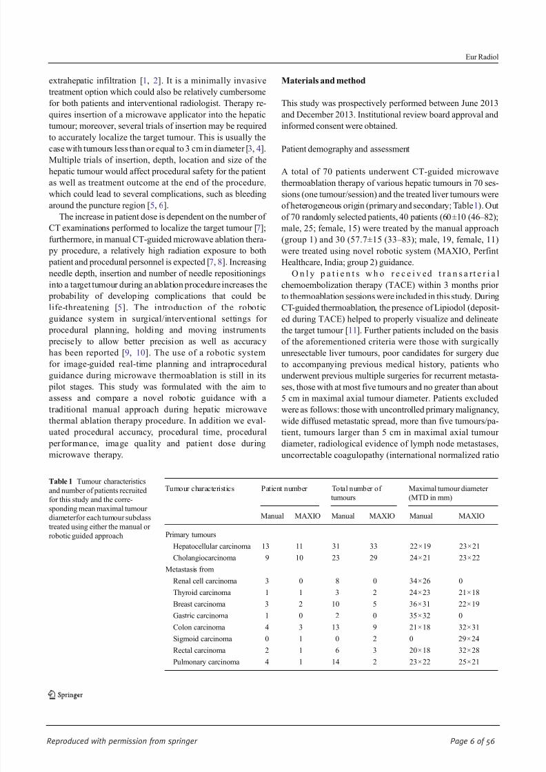
Table 1 Tumour characteristics
and number of patients recruited
for this study and the corre-
sponding mean maximal tumour
diameterfor each tumour subclass
treated using either the manual or
robotic guided approach
Tumour characteristics Patient number Total number of
tumours
Maximal tumour diameter
(MTD in mm)
Manual MAXIO Manual MAXIO Manual MAXIO
Primary tumours
Hepatocellular carcinoma 13 11 31 33 22×19 23×21
Cholangiocarcinoma 9 10 23 29 24×21 23×22
Metastasis from
Renal cell carcinoma 3 0 8 0 34×26 0
Thyroid carcinoma 1 1 3 2 24×23 21×18
Breast carcinoma 3 2 10 5 36×31 22×19
Gastric carcinoma 1 0 2 0 35×32 0
Colon carcinoma 4 3 13 9 21×18 32×31
Sigmoid carcinoma 0 1 0 2 0 29×24
Rectal carcinoma 2 1 6 3 20×18 32×28
Pulmonary carcinoma 4 1 14 2 23×22 25×21
Eur Radiol

8/17/2019 Publication Booklet - 130215.pdf
http://slidepdf.com/reader/full/publication-booklet-130215pdf 7/56
Reproduced with permission from springer Page 7 of 56
1.8 or platelet count 75,000), septicaemic patients and/or the
patients who refused thermal ablation. The treatment plan was
determined for all patients by the interventional radiologist in
conjunction with a multidisciplinary tumour board consisting
of health care staff members from surgical and medical on-
cology. No patient treated by either the group 1 or 2 approachrequired a long stay in hospital (more than 24 h).
Tumour localization
An initial unenhanced CT (Somatom Sensation 64; Siemens
Healthcare, Erlangen, Germany) imaging was performed for
all patients to identify the target region, tumour size and
anatomical location. This was followed by either a manual
or robotic guided procedure to localize the target tumour
(Fig. 1). Manual tumour localization was performed using
CT fluoroscopy for group 1 patients by placing two radi-
opaque copper metal wires over the region of interest
(Fig. 2). CT fluoroscopy is a sequence of CT imaging that
generates a single slice per CT exposure. Then a mark was
drawn on the patient ’s body using a marker pen to represent
the point of insertion of the microwave applicator. During the
group 2 procedure, patients were placed on an inflatable
mattress (SecureVac; Bionix radiation therapy, Toledo, Ohio)
secured to the CT table. This mattress was required to hold
and keep the patient in position to avoid or minimize move-
ment that would affect the positioning of the robotic guiding
system. Patient movement during CT examination or micro-
wave therapy was not significant enough to affect the therapy
procedure. The robotic system start-up was initialized before
docking was performed; this was followed by loading the
initially acquired unenhanced CT data into the system soft-
ware. Loaded data were then registered and reconstructed into
axial, coronal and sagittal planes which were then used for
plann ing. Tumour del ineat ion and seg mentati on were
performed in a 3D format to arrive at a virtual representation
of the proposed ablation volume (Figs. 3, 4a). This helps to
rule out possible areas of the patient ’s anatomy that could be
considered as “no go”, since injury to these structures could
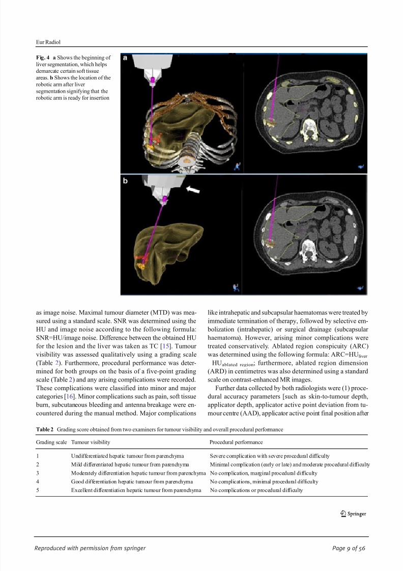
lead to treatment complication (Fig. 4a ). Planning is achieved
by setting the entry point on the skin’s surface and the target point inside the tumour. During planning, “no go” regions
were regarded as regions close to a major anatomical
structure/organ or close to the liver capsule for peripheral
lesions. These aforementioned regions could then be excluded
from the virtual ablation volume using the software built for
that purpose. While planning, system software provides the
required needle length, needle entry point and possible abla-
tion volume (based on manufacturer information for user,
IFU) for each selected applicator (Fig. 4b). These system-
planned parameters were then confirmed by the radiologist;
on the basis of this confirmation, the robotic arm automatical-
ly moves to the prescribed position over the patient ’s anatomy.
Thermoablation procedure
All microwave thermoablation therapies were performed in
aseptic conditions by two interventional radiologists with
more than 5 and 15 years of experience in abdominal inter-
vention, respectively. A mixture of sedative and analgesic
medication with fentanyl citrate (1 mg per kilogram of body
weight) and midazolam hydrochloride (0.010 – 0.035 mg/kg)
was titrated by the interventional radiologist until the patient
could tolerate the ablation procedure. Microwave applicators
used were either one of the following: Covidien (Covidien
Deutschland GmbH; applicator length, 12, 17 or 22 cm; emit-
ting portion, 3.7 cm), Amica (Hospital Services SpA, Aprilia,
Italy) applicator length, 15 or 20 cm; emitting portion, 2 cm
and Microsulis (Angiodynamics Inc, Amsterdam, the Nether-
lands; applicator length, 14 or 19 cm; emitting portion,
1.4 cm). Ablation time was controlled using the appropriate
software timer for all procedures. During the ablation proce-
dure, the applicator was advanced into the target tumour in a
pre-planned manner to achieve optimal overlapping ablation
zones. Then treatment was performed using appropriate mi-
crowave energy based on the radiologist ’s decision. At the end
of every session, applicator track coagulation was performed
to induce haemostasis and prevent malignant cells seeding in
the applicator track. The number of insertions (NOI) per-
formed with the applicator after each thermoablation proce-
dure for each patient was also noted. The same day after
thermoablation (within 24 h), a post-ablation unenhanced/
contrast-enhanced T1- and T2-weighted magnetic resonance
(MR) imaging was performed using a 1.5-Tesla Magnetom
Symphony (Siemens, Erlangen, Germany). Magnevist
(Schering, Berlin, Germany; 0.1 mmol/kg body weight of
gadopentetate dimeglumine) contrast material was used for
imaging for all patients (Fig. 2c).Fig. 1 Workflow chart for both manual and robotic guided approaches
Eur Radiol

8/17/2019 Publication Booklet - 130215.pdf
http://slidepdf.com/reader/full/publication-booklet-130215pdf 8/56
Reproduced with permission from springer Page 8 of 56
Image and data analysis
Two independent radiologists with more than 12 years of
experience in abdominal imaging quantitatively and qualita-
tively evaluated the post-microwave ablation image data sets.
The image data sets were viewed on GEPACS (General Elec-
tric Picture Archiving Communication System, GE
Healthcare, Dornstadt, Germany). Quantitative image quality
parameters such as Hounsfield unit (HU), image noise, signal-
to-noise ratio (SNR) [12 – 14] and tumour conspicuity (TC)
were assessed. Attenuation values were measured at the liver
parenchyma and at the tumour by the aid of a circular tool
(ROI). The ROI was measured on the axial slices and standard
deviation from the mean CT density within the ROI was taken
Fig. 2 Axial CT images during manual guided approach used for patients
in this study. Notice the two white points (long white arrow) signifying
the radio-opaque copper wires which were placed on the patient ’s surface
in a and used to localize the target tumour. The target tumour was easily
visible in theunenhanced CTimages owing to thepresence of Lipiodolas
is represented in thefigure. b Location of the inserted microwave ablation
applicator (the applicator active point was located outside the tumour
centre and was readjusted to increase the accuracy of insertion). c Post
ablation (within 24 h) MR T1-weighted contrast enhanced images of the
same patient. Notice the ablation region (long white arrow) which could
be easily differentiated from the l iver parenchyma
Fig. 3 Unenhanced CT images
used for planning during robotic
guided approach. a Shows the
delineated tumour (long arrow)
and the tumour ( short arrow) in
liver segment 6. b Shows the
proposed point of entry from the
skin surface to the target tumour
signified by the purple line
Eur Radiol
8/17/2019 Publication Booklet - 130215.pdf
http://slidepdf.com/reader/full/publication-booklet-130215pdf 9/56
Reproduced with permission from springer Page 9 of 56
as image noise. Maximal tumour diameter (MTD) was mea-
sured using a standard scale. SNR was determined using the
HU and image noise according to the following formula:
SNR=HU/image noise. Difference between the obtained HU
for the lesion and the liver was taken as TC [15]. Tumour
visibility was assessed qualitatively using a grading scale
(Table 2). Furthermore, procedural performance was deter-
mined for both groups on the basis of a five-point grading
scale (Table 2) and any arising complications were recorded.
These complications were classified into minor and major
categories [16]. Minor complications such as pain, soft tissue
burn, subcutaneous bleeding and antenna breakage were en-
countered during the manual method. Major complications
like intrahepatic and subcapsular haematomas were treated by
immediate termination of therapy, followed by selective em-
bolization (intrahepatic) or surgical drainage (subcapsular
haematoma). However, arising minor complications were
treated conservatively. Ablated region conspicuity (ARC)
was determined using the following formula: ARC=HU liver
−HUablated region; furthermore, ablated region dimension
(ARD) in centimetres was also determined using a standard
scale on contrast-enhanced MR images.
Further data collected by both radiologists were (1) proce-
dural accuracy parameters [such as skin-to-tumour depth,
applicator depth, applicator active point deviation from tu-
mour centre (AAD), applicator active point final position after
Fig. 4 a Shows the beginning of
liver segmentation, which helps
demarcate certain soft tissue
areas. b Shows the location of the
robotic arm after liver
segmentation signifying that the
robotic arm is ready for insertion
Table 2 Grading score obtained from two examiners for tumour visibility and overall procedural performance
Grading scale Tumour visibility Procedural performance
1 Undifferentiated hepatic tumour from parenchyma Severe complication with severe procedural difficulty
2 Mild differentiated hepatic tumour from parenchyma Minimal complication (early or late) and moderate procedural difficulty
3 Moderately differentiation hepatic tumour from parenchyma No complication, marginal procedural difficulty
4 Good differentiation hepatic tumour from parenchyma No complications, minimal procedural difficulty
5 Excellent differentiation hepatic tumour from parenchyma No complications or procedural difficulty
Eur Radiol

8/17/2019 Publication Booklet - 130215.pdf
http://slidepdf.com/reader/full/publication-booklet-130215pdf 10/56
Reproduced with permission from springer Page 10 of 56
readjustment (AAFP) and number of readjustments] and (2)
total procedure time [including planning time, preparation
time (insertion time and ablation time)]. An explanation of
the assessed parameters is given in Table 3.
We collected radiation dose parameters such as CTDIvol
and dose – length product (DLP) from the system-generated patient protocol [17, 18]. An appropriate k factor (0.015 mSv/
(mGy cm)) for the abdomen was used to convert DLP to
effective dose (ED; mSv). We also noted the tube potential
(kV) and the tube current – time product (mAs).
Statistical analysis
BiAS 9.02 (Epsilon Verlag, Darmstadt, Germany) statistical
software was used to perform the statistical analyses for this
study and a p value of 0.05 was considered to be statistically
significant. Continuous variables such as patient age, MTD,
skin-to-tumour depth, applicator depth, AAD, AAFP, number
of readjustments, planning time, preparation time, insertion
time, ablation time, HU, image noise, SNR, TC, ARC, DLP
and CTDIvol were are reported as mean±standard deviation
and range. Quantitative parameters (HU, image noise, SNR,
TC, ARC, DLP, CTDIvol) were tested between the two
groups using the two-sided Student ’s t test. Wilcoxon’s rank-
sum test was used to examine the accuracy of the procedure,
total procedural time, procedure performance and qualitative
tumour visibility between the two groups.
Results
Procedural accuracy
Mean number of needle insertions per procedure was signif-
icantly ( p=0.0001) lower (48.7 %) in group 2 (2.1±0.73) in
comparison with group 1 (4.1±1.8; Fig. 2b). Mean AAD and
AAFP were significantly ( p=0.0002; p=0.0001) lower in
group 2 (5.3±1.8; 1.9±1.7) in comparison with group 1
(11.1±2.2; 6.2±1.7). Mean number of readjustments was
significantly lower ( p=0.0001) for group 2 (1.13±0.7) com-
pared to group 1 (3± 1.8; Table 4). The measured skin-to-
tumour depth and applicator depth were not statistically sig-
nificant between groups ( p=0.7498, p=0.3135).
Tumour size, visibility and conspicuity
With regards to MTD of the hepatic tumours, no statistically
significant difference was obtained between the two groups
( P >0.05; Table 4). The obtained SNR values measured for
both the liver and tumour were not significantly different
between the two groups ( p=0.7858, p=0.2901; Table 5).
The calculated TC values showed insignificant results ( p=
0.1626; Table 5) during comparison between groups. Quali-
tative values of tumour visibility obtained between groups
showed no statistical significance ( p=0.1785). Obtained
ARC showed no statistical significance between groups; fur-
thermore, ARD was also determined (Table 5).
Procedural duration
Mean insertion time was significantly lower ( p=0.0001) for
group 2 (1.5±0.57) compared to group 1 (2.9±1.3); whereas,
mean planning time and preparation time were lower for
group 1 (6.8±2.8, 3.8±0.75) than in group 2 (9.7±1.3, 5.4±
0.8; Table 4). Mean ablation time was not significantly differ-
ent between groups 1 and 2 ( p=0.7751). Mean total proce-
dural time was slightly higher ( p=0.0008) for group 2 (25.2±
2.8 min) compared to group 1 (22.15±3.95 min).
Radiation dose parameters
For the CT fluoroscopy image data acquisition, CTDIvol and
DLP were significantly lower for group 2 compared to group 1
( p=0.006; p=0.003; Table 6). CTDIvol and DLP between both
groups showed non-significant difference for the initial
unenhanced imaging ( p=0.4935; p=0.0521). The acquired
number of slices during unenhanced imaging was constant for
both groups; furthermore, CT fluoroscopy showed statistically
lower dose values ( p=0.0001) for group 2 compared to group 1.
Table 3 Definitions of the assessed parameters
Skin-to-tumour depth Distance from the skin surface to the centre of the tumour
Applicator depth Initial length of the applicator measured from the target tumour to the body surface
Applicator active point deviation (AAD) Distance of the applicator active point to the centre of the target tumour
Applicator active point final position (AAFP) Distance of the applicator active point to the centre of the target tumour after final readjustment
Number of readjustments Number of times the applicator was readjusted to better target the tumour centre
Planning time Time duration to plan either the group 1 or 2 approaches
Preparation t ime Time duration from the end of planning to the beginning of applicator insertion
Insertion time Time duration for an accurate insertion of the applicator into the target tumour
Ablation time Duration of the microwave thermoablation therapy
Eur Radiol
8/17/2019 Publication Booklet - 130215.pdf
http://slidepdf.com/reader/full/publication-booklet-130215pdf 11/56
Reproduced with permission from springer Page 11 of 56
The calculated ED to the patient for the complete procedure
was lower (6.7 %) in group 2 compared to group 1 (Table 6).
Procedural performance
Procedural performance was better in group 2 (4.3±0.58) than
in group 1 (3.27±0.93) and showed statistically significant
difference ( p=0.0001). There were four complications report-
ed during thermoablation for group 1 (Tables 2, 4, 7); howev-
er, complications were completely absent with the group 2
treatment approach.
Discussion
The present study highlights the performance of a novel
robotic guidance during microwave thermoablation in
comparison to the manual approach. The robotic guided ap-
proach helps to reduce the number of applicator insertions
(which reduces the probability of complications arising),
shorten the insertion times, decrease the number of applicator
readjustments (improve the accuracy of the puncture) and
increase performance during the microwave thermoablation
procedure.
There were two minor and two major complications report-
ed in group 1; however, no complications developed in
group 2. It was reported that increased needle depth and
insertion into the target organ during an ablation procedure
could increase the chances of developing complications rang-
ing from mild to life-threatening haemorrhages [5]. The four
reported complications could have developed as a result of
multiple trials of applicator insertions into the ablation site;
moreover, the robotic approach provided no complications
owing to significantly reduced applicator NOI and
readjustments.
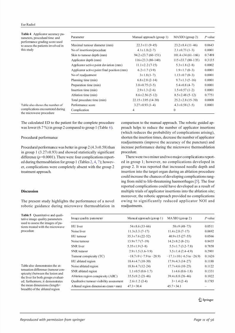
Table 4 Applicator accuracy pa-
rameters, procedural time and
performance grading score used
to assess the patients involved in
this study
Table also shows the number of
complications encountered during
the microwave procedure
Parameter Manual approach (group 1) MAXIO (group 2) P value
Maximal tumour diameter (mm) 22.3 ±11 (9 – 45) 23.2±8.4 (11 – 46) 0.0643
No of insertions/procedure 4.1± 1.8 (2 – 7) 2.1±0.73 (1 – 3) 0.0001
Skin to tumour depth (mm) 94.2 ±23.7 (60 – 151) 101.4 ±34 (61 – 166) 0.7498
Applicator depth (mm) 116±23.3 (80 –
140) 115 ±33.7 (80 –
135) 0.3135
Applicator active point deviation (mm) 11.1±2.2 (7 – 15) 5.3±1.8 (2 – 8) 0.0002
Applicator active point final position (mm) 6.2±1.7 (3 – 9) 1.9±1.7 (0 – 3) 0.0001
No of readjustment 3± 1.8 (1 – 7) 1.13±0.7 (0 – 3) 0.0001
Planning time (min) 6.8±2.8 (2 – 14) 9.7±1.3 (5 – 16) 0.0001
Preparation time (min) 3.8±0.75 (3 – 5) 5.4±0.8 (4 – 7) 0.0001
Insertion time (min) 2.9±1.3 (2 – 6) 1.5±0.57 (1 – 2) 0.0001
Ablation time (min) 8.6±2.56 (5 – 12) 8.5±2.48 (5 – 12) 0.7751
Total procedure time (min) 22.15 ± 3.95 (14 – 30) 25.2±2.8 (15 – 30) 0.0008
Performance score 3.27±0.93 (1 – 4) 4.3±0.58 (3 – 5) 0.0001
Complication 4 0
Table 5 Quantitative and quali-
tative image quality parameters
used to assess the images of pa-
tients treated with the microwave
procedure
Table also demonstrates the at-
tenuation difference (tumour con-
spicuity) between the lesion and
the liver for both groups evaluat-
ed; furthermore, it demonstrates
the mean dimensions (length×
breadth) of the ablated region
Image quality parameter Manual approach (group 1) MAXIO (group 2) P value
HU liver 54±8.6 (33 – 66) 58±9 (48 – 73) 0.0511
Noise liver 11.3±3.3 (7 – 17) 11.4±2.8 (7 – 17) 0.0692
HU tumour 35.3±7.6 (22 – 52) 40.9±15 (27 – 55) 0.0566
Noise tumour 13.9± 7.7 (7 – 19) 14.2±8.2 (8 – 21) 0.8435
SNR liver 5.35±1.9 (3 – 8) 5.5±1.7 (3.2 – 7.8) 0.7858
SNR tumour 2.9±1.5 (1.6 – 3.9) 3.5±1.4 (2.4 – 4.9) 0.2901
Tumour conspicuity (TC) −18.7±9 (−7.9 to −28.9) −17.1±10 (−6.5 to −26.9) 0.1626
HU ablated region 18.4±4.7 (10 – 30) 17.9±4.3 (14 – 27) 0.1188
Noise ablated region 18.8± 4.7 (12 – 24) 17.7±4.6 (10 – 25) 0.1122
SNR ablated region 1.1±0.5 (0.6 – 1.7) 1±4.6 (0.6 – 1.8) 0.1331
Ablation region conspicuity (ARC) 35.5±9.2 (21 – 46) 39.4±8.8 (26 – 46) 0.1022
Qualitative tumour visibility assessment 2.6±1.2 (2 – 4) 3±1.4 (2 – 4) 0.1785
A blated region dimensions (mm ×mm) 47.3×30.4 45.7×34.1 –
Eur Radiol

8/17/2019 Publication Booklet - 130215.pdf
http://slidepdf.com/reader/full/publication-booklet-130215pdf 12/56
Reproduced with permission from springer Page 12 of 56
Certain number of readjustments was necessary to increase
the accuracy of the applicator placement at the centre of the
target tumour before microwave ablation. In the present study
we arrived at applicator deviations of 11.1 mm and 5.3 mm
respectively for group 1 and 2 approaches using patients
during our initial attempt. However, the applicator was
readjusted a few times to increase accuracy, which reduced
the applicator deviation to 6.2 mm and 1.9 mm respectively.
Previous studies on stable materials (phantoms and vertebra)
using robotic devices during fluoroscopic punctures arrived at
average needle tip deviations of 1.1 mm and 4.6 mm after
additional fine needle adjustments [19, 20]. It is of importance
to note that the two mentioned studies were performed on
stable structures in contrast to the present study, where the
patient ’s liver may have moved involuntarily. Furthermore,
obtained values were very close to those of the two previously
published studies.
Applicator insertion time (also NOI) was remarkably re-
duced for the robotic guidance approach compared to the
manual approach, as the robotic system was already posi-
tioned over the target region and clearly shows the puncture
location during applicator insertion. However, slight increases
in planning time and preparation time were seen in group 2
because of the additional time it takes for data registration,
software planning and movement of the robotic arm to the
target location. As a result of an increase in both planning and
preparation time, a slight but negligible increase in mean total
procedural time (3 min) was noticed during the robotic ap-
proach in comparison with group 1.
As regards to the procedure performance (Table 2), we
noticed that group 2 achieved higher scores than group 1. This
is due to reduced associated procedure complications and
procedural difficulty (owing to reduced insertion time and
improved accuracy of localizing the target tumour). Tumour
margins were delineated using real-time CT images, while
ablation regions were determined using ARC and ARD
values. As regards to tumour conspicuity, the attenuation
between the tumour and hepatic parenchyma showed good
difference in both groups, which aided the easy visual identi-
fication of the tumour. We further qualitatively analysed tu-
mour visibility, also allowing easy identification of the tu-
mours, aided procedural planning in both cases and confirma-
tion of the applicator in the tumour by the examiner.
Dose parameters such as CTDIvol and DLP were signifi-
cantly lower in the robotic guidance approach compared to the
manual approach during CT fluoroscopy imaging, which was
due to a reduced number of acquired slices. Calculated ED in
patients was decreased in the robotic guidance procedure com-
pared to the manual approach. This reduction was due to the
following reasons: reduced applicator NOI, reduced insertion
time and a reduced number of CT fluoroscopy imagings. This
confirms that using the robotic assisted CT-guided approach (as
in group 2) provides lower patient dose compared to the manual
approach (group 1) during the microwave ablation procedure.
A possible limitation associated with this study could be
the use of real-time CT imaging. Real-time ultrasound (US)
imaging has been used for image guidance purposes during
applicator placement since it eliminates patient dose, whereas
the robotic guided approach requires an initial CT or CT
images to be loaded from previous acquisitions. A further
limitation is the fact that this is an early experience; more
studies using more patients or multi-institutional studies to
explore the usefulness of the robotic system during
Table 6 Radiation dose parame-
ters and thetotaleffective dose for
both groups evaluated
Radiation dose parameters Manual approach (group 1) MAXIO (group 2) P value
Tube potential (kV) 120 120 –
Tube current time product (mAs) 130.9±43.9 (105 – 155) 132.5 ±30.5 (112 – 158) 0.8918
No of slices 42 42 –
CTDI vol (mGy) 7.6±3 (5 – 12) 8.1±1.6 (6 – 13) 0.4935
DLP (mGy cm) 190.9±93 (144 – 244) 193.8±93 (148 – 251) 0.0521
CT fluoro. Tube potential (kV) 120 120 –
Tube current – time product (mAs) 70 70 –
CT fluoro. no. of slices 34 ±10 (17 – 47) 22.2±7 (12 – 31) 0.0001
CTDIvol (mGy) 136.9±47 (94 – 175) 94.9±48.9 (51 – 121) 0.006
DLP (mGy cm) 70.2±23.6 (39 – 98) 49.2±19.5 (34 – 75) 0.003
Effective dose (mSv) 3.9 3.64 –
Table 7 Procedural performance level in relation to treated patients
based on grading scale explained in Table 2 during thermoablation
procedure
Grading scale Manual approach (group 1) MAXIO (group 2)
Grade 1 2 (5 %) 0 (0 %)
Grade 2 2 (5 %) 0 (0 %)
Grade 3 10 (25 %) 0 (0 %)
Grade 4 16 (40 %) 14 (46.6 %)
Grade 5 10 (25 %) 16 (53.3 %)
Mean and SD 8±6 6±7.4
Eur Radiol

8/17/2019 Publication Booklet - 130215.pdf
http://slidepdf.com/reader/full/publication-booklet-130215pdf 13/56
Reproduced with permission from springer Page 13 of 56
interventional procedures may be useful. Another limitation
was the time duration required for robotic guidance system
set-up, planning and localization. If this time duration could
be reduced, this would go a long way to improve procedure
duration. From our point of view, the problem of time duration
could be solved if the vendor reduces the number of stepsrequired for planning and localization.
In conclusion, we would like to state that the robotic guided
approach can shorten the number of applicator insertions, short-
en the insertion time, decrease the number of applicator
readjustments (which reduces the chances of complications
arising), increase the accuracy of puncturing and improve pro-
cedural performance (which increased procedure safety) during
treatment of hepatic tumours. A significant reduction of
CTDIvol and DLP during CT fluoroscopy data acquisition
was achieved, reducing patient dose. We would like to further
state that the guidance of microwave ablation punctures using
robotic guidance needs to be thoroughly investigated using more
patient groups so as to unlock the maximum potential of this
technique and achieve precise localization of the target tumour.
Acknowledgments We would like to thank Mrs. Neddermann and Mr.
Ackermann of Johann Wolfgang Goethe University Frankfurt, Germany
as well as Dr. Anjali of Perfint Healthcare for their relentless support and
efforts during the time of this study. The authors would also like to
acknowledge and thank Perfint Healthcare India for allowing the use of
their MAXIO robotic system during the duration of the study. The
scientific guarantor of this publication is Jijo Paul, Ph.D. The authors of
this manuscript declare relationships with the following companies:
Prakash Balakrishnan, M.Sc. is an employer of Perfint Healthcare Pvt.
Ltd. The authors would like to thank Perfint Healthcare for loaning us
their system for our study. The authors state that this work did not receive
any funding. No complex statistical methods were necessary for this
paper. Institutional review board approval was obtained. Written in-
formed consent was waived by the institutional review board. The study
has not been reported before anywhere. Methodology: prospective, per-
formed at one institution.
References
1. Knavel EM, Brace CL (2013) Tumor ablation: common modalities
and general practices. Tech Vasc Interv Radiol 16(4):192 – 200
2. Vogl TJ, Naguib NNN, Gruber-Rouh T, Koitka K, Lehnert T, Nour-
Eldin NE (2011) Microwave ablation therapy: clinical utility intreatment of pulmonary metastases. Radiology 261:643 – 651
3. Ma X, Arellano RS, Gervais DA, Hahn PF, Mueller PR, Sahani DV
(2010) Success of image-guided biopsy for small (<3 cm) focal liver
lesions in cirrhotic and non-cirrhotic individuals. J Vasc Interv Radiol
21:1539 – 1547
4. Yu SC, Liew CT, Lau WY, Leung TW, Metreweli C (2001) US-
guided percutaneous biopsy of small (<1-cm) hepatic lesions.
Radiology 218:195 – 199
5. Nour-Eldin NE,Naguib NN,Mack M, Abskharon JE, VoglTJ (2011)
Pulmonary hemorrhage complicating radiofrequency ablation, from
mild hemoptysis to life threatening pattern. Eur Radiol 21(1):197 –
204
6. Ding J, Jing X, Liu J et al (2013) Complications of thermal ablation
of hepatic tumours: comparison of radiofrequency and microwave
ablative techniques. Clin Radiol 68(6):608 –
6157. Kloeckner R, dos Santos DP, Schneider J, Kara L, Dueber C, Pitton
MB (2013) Radiation exposure in CT-guided interventions. Eur J
Radiol 82(12):2253 – 2257
8. Kato R, Katada K, Anno H, Suzuki S, Ida Y, Koga S (1996)
Radiation dosimetry at CT fluoroscopy: physician’s hand dose and
development of needle holders. Radiology 201:576 – 578
9. Solomon SB, Patriciu A, Bohlman ME, Kavoussi LR, Stoianovici D
(2002) Robotically driven interventions: a method of using CT
fluoroscopy without radiation exposure to the physician. Radiology
225:277 – 282
10. Shin TY, Choi KH, Lim SK et al (2013) Simplified zero ischemia in
robot assisted partial nephrectomy: initial yonsei experience. Kor J
Urol 54:78 – 84
11. Paul J, Vogl TJ, Mbalisike EC (2012) Radiation dose and image
quality evaluation relative to different contrast media using cone- beam CT. Imaging Med 4(5):505 – 513
12. Paul J, Bauer RW, Maentele W, Vogl TJ (2011) Image fusion
in dual energy computed tomography for detection of various
anatomic structures – effect on contrast enhancement, contrast-
to-noise ratio, signal-to-noise ratio and image quality. Eur J
Radiol 80(2):612 – 619
13. Paul J, Krauss B, Banckwitz R, Maentele W, Bauer RW, Vogl TJ
(2012) Relationships of clinical protocols and reconstruction kernels
with image quality and radiation dose in a 128-slice CT scanner:
study with an anthropomorphic and water phantom. Eur J Radiol
81(5):e699 – e703
14. Paul J, Jacobi V, Bazrafshan B, Farshid P, Vogl T (2013)
Effect of contrast material on radiation dose in an adult
cardiac dual-energy CT using retrospective ECG-gating.
Health Phys 105(2):156 – 16415. Koelblinger C, Schima W, Berger-Kulemann V et al (2013) C-arm
CT during hepatic arteriography tumour-to-liver contrast:
intraindividual comparison of three different contrast media applica-
tion protocols. Eur Radiol 23:938 – 942
16. Goldberg SN, Grassi CJ, Cardella JF et al (2005) Image-guided
tumor ablation: Standardization of terminology and reporting criteria.
Radiology 235:728 – 739
17. Paul J, Schell B, Kerl JM, Maentele W, Vogl TJ, Bauer RW (2011)
Effect of contrast material on image noise and radiation dose in adult
chest computed tomography using automatic exposure control: a
comparative study between 16-, 64-and 128-slice CT. Eur J Radiol
79(2):e128 – e132
18. Paul J, Mbalisike EC, Nour-Eldin NE, Vogl TJ (2013) Dual-
source 128-slice MDCT neck: radiation dose and image qual-
ity estimation of three different protocols. Eur J Radiol 82(5):787 – 796
19. Tam AL, Mohamed A, Pfister M et al (2010) C-arm cone beam
computed tomography needle path overlay for fluoroscopic guided
vertebroplasty. Spine 35:1095 – 1099
20. Schulz B, Eichler K, Siebenhandl P et al (2013) Accuracy and speed
of robotic assisted needle interventions using a modern cone beam
computed tomography intervention suite: a phantom study. Eur
Radiol 23:198 – 204
Eur Radiol

8/17/2019 Publication Booklet - 130215.pdf
http://slidepdf.com/reader/full/publication-booklet-130215pdf 14/56
Reproduced with permission from springer Page 14 of 56
INTERVENTIONAL
Robotic-assisted thermal ablation of liver tumours
Basri Johan Jeet Abdullah & Chai Hong Yeong &
Khean Lee Goh & Boon Koon Yoong & Gwo Fuang Ho &
Carolyn Chue Wai Yim & Anjali Kulkarni
Received: 9 April 2014 /Revised: 20 June 2014 /Accepted: 7 August 2014# European Society of Radiology 2014
Abstract
Objective This study aimed to assess the technical success,radiation dose, safety and performance level of liver thermal
ablation using a computed tomography (CT)-guided robotic
positioning system.
Methods Radiofrequency and microwave ablation of liver
tumours were performed on 20 patients (40 lesions) with the
assistance of a CT-guided robotic positioning system. The
accuracy of probe placement, number of readjustments and
total radiation dose to each patient were recorded. The perfor-
mance level was evaluated on a five-point scale (5 – 1: excel-
lent – poor). The radiation doses were compared against 30
patients with 48 lesions (control) treated without robotic
assistance.
Results Thermal ablation was successfully completed in 20
patients with 40 lesions and confirmed on multiphasiccontrast-enhanced CT. No procedure related complications
were noted in this study. The average number of needle
readjustment was 0.8±0.8. The total CT dose (DLP) for the
entire robotic assisted thermal ablation was 1382±
536 mGy.cm, while the CT fluoroscopic dose (DLP)
per lesion was 352 ± 228 mGy.cm. There was no statis-
tically significant ( p >0.05) dose reduction found be-
tween the robotic-assisted versus the conventional
method.
Conclusion This study revealed that robotic-assisted planning
and needle placement appears to be safe, with high accuracy
and a comparable radiation dose to patients. Key Points
• Clinical experience on liver thermal ablation using CT-
guided robotic system is reported.
• The technical success, radiation dose, safety and perfor-
mance level were assessed.
• Thermal ablations were successfully performed, with an
average performance score of 4.4/5.0.
• Robotic-assisted ablation can potentially increase capabili-
ties of less skilled interventional radiologists.
• Cost-effectiveness needs to be proven in further studies.
Keywords Robot . Radiofrequency ablation . Microwave
ablation . Liver tumour . CT-guided
Introduction
Image-guided thermal ablations such as radiofrequency abla-
tion (RFA) and microwave ablation have emerged as attractive
minimally invasive interventional treatments of liver malig-
nancies, as first-line therapy and in patients ineligible for
surgery. Probes are percutaneously inserted into the tumour
B. J. J. Abdullah : C. H. Yeong
Department of Biomedical Imaging and University of Malaya
Research Imaging Centre, Faculty of Medicine,
University of Malaya, 50603 Kuala Lumpur, Malaysia
B. J. J. Abdullah (*) : C. H. Yeong : K. L. Goh
Department of Internal Medicine, Faculty of Medicine,
University of Malaya, 50603 Kuala Lumpur, Malaysia
e-mail: [email protected]
B. K. YoongDepartment of Surgery, Faculty of Medicine, University of Malaya,
50603 Kuala Lumpur, Malaysia
G. F. Ho
Department of Oncology, Faculty of Medicine,
University of Malaya, 50603 Kuala Lumpur, Malaysia
C. C. W. Yim
Department of Anesthesia, Faculty of Medicine,
University of Malaya, 50603 Kuala Lumpur, Malaysia
A. Kulkarni
Perfint Healthcare Corporation, Florence, OR 97439, USA
Eur Radiol
DOI 10.1007/s00330-014-3391-7
Clinical Publication - 2Clinical Publication - 2

8/17/2019 Publication Booklet - 130215.pdf
http://slidepdf.com/reader/full/publication-booklet-130215pdf 15/56
Reproduced with permission from springer Page 15 of 56
and a volume of tissue is devitalized either by heat (using
radiofrequency or microwave) or freezing (cryoablation). Ac-
curate placement of the probe is critical to achieving not only
technical success (for lesions high in the dome or large lesions
requiring multiple overlapping ablations), but also vital in
ensuring adequate ablation margins to prevent local tumour recurrence [1]. Additionally, patient safety is compromised
with imprecise electrode placement, which may lead to major
complications such as pleural and gastrointestinal perfora-
tions, laceration of vessels with bleeding, or thermal collateral
damage with bile duct stenosis, biloma, gastrointestinal in-
flammation and subsequent perforation [2].
To improve trajectory planning and targeting, surgical nav-
igation systems have recently been adapted to the needs of
interventional radiology [3, 4]. The navigation systems (com-
monly known as “robots”) assist in either planning and plac-
ing of the needles/probes, or allow tracking the position of a
surgical tool that is projected in real-time in the patient ’s
corresponding computed tomography (CT) or magnetic reso-
nance (MR) images [5]. The aim of these CT or MR compat-
ible robots is to increase the accuracy of needle or probe
placement through three-dimensional (3D) imaging and com-
puterized trajectory planning in arbitrary orientated tracks, to
improve the outcomes of interventional therapies. Further-
more, in highly inaccessible lesions that require multiple plane
angulations, robotically assisted needle placement may im-
prove access to the target by allowing off-axial paths of needle
placement. Previous studies have confirmed high targeting
accuracy of a commercially available robot in phantom and
animal experiments [4], as well as in clinical settings [3, 5].
Reduction of exposure to radiation during CT fluoroscopy to
clinical staff and patient is another potential benefit [3]. Al-
though ultrasound-guidance provides a radiation-free environ-
ment and allows off-axial needle paths, it has several limita-
tions. These include ultrasound-occult lesions, difficulty in
visualizing deep lesions, shadowing artefacts caused by air,
bone or bowel, and increased operator variability.
The goal of our study was to evaluate the technical success,
radiation dose, ease of use and safety of a new commercially
available CT-guided robotic system, Maxio (Perfint
Healthcare, Florence, Oregon, USA), in assisting treatment
planning and tumour targeting for liver tumours ablative
therapy.
Materials and methods
This study has been granted with medical ethics approval
(MEC No. 949.9) from the Medical Ethics Committee,
University of Malaya Medical Centre, Kuala Lumpur,
Malaysia. Informed consent was obtained from all the
patients.
Patients
A total of 20 patients (40 lesions) with primary or secondary
liver tumours were treated with thermal ablative therapy
(August 2013 to February 2014) with the guidance of
the robotic needle positioning system, Maxio (Perfint Healthcare, Florence, Oregon, USA), attached to a CT fluo-
roscopy system (SOMATON Definition AS 128, Siemens
Healthcare, Munich, Germany).
Ten patients had new and recurrent hepatocellular carcino-
ma (HCC), while the other ten patients had liver metastases.
Twelve patients were treated with the RITA StarBurst radio-
frequency system (Angiodynamics, Latham, New York,
USA), three patients were treated with the Cool-tip RFA
system (Valleylab, Boulder, Colorado, USA), and the remain-
ing five patients were treated with the Avecure microwave
system (Medwaves, San Diego, California, USA). All the
lesions were less than 50 mm in maximum diameter
(the average dimension of the tumour was 19×23 mm).
Maxio robotic needle positioning system
Maxio is an image-guided, physician controlled stereotactic
accessory to a CT system, intended as an instrument guide for
the stereotactic spatial positioning to assist in manual advance-
ment of one or more needle-based devices for CT-guided
percutaneous procedures such as biopsy and RFA. The system
(Fig. 1) consists of a treatment planning workstation that is
compatible with 3D DICOM images and a robotic positioning
device docked on a registration plate (InstaRegTM, Perfint
Healthcare, Florence, Oregon, USA), as shown in Fig. 2,
adjacent to the CT table during the interventional procedure.
The robotic arm has five degrees of freedom to the point of
interest and is able to provide orbital, cranio-caudal angula-
tions or a combination of both for thoracic, abdominal and
pelvic interventional procedures.
Figure 3 demonstrates the operational flow of the Maxio
robotic system for interventional procedures.
Treatment planning and simulation
All the thermal ablation procedures were performed under
general anaesthesia. After intubation, the patients were
wrapped in reusable immobilisers to minimise patient move-
ment during the procedure. Following baseline CT with
suspended expiration, the lesions were identified. All the
patients had non-contrasted baseline CTs, except six patients
whose lesions were difficult to localize. The CT images were
then reconstructed to 1 mm thickness and transferred to the
Maxio workstation for simulation and treatment planning. The
application software allows 2D and 3D visualization of the
Eur Radiol
8/17/2019 Publication Booklet - 130215.pdf
http://slidepdf.com/reader/full/publication-booklet-130215pdf 16/56
Reproduced with permission from springer Page 16 of 56
volumetric data. Once the volume of interest (VOI) was
identified, the tumour was segmented automatically by the
software to allow verification of the target volume (Fig. 4a ).
This is displayed in axial coronal and sagittal planes, together
with a 3D segmented image. Any deviation from the tumour
margins can be manually adjusted by either cropping or
adding to the target volume. The target point (centre of the
tumour volume) was then defined by the radiologist on the
treatment plan. The entry point (needle puncture site on the
skin surface) was determined by taking into consideration any
critical structures in the needle path. This was done byscrolling the axial images manually on the treatment plan
and ascertaining if the needle path traverses any critical struc-
tures, as the software is not able to reconstruct an obliquity to
see the entire needle path in one image. If critical organs were
involved, the entry point needed to be modified to change the
needle trajectory. The operator then input the choice of abla-
tion device (RFA or microwave), including the length of the
probe that was going to be used. The workstation determined
the orbital and cranio-caudal angulations as well as the min-
imum length of the probe required to complete the ablation
(refer to Fig. 4b). The system allows up to six probes to be
planned at one time. Figure 4c shows an example of treatment
plans for two different tumours. The simulated ablation maps
of different probes were then displayed as an overlay on the
original tumour volume, as shown in Fig. 4d. The plan was
carefully checked by the radiologist to avoid critical organs or bone across the trajectory prior to confirming the plan. If the
margins were inadequate, the target point or the entry point
could be modified.
Robotic-assisted needle placement
Once the treatment plan was confirmed, the patient was posi-
tioned at the exact coordinate as determined in the treatment
plan. The patient ’s skin in the intended region was prepared
for the procedure. The skin and liver capsule along the
projected path of the ablation probe was infiltrated with
10 ml of 1 % lignocaine. The robotic arm was then activated
and moved automatically to the desired location. Once the
robotic arm was completely halted at its position, the radiol-
ogist placed an appropriate bush (a plastic needle holder) that
had a diameter matching the diameter of the ablation probe at
the end-effectors of the arm. The function of a bush is to
minimize deviation of the needle entry point from the treat-
ment plan, by guiding the needle along the planned trajectory.
The radiologist then inserted the ablation probe through the
bush and generally deployed the probe completely (in one go)
to the end of the bush (Fig. 5). Upon completion of the
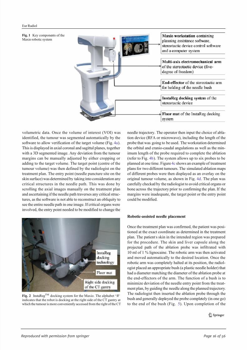
Fig. 1 Key components of the
Maxio robotic system
Fig. 2 InstaRegTM docking system for the Maxio. The alphabet “ R”
indicates that the robot is docking at the right side of the CT gantry at
which the tumour is more conveniently accessed from the right of the CT
Eur Radiol

8/17/2019 Publication Booklet - 130215.pdf
http://slidepdf.com/reader/full/publication-booklet-130215pdf 17/56
Reproduced with permission from springer Page 17 of 56
insertion of the probe, the end effectors were detached from
the probe and the robotic arm was returned to its original
position.
A CT fluoroscopy check examination was performed to
ascertain the location of the ablation probe within the target
volume (Fig. 6). Ablation therapy was then started. For mul-
tiple lesions, the process of needle insertion was repeated as
determined by the treatment plan. The completeness of the
ablation was determined by using multiphasic contrast-enhanced CT immediately after the ablation (Fig. 7).
Patient respiratory motion control
To optimize tumour localization, the baseline CT, CT fluoros-
copy check and post-ablation contrast-enhanced CT were all
performed at the end expiration of the patient, with the airway
disconnected from the ventilator. To minimise liver and hence
ablation probe excursion between the end expiration (when
needle placement was carried out) and the inspiration, the tidal
volumes were set at a high respiratory rate and high O2 level
considered safe by the attending anaesthetist. Muscle relax-
ants were used regularly (especially when doing multiple
placements) to minimise spontaneous breathing of the patient
so that the end expiratory phases were consistent. Otherwise,
the loss of muscle paralysis would impair the end tidal volume
and place the liver at a much lower level.
Data collection and analysis
The orbital and cranio-caudal angulations of the robotic arm
were recorded for each lesion targeted in all patients. The
numbers of adjustment of the needle to achieve satisfactory
positioning within the desired tumour volume were docu-
mented. Deviations of the tip from the centre of the targeted
location were also recorded.
The performance level of the overall procedures was
assessed on a five-point scale (refer Table 1 for the description
of the scoring scheme) by the interventional radiologist for
Fig. 3 Operational flow of the Maxio robotic system for interventional procedures
Eur Radiol

8/17/2019 Publication Booklet - 130215.pdf
http://slidepdf.com/reader/full/publication-booklet-130215pdf 18/56
Reproduced with permission from springer Page 18 of 56
each robotic-assisted thermal ablation. Any complications
related to the use of the robot or the procedures were also
recorded.
The CT fluoroscopic dose (DLP) received by the patients
during the probe placement and ablation was recorded. The
total CT dose from the whole procedure including the multi-
phasic CT studies was also recorded. The doses were then
compared with a random historical control group of 30 pa-
tients (48 lesions) who had liver radiofrequency or microwave
ablation performed by the same radiologist, but without using
the assistance of a robot for probe placement. Statistical anal-
ysis was performed using independent samples T-test with a
95 % confidence interval.
Results
Thermal ablation was successfully completed in 20 patients
with 40 lesions, and confirmed on multiphasic contrast en-
hanced CT. No complications related to either the use of the
robot or the thermal ablation were noted in this study. How-
ever, there was a single case of residual disease after the
ablation. Table 2 demonstrates patient demography and treat-
ment protocols for all the patients.
The total number of lesions treated in each session ranged
from one to a maximum of five lesions (mean of 2±1). The
deepest lesion was 169 mm, while the shallowest was 40 mm
from the skin’s surface. The diameter of the lesions ranged
Fig. 4 Treatment planning and simulation on the Maxio’s workstation. a
Identification and segmentation of the first lesion (labelled as Tumour 1).
The CT images are displayed in axial (middle panel ), coronal (top right
panel ) and sagittal (bottom right panel ) planes, while the 3D simulated
diagram is shown in theleft panelof thetreatment plan. b The entry point,
target point, type of probe and targeted ablation volume were defined by
the interventionalist in the treatment plan. The pink straight line indicates
the trajectory of the ablation probe from the skin surface (entry point ) to
the centre of the target volume (target point ). The ablation volume is
calculated automatically by the software and indicated in the treatment
plan (shown as green spheres covering the tumour). c Segmentation and
treatment planning for the second lesion (labelled as Tumour 2). The
same planning procedures as for Tumour 1 are repeated. The simulation
forTumour1 canstill be seen on theplan as reference. Theindigo straight
line indicates the trajectory of the ablation probe for the second lesion. d
A complete plan for all the three lesions targeted in the same patient. The
simulated needle trajectories are shown in the images and carefully
checked through by the interventionalist prior to the RFA procedures
Eur Radiol

8/17/2019 Publication Booklet - 130215.pdf
http://slidepdf.com/reader/full/publication-booklet-130215pdf 19/56
Reproduced with permission from springer Page 19 of 56
from 5 to 49 mm (mean diameter 19×23 mm). The lesions
were all targeted successfully with the assistance of the robotic
device. The orbital angulations of the robotic arm ranged from
-49.4° to 65.1° (mean positive angulation was 25.1±17.8°;
mean negative angulation was -28.5±16.0°). The cranio-
caudal angulations remained 0° in 24 lesions (15 patients),
while the remaining 16 lesions (five patients) had cranio-
caudal angulations that ranged from −11.9° to 36.8°
(mean positive angulation was 4.3±8.4°; mean negative
angulation was −10.3±2.2°).
Readjustments of the probe were required in 12 of the 20
patients, with only a single repositioning in each of the lesions.
The average number of needle readjustment was 0.8±0.8.
There were no cases of needle reinsertions required. The mean
performance level rated for the robotic-assisted ablation pro-
cedure was 4.4±0.6.
The total DLP per patient for the entire robotic assisted
thermal ablation was 1382±536 mGy.cm, while the CT fluo-
roscopic dose per lesion was 352±228 mGy.cm. When com-
par ed with histori cal dat a from our stand ard abl ation
procedure without the assistance of the robotic device, the
total DLP per patient (n=30) was 1611±708 mGy.cm, while
the CT fluoroscopic dose per lesion was 501± 367 mGy.cm.
Although the dose reduction was not statistically significant
different ( p>0.05), the total DLP, and CT fluoroscopic dose
per lesion were reduced by 14 and 30 %, respectively. Table 3shows the comparison of patient radiation dose for robotic-
assisted versus non-robotic assisted thermal ablation
procedures.
Discussion
Percutaneous CT-guided intervention is an effective method
for image-guided biopsy and tumour ablation. However, the
accuracy of CT-guided needle or probe placement, which is
critical for good diagnostic yield, is highly dependent upon
physician experience. Additionally, the presence of vulnerable
anatomy (such as bowel, nerves or vessels in proximity to the
target) in the needle path has low tolerance for errors in needle
placement. With conventional techniques, challenging tumour
targeting frequently mandates multiple needle adjustments
and intra-procedural imaging, which can prolong procedure
duration as well as increase patient radiation exposure and
procedural risk [6, 7]. Recent advances in robotically guided
interventions have been successful in assisting placement of
needles or related instruments for surgery and interventional
procedures [8 – 13].
For small tumours, such as HCC that are <3 cm, RFA has
been shown to achieve results comparable to surgical resec-
tion. However, its efficacy is reduced for larger tumours [14,
15]. This may in part be attributable to the complexity of
multi-probe placement (simultaneous or sequential), which
is prone to human error, as well as the greater heat sink effect
with larger, more perfused tumours. Accurate probe place-
ment is thus critical for successful large volume composite
ablation and a tumour-free margin [1, 16].
Fig. 6 CT fluoroscopy check examination to verify the location of the ablation probe within the target volume for (a) Tumour 1 (b) Tumour 2
Fig. 5 The intervention radiologist inserted the RFA probe to the target
tumour through the bush located at the end-effector of the robotic arm
Eur Radiol

8/17/2019 Publication Booklet - 130215.pdf
http://slidepdf.com/reader/full/publication-booklet-130215pdf 20/56
Reproduced with permission from springer Page 20 of 56
Navigational software and robotic assistance may offer a
tailored solution to physicians confronting a technically chal-
lenging biopsy or ablation target. Early phantom and clinical
experiences with robotic navigation systems suggest proce-
dural accuracy, reduced procedure time and reduced patient
radiation exposure compared with freehand techniques
[3, 4, 17].
The robot used in this study was a CT-compatible 3D
tumour targeting and needle positioning system for interven-
tional radiology procedures. It is an improved version of its
predecessor, ROBIO Ex (Perfint Healthcare, Florence,
Oregon, USA), which only allows 2D visualization of the
axial images and single needle or probe access per treatment
plan. Additionally, the planning software has a multiplanar
capability, ensuring that better delineation of the centre of the
lesion can be achieved. The system calculates coordinates on
DICOM images from the CT console and guides the
placement of the needle accurately within the body using a
stereotactic device. The depth of needle placement is pre-
determined by the system, but the operator still has the option
of varying this for increased safety. The system can be used for
tumour targeting for abdominal and thoracic interventions,
including biopsy, fine needle aspiration cytology (FNAC),
tumour ablation, pain management and drainage.
While MR-compatible robots have also been developed
and provide many advantages such as non-ionizing
multiplanar imaging with hepato-specific contrast agents and
have the highest liver tumour contrast compared to CT and
ultrasound, they are, however, expensive and require all MR-
compatible equipment and accessories. Hence, access may be
limited and the robots currently only useful for lesions that are
not accessible by other methods [18, 19].
Localisation and navigation systems performed with op-
tical or magnetic localisation spheres require multiple skin
markers to be broadly placed prior to imaging [20]. In
addition, pre-procedure import and processing of the 3D
data to the robot ’s workstation can be complex and time
consuming and occupy a lot of space in the operation room.
Devices that are time consuming in terms of pre-arrangement
and usage are economically unattractive and are therefore not
likely to be used in daily routine. In contrast, the Maxio
requires minimal effort to be mounted and registered to the
CT device using the InstaReg™ technology. The system is
motorised and can be operated by one person. These fea-
tures reduced the complexity of the robotic-guided proce-
dure. We found the overall satisfaction with the performance
of the system to be high. Furthermore, the planning software
on the Maxio system allows the segmentation of the tumour
and subsequent selection of the ablation probe (RFA or
microwave) with the pre-determined ablation volumes to
be overlaid on the target tumour. This adequacy of the
ablation can be checked in all three planes to determine
successful ablation. If this is found to be inadequate, the
tip of ablation needle can be repositioned or a different
probe selected.
Fig. 7 Comparison of (a) Pre-RFA contrast enhanced baseline CT; b
Post-RFA multiphasic contrast-enhanced CT. The ablated volume (red
dashed line) can be clearly seen on the multiphasic contrast-enhanced
scan to verifythe completeness of theablation; and(c) 3-month post-RFA
follow up showing reduction of the coagulation necrosis
Table 1 Scoring scheme for evaluation of the performance level of
robotic-assisted thermal ablation
Score Criteria
5 • Successful ablation
• No needle repositioning
• Superior to the manual needle insertion technique
4 • Successful ablation
• 1 to 2 needle repositionings
• Superior to the manual needle insertion technique
3 • Successful ablation
• 3 to 4 needle repositionings
• Equivalent to the manual needle insertion technique
2 • Successful ablation
• More than 4 needle repositionings or reinsertion of needle is
required
• Inferior to the manual needle insertion technique
1 • Ablation could not be completed due to needle positioning error
• Unsuccessful needle insertion
• Inferior to the manual needle insertion technique
Eur Radiol
8/17/2019 Publication Booklet - 130215.pdf
http://slidepdf.com/reader/full/publication-booklet-130215pdf 21/56
Reproduced with permission from springer Page 21 of 56
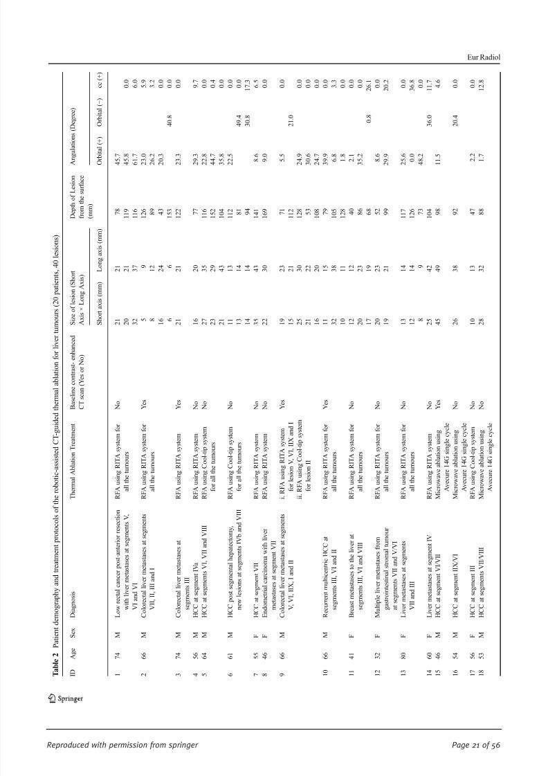
T a b l e 2
P a t i e n t d e m o g r a p h y a n d t r e a t m e n t p r o t o c o l s o f t h e r o b o t i c - a s s i s t e d C T - g u i d e d t h
e r m a l a b l a t i o n f o r l i v e r t u m o u r s ( 2 0 p a t i e n t s , 4 0 l e s i o n s )
I D
A g e
S e x
D i a g n o s i s
T h e r m a l A b l a t i o n T r e a t m e n t
B
a s e l i n e c o n t r a s t - e n h a n c e d
C
T s c a n ( Y e s o r N o )
S i z e o f l e s i o n ( S h o r t
A x i s × L o n g A x i s )
D e p t h o f L e s i o n
f r o m t h e s u r f a c e
( m m )
A n g u l a t i o n s ( D e g r e e )
S h o r t a x i s ( m m ) L
o n g a x i s ( m m )
O r b i t a l ( + )
O r b i t a l ( − )
c c ( + )
1
7 4
M
L o w r e c t a l c a n c e r p o s t - a n t e r i o r r e s e c t i o n
w i t h l i v e r m e t a s t a s e s a t s e g m e n t s V ,
V I a n d V I
R F A u s i n g R I T A s y s t e m f o r
a l l t h e t u m o u r s
N
o
2 1
2
1
7 8
4 5 . 7
2 0
2
1
1 1 9
4 5 . 8
0 . 0
3 2
3
7
1 1 6
6 1 . 7
6 . 0
2
6 6
M
C o l o r e c t a l l i v e r m e t a s t a s e s a
t s e g m e n t s
V I I , I I , I I I a n d I
R F A u s i n g R I T A s y s t e m f o r
a l l t h e t u m o u r s
Y
e s
5
9
1 2 6
2 3 . 0
5 . 9
8
1
2
8 9
2 6 . 2
3 . 2
1 6
2
4
4 3
2 0 . 3
0 . 0
6
6
1 5 3
4 0 . 8
0 . 0
3
7 4
M
C o l o r e c t a l l i v e r m e t a s t a s e s a
t
s e g m e n t s I I I
R F A u s i n g R I T A s y s t e m
Y
e s
2 1
2
1
1 2 2
2 3 . 3
0 . 0
4
5 6
M
H C C a t s e g m e n t I V a
R F A u s i n g R I T A s y s t e m
N
o
1 6
2
0
7 7
2 9 . 3
9 . 7
5
6 4
M
H C C a t s e g m e n t s V I , V I I a n
d V I I I
R F A u s i n g C o o l - t i p s y s t e m
f o r a l l t h e t u m o u r s
N
o
2 7
3
5
1 1 6
2 2 . 8
0 . 0
2 3
2
9
1 5 2
4 4 . 7
0 . 4
2 1
4
3
1 0 4
3 5 . 8
0 . 0
6
6 1
M
H C C p o s t s e g m e n t a l h e p a t e c t o m y ,
n e w l e s i o n s a t s e g m e n t s I
V b a n d V I I I
R F A u s i n g C o o l - t i p s y s t e m
f o r a l l t h e t u m o u r s
N
o
1 1
1
3
1 1 2
2 2 . 5
0 . 0
1 3
1
4
8 1
4 9 . 4
0 . 0
1 4
1
4
9 4
3 0 . 8
1 7 . 3
7
5 5
F
H C C a t s e g m e n t V I I
R F A u s i n g R I T A s y s t e m
N
o
3 5
4
3
1 4 1
8 . 6
6 . 5
8
4 6
F
E n d o m e t r i a l c a r c i n o m a w i t h
l i v e r
m e t a s t a s e s a t s e g m e n t V I I
R F A u s i n g R I T A s y s t e m
N
o
2 2
3
0
1 6 9
9 . 0
0 . 0
9
6 6
M
C o l o r e c t a l l i v e r m e t a s t a s e s a
t s e g m e n t s
V , V I , I I X , I a n d I I
i . R F A u s i n g R I T A s y s t e m
f o r l e s i o n V , V I , I I X a n d I
i i . R F A u s i n g C o o l - t i p s y s t e m
f o r l e s i o n I I
Y
e s
1 9
2
3
7 1
5 . 5
0 . 0
1 5
2
1
1 1 2
2 1 . 0
2 5
3
0
1 2 8
2 4 . 9
0 . 0
2 1
2
2
5 3
3 0 . 6
0 . 0
1 6
2
0
1 0 8
2 4 . 7
0 . 0
1 0
6 6
M
R e c u r r e n t m u l t i c e n t r i c H C C
a t
s e g m e n t s I I I , V I a n d I I
R F A u s i n g R I T A s y s t e m f o r
a l l t h e t u m o u r s
Y
e s
1 1
1
5
7 9
3 9 . 9
0 . 0
3 2
3
8
1 0 5
6 . 8
3 . 3
1 0
1
1
1 2 8
1 . 8
0 . 0
1 1
4 1
F
B r e a s t m e t a s t a s e s t o t h e l i v e r a t
s e g m e n t s I I I , V I a n d V I I I
R F A u s i n g R I T A s y s t e m f o r
a l l t h e t u m o u r s
N
o
1 2
1
2
4 0
2 . 1
0 . 0
2 0
2
3
8 6
3 5 . 2
0 . 0
1 7
1
9
6 8
0 . 8
2 6 . 1
1 2
3 2
F
M u l t i p l e l i v e r m e t a s t a s e s f r o
m
g a s t r o i n t e s t i n a l s t r o m a l t u
m o u r
a t s e g m e n t s V I I a n d V / V I
R F A u s i n g R I T A s y s t e m f o r
a l l t h e t u m o u r s
N
o
2 0
2
3
5 2
8 . 6
0 . 0
1 9
2
1
9 9
2 9 . 9
2 0 . 2
1 3
8 0
F
L i v e r m e t a s t a s e s a t s e g m e n t s
V I I a n d I I I
R F A u s i n g R I T A s y s t e m f o r
a l l t h e t u m o u r s
N
o
1 3
1
4
1 1 7
2 5 . 6
0 . 0
1 2
1
4
1 2 6
0 . 0
3 6 . 8
8
9
7 3
4 8 . 2
0 . 0
1 4
6 0
F
L i v e r m e t a s t a s e s a t s e g m e n t
I V
R F A u s i n g R I T A s y s t e m
N
o
2 5
4
2
1 0 4
3 6 . 0
1 1 . 7
1 5
4 6
M
H C C a t s e g m e n t V I / V I I
M i c r o w a v e a b l a t i o n u s i n g
A v e c u r e 1 4 G s i n g l e c y c l e
Y
e s
4 5
4
9
9 8
1 1 . 5
4 . 6
1 6
5 4
M
H C C a t s e g m e n t I I X / V I
M i c r o w a v e a b l a t i o n u s i n g
A v e c u r e 1 4 G s i n g l e c y c l e
N
o
2 6
3
8
9 2
2 0 . 4
0 . 0
1 7
5 6
F
H C C a t s e g m e n t I I I
R F A u s i n g C o o l - t i p s y s t e m
N
o
1 0
1
3
4 7
2 . 2
0 . 0
1 8
5 3
M
H C C a t s e g m e n t s V I I / V I I I
M i c r o w a v e a b l a t i o n u s i n g
A v e c u r e 1 4 G s i n g l e c y c l e
N
o
2 8
3
2
8 8
1 . 7
1 2 . 8
Eur Radiol

8/17/2019 Publication Booklet - 130215.pdf
http://slidepdf.com/reader/full/publication-booklet-130215pdf 22/56
Reproduced with permission from springer Page 22 of 56
T a b l e 2 ( c o n t i n u e d )
I D
A g e
S e x
D i a g n o s i s
T h e r m a l A b l a t i o n T r e a t m e n t
B
a s e l i n e c o n t r a s t - e n h a n c e d
C
T s c a n ( Y e s o r N o )
S i z e o f l e s i o n ( S h o r t
A x i s × L o n g A x i s )
D e p t h o f L e s i o n
f r o m t h e s u r f a c e
( m m )
A n g u l a t i o n s
( D e g r e e )
S h o r t a x i s ( m m ) L
o n g a x i s ( m m )
O r b i t a l ( + )
O r b i t a l ( − )
c c ( + )
1 9
6 0
F
C o l o r e c t a l l i v e r m e t a s t a s e s
a t s e g m e n t I I I
M i c r o w a v e a b l a t i o n u s i n g
A v e c u r e 1 4 G s i n g l e c y c l e
N
o
1 6
1
8
1 0 8
6 5 . 1
0 . 0
2 0
7 1
M
H C C a t s e g m e n t V
M i c r o w a v e a b l a t i o n u s i n g
A v e c u r e 1 4 G s i n g l e c y c l e
Y
e s
2 2
2
3
8 6
4 4 . 1
0 . 0
M e a n
1 9
2 3
9 9
2 5 . 1
2 8 . 5
4 . 3
S t a n d a r d D e v i a t i o n
8
1 1
3 1
1 7 . 8
1 6 . 0
8 . 4
M i n
5
6
4 0
0 . 0
0 . 8
0 . 0
M a x
4 5
4 9
1 6 9
6 5 . 1
4 9 . 4
3 6 . 8
I D
A n g u l a t i o n s ( D e g r e e )
N u m b e r o f
N e e d l e
I n s e r t i o n s
N u m b e r o f
R e p o s i t i o n i n g /
R e a d j u s t m e n t
P e r f o r m a n c e
L e v e l ( 1
t o 5 , r e f e r t o s c o r i n g
s c h e m e i n T a
b l e 1 )
C T F l u o r o s c o p i c D o s e
( D L P , m G y . c m )
T o t a l C T D o s e
( C T D I v
o l
,
m G y )
T o t a l C T D o s e
( D L P , m G y . c m )
C T F l u o r o s c o p i c
D o s e ,
D L P
p e r L e s i o n
( m G y . c m )
O u t c o m e s
c c ( − )
1
1 1 . 9
3
1
4
1 0 8 3
7 5 3
1 8 6 0
3 6 1
S u c c e s s f u l a b l a t i o n
2
4
2
4
1 7 1 2
1 1 8 9
2 0 8 4
4 2 8
S u c c e s s f u l a b l a t i o n
3
1
0
5
7 7 7
5 4 0
1 1 9 1
7 7 7
S u c c e s s f u l a b l a t i o n
4
1
0
5
1 8 7
1 7 0
1 2 1 8
1 8 7
S u c c e s s f u l a b l a t i o n
5
3
1
4
4 9 5
3 4 4
1 4 5 8
1 6 5
S u c c e s s f u l a b l a t i o n
6
3
1
4
8 7 5
6 0 8
1 0 3 0
2 9 2
S u c c e s s f u l a b l a t i o n
7
1
0
5
1 6 4
1 1 4
8 1 5
1 6 4
S u c c e s s f u l a b l a t i o n
8
1
1
4
6 1 4
4 2 6
1 7 2 5
6 1 4
S u c c e s s f u l a b l a t i o n
9
5
3
3
1 5 9 7
1 1 0 9
2 6 9 9
3 1 9
S u c c e s s f u l a b l a t i o n
8 . 8
Eur Radiol

8/17/2019 Publication Booklet - 130215.pdf
http://slidepdf.com/reader/full/publication-booklet-130215pdf 23/56
Reproduced with permission from springer Page 23 of 56
T a b l e 2 ( c o n t i n u e d )
I D
A n g u l a t i o n s ( D e g r e e )
N u m b e r o f
N e e d l e
I n s e r t i o n s
N u m b e r o f
R e p o s i t i o n i n g /
R e a d j u s t m e n t
P e r f o r m a n c e
L e v e l ( 1
t o 5
, r e f e r t o s c o r i n g
s c h e m e i n T a
b l e 1 )
C T F l u o r o s c o p i c D o s e
( D L P , m G y . c m )
T o t a l C T D o s e
( C T D I v
o l
,
m G y )
T o t a l C T D o s e
( D L P , m G y . c m )
C T F l u o r o s c o p i c
D o s e , D L P
p e r L e s i o n
( m G y . c m )
O u t c o m e s
c c ( − )
1 0
3
1
4
7 1 7
4 9 8
2 0 4 2
2 3 9
S u c c e s s f u l a b l a t i o n
0 . 0
1 1
3
1
4
4 6 1
3 2 0
9 6 9
1 5 4
S u c c e s s f u l a b l a t i o n
1 2
2
2
4
1 4 4 6
1 0 0 5
1 9 9 6
7 2 3
S u c c e s s f u l a b l a t i o n
1 3
3
0
5
1 1 3 6
7 8 9
1 5 5 4
3 7 9
S u c c e s s f u l a b l a t i o n
1 4
1
1
4
2 8 4
1 9 7
8 1 1
2 8 4
S u c c e s s f u l a b l a t i o n
1 5
1
1
4
1 2 8
8 9
8 5 1
1 2 8
S u c c e s s f u l a b l a t i o n
1 6
1
0
5
7 2 9
5 0 8
1 1 4 2
7 2 9
S u c c e s s f u l a b l a t i o n
1 7
1
1
4
5 8 9
1 3 1 2
7 0 1
5 8 9
S u c c e s s f u l a b l a t i o n
1 8
1
0
5
4 5
3 1
1 0 1 8
4 5
S u c c e s s f u l a b l a t i o n
1 9
1
0
5
4 1 8
2 9 0
1 0 8 0
4 1 8
S u c c e s s f u l a b l a t i o n
2 0
1
0
5
5 4
3 7
1 3 9 1
5 4
S u c c e s s f u l a b l a t i o n
M e a n
1 0 . 3
2 . 0
0 . 8
4 . 4
6 7 6
5 1 7
1 3 8 2
3 5 2
S t a n d a r d D e v i a t i o n
2 . 2
1 . 3
0 . 8
0 . 6
5 0 5
3 9 6
5 3 6
2 2 8
M i n
8 . 8
1
0
4
5 4 5
3 1
7 0 1
4 5
M a x
1 1 . 9
5
3
5
1 7 1 2
1 3 1 2
2 6 9 9
7 7 7
F = F e m a l e ; M = M a l e ; H C C = H e p a t o c e l l u l a r c a r c i n o m a ; R F A = R a d i o f r e q u e n c y a b l a t i o
n ; C C = C r a n i a l - c a u d a l a n g l e ; M i n = M i n i m u m ; M a x = M a x i m u m
Eur Radiol

8/17/2019 Publication Booklet - 130215.pdf
http://slidepdf.com/reader/full/publication-booklet-130215pdf 24/56
Reproduced with permission from springer Page 24 of 56
As was previously reported [3], the greater control and ease
of needle placement outside the bore of the CT gantry without
exposure to CT fluoroscopy dose was again a tremendous
benefit. This is especially helpful in patients who are large,
as well as for the lesions that require more lateral access of the
needle. Even though none of the patients in this study required
placement of multiple probes simultaneously, we believe this
system will be truly beneficial when multiple probes/needles
are necessary for the treatment, e.g., Cool-tip RFA needles
with a switching controller. Additionally, robotic-assisted in-
terventions would be useful for those who do not have access
to CT fluoroscopy during the procedures.
Although our study showed no significant differences of
patient radiation dose between robotic-assisted and conven-
tional thermal ablation, this may be related to the expertise of
the operator in this study. Previous studies noted the decreased
accuracy of inexperienced operators when placement of the
needles was performed manually under the guidance of CT
fluoroscopy [21, 22]. Certain impreciseness during manual
needle insertion is unavoidable. The continuous reassessment
and repetitive adjustment of the needle orientation under the
guidance of CT fluoroscopy could lead to an increase in
radiation exposure to the patients as well as the attending staff.
With the assistance of the robotic positioning device, the direct
radiation exposure to the interventionist ’s hands during needle
insertion could be minimized. The radiation exposure to the
operators was not assessed in this study, but theoretically the
staff dose decreases when the CT fluoroscopy dose decreases.
A randomised controlled study with a larger sample size
would be necessary to confirm this.
A critical part of the capability of the Maxio system is in
ensuring accurate co-registration of the planning data sets with
liver volume at the time of needle insertion, as the system is
still not able to compensate for movements of the target
region, especially those caused by respiration, since the
planned trajectory is based on a static-acquired 3D data set.
This co-registration in our practice was achieved by
performing all procedures under general anaesthesia with
intubation and muscle relaxants at the end of expiration, with
the airway disconnected from ventilator-produced consistent
positing. The muscle relaxants were used regularly, especially
when doing multiple placements. Otherwise, the loss of mus-
cle paralysis would impair the end tidal volume and place the
liver at a much lower level. The baseline CT, needle placement
and post-procedure CT acquisitions were all performed at the
end of expiration once the ventilator was disconnected. Others
have suggested that anaesthetic manoeuvres, such as high
frequency jet ventilation to reduce respiratory motion, signif-
icantly reduce radiation dose [23]. However, these systems are
expensive and require a greater skill set. Additionally, we used
low tidal volumes with high respiratory rate and high O2 to
minimize liver excursion and needle movement in the cranio-
caudal direction.
The use of robots to assist in thermal ablation may require a
major change to the current workflow, with additional steps to
the procedure. These include docking the robotic system,
importing the images from the CT console into the worksta-
tion, segmenting the tumour, planning the entry and target
points, inputting the length of the needle, and finally sending
the information to the robotic arm. Thus, there would be a
need to redefine the roles of different members of the medical
team with use of robotic assisted thermal ablation. A compre-
hensive work flow chart, with staff being well trained in
operating the robot, also needs to be established.
In conclusion, we present our early clinical experience of
thermal ablation for primary and secondary liver tumours
using an advanced CT-guided robotic system. The system
showed good accuracy for percutaneous needle placement
for ablative therapy, with a radiation dose comparable to the
historical controls. Even though these preliminary data were
promising, the study was not randomised. A randomised
controlled study with a larger sample size comparing robotic
and non-robotic-assisted thermal ablation needs to be carried
out to determine the outcomes.
Acknowledgements The scientific guarantor of this publication is
Basri Johan Jeet Abdullah. The authors of this manuscript declare rela-
tionships with the following companies: Perfint Healthcare Pvt Ltd,
Florence, Oregon, USA. The authors state that this work has not received
any funding. No complex statistical methods were necessary for this
paper. Institutional Review Board approval was obtained. Written in-
formed consent was obtained from all subjects (patients) in this study.
Approval from the institutional animal care committee was not required
because no animal was used in this study. Some study subjects or cohorts
have been previously reported in the European Congress of Radiology
(ECR), Vienna, on 6 March 2014. Methodology: prospective, case-
control study, performed at one institution.
Table 3 Comparison of total
DLP per patient and CT fluoro-
scopic dose per lesion of robotic-
assisted versus non-robotic-
assisted thermal
ablation procedures
Robotic-assisted
thermal ablation
(n=20)
Non-robotic-assisted
thermal ablation
(control group, n=30)
Dose reduction
with robotic
assistance (%)
P -value
Total DLP per patient (mGy·cm) 1382 ±536 1611 ±708 14 P >0.05
CT fluoroscopic dose per lesion(DLP, mGy·cm)
352±228 501±367 30 P >0.05
Eur Radiol

8/17/2019 Publication Booklet - 130215.pdf
http://slidepdf.com/reader/full/publication-booklet-130215pdf 25/56
Reproduced with permission from springer Page 25 of 56
References
1. Minami Y, Kudo M (2011) Radiofrequency ablation of hepatocellu-
lar carcinoma: a literature review. Int J Hepatol 2011:104685
2. Rhim H et al (2004) Radiofrequency thermal ablation of abdominal
tumours: lessons learned from complications. Radiographics24:41 – 52
3. Abdullah BJ et al (2014) Robot-assisted radiofrequency ablation of
primary and secondary liver tumours: early experience. Eur Radiol
24:79 – 85
4. Koethe Y et al (2014) Accuracy and efficacy of percutaneous biopsy
and ablation using robotic assistance under computed tomography
guidance: a phantom study. Eur Radiol 24:723 – 730
5. Widmann G et al (2012) Frameless stereotactic targeting devices:
technical features, targeting errors and clinical results. Int J Med
Robot 8:1 – 16
6. Magnusson A, Akerfeldt D (1991) CT-guided core biopsy using a
new guidance device. Acta Radiol 32:83 – 85
7. Onik G et al (1988) CT-guided aspirations for the body: comparison
of hand guidance with stereotaxis. Radiology 166:389 – 394
8. Kapur V, Smilowitz NR, Weisz G (2013) Complex robotic-enhanced percutaneous coronary intervention. Catheter Cardiovasc Interv
9. Song SE et al (2012) Biopsy needle artifact localization in MRI-
guided robotic transrectal prostate intervention. IEEE Trans Biomed
Eng 59:1902 – 1911
10. Carrozza JP Jr (2012) Robotic-assisted percutaneous coronary inter-
vention – filling an unmet need. J Cardiovasc Transl Res 5:62 – 66
11. Krieger A et al (2011) An MRI-compatible robotic system with
hybrid tracking for MRI-guided prostate intervention. IEEE Trans
Biomed Eng 58:3049 – 3060
12. Ho HS et al (2009) Robotic ultrasound-guided prostate intervention
device: system description and results from phantom studies. Int J
Med Robot 5:51 – 58
13. Patronik NA, Zenati MA, Riviere CN (2005) Preliminary evaluation
of a mobile robotic device for navigation and intervention on the
beating heart. Comput Aided Surg 10:225 – 232
14. Tiong L, Maddern GJ (2011) Systematic review and meta-
analysis of survival and disease recurrence after radiofre-
quency ablation for hepatocellular carcinoma. Br J Surg 98:
1210 –
122415. Best SL et al (2012) Long-term outcomes of renal tumour radio
frequency ablation stratified by tumour diameter: size matters. J
Urol 187:1183 – 1189
16. Pleguezuelo M et al (2008) TACE versus TAE as therapy for hepa-
tocellular carcinoma
17. Wallach D et al (2014) Comparison of freehand-navigated and
aiming device-navigated targeting of liver lesions. Int J Med Robot
10:35 – 43
18. Kettenbach J et al (2006) Intraoperative and interventional MRI:
recommendations for a safe environment. Minim Invasive Ther
Allied Technol 15:53 – 64
19. Clasen S et al (2007) MR-guided radiofrequency ablation in a
0.2-T open MR system: technical success and technique ef-
fectiveness in 100 liver tumours. J Magn Reson Imaging 26:
1043 –
105220. Hong J et al (2006) Interventional navigation for abdominal therapy
based on simultaneous use of MRI and ultrasound. Med Biol Eng
Comput 44:1127 – 1134
21. Cleary K et al (2002) Technology improvements for image-guided
and minimally invasive spine procedures. IEEE Trans Inf Technol
Biomed 6:249 – 261
22. White CS, Meyer CA, Templeton PA (2000) CT fluoroscopy for
thoracic interventional procedures. Radiol Clin North Am 38:
303 – 322, viii
23. Abderhalden S et al (2011) CT-guided navigation of percutaneous
hepatic and renal radiofrequency ablation under high-frequency jet
ventilation: feasibility study. J Vasc Interv Radiol 22:1275 – 1278
Eur Radiol
8/17/2019 Publication Booklet - 130215.pdf
http://slidepdf.com/reader/full/publication-booklet-130215pdf 26/56
Reproduced with permission from springer Page 26 of 56
INTERVENTIONAL
Robot-assisted radiofrequency ablation of primary
and secondary liver tumours: early experience
Basri Johan Jeet Abdullah & Chai Hong Yeong &
Khean Lee Goh & Boon Koon Yoong & Gwo Fuang Ho &
Carolyn Chue Wai Yim & Anjali Kulkarni
Received: 22 May 2013 /Revised: 1 July 2013 /Accepted: 10 July 2013# The Author(s) 2013. This article is published with open access at Springerlink.com
Abstract
Objective Computed tomography (CT)-compatible robots,
both commercial and research-based, have been developedwith the intention of increasing the accuracy of needle place-
ment and potentially improving the outcomes of therapies in
addition to reducing clinical staff and patient exposure to
radiation during CT fluoroscopy. In the case of highly inac-
cessible lesions that require multiple plane angulations, robot-
ically assisted needles may improve biopsy access and
targeted drug delivery therapy by avoidance of the straight
line path of normal linear needles.
Methods We report our preliminary experience of performing
radiofrequency ablation of the liver using a robotic-assisted
CT guidance system on 11 patients (17 lesions).
Results/Conclusion Robotic-assisted planning and needle
placement appears to have high accuracy, is technically easier
than the non-robotic-assisted procedure, and involves a sig-nificantly lower radiation dose to both patient and support
staff.
Key Points
• An early experience of robotic-assisted radiofrequency ab-
lation is reported
• Robotic-assisted RFA improves accuracy of hepatic lesion
targeting
• Robotic-assisted RFA makes the procedure technically easier
with significant lower radiation dose
Keywords Robot . Radiofrequency ablation . Liver tumour .
CT-guided . Interventional radiology
Introduction
Computed tomography (CT)-compatible robots have been
developed and may soon be integrated into CT-guided renal
mass ablation, hopefully reducing the radiation exposure to
clinical staff and patients during CT fluoroscopy [1]. One
recent study compared a preoperative computer-assisted opti-
cal needle tracking navigation system (KOELIS®, Medtech
Inc, Grenoble, France) with a CT-mounted robotic needle
driver system (AcuBot®, Johns Hopkins University, Balti-more, MD, USA) and found improved accuracy (mean target
distance 1.2 versus 5.8 mm, P <0.0001) and reduced targeting
time (37 versus 108 s, P <0.0001) for the CT-mounted robotic
needle driver system [2]. The authors demonstrated the po-
tential of robotic needle guidance to improve needle interven-
tions, demonstrating superiority over a commercial navigation
system.
Even newer robotic-based image-guided procedures are in
development including specialised robotically controlled
“steerable” needles that may allow for access to previously
B. J. J. Abdullah (*)Department of Biomedical Imaging, Faculty of Medicine, Universityof Malaya, 50603 Kuala Lumpur, Malaysia e-mail: [email protected]
C. H. YeongUniversity of Malaya Research ImagingCentre, Faculty of Medicine,University of Malaya, Kuala Lumpur, Malaysia
K. L. GohDepartment of Internal Medicine, Faculty of Medicine, University of Malaya, 50603 Kuala Lumpur, Malaysia
B. K. YoongDepartment of Surgery, Faculty of Medicine, University of Malaya,50603 Kuala Lumpur, Malaysia
G. F. HoDepartment of Oncology, Faculty of Medicine, University of Malaya, 50603 Kuala Lumpur, Malaysia
C. C. W. YimDepartment of Anesthesia, Faculty of Medicine, University of Malaya, 50603 Kuala Lumpur, Malaysia
A. KulkarniPerfint Healthcare Corporation, Florence, OR 97439, USA
Eur Radiol
DOI 10.1007/s00330-013-2979-7
Clinical Publication - 3

8/17/2019 Publication Booklet - 130215.pdf
http://slidepdf.com/reader/full/publication-booklet-130215pdf 27/56
Reproduced with permission from springer Page 27 of 56
inaccessible anatomical structures for improved biopsy access
and targeted drug delivery therapy by avoidance of the straight
line path of normal linear needles [3]. The increasing com-
plexity invariable leads to increased cost of the devices and
there is a need to balance these conflicting aims.
We report our preliminary experience with a CT or PET-CT-guided robotic positioning system (ROBIO™ EX, Perfint
Healthcare Pvt. Ltd, Florence, OR, USA), which is designed
to assist interventional radiologists in performing procedures
that require precise tool positioning. ROBIO™ E X is a
standalone positioning device that can be moved to the desired
position along the patient table of the CT system. This device
has two linear motions to position the guide to the point of
interest and two angular motions to facilitate the angular entry
of the needle. The system offers several features to help
clinicians to target the tumour and plan for accurate tool
placement. It facilitates targeting and tool placement in deep-
seated lesions requiring orbital, cranio-caudal angulations or a combination of both for thoracic, abdominal and pelvic inter-
ventional procedures.
Materials and methods
This study was granted with medical ethics approval (MEC
no. 949.9) from the Medical Ethics Committee, University of
Malaya Medical Centre, Kuala Lumpur, Malaysia.
Patients
A total of 11 patients with 17 lesions were treated with
radiofrequency ablation (RFA) with the guidance of the
ROBIO™ EX (Perfint Healthcare Pvt. Ltd, Florence, OR,
USA). Six patients had new and recurrent hepatocellular
carcinoma (HCC) and 5 patients had colorectal metastases.
Eight patients were treated with the Cool-tip RFA system
(Valleylab, Boulder, CO, USA) and 3 patients were treated
with the RITA StarBurst® system (Angiodynamics, Latham,
NY, USA). All the lesions were no greater than 3.0 cm in
maximum diameter (the average dimension of the tumour was
2.0×2.2 cm).
All the RFA procedures were performed under general
anaesthesia. Once the patients were intubated, they were
wrapped in reusable immobiliser to minimise patient move-
ment during the procedure. In order to optimise needle place-
ments, the baseline CT, verification of needle placement and
post-procedure CT were performed at end expiration with the
airway disconnected from the ventilator. Additionally, to min-
imise liver excursion between the end expiration (when needle
placement was carried out) and the inspiration, the tidal vol-
umes were set at low with high respiratory rate and high O2
level. Further, to ensure that spontaneous breathing of the
patient would not affect the end expiratory phase, we used
muscle relaxants regularly especially when doing multiple
placements. Otherwise the loss of muscle paralysis would
impair the end tidal volume and place the liver at a much
lower level.
All the patients had non-contrast baseline CT to identify the
lesions. However in 6 patients, because the lesions were small,contrast-enhanced CT studies (example shown in Fig. 1a )
were performed as the baseline to better delineate the location
of the lesions. Post-RFA three-phase CTs (Fig. 1d) were then
performed to assess the completion of the ablation as well as
to act as the baseline for subsequent follow-up. One patient,
however, did not have post-RFA CT because of renal
impairment.
ROBIO™ EX treatment planning
Following baseline CT, the lesions were identified. The CTimages were exported to the ROBIO™ EX workstation for
treatment planning. The target point (centre of the tumour
volume) as well as the entry point (needle puncture site on
skin surface) was determined by the interventional radi-
ologist. The angulations of the needle, the depth of the
lesion as well as the needle trajectory path were calcu-
lated by the ROBIO™ EX workstation and shown on
the treatment plan (Fig. 1b). The plan was carefully checked
by the radiologist to avoid critical organs or bone across the
trajectory. Once confirmed, the plan was sent to the robotic
arm for execution.
Robotic-assisted needle placement
Once the treatment plan was confirmed, the patient was posi-
tioned to the exact coordinates as shown in the ROBIO™ EX
treatment plan. The patient ’s skin was prepared for the proce-
dure in the intended region. The robotic arm was then activat-
ed and it moved automatically to the planned coordinates as
determined in the treatment plan. Once the robotic arm was
completely halted at its position, the radiologist placed an
appropriate bush and bush holder at the end-effector of the
arm (Fig. 2). The skin and liver capsule along the projected
path of the RFA needle were infiltrated with 10 mL of 1 %
lignocaine. The radiologist then inserted the RFA needle
through the bush and pushed the needle to the predetermined
depth where the end-effector was located (Fig. 3). Upon
completion of the insertion of the RFA needle, the robotic
arm was detached from the needle and returned to its original
position. CT fluoroscopy (Fig. 1c) was performed to ensure
that the RFA needle was located within the tumour volume.
RFA therapy was then started and the completeness of the
ablation was determined by using multiphasic contrast-
enhanced CT immediately after the RFA.
Eur Radiol

8/17/2019 Publication Booklet - 130215.pdf
http://slidepdf.com/reader/full/publication-booklet-130215pdf 28/56
Reproduced with permission from springer Page 28 of 56
Data collection and analysis
The orbital and cranio-caudal angulations of the robotic arm
were recorded for each lesion targeted in all patients. The
number of adjustments of the RFA needle was documented.
Deviation of the tip from the centre of the targeted locationwas recorded.
The performance level of the overall procedures was assessed
by the interventional radiologist for each robotic-assisted RFA
on a five-point scale (5=excellent, 4= good, 3 =average, 2 =fair
and 1=poor). Any complications related to the use of the robot
or the RFA were also recorded.
The CT fluoroscopic dose (DLP) received by the patients
during the needle placement and ablation was recorded. The
total dose from the whole procedure including the multiphasic
CT studies was also recorded as the CTDIvol. The doses were
then compared with a random historical control group of pa-
tients who had liver RFA performed by the same radiologist but
without using the assistance of a robot for needle placement.
Results
Radiofrequency ablation was successfully completed in 11
patients with 17 lesions. The deepest lesion was 13.7 cm and
the shallowest was 6.2 cm from the skin surface. The diameter
of the lesions ranged from 1.1 to 3.0 cm. The lesions were all
targeted successfully with the assistance of a robot. No repo-
sitioning of the needle was required in any of the patients. The
orbital angulations of the robotic arm ranged from −49.0° to
46.5° (mean negative angulation was −26.5±24.9°; mean
positive angulation was 27.3± 12.0°). The cranio-caudal an-
gulations remained at 0° in 9 lesions (6 patients) whereas the
remaining 8 lesions (3 patients) had cranio-caudal angulations
of up to 25.0° (mean 7.4±9.9°).
Readjustments of the RFA needle were necessary in
6 lesions, with single readjustment in 4 lesions and two
readjustments in the remaining 2 lesions.
The total DLP and CTDIvol dose for the entire procedure
were 956.09±400.33 mGy cm and 258.00±125.46 mGy, re-
spectively. Compared with historical data from our standard
RFA procedure (n=30), the total DLP and CTDIvol dose were
1,703.93±1,152.37 mGy cm and 632.73±503.06 mGy,
respectively.
All patients had successful ablation confirmed on multi-
phasic contrast-enhanced CT except in one patient who had
renal impairment, which precluded contrast injections.
Post-RFA contrast-enhanced CT was performed in all ex-
cept one patient owing to renal impairment. The CT images
showed successful ablation of the targeted lesions in all pa-
tients. No complications related to either the robot or the RFA
were noted in this study.
The mean performance level rated for the robotic-assisted
RFA procedure was 4.6±0.5, in which the score 5 was
achieved in 7 patients and the score 4 was achieved in the
remaining 4 patients. The patients’ demography, treatment
protocols, radiation dose and evaluation of treatment outcomes
are summarized in Table 1.
Discussion
Image guidance techniques have revolutionised the perfor-
mance of interventions in medicine developed from the use
of advanced imaging investigations. These developments
have been adapted for neurosurgery, orthopaedic procedures,
urological surgery, etc. Current research into the combined
application of image-guided surgery and robots with the com-
plexities of soft tissue registration, operative navigation and
surgical use presents unique engineering challenges and new
knowledge requirements for interventional radiology.
Recent advances in robotically guided interventions have
been successful in assisting placement of needles or related
instruments for surgery or interventional procedures [4 – 9].
Magnetic resonance imaging (MRI)-compatible robots have
also been developed despite their significant engineering chal-
lenges and are continuing to be investigated for prostate biopsy
utilising the potential advantages of multiparametric MRI.
There may also be a future role for improving the accuracy
and precision of radioactive seed placement for prostate can-
cer using the interventional robotic device [10].
The robot used in this study was a CT- or PET-CT-guided
needle positioning system for interventional procedures. The
system calculates coordinates on DICOM images from CT or
PET-CT and guides the placement of the needle accurately
within the body using a robotic arm. The depth of needle
placement is pre-determined by the system but the operator
still has the option of varying this for increased safety. The
system can be used for tumour targeting for abdominal and
thoracic interventions, including biopsy, fine needle aspiration
cytology (FNAC), pain management, drainage and tumour
ablation.
Earlier robotic guidance devices required extensive instal-
lation and were often cumbersome and occupied a lot of space
in the operation room [6, 11, 12]. Devices that are time
consuming in terms of pre-arrangement and usage are eco-
nomically unattractive and are therefore not likely to be used
in daily routine. ROBIO™ EX requires minimal effort to be
mounted and registered to the CT device using the InstaReg™
technology (Perfint Healthcare Pvt Ltd., Florence, OR, USA).
The system is motorised and can be operated by one person.
These features reduced the complexity of the robotic-guided
procedure.
Localisation and navigation of the robots are usually
performed with optical or magnetic localisation spheres,
Eur Radiol

8/17/2019 Publication Booklet - 130215.pdf
http://slidepdf.com/reader/full/publication-booklet-130215pdf 29/56
Reproduced with permission from springer Page 29 of 56
requiring a pre-procedure import and processing of the 3D
data to the robot ’s workstation, which can be a complex and
time-consuming procedure. However in our preliminary ex-
perience with the Robio™ EX, we found the overall satisfac-
tion with the performance to be high. Even though the plan-
ning did take time, it was found to be intuitive and this
increased time was compensated for by greater speed and
accuracy in placing the RFA needles.
Most importantly, the greater control and ease of needle
placement outside the bore of the CT gantry without exposure
to ionising radiation was a tremendous benefit. Both before and
during the needle insertion, neither direct exposure of the inter-
ventionist ’s hands to the radiation beam was involved, nor was
the use of inaccurate holding devices such as forceps necessary.
During the conventional CT-guided RFA procedure, insertion
and placement of the RFA needle are performed manually under
the guidance of real-time CT fluoroscopy. This challenging
procedure needs to be performed by an experienced interven-
tional radiologist and certain impreciseness during the manual
insertion is unavoidable. The continuous reassessment and re-
petitive corrections of the needle orientation under the guidance
of CT fluoroscopy could lead to an increase in radiation expo-
sure to the patients as well as the attending staff. Our study
showed a significant reduction of CT fluoroscopic dose in
patients of 43.9 % (DLP) and 59.2 % (CTDIvol) comparing
robotic and non-robotic-assisted RFA for HCC. This compari-
son might be biased because the radiation dosimetry data for
conventional RFA were collected from our historical HCC
patients in our hospital database. Further the interventional radi-
ologist who participated in this study was aware of the objec-
tive of dose assessment; therefore, there might be unintended
biasness in reducing the fluoroscopic dose. A randomised
controlled study with a larger sample size would be necessary
to confirm this.
Fig. 1 a Contrast-enhanced
baseline CT image shows solitary
colorectal metastases (26.2 mm
diameter) in segment VI. b
Reconstructed CT images (slice
thickness 1 mm) were sent to the
ROBIO™
EX workstation for treatment planning. The
simulated needle trajectory path
was shown on the treatment plan
and verified by the radiologist. c
A CT fluoroscopy check was
carried out to verify the accuracy
of theneedle placement withinthe
target volume. d Post-RFA three-
phase CTs to assess the
completeness of tumour ablation
Fig. 2 The robotic arm was positioned automatically to the exact coor-
dinates according to the treatment plan. The bush and bush holder were
clamped firmly at the end-effector of the robotic arm before insertion of
the RFA needle through the bush
Eur Radiol
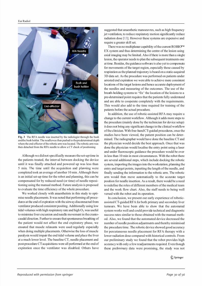
8/17/2019 Publication Booklet - 130215.pdf
http://slidepdf.com/reader/full/publication-booklet-130215pdf 30/56
Reproduced with permission from springer Page 30 of 56
Although we did not specifically measure the set-up time in
the patients treated, the interval between docking the device
until it was finally attached and powered up was less than
5 min. The time until the acquisition and planning were
completed took an average of another 10 min. Although there
is an initial set-up time for the robot and planning, this can be
compensated for by reduced need (or time) of needle reposi-
tioning using the manual method. Future analysis is proposed
to evaluate the time efficiency of the whole procedure.
We worked closely with anaesthetists in this study to opti-
mise needle placements. It was noted that performing all proce-
dures at the end of expiration with the airway disconnected from
ventilator produced consistent positing. Additionally using low
tidal volumes with high respiratory rate and high O2 was useful
to minimise liver excursion and needle movement in the cranio-
caudal direction. Further to ensure that spontaneous breathing of
the patient would not affect the end expiratory phase, we
ensured that muscle relaxants were used regularly especially
when doing multiple placements. Otherwise the loss of muscle
paralysis would impair the end tidal volume and place the liver
at a much lower level. The baseline CT, needle placement and
post-procedure CT acquisitions were all performed at the end of
expiration once the ventilator was disabled. Others have
suggested that anaesthetic manoeuvres, such as high frequency
jet ventilation, to reduce respiratory motion significantly reduce
radiation dose [13]. However these systems are expensive and
require a greater skill set.
There was no multiplanar capability of the current ROBIO™
EX system and thus determining the centre of the lesion usingaxial imaging may be limited. Also if there is more than a single
lesion, the operator needs to plan the subsequent treatments one
at time. Besides, the guidance software is also yet to compensate
for movements of the target region, especially those caused by
respiration as the planned trajectory is based on a static-acquired
3D data set. As the procedure was performed on patients under
arrested end expiration we were able to achieve more consistent
locations of the target lesions and hence accurate deployment of
the needles and measuring of the outcomes. The use of the
breath-holding systems to “fix” the location of the lesions to a
pre-determined point requires that the patients fully understand
and are able to cooperate completely with the requirements.
This would also add to the time required for training of the
patients before the actual procedure.
In addition, the use of robotic-assisted RFA may require a
change to the current workflow. Although it adds more steps to
the procedure (mainly done by the technician for device setup)
it does not bring any significant change in the clinical workflow
of the clinician. With free-hand CT-guided procedures, once the
studies have been viewed, the patient position can be deter-
mined. The radiographer would have done the baseline CT and
the physician would decide the best approach. Once that was
done the physician would localise the entry point using a laser
and under fluoroscopic guidance the procedure would be over
in less than 10 min in most circumstances. With the robot there
are several additional steps, which include docking the robotic
system, importing the images into the workstation, planning the
entry and target points, inputting the length of the needle, and
finally sending the information to the robotic arm. The robotic
arm would then move automatically to the accurate target
position for needle insertion. As a result, there would be a need
to redefine the roles of different members of the medical team
and the work flow chart. Also, the staff needs to being well
versed with the robot and its operation.
In conclusion, we present our early experience of robotic-
assisted CT-guided RFA for both primary and secondary liver
tumours. We have been able to show that the automated
system works well and could provide technical and diagnostic
success rates similar to those obtained with the manual meth-
od. Also, we found that the automated device decreased the
number of needle position adjustments and thereby minimised
the procedure time. The robotic device showed good accuracy
for percutaneous needle placement for RFA therapy with a
lower radiation dose compared with historical controls. From
our preliminary study we found that the robot provides high
accuracy with only a few readjustments required. Even though
these preliminary data were promising, the study was not
Fig. 3 The RFA needle was inserted by the radiologist through the bush
andthe bush holder. The needlewas then pushed to thepredetermined depth
where the end-effector of the robotic arm was located. The robotic arm was
then detached from the RFA needle to allow a CT check of positioning
Eur Radiol
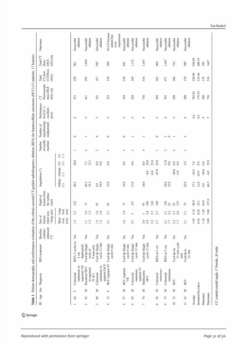
8/17/2019 Publication Booklet - 130215.pdf
http://slidepdf.com/reader/full/publication-booklet-130215pdf 31/56
Reproduced with permission from springer Page 31 of 56
T a b l e 1
P a t i e n t d e m o g r a p h y a n d p e r f o r m a n
c e e v a l u a t i o n o f t h e r o b o t i c - a s s i s t e d C T - g u i d e d r a d i o f r e q u e n c y a b l a t i o n ( R F A ) f o r h e p a t o c
e l l u l a r c a r c i n o m a ( H C C ) ( 1 1 p a t i e n t s ,
1 7 l e s i o n s )
I D
A g e
S e x
D i a g n o s i s
R F A t r e a t m e n t
B a s e l i n e
c o n t r a s t -
e n h a n c e d
C T
S i z e o f
l e s i o n s
( s h o r t a x i s
× l o n g a x i s )
D e p t h o f
l e s i o n s f r o m
t h e s u r f a c e
( m m )
A n g u l a t i o n s ( ° )
N u m b e r
o f n e e d l e
i n s e r t i o n
N u m b e r o f
r e p o s i t i o n i n g /
r e a d j u s t m e n t
P e r f o r m a n c e
l e v e l ( 5 – 1 :
e x c e l l e n t –
p o o r )
C T F l u o r o s c o p i c
d o s e ( D L P ,
m G y c m )
T o t a l
C T d o s e
( C T D I v o l ,
m G y )
T o t a l C T
D o s e ( D L P
,
m G y . c m )
O u t c o m e s
S h o r t
A x i s
( c m )
L o n g
A x i s
( c m )
O r b
i t a l
( + )
O r b i t a l
( − )
C C ( + )
C C ( − )
1
6 4
F
C o l o r e c t a l
m e t a s t a s e s i n
s e g m e n t s V I I
R I T A 3 c y c l e s
a t
4 c m
d e p l o y m e n t
Y e s
1 . 5
2 . 3
1 2 2
4 0 . 5
2 0 . 0
1
0
4
3 3 1
2 2 9
9 6 1
S u c c e s s f u l
a b l a t i o n
2
4 2
M
R e c u r r e n t H C C
i n s e g m e n t s
I V & I
C o o l - t i p S i n g l e
c y c l e o f
8 m i n e a c h
Y e s
1 . 1
1 . 6
7 1
4 6 . 5
7 . 2
2
1
5
4 1 1
2 8 5
1 , 0 3 4
S u c c e s s f u l
a b l a t i o n
1 . 3
1 . 5
1 8 . 3
1 2 . 1
3
8 0
M
C o l o r e c t a l
m e t a s t a s e s i n
s e g m e n t I & I I
C o o l - t i p S i n g l e
c y c l e 1 2 m i n
Y e s
1 . 5
1 . 6
8 1
6 . 0
0 . 0
2
0
5
2 4 1
1 6 7
9 4 2
S u c c e s s f u l
a b l a t i o n
1 . 2
1 . 0
2 9 . 0
0 . 0
4
7 3
F
H C C s e g m e n t V I C o o l - t i p S i n g l e
c y c l e 8 m i n
N o
2 . 1
2 . 1
8 1
1 5 . 0
0 . 0
1
0
5
2 2 3
1 5 6
3 6 9
N o C E b e c a u s e
p a t i e n t h a s
r e n a l
i m p a i r m e n t
5
5 7
M
H C C s e g m e n t
V I I
C o o l - t i p S i n g l e
c y c l e 8 m i n
N o
1 . 6
1 . 9
7 3
1 9 . 0
0 . 0
1
0
5
3 4 4
2 3 8
9 4 1
S u c c e s s f u l
a b l a t i o n
6
5 9
M
C o l o r e c t a l
m e t a s t a s i s
s e g m e n t V I
C o o l - t i p S i n g l e
c y c l e 1 2 m i n
Y e s
2 . 7
3
1 3 7
3 1 . 0
0 . 0
1
1
5
2 4 4
1 6 9
1 , 1 7 2
S u c c e s s f u l
a b l a t i o n
7
7 6
M
M u l t i c e n t r i c
H C C
C o o l - t i p S i n g l e
c y c l e 1 2 m i n
Y e s
3 . 0
3
9 5
2 4 . 0
0 . 0
4
1
4
7 3 6
5 1 6
1 , 4 5 7
S u c c e s s f u l
a b l a t i o n
2 . 4
2 . 4
1 0 4
− 4 . 0
2 4 . 0
2 . 2
2 . 3
1 1 0
− 6 . 0
2 5 . 0
8
5 6
M
C o l o r e c t a l
m e t a s t a s e s
R I T A t o 5 c m
Y e s
2 . 7
2 . 7
1 0 8
− 4 7 . 0
2 4 . 0
1
0
5
5 9 2
2 6 2
9 6 9
S u c c e s s f u l
a b l a t i o n
9
7 3
M
C o l o r e c t a l
m e t a s t a s e s
R I T A t o 5 c m
Y e s
2 . 1
2 . 1
1 3 6
2 4 . 0
1 1 . 0
2
2
4
5 9 1
4 7 1
1 , 6 4 7
S u c c e s s f u l
a b l a t i o n
1 . 7
2 . 2
6 2
3 2 . 0
0 . 0
0
1 0
7 2
M
H C C
C o o l - t i p f o r
1 2 m i n c y c l e
e a c h
N o
2 . 2
2 . 7
9 5
− 4 9 . 0
0 . 0
2
1
5
2 9 8
2 0 6
7 1 6
S u c c e s s f u l
a b l a t i o n
1 . 7
2 . 6
1 3 3
− 2 . 0
0 . 0
1 1
4 3
M
H C C
C o o l - t i p t o
1 2 m i n
N o
2 . 1
2 . 1
7 5
4 2 . 0
3 . 0
1
2
4
2 0 0
1 3 9
3 0 9
S u c c e s s f u l
a b l a t i o n
A v e r a g e
1 . 9 5
2 . 1 8
9 8 . 9
2 7 . 3
− 2 6 . 5
7 . 4
4 . 6
3 8 2 . 8 2
2 5 8 . 0 0
9 5 6 . 0 9
S t a n d a r d D e v i a t i o n
0 . 5 6
0 . 5 4
2 5 . 1
1 2 . 0
2 4 . 9
9 . 9
0 . 5
1 7 9 . 5 4
1 2 5 . 4 6
4 0 0 . 3 3
M i n i m u m
1 . 1 0
1 . 2 0
6 2 . 0
6 . 0
− 4 9 . 0
0 . 0
4
2 0 0
1 3 9
3 0 9
M a x i m u m
3 . 0 0
3 . 0 0
1 3 7 . 0
4 6 . 5
− 4 . 0
2 5 . 0
5
7 3 6
5 1 6
1 6 4 7
C C c r a n i a l - c a u d a l a n g l e ,
F f e m a l e ,
M m a l e
Eur Radiol

8/17/2019 Publication Booklet - 130215.pdf
http://slidepdf.com/reader/full/publication-booklet-130215pdf 32/56
Reproduced with permission from springer Page 32 of 56
randomised. In future a randomised study comparing the
robotic and non-robotic-assisted RFA needs to be carried out
with a larger sample size to determine the cost-effectiveness in
terms of time, cost and radiation dose to both patients and
operators. There is also a need for larger multi-centre studies
for cross-centre comparison.
Acknowledgments This study was supported in part by Perfint
Healthcare Pvt. Ltd,Florence, OR, USAwhich provided research funding
and equipment. The authors had no pertinent conflict of interest and had
unrestricted control of study data.
Open Access This article is distributed under the terms of the Creative
Commons Attribution Noncommercial License which permits any
noncommercial use, distribution, and reproduction in any medium,
provided the original author( s) and the source are credited.
References
1. Mozer P, Troccaz J, Stoianovici D (2009) Urologic robots and future
directions. Curr Opin Urol 19:114 – 119
2. Pollock R, Mozer P, Guzzo TJ et al (2010) Prospects in percutaneous
ablative targeting: comparison of a computer-assisted navigation
system and the AcuBot Robotic System. J Endourol 24:1269 – 1272
3. Rucker DC, Jones BA, Webster RJ 3rd (2010) A geometrically exact
model for externally loaded concentric-tube continuum robots. IEEE
Trans Robot 26:769 – 780
4. Cleary K, Melzer A, Watson V, Kronreif G, Stoianovici D (2006)
Interventional robotic systems: applications and technology state-of-
the-art. Minim Invasive Ther Allied Technol 15:101 – 113
5. Fichtinger G, Fiene JP, Kennedy CW et al (2008) Robotic assistance
for ultrasound-guided prostate brachytherapy. Med Image Anal
12:535 – 545
6. Onogi S, Morimoto K, Sakuma I et al (2005) Development of theneedle insertion robot for percutaneous vertebroplasty. Med Image
Comput Comput Assist Interv 8:105 – 113
7. Penzkofer T, Isfort P, Bruners P et al (2010) Robot arm based flat
panel CT-guided electromagnetic tracked spine interventions: phan-
tom and animal model experiments. Eur Radiol 20:2656 – 2662
8. Rasmus M, Huegli RW, Bilecen D, Jacob AL (2007) Robotically
assisted CT-based procedures. Minim Invasive Ther Allied Technol
16:212 – 216
9. Zangos S, Melzer A, Eichler K et al (2011) MR-compatible assis-
tance system for biopsy in a high-field-strength system: initial results
in patients with suspicious prostate lesions. Radiology 259:903 – 910
10. Bonekamp D, Jacobs MA, El-Khouli R, Stoianovici D, Macura KJ
(2011) Advancements in MR imaging of the prostate: from diagnosis
to interventions. Radiographics 31:677 – 703
11. Tovar-Arriaga S, Tita R, Pedraza-Ortega JC, Gorrostieta E, Kalender WA (2011) Development of a robotic FD-CT-guided navigation
system for needle placement-preliminary accuracy tests. Int J Med
Robot 7:225 – 236
12. Yanof J, Haaga J, Klahr P et al (2001) CT-integrated robot for
interventional procedures: preliminary experiment and computer-
human interfaces. Comput Aided Surg 6:352 – 359
13. Abderhalden S, Biro P, Hechelhammer L, Pfiffner R, Pfammatter T
(2011) CT-guided navigation of percutaneous hepatic and renal
radiofrequency ablation under high-frequency jet ventilation: feasi-
bility study. J Vasc Interv Radiol 22:1275 – 1278
Eur Radiol

8/17/2019 Publication Booklet - 130215.pdf
http://slidepdf.com/reader/full/publication-booklet-130215pdf 33/56
Reproduced with permission from springer Page 33 of 56
INTERVENTIONAL
Preliminary clinical experience with a dedicated
interventional robotic system for CT-guided biopsies of lunglesions: a comparison with the conventional manual technique
Michele Anzidei & Renato Argirò & Andrea Porfiri & Fabrizio Boni & Marco Anile &
Fulvio Zaccagna & Domenico Vitolo & Luca Saba & Alessandro Napoli & Andrea Leonardi &
Flavia Longo & Federico Venuta & Mario Bezzi & Carlo Catalano
Received: 22 May 2014 /Revised: 24 September 2014 /Accepted: 14 November 2014# European Society of Radiology 2014
AbstractObjective Evaluate the performance of a robotic system for
CT-guided lung biopsy in comparison to the conventional
manual technique.
Materials and methods One hundred patients referred for CT-
guided lung biopsy were randomly assigned to group A
(robot-assisted procedure) or group B (conventional proce-
dure). Size, distance from entry point and position in lung of
target lesions were evaluated to assess homogeneity differ-
ences between the two groups. Procedure duration, dose
length product (DLP), precision of needle positioning, diag-
nostic performance of the biopsy and rate of complications
were evaluated to assess the clinical performance of the ro- botic system as compared to the conventional technique.
Results All biopsies were successfully performed. The size
( p=0.41), distance from entry point ( p=0.86) and position in
lung ( p=0.32) of target lesions were similar in both groups( p=0.05). Procedure duration and radiation dose were signif-
icantly reduced in group A as compared to group B ( p=
0.001). Precision of needle positioning, diagnostic perfor-
mance of the biopsy and rate of complications were similar
in both groups ( p=0.05).
Conclusion Robot-assisted CT-guided lung biopsy can be
performed safely and with high diagnostic accuracy, reducing
procedure duration and radiation dose in comparison to the
conventional manual technique.
Key Points
• CT-guided biopsy is the main procedure to obtain diagnosis
in lung tumours.• The robotic device facilitates percutaneous needle place-
ment under CT guidance.
• Robot-assisted CT-guided lung biopsy reduces procedure
duration and radiation dose.
Keywords Robot . Lung biopsy . Lung cancer .
CT-guidance . Interventional radiology
Introduction
CT-guided lung biopsy is the procedure of choice to obtain
diagnoses in patients with pulmonary lesions suggestive of
malignancy at imaging [1 – 3]. Following the recent advances
in targeted therapies, biopsy of unresectable lung lesions has
also become necessary in order to assess genetic mutations in
unresectable non-small cell cancers (NSCLC), with core bi-
opsy usually being preferred to aspiration cytology owing to
the larger specimens made available for molecular analysis
[4]. CT-guided lung biopsy can be performed either with the
step-and-shoot or the fluoroscopic technique: the step-and-
M. Anzidei (*) : R. Argirò : A. Porfiri : F. Boni : F. Zaccagna :
A. Napoli : A. Leonardi : M. Bezzi : C. Catalano
Department of Radiological, Oncological and Anatomopathological
Sciences - Radiology – Sapienza, University of Rome, Viale Regina
Elena 324, 00161 Rome, Italy
e-mail: [email protected]
M. Anile : F. Venuta
Department of Thoracic Surgery – Sapienza, University of Rome,
Rome, Italy
D. Vitolo
Department of Radiological, Oncological and Anatomopathological
Sciences - Pathology – Sapienza, University of Rome, Rome, Italy
L. Saba
Department of Radiology, Azienda Ospedaliero Universitaria
(A.O.U.), di Cagliari-Polo di Monserrato, Monserrato, Italy
F. Longo
Department of Radiological, Oncological and Anatomopathological
Sciences - Oncology – Sapienza, University of Rome, Rome, Italy
Eur Radiol
DOI 10.1007/s00330-014-3508-z
Clinical Publication - 4
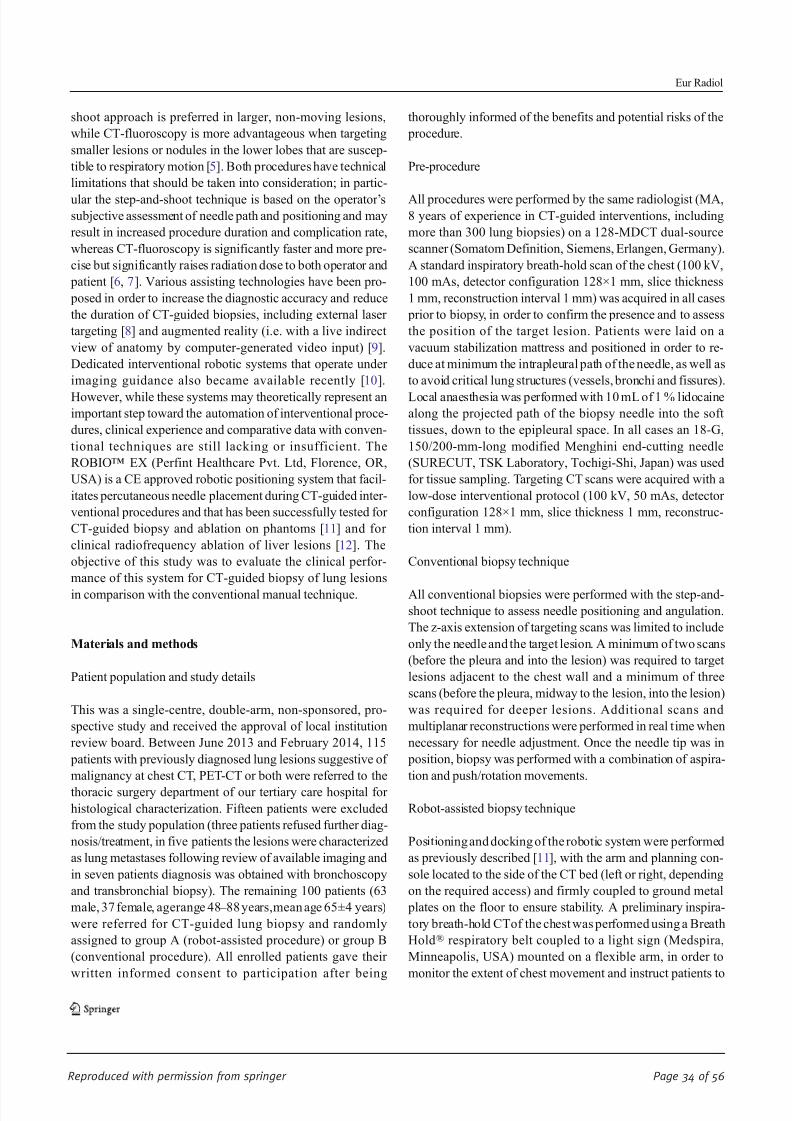
8/17/2019 Publication Booklet - 130215.pdf
http://slidepdf.com/reader/full/publication-booklet-130215pdf 34/56
Reproduced with permission from springer Page 34 of 56
shoot approach is preferred in larger, non-moving lesions,
while CT-fluoroscopy is more advantageous when targeting
smaller lesions or nodules in the lower lobes that are suscep-
tible to respiratory motion [5]. Both procedures have technical
limitations that should be taken into consideration; in partic-
ular the step-and-shoot technique is based on the operator ’ssubjective assessment of needle path and positioning and may
result in increased procedure duration and complication rate,
whereas CT-fluoroscopy is significantly faster and more pre-
cise but significantly raises radiation dose to both operator and
patient [6, 7]. Various assisting technologies have been pro-
posed in order to increase the diagnostic accuracy and reduce
the duration of CT-guided biopsies, including external laser
targeting [8] and augmented reality (i.e. with a live indirect
view of anatomy by computer-generated video input) [9].
Dedicated interventional robotic systems that operate under
imaging guidance also became available recently [10].
However, while these systems may theoretically represent animportant step toward the automation of interventional proce-
dures, clinical experience and comparative data with conven-
tional techniques are still lacking or insufficient. The
ROBIO™ EX (Perfint Healthcare Pvt. Ltd, Florence, OR,
USA) is a CE approved robotic positioning system that facil-
itates percutaneous needle placement during CT-guided inter-
ventional procedures and that has been successfully tested for
CT-guided biopsy and ablation on phantoms [11] and for
clinical radiofrequency ablation of liver lesions [12]. The
objective of this study was to evaluate the clinical perfor-
mance of this system for CT-guided biopsy of lung lesions
in comparison with the conventional manual technique.
Materials and methods
Patient population and study details
This was a single-centre, double-arm, non-sponsored, pro-
spective study and received the approval of local institution
review board. Between June 2013 and February 2014, 115
patients with previously diagnosed lung lesions suggestive of
malignancy at chest CT, PET-CT or both were referred to the
thoracic surgery department of our tertiary care hospital for
histological characterization. Fifteen patients were excluded
from the study population (three patients refused further diag-
nosis/treatment, in five patients the lesions were characterized
as lung metastases following review of available imaging and
in seven patients diagnosis was obtained with bronchoscopy
and transbronchial biopsy). The remaining 100 patients (63
male, 37 female, agerange 48 – 88 years,mean age 65±4 years)
were referred for CT-guided lung biopsy and randomly
assigned to group A (robot-assisted procedure) or group B
(conventional procedure). All enrolled patients gave their
written informed consent to participation after being
thoroughly informed of the benefits and potential risks of the
procedure.
Pre-procedure
All procedures were performed by the same radiologist (MA,8 years of experience in CT-guided interventions, including
more than 300 lung biopsies) on a 128-MDCT dual-source
scanner (Somatom Definition, Siemens, Erlangen, Germany).
A standard inspiratory breath-hold scan of the chest (100 kV,
100 mAs, detector configuration 128×1 mm, slice thickness
1 mm, reconstruction interval 1 mm) was acquired in all cases
prior to biopsy, in order to confirm the presence and to assess
the position of the target lesion. Patients were laid on a
vacuum stabilization mattress and positioned in order to re-
duce at minimum the intrapleural path of the needle, as well as
to avoid critical lung structures (vessels, bronchi and fissures).
Local anaesthesia was performed with 10 mL of 1 % lidocainealong the projected path of the biopsy needle into the soft
tissues, down to the epipleural space. In all cases an 18-G,
150/200-mm-long modified Menghini end-cutting needle
(SURECUT, TSK Laboratory, Tochigi-Shi, Japan) was used
for tissue sampling. Targeting CT scans were acquired with a
low-dose interventional protocol (100 kV, 50 mAs, detector
configuration 128×1 mm, slice thickness 1 mm, reconstruc-
tion interval 1 mm).
Conventional biopsy technique
All conventional biopsies were performed with the step-and-
shoot technique to assess needle positioning and angulation.
The z-axis extension of targeting scans was limited to include
only the needle and the target lesion. A minimum of two scans
(before the pleura and into the lesion) was required to target
lesions adjacent to the chest wall and a minimum of three
scans (before the pleura, midway to the lesion, into the lesion)
was required for deeper lesions. Additional scans and
multiplanar reconstructions were performed in real time when
necessary for needle adjustment. Once the needle tip was in
position, biopsy was performed with a combination of aspira-
tion and push/rotation movements.
Robot-assisted biopsy technique
Positioning and docking of the robotic system were performed
as previously described [11], with the arm and planning con-
sole located to the side of the CT bed (left or right, depending
on the required access) and firmly coupled to ground metal
plates on the floor to ensure stability. A preliminary inspira-
tory breath-hold CTof the chest was performed using a Breath
Hold® respiratory belt coupled to a light sign (Medspira,
Minneapolis, USA) mounted on a flexible arm, in order to
monitor the extent of chest movement and instruct patients to
Eur Radiol
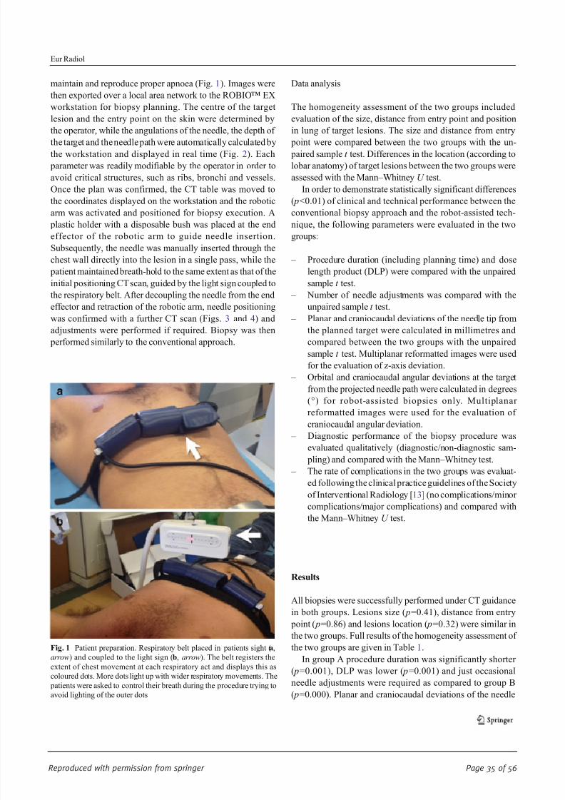
8/17/2019 Publication Booklet - 130215.pdf
http://slidepdf.com/reader/full/publication-booklet-130215pdf 35/56
Reproduced with permission from springer Page 35 of 56
maintain and reproduce proper apnoea (Fig. 1). Images were
then exported over a local area network to the ROBIO™ EX
workstation for biopsy planning. The centre of the target
lesion and the entry point on the skin were determined by
the operator, while the angulations of the needle, the depth of
the target and the needle path were automatically calculated bythe workstation and displayed in real time (Fig. 2). Each
parameter was readily modifiable by the operator in order to
avoid critical structures, such as ribs, bronchi and vessels.
Once the plan was confirmed, the CT table was moved to
the coordinates displayed on the workstation and the robotic
arm was activated and positioned for biopsy execution. A
plastic holder with a disposable bush was placed at the end
effector of the robotic arm to guide needle insertion.
Subsequently, the needle was manually inserted through the
chest wall directly into the lesion in a single pass, while the
patient maintained breath-hold to the same extent as that of the
initial positioning CT scan, guided by the light sign coupled to
the respiratory belt. After decoupling the needle from the end
effector and retraction of the robotic arm, needle positioning
was confirmed with a further CT scan (Figs. 3 and 4) and
adjustments were performed if required. Biopsy was then
performed similarly to the conventional approach.
Data analysis
The homogeneity assessment of the two groups included
evaluation of the size, distance from entry point and position
in lung of target lesions. The size and distance from entry
point were compared between the two groups with the un- paired sample t test. Differences in the location (according to
lobar anatomy) of target lesions between the two groups were
assessed with the Mann – Whitney U test.
In order to demonstrate statistically significant differences
( p<0.01) of clinical and technical performance between the
conventional biopsy approach and the robot-assisted tech-
nique, the following parameters were evaluated in the two
groups:
– Procedure duration (including planning time) and dose
length product (DLP) were compared with the unpaired
sample t test.
– Number of needle adjustments was compared with the
unpaired sample t test.
– Planar and craniocaudal deviations of the needle tip from
the planned target were calculated in millimetres and
compared between the two groups with the unpaired
sample t test. Multiplanar reformatted images were used
for the evaluation of z-axis deviation.
– Orbital and craniocaudal angular deviations at the target
from the projected needle path were calculated in degrees
(°) for robot-assisted biopsies only. Multiplanar
reformatted images were used for the evaluation of
craniocaudal angular deviation.
– Diagnostic performance of the biopsy procedure was
evaluated qualitatively (diagnostic/non-diagnostic sam-
pling) and compared with the Mann – Whitney test.
– The rate of complications in the two groups was evaluat-
ed following the clinical practice guidelines of the Society
of Interventional Radiology [13] (no complications/minor
complications/major complications) and compared with
the Mann – Whitney U test.
Results
All biopsies were successfully performed under CT guidance
in both groups. Lesions size ( p=0.41), distance from entry
point ( p=0.86) and lesions location ( p=0.32) were similar in
the two groups. Full results of the homogeneity assessment of
the two groups are given in Table 1.
In group A procedure duration was significantly shorter
( p=0.001), DLP was lower ( p=0.001) and just occasional
needle adjustments were required as compared to group B
( p=0.000). Planar and craniocaudal deviations of the needle
Fig. 1 Patient preparation. Respiratory belt placed in patients sight (a,
arrow) and coupled to the light sign (b, arrow). The belt registers the
extent of chest movement at each respiratory act and displays this as
coloured dots. More dots light up with wider respiratory movements. The
patients were asked to control their breath during the procedure trying to
avoid lighting of the outer dots
Eur Radiol
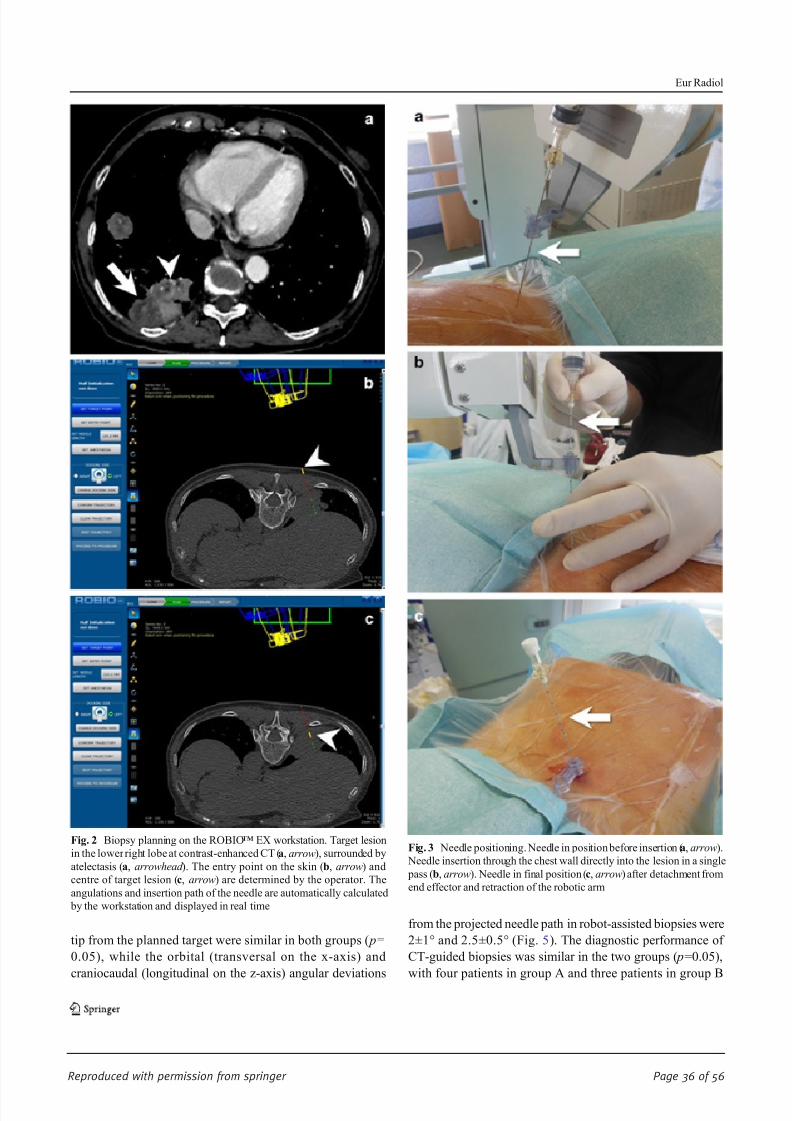
8/17/2019 Publication Booklet - 130215.pdf
http://slidepdf.com/reader/full/publication-booklet-130215pdf 36/56
Reproduced with permission from springer Page 36 of 56
tip from the planned target were similar in both groups ( p=
0.05), while the orbital (transversal on the x-axis) and
craniocaudal (longitudinal on the z-axis) angular deviations
from the projected needle path in robot-assisted biopsies were
2±1° and 2.5±0.5° (Fig. 5). The diagnostic performance of
CT-guided biopsies was similar in the two groups ( p=0.05),
with four patients in group A and three patients in group B
Fig. 2 Biopsy planning on the ROBIO™ EX workstation. Target lesion
in the lower right lobe at contrast-enhanced CT (a, arrow), surrounded by
atelectasis (a, arrowhead ). The entry point on the skin (b, arrow) and
centre of target lesion (c, arrow) are determined by the operator. The
angulations and insertion path of the needle are automatically calculated
by the workstation and displayed in real time
Fig. 3 Needle positioning. Needle in position before insertion (a, arrow).
Needle insertion through the chest wall directly into the lesion in a single
pass (b, arrow). Needle in final position (c, arrow) after detachment from
end effector and retraction of the robotic arm
Eur Radiol

8/17/2019 Publication Booklet - 130215.pdf
http://slidepdf.com/reader/full/publication-booklet-130215pdf 37/56
Reproduced with permission from springer Page 37 of 56
requiring re-biopsy due to inadequate quality of the biopsy
sample. The rate of complications was comparable in the two
groups ( p=0.05); there were three (6 %) cases of pneumotho-
rax in group A and two (4 %) cases of pneumothorax in group
B requiring chest tube drainage and prolonged hospitalization.
Minor complications (including small pneumothorax not re-
quiring therapy and self-limiting peri-lesional haemorrhages)occurred in two (4 %) cases in group A and four (7 %) in
group B. Full results of the assessment of the clinical and
technical performance of the two groups are given in Table 2.
Discussion
Imaging-guided interventional techniques currently represent
a fundamental tool in diagnosis and treatment of oncologic
pathologies. Among the various guidance modalities, CT is
the method of choice in the chest region owing to its excellent
spatial and contrast resolution for the visualization of lung parenchyma, airways and cardiovascular structures that safely
allows biopsy of lung and mediastinal lesions, percutaneous
tube placement and thermal ablation of lung tumours. The
conventional technique for CT-guided interventional proce-
dures requires a trial-and-error method with the step-and-
shoot approach, or the application of a real-time fluoroscopic
monitoring in order to visualize and modify the path of
needles and percutaneous probes. Even if the clinical perfor-
mance of conventional approaches is highly reliable in expert
hands [4 – 7], these methods present well-known technical
limitations and their successful application depends signifi-
cantly on operators’ manual skill and experience. In order to
reduce such operator dependence, several assisting devices
have been developed and tested in clinical practice, including
external laser [8] or optical [14] targeting systems that project
and/or guide the needle path onto the skin surface, electro-magnetic tracking with image fusion [15] and augmented
reality system under infrared guidance that display a real-
time simulation of needle movements [9]. Preliminary reports
are encouraging, but it should be noted that the success of
these technologies is highly dependent on the integration
between the assisting software/hardware, the CT system and
the operator, with increased complexity and costs as compared
to conventional techniques. Moreover, with the approaches
mentioned above the dependence on operator experience is
reduced but not completely eliminated, not mentioning the
need for adequate training. On the other hand, the use of
medical robots for surgical or imaging-guided proceduresallows extremely accurate tool guidance with stable access,
leading to increased precision, accuracy and reproducibility in
a variety of applications, including percutaneous ablations,
biopsies, orthopaedic fixture placement, hollow viscera or
solid organ access [10]. While earlier robots required exten-
sive installation and were often cumbersome to operate, being
time consuming and economically disadvantageous [16, 17],
more recent systems, such as the ROBIO™ EX, require
minimal effort to be mounted and registered to the imaging
Fig. 4 Positioning confirmation after control scan, immediately before
biopsy. Adjacent slices demonstrate overlapping between the planned
needle path ( green line) and the actual needle position at the end of
insertion. Robot-assisted biopsy allowed correct sampling of tumour
tissue avoiding atelectasis. Final histological diagnosis was
adenocarcinoma
Table 1 Full results of the homogeneity assessment of the two groups
Parameter Group A Group B p value
Lesion size (mm) 40.7±23.9 (range 15 – 150) 35.5 ±25 (range 13.5 – 160) 0.41
Distance from Entry point (mm) 73.1 ±30.7 (range 20 – 135) 72.1 ±21.6 (range 18 – 117) 0.86
Lesion location (according to lobar anatomy) RUL (n 11) RUL (n 9) 0.32
LUL (n 6) LUL (n 8)
ML (n 3) ML (n 2)
RLL (18) RLL (16)
LLL (12) LLL (15)
Values are expressed as average±standard deviation
RUL right upper lobe, LUL left upper lobe, ML middle lobe, RLL right lower lobe, LLL left lower lobe
Eur Radiol

8/17/2019 Publication Booklet - 130215.pdf
http://slidepdf.com/reader/full/publication-booklet-130215pdf 38/56
Reproduced with permission from springer Page 38 of 56
device [11], reducing the complexity of the procedure. Also
the fully automated movement of the robotic arm represents a
relevant advantage that removes the need for manual or joy-
stick adjustments in the pretreatment phase that are necessary
with other devices [18, 19] and may further complicate the
clinical workflow. From a clinical point of view, our studydemonstrated in a large patient population that the presented
robotic system facilitates CT-guided lung biopsies, with re-
sults that are substantially in line with previous reports on
biopsies in phantoms [11] and clinical radiofrequency ablation
of liver lesions [12]. It should be considered that, apart from
these two preliminary studies performed with the same robotic
platform, there is no literature evidence of large clinical series
of robot-assisted CT-guided interventions, in particular for
what regards chest procedures; hence, an indirect comparison
with the performance of different robotic devices is currently
impossible. In our single-centre experience, the precision in
lesion targeting, the diagnostic performance of the biopsy
sampling and the rate of complications in the robot-assisted
procedures were comparable to those of conventional biop-
sies, with accurate needle positioning and very few adjustment
required even in lesions as small as 15 mm, but the use of the
robot significantly reduced procedure duration and radiation
dose in comparison to the unassisted technique. This observa-
tion is particularly relevant, since in our study all procedures
were performed by an operator with previous experience of
more than 300 conventional CT-guided lung biopsies and,
notwithstanding this expertise, significant reduction of proce-
dure duration and radiation dose were in any case obtained in
robot-assisted procedures as compared to the conventional
technique. In this regard, future work should aim to evaluate
when and how operators with different levels of experience
may benefit from robot assistance in daily clinical routine, and
assess potential differences in the clinical performance of
robot-assisted procedures between expert and non-expert
Fig. 5 Biopsy of a deep solitary lung nodule in the right upper lobe. The
maximum transverse diameter of the nodule was 10 mm and its
craniocaudal size was 15 mm. Planning CT demonstrates the desiredneedle path and tip positioning (a, arrowhead ). Control CT scan after
needle positioning shows a slight angular deviation of the needle tip
resulting in a 1.5-mm deviation from the planned path ( b, arrowhead ).
Notwithstanding the deviation, biopsy was successfully performed
without further needle adjustments, achieving final histological
diagnosis of adenocarcinoma
Table 2 Full results of the assessment of the clinical and technical performance of the two groups
Parameter Group A Group B p value
Procedure duration (min) 20.1 ± 11.3 (range 10 – 31) 31.4±10.2 (range 18 – 42) 0.001
DLP (mGy) 324±114.5 (range 117 – 386) 541.2±446.8 (range 334 – 589) 0.001
Number of needle adjustments 2.7± 2.6 (range 1 – 4) 6±4 (range 2 – 12) 0.000
Deviations on the x and y axes (mm) 2.3 ± 1.1 ( x) 2.5±1.5 ( y) (range 1 – 8) 3.0±1.3 ( x) 2.1±1.6 ( y) (range 2 – 11) 0.05
Orbital (o) and craniocaudal (c)
deviations (°)
2±1° (o) 1.5±0.5° (c) N/A N/A
Final diagnosis 18 ADCA, 9 SCC, 6 SCLC, 10 mets,
3 benignant
15 ADCA, 10 SCC, 7 SCLC, 14 mets,
1 benignant
0.05
4 rebiopsy (1 ADCA, 2 SCC, 1 SCLC) 3 rebiopsy (2 ADCA, 1 SCC)
Complications (%) 10.4 11 0.05
Values are expressed as average±standard deviation
ADCA adenocarcinoma, SCC squamous cell carcinoma, SCLC small cell carcinoma, mets metastases, N/A not acquired
Eur Radiol

8/17/2019 Publication Booklet - 130215.pdf
http://slidepdf.com/reader/full/publication-booklet-130215pdf 39/56
Reproduced with permission from springer Page 39 of 56
radiologists. Moreover, even if a dedicated cost-analysis is
currently unavailable, it could be speculated that the use of
interventional robotic systems will be probably even more
beneficial in clinical settings in which financial resources or
time for appropriate training of interventional radiologists is
lacking, pushing less expert, non-interventional operators to perform simple imaging-guided procedures. Even if these
preliminary results are encouraging, this study has some lim-
itations. First, the sample size was not determined in advance
with a power analysis in order to increase the relevance of the
statistical evaluation. Moreover, a statistical subanalysis based
on the anatomic characteristics of the target lesions (size,
distance to pleura and position in lung) was not performed;
hence we cannot provide clustered data on system perfor-
mance for the biopsy of smaller and hardly accessible lesions,
which should be the ideal target for robot-assisted procedures.
Last, an independent evaluation of the status of the lung
parenchyma surrounding the target lesions was not available
in order to assess the influence of local pulmonary factors
(emphysema, fibrosis, bronchiectases) on the rate of compli-
cations in the two groups, even if this parameter was probably
not influential, since our complication rates do not differ from
those reported in the literature [4 – 7]. Notwithstanding these
limitations, the results of our study demonstrate that robot-
assisted CT-guided lung biopsy is a safe and accurate inter-
ventional technique that can reduce procedure duration and
radiation dose in comparison to the conventional manual
approach even in expert hands. Further studies are needed to
confirm these data and to evaluate the performance of robot-
assisted interventional procedures in other clinical scenarios.
Acknowledgments The scientific guarantor of this publication is Dr.
Michele Anzidei. The authors of this manuscript declare no relationships
with any companies whose products or services may be related to the
subject matter of the article. The authors state that this work has not
received any funding. Dr. Fulvio Zaccagna kindly provided statistical
advice for this manuscript. Institutional review board approval was ob-
tained. Written informed consent was obtained from all subjects (patients)
in this study. No study subjects or cohorts have been previously reported.
Methodology: prospective, randomised controlled trial, performed at one
institution.
References
1. MacMahon H, Austin JH, Gamsu G, Herold CJ, Jett JR, Naidich DP,
Patz EF Jr, Swensen SJ, Fleischner Society (2005) Guidelines for
management of small pulmonary nodules detected on CT scans: a
statement from the Fleischner Society. Radiology 237:395 – 400
2. Naidich DP, Bankier AA, MacMahon H, Schaefer-Prokop CM,
Pistolesi M, Goo JM, Macchiarini P, Crapo JD, Herold CJ, Austin
JH, Travis WD (2013) Recommendations for the management of
subsolid pulmonari nodules detected at CT: a statement from the
Fleischner Society. Radiology 266:304 – 317
3. Gould MK, Donington J, Lynch WR, Mazzone PJ, Midthun DE,
Naidich DP, Wiener RS (2013) Evaluation of individuals with pul-
monary nodules: when is it lung cancer? Diagnosis and management
of lung cancer, 3rd ed: American College of Chest Physicians
evidence-based clinical practice guidelines. Chest 143:e93S – e120S
4. Tuna T, Ozkaya S, Dirican A, Findik S, Atici AG, Erkan L (2013)
Diagnostic efficacy of computed tomography-guided transthoracicneedle aspiration and biopsy in patients with pulmonary disease.
Onco Targets Ther 6:1553 – 1557
5. Lal H, Neyaz Z, Nath A, Borah S (2012) CT-guided percutaneous
biopsy of intrathoracic lesions. Korean J Radiol 13:210 – 226
6. Kim GR, Hur J, Lee SM, Lee HJ, Hong YJ, Nam JE, Kim HS, Kim
YJ, Choi BW, Kim TH, Choe KO (2011) CT fluoroscopy-guided
lung biopsy versus conventional CT-guided lung biopsy: a prospec-
tive controlled study to assess radiation doses and diagnostic perfor-
mance. Eur Radiol 21:232 – 239
7. Prosch H, Stadler A, Schilling M, Bürklin S, Eisenhuber E, Schober
E, Mostbeck G (2012) CT fluoroscopy-guided vs. multislice CT
biopsy mode-guided lung biopsies: accuracy, complications and ra-
diation dose. Eur J Radiol 81:1029 – 1033
8. Hong CW, Xu S, Imbesi KL, Wood BJ (2013) Integrated laser-guided
CT biopsy. Clin Imaging 37:1135 –
11379. Grasso RF, Faiella E, Luppi G, Schena E, GiurazzaF, DelVescovoR,
D'Agostino F, Cazzato RL, Beomonte Zobel B (2013) Percutaneous
lung biopsy: comparison between an augmented reality CT naviga-
tion system and standard CT-guided technique. Int J Comput Assist
Radiol Surg 8:837 – 848
10. Kettenbach J, Kronreif G, Melzer A, Fichtinger G, Stoianovici D,
Cleary K (2007) Ultrasound-, CT- and MR-guided robot-assisted
interventions. In: Neri E, Caramella D, Bartolozzi C (eds) Image
processing in radiology: current applications. Springer, Heidelberg,
pp 391 – 404
11. Koethe Y, Xu S, Velusamy G, Wood BJ, Venkatesan AM (2014)
Accuracy and efficacy of percutaneous biopsy and ablation using
robotic assistance under computed tomography guidance: a phantom
study. Eur Radiol 24(3):723 – 730
12. Abdullah BJ, Yeong CH, Goh KL, Yoong BK, Ho GF, Yim CC,Kulkarni A (2014) Robot-assisted radiofrequency ablation of primary
and secondary liver tumours: early experience. Eur Radiol 24:79 – 85
13. Sacks D, McClenny TE, Cardella JF, Lewis CA (2003) Society of
Interventional Radiology clinical practice guidelines. J Vasc Interv
Radiol 14:S199 – S202
14. von Jako CR, Zuk Y, Zur O, Gilboa P (2013) A novel accurate
minioptical tracking system for percutaneous needle placement.
IEEE Trans Biomed Eng 60:2222 – 2225
15. Krücker J, Xu S, Glossop N, Viswanathan A, Borgert J, Schulz H,
Wood BJ (2007) Electromagnetic tracking for thermal ablation and
biopsy guidance: clinical evaluation of spatial accuracy. J Vasc Interv
Radiol 18:1141 – 1150
16. Tovar-Arriaga S, Tita R, Pedraza-Ortega JC, Gorrostieta E, Kalender
WA (2011) Development of a robotic FD-CT-guided navigation
system for needle placement-preliminary accuracy tests. Int J MedRobot 7:225 – 236
17. Yanof J, Haaga J, Klahr P (2001) CT-integrated robot for interven-
tional procedures: preliminary experiment and computer human in-
terfaces. Comput Aided Surg 6:352 – 359
18. Schulz B, Eichler K, Siebenhandl P et al (2012) Accuracy and speed
of robotic assisted needle interventions using a modern cone beam
computed tomography intervention suite: a phantom study. Eur
Radiol 23:198 – 204
19. Su L-M, Stoianovici D, Jarrett TW et al (2002) Robotic percutaneous
access to the kidney: comparison with standard manual access. J
Endourol 16:471 – 475
Eur Radiol
8/17/2019 Publication Booklet - 130215.pdf
http://slidepdf.com/reader/full/publication-booklet-130215pdf 40/56
Reproduced with permission from springer Page 40 of 56
INTERVENTIONAL
Accuracy and efficacy of percutaneous biopsy and ablation
using robotic assistance under computed tomographyguidance: a phantom study
Yilun Koethe & Sheng Xu & Gnanasekar Velusamy &
Bradford J. Wood & Aradhana M. Venkatesan
Received: 25 July 2013 /Revised: 24 September 2013 /Accepted: 10 October 2013# European Society of Radiology (outside the USA) 2013
Abstract
Objective To compare the accuracy of a robotic interventional
radiologist (IR) assistance platform with a standard freehand
technique for computed-tomography (CT)-guided biopsy and
simulated radiofrequency ablation (RFA).
Met hod s The accuracy of freehand single-pass needle
insertions into abdominal phantoms was compared with
insertions facilitated with the use of a robotic assistance
platform (n =20 each). Post-procedural CTs were analysed
for needle placement error. Percutaneous RFA was simulated
by sequentially placing five 17-gauge needle introducers into
5-cm diameter masses (n =5) embedded within an abdominal
phantom. Simulated ablations were planned based on pre-
procedural CT, before multi-probe placement was executed
freehand. Multi-probe placement was then performed on the
same 5-cm mass using the ablation planning software and
robotic assistance. Post-procedural CTs were analysed to
determine the percentage of untreated residual target.
Results Mean needle tip-to-target errors were reduced with
use of the IR assistance platform (both P <0.0001). Reduced
percentage residual tumour was observed with treatment
planning ( P =0.02).
Conclusion Improved needle accuracy and optimised probe
geometry are observed during simulated CT-guided biopsy
and percutaneous ablation with use of a robotic IR assistance
platform. This technology may be useful for clinical CT-
guided biopsy and RFA, when accuracy may have an impact
on outcome.
Key points:
• A recently developed robotic intervention radiology
assistance platform facilitates CT-guided interventions.
• Improved accuracy of complex needle insertions is
achievable.
• IR assistance platform use can improve target ablation
coverage.
Keywords Interventional radiology . Robotics .
Image-guided biopsy . Ablation techniques
Abbreviations
IR Interventional radiologist
RFA Radiofrequency ablation
Y. Koethe : S. Xu : B. J. Wood : A. M. Venkatesan
Center for Interventional Oncology, NIH Clinical Center, National
Institutes of Health, Bethesda, MD, USA
Y. Koethe : B. J. Wood : A. M. Venkatesan
Radiology and Imaging Sciences, NIH Clinical Center, National
Institutes of Health, Bethesda, MD, USA
Y. Koethe
Duke University School of Medicine, Durham, NC, USA
G. Velusamy
Perfint Healthcare Pvt. Ltd., Chennai, India
A. M. Venkatesan (*)
Center for Interventional Oncology, Radiology and Imaging
Sciences, NIH Clinical Center, National Institutes of Health, 10
Center Drive, Building 10 CRC, Room 1C369, MSC 1182,
Bethesda, MD 20892, USA
e-mail: [email protected]
Eur Radiol
DOI 10.1007/s00330-013-3056-y
Clinical Publication - 5Clinical Publication - 5

8/17/2019 Publication Booklet - 130215.pdf
http://slidepdf.com/reader/full/publication-booklet-130215pdf 41/56
Reproduced with permission from springer Page 41 of 56
Introduction
P e rc u ta n e o u s c o mp u te d -to mo g ra p h y (CT )-g u id e d
interventions can be used effectively for image-guided biopsy
and tumour ablation [1]. CT-guided biopsy can effectively
obtain samples for histological assessment of a tumour, and
is advantageous given its minimally invasive approach and
ability to enable visualisation of deep tissues [2]. However, the
accuracy of CT-guided needle placement, which influences
diagnostic yield, is highly dependent upon physician
experience. Vulnerable anatomy (such as bowel, nerves
or vessels in proximity to the target) has low tolerance for
needle placement errors. With conventional techniques,
challenging biopsy targets frequently mandate multiple needle
adjustments and intra-procedural imaging, which can prolong
procedure duration, and increase patient radiation exposure
and procedural risk [3, 4]. Needle-based thermal ablation such
as radiofrequency ablation (RFA) induces coagulative
necrosis of tumours such as hepatocellular carcinoma, hepatic
metastases and renal cell carcinoma [1, 3, 5 – 8]. While RFA
has been shown to achieve results comparable to surgical
resection for small tumours, such as hepatocellular
carcinomas <3 cm, its efficacy has been shown to be reduced
for larger tumours [6, 9, 10]. In addition to greater heat sink
effect with larger, more perfused tumours, reduced efficacy of
RFA for large tumours may be in part attributable to multi-
probe placement complexity, which is prone to human error.
This is critical for successful large volume composite ablation,
however, in order to achieve ablation of both tumour and an
intended tumour-free margin [11, 12].
Navigational software and robotic assistance may offer a
tailored solution to physicians confronting a technically
challenging biopsy or ablation target. Early phantom and
clinical experience with robotic navigation systems suggest
procedural accuracy, reduced procedure time and reduced
patient radiation exposure compared with freehand techniques
[13 – 19]. Experience with software systems enabling ablation
planning has also been favourably described [20, 21]. In this
study, an IR assistance platform was evaluated that combines
navigational software and robotic guidance to facilitate
percutaneous biopsy and ablation probe placement. Needle
placement accuracy and ablation efficacy were assessed in
abdominal phantoms.
Materials and methods
Robotic IR assistance platform device
Device specifications, emergency options
The robotic IR assistance platform (MAXIO; Perfint
Healthcare, Chennai, India) has dimensions of 850 mm×
800 mm×1,350 mm (length × width × height) in the parked
position) and 850 mm× 800 mm ×1,800 mm when docked at
the CT table side, with the robotic arm positioned over the CT
table. The weight of the device is 250 kg and it is propelled via
four way swivel wheels. The device requires between
approximately 3-4 min total to be physically moved from its
parked position to CT tableside, to dock the device and boot it
up. It requires approximately the same amount of time to
switch off the device, undock and move it to the parking
location identified inside the CT suite. The device’s robotic
arm takes approximately 30-45 s to move from its initial
position to the position to clamp the needle guide.
Two emergency shut off functions are available for this
device. One is an emergency switch physically located on the
robotic arm, whose actuation will stop all device axis
movement. If the needle guide is already clamped the device
will release the clamped needle holder immediately and the
device will be restored to a “safe state”, during which all the
movement related components of the device are stopped and
no further movement is possible before intervention by the
user to reset the position values and command the device to
move again. The device also has a Cancel Movement option
in the software which the user may click on using the device’s
track pad. This will also stop all movements and restore the
device to its “safe state”.
Physical docking, optical registration and DICOM data
retrieval
Registration between the robotic IR assistance platform and
the CT table occurs via a mechanical docking mechanism,
optical registration and tilt sensing (MAXIO; Perfint,
Chennai, India) (Fig. 1a ). Provided all three components of
registration (mechanical docking, optical registration and tilt
sensing) are successfully executed, the platform permits
pro cedures to be car ried out. Con sistent doc kin g and
registration of the robotic device abrogates the need for
robot-to-CT registration with each use. The platform’s
computer console receives DICOM formatted images from
the CT console via an Ethernet cable, and displays the images
on its planning and navigation software.
Biopsy and ablation planning software
The system has a track pad for the user to interact with the
computer. Using the track pad, the physician selects the needle
or probe type and length from a series of drop-down menus on
the computer console integrated into this device. Needle/probe
trajectory and biopsy or ablation target are selected directly on
the DICOM data transferred to the device’s computer console.
DICOM CT data may be displayed in the axial as well as
sagittal and coronal planes by the graphical user interface. The
physician operator plans a biopsy with the navigational
Eur Radiol
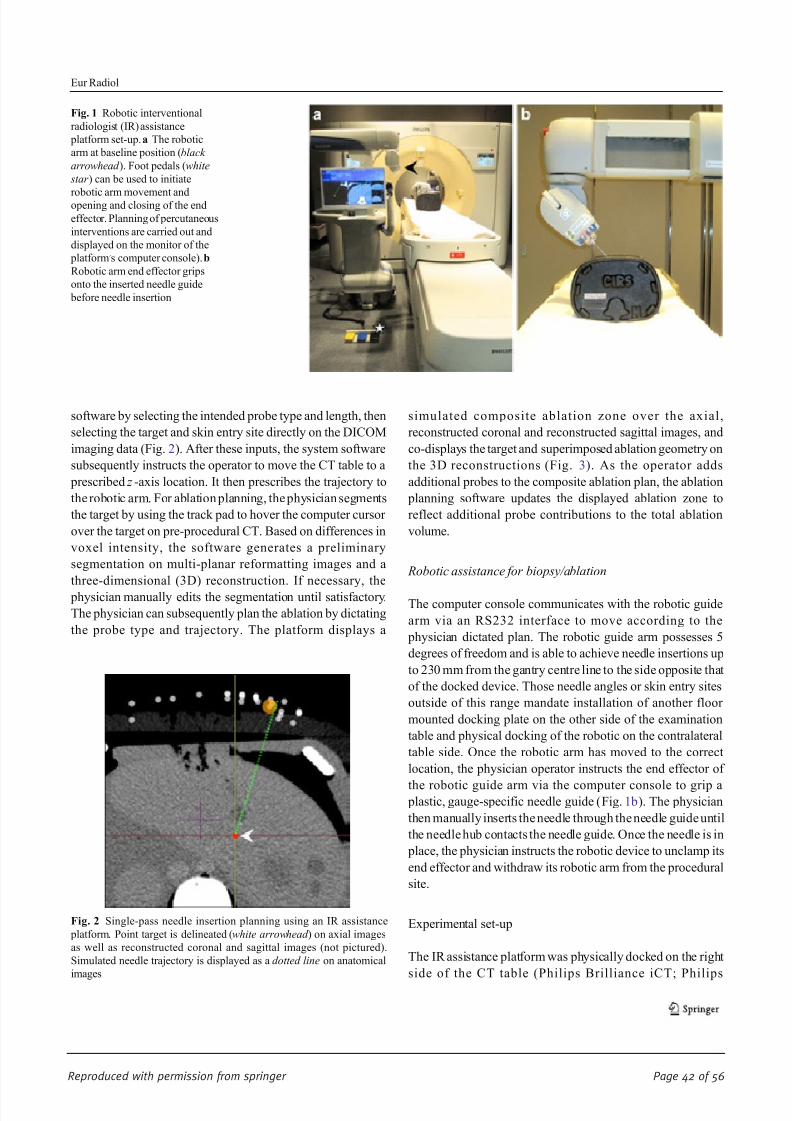
8/17/2019 Publication Booklet - 130215.pdf
http://slidepdf.com/reader/full/publication-booklet-130215pdf 42/56
Reproduced with permission from springer Page 42 of 56
software by selecting the intended probe type and length, then
selecting the target and skin entry site directly on the DICOM
imaging data (Fig. 2). After these inputs, the system software
subsequently instructs the operator to move the CT table to a
prescribed z -axis location. It then prescribes the trajectory to
the robotic arm. For ablation planning, the physician segments
the target by using the track pad to hover the computer cursor
over the target on pre-procedural CT. Based on differences in
voxel intensity, the software generates a preliminary
segmentation on multi-planar reformatting images and a
three-dimensional (3D) reconstruction. If necessary, the
physician manually edits the segmentation until satisfactory.
The physician can subsequently plan the ablation by dictating
the probe type and trajectory. The platform displays a
simulated composite ablation zone over the axial,
reconstructed coronal and reconstructed sagittal images, and
co-displays the target and superimposed ablation geometry on
the 3D reconstructions (Fig. 3). As the operator adds
additional probes to the composite ablation plan, the ablation
planning software updates the displayed ablation zone to
reflect additional probe contributions to the total ablation
volume.
Robotic assistance for biopsy/ablation
The computer console communicates with the robotic guide
arm via an RS232 interface to move according to the
physician dictated plan. The robotic guide arm possesses 5
degrees of freedom and is able to achieve needle insertions up
to 230 mm from the gantry centre line to the side opposite that
of the docked device. Those needle angles or skin entry sites
outside of this range mandate installation of another floor
mounted docking plate on the other side of the examination
table and physical docking of the robotic on the contralateral
table side. Once the robotic arm has moved to the correct
location, the physician operator instructs the end effector of
the robotic guide arm via the computer console to grip a plastic, gauge-specific needle guide (Fig. 1b). The physician
then manually inserts the needle through the needle guide until
the needle hub contacts the needle guide. Once the needle is in
place, the physician instructs the robotic device to unclamp its
end effector and withdraw its robotic arm from the procedural
site.
Experimental set-up
The IR assistance platform was physically docked on the right
side of the CT table (Philips Brilliance iCT; Philips
Fig. 1 Robotic interventional
radiologist (IR) assistance
platform set-up. a The robotic
arm at baseline position (black
arrowhead ). Foot pedals (white
star ) can be used to initiate
robotic arm movement andopening and closing of the end
effector. Planning of percutaneous
interventions are carried out and
displayed on the monitor of the
platform’s computer console). b
Robotic arm end effector grips
onto the inserted needle guide
before needle insertion
Fig. 2 Single-pass needle insertion planning using an IR assistance
platform. Point target is delineated (white arrowhead ) on axial images
as well as reconstructed coronal and sagittal images (not pictured).
Simulated needle trajectory is displayed as a dotted line on anatomical
images
Eur Radiol

8/17/2019 Publication Booklet - 130215.pdf
http://slidepdf.com/reader/full/publication-booklet-130215pdf 43/56
Reproduced with permission from springer Page 43 of 56
Healthcare, Cleveland, OH, USA) (Fig. 1). Image acquisition
properties were based on the manufacturer ’s recommendations
(5-mm section thickness, 1-mm reconstruction interval).
Optically opaque abdominal phantoms (Triple Modality 3D
Abdominal Phantom Model 057; CIRS, Norfolk, VA, USA)
were used for needle and probe placement. All needle
insertions were performed by an attending interventional
radiologist with 7 years of percutaneous biopsy and ablation
experience.
Needle placement for biopsy
Twenty pairs of virtual point targets and skin entry points with
a mean entry-to-target distance of 11.0 cm (range, 10.2 –
11.5 cm) were selected on pre-procedural CT using custom
software (intGuide; National Institutes of Health, Bethesda,
MD, USA). Each pair of target and skin entry points
comprised a complex multi-angle needle trajectory with
angular deviations in the x , y and z directions. Single-pass
needle insertions were performed using an 18-gauge, 15-cm
needle (Biomedical SRL, Firenze, Italy). Insertions were first
performed using a freehand technique, employing only the CTgantry laser light and the markings of the CT grid placed over
the phantom during pre-procedural imaging and for
localisation (Fast Find Grid; Webb Manufacturing
Corporation, Philadelphia, PA, USA). Insertions were
subsequently performed with the use of the IR assistance
platform. Neither intra-procedural needle adjustments nor
intra-procedural CTs were permitted for either approach.
Needle placement for composite ablation simulation
Custom opaque abdominal phantoms (CIRS, Norfolk, VA,
USA) were designed containing multiple 5-cm diameter
embedded masses meant to simulate 3-cm diameter tumours
and surrounding 1-cm tumour-free margins. For each target,
five simultaneous RFA electrode placements were planned
with the intent of maximising simulated ablation of the target
(i.e. simulated tumour and tumour-free margin). A total of five
17-gauge, 15-cm needle introducers (Cardinal Health, Dublin,
OH, USA), simulating 15-cm long, 3-cm active tip CoolTip
RFA Electrodes (Covidien, Dublin, Ireland), were inserted
into the 5-cm diameter embedded targets. Ablations were first
planned manually on the CT console after obtaining an initial
CT of the phantom. Needle insertions were then executed
freehand, employing only the CT gantry laser light and the
markings of the CT grid placed over the phantom during pre-
procedural imaging for localisation. Probe placement was
subsequently planned and executed using the IR assistance
pla tform’s ablation planning software. Neither needle
adjustments nor intra-procedural CTs were permitted between
needle insertions. Post-procedural imaging documenting
needle locations and positions was obtained subsequent to
needle placement for each technique.
Image analysis
Custom software (intGuide; National Institutes of Health,
Bethesda, MD USA) was used to select the needle tip on the
post-procedural CTs obtained after biopsy needle insertion.
The custom software subsequently calculated the Euclidian
distance between the tip of the needle and the virtual target,
corresponding to the “tip-to-target distance.”
Custom research software (OncoNav; National Institutes of
Health, Bethesda, MD, USA) derived from Medical Image
Processing, Analysis and Visualization (MIPAV) software
(National Institutes of Health) was employed for simulated
ablation analysis [22]. The target was manually segmented,
and each needle displayed on post-procedural CT was
Fig. 3 Ablation planning on an IR assistance platform. Ablation
planning software displays axial images (a) as well as reconstructedcoronal and sagittal images (not pictured). After tumour segmentation
(segmented tumour: white arrow, a ), probes are planned and their
trajectories displayed on the anatomical images (probes: solid/dotted
lines in a ). The predicted composite ablation zone is superimposed onto
the segmented tumour on both multiplanar images and on a 3D shaded
surface display (composite ablation zone: black arrow in a , white
arrowheads in b )
Eur Radiol

8/17/2019 Publication Booklet - 130215.pdf
http://slidepdf.com/reader/full/publication-booklet-130215pdf 44/56
Reproduced with permission from springer Page 44 of 56
manually outlined. Ablation zone geometry and size was
subsequently predicted based on needle placement and
manufacturer-prescribed ablation size (3.6× 3.7 cm ellipsoidal
coverage per needle) [23]. The software subtracted the
composite ablation volume from the segmented target volume
thereby calculating the percentage residual non-ablated target (Fig. 4).
Statistics
Paired t- tests were used to compare the differences in needle
tip-to-target distance for simulated biopsy. Paired t -tests were
also used to compare the differences in percentage residual
target for simulated ablation. 95 % confidence intervals were
assumed (α ≤0.05). Descriptive statistics were employed to
calculate mean entry-to-target distance and mean angular
deviation for simulated biopsy.
Results
Mean entry-to-target distance was 11.0±3.8 cm (range, 10.2 –
11.5 cm) for needle insertions simulating percutaneous biopsy.
A shorter mean needle tip-to-target distance was observed
with use of the IR assistance platform compared with the
freehand technique (6.5±2.5 mm vs 15.8±9.2 mm,
respectively; P <0.0001; Fig. 5a ). Mean absolute angular
deviation off the z -axis was 53° (range -68° to 74°). Mean
absolute angular deviation off the y -axis was 46° (range -42°
to 56°).
For simulated composite ablation, a lower average
percentage of residual target was observed with use of the
IR assistance platform (13.0±4.0 %) compared with the
freehand technique (25.1±10.9 %; P =0.03; Fig. 5b).
Discussion
In this study, we evaluated the accuracy and efficacy of an
integrated IR assistance platform for multi-angle needle
placements and ablation planning. Improved needle accuracy
compared with freehand technique was demonstrated with the
use of this IR assistance platform for challenging, single-pass,
multi-angle needle trajectories.
F i g. 4 Analysis of ablation coverage. Representative image
demonstrates residual target volume (black asterisks ) and ablated
volumes (white ovals) around inserted needles (white arrows)
Fig. 5 Scatter plots demonstrate the distribution of tip-to-target distance
(a) for freehand and IR assistance platform-guided needle insertion. b
Before-after plots demonstrate percentage residual tumour for each target
using the freehand technique and the IR assistance platform
Eur Radiol

8/17/2019 Publication Booklet - 130215.pdf
http://slidepdf.com/reader/full/publication-booklet-130215pdf 45/56
Reproduced with permission from springer Page 45 of 56
Improved needle placement accuracy may clinically
translate into decreased complication rates and greater
sampling success for biopsies [6, 9, 10, 24]. Out-of-plane
trajectories have traditionally been challenging to plan with
CT guidance. If the entry point and the target are in two
different planes, only one can be visualised at a time, makingit challenging to plan multi-angle trajectories. Compared with
traditional CT guidance, cone beam CT or fluoroscopically
guided interventions offer an advantage of enabling
orthogonal and oblique projections of the skin entry site and
target [11, 17]. With this novel IR assistance platform, the
challenges of multi-angle visual planning are further
circumvented. The skin entry and the target points can be
directly planned on the computer console of the IR assistance
platform, which subsequently executes the planned trajectory,
without requiring physician calculations of entry-to-target
distance and angulation.
Reduced variability of needle placement accuracy was also
noted with IR assistance platform guidance compared with the
freehand technique. A potential explanation for this
observation is that freehand needle accuracy is dependent
upon physician comfort and skill with a particular angulation
and insertion depth, whereas the IR assistance platform does
not face this limitation, being presumably equally accurate for
both simple and complex angles. Although not evaluated in
this study, a novice with limited experience in executing
complex multi-angle trajectories might be able to acquire
visual, and some tactile experience, by first executing the
trajectory with use of this IR assistance platform. The
platform’s role as a training tool remains an interesting area
for further investigation. While treatment planning is
frequently used in image-guided external beam radiation
therapy and brachytherapy, ablation zone simulation and
planning for interventional oncology remains relatively novel
[25]. In this study, the use of the ablation planning component
of this IR assistance platform was associated with greater
target coverage and reduced residual target compared with
the freehand technique.
One limitation of the ablation planning component of this
platform that should be noted is that the simulated ablation
volumes are manufacturer-predicted isotherms, derived
largely from ex vivo data. The actual ablation volume may
vary depending on tissue type, energy source, electrode, and
local microscopic and regional perfusion factors [26].
Navigati on and guidance tools have the pote ntia l to
mitigate imperfect operator spatial awareness and hand-eye
coordination. Non-robotic navigation and guidance devices
that assist physicians include electromagnetic (EM) tracking,
optical tracking, laser guidance and cone beam CT fusion.
Optical and EM tracking provide information on real-time
needle position and orientation, but mandate the use of costly
disposables such as EM or optically tracked needles [27, 28].
In addition, they may require extensive pre-procedural
registration, which can be consuming as the location of
fiducial markers and EM field generators (or cameras for
optical tracking) must be accommodated intra-procedurally
[13 – 17, 29]. Laser guidance has no physical needle guide to
steady the needle during insertion. Cone beam CT fusion
requires installation of a C-arm and other hardware that mayoccupy an entire IR suite.
The IR assistance platform used in this study, in
comparison, requires minimal time for docking and
registration. Like other robotic devices, it can also accurately
orientate and guide multi-angle needle insertions without
necessitating the use of custom needles. Schulz et al. [17].
have recently described a robotic device that assists
per cutan eou s nee dle inser tion for con e bea m CT and
f l u or o s c op y - g ui d e d p r o c ed u r e s ( i S Y S 1 ; i S Y S
Medizintechnik, Kitzbuehel, Austria). This device is mounted
to a small platform beneath the CT table, and has 4 degrees of
fre e d o m. A p h a n to m s tu d y e mp lo y in g th is d e v ic e
demonstrated that accurate needle placement can be achieved
in a timely manner (average error, 1.1 mm; average duration
of procedure, 3:59 min). Solomon et al. [13] and Patriciu et al.
[14] have also recently described a robotic system with a total
of 11 degrees of freedom that is mounted on a large frame
attached to and overlying the CT table (PAKY-RCM; Johns
Hopkins, Baltimore, MD, USA). This device has a rolling
dowel mechanism that can advance a needle without
physician assistance. Use of this device for percutaneous
interventions demonstrated accuracy (average error,
1.7 mm), reduced overall procedure time, number of probe
passes, and patient an d phy sician radiatio n exposure
compared with conventional techniques.
Compared with other robotic devices for image-guided
interventions, this IR assistance platform also has a large range
of achievable needle angles, ranging from -90° to 90° in both
lateral and craniocaudal directions, provided installation of
floor mounted plates and docking on either site of the
examination table has been enabled. The automated aspect
of this system’s robotic arm offers additional unique
advantages. Whereas the robotic guide arm of other existing
devices must be manually positioned in the vicinity of the
target before subsequent end effector localisation is achieved
automatically or via joystick use, the robotic guide arm of this
platform automatically moves from its docked position to the
skin entry point based on the physician dictated plan [17, 20,
21, 30]. As this platform abrogates the need for manual
movement of the device after initial registration and docking,
the physician can focus on the biopsy and ablation planning
steps instead of manually moving the robot during the
procedure. Additional advantages of this platform include its
mobility, as it can be wheeled away from the CT when not in
use.
The limitations of this robotic platform are similar to those
of other robotic guidance devices. Once docked, this platform
Eur Radiol

8/17/2019 Publication Booklet - 130215.pdf
http://slidepdf.com/reader/full/publication-booklet-130215pdf 46/56
Reproduced with permission from springer Page 46 of 56
limits physical access on one side of the CT table near the
gantry. In addition, physical docking of the device limits the
overall range of craniocaudal targets that are accessible.
Another limitation is the fact that tactile experience
diminished when using this device, as the needle holder
clamps tightly around the needle. Furthermore, as we onlyreport a phantom study, we were not able to evaluate this
technique in the in vivo environment, when specific
challenges like target, patient and respiratory motion must be
surmounted. But in this initial study phantom study, we were
interested to evaluate the ability of this system to facilitate
complex needle angle insertions compared with an
experienced operator ’s freehand single pass insertion. It
should also be noted that a single pass needle insertion is not
the standard procedure for complex clinical needle
placements. It would be of interest to pursue a follow-up study
wherein the operator was permitted multiple needle angle
adjustments with a series of CT check images to reach a point
target, thereby allowing us to compare both needle tip-to-
target accuracy as well as radiation dose for freehand versus
robotically assisted techniques.
It is arguably difficult to compare the results of this study
with those of existing studies describing robotic device use for
percutaneous interventional procedures, as each published
study has evaluated different endpoints in different ways.
Some devices have demonstrated smaller tip-to-target distance
compared with the IR assistance platform employed in this
study. However, this could be explained by differences in
experimental design or the phantom used. Our experimental
design called for challenging multi-angle trajectories.
Descriptive analysis revealed that all trajectories chosen had
challenging angulations with a minimum of 33° of absolute
deviation both from z -axis and from the midline, and a
minimum needle depth of 10 cm. Studies employing other
robotic devices have described use of smaller needle angles,
which may be in part due to the smaller range of angles
achievable with these devices [17].
In conclusion, results from the use of this novel IR
assistance platform suggest that it might play a promising role
for percutaneous CT-guided biopsies and ablations. Its use
was associated with improved needle placement accuracy
for complex, multi-angle trajectories and greater ablation
coverage for large targets compared with the freehand
technique. Future studies are needed to evaluate the role of
this IR assistance platform in the clinical setting and to
determine its effect on radiation exposure, patient risk and
clinical outcome.
Acknowledgements A year-long research fellowship for Y.K. was
made possible through the National Institutes of Health (NIH) Medical
Research Scholars Program, a public-private partnership supported
jointly by the NIH and generous contributions to the Foundation for the
NIH from Pfizer Inc., The Leona M. and Harry B. Helmsley Charitable
Trust, and the Howard Hughes Medical Institute, as well as other private
donors. For a complete list, please visit the Foundation website at http://
www.fnih.org/work/programs-development/medical-research-scholars-
program). The content of this publication does not necessarily reflect the
views or policies of the Department of Health and Human Services, nor
does mention of trade names, commercial products, or organizations
imply endorsement by the U.S. Government.
X.S.: No potential conflicts of interest to disclose.G.V. is a full-time salaried employee (Principle Systems Architect,
ATO) of Perfint Healthcare Pvt. Ltd. Perfint Healthcare owns intellectual
property related to technologies used in this published work, including
USPTO # US20130072784, US20120190970, US20130085380, etc. For
d e t a i l e d i n f o r m a t i o n , p l e a s e v i s i t t h e c o m p a n y w e b s i t e ,
www.perfinthealthcare.com.
B.J.W. and A.M.V: This research was supported by the NIH
Intramural Research Program and the NIH Center for Interventional
Oncology. The interventional radiologist assistance platform was
supplied by Perfint Healthcare Pvt. Ltd. (Chennai, India) under a
Materials Transfer Agreement between the NIH Center for Interventional
Oncology and Perfint Healthcare. NIH and Perfint Healthcare have
discussed details of a draft Cooperative Research and Development
Agreement (CRADA). The content does not necessarily reflect the views
or policies of the Department of Health and Human Services, nor doesmention of trade names, commercial products or organisations imply
endorsement by the U.S. Government.
References
1. Wood BJ, Ramkaransingh JR, Fojo T et al (2002) Percutaneous
tumor ablation with radiofrequency. Cancer 94:443 – 451
2. Chintapalli KN, Montgomery RS, Hatab M et al (2012) Radiation
dose management: part 1, minimizing radiation dose in CT-guided
procedures. AJR Am J Roentgenol 198:W347 – W3513. Magnusson A, Akerfeldt D (1991) CT-guided core biopsy using a
new guidance device. Acta Radiol 32:83 – 85
4. Onik G, Cosman ER, Wells THJ et al (1988) CT-guided aspirations
for the body: comparison of hand guidance with stereotaxis.
Radiology 166:389 – 394
5. BertotLC, Sato M, Tateishi R et al (2011) Mortality andcomplication
rates of percutaneous ablative techniques for the treatment of liver
tumors: a systematic review. Eur Radiol 21:2584 – 2596
6. Tiong L, Maddern GJ (2011) Systematic review and meta-analysis of
survival and disease recurrence after radiofrequency ablation for
hepatocellular carcinoma. Br J Surg 98:1210 – 1224
7. Salhab M, Canelo R (2011) An overview of evidence-based
management of hepatocellular carcinoma: a meta-analysis. J Cancer
Res Ther 7:463
8. Cirocchi R, Trastulli S, Boselli C et al (2012) Radiofrequencyablation in the treatment of liver metastases from colorectal cancer.
Cochrane Database Syst Rev 6, CD006317
9. Best SL, Park SK, Yaacoub RF et al (2012) Long-term outcomes of
renal tumor radio frequency ablation stratified by tumor diameter:
size matters. JURO 187:1183 – 1189
10. Hui GC, Tuncali K, Tatli S et al (2008) Comparison of percutaneous
and surgical approaches to renal tumor ablation: metaanalysis of
effectiveness and complication rates. J Vasc Interv Radiol 19:1311 –
1320
11. Pleguezuelo M, Marelli L, Misseri M et al (2008) TACE versus TAE
as therapy for hepatocellular carcinoma. Expert Rev Anticancer Ther
8:1623 – 1641
12. Minami Y, Kudo M (2011) Radiofrequency ablation of hepatocellular
carcinoma: a literature review. Int J Hepatol 2011:1 – 9
Eur Radiol
8/17/2019 Publication Booklet - 130215.pdf
http://slidepdf.com/reader/full/publication-booklet-130215pdf 47/56
Reproduced with permission from springer Page 47 of 56
13. Solomon SB, Patriciu A, Bohlman ME et al (2002) Robotically
driven interventions: a method of using CT fluoroscopy without
radiation exposure to the physician. Radiology 225:277 – 282
14. PatriciuA, Awad M, Solomon SB et al (2005) Robotic assisted radio-
frequency ablation of liver tumors — randomized patient study. Med
Image Comput Comput Assist Interv 8:526 – 533
15. Stoffner R, Augschöll C, Widmann G et al (2009) Accuracy andfeasibility of frameless stereotactic and robot-assisted CT-based
puncture in interventional radiology: a comparative phantom study.
Rofo 181:851 – 858
16. Cleary K, Melzer A, Watson V et al (2006) Interventional robotic
systems: applications and technology state of the art. Minim Invasive
Ther Allied Technol 15:101 – 113
17. Schulz B, Eichler K, Siebenhandl P et al (2012) Accuracy and speed
of robotic assisted needle interventions using a modern cone beam
computed tomography intervention suite: a phantom study. Eur
Radiol 23:198 – 204
18. Zangos S, Melzer A, Eichler K et al (2011) MR-compatible assistance
system for biopsy in a high-field-strength system: initial results in
patients with suspicious prostate lesions. Radiology 259:903 – 910
19. Schell B, Eichler K, Mack MG et al (2012) Robot-assisted biopsies in
a high-field MRI system —
first clinical results. Rofo 184:42 –
4720. Stoll M, Boettger T, Schulze C, Hastenteufel M (2012) Transfer of
methods from radiotherapy planning to ablation planning with focus
on uncertainties and robustness. Biomed Tech (Berl). doi:10.1515/
bmt-2012-4279
21. Lehmann KS, Frericks BB, Holmer C et al (2011) In vivo validation
of a therapy planning system for laser-induced thermotherapy (LITT)
of liver malignancies. Int J Color Dis 26:799 – 808
22. McCreedy ES, Cheng R, Hemler PF et al (2006) Radio frequency
ablation registration, segmentation, and fusion tool. IEEE Trans Inf
Technol Biomed 10:490 – 496
23. Covidien (2009) Cool-tipTM
RF ablation system [Pamphlet].Covidien, Boulder
24. Kobayashi K, Bhargava P, Raja S et al (2012) Image-guided biopsy:
what the interventional radiologist needs to know about PET/CT.
Radiographics 32:1483 – 1501
25. Solomon SB, Silverman SG (2010) Imaging in interventional
oncology. Radiology 257:624 – 640
26. Wood BJ, Locklin JK, Viswanathan A et al (2007) Technologies for
guidance of radiofrequency ablation in the multimodality
interventional suite of the future. J Vasc Interv Radiol 18:9 – 24
27. Wood BJ, Zhang H, Durrani A et al (2005) Navigation with
electromagnetic tracking for interventional radiology procedures: a
feasibility study. J Vasc Interv Radiol 16:493 – 505
28. Hong CW, Xu S, Imbesi KL, Wood BJ (2013) Integrated laser-guided
CT biopsy. Clin Imaging. doi:10.1016/j.clinimag.2013.08.006
29. Wood BJ, Kruecker J, Abi-Jaoudeh N et al (2010) Navigationsystems for ablation. J Vasc Interv Radiol 21:S257 – S263
30. Su L-M, Stoianovici D, Jarrett TW et al (2002) Robotic percutaneous
access to the kidney: comparison with standard manual access. J
Endourol 16:471 – 475
Eur Radiol

8/17/2019 Publication Booklet - 130215.pdf
http://slidepdf.com/reader/full/publication-booklet-130215pdf 48/56
Reproduced with permission from springer Page 48 of 56
Robot-assisted navigation system for CT-guidedpercutaneous lung tumour procedures: our initialexperience in Hong KongCM Chu*, SCH Yu
From International Cancer Imaging Society (ICIS) 14th Annual Teaching Course
Heidelberg, Germany. 9-11 October 2014
Purpose
To evaluate the new robot-assisted navigation system for
CT-guided lung tumour procedures
Materials and methods
Imaging-guided lung procedures are usually challenging
due to patient breathing. This is an ongoing prospective
study with 50 patients targeted in a university-based hospi-
tal. This was an initial assessment of efficacy involving
10 patients with lung tumours who underwent CT-guided
lung interventions utilizing the robot-assisted Navigation
system (Maxio, Perfint Healthcare, USA). The targeted
needle pathway was planned on Maxio Robotic system
based on pre-procedural CT-scans. The primary endpoint
was satisfactory instrument position for intended inter-
ven tio n. Les ion siz e and dep th fro m skin wer e noted.
Performance level was documented on a five-point scale
(5-1: excellent-poor). Total radiation doses were recorded
and compared against 20 patients with conventional CT-
guidance and CT-fluoroscopy lung procedures (ratio 1:1).
Results
There were 7 male and 3 female patients in the robotic
group. Average age was 72.1 years (range 67-78).
8 patients underwent lung biopsy while the rest hadthermal ablation or fiducial marker insertion. Average
lesion size was 2.8cm (range 1.9-4.1cm). Average lesion
depth was 6.2cm (range 3.7-8.6cm). All interventions
met the primary endpoint of satisfactory instrument
positioning. Average performance levels were 4.5. Aver-
age radiation dose (Dose Linear Product) was 480.4
(range 196.5-959.8) whereas conventional CT-guidance
was 645.4 (range 285.1-1043.5) and CT-fluoroscopy was
460.1 (range 214.2-1157.0).
Conclusions
Our initial experience demonstrated effectiveness of the
robot-assisted navigation system for CT-guided lung
tumour interventions with lower radiation dose compared
with conventional CT-guided procedures. Radiation doses
were similar to CT-fluoroscopy without radiation expo-
sure to interventional radiologists. Targeting success rate
for satisfactory intervention was 100%.
Published: 9 October 2014
doi:10.1186/1470-7330-14-S1-S5Cite this article as: Chu and Yu: Robot-assisted navigation system for
CT-guided percutaneous lung tumour procedures: our initial experiencein Hong Kong. Cancer Imaging 2014 14 (Suppl 1):S5.
Submit your next manuscript to BioMed Centraland take full advantage of:
• Convenient online submission
• Thorough peer review
• No space constraints or color figure charges
• Immediate publication on acceptance
• Inclusion in PubMed, CAS, Scopus and Google Scholar
• Research which is freely available for redistribution
Submit your manuscript atwww.biomedcentral.com/submit
* Correspondence: [email protected] of Imaging and Interventional Radiology The Chinese University
of Hong Kong, Prince of Wales Hospital, Shatin, N.T., Hong Kong
© 2014 Chu and Yu; licensee BioMed Central Ltd. This is an Open Access article distributed under the terms of the Creative Commons
Attribution License (http://creativecommons.org/licenses/by/4.0), which permits unrestricted use, distribution, and reproductionin any medium, provided the original work is properly cited. The Creative Commons Public Domain Dedication waiver(http://creativecommons.org/publicdomain/zero/1.0/) applies to the data made available in this article, unless otherwise stated.
Clinical Publication - 6
8/17/2019 Publication Booklet - 130215.pdf
http://slidepdf.com/reader/full/publication-booklet-130215pdf 49/56
Reproduced with permission from springer Page 49 of 56
Technical note: CT-guided biopsy oflung masses using an automated guiding
apparatusAmarnath Chellathurai, Saneej Kanhirat, Kabilan Chokkappan, Thiruchendur S Swaminathan,
Nadhamuni KulasekaranBarnard Institute of Radiology, Madras Medical College, Government General Hospital, Chennai- 600 003, India
Correspondence: Dr Amarnath Chellathurai, 52, Khanabagh Street, Triplicane, Chennai- 600 005, India. E-mail: [email protected]
Introduction
CT-guided lung biopsy is a usually done manually, using
a standard technique. For some years now, automated
systems have been available to guide biopsies.[1,2] We discuss
our experience with a newly developed indigenous system.
Technique
We used PIGA-CT (a robotic five-axes guide arm and
planning console) designed by Perfint Healthcare Pvt.
Ltd. (Chennai, India); it is an automated apparatus that
calculates coordinates on DICOM images from a CT scanner
and guides the placement of a needle accurately within the
body aer insertion [Figure 1].
The apparatus consists of an electromechanical guide arm
that provides ve degrees of freedom, a computer console
for receiving CT images and calculating coordinates, and an
RS232 interface for data communication between the guide
arm and the computer console. Precise ‘point of insertion’
and ‘point of target’ are determined from the images and
marked. The apparatus is able to accurately position itself
by using the movement in ve axes. The manipulator aligns
the needle guide. The needle is required to enter the body at
the ‘point of insertion’ and to touch the target at the ‘point
of target’ [Figures 2 and 3].
Of 36 consecutive CT-guided needle biopsies of the chest
performed at our institute between 30th June 2007 and
24th January 2008, 18 (group I) were performed using
manual planning and 18 (group II) with the automated
biopsy system. A four-slice CT scanner (Toshiba; DICOM
compatible) was used to localize the lesion and to guide
needle placement. No cytopathologists were present at the
time of biopsy.
Seven (19%) small post-biopsy pneumothoraces complicated
the 36 procedures; none of them required placement of a
chest tube. Four cases occurred while using the manual
method and three during the automated method. In
this study, the technical success was 100% with both themethods. Using the manual method, 11 biopsies (61.1%)
yielded sucient tissue for pathologic evaluation whereas,
with the automated apparatus, 12 (66.7%) biopsies gave a
denitive diagnosis.
Discussion
We were able to show that the automated system works well
and could provide technical and diagnostic success rates
similar to those obtained with the manual method. Also,
we found that the automated device decreased the number
of needle position adjustments and thereby minimized the
procedure time. There was no signicant dierence in the
incidence of complications with the two methods.
Abstract
Automated guiding apparatuses for CT-guided biopsies are now available. We report our experience with an indigenous system
to guide lung biopsies. This system gave results similar to those with the manual technique. Automated planning also appears to
be technically easier, it requires fewer number of needle passes, consumes less time, and requires fewer number of check scans.
Key words: Automated / manual planning; CT-guided needle lung biopsy
DOI: 10.4103/0971-3026.54883
Clinical Publication - 7

8/17/2019 Publication Booklet - 130215.pdf
http://slidepdf.com/reader/full/publication-booklet-130215pdf 50/56
Reproduced with permission from springer Page 50 of 56
Clinical Publication - 7L A B O R A T O R Y I N V E S T I G A T I O N
Comparison of CT Fluoroscopy-Guided Manual and CT-Guided
Robotic Positioning System for In Vivo Needle Placementsin Swine Liver
F. Cornelis • H. Takaki • M. Laskhmanan • J. C. Durack • J. P. Erinjeri •
G. I. Getrajdman • M. Maybody • C. T. Sofocleous • S. B. Solomon •
G. Srimathveeravalli
Received: 25 July 2014 / Accepted: 8 September 2014
Springer Science+Business Media New York and the Cardiovascular and Interventional Radiological Society of Europe (CIRSE) 2014
Abstract
Purpose To compare CT fluoroscopy-guided manual and
CT-guided robotic positioning system (RPS)-assisted nee-
dle placement by experienced IR physicians to targets in
swine liver.
Materials and Methods Manual and RPS-assisted needle
placement was performed by six experienced IR physicians
to four 5 mm fiducial seeds placed in swine liver (n = 6).
Placement performance was assessed for placement accu-
racy, procedure time, number of confirmatory scans, needle
manipulations, and procedure radiation dose. Intra-modal-
ity difference in performance for each physician was
assessed using paired t test. Inter-physician performance
variation for each modality was analyzed using Kruskal–
Wallis test.
Results Paired comparison of manual and RPS-assisted
placements to a target by the same physician indicated
accuracy outcomes was not statistically different (manual:
4.53 mm; RPS: 4.66 mm; p = 0.41), but manual place-
ment resulted in higher total radiation dose (manual:
1075.77 mGy/cm; RPS: 636.4 mGy/cm; p = 0.03),
required more confirmation scans (manual: 6.6; RPS: 1.6;
p\ 0.0001) and needle manipulations (manual: 4.6; RPS:
0.4; p\ 0.0001). Procedure time for RPS was longer than
manual placement (manual: 6.12 min; RPS: 9.7 min;
p = 0.0003). Comparison of inter-physician performance
during manual placement indicated significant differences
in the time taken to complete placements ( p = 0.008) and
number of repositions ( p = 0.04) but not in other study
measures ( p[ 0.05). Comparison of inter-physician per-
formance during RPS-assisted placement suggested statis-
tically significant differences in procedure time ( p = 0.02)
and not in other study measures ( p[ 0.05).
Conclusions CT-guided RPS-assisted needle placement
reduced radiation dose, number of confirmatory scans, and
needle manipulations when compared to manual needle place-
ment by experienced IR physicians, with equivalent accuracy.
Keywords Image-guided biopsy Navigation
system Robotic guidance Needle placement
Introduction
Different needle guidance and placement assistance sys-
tems have been developed for percutaneous image-guided
procedures in the thorax and abdomen to improve targeting
accuracy independent of physician experience, and to
reduce radiation exposure to the physician and the patient.
Such assistance systems include optical [1, 2], electro-
magnetic navigation [3–5], laser overlay [6], US guided
[7], fluoroscopy guided [8], and robotic systems [9–19].
The robotic approach offers several advantages over other
assistance systems including: (1) lack of line of sight
restrictions encountered in optical systems, (2) the ability
to function unaffected by the presence of ferrous materials
that may interfere with electromagnetic navigation
F. Cornelis
H. Takaki
J. C. Durack
J. P. Erinjeri
G. I. Getrajdman M. Maybody C. T. Sofocleous
S. B. Solomon G. Srimathveeravalli (&)
Interventional Radiology Service, Department of Radiology,
Memorial Sloan-Kettering Cancer Center, 1275 York Avenue,
New York, NY 10065, USA
e-mail: [email protected]
F. Cornelis
Department of Radiology, Pellegrin Hospital, Place Amelie Raba
Leon, 33076 Bordeaux, France
M. Laskhmanan
Perfint Healthcare Inc, Chennai, Tamil Nadu, India
1 3
Cardiovasc Intervent Radiol
DOI 10.1007/s00270-014-1016-9
Clinical Publication - 7Clinical Publication - 8
8/17/2019 Publication Booklet - 130215.pdf
http://slidepdf.com/reader/full/publication-booklet-130215pdf 51/56
Reproduced with permission from springer Page 51 of 56
systems, and (3) the presence of a robust platform for
guiding large diameter needles [20]. It has also been sug-
gested that the use of robotic assistance during needle
placement can help minimize the radiation exposure to
operators and patients during CT fluoroscopy-guided
interventional procedures [17, 20–27]. At the same time,
the use of robotic guidance may also reduce the number of
needle adjustments required to reach a target, thereby
reducing patient complications such as bleeding [28].
The efficacy of robotic assistance for needle placements in
the thorax or abdomen has been typically evaluated through
experimental placements performed on phantoms [15], ani-
mals [29], or patients [26] without comparison to manual
placements to similar targets by experienced IR physicians
using standard technique. We address this knowledge gap by
comparing CT Fluoroscopy-guided manual and CT-guided
RPS-assisted needle placement by experienced IR physician
when targeting small in vivo targets in liver.
Materials and Methods
Animal Use
Six female swine (35–50 kg) were used in experiments
following an experimental protocol approved by the Insti-
tutional Animal Care and Use Committee. Animals were
sedated with intravenous tiletamine hydrochloride and zo-
lazepam hydrochloride (6 mg/kg; Telazol; Fort Dodge
Animal Health, IA). General anesthesia was maintained
with inhaled isoflurane (1.5–3 % Aerrane; Baxter Health-
care, Round Lake, IL) after endotracheal intubation. The
swine was positioned into the CT scanner (Lightspeed A6,
GE Healthcare, Princeton, NJ) in decubitus position. Prior
to each study an experienced IR physician who was not the
study participant placed four metal fiducial markers (5 mm
long, 18G in diameter) in each of the four major lobes of
swine livers. The seeds were evenly spaced out in depths
within the range of 50–120 mm (4 seeds per animal, 24
seeds in total). Each IR physician participating in the study
worked on a single animal. All RPS-assisted needleplacements were performed using breath-holds during
image acquisition for planning and during placement of the
needle. The breath-hold was facilitated using a muscle
paralytic (Rocuronium; 1.2 mg/kg) administered intrave-
nously before suspending breathing on the ventilator. All
animals studied were euthanized after the procedure.
Experimental Methods for Manual Needle Placement
Six IR physicians with at least 8 years of experience in
independently performing image-guided needle placement
participated in this study. A baseline non-contrast CT was
performed (LightSpeed 16; GE Healthcare, Milwaukee,
Wis), and the study participant was allowed to view this
scan to evaluate the seed locations. The IR physician was
informed on the metrics that were being gathered for the
study, and was asked to place the needle tip as close as
possible to the seed being targeted, while treating each
needle placement as a separate procedure. The procedures
were timed starting with the acquisition of the planning
scan and ending when the IR physician confirmed that they
were satisfied with the needle location. CT fluoroscopy
guidance was used to manually target the markers using
100 or 150 mm length coaxial needles (18G biopsy nee-
dles, E-Z-EM Inc, Westbury, NY). The four manual
placements were performed sequentially, and preceded the
four RPS-assisted placements.
Experimental Methods for RPS-Assisted Placement
CT-guided RPS-assisted needle insertion was performed
using a commercially available platform (Perfint Health-
care Inc., Chennai, India.). The RPS resides on a wheeled
cart and consists of two components, a software module
that assists in the planning of needle placements for biopsy
and ablations, and an articulated 5 of freedom robotic arm
with a disposable needle guide mounted on its end effector.
The cart is docked on a metal plate mounted on the floor
beside the CT table, after which fresh CT scan (1.25 mm
slice thickness, 20 images) acquisitions were performed
with breath-hold to plan for each RPS-assisted needle
placement. The RPS’s onboard computer received the
DICOM formatted images from the CT console via an
ethernet cable, and was used for planning and navigation
using the onboard software (Fig. 1).
Prior to commencing the RPS-assisted needle placements,
the IR study physician was oriented to the RPS system and
given an overview of the workflow for planning and place-
ment using this system. Without specific training or practice
sessions for using the RPS, the participant was then asked to
use planning sequence to determine an entry point (needlepuncture site on skin surface) and the target point (center of
the fiducial) for needle placement. The participant then used
interactive drop down menus to select the appropriate needle
length (100 or 150 mm) for carrying out the plan. The
angulations of the needle, the depth of the lesion as well as
the needle trajectory path were calculated by the workstation
and shown on the treatment plan (Fig. 2A). The software
onboard the RPS provided the physician visual feedback on
critical structures within the vicinity of the planned trajectory,
and the physician planning the placement was ultimately
responsible for choosing path that avoided critical organs or
bone across the needle trajectory.
F. Cornelis et al.: CT Fluoroscopy-Guided Manual and CT-Guided RPS
1 3

8/17/2019 Publication Booklet - 130215.pdf
http://slidepdf.com/reader/full/publication-booklet-130215pdf 52/56
Reproduced with permission from springer Page 52 of 56
Computed Tomography guided percutaneous
liver biopsy using a robotic assistance device - a
corpse study.
Boris Schulz, M.D.; Katrin Eichler, M.D.; Firas Al-Butmeh, M.D.; Claudia Frellesen,
M.D.; Thomas Vogl, M.D.; Christoph Czerny, M.D.; Stephan Zangos, M.D.
Department of Diagnostic and Interventional Radiology, University Hospital Frankfurt, Goethe-University,
Frankfurt am Main, Germany
Abstract
Objective:
To investigate a robot assistance device for CT guided percutaneous liver biopsy.
Materials and Methods:
The liver of a corpse was equipped with target dummies. Four radiologists used a 16G needle to perform
biopsy of the target region in standard free hand technique and then by using a robot system which allows
planning and aligning the trajectory path. Accuracy in terms of needle tip deviation, time efficiency and
radiation exposure in terms of Effective dose for the radiologists were measured.
Results:
For in plane procedures there was no significant benefit in accuracy when using the robot
versus standard technique (4mm vs. 5.6mm, p=0.11), timely effort was worse (443sec vs. 405sec,
p=0.64). For angulated punctures a needle tip of 3.7mm was measured by using the robotic device (vs.
10.8mm, p<0.01), mean biopsy duration was 490sec (vs. 900sec, p<0.01). Mean radiation exposures in
freehand technique were 2.4 μSv (in-plane procedures) and 10.8 μSv (oblique procedures, the robotic
assisted procedures were performed without additional image guidance.
Conclusion:
The proposed robotic assistance device may be superior for angulated interventions regarding accuracy
and timely effort. Furthermore the zero radiation exposure for the interventional Radiologist will be a
significant benefit.
Clinical Publication - 9

8/17/2019 Publication Booklet - 130215.pdf
http://slidepdf.com/reader/full/publication-booklet-130215pdf 53/56
Reproduced with permission from springer Page 53 of 56
Robot assisted percutaneous placement of K-wires during minimal invasive
spinal interventions
Christoph Czerny1, Katrin Eichler 2, Boris Schulz2, Christof Schomerus3,
Thomas J. Vogl2, Ingo Marzi1 and Stephan Zangos2
1Department of Trauma Surgery, University Hospital Frankfurt, Goethe-University
Frankfurt, Frankfurt am Main, Germany, 2Department of Diagnostic and
Interventional Radiology, University Hospital Frankfurt, Goethe-University, Frankfurtam Main, Germany, 3Fachbereich Medizin der Goethe-Universität, Dr.
Senckenbergische Anatomie, Frankfurt am Main, Germany
Address correspondence to: Stephan Zangos, MD, PhD
Department of Diagnostic and Interventional
Radiology, University Hospital Frankfurt, Goethe-
University,
Theodor-Stern-Kai 7, D-60590 Frankfurt am Main,
Germany
E-mail: [email protected]
Keywords: computer assisted surgery, malpositioning, minimal invasive spine
intervention, precision, timely effort, radiation exposure
List of Abbreviations: CT, Computed Tomography; K-wire, Kirschner wire;
Clinical Publication - 10

8/17/2019 Publication Booklet - 130215.pdf
http://slidepdf.com/reader/full/publication-booklet-130215pdf 54/56
Reproduced with permission from springer Page 54 of 56
Abstract
Objective To report our experience using the new robot assistance device MAXIO
for needle guidance during spine interventions.
Methods A computed tomography was acquired with a modern CT device (Definition
AS, Siemens Healthcare, Germany). Reconstruction of CT-images and planning of
the needle path were performed using the integrated planning computer of MAXIO.
The needle holder of MAXIO acted as a guide during the insertion of the K-wires.
Twenty-four percutaneous K-wires were placed in the pedicles at T2, T7-T12 and L1-
L5 in a cadaver specimen. Post-procedure CT scans were obtained to confirm the
accuracy of the K-wire placement.
Results All K-wire placements were successfully performed. The mean planning time
was 2:53 min, mean positioning time of MAXIO was 2:04 min and mean placement
time of the K-wires was 2:15 min. The mean total intervention time was 7:12 min per
pedicle.
A mean deviation of 0.5 mm in the z-axis and 1.2mm in the x-axis between the
planned path and the placed K-wire with a mean path length of 8.1 cm was
documented.
Conclusions Our results demonstrate the potential of MAXIO for a safe and
accurate percutaneous placement of K-wires in spine interventions without radiation
exposure to the attending staff.

8/17/2019 Publication Booklet - 130215.pdf
http://slidepdf.com/reader/full/publication-booklet-130215pdf 55/56
Reproduced with permission from springer Page 55 of 56

8/17/2019 Publication Booklet - 130215.pdf
http://slidepdf.com/reader/full/publication-booklet-130215pdf 56/56
© C
o p y r i g h t 2 0 1 4 P e r fi n t H e a l t h c a r e C o r p o r a t i o n .
A l l r i g h t s r e s e r v e d .