pub051-001-00_0211
24
Rotary Actuators SM-5300 Series Installation Manual Redefining Flow Control
Transcript of pub051-001-00_0211

7/23/2019 pub051-001-00_0211
http://slidepdf.com/reader/full/pub051-001-000211 1/24
Rotary Actuators
SM-5300 Series
Installation Manual
Redefining Flow Control

7/23/2019 pub051-001-00_0211
http://slidepdf.com/reader/full/pub051-001-000211 2/24
1
Instruction Manual
SM-5300 Series Rotary Actuator
Table of Contents
General Information .............................................2-3
Introduction ...................................................... 2
Cautions ............................................................ 2
Receiving/Inspection .......................................... 2Storage .............................................................. 2
Equipment Return.............................................. 2
Identification Label ............................................ 3
Abbreviations Used in This Manual .................... 3
General Actuator Description ............................. 3
Basic Models ..................................................... 3
Specifications .......................................................4-5
Actuator ............................................................ 4
Options ............................................................. 5
Installation ............................................................ 5-6
Typical Wiring Diagrams .......................................7-8
Start Up..............................................................9-11
Troubleshooting ................................................ 12-13
Parts Identification ............................................14-16
Parts List ........................................................... 17-18
Maintenance ....................................................19-20
Major Dimensions ............................................21-22
Linkage Options .................................................... 21
Actuator ................................................................ 22
IM-0462
Due to wide variations in the terminal numbering
of actuator products, actual wiring of this device
should follow the print supplied with the unit.
Failure to properly wire torque/thrust switches will result in actuator damage.Refer to the specific wiring diagram supplied with your actuator for correct wiring.

7/23/2019 pub051-001-00_0211
http://slidepdf.com/reader/full/pub051-001-000211 3/24
2
GENERAL INFORMATION
INTRODUCTION
Rotork Process Controls designs, manufactures,and tests its products to meet national and interna-tional standards. For these products to operatewithin their normal specifications, they must beproperly installed and maintained. The following
instructions must be followed and integrated withyour safety program when installing, using, andmaintaining Rotork Process Controls products:
Read and save all instructions prior to installing,operating, and servicing this product.
If any of the instructions are not understood, contact
your Rotork representative for clarification.
Follow all warnings, cautions, and instructionsmarked on, and supplied with, the product.
Inform and educate personnel in the proper installa-tion, operation, and maintenance of the product.
Install equipment as specified in Rotork Process
Controls installation instructions and per applicablelocal and national codes. Connect all products to theproper electrical sources.
To ensure proper performance, use qualified person-nel to install, operate, update, tune, and maintain theproduct.
When replacement parts are required, ensure that the
qualified service technician uses replacement partsspecified by Rotork Process Controls. Substitutionsmay result in fire, electrical shock, other hazards, or improper equipment operation.
Keep all actuator protective covers in place (exceptwhen installing, or when maintenance is being per-formed by qualified personnel), to prevent electricalshock, personal injury, or damage to the actuator.
WARNING
Before installing the actuator, make sure that it issuitable for the intended application. If you are unsureof the suitability of this equipment for your installation,consult Rotork Process Controls prior to proceed-
ing.
WARNING - SHOCK HAZARD
Installation and servicing must be performed onlyby qualified personnel.
WARNING - ELECTROSTATIC DISCHARGE
This electronic control is static-sensitive. Toprotect the internal components from damagecaused by static discharge, never touch the printed
circuit cards without being statically protected.
RECEIVING INSPECTION
Carefully inspect for shipping damage. Damage to theshipping carton is usually a good indication that it hasreceived rough handling. Report all damage immedi-ately to the freight carrier and Rotork Process
Controls.
Verify that the items on the packing list or bill of lading agree with your own.
STORAGE
If the actuator will not be installed immediately, itshould be stored indoors in a clean, dry area wherethe ambient temperature is not less than -20° F. Theactuator should be stored in a non-corrosive environ-ment. The actuator is not sealed to NEMA 4 until the
conduit entries are properly connected.
EQUIPMENT RETURN A Returned Goods authorization (RG) number isrequired to return any equipment for repair . This
must be obtained from Rotork Process Controls.(Telephone: 414/461-9200) The equipment must beshipped, freight prepaid, to the following addressafter the RG number is issued:
Rotork Process Controls5607 West Douglas Avenue
Milwaukee, Wisconsin 53218 Attn: Service Department
To facilitate quick return and handling of your equip-ment, include:
RG Number on outside of boxYour Company Name, Contact Person, Phone/Fax #
AddressRepair Purchase Order Number Brief description of the problem
7/23/2019 pub051-001-00_0211
http://slidepdf.com/reader/full/pub051-001-000211 4/24
3
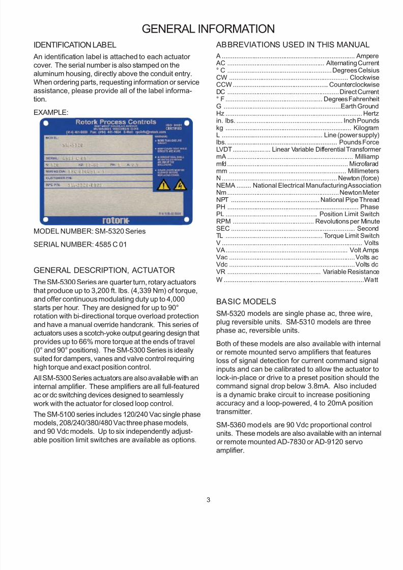
IDENTIFICATION LABEL
An identification label is attached to each actuator cover. The serial number is also stamped on thealuminum housing, directly above the conduit entry.When ordering parts, requesting information or serviceassistance, please provide all of the label informa-
tion.
EXAMPLE:
MODEL NUMBER: SM-5320 Series
SERIAL NUMBER: 4585 C 01
GENERAL DESCRIPTION, ACTUATOR
The SM-5300 Series are quarter turn, rotary actuatorsthat produce up to 3,200 ft. lbs. (4,339 Nm) of torque,
and offer continuous modulating duty up to 4,000starts per hour. They are designed for up to 90°rotation with bi-directional torque overload protection
and have a manual override handcrank. This series of actuators uses a scotch-yoke output gearing design thatprovides up to 66% more torque at the ends of travel(0° and 90° positions). The SM-5300 Series is ideallysuited for dampers, vanes and valve control requiringhigh torque and exact position control.
All SM-5300 Series actuators are also available with aninternal amplifier. These amplifiers are all full-featuredac or dc switching devices designed to seamlessly
work with the actuator for closed loop control.
The SM-5100 series includes 120/240 Vac single phasemodels, 208/240/380/480 Vac three phase models,and 90 Vdc models. Up to six independently adjust-able position limit switches are available as options.
GENERAL INFORMATION
ABBREVIATIONS USED IN THIS MANUAL
A .......................................................................... Amper AC ...................................................... Alternating Curren° C ..........................................................Degrees CelsiuCW .................................................................. ClockwisCCW..................................................... CounterclockwisDC ..............................................................Direct Curren
° F ...................................................... Degrees FahrenheG .................................................................Earth GrounHz ............................................................................ Hertin. lbs. ........................................................... Inch Poundkg ...................................................................... KilogramL ........................................................ Line (power supplylbs. ............................................................. Pounds ForcLVDT..................... Linear Variable Differential TransformemA ...................................................................... Milliammfd................................................................... Microfaramm ................................................................. MillimeterN................................................................ Newton (forceNEMA ........ National Electrical Manufacturing AssociatioNm..............................................................Newton Mete
NPT ................................................. National Pipe ThreaPH ......................................................................... PhasPL ................................................... Position Limit SwitcRPM ............................................. Revolutions per MinutSEC ..................................................................... SeconTL ...................................................... Torque Limit SwitcV .............................................................................. VoltVA.................................................................... Volt AmpVac ......................................................................Volts aVdc ......................................................................Volts dVR .................................................... Variable Resistanc
W ..............................................................................Wa
BASIC MODELS
SM-5320 models are single phase ac, three wire,plug reversible units. SM-5310 models are threephase ac, reversible units.
Both of these models are also available with internaor remote mounted servo amplifiers that featuresloss of signal detection for current command signainputs and can be calibrated to allow the actuator tolock-in-place or drive to a preset position should thecommand signal drop below 3.8mA. Also included
is a dynamic brake circuit to increase positioningaccuracy and a loop-powered, 4 to 20mA positiontransmitter.
SM-5360 models are 90 Vdc proportional controlunits. These models are also available with an internaor remote mounted AD-7830 or AD-9120 servoamplifier.

7/23/2019 pub051-001-00_0211
http://slidepdf.com/reader/full/pub051-001-000211 5/24
4
SM-5300 Series Specifications
Rotation: Up to 90°
Modulation Rate: AC: 2,000 starts/hour.Minimum position change of 1%
DC: 4,000 starts/hour.Minimum position change of 1%
Temperature: -40°F to 150°F (-40°C to 65°C).
Environment Ratings: NEMA Type 4 (IP65) or Explosion Proof, Class I, Division 1, Groups C& D.Class II, Division 1, Groups E, F & G.
Weight: Approximately 350 lbs. (158 kg).
Enclosure Materials: Cast aluminum alloy.
Lubrication Type: Grease, permanently lubricated.
Gearing: Spur type.
Hold on Loss of Power : Self-locking. Optional brakeallows improved positioning response.
Mounting: Any position.
Torque Limit ing: Bi-Directional, disables motor in
one direction when torque rating is exceeded.
Output Shaft: 2.69-2.695 in. (68.33-68.45 mm)diameter with 30 tooth spline.
Anti -Condensation Heater : 120 or 240 Vac, 30 Wattwith thermostat set for 110°F (43.3°C).
Position Feedback: 1000 ohm potentiometer.
Optional contactless feedback available.
Field Wiring: To barrier type terminal blocks.
Integral Thermal Protection/Single Phase AC
Motor : Standard thermal overload protection at130°C, self resetting.
End-of-Travel Position Limit Switches:20 amp, 250 Vac
Run Stall Inernal Remote
208/3/50-60 2.9 14.5
240/3/50-60 2.5 12.5
380/3/50 2.2 13.5
480/3/50-60 1.2 6.2
90 Vdc NA AD-7830 or
AD-9120
120/1/50-60
208/1/50-60
240/1/50-60
*Multipl y these shift times by 1.2 for 50 Hz operation of AC models. All travel times are nominal for 90° of movement.
Input Power
Volts/Phase/Hz
Current (Amps) Actuator
Model
Amplif ier Model *Time/Torque
sec./ft . lbs. (Nm)
12
6
AD-8130 AD-8230
23/1600 (2170)
47/1600 (2170)
47/3200 (4339)
23/1600 (2170)
47/1600 (2170)
47/3200 (4339)
SM-5360 9.5 N/A AD-7830
or
AD-9120
NA
SM-5310 AD-8900 AD-8900
23/1600 (2170)
47/1600 (2170)
47/3200 (4339)
SM-5320
240/1/50-60
120/1/50-60 10
5

7/23/2019 pub051-001-00_0211
http://slidepdf.com/reader/full/pub051-001-000211 6/24
5
Installation
MOUNTING
The outline and mounting dimensions for a standard unitare shown on page 23 of this manual. The rear cover
opposite output shaft must have clearance so that it maybe removed for adjustments and interconnect wiring.When the actuator is directly coupled to a drive shaft, itis recommended that a flexible no backlash type cou-pling be used. The output shaft is also available with asplined output for standard lever arms and linkage driveto the driven load. The unit may be mounted on the
standard foot mount, or a flange mount. Mounting maybe in any position convenient to the driven load.
When mounting the unit, be sure that no excessive axialor side loading is applied to the output shaft. The limit
switches and position feedback are connected throughgearing to the output shaft of the actuator which shouldbe positively secured to the driven load shaft so that noslippage can occur which would cause misalignment or damage.
When manual override is required, as in the event of apower failure, the crank is engaged by operating the auto-manual selector lever at the top of the actuator. The crankmay then be turned in the proper direction for the de-
sired output shaft rotation. If during manual operatioelectric power is applied to the actuator, the selector ver will return to the “auto” position and the actuator wrespond to the power command, The shift from “manu
to “auto” disengages the manual crank, which cannot power driven, thereby protecting the operator.
Care, however, should be taken when driving a loadrecognize that excessive output torque may be developby forcing the handcrank. A mechanical telltail-indica
shaft adjacent to the crank indicates over-torquing. Ttelltail-indicator shaft will either protrude or recede dpending on the direction of over-torquing. Discontincranking on over-torque warning.
The motor, limit switch and feedback area of the actuadepends upon the cover to maintain the NEMA 4 ratinThis cover should be removed only when actual workbeing done in that area and reinstalled immediately the
after.
This actuator contains no internal mechanical stops. is allowed to run outside of the initial factory alignmeof the limit switches, a realignment of switches and feeback might be required. However, no internal dama
will have occurred.
OPTION SPECIFICATIONS
Servo Amplif iers: All servo amplifiers include a field-adjustable command signal monitor that can be set for lock-in-place, or drive to a pre-set position if thecurrent command signal is lost. They also have adynamic brake circuit which helps increase position-ing accuracy of the loop by minimizing motor coast.These amplifiers are also equipped with a 4-20mA
isolated two wire, loop-powered transmitter.
Local Auto/Manual, INC/OFF/DEC Toggle Switches: Actuator-mounted switches for control of Auto/Manualand INCREASE/OFF/DECREASE. These are available astoggle switches or NEMA style rotary switches.
Output Shaft: 2.75 in. (69.85 mm) diameter with0.625 inch square (15.87 mm) keyway.
30 Tooth Splined Drive Arm: Reversible for ½ toothpositioning.
Linkage Kit: Includes two clevises, two adjustment
rods with lock nuts, two pipe adapters, two pins for clevises.
Auxiliary Posit ion Limi t Switches: (two or four): 20amps, 250 Vac maximum, or 5 amps at 28 Vdc.
Transmitter Position Feedback: 4 to 20mA, isolatedtwo wire loop-powered type. Tracks actuator position
Requires separate power.
Local Position Indicator : Reversible indicator to showopen or close in either direction.
Local Control: Actuator mounted NEMA 4 ratedswitches for control of AUTO/MANUAL andINCREASE/OFF/DECREASE. These are available as
toggle switches or NEMA-style rotary switches.
LVDT Contactless Feedback: Characterized feed-back assembly directly replaces the standard linear feedback potentiometer.

7/23/2019 pub051-001-00_0211
http://slidepdf.com/reader/full/pub051-001-000211 7/24
6
INSTALLATION WIRING
Typical wiring diagrams are shown on pages 7-8. Actual wir ing should fol low the print supplied withthe actuator .
The wiring diagram shows the fundamental connec-tions for the standard three-wire reversible single-phase motor, and the standard permanent magnet dcmotor. These units show an arrangement with torqueswitches, limit switches, feedback potentiometers, anda heater. To meet special requirements, certain items
shown may not be supplied. In all ins tances thewiring diagram appropriate to the equipment willbe supplied with each unit .
A barrier type terminal strip is located under the rear cover opposite the output shaft. Two conduit entriesare located in the side of the unit to accommodatestandard 1 inch N.P.T. and inch N.P.T. fittings.
CAUTION: On standard single-phase wiring, theposition limit switches and the torque switches arewired directly in the motor circui t and protect it at theextremes of travel or at torque cutout. Three phase ACor DC units must have these torque and position limit
switches wired into the controlling device to causeend of travel or torque shutdown. Care must be takenin wiring these to the controll ing device so that theappropriate direction of control is turned off whenthat direction’s l imit switch is actuated. If care is nottaken in phasing the equipment, damage may occur to
the actuator or driven load. Also, inductive devices,such as lights and solenoids, must not be paralleledacross motor terminals 1 and 2 or 1 and 3 as this will
upset the motor capacitor phase shift and motor torque will be lost.
• All wiring must be done in accordance with prevail-ing codes by qualified personnel.
• Fusing must be installed in line power, and should beof the slow blow type.
• Wiring should be routed to the actuator through the
two conduit openings. Generally, one conduit willcontain input power and earth ground wires. Theother conduit would then contain low level inputand output signal wiring. It is required that all lowlevel signal wiring be a shielded type with the shieldgrounded at source common.
• After installation, it is required that all conduits besealed to prevent water damage and to maintain
NEMA 4 enclosure and applicable dust ignitionratings.
ROTORK PROCESS CONTROLS SUPPLIED
(OPTIONAL) COUPLING (Field Installed)
Jordan Controls has designed a three piece “wedge-lock” coupling which can be adjusted to align thedriven device to the actuator output shaft with noconcern as to keyway alignment of the shaft on the
drive device in relation to the spline on the actuator output shaft.
ADJUSTMENT
1. Slide coupling (5) onto driven shaft.
2. Slide coupling cone (1) and cup (2) onto actuator shaft.
3. Mount actuator with the two shafts in line and theshaft ends about inch (3 mm) apart.
4. Turn the shaft of the driven device to the closeposition.
5. Run the actuator to the close limit switch.
6. Lock coupling (5) to the driven shaft by pinning or
other suitable method.
7. Slide cone (1) to fit flat in recess of coupling (5).
8. Install three bolts and lockwasher (3) and (4) andtighten. (20-30 ft. lbs.)
9. Operate the actuator in the open direction andback to the close direction until the close limit
switch stops the actuator.
10. If the driven shaft does not move to the exact close
position you want, loosen the three bolts and turnthe driven shaft. Tighten the bolts. (20-30 ft. lbs.)
NOTE: Keep the coupling parts clean whileassembling.
See page 21 of this manual for Jordan supplied linkagecomponents information.
Installation

7/23/2019 pub051-001-00_0211
http://slidepdf.com/reader/full/pub051-001-000211 8/24
7
Typical Wiring Diagrams
ACTUATOR WITHOUT AN INTERNAL AMPLIFIER
SM-5320 (120/240 Vac) SM-5360 (90 Vdc)
Notes: 1. The torque limit switches are factory set to trip if the rating of the actuator is exceeded.
2. Shielded wire is required for position feedback signal wiring.
SM-5310 SERIES ACTUATOR
Notes: 1. Optional remote three phase reversing starter shown.
2. Caution: Care must be taken in properly phasing position and torque limit
switches with respect to clockwise and counterclockwise positioning.
Due to wide variations
in terminal numbering
of actuator products, actual
wiring should follow the print
supplied with the actuator .
1 & 2 1 & 3 1(+ ) & 2(-) 1(-) & 2(+ )
Viewing Output Shaft CCW CW CW CCW
AC Power Applied to Terminals Actuator
Action
DC Power Applied to Terminals

7/23/2019 pub051-001-00_0211
http://slidepdf.com/reader/full/pub051-001-000211 9/24
8
Start Up
ACTUATORS WITHOUT SERVO AMPLIFIERS
A. POSITION LIMIT SWITCH ADJUSTMENT
(Ref. Fig. 1)
NOTE:
The actuator is shipped in its mid-travel position.
1. Referring to your wiring diagram, apply motor power anddrive the actuator in the CW output shaft direction
(looking at the shaft), until PL1 trips and stops the
actuator. This is the CW limit switch setting and starting
point for final switch adjustment.
2. Move the controlled equipment to the same starting
point and couple the actuator output shaft to the driven
shaft.
3. Apply motor power to rotate the output shaft CCW about
5 degrees, allowing PL1 switch to reset.
4. Apply motor power to rotate the output shaft CW until
PL1 trips, turning off the motor. If the driven device is notat the desired position:
a. Remove motor power.
b. Using an 1/8 inch, long shaft allen wrench,
loosen Cam Screw #1 about 1/4 turn.
c. Rotate Cam #1 CCW to allow the actuator to run
further in the CW direction or rotate the cam CW
to turn the actuator off sooner. (Cam #1 will turn
off the motor for CW output shaft rotation, when
the switch roller lever moves to the high side of
the cam with the cam rotating CW.)
d. Position the Cam as desired and while holding in
place, tighten screw #1 with moderate force to
adequately clamp the cam in place.
DO NOT OVER TIGHTEN.
5. Apply motor power to drive the actuator to the desired
CCW position or until PL2 trips and stops the motor. If
the driven device is not at the desired position:
a. Remove motor power.
b. Loosen Cam Screw #2 about a turn.
c. Rotate Cam #2 CW to increase the actuator’stotal travel range or CCW to decrease the travel
range.
d. Hold the cam in place and tighten screw #2.
6. Electrically operate the actuator to its CW limit and back
to the CCW limit to check switch settings. Readjust Cam
#1 or #2 as needed.
7. Switches 3 through 6 (optional) are adjusted by loosening
their respective cam screws and rotating the cam. They
may be set anywhere within the range of PL1 or PL2.
8. If the unit is equipped with a feedback device and
switches PL1 or PL2 were readjusted, proceed with the
proper feedback alignment prior to any further adjust-
ments or operation of the actuator.
B. POTENTIOMETER ADJUSTMENT
1. Run the actuator to the center of travel. Loosen the three
panhead screws, securing the potentiometer body, and
rotate it to its center (50%) of travel position. An ohmme-
ter will be required for this adjustment. Tighten the three
screws.
2. Run the actuator to the zero or minimum travel limit.With the actuator running, monitor the potentiometer
with an ohmmeter to ensure the potentiometer
deadband is not crossed.
3. If your system requires a low resistance starting point,
loosen the three screws and rotate the potentiometer
body for the required starting resistance. This is usually
20 to 50 ohms (measured from the potentiometer wiper
arm to the zero end of the potentiometer).
C. 4 to 20mA TRANSMITTER OPTION
ADJUSTMENT
The ST-4130 (1000 ohm-input, 4 to 20 mA output) two wire
transmitter modulates the current on a direct current supply
proportional to the input resistance. It is powered by a 12.0
to 36.0 Vdc regulated power supply line which is modulated
from 4 to 20 mA proportional to the resistance of the input.

7/23/2019 pub051-001-00_0211
http://slidepdf.com/reader/full/pub051-001-000211 10/24
9
For the unit to function optimally, the 4mA end of thefeedback potentiometer must be preset to 50 ohms.
1. Position the actuator to the desired 4mA setting.
2. With potentiometer resistance at 50 ohms, adjust ELEVA-TION for 4.0mA output.
3. Position the actuator to the desired 20mA setting.
4. Adjust RANGE for 20mA output.
5. Repeat steps 1 through 4 until desired accuracy isachieved.
6. To reverse the 4 and 20mA output, interchange the BLUEand YELLOW wires and return to step 1.
D. ACTUATOR WITH INTERNAL AD-8230
SERVO AMPLIFIER
Switch and feedback potentiometer alignment is accom-plished in the same manner as actuator without amplifiers,except motor power is supplied from the amplifier. Varyingthe command signal input to the amplifier will allow reversalof the rotation of the actuator output shaft to run to theminimum/maximum switch settings. If the actuator does notrun to the limit switch, but stops short, the amplifier hasnulled and adjustments of span, elevation, loss of signal, or feedback potentiometer may be required. Refer to IM-0607for information on the AD-8130 amplifier.
E. ACTUATOR WITH INTERNAL AD-7830 SERVO AMPLIFIER
Switch and feedback potentiometer alignment is accom-plished in the same manner as actuator without amplifiers,except motor power is supplied from the amplifier. Varyingthe command signal input to the amplifier will allow reversalof the rotation of the actuator output shaft to run to theminimum/maximum switch settings. If the actuator does notrun to the limit switch, but stops short, the amplifier hasnulled and adjustments of span, elevation, loss of signal, or feedback potentiometer may be required. Refer to IM-0606
for information on the AD-7830 amplifier.
F. ACTUATOR WITH INTERNAL AD-7830
SERVO AMPLIFIER
Switch and feedback potentiometer alignment is accom-plished in the same manner as actuator without amplifiers,except motor power is supplied from the amplifier. Varyingthe command signal input to the amplifier will allow reversaof the rotation of the actuator output shaft to run to theminimum/maximum switch settings. If the actuator does norun to the limit switch, but stops short, the amplifier has
nulled and adjustments of span, elevation, loss of signal, or feedback potentiometer may be required. Refer to IM-0620for information on the AD-8900 amplifier.
G. ACTUATOR WITH INTERNAL AD-9120
SERVO AMPLIFIER
Switch and feedback potentiometer alignment is accom-plished in the same manner as actuator without amplifiers,except motor power is supplied from the amplifier. Varyingthe command signal input to the amplifier will allow reversaof the rotation of the actuator output shaft to run to the
minimum/maximum switch settings. If the actuator does norun to the limit switch, but stops short, the amplifier hasnulled and adjustments of span, elevation, loss of signal, or feedback potentiometer may be required. Refer to IM-0626for information on the AD-9120 amplifier.
H. CHARACTERIZED CAM ADJUSTMENT
(OPTION)
The characterized feedback assembly is an option whichdirectly replaces the standard linear feedback potentiomete
Prior to adjusting the cam, the end of travel limit switchmust be set and the proper cam installed for your particlar system requirements on the characterized cam shaftFour different cams are supplied with each characterizedassembly. The cams are printed on both sides and may flipped over to reverse the characterization action inrelation to the output shaft rotation.
The cams are each printed with a letter “O”, “F”, or “B”which indicate the cam type. Three of the cams are shapedto correspond to X=2, 1, and 0.5 respectively in the equa-tion:
% amplifier input = (% shaft rotation)x

7/23/2019 pub051-001-00_0211
http://slidepdf.com/reader/full/pub051-001-000211 11/24
10
The fourth cam is used for any value of x between 0.5 and 2and must be cut by the user. For details on cutting this cam,see “To Shape Feedback Cam”.
a. Run the actuator to the zero or minimum position limit.While running, observe the direction of character camrotation.
b. Is the cam rotating in the direction of 100-0 for your system requirement? If not, remove the thumb screw andflip the cam over. Tighten the screw.
c. Have you selected the proper cam for the system require-ment? If not, remove the thumb screw and change thecam, installing the cam the same as in (b) above. (Greenor Black side up.)
d. Loosen three screws and remove the cam assembly.
e. Rotate the cam until the zero on the cam is in line withthe center line of the potentiometer or LVDT shaft.
f. Potentiometers need no further adjustment.
g. LVDT contactless feedback may require fine zeroing.
i. Apply power to the LVDT and monitor the outputwith a volt meter.
ii. Loosen the two body clamp screws and slide thebody of the LVDT to obtain zero output.
iii. Tighten the body clamp screws.
iv. If a finer adjustment is desired, loosen the nut onthe LVDT shaft and turn the shaft slightly oneway or the other and tighten the nut.
TO SHAPE FEEDBACK CAM
With characterized feedback, one of the four cams supplied(cam B), is partially shaped. For installation, it must be cut toits final shape by the user. This cam is used if none of theother three cams produces the desired input-output relation-ship where:
% amplifier input = (% shaft position)X
Two typical conditions where the user might want to use thefourth cam are:
1.In equation above, if the value of X is not equal to 0.5 or 2.
2.In equation, if the value of X is equal to 0.5 or 2, and if
upper shaft position is not equal to 100% (90°), and/or lower shaft position is not equal to 5% (0°).
To lay out the cam shape for the desired input-outputrelationship, it is necessary to determine outputs (rise incam), for various inputs (amount of cam rotation). The rise inthe cam corresponds to % of maximum output range and theamount of cam rotation corresponds to % input signal toamplifier.
1. Lay out on graph paper, axes and maximum and minimumslopes as shown in figure 2. (Maximum slope is 25 unitsrise per 10% shaft rotation; minimum slope is 5 units per 10% rotation.)
Figure 1
2. If either upper or lower shaft position is not at 0 or 100%(0° or 90°) respectively, lay out additional x-axis scale asshown in figure 3 on page 13. Use both sets of valueswhen plotting cam shape in step 3.
3. Calculate outputs (rise in cam) for 5% or 10% incrementsin input for entire input scan (actual cam rotation). NOTE:only output values that fall within maximum and mini-mum slope lines can be used.
4. Plot these values on cam. Scribe smooth line between
points and grind cam to this shape.Refer to example for typical cam calculations and layout.
TYPICAL FEEDBACK CAM CALCULATIONS
EXAMPLE: Assume X in (input/output equation) = 0.5, and
that upper and lower shaft positions are at 100% and 20%
(90° and 18°), same as center illustration of Figure 3.
Input
0 20% 0
10 28 1*
20 36 4*
30 44 9*
40 52 16
50 60 25
60 68 36
70 76 49
80 84 64
90 92 81
100 100 100
Output
% of actual
rotation
location
on cam
% rise
on cam
Note: These values fall outside of minimum slope on graph.

7/23/2019 pub051-001-00_0211
http://slidepdf.com/reader/full/pub051-001-000211 12/24
11
Figure 3
Figure 2

7/23/2019 pub051-001-00_0211
http://slidepdf.com/reader/full/pub051-001-000211 13/24
12
Troubleshooting Guide
TROUBLE POSSIBLE CAUSE REMEDY
a. No power to actuator a. Check source, fuses, wiring
b. Motor overheated and internal
thermal switch tripped (single phase AC
motors only)
b. Let motor cool and determine why
overheating occurred (such as,
excessive duty cycle or ambient
temperature)
c. Motor burned outc. Replace motor and determine cause
of failure
d. Motor drag brake improperly adjusted d. Adjust as detailed on page 20
e. Motor drag brake defective e. Replace drag brake
f. Both end of travel switches open or
one open and one defective
f. Adjust switch settings or replace
defective switch
g. Actuator output shaft stalledg. Check drive load for mechanical jam
and correct cause
h. Defective motor run capacitor h. Replace capacitor (AC models)
i. Load exceeds actuator torque ratingi. Reduce load or replace actuator with
one with appropriate torque rating
j. Power applied to CW & CCW
rotation at same time j. Correct power input problem
k. Amplifier defective k. Replace amplifier
l. Amplifier is in Loss of Signall. Check command signal to verify signal
greater than 3.8 mA is present
m. Amplifier deadband is too wide m. Reduce deadband setting
a. Power applied to CW & CCW
rotation at the same timea. Correct power input problem
b. Damaged power gearing b. Repair gearing
c. Defective motor run capacitor c. Replace capacitor
d. Motor drag brake d. Adjust or replace as required
Motor runs, output shaft does not rotate a. Defective power gearing a. Repair gearing
a. Switch wired wrong or is defective a. Correct w iring or replace switch
b. Motor phased incorrectly b. Correct wiring
a. Motor drag brake improperly adjusted a. Adjust as detailed on page 20
b. Motor drag brake defective b. Replace drag brake
a. Power still on a. Remove power
b. Load is jammed and motor drag
brake slipsb. Remove jammed load
c. Drag brake missing or improperly
adjusted.c. Replace drag brake
Handcrank does not move
output shaft
Motor does not operate
Motor hums but does not run
Motor does not shut off at limit switch
Actuator backdrives when power is
removed

7/23/2019 pub051-001-00_0211
http://slidepdf.com/reader/full/pub051-001-000211 14/24
13
Troubleshooting Guide
a. Power not applied for other
directiona. Correct power problem
b. Power always applied to one
direction and electrically stalls when
applied for opposite direction
b. Correct power problem
c. Open limit switch for other
direction
c. Adjust or replace limit switch as
required
d. Actuator is torqued out d. Determine obstruct ion and correct
e. Motor has an open winding e. Replace motor
f. Motor and feedback potentiometer
are out of phasef. Reverse potentiometer end leads
g. Amplifier is defective g. Replace amplifier
a. Amplifier deadband is too wide a. Reduce deadband setting
b. Amplifier is defective b. Replace amplifier
c. Excessive noise on command signal
c. Reduce noise. Also ensure that
command signal wiring is shielded
with shield grounded at source
common only.
d. Defective feedback potentiometer d. Replace potentiometer
a. Amplifier deadband is too narrow a. Increase deadband setting
b. Amplifier is defective b. Replace amplifier
c. Excessive noise on command signal
c. Reduce noise. Also ensure that
command signal wiring is shielded
with shield grounded at source
common only.
a. Pot not aligned with end of travel
extremes and is being driven through
dead region
a. Align pot to range of actuator
b. Pot signal is erratic or nonexistent b. Replace pot
a. Defective pot a. Replace pot
b. Feedback gear not turning pot shaftb. Check gearing engagement and set
screw in gear hub
Pot signal is reversed for output shaft
rotationa. Pot is wired wrong
a. Reverse wiring from ends of pot at
actuator terminal block
a. Wiring to actuator incorrect a. Correct f ield wiring
b. Wiring from motor to terminals or
switches is reversedb. Correct internal actuator wiring
a. External wiring error a. Refer to IM-0607
b. Power supply fault b. Refer to IM-0607
c. Shunt resistance too light c. Refer to IM-0607
Motor runs, but only one way
Pot feedback signal not always present
during actuator rotation
Poor response to command signal
changes
4-20 mA customer feedback missing
or non-linear
Output shaft rotates wrong direction
for CW and CCW input power
Pot signal does not change as actuator
operates
Actuator oscillates at setpoint

7/23/2019 pub051-001-00_0211
http://slidepdf.com/reader/full/pub051-001-000211 15/24
14
Parts Identification

7/23/2019 pub051-001-00_0211
http://slidepdf.com/reader/full/pub051-001-000211 16/24

7/23/2019 pub051-001-00_0211
http://slidepdf.com/reader/full/pub051-001-000211 17/24
16
Handcrank Assembly
Screw Thrust Housing Assembly
Clutch Assembly
1 Hand Crank ........................................... 60B-014514-001
1 Hand Crank (Painted) ........................... 60B-014514-002
2 Handle ..................................................74A-014614-001
3 Screw, Hex. Hd. 3/8-16 x 1.50 Lg........ 54A-015081-150
4 Manual Override Shaft .........................61A-013950-001
5 Ret. Ring - #5160-150.........................58B-014186-150
6 Thrust Race ........................................... 17A-013949-0017 Needle Thrust Bearing .........................17A-013948-001
8 “O” Ring, 1.50 I.D. x 1.75 O.D. ..........74B-010957-222
9 Cap Assembly ....................................... 68A-015364-001
9 Cap Assembly (Painted) ........................ 68A-015364-002
10 Shear Pin (Single Shear) .......................61A-014553-001
11 Bushing ................................................. 18B-SP1988-065
1 Screw Thrust Housing ..................................... 60C-014508-0011 Screw Thrust Housing W/Hole .......................60C-014508-002
2 Bellville Washer ............................................. 56B-010462-006
2 Bellville Washer ............................................. 56B-010462-005
3 Spacer ............................................................. 61A-011778-001
3 Spacer ............................................................. 61A-011778-002
3 Spacer ............................................................. 61A-011778-003
3 Spacer ............................................................. 61A-011778-004
4 Roller Bearing Cone (Steep Angle)................17B-014239-001
5 Roller Bearing Cup (Steep Angle) ..................17B-014239-002
6 Spacer ............................................................. 61A-012516-001
7 Ret. Ring Truarc #N5000-362 .......................58B-014184-362
8 Thrust Sleeve ..................................................61A-011799-001
9 Bushing, .878 I.D. x 1.003 O.D. x 750 Lg. .... 18B-003814-019
10 “O” Rings 4-3/8 I.D. x 4-5/8 O.D. ................. 74B-010957-245
3 Spacer ............................................................. 61A-011778-007
3 Spacer ............................................................. 61A-011778-00911 Bushing ........................................................... 18B-003814-016
12 5/16-18 Setscrew x 3.8 Lg.............................. 54A-015077-038
3 Spacer ............................................................. 61A-011778-008
8 Thrust Sleeve ..................................................61A-011799-002
9 Bushing ........................................................... 61A-016668-001
1 Clutch Shaft................................................ 62A-013940-001
2 Ret. Ring 5100-50 .....................................58B-014183-050
3 Key, .125 Sq. x 2.87 Lg. S.S. #303 ............ 61A-014885-001
4 Clutch Disc ................................................ 61A-013941-001
5 Friction Disc (See Note) ............................ 61A-013942-001
6 Clutch Gear, 62T-20P-20E P.A. (36 Sec.) ... 16A-013943-0016 Clutch Gear, 49T-20P-20E P.A. (18 Sec.) ... 16A-013943-002
7 Gear Idler Drum........................................ 61A-013944-001
8 Clutch Drum .............................................. 61A-013945-001
9 Clutch Pinion ............................................. 16A-013946-001
10 1” x 2” MD Spring .....................................20A-012340-001
11 Lockwasher ................................................ 74A-014545-002
12 Bearing ...................................................... 17B-003813-025
13 Ret. Ring 5100-37 .....................................58B-014183-037
19 Thrust Washer............................................56B-004107-011
20 Bearing (Ref.) .............................................17B-003813-011
21 Ret. Ring (Ref.) 5000-112 ......................... 58B-014184-112
22 Ball Bearing ............................................... 17B-003813-031
23 Throwout Slider.........................................61A-010932-001
25 Locknut ...................................................... 74A-014545-001

7/23/2019 pub051-001-00_0211
http://slidepdf.com/reader/full/pub051-001-000211 18/24
17
Clutch Yoke Assembly
1 Clutch Yoke ...........................................60C-013958-0012 Dowel Pin, .250 x 1.00 Lg. .................. 57A-015226-1003 Spring ....................................................20A-012337-0014 Latch Pin ...............................................61A-011664-0015 Clevis Pin ..............................................75A-014771-0016 Cotter Pin, 3/32 Dia. X 1/2 Lg. .............7 Manual Crank Latch ..............................61A-013960-0018 Yoke Shaft .............................................62A-013961-00110 Roll Pin 1/4 Dia x 1” Lg. ......................57A-015215-100
Torque Limit Switch Assembly1 Switch Actuating Arm Assembly ...........68B-013573-0012 1/4-20 x 1” Lg. Soc. Hd. Cap. Scr. ........54A-015060-1003 1/4-20 Jam Nut .....................................55A-015069-0014 Limit Switch ..........................................46A-010016-0014 Limit Switch (Hi Pressure) ....................46A-010016-0035 Spacer Block .........................................61A-014626-0016 #6-32 x 1.38 Lg. Rd. Hd. Screw .......... 54A-015023-1387 #6 Lockwasher .....................................56A-015180-0028 Arm & Shaft Assembly .......................... 68A-014015-001
9 Bushing .................................................18B-SP1988-01510 Lever .....................................................61A-014007-00111 Button ...................................................61A-014552-00113 Sliding Shaft Assembly ..........................68A-014554-00114 .125 Dia. X .75 Lg. Roll Pin .................. 57A-015185-07515 .188 Dia. X 1-1/4” Lg. Dowel Pin ........57A-015206-12516 Gasket ...................................................13A-013928-00117 Sleeve Bearing ......................................18B-003814-03018 Ret. Ring-Truarc 5100-31.....................58B-014183-03119 Spring....................................................20A-013616-00120 Plain Washer, 5/16” ..............................56A-015222-00121 Insulator ................................................75A-003958-00122 Anti-Rotation Block ..............................61A-015655-00123 Retainer ................................................61A-017082-00124 Screw, Rd. Hd. #6-32 x .38 Lg. ........... 54A-015023-038
Drive Shaft Assembly
1 Nut Carrier ...........................................60B-013985-0012 Ret. Ring 5000-237 ..............................58B-014184-2373 Drive Nut ..............................................61A-014432-0014 Key, .250 Sq. x 3.00 Lg. ........................61B-010954-4965 Nut Spacer ............................................61A-013986-0017 Output Shaft (Position Tran.) Splined ... 62A-016731-0017 Output Shaft-splined ............................62B-013983-0017 Output Shaft-Key .................................. 62B-013984-0018 Pivot Arm ..............................................60B-014446-00110 Dowel Pin, .500 Dia. x 2.00 Lg. ........... 57A-015266-20012 Bearing .................................................61A-014540-00113 Spacer ...................................................13A-014541-00114 Bearing Retainer .................................. 61A-014542-00115 1/4-20 x 1/2 Lg. Rd. Hd. Screw ............54A-015063-05016 1/4 Lockwasher ..................................... 56A-015210-002

7/23/2019 pub051-001-00_0211
http://slidepdf.com/reader/full/pub051-001-000211 19/24
18
Standard Feedback - Potentiometers
Limit Switch Assembly
1 Precision One Turn, 1K ........................34B-003956-0432 Disc, Adapter (Precision) ......................61A-SM3304-0033 Screw, Truss Hd., 8-32 x 0.25 Lg. ........54A-015032-025

7/23/2019 pub051-001-00_0211
http://slidepdf.com/reader/full/pub051-001-000211 20/24
19
LUBRICATION
Under normal service conditions the motor, gearing,bearings, and parts are all pre-lubricated and shouldnot require periodic maintenance. If for any reason theunit is disassembled in the field, all oilite bushingsshould be resaturated with an SAE-10, non-detergent
oil and all gearing heavily coated with Amoco RykonPremium Grease #2 or equivalent grease. Care should
be taken to ensure that no foreign material is allowedto become combined with the grease in the gear train,which will cause premature failure. Keep gearboxclean and dry.
DRAG BRAKE ADJUSTMENT
The drag brake serves two functions: a) to prevent
actuator from backdriving at maximum rated torque;
and b) to allow the motor shaft to slip whenhandcranking and the output shaft load is in excess of rated torque.
The drag brake was factory set and should not needreadjustment. If it does need adjustment:
1. Apply an overhung load, equal to the maximumtorque rating to the output shaft.
2. Loosen drag brake jam nut until the motor shaftstarts to backdrive.
3. Tighten the drag brake jam nut just enough to
prevent backdriving.
4. While handcranking against the load, increase theload until motor backdriving occurs.
Maintenance
TORQUE LIMIT SWITCH ALIGNMENT
The torque limit switches are factory set and fieldadjustment is not advised unless proper test equip-ment is available. If adjustment must be done, use the
following procedure:1. Load the output shaft with a known load which
matches the torque rating of the actuator in anopposing direction for the switch being adjusted.
2. Apply power to the motor and run the actuator todrive the opposing load.
3. Increase the load by 5% to 10% and adjust the sescrew (140C) to trip the torque switch.
4. Remove the 5% to 10% increase of load and theswitch should reset.
5. Load the actuator in the opposite direction and sethe other switch in the same manner.
NOTE: When looking at the torque limit switchassembly as it is mounted in the actuator, the switchon the top of the assembly controls the CW torqueand the switch on the bottom controls the CCWtorque. The torque should be set near equal for bot
directions.
When the actuator is driven into a torque conditionin the CW direction (looking at the output shaft), thhandcrank handle will move slightly outward. For CCW direction the handle will pul l slight ly inward.

7/23/2019 pub051-001-00_0211
http://slidepdf.com/reader/full/pub051-001-000211 21/24
20
MOTOR REPLACEMENT
1. Disconnect all power to the actuator.
2. Remove screws, washers and rear cover.
3. Disconnect actuator output shaft from driven
device and remove actuator from mount.4. Remove bolts, washers, and front gear case cover.
Note location of all gearing.
5. Remove motor pinion.
6. Remove brake assembly from top of motor.
7. Disconnect motor wires - note colors.
8. Remove motor.
9. Reverse the procedure to install new motor. (Cleanand regrease all gearing, check bushings and
bearings, lubricate bushings with SAE-10, non-detergent oil.)
10. Reinstall the actuator.
POWER GEARING REPLACEMENT
1. Perform steps 1,3 & 4 of Motor Replacement.
2. Remove defective gear(s) and replace with new.
3. Ensure all gearing and oilite bushings are properly
lubricated as detailed above.4. Install front cover and Reinstall actuator.
POSITION LIMIT SWITCH REPLACEMENT
1. Disconnect all power to the actuator.
2. Remove rear cover.
3. Remove two screws and washers from appropriateswitch on assembly.
4. Install new switch and transfer wires from oldswitch one at a time.
5. No realignment should be necessary.
FEEDBACK POTENTIOMETER REPLACEMENT
A. One Turn Linear Potentiometer
1. Disconnect all power to the actuator.
2. Remove screws, washers, and rear cover.
3. Remove three screws holding potentiometer anddisc to housing.
4. Pull potentiometer and disc out of housing.
5. Measure location of gear from mounting disc tofarthest face of gear and note measurement.
6. Loosen set screws and remove gear.
7. Remove nut and washer holding potentiometer todisc.
8. Cut shaft of new potentiometer to same length as
old.
9. Mount new potentiometer on disc, tighten potenti-ometer nut, install gear to measured dimensionfrom step 5.
10. Install assembly in housing and tighten screws.
11. Using a 25 watt solder iron, remove wires from oldpotentiometer one at a time and solder to corre-sponding terminals on new potentiometer.
12. Align potentiometer and install cover.
B. Characterized Potentiometer
1. Disconnect power and remove rear cover.
2. Remove three screws and pull potentiometer off of pins.
3. Install new potentiometer and tighten screws.
4. Using a 25 watt solder iron, remove wires from old
potentiometer one at a time and solder to corre-sponding terminals on new potentiometer.CAUTION - DO NOT USE EXCESSIVE HEAT
WHEN SOLDERING.5. Align potentiometer and install cover.
C. LVDT Assembly Replacement
1. Same as Characterized Potentiometer replacementabove.
2. Align LVDT body for zero output (see alignmentprocedure, characterized cam adjustment on page12, step G).
Maintenance

7/23/2019 pub051-001-00_0211
http://slidepdf.com/reader/full/pub051-001-000211 22/24
21
Major Dimensions
These dimensions are subject to change without notice and should not be used for preparation of drawings or fabrication of
installation mounting. Current installation dimension drawings are available on request.

7/23/2019 pub051-001-00_0211
http://slidepdf.com/reader/full/pub051-001-000211 23/24
22
SM-5000 SERIES DRIVE ARM AND LINKAGE OPTIONS
Notes:
1. Maximum total linkage length is specified to prevent
buckling under compressive load.
2. Adjustable drive arms are also available to allow “A”
length to vary from 6 to 10 inches (152 to 254 mm). In
this case, the adapter-clevis has rod ball ends with
lubricating fittings.
3. Special drive arm lengths are available to meetapplication requirements.
“ A” LENGTH
in. (mm)
(See Note 3)
“ B” LENGTH
ft. (m)
“ C” LENGTH
in. (mm)
“ D” LENGTH
in. (mm)
“ E” LENGTH
in. (mm)
“ F” DIA. HOLE
min.-max.
in. (mm)
“ G” PIPE SIZE
10 (254) 18 (5.5) 10 (254) 12.25 (311) 17 (432)0.75 - 1.5
(19 - 38.1)1 - 1/4 (NPT)
The dimensions in this manual are subject to change without notice
and should not be used for preparation of drawings or fabrication
of installation mounting. Current installation dimension drawings
are available upon request.
Rotork Process Controls
5607 West Douglas Avenue
Milwaukee, Wisconsin 53218
Phone: (414) 461-9200
FAX: (414) 461-1024
E-Mail: [email protected]
IM-0462 2/1/2011

7/23/2019 pub051-001-00_0211
http://slidepdf.com/reader/full/pub051-001-000211 24/24
www.rotork.com
A full listing of our worldwide sales andservice network is available on our website.
Electric Actuators and Control Systems
Fluid Power Actuators and Control Systems
Gearboxes and Gear Operators
Projects, Services and Retrofit
UK
Rotork plc
tel +44 (0)1225 733200
fax +44 (0)1225 333467
email [email protected]
USA
Rotork Process Controls
tel +1 (414) 461 9200
fax +1 (414) 461 1024
email [email protected]