PTP 650 LPU and Grounding Kit Installation Guide
16
Cambium PTP 650 LPU and Grounding Kit Installation Guide
Transcript of PTP 650 LPU and Grounding Kit Installation Guide
Cambium PTP 650 LPU and Grounding Kit Installation Guide
Accuracy
While reasonable efforts have been made to assure the accuracy of this document, Cambium Networks assumes no liability resulting from any inaccuracies or omissions in this document, or from use of the information obtained herein. Cambium Networks reserves the right to make changes to any products described herein to improve reliability, function, or design, and reserves the right to revise this document and to make changes from time to time in content hereof with no obligation to notify any person of revisions or changes. Cambium Networks does not assume any liability arising out of the application or use of any product, software, or circuit described herein; neither does it convey license under its patent rights or the rights of others. It is possible that this publication may contain references to, or information about Cambium Networks products (machines and programs), programming, or services that are not announced in your country. Such references or information must not be construed to mean that Cambium Networks intends to announce such Cambium Networks products, programming, or services in your country.
Copyrights
This document, Cambium Networks products, and 3rd Party software products described in this document may include or describe copyrighted Cambium Networks and other 3rd Party supplied computer programs stored in semiconductor memories or other media. Laws in the United States and other countries preserve for Cambium Networks, its licensors, and other 3rd Party supplied software certain exclusive rights for copyrighted material, including the exclusive right to copy, reproduce in any form, distribute and make derivative works of the copyrighted material. Accordingly, any copyrighted material of Cambium Networks, its licensors, or the 3rd Party software supplied material contained in the Cambium Networks products described in this document may not be copied, reproduced, reverse engineered, distributed, merged or modified in any manner without the express written permission of Cambium Networks. Furthermore, the purchase of Cambium Networks products shall not be deemed to grant either directly or by implication, estoppel, or otherwise, any license under the copyrights, patents or patent applications of Cambium Networks or other 3rd Party supplied software, except for the normal non-exclusive, royalty free license to use that arises by operation of law in the sale of a product.
Restrictions
Software and documentation are copyrighted materials. Making unauthorized copies is prohibited by law. No part of the software or documentation may be reproduced, transmitted, transcribed, stored in a retrieval system, or translated into any language or computer language, in any form or by any means, without prior written permission of Cambium Networks.
License Agreements
The software described in this document is the property of Cambium Networks and its licensors. It is furnished by express license agreement only and may be used only in accordance with the terms of such an agreement.
High Risk Materials
Cambium and its supplier(s) specifically disclaim any express or implied warranty of fitness for any high risk activities or uses of its products including, but not limited to, the operation of nuclear facilities, aircraft navigation or aircraft communication systems, air traffic control, life support, or weapons systems (“High Risk Use”). Any High Risk is unauthorized, is made at your own risk and you shall be responsible for any and all losses, damage or claims arising out of any High Risk Use.

Page 1
About this guide
This guide describes how to install the PTP 650 LPU and Grounding Kit (Cambium part number C000065L007). This kit contains two lightning protection units (LPUs) and LPU ground cables. One kit is used for each of the PSU and AUX copper Cat5e Ethernet interfaces to the ODU. Users of this guide will require expertise in outdoor radio equipment installation.
Note
This guide assumes that the LPUs are being installed on a PSU drop cable. To understand how procedures differ when installing an AUX drop cable, refer to the PTP 650 Series User Guide.
Note
PTP 650 LPUs are not suitable for installation on SFP copper Cat5e Ethernet interfaces. For SFP drop cables, obtain suitable surge protectors from a specialist supplier.
Related documents For full PTP 650 installation instructions, refer to the PTP 650 Series User Guide.
Version information Document number and version: phn-3348_002v000.
Date of publication: July 2013.
Waste Electrical and Electronic Equipment (WEEE) For instructions on waste disposal of used products, refer to http://www.cambiumnetworks.com/support

Page 2
Components and tools
LPU and grounding kit (Cambium part number C000065L007) This kit contains the following components:
Lightning protection units (LPUs) LPU grounding point nuts and washers
ODU to top LPU drop cable (600 mm) EMC strain relief cable glands
U-bolts, nuts and washers for mounting LPUs
ODU to top LPU ground cable (M6 lugs at both ends), bolt and washers
Bottom LPU ground cable (M6 and M10 lugs)
ODU to grounding system ground cable (M6 and M10 lugs), bolt and washers

Page 3
Warning
The LPU contains insulation tape fitted to the top of the printed circuit board. Do not remove this tape, as hazardous voltages are present within the unit.
Note
If LPUs are being installed, use only the five EMC cable glands supplied in the LPU and grounding kit (with black caps). Discard the non-EMC cable glands supplied in the ODU kits (with silver caps), as these may only be used in PTP 650 installations without LPUs.
Note
Ensure that the LPUs and ODU are connected using the correct Cat5e cable and connectors, as described below.
Outdoor Cat5e cable (drop cable) For copper Cat5e connections from the ODU to the PSU, LPUs and other devices, use Cat5e cable that is gel-filled and shielded with copper-plated steel, for example Superior Essex type BBDGe. This is known as “drop cable”.
Caution
Always use Cat5e cable that is gel-filled and shielded with copper-plated steel. Alternative types of drop cable are not supported by Cambium Networks.
Order Superior Essex type BBDGe cable from Cambium Networks in 330 m (1000 ft) or 100 m (328 ft) lengths:
Cambium description Cambium part number
1000 ft Reel Outdoor Copper Clad CAT5E WB3175
328 ft (100 m) Reel Outdoor Copper Clad CAT5E WB3176
Other lengths of this cable are available from Superior Essex.
Page 4
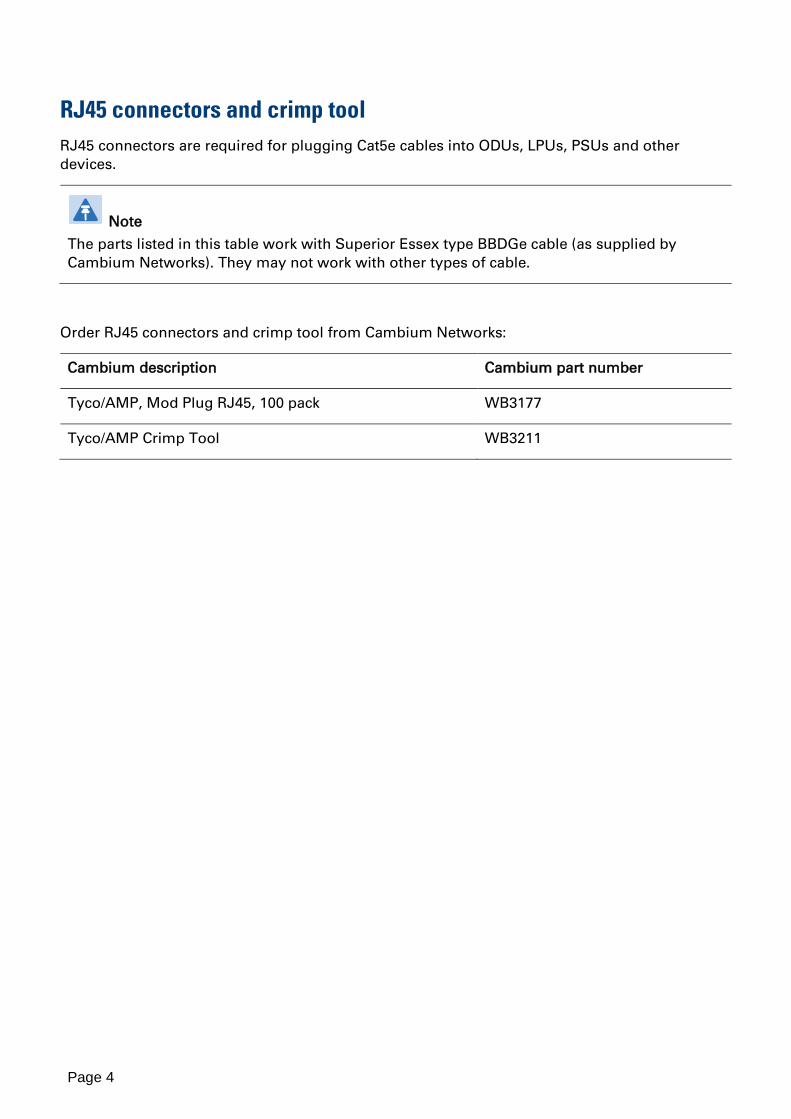
RJ45 connectors and crimp tool RJ45 connectors are required for plugging Cat5e cables into ODUs, LPUs, PSUs and other devices.
Note
The parts listed in this table work with Superior Essex type BBDGe cable (as supplied by Cambium Networks). They may not work with other types of cable.
Order RJ45 connectors and crimp tool from Cambium Networks:
Cambium description Cambium part number
Tyco/AMP, Mod Plug RJ45, 100 pack WB3177
Tyco/AMP Crimp Tool WB3211

Page 5
Typical deployment
A PTP 650 site typically consists of a high supporting structure such as a mast, tower or building for the outdoor equipment (ODU and optional external antenna); and an equipment building or moisture-proof enclosure for the indoor equipment (PSU).
In the basic configuration, there is only one Ethernet interface, a copper Cat5e connection from the ODU (PSU port) to the PSU and network terminating equipment, as shown here:
In more advanced configurations, there may be up to three copper Cat5e Ethernet interfaces to the ODU (PSU, SFP and AUX). The PSU and AUX interfaces each require one PTP 650 LPU and Grounding Kit (Cambium part number C000065L007). PTP 650 LPUs are not suitable for installation on SFP interfaces.

Page 6
Drop cable preparation
Main drop cable and LPU-PSU drop cable 1 Cut two lengths of drop cable: one from top LPU to bottom LPU and one from bottom
LPU to PSU.
2 Thread two glands over the main drop cable (one at each end). Thread one gland over the LPU-PSU drop cable (at LPU end only). Do not tighten the gland nuts:
3 At the LPU ends of these cables, strip the cable ends and fit RJ45 connector load bars:
4 At the LPU ends of these cables, fit the RJ45 connector housings as shown. To ensure there is effective strain relief, locate the cable inner sheath under the connector housing tang:
The PTP 650 Series User Guide describes how to prepare the PSU end of the drop cable.
Page 7
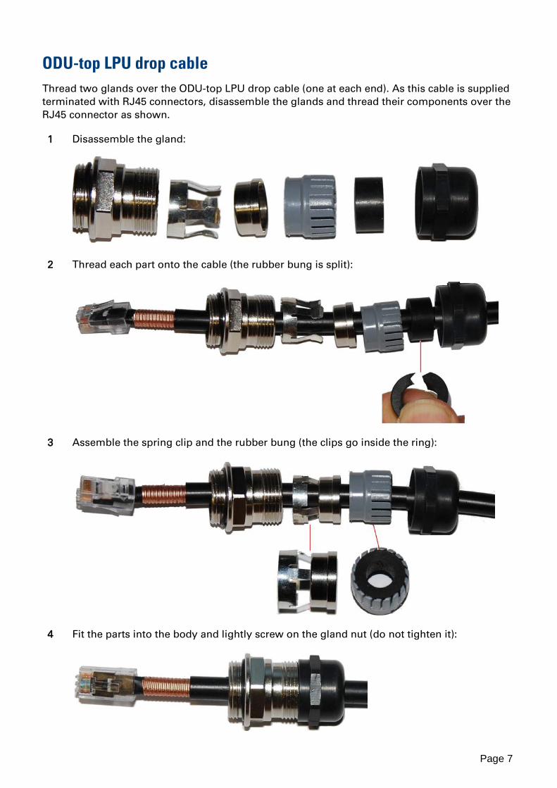
ODU-top LPU drop cable Thread two glands over the ODU-top LPU drop cable (one at each end). As this cable is supplied terminated with RJ45 connectors, disassemble the glands and thread their components over the RJ45 connector as shown.
1 Disassemble the gland:
2 Thread each part onto the cable (the rubber bung is split):
3 Assemble the spring clip and the rubber bung (the clips go inside the ring):
4 Fit the parts into the body and lightly screw on the gland nut (do not tighten it):

Page 8
Installing and grounding the LPUs
Top LPU 1 Select the preferred mounting option - back-to-back or separate:
2 Mount the ODU and top LPU, ensuring that the LPU is vertical with cable glands facing downwards. Tighten both ODU bracket bolts to a torque of 14 Nm (11 lb ft).
3 Connect the ODU (PSU port) to the top LPU (either port) using the 600 mm drop cable supplied in the LPU kit, following the procedure in Connecting drop cables to the LPU and ODU.
4 Connect the top LPU (other port) to the main drop cable, following the procedure in Connecting drop cables to the LPU and ODU. Fasten the two drop cables such that they are not coiled together and do not cross each other.

Page 9
5 Fasten one ground cable to each ODU grounding point using the M6 (small) lugs: one is for the top LPU (M6 lug at other end) and the other is for the tower or building (M10 lug at other end). It does not matter which cable goes on which grounding point. Tighten both grounding bolts to a torque of 5 Nm (3.9 lb ft):
M6 lug M6 lug
M6 lug to top LPU
M10 lug to ground
Bolt Toothed washer M6 lug Toothed washer

Page 10
6 Fasten one ground cable to the top LPU using the M6 (small) lug. Tighten both nuts to a torque of 5 Nm (3.9 lb ft):
Locking nut Washer M6 lug Washer Nut Toothed washer
M6 lug to ODU
7 Select a tower or building grounding point within 0.3 meters (1 ft) of the ODU bracket on the same metal. Remove paint from the surface and apply anti-oxidant compound. Fasten the ODU grounding cable to this point using the M10 (large) lug.
8 If local regulations mandate the independent grounding of all devices, add a third ground cable to connect the top LPU directly to the grounding system:

Page 11
Bottom LPU 1 Select a mounting point for the bottom LPU within 600 mm (24 in) of the building entry
point. Mount the LPU vertically with cable glands facing downwards:
2 Connect the two drop cables into the RJ45 ports of the bottom LPU, following the procedure in Connecting drop cables to the LPU and ODU.
3 Fasten one ground cable to the bottom LPU using the M6 (small) lug. Tighten both nuts to a torque of 5 Nm (3.9 lb ft):
Locking nut Washer M6 lug Washer Nut Toothed washer
M10 lug to ground
4 Select a building grounding point near the LPU bracket and on the same metal. Remove paint from the surface and apply anti-oxidant compound. Fasten the LPU ground cable to this point using the M10 (large) lug.

Page 12
Connecting drop cables to the LPU and ODU (LPU illustrated)
1 Plug the RJ45 connector into the socket in the unit, ensuring that it snaps home. Fit the gland body to the RJ45 port and tighten it to a torque of 5.5 Nm (4.3 lb ft):
2 Fit the gland nut and tighten until the rubber seal closes on the cable. Do not over-tighten the gland nut, as there is a risk of damage to its internal components:
Correct
Incorrect

Page 13
Test resistance in the drop cable
Before connecting the bottom end of the copper Cat5e drop cable to the PSU or network terminating equipment, connect it to a cable tester and test that the resistances between pins are within the correct limits. If any of the tests fail, examine the drop cable for wiring faults.
Order the PTP drop cable tester from the support website (http://www.cambiumnetworks.com/support) by completing the order form.
Perform the following resistance tests on PSU and AUX drop cables:
Measure the resistance between…
Enter measured resistance
To pass test, resistance must be…
Circle “Pass” or “Fail”
Additional tests
Pins 1 and 2 Ohms
<20 Ohms (60 Ohms) (*2)
Pass Fail
These resistances must be within 10% of each other (*1). Circle “Pass” or “Fail”:
Pass Fail
Pins 3 and 6 Ohms
<20 Ohms (60 Ohms) (*2)
Pass Fail
Pins 4 and 5 Ohms
<20 Ohms (60 Ohms) (*2)
Pass Fail
Pins 7 and 8 Ohms
<20 Ohms (60 Ohms) (*2)
Pass Fail
Pin 1 and screen (ODU ground)
K Ohms
>100K Ohms (*3)
Pass Fail
Pin 8 and screen (ODU ground)
K Ohms
>100K Ohms (*3)
Pass Fail
(*1) Ensure that these resistances are within 10% of each other by multiplying the lowest resistance by 1.1 – if any of the other resistances are greater than this, the test has failed.
(*2) A resistance of 20 Ohms is the maximum allowed when the cable is carrying Ethernet. A resistance of 60 Ohms is the maximum allowed when the cable is carrying only power to the ODU (when Ethernet is carried by one of the other ODU interfaces).
(*3) This limit applies regardless of cable length.
www.cambiumnetworks.com
Cambium Networks and the stylized circular logo are trademarks of Cambium Networks, Ltd. All other trademarks are the property of their respective owners.
© Copyright 2013 Cambium Networks, Ltd. All rights reserved.
Cambium Networks
Cambium Networks provides professional grade fixed wireless broadband and microwave solutions for customers around the world. Our solutions are deployed in thousands of networks in over 153 countries, with our innovative technologies providing reliable, secure, cost-effective connectivity that’s easy to deploy and proven to deliver outstanding metrics.
Our award-winning Point to Point (PTP) radio solutions operate in licensed, unlicensed and defined use frequency bands including specific FIPS 140-2 solutions for the U.S. Federal market. Ruggedized for 99.999% availability, our PTP solutions have an impeccable track record for delivering reliable high-speed backhaul connectivity even in the most challenging non-line-of-sight RF environments.
Our flexible Point-to-Multipoint (PMP) solutions operate in the licensed, unlicensed and federal frequency bands, providing reliable, secure, cost effective access networks. With more than three million modules deployed in networks around the world, our PMP access network solutions prove themselves day-in and day-out in residential access, leased line replacement, video surveillance and smart grid infrastructure applications.
Cambium Networks solutions are proven, respected leaders in the wireless broadband industry. We design, deploy and deliver innovative data, voice and video connectivity solutions that enable and ensure the communications of life, empowering personal, commercial and community growth virtually everywhere in the world.
Support website: http://www.cambiumnetworks.com/support
Main website: http://www.cambiumnetworks.com
Sales enquiries: [email protected]
Support enquiries: [email protected]
Telephone number list: http://www.cambiumnetworks.com/contact
Address: Cambium Networks Limited, Linhay Business Park, Eastern Road, Ashburton, Devon, UK, TQ13 7UP