PTO Dance...PTO Dance Post Valentine Day Dance February 20, 2019

PTO Manufacturing Engineering
PTS02-083ME, Controls Specification Attachment 3 - Hydraulic Data Form 2631
Revision Date: November 14, 2013 Revision Number: 4.2
Controls Specification
PTO Manufacturing Engineering Administrator: Core Controls (Warren Schwanky) Revision Date: NOVEMBER 14, 2013
Attachment 3 - Hydraulic Data Form 2631
Document Number: PTS02-083ME
DO NOT SUBSTITUTE WITHOUT WRITTEN APPROVAL (DEVIATION) FROM FORD CONTROLS ENGINEER, SUPPLIER AND CORE ENGINEERING ADMINISTRATOR. Sources listed in random order.
Copyright @ Ford Motor Co. 2013 Revision Number: 4.2 Retention Period: S+1
Page 2 of 46
Controls Specification
PTO Manufacturing Engineering Administrator: Core Controls (Warren Schwanky) Revision Date: NOVEMBER 14, 2013
Attachment 3 - Hydraulic Data Form 2631
Document Number: PTS02-083ME
1 ACCUMULATOR ................................................................................................................................ 6
1.1 BLADDER TYPE-REQUIRES CONTROLS ENGINEER APPROVAL ........................................ 6 1.2 PISTON TYPE-PREFERRED .................................................................................................... 6 1.3 ACCUMULATOR SAFETY BLOCK ............................................................................................ 6 1.4 FUSE & FUSE ADAPTER .......................................................................................................... 6 1.5 PRESSURE CUT-OFF VALVE, PILOT OPERATED .................................................................. 6
2 CYLINDER ......................................................................................................................................... 7 2.1 CYLINDER ................................................................................................................................. 7 2.2 CYLINDER WITH ROD LOCKING ............................................................................................. 7 2.3 ROTATING TYPE ...................................................................................................................... 7 2.4 GUIDED ..................................................................................................................................... 7
3 DIAGNOSTIC ..................................................................................................................................... 7 3.1 TEST PORT ADAPTER ............................................................................................................. 7 3.2 TEST PORT GAUGE ADAPTER ............................................................................................... 8 3.3 TEST PORT HOSE KIT ............................................................................................................. 8
4 DRIVE COUPLING ............................................................................................................................. 8 4.1 DRIVE COUPLING .................................................................................................................... 8
5 FILTER ............................................................................................................................................... 8 5.1 ELEMENTS – HYDRAULIC ....................................................................................................... 8 5.2 PRESSURE & RETURN LINE FILTER HOUSING – HYDRAULIC ............................................ 9 5.3 OFFLINE OR AUXILIARY FILTRATION .................................................................................. 10
6 FLANGE ........................................................................................................................................... 10 6.1 FLANGE ISO 61/62 TYPE 1 .................................................................................................... 10
7 FLOW CONTROLS .......................................................................................................................... 10 7.1 INLINE – NON COMPENSATED ............................................................................................. 10 7.2 SANDWICH – NON COMPENSATED ..................................................................................... 10 7.3 SUBPLATE MOUNTED – NON COMPENSATED ................................................................... 10 7.4 IN-LINE PRESSURE & TEMPERATURE COMPENSATED .................................................... 11 7.5 SANDWICH – PRESSURE COMPENSATED .......................................................................... 11 7.6 SUBPLATE MOUNTED PRESSURE & TEMPERATURE COMPENSATED ............................ 11
8 FLUID TYPE ..................................................................................................................................... 11 8.1 FLUID TYPE ............................................................................................................................ 11
9 GAUGE ............................................................................................................................................ 11 9.1 GAUGE .................................................................................................................................... 11 9.2 ADAPTORS ............................................................................................................................. 12 9.3 GAUGE ISOLATOR & GAUGE PANEL ................................................................................... 12
10 HEAT EXCHANGER, PROCESS WATER CHILLER ..................................................................... 12 10.1 AIR/OIL .................................................................................................................................. 12 10.2 SHELL AND TUBE OR PLATE TYPE (WATER-OIL) ............................................................. 12 10.3 HEATER – IN TANK DESIGN ................................................................................................ 12 10.4 PROCESS WATER CHILLER................................................................................................ 13
11 HOSE ............................................................................................................................................. 13 11.1 HOSE ..................................................................................................................................... 13
Copyright @ Ford Motor Co. 2013 Revision Number: 4.2 Retention Period: S+1
Page 3 of 46

Controls Specification
PTO Manufacturing Engineering Administrator: Core Controls (Warren Schwanky) Revision Date: NOVEMBER 14, 2013
Attachment 3 - Hydraulic Data Form 2631
Document Number: PTS02-083ME
11.2 HOSE – THERMOPLASTIC ................................................................................................... 13 11.3 FITTINGS .............................................................................................................................. 13 11.4 GUARDS AND SLEEVES ...................................................................................................... 13 11.5 CLAMPS ................................................................................................................................ 14 11.6 HOSE WHIP RESTRAINT CABLE ASSEMBLY ..................................................................... 14
12 MANIFOLD – BAR TYPE (207 BAR/3000 PSI) .............................................................................. 14 12.1 MANIFOLD – ALUMINUM OR STEEL ................................................................................... 14
13 MOTOR .......................................................................................................................................... 14 13.1 GEAR ..................................................................................................................................... 14 13.2 GEROTOR ............................................................................................................................. 14 13.3 AXIAL PISTON TYPE ............................................................................................................ 14 13.4 RADIAL PISTON TYPE ......................................................................................................... 15
14 PUMP ............................................................................................................................................. 15 14.1 GEAR – EXTERNAL AND INTERNAL ................................................................................... 15 14.2 PISTON – AXIAL ................................................................................................................... 15 14.3 ROTARY SCREW .................................................................................................................. 15 14.4 VANE TYPE ........................................................................................................................... 15
15 QUICK DISCONNECTS ................................................................................................................. 15 15.1 HYDRAULIC .......................................................................................................................... 15
16 RESERVOIR................................................................................................................................... 16 16.1 BREATHER ........................................................................................................................... 16 16.2 FLUID LEVEL WITH DIAL THERMOMETER ......................................................................... 16
17 ROTARY ACTUATOR .................................................................................................................... 16 17.1 RACK AND PINION TYPE ..................................................................................................... 16 17.2 VANE TYPE ........................................................................................................................... 16
18 SHOCK ABSORBER...................................................................................................................... 16 18.1 SHOCK ABSORBER ............................................................................................................. 16
19 SURGE SUPPRESSOR ................................................................................................................. 17 19.1 SURGE SUPPRESSOR (PULSATION DAMPER) ................................................................. 17
20 SWITCHES ..................................................................................................................................... 17 20.1 LEVEL .................................................................................................................................... 17 20.2 PRESSURE ........................................................................................................................... 17 20.3 TEMPERATURE .................................................................................................................... 17
21 TUBE .............................................................................................................................................. 17 21.1 FITTINGS .............................................................................................................................. 17 21.2 SUPPORTS ........................................................................................................................... 17 21.3 TUBING STEEL ..................................................................................................................... 18 21.4 TUBING SWIVELS – HYDRAULIC INLINE & 90º .................................................................. 18
22 VALVE ............................................................................................................................................ 18 22.1 BALL – HIGH PRESSURE (207 BAR AND GREATER) ......................................................... 18 22.2 BALL – LOW PRESSURE (30 BAR) ...................................................................................... 18 22.3 CARTRIDGE – STANDARD CAVITY ..................................................................................... 19 22.4 CARTRIDGE – 2-WAY DIRECTIONAL .................................................................................. 19 22.5 CARTRIDGE – 3-WAY & 4-WAY DIRECTIONAL .................................................................. 19
Copyright @ Ford Motor Co. 2013 Revision Number: 4.2 Retention Period: S+1
Page 4 of 46

Controls Specification
PTO Manufacturing Engineering Administrator: Core Controls (Warren Schwanky) Revision Date: NOVEMBER 14, 2013
Attachment 3 - Hydraulic Data Form 2631
Document Number: PTS02-083ME
22.6 DIN CARTRIDGE POPPET (DIN 24342) NG16 & NG25 ....................................................... 19 22.7 CARTRIDGE – CHECK VALVE ............................................................................................. 20 22.8 CARTRIDGE – FLOW CONTROL ......................................................................................... 20 22.9 CARTRIDGE – NEEDLE VALVE ........................................................................................... 21 22.10 CARTRIDGE – PRESSURE REDUCING VALVE ................................................................ 21 22.11 CARTRIDGE – RELIEF VALVE ........................................................................................... 21 22.12 CARTRIDGE – SEQUENCE VALVE .................................................................................... 21 22.13 CHECK – INLINE ................................................................................................................. 21 22.14 CHECK – SANDWICH (MODULAR) .................................................................................... 21 22.15 CHECK – SUBPLATE MOUNTED ....................................................................................... 22 22.16 DIRECTIONAL VALVE CETOP 3 (DO3) – NG6 .................................................................. 22 22.17 DIRECTIONAL VALVE CETOP 5 (DO5) – NG10 ................................................................ 22 22.18 DIRECTIONAL VALVE CETOP 8 (DO8) – NG22 & NG25 ................................................... 23 22.19 PRESSURE CONTROL IN-LINE MOUNTED ....................................................................... 23 22.20 PRESSURE CONTROL SANDWICH (MODULAR) .............................................................. 23 22.21 PRESSURE CONTROL VALVES (SUBPLATE) .................................................................. 24 22.22 PRESSURE REDUCING SUBPLATE .................................................................................. 24 22.23 PRESSURE REDUCING SANDWICH (MODULAR) ............................................................ 24
23 PROPORTIONAL VALVES ............................................................................................................ 25 23.1 PROPORTIONAL DIRECTIONAL SERVO SOLENOID TYPE: MINIMUM FILTRATION ISO 18/16/13 ......................................................................................................................................... 25 23.2 PROPORTIONAL DIRECTIONAL : MINIMUM FILTRATION ISO 18/16/13 ........................... 25 23.3 PROPORTIONAL PRESSURE CONTROLS: MINIMUM FILTRATION ISO 18/16/13 ............ 25
24 SERVO ........................................................................................................................................... 25 24.1 SERVO .................................................................................................................................. 25
25 DIGITAL CONTROLLERS ............................................................................................................. 26 25.1 CONTROLLER ...................................................................................................................... 26
26 APPENDIX 1- BOSCH-REXROTH POWER UNITS ....................................................................... 27 27 APPENDIX 2- PARKER POWER UNITS ........................................................................................ 36
27.1 PARKER POWER UNITS – LESS THAN 230 L (60 GAL.) .................................................... 36 27.2 PARKER POWER UNITS – GREATER THAN 230 L (60 GAL.) ............................................ 40
28 RECORD OF CHANGES AND AMENDMENTS ............................................................................. 44
Copyright @ Ford Motor Co. 2013 Revision Number: 4.2 Retention Period: S+1
Page 5 of 46

Controls Specification
PTO Manufacturing Engineering Administrator: Core Controls (Warren Schwanky) Revision Date: NOVEMBER 14, 2013
Attachment 3 - Hydraulic Data Form 2631
Document Number: PTS02-083ME
1 Accumulator 1.1 Bladder type-Requires Controls engineer approval Manufacturers Model numbers Parker BA***B3R01-AS1 (S= Specify country(s) for
Certification) 1.2 Piston type-Preferred Manufacturers Model numbers Parker A6E****SL2KRF (S= Specify country(s) for
Certification) 1.3 Accumulator safety block Manufacturers Model numbers Bosch-Rexroth ABZSS***E***SO104 (lockable, CE approved) Parker SBAR**E1T1-***-TL (lockable, CE approved)
1.4 Fuse & fuse adapter Manufacturers Model numbers Parker 087471**** (fuse, specify disc pressure at 40% over
system pressure) Parker 870760 (fuse adapter with #5 SAE port). These
items are included with ordering code in piston accumulators.
1.5 Pressure cut-off valve, pilot operated Manufacturers Model numbers Bosch-Rexroth DA6V series Parker SBAR**E1T1-100AA1 (EU Cert.)
Copyright @ Ford Motor Co. 2013 Revision Number: 4.2 Retention Period: S+1
Page 6 of 46

Controls Specification
PTO Manufacturing Engineering Administrator: Core Controls (Warren Schwanky) Revision Date: NOVEMBER 14, 2013
Attachment 3 - Hydraulic Data Form 2631
Document Number: PTS02-083ME
2 Cylinder 2.1 Cylinder Manufacturers Model numbers Parker HMIRS (ISO6020-2) w/ BSPP threaded ports Bosch-Rexroth CDT3..F/CGT3..F1(160 bar) w/ BSPP ports
CDT3..F/CGT3..Z2 (210 bar) w/ BSPP ports 2.2 Cylinder with Rod Locking Manufacturers Model numbers Bosch-Rexroth CDT3..F/CGT3..F1 (160 bar) w/ BSPP ports
CDT3..F/CGT3..Z2 (210 bar) w/ BSPP ports With Sitema rod locking device and G threaded ports. Available on 40 mm through 80 mm bore only. (min release 30-60 bar/435-870 psi depending on bore)
Parker HMI with KFH rod locking device and R threaded ports. Available on 40 mm through 80 mm bore only. (min release 30 to 60 bar depending on bore). ISO60020-2
2.3 Rotating type Manufacturers Model numbers Buck Logansport Model 801 (no internal checks) Buck Logansport Model 802 (with internal checks)
2.4 Guided Manufacturers Model numbers Parker HBN, HBC, HBT, HBR, HBB series (52 bar/750 psi)
BSPP threads 3 Diagnostic 3.1 Test port adapter Manufacturers Model numbers Stauff SMK20 G1/4 VC Parker EMA3/1/4ED BSPP threads
Copyright @ Ford Motor Co. 2013 Revision Number: 4.2 Retention Period: S+1
Page 7 of 46

Controls Specification
PTO Manufacturing Engineering Administrator: Core Controls (Warren Schwanky) Revision Date: NOVEMBER 14, 2013
Attachment 3 - Hydraulic Data Form 2631
Document Number: PTS02-083ME
3.2 Test port gauge adapter Manufacturers Model numbers Parker MAV 1/4NPT-MA3-KM (use with flexible hose kit) Parker MAVMD 1/4NPT-MA3 (gauge direct connect)
3.3 Test port hose kit Manufacturers Model numbers Parker SMA3**** (200 mm, 400 mm, 800 mm, 2000 mm,
4000 mm lengths) 4 Drive coupling 4.1 Drive coupling Manufacturers Model numbers Lovejoy (steel type) KTR (Steel Type)
5 Filter 5.1 Elements – Hydraulic Manufacturers Model numbers Parker PTO-HF series (10 micron) Bosch-Rexroth Elements to DIN 24550
Copyright @ Ford Motor Co. 2013 Revision Number: 4.2 Retention Period: S+1
Page 8 of 46

Controls Specification
PTO Manufacturing Engineering Administrator: Core Controls (Warren Schwanky) Revision Date: NOVEMBER 14, 2013
Attachment 3 - Hydraulic Data Form 2631
Document Number: PTS02-083ME
5.2 Pressure & return line filter housing – Hydraulic Manufacturers Model numbers Parker PTO series HF2, HF3, HF4 (PRESSURE LINE)
(HF2) HF15P*L/H**E5MD50***19V (2” ELEMENT for up to 80L/Min) (HF3) HF31P3H**E5MD50***11V (3” ELEMENT for up to 310L/Min) (HF4) HF50P4*L/H**E5MD50***1V (4” ELEMENT for up to 500L/Min) Use L-elements for systems with pressure up to 207BAR/3000PSI HF2-HF4 include visual and electrical indicators
Parker PTO series HF2, HF3, HF4 (RETURN LINE) (HF2) 15CN*L**E5MD25***19V (2” ELEMENT) (HF3) 40CN2L**E5MD25***19V (3” ELEMENT) (HF4) IL4*L**E5MD25***V (4” ELEMENT) HF2-HF4 include visual and electrical indicators
Bosch-Rexroth 10TEN0063-H10XLA00V2.2-M-R4 (return filter, Din, max flow 60L/Min) Replacement element R928005855, Required the electrical indicator WE-2SP-M12X1
Bosch-Rexroth 10TEN0100-H10XLA00V2.2-M-R4 (return filter, Din, max flow 70L/Min) Replacement element R928005873, Required the electrical indicator WE-2SP-M12X1
Bosch-Rexroth 245LEN0063H10XLB00-V5.0-M-R4 (pressure filter, Din, max flow 30L/Min) Replacement element R928006701, Required the electrical indicator WE-2SP-M12X1
Bosch-Rexroth 245LEN0100H10XLB00-V5.0-M-R4 (pressure filter, Din, max flow 70L/Min) Replacement element R928006701, Required the electrical indicator WE-2SP-M12X1
Bosch-Rexroth 245LEN0160H10XLB00-V5.0-M-R4 (pressure filter, Din, max flow 190L/Min) Replacement element R928006809, Required the electrical indicator WE-2SP-M12X1
Copyright @ Ford Motor Co. 2013 Revision Number: 4.2 Retention Period: S+1
Page 9 of 46

Controls Specification
PTO Manufacturing Engineering Administrator: Core Controls (Warren Schwanky) Revision Date: NOVEMBER 14, 2013
Attachment 3 - Hydraulic Data Form 2631
Document Number: PTS02-083ME
5.3 Offline or auxiliary filtration Manufacturers Model numbers Parker PTO series “S”, Model DC3-*ON1*SE5MD*GU
6 Flange 6.1 Flange ISO 61/62 type 1 Manufacturers Model numbers Parker Code 61
5151HK SAE with English bolts M1M1HK ISO, DIN with metric bolts
(preferred) Code 62
HFHFHK SAE with English bolts M2M2HK ISO, DIN with metric bolts
(preferred) 7 Flow controls 7.1 Inline – Non compensated Manufacturers Model numbers Bosch-Rexroth MK*G1X / V MG*G1X / V Parker 9F flow control or 9N & 9MV needle valve.
Colorflow series BSPP ported. 7.2 Sandwich – Non compensated Manufacturers Model numbers Bosch-Rexroth Z2FSK, Z2FS Parker Stack module: ZRD Series
7.3 Subplate mounted – Non compensated Manufacturers Model numbers Bosch-Rexroth F6ZP Parker FS series
Copyright @ Ford Motor Co. 2013 Revision Number: 4.2 Retention Period: S+1
Page 10 of 46

Controls Specification
PTO Manufacturing Engineering Administrator: Core Controls (Warren Schwanky) Revision Date: NOVEMBER 14, 2013
Attachment 3 - Hydraulic Data Form 2631
Document Number: PTS02-083ME
7.4 In-Line pressure & temperature compensated Manufacturers Model numbers Parker PCCMS series
7.5 Sandwich – Pressure compensated Manufacturers Model numbers Bosch-Rexroth Z2FRM (pressure and temperature compensated) Parker FA, FC Series w/BD03 Body
7.6 Subplate mounted pressure & temperature compensated Manufacturers Model numbers Bosch-Rexroth 2FRM10 & 16; 2FRM6 Parker FG3PK, 2F1C series
8 Fluid type 8.1 Fluid type Manufacturers Model numbers Mobil For assembly and MQL machines DTE25/ISO 46
(Ford Tox # 016567) Houghton For wet machining with Houghton Vegetable oil
based cutting fluids- Cosmolubric TR 46/ISO 46 (Ford Tox #180695)
BP Castrol For wet machining with BP-Castrol Vegetable oil based cutting fluids-Carelube HES 46/ISO 46 (Ford Tox #178832)
Current transmission Fluid Program dependant Transmission oil 9 Gauge 9.1 Gauge Manufacturers Model numbers Parker PGB series (bottom mount, ISO 228-1 “G” thread) Parker PGC series (center back mount, ISO 228-1 “G”
thread) Wika Type 213.53 Bosch-Rexroth ABZM M363 (See Data Sheet RE50205)
Copyright @ Ford Motor Co. 2013 Revision Number: 4.2 Retention Period: S+1
Page 11 of 46

Controls Specification
PTO Manufacturing Engineering Administrator: Core Controls (Warren Schwanky) Revision Date: NOVEMBER 14, 2013
Attachment 3 - Hydraulic Data Form 2631
Document Number: PTS02-083ME
9.2 Adaptors Manufacturers Model numbers Parker MAV, MAVE, F40H, PTR34 Bosch-Rexroth R9011564xx (¼”, ½” metric to BSPP)
9.3 Gauge isolator & gauge panel Manufacturers Model numbers Bosch-Rexroth AF6EA4X/*** Bosch-Rexroth MS2A2X/*** Parker Gauge isolation valve
Single station: 9GT412S series, dual range bar & psi, ISO 1179-1 ports
Parker Panel mounted gauge and selector valve Multiple station: 9MSGI **** series, dual range bar & psi, ISO 1179-1 ports
10 Heat exchanger, Process water chiller 10.1 Air/oil Shall be approved by Ford Controls Engineering. Manufacturers Model numbers Young Radiator Thermal Transfer
10.2 Shell and tube or plate type (water-oil) Shall be approved by Ford Controls Engineering. Manufacturers Model numbers Young Radiator Thermal transfer co Parker OAW series Funke
10.3 Heater – In tank design Manufacturers Model numbers Cromalox Watlow
Copyright @ Ford Motor Co. 2013 Revision Number: 4.2 Retention Period: S+1
Page 12 of 46

Controls Specification
PTO Manufacturing Engineering Administrator: Core Controls (Warren Schwanky) Revision Date: NOVEMBER 14, 2013
Attachment 3 - Hydraulic Data Form 2631
Document Number: PTS02-083ME
10.4 Process water chiller Ford models are globally available. Manufacturers Model numbers Parker PCW020AT3P3FMX-FMC (18,910 Btu/H) Parker PCW040AT3P3FMX-FMC (37,882 Btu/H) Parker PCW060AT3P3FMX-FMC (60,989 Btu/H) Parker PCW080AT3P3FMX-FMC (78,783 Btu/H) Parker PCW0A130T3P3FMX-FMC (128,006 Btu/H)
11 Hose 11.1 Hose Manufacturers Model numbers Parker 422 global hose: SAE 100R1 type AT, ISO 1436/I Parker 302/301 global hose: SAE 100R2 type AT, ISO
1436/II Parker 482TC for Cat Track applications SAE 100R1, ISO
1436/I 11.2 Hose – Thermoplastic Manufacturers Model numbers Parker 540N (SAE100R7) with 55 series crimp fittings
(hose assemblies shall utilize crimp type fittings to ISO 12151-1)
11.3 Fittings Manufacturers Model numbers Parker 43 series crimp style connections to ISO 12151-1
(E02 Bite type Chrome 6 Free) Parker 48 series crimp style connections to ISO 12151-1
(E02 Bite type Chrome 6 Free) 11.4 Guards and sleeves Manufacturers Model numbers Parker Protection shields: HP, HT and HP-B series Parker Hose guards: PolyGuard, ParKoil, and Partek nylon
sleeve
Copyright @ Ford Motor Co. 2013 Revision Number: 4.2 Retention Period: S+1
Page 13 of 46

Controls Specification
PTO Manufacturing Engineering Administrator: Core Controls (Warren Schwanky) Revision Date: NOVEMBER 14, 2013
Attachment 3 - Hydraulic Data Form 2631
Document Number: PTS02-083ME
11.5 Clamps Manufacturers Model numbers Parker “CL” hose clamps or ParKlamp/ParKlamp kits for
hose 11.6 Hose whip restraint cable assembly Manufacturers Model numbers Parker WRA*** (for hose fittings or adapters) Parker WRF*** (for code 61 and 62 flanges) Bosch-Rexroth ABZH Series
12 Manifold – Bar type (207 BAR/3000 PSI) 12.1 Manifold – Aluminum or steel Manufacturers Model numbers Bosch-Rexroth ABM/HSR series BSPP ports (aluminum, 307
bar/3000 psi) Bosch-Rexroth ABM/HSR series BSPP ports (ductile iron, 345
bar/5000 psi) Parker
Damon (to purchase direct) MSP**(NG6, NG10 & NG25) (rear ported, ISO 1179-1, BSPP threaded ports
13 Motor 13.1 Gear Consult Ford Controls Engineering for approval. Manufacturers Model numbers Bosch-Rexroth Series AZM F & AZM N (external) Parker PGM & M2 Series
13.2 Gerotor Consult Ford Controls Engineering for approval. Manufacturers Model numbers Parker TE, TF, TH & 110A series
13.3 Axial Piston type Consult Ford Controls Engineering for approval. Manufacturers Model numbers Bosch-Rexroth A10VFM, A2FM Parker F11, F12 series
Copyright @ Ford Motor Co. 2013 Revision Number: 4.2 Retention Period: S+1
Page 14 of 46

Controls Specification
PTO Manufacturing Engineering Administrator: Core Controls (Warren Schwanky) Revision Date: NOVEMBER 14, 2013
Attachment 3 - Hydraulic Data Form 2631
Document Number: PTS02-083ME
13.4 Radial piston type Consult Ford Controls Engineering for approval. Manufacturers Model numbers Bosch-Rexroth MCR 03 05,10,15,20 (radial piston type) Parker MR, MRE series
14 Pump 14.1 Gear – External and internal Manufacturers Model numbers Bosch-Rexroth AZP F, AZP N,& AZP G (external) Bosch-Rexroth PGF, & PGH (internal) Parker PGG2 (internal) Gerotor Parker PGP (external)
14.2 Piston – Axial Manufacturers Model numbers Bosch-Rexroth A10VSO, A4VS0 Parker ISO PD (up to 140 cc) low noise
ISO PV Plus (up to 270 cc) low noise 14.3 Rotary screw Manufacturers Model numbers I.M.O.
14.4 Vane type Manufacturers Model numbers Bosch-Rexroth PVV, PV7 (fixed and press. Compensated) Parker T6, T67, T7 & PVS series
15 Quick disconnects 15.1 Hydraulic Refer to Ford PTO quick disconnect matrix on program eMIX for proper coupler selection. Manufacturers Model numbers Parker FF and 60 series
Copyright @ Ford Motor Co. 2013 Revision Number: 4.2 Retention Period: S+1
Page 15 of 46

Controls Specification
PTO Manufacturing Engineering Administrator: Core Controls (Warren Schwanky) Revision Date: NOVEMBER 14, 2013
Attachment 3 - Hydraulic Data Form 2631
Document Number: PTS02-083ME
16 Reservoir 16.1 Breather Manufacturers Model numbers Parker AB*G1***MI (PTO AB series w/10 micron nominal
air rating element & vacuum indicator)
Bosch-Rexroth BE7SL** (w/10 micron nominal air rating element & vacuum indicator)
Bosch-Rexroth TLF series (w/10micron replacement element H10XL
16.2 Fluid level with dial thermometer Manufacturers Model numbers Lube Devices For visual monitoring only with removable
temperature indicator Bosch-Rexroth AB31-21
17 Rotary actuator 17.1 Rack and pinion type Manufacturers Model numbers Parker LTR and HTR & M series
17.2 Vane type Manufacturers Model numbers Parker HRN series
18 Shock absorber 18.1 Shock absorber Manufacturers Model numbers Parker SC and MC self-compensating metric mounting
Copyright @ Ford Motor Co. 2013 Revision Number: 4.2 Retention Period: S+1
Page 16 of 46

Controls Specification
PTO Manufacturing Engineering Administrator: Core Controls (Warren Schwanky) Revision Date: NOVEMBER 14, 2013
Attachment 3 - Hydraulic Data Form 2631
Document Number: PTS02-083ME
19 Surge suppressor 19.1 Surge suppressor (Pulsation Damper) Shall be approved by Ford Controls Engineering) Manufacturers Model numbers Parker PT series, flange mount Bosch-Rexroth SYPD Series
20 Switches 20.1 Level Manufacturers Model numbers Refer to Electrical Data Form 2630
20.2 Pressure Manufacturers Model numbers Refer to Electrical Data Form 2630
20.3 Temperature Manufacturers Model numbers Refer to Electrical Data Form 2630
21 Tube 21.1 Fittings Shall utilize ISO 1179-1 (ISO 228-1 port threads) male studs and ISO 8434-1 tube
connection. Tube connection shall be pre-set utilizing the Parker Hyferset process. Manufacturers Model numbers Parker E02 metric tube fitting w/ BSPP thread bite type
Chrome 6 Free 21.2 Supports Manufacturers Model numbers Parker ParKlamp RAP series (metric tube clamps)
Copyright @ Ford Motor Co. 2013 Revision Number: 4.2 Retention Period: S+1
Page 17 of 46

Controls Specification
PTO Manufacturing Engineering Administrator: Core Controls (Warren Schwanky) Revision Date: NOVEMBER 14, 2013
Attachment 3 - Hydraulic Data Form 2631
Document Number: PTS02-083ME
21.3 Tubing steel All tubing shall be metric seamless according to ISO 10673 and ISO 3304, Chrome 6 Free.
DO NOT PAINT! See the table below for detail sizes
Tube OD mm Wall Thickness Pressure Rating
(bar) Pressure Rating
(psi)
4 1 502 7279 6 1 374 5423 8 1 289 4191 10 1 249 3611 12 1.5 305 4423 15 1.5 249 3611 18 1.5 210 3045 20 2 249 3611 22 2 228 3306 28 2.5 224 3248
Manufacturers Model Numbers 21.4 Tubing swivels – Hydraulic inline & 90º Manufacturers Model numbers Parker DVGE & DG series
22 Valve 22.1 Ball – High Pressure (207 bar and greater) Manufacturers Model numbers Parker BV3D series & KHDN (non-lockable) Parker BVHP & BVAH series (lockable)
22.2 Ball – Low pressure (30 bar) Manufacturers Model numbers Parker
DMIC (direct purchase) ¼” – 4” BVAL * SS2N * (lockable) Use of model DM10166 limit switch is required on all BV series suction line ball valves.
Copyright @ Ford Motor Co. 2013 Revision Number: 4.2 Retention Period: S+1
Page 18 of 46

Controls Specification
PTO Manufacturing Engineering Administrator: Core Controls (Warren Schwanky) Revision Date: NOVEMBER 14, 2013
Attachment 3 - Hydraulic Data Form 2631
Document Number: PTS02-083ME
22.3 Cartridge – Standard cavity Manufacturers Model numbers Parker Winners Circle Series Bosch-Rexroth Oil controls
22.4 Cartridge – 2-way directional Manufacturers Model numbers Parker DSL10*-** series Bosch-Rexroth LC**WE/WS
LFA**WE/WS VEI-series (flow 2-70L/Min/0.5-18GPM)
22.5 Cartridge – 3-way & 4-way directional Manufacturers Model numbers Parker DSL10*-** series Bosch-Rexroth DM***, DH***,DSL*** & DSH*** Series
22.6 DIN cartridge poppet (DIN 24342) NG16 & NG25 Manufacturers Model numbers Parker CE****01 to CE****08 series (DIN ISO 7368) Bosch-Rexroth LC*** & LFA*** Series
Copyright @ Ford Motor Co. 2013 Revision Number: 4.2 Retention Period: S+1
Page 19 of 46

Controls Specification
PTO Manufacturing Engineering Administrator: Core Controls (Warren Schwanky) Revision Date: NOVEMBER 14, 2013
Attachment 3 - Hydraulic Data Form 2631
Document Number: PTS02-083ME
22.7 Cartridge – Check valve Manufacturers Model numbers Bosch-Rexroth VUCN***, VURN**, VUPC** Bosch-Rexroth VSON – pilot check valve with manual override
(P # R930001975 to be ordered with valve body R978049146, ½” BSPP connections, 3000PSI/207BAR max.) Valve can be used for applications where the position of the cylinder needs to be maintained. Application shall be approved by a Ford controls engineer.
Sun Hydraulics (US distributor RHM) Cartridge: CKBB-LCN & Body: W9J (3/8” BSPP Threaded Port, 7.5GPM/28.4LPM Cartridge: CKCB-LCN & Body: W9J (3/8” BSPP Threaded Port, 15GPM/57LPM) Cartridge: CKEB-LCN & Body: WAN (1/2”BSPP) or WBN (3/4 SAE Flange, 30 GPM) Not available in BSPP Threads. Cartridge: CKGB-LCN & Body: ZNW (1” SAE Flange, 60GPM/227LPM) Not available with BSPP Threads. Cartridge: CKIB-LCN & Body: W9E or ZNY (Both available with 1/1/2 SAE Flange, 120GPM/454LPM) Not available with BSPP Threads. Valve can be used for applications where the position of the cylinder needs to be maintained. Application shall be approved by a Ford controls engineer.
Parker CV***, CVH***, CP***, CPH***, CSP***, CPD*** series
22.8 Cartridge – Flow control Manufacturers Model numbers Bosch-Rexroth VRFA**, VRFB**,VRFC**, VFRD**, VLS**, OM** Parker FA***, FP***, FR***, FV***, FC***, FCR*** series
Copyright @ Ford Motor Co. 2013 Revision Number: 4.2 Retention Period: S+1
Page 20 of 46

Controls Specification
PTO Manufacturing Engineering Administrator: Core Controls (Warren Schwanky) Revision Date: NOVEMBER 14, 2013
Attachment 3 - Hydraulic Data Form 2631
Document Number: PTS02-083ME
22.9 Cartridge – Needle valve Manufacturers Model numbers Bosch-Rexroth STRN**, STVU**, OD21** Parker NV***, NVH*** series
22.10 Cartridge – Pressure reducing valve Manufacturers Model numbers Bosch-Rexroth VRPP**, VRPR**, VRPX** Parker PR***, PRC***, PRH*** series
22.11 Cartridge – Relief valve Manufacturers Model numbers Bosch-Rexroth VSAN**, VSBN**, VSBG**, VSNG**, VSDN**,
VSPN**, VSPC**, VSPY**, VSPX** DBDS series (available with CE rating)
Parker RDF15, RDHF15, RAHF15 series (1500 psi limit) 22.12 Cartridge – Sequence valve Manufacturers Model numbers Bosch-Rexroth VSPY** Parker SVH***, SVCH*** series
22.13 Check – Inline Manufacturers Model numbers Bosch-Rexroth “S**, A** & X**” series Bosch-Rexroth “SF” , “ZSF(W) (pre-fill) Parker 9C***S, 9ICP***S & DT series
22.14 Check – Sandwich (modular) Manufacturers Model numbers Bosch-Rexroth
Bosch-Rexroth Bosch-Rexroth
Z1S6, Z1S10 VU-FF**, VU-MF** ZSF
Parker
DSL101** w/BD03 body (cartridge valve, 24 VDC solenoid & manual pressure release mechanism)
Copyright @ Ford Motor Co. 2013 Revision Number: 4.2 Retention Period: S+1
Page 21 of 46

Controls Specification
PTO Manufacturing Engineering Administrator: Core Controls (Warren Schwanky) Revision Date: NOVEMBER 14, 2013
Attachment 3 - Hydraulic Data Form 2631
Document Number: PTS02-083ME
22.15 Check – Subplate Mounted Manufacturers Model numbers Bosch-Rexroth SL,SV,LC & LFA*D Series Parker SVL series
22.16 Directional valve CETOP 3 (DO3) – NG6 Manufacturers Model numbers Bosch-Rexroth 4WE6*6X*EG24N9K72L
Add suffix S0407 for low watt valve coils (high 30watts valve coils shall be used only for applications where the pressure is above 210 bar/ 3050 psi)
Add suffix =AN for ANSI wiring (yields flow P to A when sol. A is energized. Standard Ford wiring.)
Spool option J, D, D OF, Q, & H only. Soft shift version with =AN is available (with standard coil only)
Bosch-Rexroth Poppet Valve acceptable with deviation request. Parker D1VW*** *NJGLJ37Y**XB1120 PTO 4-pin,
independent M12 connection on each coil (micro) Spool option #004, #011, & #020 only.
22.17 Directional valve CETOP 5 (DO5) – NG10 Manufacturers Model numbers Bosch-Rexroth 4WE10*4X*EG24N9K72L
Add suffix =AN for ANSI wiring (yields flow P to A when sol. A is energized.
Spool option J, D, D OF, Q, & H only Poppet Valve acceptable with deviation request. Soft shift version with =AN is available (with standard coil only)
Parker D31VW*** *1NJGLJ37Y**XB1120 PTO 4-pin, independent M12 connection on each coil (micro) Spool option #004, #011, & #020 only.
Copyright @ Ford Motor Co. 2013 Revision Number: 4.2 Retention Period: S+1
Page 22 of 46

Controls Specification
PTO Manufacturing Engineering Administrator: Core Controls (Warren Schwanky) Revision Date: NOVEMBER 14, 2013
Attachment 3 - Hydraulic Data Form 2631
Document Number: PTS02-083ME
22.18 Directional valve CETOP 8 (DO8) – NG22 & NG25 Manufacturers Model numbers Bosch-Rexroth 4WEH22*7X*EG24N9K72L (NG22)
Add suffix =AN for ANSI wiring (yields flow P to A when sol. A is energized.
Spool options J, D, D OF, Q, & H only. Bosch-Rexroth 4WEH25*6X*EG24N9K72L (NG25)
Add suffix =AN for ANSI wiring (yields flow P to A when sol. A is energized.
Spool options J, D, D OF, Q, & H only. Parker D61VW*** *1NJGLJ37Y**XB1120, PTO 4-pin,
independent M12 connection on each coil (micro) Spool option #004, #011 & #020 only.
Parker D81VW*** *1NJGLJ37Y**XB1120 (NG25), PTO 4-pin, independent M12 connection on each coil (micro). High flow version Spool option #004, #011 & #020 only.
22.19 Pressure control in-line mounted Manufacturers Model numbers Bosch-Rexroth DR series 4x (reducing) Bosch-Rexroth DR “G” series 5X (reducing) Parker 9RCP, 9RP, R4V-**-5630-A1 (1500 PSI max)
R4V (counterbalance) R5U (unloading) R5S (sequence)
22.20 Pressure control sandwich (modular) Manufacturers Model numbers Bosch-Rexroth ZDBK6, 10, ZDB6,10; Z2DB6, 10 (relief), ZDBT Parker ZDV-P * * - * S * 1 (Single Relief Valve) Parker ZDV-AB * * - * S * 1 (Dual Relief Valve)
Copyright @ Ford Motor Co. 2013 Revision Number: 4.2 Retention Period: S+1
Page 23 of 46

Controls Specification
PTO Manufacturing Engineering Administrator: Core Controls (Warren Schwanky) Revision Date: NOVEMBER 14, 2013
Attachment 3 - Hydraulic Data Form 2631
Document Number: PTS02-083ME
22.21 Pressure control valves (subplate) Manufacturers Model numbers Bosch-Rexroth DBD, series 1x, cartridge (relief)
DB6D (relief), DBT (relief), DB6VPW, DZT (sequence), DB/DBW5X (relief), DB..4X, DR-5X (reducing), DZ6DP.5X, DZ10DP, DZ 10,20,30 (multi-function),
Parker R6V-***-591-30B1 series (pilot operated relief valve)
Parker R6V-***591-30-09-GOQ-B1 (main system solenoid controlled pilot operated relief valve )
22.22 Pressure reducing subplate Manufacturers Model numbers Bosch-Rexroth DR series Parker PR, VM
22.23 Pressure reducing sandwich (modular) Manufacturers Model numbers Bosch-Rexroth ZDRK6V, ZDR6D, ZDR10D, ZDRK10V, ZDR10V,
ZDRY10V Parker K2S, PR***, PRM, PRDM, VS, ZDR
Copyright @ Ford Motor Co. 2013 Revision Number: 4.2 Retention Period: S+1
Page 24 of 46

Controls Specification
PTO Manufacturing Engineering Administrator: Core Controls (Warren Schwanky) Revision Date: NOVEMBER 14, 2013
Attachment 3 - Hydraulic Data Form 2631
Document Number: PTS02-083ME
23 Proportional valves Associated electronics are assumed to be part of valve package and physically located on valve. Where available all the valves shall be non-adjustable. All set-up procedures and parameters shall be shown on hydraulic schematic. It requires separate dedicated power supply. 23.1 Proportional directional servo solenoid type: Minimum filtration ISO 18/16/13 Bosch-Rexroth proportional valves listed all have the valve electronics on-board (OBE)
Other types are available. Consult Ford and Bosch-Rexroth Manufacturers Model numbers Bosch-Rexroth 4WRPEH6, 4WRPEH10, 4WRREH6, 5WRPE10,,
4WRPE6&10, 4WRLE10..25E/W, 4WRLE10..25V/V1, 4WRVE10..25
Parker D*FPE** Series 23.2 Proportional directional : Minimum filtration ISO 18/16/13 Bosch-Rexroth proportional valves listed all have the valve electronics on-board (OBE)
Others are available consult Ford and Bosch-Rexroth Manufacturers Model numbers Bosch-Rexroth 4WRPE10, 4WRBAE6&10, 4WRAE6&10
4WRBAE, 4WRAE, 4WREE Parker D*FL, D*FH, D*FX Series
23.3 Proportional pressure controls: Minimum filtration ISO 18/16/13 Bosch-Rexroth proportional valves listed all have the valve electronics on-board (OBE)
Others are available consult Ford and Bosch-Rexroth Manufacturers Model numbers Bosch-Rexroth DBETB, DBEE, DBEBE6 (relief)
3DREPE6, DREBE6, DREE, DREME (reducing) Parker R4V** series
24 Servo 24.1 Servo All valves to be non-adjustable where available. All set-up procedures and parameters shall
be shown on hydraulic schematic. Minimum filtration to ISO 18/16/13 Manufacturers Model numbers Bosch-Rexroth 4WSE2EM6, 10, 16 w/ integrated electronics Parker PH 76 series or BD series
Copyright @ Ford Motor Co. 2013 Revision Number: 4.2 Retention Period: S+1
Page 25 of 46

Controls Specification
PTO Manufacturing Engineering Administrator: Core Controls (Warren Schwanky) Revision Date: NOVEMBER 14, 2013
Attachment 3 - Hydraulic Data Form 2631
Document Number: PTS02-083ME
25 Digital Controllers 25.1 Controller Manufacturers Model numbers Bosch-Rexroth HNC100 2x (digital controller w/ NC functionality)
HNC100 3x (digital controller w/ NC functionality) HACD (digital closed-loop controller) MLCH Series
Parker PMC, Compax3
Copyright @ Ford Motor Co. 2013 Revision Number: 4.2 Retention Period: S+1
Page 26 of 46

Controls Specification
PTO Manufacturing Engineering Administrator: Core Controls (Warren Schwanky) Revision Date: NOVEMBER 14, 2013
Attachment 3 - Hydraulic Data Form 2631
Document Number: PTS02-083ME
26 Appendix 1- Bosch-Rexroth Power units
Variable Vane – Pump Motor Group Sizing Requirements
Main Pump Nominal
Q1 @ 1200 RPM
Recirc. Pump Nominal Q2 @
1200 RPM
Power @ 1500 psi (103.5 bar)
Tank Size Liter
(Gallon)
Main Vane Pump
(Variable Volume)
Recirculating Pump GPM LPM GPM LPM HP (KW) @ 60Hz
6 Pole, SF 0 / IEC Frame
40 ( 5.2) PGF* - 2.5 9.4 - - 2 (1.5)/100L
60 (15) PGF* - 4.22 16 - - 3 (2.2) / 112M
100 (30) PV7-1X/16-20 (20cc)
AZPF 1X – 005 (5 cc) GEAR PUMP 6.2 23.5 3.6 13.6 8.85 (6.60) / 132M
230 (60) PV7-1X/25-30 (30cc)
AZPF 1X – 019 (19 cc) GEAR PUMP 9.4 35.6 6.2 23.5 12.1 (9.00) / 160M
230 (60) PV7-1X/40-45 (45cc)
AZPF 1X – 019 (19 cc) GEAR PUMP 14.2 53.7 6.2 23.5 17.7 (13.2) / 160L
400 (100) PV7-1X/63-71 (71cc)
PVV1-1X/027 (27 cc)VANE PUMP 22.5 85.2 8.7 32.9 29.8 (22.2) / 200L
Axial Piston – Pump Motor Group Sizing Requirements
Main Pump Nominal
Q1 @ 1200 RPM
Recirc. Pump Nominal
Q2 @ 1200 RPM
Power @ 1500 psi (103.5 bar)
Tank Size Liter
(Gallon)
Main Piston Pump
(Variable Volume)
Recirculating Pump GPM LPM GPM LPM HP (KW) / NEMA Frame
70 (18.5) A10VSO 10 (10cc) - 2.8 10.6 - - 3.0 (2.2) / 215
100 (30) A10VSO 18 (18cc)
AZPF 1X – 005 (5 cc) GEAR PUMP 5.0 18.8 1.2 4.5 7.5 (5.5) / 256UC
230 (60) A10VSO 28 (28cc)
AZPF 1X – 011 (11 cc) GEAR PUMP 7.7 29.1 2.5 9.5 10 (7.5) / 284UC
230 (60) A10VSO 45 (45cc)
AZPF 1X – 16 (16 cc) GEAR
PUMP 12.4 53.7 3.7 14.0 15 (11) / 324UC
Copyright @ Ford Motor Co. 2013 Revision Number: 4.2 Retention Period: S+1
Page 27 of 46

Controls Specification
PTO Manufacturing Engineering Administrator: Core Controls (Warren Schwanky) Revision Date: NOVEMBER 14, 2013
Attachment 3 - Hydraulic Data Form 2631
Document Number: PTS02-083ME
400 (100) A10VSO 71 (71cc)
PVV1-1X/027 (27 cc) VANE PUMP 19.6 74.2 6.2 32.9 25 (18.5) / 364UC
Bosch-Rexroth 70 Liter Power Unit Arrangement Drawing 43AHAG-14297 – D Basic Dimensions
Copyright @ Ford Motor Co. 2013 Revision Number: 4.2 Retention Period: S+1
Page 28 of 46

Controls Specification
PTO Manufacturing Engineering Administrator: Core Controls (Warren Schwanky) Revision Date: NOVEMBER 14, 2013
Attachment 3 - Hydraulic Data Form 2631
Document Number: PTS02-083ME
Power Unit Bosch-Rexroth CONT’D POWER UNIT ARRANGEMENT DRAWING: 43AHAG-11627-0-D BASIC DIMENSIONS FOR AXIAL PISTON OR VARIABLE VANE PUMPS
Copyright @ Ford Motor Co. 2013 Revision Number: 4.2 Retention Period: S+1
Page 29 of 46

Controls Specification
PTO Manufacturing Engineering Administrator: Core Controls (Warren Schwanky) Revision Date: NOVEMBER 14, 2013
Attachment 3 - Hydraulic Data Form 2631
Document Number: PTS02-083ME
Power Unit Bosch-Rexroth CONT’D POWER UNIT ARRANGEMENT DRAWING: 43AHAG-11627-0-D BASIC DIMENSIONS FOR AXIAL PISTON OR VARIABLE VANE PUMPS
Copyright @ Ford Motor Co. 2013 Revision Number: 4.2 Retention Period: S+1
Page 30 of 46

Controls Specification
PTO Manufacturing Engineering Administrator: Core Controls (Warren Schwanky) Revision Date: NOVEMBER 14, 2013
Attachment 3 - Hydraulic Data Form 2631
Document Number: PTS02-083ME
Low Noise Power Unit Type ABFAG-V & H <70 dBA Bosch-Rexroth Low Noise Standard Power Units ABFAG (vertical design) Reservoir 100 to 1000 L RE 51 094
Copyright @ Ford Motor Co. 2013 Revision Number: 4.2 Retention Period: S+1
Page 31 of 46

Controls Specification
PTO Manufacturing Engineering Administrator: Core Controls (Warren Schwanky) Revision Date: NOVEMBER 14, 2013
Attachment 3 - Hydraulic Data Form 2631
Document Number: PTS02-083ME
Bosch-Rexroth Low Noise Standard Power Units ABFAG (vertical design) Reservoir Size: 160 and 250 L
Copyright @ Ford Motor Co. 2013 Revision Number: 4.2 Retention Period: S+1
Page 32 of 46

Controls Specification
PTO Manufacturing Engineering Administrator: Core Controls (Warren Schwanky) Revision Date: NOVEMBER 14, 2013
Attachment 3 - Hydraulic Data Form 2631
Document Number: PTS02-083ME
Bosch-Rexroth Low Noise Standard Power Units ABFAG (vertical design) Reservoir Size: 250 and 400 L
Copyright @ Ford Motor Co. 2013 Revision Number: 4.2 Retention Period: S+1
Page 33 of 46

Controls Specification
PTO Manufacturing Engineering Administrator: Core Controls (Warren Schwanky) Revision Date: NOVEMBER 14, 2013
Attachment 3 - Hydraulic Data Form 2631
Document Number: PTS02-083ME
Bosch-Rexroth Low Noise Standard Power Units ABFAG (vertical design) Reservoir Size: 630 and 800 L
Copyright @ Ford Motor Co. 2013 Revision Number: 4.2 Retention Period: S+1
Page 34 of 46

Controls Specification
PTO Manufacturing Engineering Administrator: Core Controls (Warren Schwanky) Revision Date: NOVEMBER 14, 2013
Attachment 3 - Hydraulic Data Form 2631
Document Number: PTS02-083ME
Bosch-Rexroth Low Noise Standard Power Units ABFAG (vertical design) Reservoir Size: 800 and 1000 L
Copyright @ Ford Motor Co. 2013 Revision Number: 4.2 Retention Period: S+1
Page 35 of 46
Controls Specification
PTO Manufacturing Engineering Administrator: Core Controls (Warren Schwanky) Revision Date: NOVEMBER 14, 2013
Attachment 3 - Hydraulic Data Form 2631
Document Number: PTS02-083ME
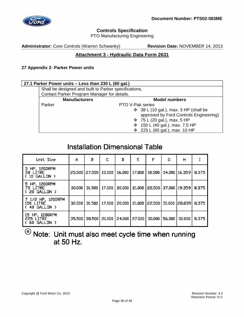
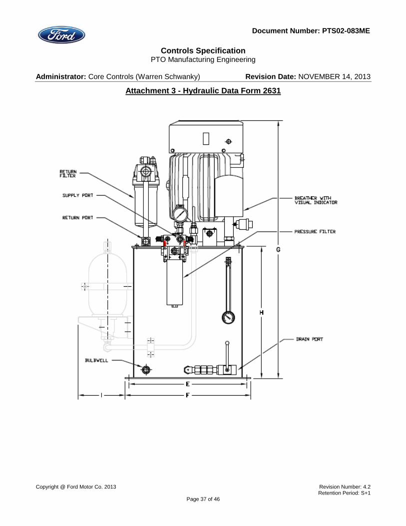
27 Appendix 2- Parker Power units 27.1 Parker Power units – Less than 230 L (60 gal.) Shall be designed and built to Parker specifications.
Contact Parker Program Manager for details. Manufacturers Model numbers Parker PTO V-Pak series
38 L (10 gal.), max. 3 HP (shall be approved by Ford Controls Engineering)
75 L (20 gal.), max. 5 HP 150 L (40 gal.), max. 7.5 HP 225 L (60 gal.), max. 10 HP
Copyright @ Ford Motor Co. 2013 Revision Number: 4.2 Retention Period: S+1
Page 36 of 46
Controls Specification
PTO Manufacturing Engineering Administrator: Core Controls (Warren Schwanky) Revision Date: NOVEMBER 14, 2013
Attachment 3 - Hydraulic Data Form 2631
Document Number: PTS02-083ME
Copyright @ Ford Motor Co. 2013 Revision Number: 4.2 Retention Period: S+1
Page 37 of 46

Controls Specification
PTO Manufacturing Engineering Administrator: Core Controls (Warren Schwanky) Revision Date: NOVEMBER 14, 2013
Attachment 3 - Hydraulic Data Form 2631
Document Number: PTS02-083ME
Copyright @ Ford Motor Co. 2013 Revision Number: 4.2 Retention Period: S+1
Page 38 of 46

Controls Specification
PTO Manufacturing Engineering Administrator: Core Controls (Warren Schwanky) Revision Date: NOVEMBER 14, 2013
Attachment 3 - Hydraulic Data Form 2631
Document Number: PTS02-083ME
Copyright @ Ford Motor Co. 2013 Revision Number: 4.2 Retention Period: S+1
Page 39 of 46

Controls Specification
PTO Manufacturing Engineering Administrator: Core Controls (Warren Schwanky) Revision Date: NOVEMBER 14, 2013
Attachment 3 - Hydraulic Data Form 2631
Document Number: PTS02-083ME
27.2 Parker Power units – Greater than 230 L (60 gal.) Shall be designed and built to Parker specifications.
Heat exchangers shall be approved by Ford Controls Engineering. All power units over 230 L (60 gal.) shall have flooded inlet design. All reservoirs shall be pressure filled through the return line filter. All return lines shall have a check valve between the tank and filter. The return line filter shall have check valves to prevent oil spillage when changing the element. Do not use anti-siphon holes on return lines. Power units over 570 L shall use off-line pump/motor for filtering and cooling. Power units from 378-569 L shall have all required mounting provisions for installation of off-line pump/motor for filtering and cooling. Pump case drain lines shall be one size larger than the port size of the pump. Double pump arrangements are allowable. (Triple pump combinations will not be accepted). System pressure must be lowered during time of extended standby to minimize heat.
Manufacturers Model numbers Parker PTO FPS-Pak II series
400-600 L (100-160 gal.), 35-52 HP (26-39.5 kW), or 10-25 HP (7.5-18.6 kW) without heat exchanger.
600-1200 L (160-320 gal.), – 52-80 HP (39.5-60 kW), or 25-35 HP (18.6-26 kW) without heat exchanger.
1200-1600 L (320-420 gal.), 80-125 HP (60-93 kW), or 35-40 HP (26-30 kW) without heat exchanger.
Copyright @ Ford Motor Co. 2013 Revision Number: 4.2 Retention Period: S+1
Page 40 of 46

Controls Specification
PTO Manufacturing Engineering Administrator: Core Controls (Warren Schwanky) Revision Date: NOVEMBER 14, 2013
Attachment 3 - Hydraulic Data Form 2631
Document Number: PTS02-083ME
Copyright @ Ford Motor Co. 2013 Revision Number: 4.2 Retention Period: S+1
Page 41 of 46

Controls Specification
PTO Manufacturing Engineering Administrator: Core Controls (Warren Schwanky) Revision Date: NOVEMBER 14, 2013
Attachment 3 - Hydraulic Data Form 2631
Document Number: PTS02-083ME
Copyright @ Ford Motor Co. 2013 Revision Number: 4.2 Retention Period: S+1
Page 42 of 46

Controls Specification
PTO Manufacturing Engineering Administrator: Core Controls (Warren Schwanky) Revision Date: NOVEMBER 14, 2013
Attachment 3 - Hydraulic Data Form 2631
Document Number: PTS02-083ME
Copyright @ Ford Motor Co. 2013 Revision Number: 4.2 Retention Period: S+1
Page 43 of 46

Controls Specification
PTO Manufacturing Engineering Administrator: Core Controls (Warren Schwanky) Revision Date: NOVEMBER 14, 2013
Attachment 3 - Hydraulic Data Form 2631
Document Number: PTS02-083ME
28 Record of changes and amendments Revision 0 – 08/14/2008 Initial release.
Revision 1 – 10/06/2008 No changes.
Revision 2 – 12/12/2008 No changes.
Revision 3 – 08/18/2009 22.16 Added new part number. None specified before. 22.17 Added new part number. None specified before. 22.18 Added new part numbers. None specified before.
Revision 4 — 07/15/2011 All Combined Main and Bosch-Rexroth supplement. Parker supplement was deleted.
Revision 4.1— 03/30/2012 Global changes
Added Parker part numbers in addition to Bosch-Rexroth. Moved Bosch-Rexroth Hydraulic power units drawings to appendix 1. Added Parker Hydraulic power units to Appendix 2
1.1 Part number was changed from BR HAB….series to Parker BA***B3R01-AS1 1.2 Part number was changed from A6E****L2KRF to Parker A6E****SL2KRF 1.3 Changed name of position from “ Dump valve” to Accumulator safety block. 1.4 Part number was changed from1468970002 to 870760. Added BR Part number 1.5 Added the new section. 4.1 Added KTR coupling. 9.1 Added BR gauges. 10.2 Added Funke Heat exchanger 11.6 Added BR part number 12.1 Added HSR manifolds. 13.3 Updated Piston pumps part numbers 14.2 Updated Piston Axial pumps part numbers 14.4 Updated Vane pumps part numbers 16.1 Added BR breather 16.2 Added BR fluid level. 19.1 Added BR surge suppressors 22.4 Added BR part number 22.5 Added BR part number
Copyright @ Ford Motor Co. 2013 Revision Number: 4.2 Retention Period: S+1
Page 44 of 46

Controls Specification
PTO Manufacturing Engineering Administrator: Core Controls (Warren Schwanky) Revision Date: NOVEMBER 14, 2013
Attachment 3 - Hydraulic Data Form 2631
Document Number: PTS02-083ME
22.6 Added BR part number 22.11 Added DBDS BR series 22.13 Modified part BR part number 22.15 Modified part BR part number A Added 40L HPU A Removed 70L HPU. Added 60L HPU
LEGENDS
REASON FOR CHANGE COST IMPACTS C COST CD COST DECREASE
MS MULTI SOURCE CIN COST INCREASE L LEGAL NT NEUTRAL M MAINTENANCE N NEW CATEGORY OF
PRODUCTS
O OBSOLESENCE P PERFORMANCE S SAFETY U UPDATED/CHANGED
PART NUMBER
CL CLARIFICATION
Copyright @ Ford Motor Co. 2013 Revision Number: 4.2 Retention Period: S+1
Page 45 of 46

Controls Specification
PTO Manufacturing Engineering Administrator: Core Controls (Warren Schwanky) Revision Date: NOVEMBER 14, 2013
Attachment 3 - Hydraulic Data Form 2631
Document Number: PTS02-083ME
Revision 4.2 – AUGUST 30, 2013 Revision
# Section DESCRIPTION OF CHANGES REASON
FOR CHANGE
COST IMPACT
COMMENTS
4.2 1.3 Parker accumulator block is changed to lockable type. Updated Bosch Rexroth part #.
S NT
4.2 1.4 Removed Bosch fuse due to obsolescence.
O NT
4.2 5.1 Added Bosch Rexroth filter elements N NT 4.2 5.2 Added description of filters capacity.
Added Bosch filters. U C
NT CD
4.2 10.2 Added Parker water-oil heat exchanger.
4.2 10.4 Added Water chiller section. N NT 4.2 11.1 Added hose for Cat Track
applications. N NT
4.2 16.1 Changed breather filtering requirements from 3 to 10 microns..Added Bosch breathers.
U NT
4.2 22.1 Added Parker lockable valves BVHP, BVAH.
N NT
4.2 22.2 Added DMIC as the direct source for ball valves.
N NT
4.2 22.3 Added Bosch Rexroth standard cavity
N NT
4.2 22.4 Added Compact version of Bosch cartridge valve.
N CD
4.2 22.7 Added Bosch and Sun hydraulics Pilot check valves with manual override.
N P
CD
4.2 22.10 Removed obsolete VRPD** O NT 4.2 22.12 Removed obsolete VSQY** O NT 4.2 22.16,
22.17, 22.18
Modified part numbers. U NT
4.2 22.22 Changed part numbers description. U NT 4.2 27.1 Removed dBA requirements. CL NT 4.2 27.2 Removed dBA requirements. CL NT
Copyright @ Ford Motor Co. 2013 Revision Number: 4.2 Retention Period: S+1
Page 46 of 46