ptical Short Course International - loreti.it · case the display device is the digital projector....
10
Copyright 2005 OSCI Vol. 1 No. 31 11 April 2005 http://www.oscintl.com 1 (520) 797-9744 ptical Short Course International 6679 N. Calle de Calipso, Tucson, AZ http://www.oscintl.com 520-797-9744 What’s “In The Box”? Optics of Digital Projectors Weekly Newsletter Sponsored By: The Brand for highest quality and competence in Light Management Solutions™ for Projection Display Download brochure (PDF) => Light Management Solutions™ for Projection Display Visit Homepage => www.optics.unaxis.com Anamorphic Projection Lens Attachments on Digital Projectors By Michael Pate, President, OSCI Anamorphic projection lens attachments are used in conjunction with the image scaler electronics to change the height to width ratio of the image displayed on the viewing screen. In this version of In The Box we are going to discuss anamorphic projection lens attachments.
Transcript of ptical Short Course International - loreti.it · case the display device is the digital projector....

Copyright 2005 OSCI Vol. 1 No. 31 11 April 2005 http://www.oscintl.com 1 (520) 797-9744
ptical Short Course International 6679 N. Calle de Calipso, Tucson, AZ http://www.oscintl.com 520-797-9744
What’s “In The Box”?
Optics of Digital Projectors Weekly Newsletter
Sponsored By:
The Brand for highest quality and competence in
Light Management Solutions™ for Projection Display
Download brochure (PDF) => Light Management Solutions™ for Projection Display Visit Homepage => www.optics.unaxis.com
Anamorphic Projection Lens Attachments on Digital Projectors By Michael Pate, President, OSCI
Anamorphic projection lens attachments are used in conjunction with the image scaler electronics to change the height to width ratio of the image displayed on the viewing screen. In this version of In The Box we are going to discuss anamorphic projection lens attachments.
Copyright 2005 OSCI Vol. 1 No. 31 11 April 2005 http://www.oscintl.com 2 (520) 797-9744
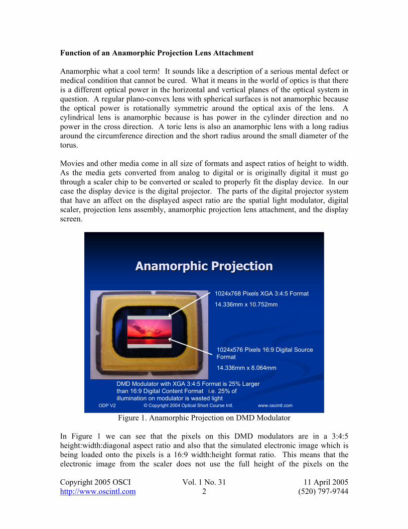
Function of an Anamorphic Projection Lens Attachment Anamorphic what a cool term! It sounds like a description of a serious mental defect or medical condition that cannot be cured. What it means in the world of optics is that there is a different optical power in the horizontal and vertical planes of the optical system in question. A regular plano-convex lens with spherical surfaces is not anamorphic because the optical power is rotationally symmetric around the optical axis of the lens. A cylindrical lens is anamorphic because is has power in the cylinder direction and no power in the cross direction. A toric lens is also an anamorphic lens with a long radius around the circumference direction and the short radius around the small diameter of the torus. Movies and other media come in all size of formats and aspect ratios of height to width. As the media gets converted from analog to digital or is originally digital it must go through a scaler chip to be converted or scaled to properly fit the display device. In our case the display device is the digital projector. The parts of the digital projector system that have an affect on the displayed aspect ratio are the spatial light modulator, digital scaler, projection lens assembly, anamorphic projection lens attachment, and the display screen.
ODP V2 © Copyright 2004 Optical Short Course Intl. www.oscintl.com
Anamorphic ProjectionAnamorphic Projection
1024x768 Pixels XGA 3:4:5 Format
14.336mm x 10.752mm
1024x576 Pixels 16:9 Digital Source Format
14.336mm x 8.064mm
DMD Modulator with XGA 3:4:5 Format is 25% Larger than 16:9 Digital Content Format i.e. 25% of illumination on modulator is wasted light
Figure 1. Anamorphic Projection on DMD Modulator
In Figure 1 we can see that the pixels on this DMD modulators are in a 3:4:5 height:width:diagonal aspect ratio and also that the simulated electronic image which is being loaded onto the pixels is a 16:9 width:height format ratio. This means that the electronic image from the scaler does not use the full height of the pixels on the
Copyright 2005 OSCI Vol. 1 No. 31 11 April 2005 http://www.oscintl.com 3 (520) 797-9744
modulator. We can see this in the Figure 1 above. We see 768 pixels high modulator and only 576 pixels high electronic image in the 16:9 format. So we have two stripes at the top and bottom of the modulator that are being illuminated by the optical system with light but this light must be turned off and not used by the modulator. The total area of the two stripes is equal to 25% of the modulator area, so we are wasting 25% of the illumination from the light source. We can project a 16:9 image and waste this 25% of the total lumens on the modulator panel. However all good illumination designers know that a photon is a terrible thing to waste so we like to have innovative methods to use these useful photons in the top and bottom stripe of unused modulator area.
ODP V2 © Copyright 2004 Optical Short Course Intl. www.oscintl.com
Anamorphic ProjectionAnamorphic Projection1024x768 Pixels XGA 3:4:5 Format
14.336mm x 10.752mm
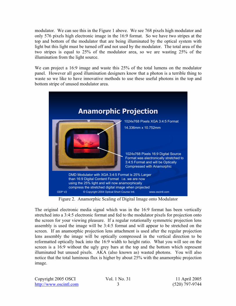
1024x768 Pixels 16:9 Digital Source Format was electronically stretched to 3:4:5 Format and will be Optically Compressed with Anamorphic
DMD Modulator with XGA 3:4:5 Format is 25% Larger than 16:9 Digital Content Format i.e. we are now using the 25% light and will now anamorphically compress the stretched digital image when projected
Figure 2. Anamorphic Scaling of Digital Image onto Modulator
The original electronic media signal which was in the 16:9 format has been vertically stretched into a 3:4:5 electronic format and fed to the modulator pixels for projection onto the screen for your viewing pleasure. If a regular rotationally symmetric projection lens assembly is used the image will be 3:4:5 format and will appear to be stretched on the screen. If an anamorphic projection lens attachment is used after the regular projection lens assembly the image will be optically compressed in the vertical direction to be reformatted optically back into the 16:9 width to height ratio. What you will see on the screen is a 16:9 without the ugly grey bars at the top and the bottom which represent illuminated but unused pixels. AKA (also known as) wasted photons. You will also notice that the total luminous flux is higher by about 25% with the anamorphic projection image.
Copyright 2005 OSCI Vol. 1 No. 31 11 April 2005 http://www.oscintl.com 4 (520) 797-9744
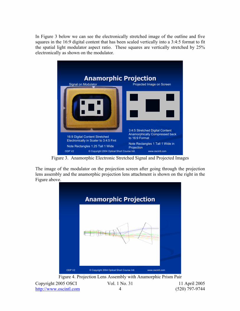
In Figure 3 below we can see the electronically stretched image of the outline and five squares in the 16:9 digital content that has been scaled vertically into a 3:4:5 format to fit the spatial light modulator aspect ratio. These squares are vertically stretched by 25% electronically as shown on the modulator.
ODP V2 © Copyright 2004 Optical Short Course Intl. www.oscintl.com
Anamorphic ProjectionAnamorphic Projection
16:9 Digital Content Stretched Electronically in Scaler to 3:4:5 Fmt
Note Rectangles 1.25 Tall 1 Wide
3:4:5 Stretched Digital Content Anamorphically Compressed back to 16:9 Format
Note Rectangles 1 Tall 1 Wide in Projection
Signal on Modulator Projected Image on Screen
Figure 3. Anamorphic Electronic Stretched Signal and Projected Images
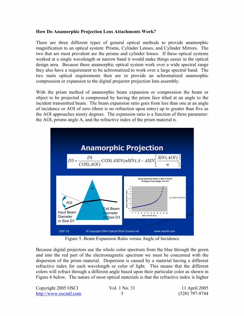
The image of the modulator on the projection screen after going through the projection lens assembly and the anamorphic projection lens attachment is shown on the right in the Figure above.
ODP V2 © Copyright 2004 Optical Short Course Intl. www.oscintl.com
Anamorphic ProjectionAnamorphic Projection
Figure 4. Projection Lens Assembly with Anamorphic Prism Pair
Copyright 2005 OSCI Vol. 1 No. 31 11 April 2005 http://www.oscintl.com 5 (520) 797-9744
How Do Anamorphic Projection Lens Attachments Work? There are three different types of general optical methods to provide anamorphic magnification to an optical system: Prisms, Cylinder Lenses, and Cylinder Mirrors. The two that are most prevalent are the prisms and cylinder lenses. If these optical systems worked at a single wavelength or narrow band it would make things easier in the optical design area. Because these anamorphic optical system work over a wide spectral range they also have a requirement to be achromatized to work over a large spectral band. The two main optical requirements then are to provide an achromatized anamorphic compression or expansion to the digital projector projection lens assembly. With the prism method of anamorphic beam expansion or compression the beam or object to be projected is compressed by having the prism face tilted at an angle to the incident transmitted beam. The beam expansion ratio goes from less than one at an angle of incidence or AOI of zero (there is no refraction upon entry) up to greater than five as the AOI approaches ninety degrees. The expansion ratio is a function of three parameter: the AOI, prisms angle A, and the refractive index of the prism material n.
ODP V2 © Copyright 2004 Optical Short Course Intl. www.oscintl.com
Anamorphic ProjectionAnamorphic Projection
Beam Expansion Ratio vs AOI on Prism30 Degree Prism Angle, N=1.517
00.5
11.5
22.5
33.5
44.5
5
0 8 16 24 32 40 48 56 64 72 80 88
AOI on Prism Face
Beam
Exp
ansi
on R
atio
Beam Expansion
AOI
A
Input Beam Diameter or Size D1
Exit Beam Diameter or Size D3
−=
nAOISINASINAnSINASINCOS
AOICOSDD )((((
)(13
Figure 5. Beam Expansion Ratio versus Angle of Incidence
Because digital projectors use the whole color spectrum from the blue through the green and into the red part of the electromagnetic spectrum we must be concerned with the dispersion of the prism material. Dispersion is caused by a material having a different refractive index for each wavelength or color of light. This means that the different colors will refract through a different angle based upon their particular color as shown in Figure 6 below. The nature of most optical materials is that the refractive index is higher

Copyright 2005 OSCI Vol. 1 No. 31 11 April 2005 http://www.oscintl.com 6 (520) 797-9744
for lower wavelengths, so blue will be refracted the most and red the least as shown in Figure 6 below.
ODP V2 © Copyright 2004 Optical Short Course Intl. www.oscintl.com
Anamorphic ProjectionAnamorphic Projection
A
Refractive Index Variation with Wavelength or Color Causes Dispersion of Color in Prism upon Refraction
Figure 6. Prism Dispersion
ODP V2 © Copyright 2004 Optical Short Course Intl. www.oscintl.com
Anamorphic ProjectionAnamorphic Projection
Figure 7. Achromatic Prism Pair
Copyright 2005 OSCI Vol. 1 No. 31 11 April 2005 http://www.oscintl.com 7 (520) 797-9744
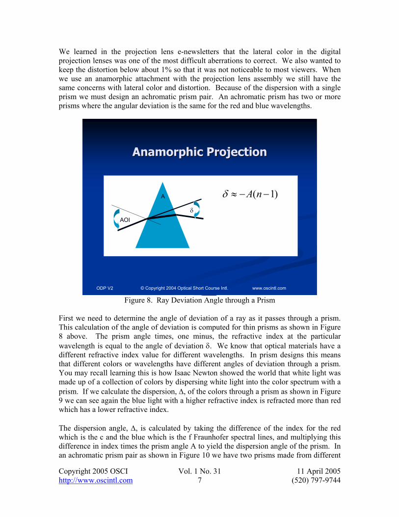
We learned in the projection lens e-newsletters that the lateral color in the digital projection lenses was one of the most difficult aberrations to correct. We also wanted to keep the distortion below about 1% so that it was not noticeable to most viewers. When we use an anamorphic attachment with the projection lens assembly we still have the same concerns with lateral color and distortion. Because of the dispersion with a single prism we must design an achromatic prism pair. An achromatic prism has two or more prisms where the angular deviation is the same for the red and blue wavelengths.
ODP V2 © Copyright 2004 Optical Short Course Intl. www.oscintl.com
Anamorphic ProjectionAnamorphic Projection
AOI
A
δ
)1( −−≈ nAδ
Figure 8. Ray Deviation Angle through a Prism
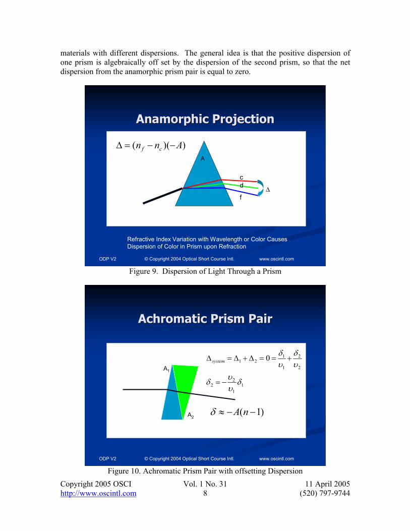
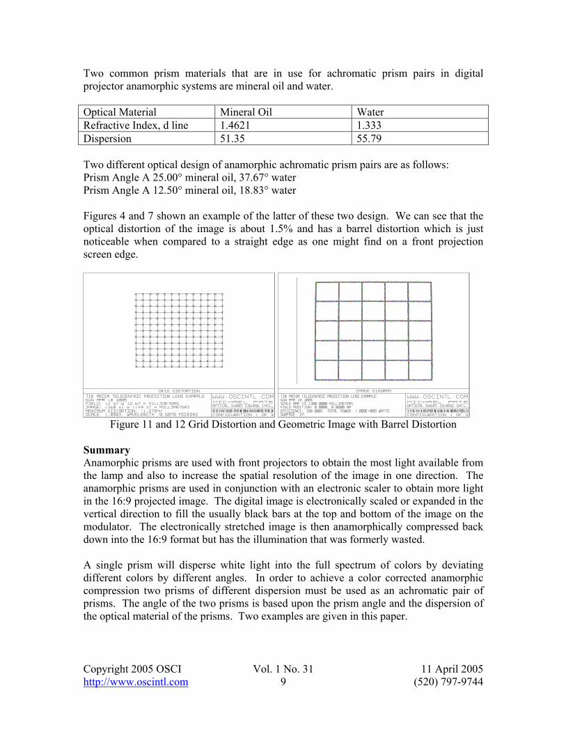
First we need to determine the angle of deviation of a ray as it passes through a prism. This calculation of the angle of deviation is computed for thin prisms as shown in Figure 8 above. The prism angle times, one minus, the refractive index at the particular wavelength is equal to the angle of deviation δ. We know that optical materials have a different refractive index value for different wavelengths. In prism designs this means that different colors or wavelengths have different angles of deviation through a prism. You may recall learning this is how Isaac Newton showed the world that white light was made up of a collection of colors by dispersing white light into the color spectrum with a prism. If we calculate the dispersion, ∆, of the colors through a prism as shown in Figure 9 we can see again the blue light with a higher refractive index is refracted more than red which has a lower refractive index. The dispersion angle, ∆, is calculated by taking the difference of the index for the red which is the c and the blue which is the f Fraunhofer spectral lines, and multiplying this difference in index times the prism angle A to yield the dispersion angle of the prism. In an achromatic prism pair as shown in Figure 10 we have two prisms made from different
Copyright 2005 OSCI Vol. 1 No. 31 11 April 2005 http://www.oscintl.com 8 (520) 797-9744
materials with different dispersions. The general idea is that the positive dispersion of one prism is algebraically off set by the dispersion of the second prism, so that the net dispersion from the anamorphic prism pair is equal to zero.
ODP V2 © Copyright 2004 Optical Short Course Intl. www.oscintl.com
Anamorphic ProjectionAnamorphic Projection
A
Refractive Index Variation with Wavelength or Color Causes Dispersion of Color in Prism upon Refraction
∆
))(( Ann cf −−=∆
f
dc
Figure 9. Dispersion of Light Through a Prism
ODP V2 © Copyright 2004 Optical Short Course Intl. www.oscintl.com
Achromatic Prism PairAchromatic Prism Pair
11
22
2
2
1
121 0
δυυδ
υδ
υδ
−=
+==∆+∆=∆ systemA1
A2)1( −−≈ nAδ
Figure 10. Achromatic Prism Pair with offsetting Dispersion
Copyright 2005 OSCI Vol. 1 No. 31 11 April 2005 http://www.oscintl.com 9 (520) 797-9744
Two common prism materials that are in use for achromatic prism pairs in digital projector anamorphic systems are mineral oil and water. Optical Material Mineral Oil Water Refractive Index, d line 1.4621 1.333 Dispersion 51.35 55.79 Two different optical design of anamorphic achromatic prism pairs are as follows: Prism Angle A 25.00° mineral oil, 37.67° water Prism Angle A 12.50° mineral oil, 18.83° water Figures 4 and 7 shown an example of the latter of these two design. We can see that the optical distortion of the image is about 1.5% and has a barrel distortion which is just noticeable when compared to a straight edge as one might find on a front projection screen edge.
Figure 11 and 12 Grid Distortion and Geometric Image with Barrel Distortion
Summary Anamorphic prisms are used with front projectors to obtain the most light available from the lamp and also to increase the spatial resolution of the image in one direction. The anamorphic prisms are used in conjunction with an electronic scaler to obtain more light in the 16:9 projected image. The digital image is electronically scaled or expanded in the vertical direction to fill the usually black bars at the top and bottom of the image on the modulator. The electronically stretched image is then anamorphically compressed back down into the 16:9 format but has the illumination that was formerly wasted. A single prism will disperse white light into the full spectrum of colors by deviating different colors by different angles. In order to achieve a color corrected anamorphic compression two prisms of different dispersion must be used as an achromatic pair of prisms. The angle of the two prisms is based upon the prism angle and the dispersion of the optical material of the prisms. Two examples are given in this paper.
Copyright 2005 OSCI Vol. 1 No. 31 11 April 2005 http://www.oscintl.com 10 (520) 797-9744
Stay tuned and keep looking for your frequent dose of “In The Box” to understand the optics of digital projectors. If you enjoy increasing your knowledge about digital projector optics please tell a friend about this e-newletter, or even send them a copy, your referral is the kindest compliment we can get to show your appreciation. Advertising opportunities are available for qualified companies in the digital projector industry. Please contact OSCI to inquire about projecting your company image to the industry.