PTC/User Montreal Creating a Sheet Metal Assembly.
14
-
Upload
isaac-nash -
Category
Documents
-
view
220 -
download
4
Transcript of PTC/User Montreal Creating a Sheet Metal Assembly.


PTC/User Montreal
Creating a Sheet Metal Assembly

Topics Covered
• Skeleton in Sheet Metal Assembly
• Sheet Metal Parameters
• Convert Solid Model to Sheet Metal Model
• Copy Geometry
• Mirror a Part in Assembly
• Assembly

Skeleton in Assemblies
Skeleton: A special component of an assembly
• Created only within an assembly • Placed before all other components • Solid geometry in the model tree • Filtered out the BOM and drawing views• Specially handled for Simplified Reps and
Shrink-wrap features • Maintain their own family tables

Skeleton in Assemblies
Skeleton: The framework of the assembly
• Defines skeletal, space claim, interface, and other physical properties of an assembly
• Defines geometry of components • Perform motion analysis on an
assembly
Example:Monitor Shielding Shell

Using the skeleton
Dependent on Skeleton
by CopyGeom
VS
Completely Independent
from Skeleton
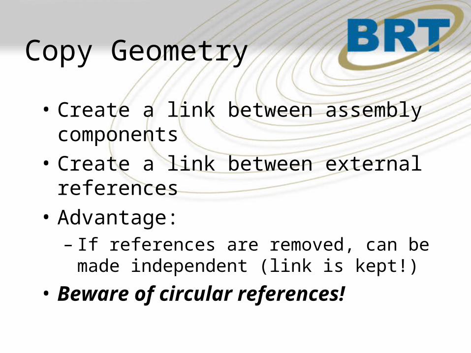
Copy Geometry
• Create a link between assembly components
• Create a link between external references
• Advantage:– If references are removed, can be made
independent (link is kept!)
• Beware of circular references!

Sheet Metal Parameters
• Special kind of model parameters
• Help centralize Sheet Metal Information
• Automate the Sheet Metal Design
• Set up before modeling

Example
Converting Solid Models to Sheet Metal Models
• Solid Models can be converted by:– Selecting a driving surface
• Solid model created with thin option
– Shelling the model
• When should you convert?– Corners
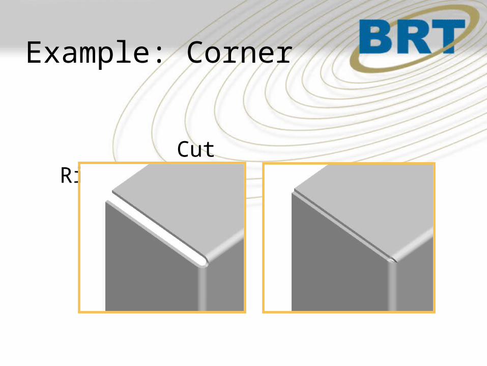
Example: Corner
Cut Rip
Mirroring a Part in Assembly
• Creates an exact mirror copy– Independent (Copy)– Dependant (Reference)
• Part with Reference– No reference to the assembly if datum or
plane belongs to original part
• Subassembly– Always a reference with Original Assembly

Summary
• Skeleton & Copy Geometry can play an important role in a Sheet Metal assembly
• Sheet metal Parameters help automate sheet metal models
• Sheet metal components can be created by converting solid geometry – Very useful for corners


![Forging plant PTC KAMAZ eng 27.07.17 [ ]) plant PTC KAMAZ eng 27... · Forging plant KAMAZ PTC ... Cutting of rolled metal into billets, forging process, heat treatment, ... • Front](https://static.fdocuments.us/doc/165x107/5b070f947f8b9a79538d5bf1/forging-plant-ptc-kamaz-eng-270717-plant-ptc-kamaz-eng-27forging-plant.jpg)