PTB 200 DIGITAL BAROMETERS - Vaisala 200 2 (28) Digital Barometers SSD/Operating Manual 24th...
30
PTB 200 1 (28) Digital Barometers SSD/Operating Manual 24th February 1993 PTB200-O0284-1.1 PTB 200 DIGITAL BAROMETERS 1 PRODUCT DESCRIPTION 2 2 INSTALLATION 3 2.1 Mounting 3 2.2 Grounding 4 2.3 Power connections 5 2.4 Serial output mode connections 6 2.5 Pulse output mode connections 7 2.6 Pressure connections 8 2.7 Multiple barometers on one RS 232C bus 9 3 SERIAL COMMANDS 10 3.1 General 10 3.2 Configuration commands 11 3.3 Operating commands 19 4 ADJUSTMENT AND CALIBRATION 22 4.1 Offset and gain adjustment 23 4.2 Multipoint adjustment 24 5 TECHNICAL DATA 26 Appendix 1 Commands
Transcript of PTB 200 DIGITAL BAROMETERS - Vaisala 200 2 (28) Digital Barometers SSD/Operating Manual 24th...

PTB 200 1 (28)Digital Barometers
SSD/Operating Manual 24th February 1993 PTB200-O0284-1.1
PTB 200 DIGITAL BAROMETERS
1 PRODUCT DESCRIPTION 2
2 INSTALLATION 3
2.1 Mounting 32.2 Grounding 42.3 Power connections 52.4 Serial output mode connections 62.5 Pulse output mode connections 72.6 Pressure connections 82.7 Multiple barometers on one RS 232C bus 9
3 SERIAL COMMANDS 10
3.1 General 103.2 Configuration commands 113.3 Operating commands 19
4 ADJUSTMENT AND CALIBRATION 22
4.1 Offset and gain adjustment 234.2 Multipoint adjustment 24
5 TECHNICAL DATA 26
Appendix 1 Commands
PTB200 Digital BarometerAppendix 1
1994-08-16 1
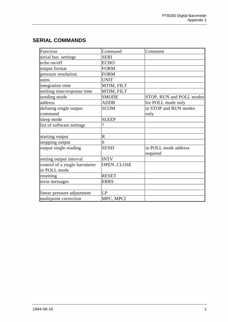
SERIAL COMMANDS
Function Command Commentserial bus settings SERIecho on/off ECHOoutput format FORMpressure resolution FORMunits UNITintegration time MTIM, FILTsettling time/response time MTIM, FILTsending mode SMODE STOP, RUN and POLL modesaddress ADDR for POLL mode onlydefining single outputcommand
SCOM in STOP and RUN modesonly
sleep mode SLEEPlist of software settings ?
starting output Rstopping output Soutput single reading SEND in POLL mode address
requiredsetting output interval INTVcontrol of a single barometerin POLL mode
OPEN ,CLOSE
resetting RESETerror messages ERRS
linear pressure adjustment LPmultipoint correction MPC, MPCI
PTB 200 2 (28)Digital Barometers
SSD/Operating Manual 24th February 1993 PTB200-O0284-1.1
1 PRODUCT DESCRIPTION
The PTB 200 A and PTB 201 A are fully compensated digital barome-ters designed to operate over a wide pressure and temperature range.The final factory adjustment and calibration of the PTB 200 A is doneagainst a deadweight tester for best accuracy and pressure traceability.The PTB 201 A is adjusted and calibrated by using electronic workingstandards to meet the requirements of demanding weather stationapplications. The PTB 200 digital barometers can also be readjusted bythe user with a local primary standard at up to eight selectable pressurelevels.
There are three available outputs in the PTB 200 digital barometers.The RS 232C full duplex serial interface with software selectable serialbus settings and pressure units is the standard output for connectionwith computers. The user can also choose a TTL level bidirectionalserial output. For simple data logger use the pulse output can beselected. The serial output of the PTB 200 barometers can be used incontinuous, interval or on-demand modes. The pulse output is activatedby an external trigger signal.
The PTB 200 digital barometers have two built-in features to reducepower consumption; the user can choose a software controlled sleepmode or use an external trigger signal to shut down the barometer.
The user can define various settings, such as integration time, settlingtime and pressure resolution according to his application (see chaptersGeneral and Configuration commands). The factory settings have beenchosen so that both a fast settling time and high resolution areachieved. In applications where fast settling time is not required, werecommend longer integration times to suppress noise effects such aswind turbulance.
The PTB 200 digital barometers use Vaisala’s BAROCAP siliconcapacitive absolute pressure sensor. The BAROCAP pressure sensorhas excellent hysteresis and repeatability characteristics and very goodtemperature and long-term stability. The ruggedness of the BAROCAPsensor is outstanding.
From April 1993, the PTB 200 digital barometers are traceable to NISTin the USA. Until March 1993 the barometers have been traceable toL.N.E. in France.
PTB 200 3 (28)Digital Barometers
SSD/Operating Manual 24th February 1993 PTB200-O0284-1.1
2 INSTALLATION
2.1 Mounting
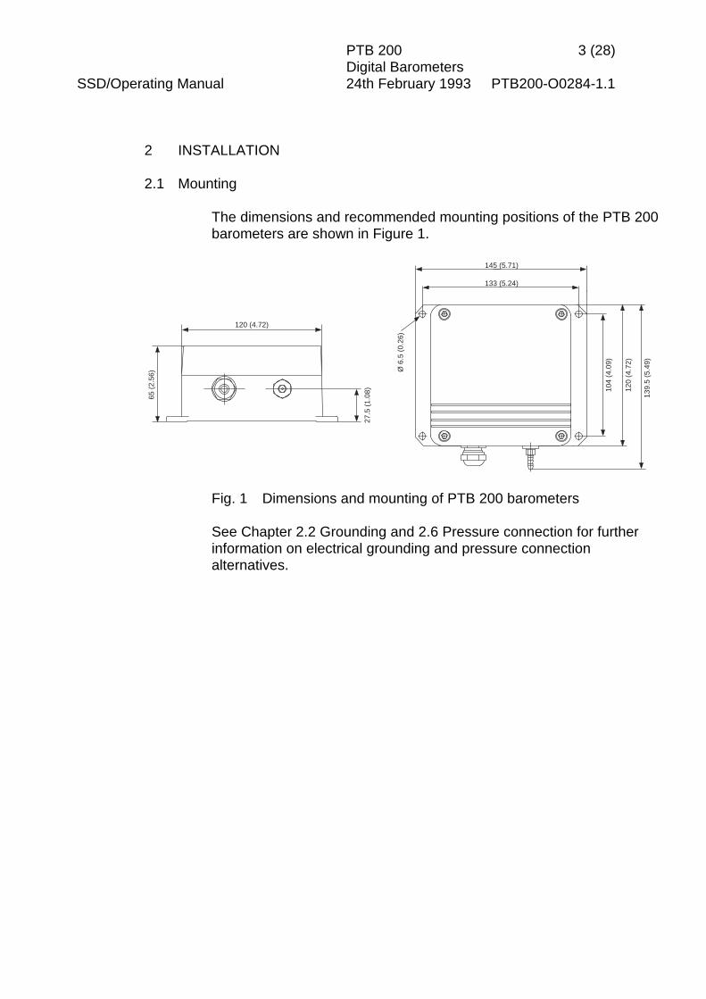
The dimensions and recommended mounting positions of the PTB 200barometers are shown in Figure 1.
27.5
(1.
08)
120 (4.72)
65 (
2.56
) Ø 6
.5 (
0.26
)
104
(4.0
9)
139.
5 (5
.49)
145 (5.71)
133 (5.24)
120
(4.7
2)
Fig. 1 Dimensions and mounting of PTB 200 barometers
See Chapter 2.2 Grounding and 2.6 Pressure connection for furtherinformation on electrical grounding and pressure connectionalternatives.
PTB 200 4 (28)Digital Barometers
SSD/Operating Manual 24th February 1993 PTB200-O0284-1.1
2.2 Grounding
A single electrical cable with a screen and five or six wires isrecommended for power and serial bus connections. The cablediameter should be 5 ... 10 mm.
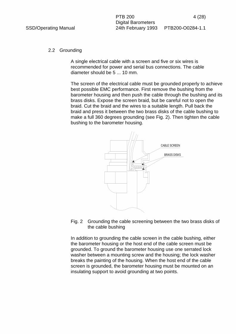
The screen of the electrical cable must be grounded properly to achievebest possible EMC performance. First remove the bushing from thebarometer housing and then push the cable through the bushing and itsbrass disks. Expose the screen braid, but be careful not to open thebraid. Cut the braid and the wires to a suitable length. Pull back thebraid and press it between the two brass disks of the cable bushing tomake a full 360 degrees grounding (see Fig. 2). Then tighten the cablebushing to the barometer housing.
CABLE SCREEN
BRASS DISKS
Fig. 2 Grounding the cable screening between the two brass disks ofthe cable bushing
In addition to grounding the cable screen in the cable bushing, eitherthe barometer housing or the host end of the cable screen must begrounded. To ground the barometer housing use one serrated lockwasher between a mounting screw and the housing; the lock washerbreaks the painting of the housing. When the host end of the cablescreen is grounded, the barometer housing must be mounted on aninsulating support to avoid grounding at two points.
PTB 200 5 (28)Digital Barometers
SSD/Operating Manual 24th February 1993 PTB200-O0284-1.1
2.3 Power connections
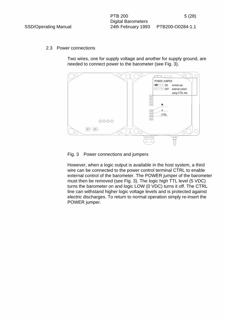
Two wires, one for supply voltage and another for supply ground, areneeded to connect power to the barometer (see Fig. 3).
POWER JUMPERONOFF
-CTRL
+
normal useexternal controlusing CTRL line
Fig. 3 Power connections and jumpers
However, when a logic output is available in the host system, a thirdwire can be connected to the power control terminal CTRL to enableexternal control of the barometer. The POWER jumper of the barometermust then be removed (see Fig. 3). The logic high TTL level (5 VDC)turns the barometer on and logic LOW (0 VDC) turns it off. The CTRLline can withstand higher logic voltage levels and is protected againstelectric discharges. To return to normal operation simply re-insert thePOWER jumper.
PTB 200 6 (28)Digital Barometers
SSD/Operating Manual 24th February 1993 PTB200-O0284-1.1
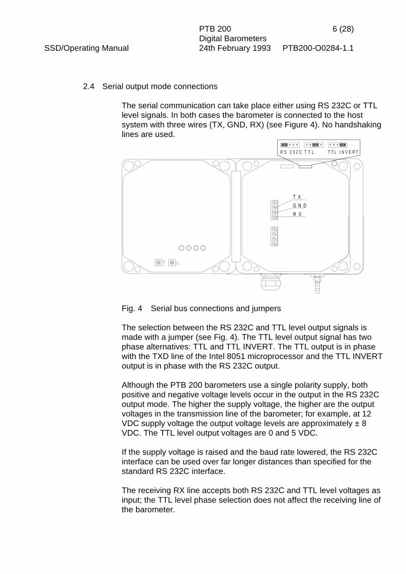
2.4 Serial output mode connections
The serial communication can take place either using RS 232C or TTLlevel signals. In both cases the barometer is connected to the hostsystem with three wires (TX, GND, RX) (see Figure 4). No handshakinglines are used.
G N D
R X
T X
R S 2 3 2 C T T L T T L I N V E R T
Fig. 4 Serial bus connections and jumpers
The selection between the RS 232C and TTL level output signals ismade with a jumper (see Fig. 4). The TTL level output signal has twophase alternatives: TTL and TTL INVERT. The TTL output is in phasewith the TXD line of the Intel 8051 microprocessor and the TTL INVERToutput is in phase with the RS 232C output.
Although the PTB 200 barometers use a single polarity supply, bothpositive and negative voltage levels occur in the output in the RS 232Coutput mode. The higher the supply voltage, the higher are the outputvoltages in the transmission line of the barometer; for example, at 12VDC supply voltage the output voltage levels are approximately ± 8VDC. The TTL level output voltages are 0 and 5 VDC.
If the supply voltage is raised and the baud rate lowered, the RS 232Cinterface can be used over far longer distances than specified for thestandard RS 232C interface.
The receiving RX line accepts both RS 232C and TTL level voltages asinput; the TTL level phase selection does not affect the receiving line ofthe barometer.

PTB 200 7 (28)Digital Barometers
SSD/Operating Manual 24th February 1993 PTB200-O0284-1.1
2.5 Pulse output mode connections (software version 1.05 or higher)
The pulse output mode uses the same terminals as the serial outputmode (see Figure 5). The transmitting terminal sends the pulse output(TX/PULSE) and the receiving terminal of the barometer receives thepositive trigger signal (RX/PULSE TRIG).
SERIAL OUTPUTMODE SELECT
PULSE OUTPUTMODE SELECT
LEDS
GND
PULSE TRIG
PULSE
RS 232C TTL TTL INVERT
PUSH BUTTONS:
Fig. 5 Pulse output connections, jumpers and push buttons
The pulse output mode must be separately selected. Two push buttons(Fig. 5), arrow up and arrow down, are used to switch between thepulse output mode and the serial output mode.
To select the PULSE OUTPUT operation mode:1. Set the baud rate to 9600 (see SERI command).2. Switch power off.3. Press and keep down the arrow down push button.4. Switch power on; the four LEDs go on and go out.5. Release the push button; the LEDs go on and go out again.
To select the SERIAL OUTPUT operation mode:1. Switch power off.2. Press and keep down the arrow up push button.3. Switch power on; the four LEDs go on and go out.4. Release the push button; the LEDs go on and go out again.5. Check the serial bus settings (see SERI command).

PTB 200 8 (28)Digital Barometers
SSD/Operating Manual 24th February 1993 PTB200-O0284-1.1
The pulse frequency is about 4.5 kHz at baud rate 9600. The pulseoutput is triggered using a positive pulse (e.g. 100 ms/5 VDC). Thepulse output voltage levels can be either RS 232C levels or TTL levels.The selection is made with a jumper (Fig. 5).
The pressure resolution is limited in the pulse output mode to 0.1 hPa.Each pulse represents 0.1 hPa, e.g. 10000 pulses equal 1000.0 hPa.
2.6 Pressure connections
The barometer is equipped with a standard Clippard barbed pressurefitting with 10-32 external thread installed in the barometer. This fittingis ideal for an 1/8" internal diameter tubing.
If some other pressure fitting needs to be used, it is possible to replacethe barbed fitting. The pressure connection in the barometer housinghas a metric M5 internal thread which is in practice compatible withnon-metric 10-32 internal thread.
The barbed pressure fitting is not recommended for turbulent or highspeed static wind conditions: the accuracy quoted for the PTB 200digital barometers does not include any wind effects.
The PTB 200 barometers are designed to measure the pressure ofclean, non-condensating, non-conducting and non-corrosive gasesonly.
PTB 200 9 (28)Digital Barometers
SSD/Operating Manual 24th February 1993 PTB200-O0284-1.1
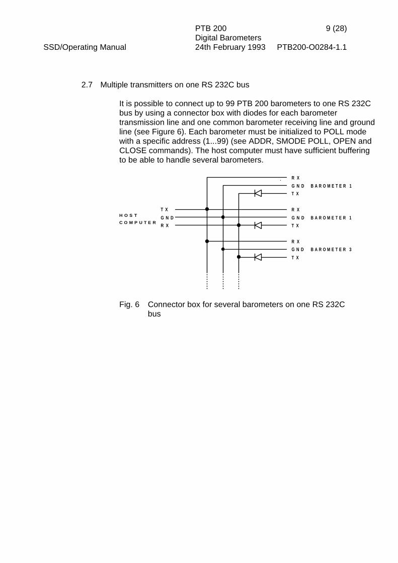
2.7 Multiple transmitters on one RS 232C bus
It is possible to connect up to 99 PTB 200 barometers to one RS 232Cbus by using a connector box with diodes for each barometertransmission line and one common barometer receiving line and groundline (see Figure 6). Each barometer must be initialized to POLL modewith a specific address (1...99) (see ADDR, SMODE POLL, OPEN andCLOSE commands). The host computer must have sufficient bufferingto be able to handle several barometers.
G N D
G N D
T X
R X
R X
G N D
T X
R X
G N D
T X
B A R O M E T E R 1
B A R O M E T E R 1
B A R O M E T E R 3
R X
T XH O S T
C O M P U T E R
Fig. 6 Connector box for several barometers on one RS 232Cbus

PTB 200 10 (28)Digital Barometers
SSD/Operating Manual 24th February 1993 PTB200-O0284-1.1
3 SERIAL COMMANDS
3.1 General
When delivered from factory the barometers are in serial full duplex RS232C mode. No handshaking lines are in use. All commands areechoed. The factory settings of the serial bus are:
baud rate 1200parity evendata bits 7stop bits 1echo ONsending mode STOPaddress 0
The following table briefly shows the configuration commands used tochange the settings of the PTB 200 barometers.
Function Command Commentserial bus settings SERIecho on/off ECHOoutput format FORMpressure resolution FORMunits UNITintegration time MTIM, FILTsettling time, responsetime
MTIM, FILT
sending mode SMODE STOP, RUN and POLLmodes
address ADDR for POLL mode onlysingle output command SCOM in STOP and RUN modes
onlysleep mode SLEEPlist of software settings ?
The default output format, pressure resolution and pressure unit havebeen set to fit meteorological requirements. The internal time constantsof the barometers have been chosen to prioritize short settling time(PTB 200 A: 2 s, PTB 201 A: 1 s) and high pressure resolution (PTB200 A: 0.01 hPa, PTB 201 A: 0.1 hPa). If longer settling time can beaccepted, use longer integration time to suppress noise effects.
PTB 200 11 (28)Digital Barometers
SSD/Operating Manual 24th February 1993 PTB200-O0284-1.1
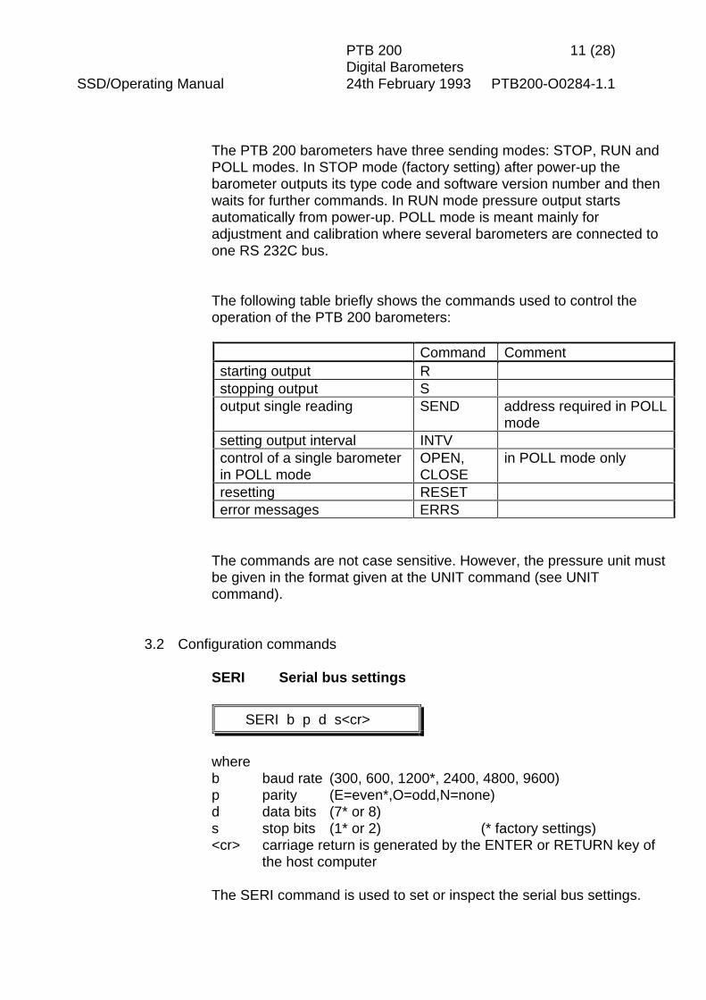
The PTB 200 barometers have three sending modes: STOP, RUN andPOLL modes. In STOP mode (factory setting) after power-up thebarometer outputs its type code and software version number and thenwaits for further commands. In RUN mode pressure output startsautomatically from power-up. POLL mode is meant mainly foradjustment and calibration where several barometers are connected toone RS 232C bus.
The following table briefly shows the commands used to control theoperation of the PTB 200 barometers:
Command Commentstarting output Rstopping output Soutput single reading SEND address required in POLL
modesetting output interval INTVcontrol of a single barometerin POLL mode
OPEN,CLOSE
in POLL mode only
resetting RESETerror messages ERRS
The commands are not case sensitive. However, the pressure unit mustbe given in the format given at the UNIT command (see UNITcommand).
3.2 Configuration commands
SERI Serial bus settings
SERI b p d s<cr>
whereb baud rate (300, 600, 1200*, 2400, 4800, 9600)p parity (E=even*,O=odd,N=none)d data bits (7* or 8)s stop bits (1* or 2) (* factory settings)<cr> carriage return is generated by the ENTER or RETURN key of
the host computer
The SERI command is used to set or inspect the serial bus settings.
PTB 200 12 (28)Digital Barometers
SSD/Operating Manual 24th February 1993 PTB200-O0284-1.1
Examples:>SERI<cr>1200 E 7 1
>SERI 9600 E 7 1<cr>9600 E 7 1>RESET<cr>
>SERI 1200<cr>1200 E 7 1>RESET<cr>
Always give the RESET command after the SERI command to invokethe new serial bus settings.
The following bus settings do not work with the barometer’s Intel 8051microprocessor and are modified by the barometer:
N 7 1 ⇒ N 7 2E 8 2 ⇒ E 8 1O 8 2 ⇒ O 8 1
Note: N 7 2 works on software version 1.06 or higher only.
The following settings can not be used at all:E 8 1, O 8 1
ECHO Setting the serial bus echo on/off
ECHO ON<cr>ECHO OFF<cr>
The ECHO command is used to control serial bus echo. In OFF modethe barometer does not output the ’>’ prompt character.
FORM Defining the output format
FORM<cr>
The FORM command is used to define the desired format and pressureresolution of the output. Do not use the FORM command to select apressure unit (instead see UNIT command).
PTB 200 13 (28)Digital Barometers
SSD/Operating Manual 24th February 1993 PTB200-O0284-1.1
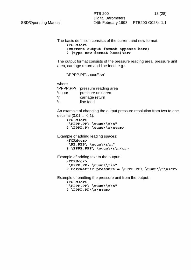
The basic definition consists of the current and new format:>FORM<cr>(current output format appears here)? (type new format here)<cr>
The output format consists of the pressure reading area, pressure unitarea, carriage return and line feed, e.g.:
"\PPPP.PP\ \uuuu\\r\n"
where\PPPP.PP\ pressure reading area\uuuu\ pressure unit area\r carriage return\n line feed
An example of changing the output pressure resolution from two to onedecimal (0.01 ⇒ 0.1):
>FORM<cr>"\PPPP.PP\ \uuuu\\r\n"? \PPPP.P\ \uuuu\\r\n<cr>
Example of adding leading spaces:>FORM<cr>"\PP.PPP\ \uuuu\\r\n"? \PPPP.PPP\ \uuuu\\r\n<cr>
Example of adding text to the output:>FORM<cr>"\PPPP.PP\ \uuuu\\r\n"? Barometric pressure = \PPPP.PP\ \uuuu\\r\n<cr>
Example of omitting the pressure unit from the output:>FORM<cr>"\PPPP.PP\ \uuuu\\r\n"? \PPPP.PP\\r\n<cr>
PTB 200 14 (28)Digital Barometers
SSD/Operating Manual 24th February 1993 PTB200-O0284-1.1
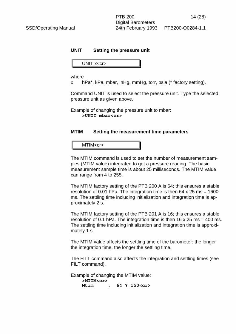
UNIT Setting the pressure unit
UNIT x<cr>
wherex hPa*, kPa, mbar, inHg, mmHg, torr, psia (* factory setting).
Command UNIT is used to select the pressure unit. Type the selectedpressure unit as given above.
Example of changing the pressure unit to mbar:>UNIT mbar<cr>
MTIM Setting the measurement time parameters
MTIM<cr>
The MTIM command is used to set the number of measurement sam-ples (MTIM value) integrated to get a pressure reading. The basicmeasurement sample time is about 25 milliseconds. The MTIM valuecan range from 4 to 255.
The MTIM factory setting of the PTB 200 A is 64; this ensures a stableresolution of 0.01 hPa. The integration time is then 64 x 25 ms = 1600ms. The settling time including initialization and integration time is ap-proximately 2 s.
The MTIM factory setting of the PTB 201 A is 16; this ensures a stableresolution of 0.1 hPa. The integration time is then 16 x 25 ms = 400 ms.The settling time including initialization and integration time is approxi-mately 1 s.
The MTIM value affects the settling time of the barometer: the longerthe integration time, the longer the settling time.
The FILT command also affects the integration and settling times (seeFILT command).
Example of changing the MTIM value:>MTIM<cr>Mtim : 64 ? 150<cr>

PTB 200 15 (28)Digital Barometers
SSD/Operating Manual 24th February 1993 PTB200-O0284-1.1
FILT Setting the filter parameters
FILT xxx yyyy<cr>
wherexxx ON or OFFyyyy FAST or SLOW
The FILT command is used to set additional numerical filtering modes.
FAST mode introduces a multiplication factor of 4 to the integration timeset with the MTIM command. In addition a special algorithm that takesthe derivative of the pressure change into account is used.
SLOW mode introduces a multiplication factor of 16 to the integrationtime set with the MTIM command. No derivative of the pressure changeis taken into account.
The filter settings also affect the settling time of the barometer.
Example of setting the integration time to 5 seconds (MTIM 50, filterFAST):
>MTIM<cr>Mtim : 64 ? 50<cr>>FILT ON FAST<cr>Press. filter : ON FAST
Example of setting the integration time to 60 seconds (MTIM 150, filterSLOW):
>MTIM<cr>Mtim : 50 ? 150<cr>>FILT ON SLOW<cr>Press. filter : ON SLOW
>FILT OFF<cr>turns the filter mode off. Then only the MTIM command affects the inte-gration and settling times.

PTB 200 16 (28)Digital Barometers
SSD/Operating Manual 24th February 1993 PTB200-O0284-1.1
SMODE Setting the sending mode
SMODE xxxx<cr> STOP and RUN modes onlySMODE aa STOP<cr> POLL mode only
wherexxxx STOP, RUN or POLLaa the address (1...99) of the barometer in the POLL mode
SMODE command sets or inspects the sending mode of the barometer.
The factory setting is the STOP mode. After power-up or reset the ba-rometer outputs only its type code and software version number;pressure readings are output only by command.
In the RUN mode the barometer starts to output pressure readingsautomatically after power-up or reset. The S command can be used tostop the output.
The POLL mode is used mainly during adjustment and calibration whenseveral barometers are connected to one RS 232C bus. In the POLLmode measurements can be output only with SEND aa command (seeSEND aa command). Echo is off in the POLL mode. See also OPENand CLOSE commands for further details on how to control a singlebarometer when several barometers are connected on one RS 232Cbus.
Example of setting, using and resetting the POLL mode:>SMODE<cr>Serial mode : STOP>ADDR<cr>Address : 0 ? 7<cr>>SMODE POLL<cr>Serial mode : POLLSEND 7<cr>(pressure reading appears here)SMODE 7 STOP<cr>Serial mode : STOP>ADDR<cr>Address : 7 ? 0<cr>

PTB 200 17 (28)Digital Barometers
SSD/Operating Manual 24th February 1993 PTB200-O0284-1.1
ADDR Setting the barometer address (for POLL mode only)
ADDR<cr>
ADDR is used to set or inspect an address (1...99) of a barometer forthe POLL mode.
Example of setting the address 7:>ADDR<cr>Address : 0 ? 7<cr>
A new address replaces the previous address. Always set the addressto 0 when no address is needed:
>ADDRAddress : 7 ? 0<cr>
If the barometer is not in the POLL mode, it will respond to any SENDcommand regardless of if there is an address or not. See SMODE andSEND commands for further details.
SCOM Setting a user defined command for single readingoutput (STOP and RUN modes only)
SCOM<cr>
is used to define a new command for single reading output in the STOPand RUN modes. A command defined by SCOM command does notwork in the POLL mode. The SEND command is always available.
Example of a command definition:>SCOM P<cr>>P<cr>(a single pressure reading appears)
A new SCOM command replaces the previous definition.
PTB 200 18 (28)Digital Barometers
SSD/Operating Manual 24th February 1993 PTB200-O0284-1.1
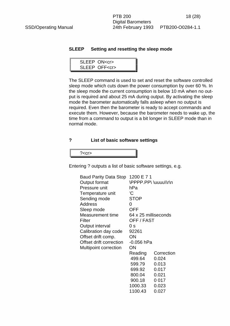
SLEEP Setting and resetting the sleep mode
SLEEP ON<cr>SLEEP OFF<cr>
The SLEEP command is used to set and reset the software controlledsleep mode which cuts down the power consumption by over 60 %. Inthe sleep mode the current consumption is below 10 mA when no out-put is required and about 25 mA during output. By activating the sleepmode the barometer automatically falls asleep when no output isrequired. Even then the barometer is ready to accept commands andexecute them. However, because the barometer needs to wake up, thetime from a command to output is a bit longer in SLEEP mode than innormal mode.
? List of basic software settings
?<cr>
Entering ? outputs a list of basic software settings, e.g.
Baud Parity Data Stop 1200 E 7 1Output format \PPPP.PP\ \uuuu\\r\nPressure unit hPaTemperature unit ’CSending mode STOPAddress 0Sleep mode OFFMeasurement time 64 x 25 millisecondsFilter OFF / FASTOutput interval 0 sCalibration day code 92261Offset drift comp. ONOffset drift correction -0.056 hPaMultipoint correction ON
Reading Correction 499.64 0.024 599.79 0.013 699.92 0.017 800.04 0.021 900.18 0 0171000.33 0.0231100.43 0.027
PTB 200 19 (28)Digital Barometers
SSD/Operating Manual 24th February 1993 PTB200-O0284-1.1
3.3 Operating commands
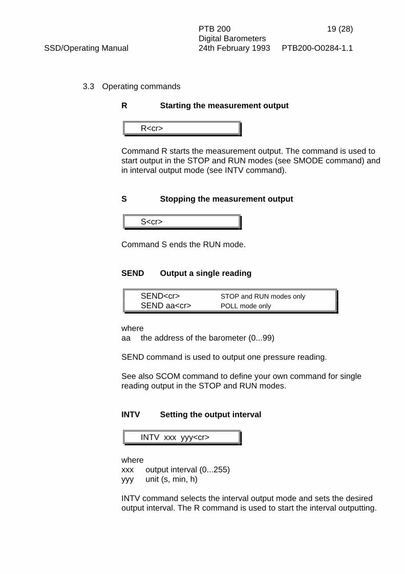
R Starting the measurement output
R<cr>
Command R starts the measurement output. The command is used tostart output in the STOP and RUN modes (see SMODE command) andin interval output mode (see INTV command).
S Stopping the measurement output
S<cr>
Command S ends the RUN mode.
SEND Output a single reading
SEND<cr> STOP and RUN modes onlySEND aa<cr> POLL mode only
whereaa the address of the barometer (0...99)
SEND command is used to output one pressure reading.
See also SCOM command to define your own command for singlereading output in the STOP and RUN modes.
INTV Setting the output interval
INTV xxx yyy<cr>
wherexxx output interval (0...255)yyy unit (s, min, h)
INTV command selects the interval output mode and sets the desiredoutput interval. The R command is used to start the interval outputting.

PTB 200 20 (28)Digital Barometers
SSD/Operating Manual 24th February 1993 PTB200-O0284-1.1
Example of outputting the current settings:>INTV<cr>Output intrv. : 0 s
Example of setting an output interval and starting outputting:>INTV 1 min<cr>Output intrv. : 1 min>R<cr>
Example of cancelling the interval output mode:>INTV 0 s<cr>Output intrv. : 0 s
OPEN Setting a barometer to STOP mode (POLL mode only,CLOSE software version 1.04 or higher)
OPEN aa<cr>CLOSE aa<cr>
whereaa the address (1 ... 99) of the barometer
OPEN and CLOSE commands are used to set a barometer momentar-ily to STOP mode and back to POLL mode again. This command isvery useful when several barometers are connected to one RS 232Cbus and only one individual barometer needs to be contacted.
Example of communication with a barometer with address 7:>OPEN 7<cr>PTB 7 bus opened for operator commands(normal commands can now be used without disturbing otherbarometers on the RS 232C bus)>CLOSE 7<cr>bus closed(the barometer with address 7 is set back to the POLL mode andonly SEND 7 and SMODE 7 STOP commands work)
Please note that when leaving the POLL mode, command CLOSE mustalways be followed by the address of the barometer.

PTB 200 21 (28)Digital Barometers
SSD/Operating Manual 24th February 1993 PTB200-O0284-1.1
RESET Resetting the barometer
RESET<cr>
resets the barometer. All software settings remain in the memory afterreset or any power failure. After changing the serial bus settingsRESET must always be given to invoke them.
ERRS Error message output
ERRS<cr>
ERRS command is used to print the error messages if any problemsoccur. The command outputs an error code and error description:
>ERRS<cr>E51 P y-value out of range
When an error occurs in the barometer, give the following seven com-mands and print the responses on paper. On the basis of the re-sponses to these commands Vaisala can quickly determine which ac-tions to take. The commands are:
>ERRS<cr>>?<cr>>C<cr>>F<cr>>T<cr>>Y<cr>>L<cr>
PTB 200 22 (28)Digital Barometers
SSD/Operating Manual 24th February 1993 PTB200-O0284-1.1
4 ADJUSTMENT AND CALIBRATION
The PTB 200 barometers can be adjusted and calibrated against localprimary standards that have high accuracy and stability as well asknown traceability to international standards.
The PTB 200 barometers are recommended to be adjusted orcalibrated once a year when used in automatic weather station applica-tions. In very demanding pressure standard applications shorter adjust-ment or calibration periods, e.g. two to four times a year, can bechosen.
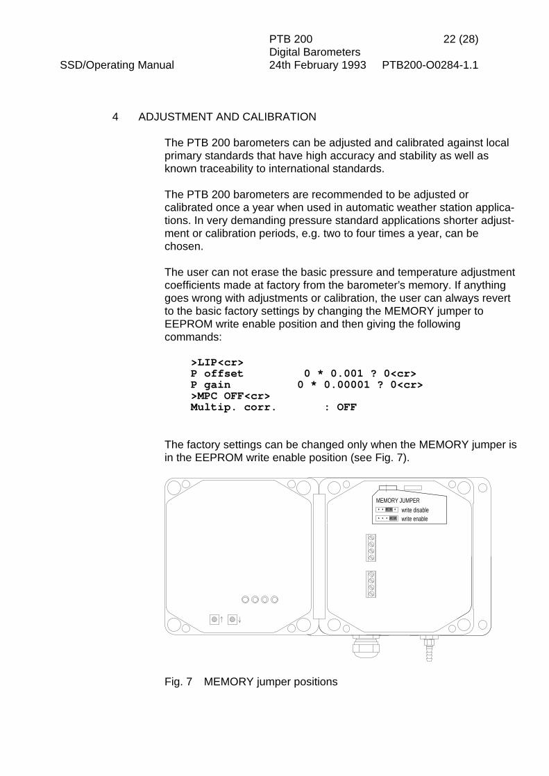
The user can not erase the basic pressure and temperature adjustmentcoefficients made at factory from the barometer’s memory. If anythinggoes wrong with adjustments or calibration, the user can always revertto the basic factory settings by changing the MEMORY jumper toEEPROM write enable position and then giving the followingcommands:
>LIP<cr>P offset 0 * 0.001 ? 0<cr>P gain 0 * 0.00001 ? 0<cr>>MPC OFF<cr>Multip. corr. : OFF
The factory settings can be changed only when the MEMORY jumper isin the EEPROM write enable position (see Fig. 7).
MEMORY JUMPERwrite disablewrite enable
Fig. 7 MEMORY jumper positions

PTB 200 23 (28)Digital Barometers
SSD/Operating Manual 24th February 1993 PTB200-O0284-1.1
The following pressure adjustments are possible:• offset adjustment• offset/gain adjustment• multipoint adjustment at up to eight pressure levels.
Offset and offset/gain adjustments are made with the barometerconnected to a reference pressure (see LP command). With the LPcommand the pressure value of the primary standard is given to the ba-rometer as a reference pressure and no separate corrections areneeded.
Before multipoint adjustment, the barometer must first be precalibratedin order to find out the corrections needed to bring the barometer to theaccuracy level of the primary standard. After precalibration themultipoint corrections are entered through the serial interface (see MPCand MPCI commands).
Note that up to 99 PTB 200 barometers can be connected to one RS232C bus which makes their adjustment and calibration more costeffective.
4.1 Offset and gain adjustment
LP Linear pressure adjustments
LP<cr>
The LP command is used in offset and offset/gain adjustment of thebarometer.
The offset adjustment can be made at any pressure level. To guaranteethe best possible pressure stability connect the pressure port of thebarometer to the pressure standard even during offset adjustment. Thetwo pressure levels used in offset/gain adjustment must be at least 400hPa apart.
Change the MEMORY jumper to the EEPROM write enable position.
Example of an offset adjustment:>LP<cr>Ref1 ? (set pressure level and enter valuehere)<cr>P : (the current non-corrected valueappears here)Ref2 ? <cr>

PTB 200 24 (28)Digital Barometers
SSD/Operating Manual 24th February 1993 PTB200-O0284-1.1
Example of an offset and gain adjustment:>LP<cr>Ref1 ? (set first pressure level and enter valuehere)<cr>P : (the current non-corrected valueappears here)Ref2 ? (set second pressure level and entervalue here)<cr>P : (the current non-corrected valueappears here)
Use ESC to abort without executing a command.
Return the MEMORY jumper to the EEPROM write disable position.
4.2 Multipoint pressure adjustment
MPC OFF Multipoint correction offMPCI Multipoint correction inputMPC ON Multipoint correction on
MPC OFF<cr>MPCI<cr>MPC ON<cr>
The MPC/MPCI commands are used in multipoint pressure adjustmentat up to eight pressure levels.
If a new fine adjustment is needed, the previous multipoint correctionsmust first be omitted with the MPC OFF command. Writing down theprevious multipoint corrections is recommended as they will be lostwhen MPCI command is used. Precalibrate the barometer to find outthe new multipoint corrections; the corrections are then entered usingthe MPCI command. The MPC ON command is used to activate thenew corrections.
Change the MEMORY jumper to the EEPROM write enable position.
Example of the multipoint pressure correction procedure:>LIP<cr>P offset 0 * 0.001 ? 0<cr>P gain 0 * 0.00001 ? 0<cr>>MPC OFF <cr>Multip. corr. : OFF
PTB 200 25 (28)Digital Barometers
SSD/Operating Manual 24th February 1993 PTB200-O0284-1.1
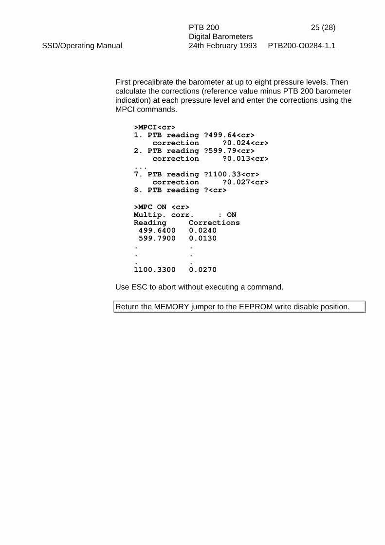
First precalibrate the barometer at up to eight pressure levels. Thencalculate the corrections (reference value minus PTB 200 barometerindication) at each pressure level and enter the corrections using theMPCI commands.
>MPCI<cr>1. PTB reading ?499.64<cr> correction ?0.024<cr>2. PTB reading ?599.79<cr> correction ?0.013<cr>...7. PTB reading ?1100.33<cr> correction ?0.027<cr>8. PTB reading ?<cr>
>MPC ON <cr>Multip. corr. : ONReading Corrections 499.6400 0.0240 599.7900 0.0130. .. .. .1100.3300 0.0270
Use ESC to abort without executing a command.
Return the MEMORY jumper to the EEPROM write disable position.
PTB 200 26 (28)Digital Barometers
SSD/Operating Manual 24th February 1993 PTB200-O0284-1.1
5 TECHNICAL DATA
OPERATING RANGE
Pressure range 600 ... 1100 hPaOperating temperature range -40 °C ... +60 °CStorage temperature range -60 °C ... +60 °CHumidity range non-condensing
Note: 1 hPa = 1 mbar (see note below).
ACCURACY PTB 200 A PTB 201 A
Linearity * ±0.05 hPa 1)
±0.10 hPa 2)±0.15 hPa
Hysteresis * ±0.03 hPa ±0.03 hPaRepeatability * ±0.03 hPa ±0.03 hPaCalibration uncertainty ** ±0.10 hPa ±0.20 hPaAccuracy at +20 °C *** ±0.12 hPa 1)
±0.15 hPa 2)±0.25 hPa
Temperature dependence ±0.1 hPa ±0.1 hPaTotal accuracy (RSS) ±0.20 hPa ±0.3 hPaLong-term stability ±0.1 hPa / a +0.2 hPa / a
* Defined as the ±2 standard deviation limits of end-point non-linearity, hysteresis error or repeatability error.
** Defined as ±2 standard deviation limits of inaccuracy of the pri-mary or working standard at 1000 hPa in comparison to interna-tional standards (NIST).
*** Defined as the root sum of the squares (RSS) of end-point non-linearity, hysteresis error, repeatability error and calibration uncer-tainty at room temperature.
1) 800 to 1100 hPa2) 600 to 1100 hPa
Note. The unit hectopascal (hPa) is recommended by WMO to beused in meteorological barometric pressure measurement (seeWMO Guide to Meteorological Instruments and Methods of Ob-servation, Fifth edition, 1983).
The official unit of pressure is pascal (Pa) and its multiplesaccording to the International System of Units (SI) andaccording to ISO 1000.
PTB 200 27 (28)Digital Barometers
SSD/Operating Manual 24th February 1993 PTB200-O0284-1.1
GENERAL CHARACTERISTICS (factory settings*)
Supply voltage 10 ... 30 VDC, polarity protectedSupply voltage sensitivity negligibleCurrent consumption < 25 mA
< 10 mA (sleep mode)< 0.1 mA (shutdown mode)
Serial I/O RS 232C* full duplex serial I/O orbidirectional TTL level serial I/O
code ASCIIparity even*, odd, nonedata bits 7* or 8stop bits 1* or 2
Pulse output pulse output at about 4.5 kHz;10.000 pulses = 1000.0 hPa
Pressure units hPa*, kPa, mbar, inHg, mmHg,torr, psia
Baud rates 300, 600, 1200*, 2400, 4800,9600
ResolutionPTB 200 A 0.01 hPa*PTB 201 A 0.1 hPa*
Settling time after power-upPTB 200 A 2 seconds*PTB 201 A 1 second*
Pressure step response timePTB 200 A 500 ms*PTB 201 A 300 ms*
Acceleration sensitivity negligiblePressure connection M5 (10-32) internal threadPressure fitting barbed tube for 1/8" I.D. tubingMaximum pressure limit 5000 hPa abs.Minimum pressure limit 0 hPa abs.Cable bushing for 5 ... 10 mm diameter cablesElectrical connections
excitation supply, GND, CTRL (forshutdown)
serial communication TX, RX, GNDpulse output PULSE, PULSE TRIG, GND
Electrical connectors screw terminals for AWG 22...16wire
Housing epoxy painted aluminiumWeight 950 g
PTB 200 28 (28)Digital Barometers
SSD/Operating Manual 24th February 1993 PTB200-O0284-1.1
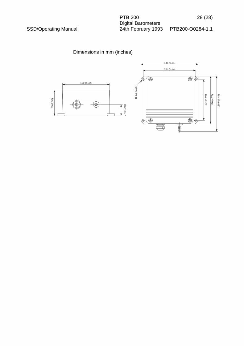
Dimensions in mm (inches)
27.5
(1.
08)
120 (4.72)
65 (
2.56
) Ø 6
.5 (
0.26
)
104
(4.0
9)
139.
5 (5
.49)
145 (5.71)
133 (5.24)
120
(4.7
2)

PTB200 Digital BarometerAppendix 1
1994-08-16 1
SERIAL COMMANDS
Function Command Commentserial bus settings SERIecho on/off ECHOoutput format FORMpressure resolution FORMunits UNITintegration time MTIM, FILTsettling time/response time MTIM, FILTsending mode SMODE STOP, RUN and POLL modesaddress ADDR for POLL mode onlydefining single outputcommand
SCOM in STOP and RUN modesonly
sleep mode SLEEPlist of software settings ?
starting output Rstopping output Soutput single reading SEND in POLL mode address
requiredsetting output interval INTVcontrol of a single barometerin POLL mode
OPEN ,CLOSE
resetting RESETerror messages ERRS
linear pressure adjustment LPmultipoint correction MPC, MPCI