PT3 Rotational Inspection and Alignment Procedure · PT3 Rotational Inspection and Alignment...
18
T T R R I I E E X X T T E E C C H H N N O O L L O O G G I I E E S S , , I I N N C C . . PT3 Rotational Inspection and Alignment Procedure Document No.: TR10955 Revision: 1.0 Date November 21, 2013
-
Upload
phungtuyen -
Category
Documents
-
view
226 -
download
3
Transcript of PT3 Rotational Inspection and Alignment Procedure · PT3 Rotational Inspection and Alignment...
TTTRRRIIIEEEXXX TTTEEECCCHHHNNNOOOLLLOOOGGGIIIEEESSS,,, IIINNNCCC...
PT3 Rotational Inspection and
Alignment Procedure
Document No.: TR10955 Revision: 1.0 Date November 21, 2013

Page 2
TTTRRRIIIEEEXXX TTTEEECCCHHHNNNOOOLLLOOOGGGIIIEEESSS,,, IIINNNCCC...
8030 Bracken Pl SE Snoqualmie, WA 98065
www.triextech.com
Revision History
Revision Version Date Author Description 1.0 11/20/2012 T.Ojalehto Created document

Page 3
TTTRRRIIIEEEXXX TTTEEECCCHHHNNNOOOLLLOOOGGGIIIEEESSS,,, IIINNNCCC...
8030 Bracken Pl SE Snoqualmie, WA 98065
www.triextech.com
Approvals
Troy Ojalehto Date
Tim Wright Date

Page 4
TTTRRRIIIEEEXXX TTTEEECCCHHHNNNOOOLLLOOOGGGIIIEEESSS,,, IIINNNCCC...
8030 Bracken Pl SE Snoqualmie, WA 98065
www.triextech.com
Table of Contents
1 Purpose ................................................................................................................................................. 5
2 Required Tools ...................................................................................................................................... 5
3 Concentricity Check .............................................................................................................................. 7
4 Adjustment.......................................................................................................................................... 12
5 Final Check .......................................................................................................................................... 18

Page 5
TTTRRRIIIEEEXXX TTTEEECCCHHHNNNOOOLLLOOOGGGIIIEEESSS,,, IIINNNCCC...
8030 Bracken Pl SE Snoqualmie, WA 98065
www.triextech.com
1 Purpose The purpose of this document is to provide a procedure for inspecting and adjusting the runout (concentricity) of the actuators to the R2 rotational axis as defined by the pinch hanger scale. This procedure addresses arc motion test failures due to misalignment of the actuator carriage caused by collisions of the actuator carriage or over-tightening of the Z axis locking wheel.
2 Required Tools
2.1 A 3mm Allen wrench:
Page 6
TTTRRRIIIEEEXXX TTTEEECCCHHHNNNOOOLLLOOOGGGIIIEEESSS,,, IIINNNCCC...
8030 Bracken Pl SE Snoqualmie, WA 98065
www.triextech.com
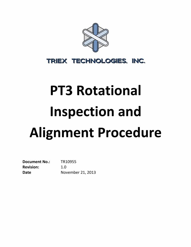
2.2 Dial Test Indicator such as Interapid No. 312b-1:
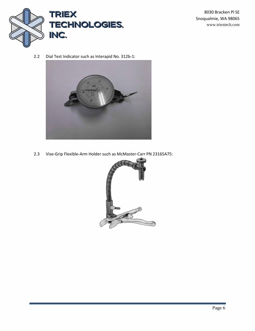
2.3 Vise-Grip Flexible-Arm Holder such as McMaster-Carr PN 23165A75:

Page 7
TTTRRRIIIEEEXXX TTTEEECCCHHHNNNOOOLLLOOOGGGIIIEEESSS,,, IIINNNCCC...
8030 Bracken Pl SE Snoqualmie, WA 98065
www.triextech.com
3 Concentricity Check 3.1 Place the PT3 on a large enough surface so that it may be turned around for access to front and
rear with no obstructions. 3.2 Fully retract the Z-Axis and loosen the locking wheel:
3.3 Place an actuator in the cross rail bracket and visually align it as close to center as possible, referencing the scribe marks on both sides of the cross rail bracket and the actuator attachment:

Page 8
TTTRRRIIIEEEXXX TTTEEECCCHHHNNNOOOLLLOOOGGGIIIEEESSS,,, IIINNNCCC...
8030 Bracken Pl SE Snoqualmie, WA 98065
www.triextech.com
3.4 Clamp the Vise-Grip Flexible-Arm Holder to the table using two pieces of cardboard to avoid damaging the table and install the indicator in the holder and position as shown:

Page 9
TTTRRRIIIEEEXXX TTTEEECCCHHHNNNOOOLLLOOOGGGIIIEEESSS,,, IIINNNCCC...
8030 Bracken Pl SE Snoqualmie, WA 98065
www.triextech.com
3.5 Align the indicator with the actuator shaft approximately as shown and adjust so the indicator is showing at least .03” (.75mm) of reading. The X, Y, and R1 axes can be moved as needed to position the indicator correctly. Once in the correct position the X and Y axes should be lightly secured for testing by gently tightening the lockscrews. Do not tighen the Z Axis lockscrew!
Page 10
TTTRRRIIIEEEXXX TTTEEECCCHHHNNNOOOLLLOOOGGGIIIEEESSS,,, IIINNNCCC...
8030 Bracken Pl SE Snoqualmie, WA 98065
www.triextech.com
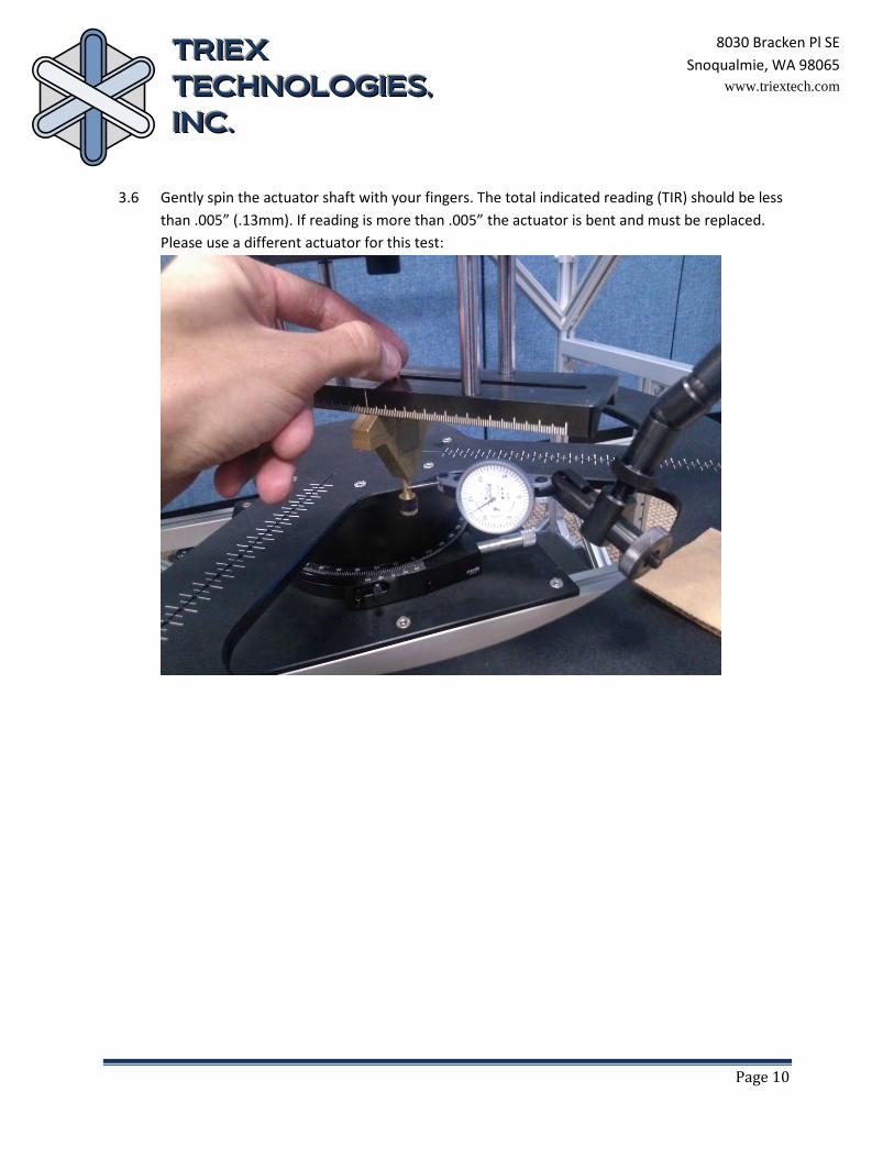
3.6 Gently spin the actuator shaft with your fingers. The total indicated reading (TIR) should be less than .005” (.13mm). If reading is more than .005” the actuator is bent and must be replaced. Please use a different actuator for this test:

Page 11
TTTRRRIIIEEEXXX TTTEEECCCHHHNNNOOOLLLOOOGGGIIIEEESSS,,, IIINNNCCC...
8030 Bracken Pl SE Snoqualmie, WA 98065
www.triextech.com
3.7 After actuator runout has been verified, check the actuator carriage concentricity by gently spinning the R2 axis rotation handle at least two full revolutions making sure the needle is staying in contact with the actuator through the full rotation (not running out of scale):
Page 12
TTTRRRIIIEEEXXX TTTEEECCCHHHNNNOOOLLLOOOGGGIIIEEESSS,,, IIINNNCCC...
8030 Bracken Pl SE Snoqualmie, WA 98065
www.triextech.com
3.8 If TIR is less than .03” (.75mm) your PT3 is properly aligned. If it is greater than .03” TIR please proceed to the next step.
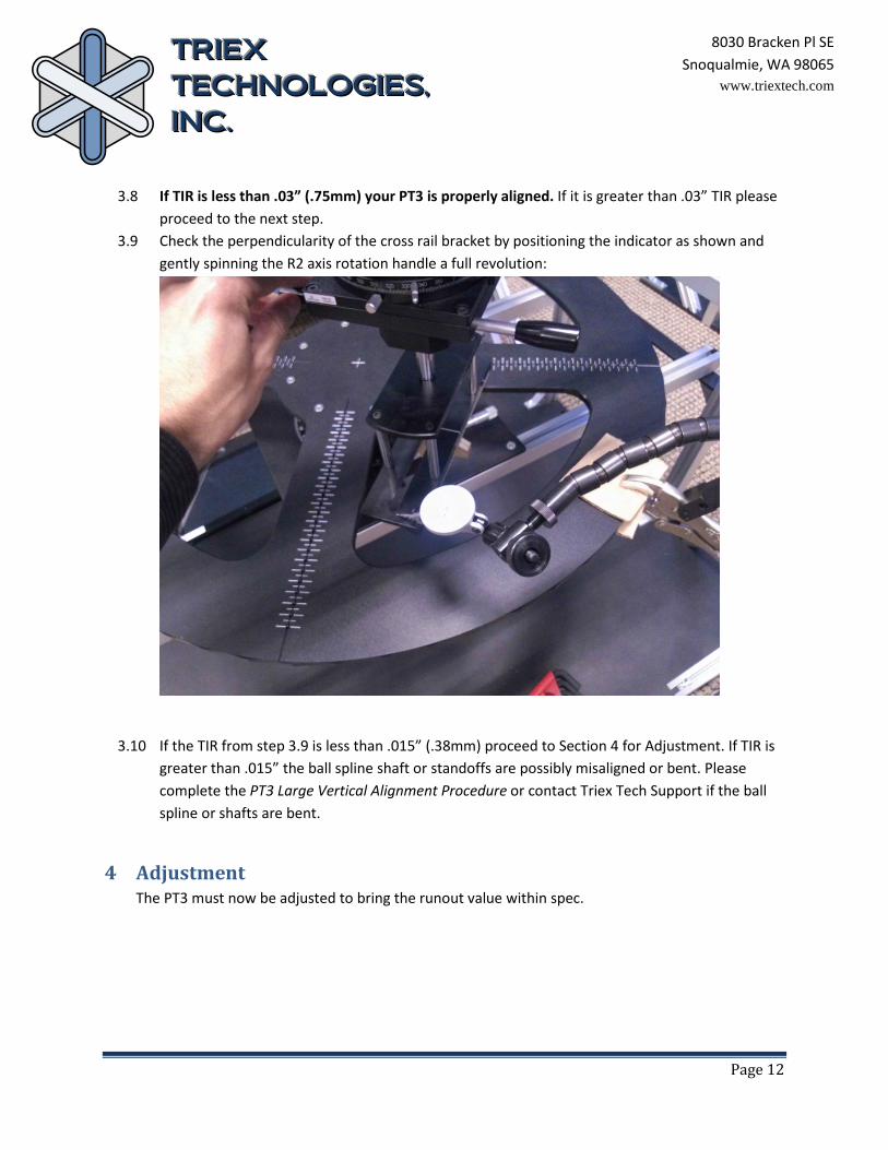
3.9 Check the perpendicularity of the cross rail bracket by positioning the indicator as shown and gently spinning the R2 axis rotation handle a full revolution:
3.10 If the TIR from step 3.9 is less than .015” (.38mm) proceed to Section 4 for Adjustment. If TIR is greater than .015” the ball spline shaft or standoffs are possibly misaligned or bent. Please complete the PT3 Large Vertical Alignment Procedure or contact Triex Tech Support if the ball spline or shafts are bent.
4 Adjustment The PT3 must now be adjusted to bring the runout value within spec.

Page 13
TTTRRRIIIEEEXXX TTTEEECCCHHHNNNOOOLLLOOOGGGIIIEEESSS,,, IIINNNCCC...
8030 Bracken Pl SE Snoqualmie, WA 98065
www.triextech.com
4.1 Slowly spin the R2 axis handles as in Section 3.7 but now observe the high and low indicator readings in relation to the rotational position of the cross rail bracket. Note the low point and position the rotation with the indicator reading at this low point:

Page 14
TTTRRRIIIEEEXXX TTTEEECCCHHHNNNOOOLLLOOOGGGIIIEEESSS,,, IIINNNCCC...
8030 Bracken Pl SE Snoqualmie, WA 98065
www.triextech.com
4.2 With the 3mm Allen Wrench loosen the 4 screws holding the axial block to the rotational stage until they are just loose enough to allow some movement but not so loose as to allow slop:

Page 15
TTTRRRIIIEEEXXX TTTEEECCCHHHNNNOOOLLLOOOGGGIIIEEESSS,,, IIINNNCCC...
8030 Bracken Pl SE Snoqualmie, WA 98065
www.triextech.com
4.3 Adjust the runout by placing your hands on the R2 rotation stage and axial block and carefully sliding the axial block towards you until the indicator reads half the amount of the TIR you originally indicated:

Page 16
TTTRRRIIIEEEXXX TTTEEECCCHHHNNNOOOLLLOOOGGGIIIEEESSS,,, IIINNNCCC...
8030 Bracken Pl SE Snoqualmie, WA 98065
www.triextech.com
4.4 Gripping only on the micrometer handle as shown, rotate a full revolution to verify that you have brought the system into alignment (.030” TIR max)

Page 17
TTTRRRIIIEEEXXX TTTEEECCCHHHNNNOOOLLLOOOGGGIIIEEESSS,,, IIINNNCCC...
8030 Bracken Pl SE Snoqualmie, WA 98065
www.triextech.com
4.5 Repeat steps 4.3 and 4.4 as needed until correct alignment is achieved. 4.6 Being careful not to bump any of the components you just aligned, use a 3mm Allen wrench to
lightly tighten the four screws holding the axial block to the rotational stage using an X pattern:
4.7 Repeat step 3.7 to verify runout did not change after tightening screws.

Page 18
TTTRRRIIIEEEXXX TTTEEECCCHHHNNNOOOLLLOOOGGGIIIEEESSS,,, IIINNNCCC...
8030 Bracken Pl SE Snoqualmie, WA 98065
www.triextech.com
5 Final Check Verify the following:
5.1 The X,Y, Z, R1, and R2 axes are unlocked.
5.2 The actuator carriage (R2 axis) rotates freely. If not, please refer to the PT3 Large Vertical Alignment Procedure.
5.3 The red handle on top moves the Z axis smoothly up and down and that the Z axis spring rolls and unrolls smoothly. If not, please refer to the PT3 Large Vertical Alignment Procedure.
5.4 The actuator carriage slides freely along the frame.