PT IP Camera - download.level1.infodownload.level1.info/manual/FCS-5043-V1_UM_V1.0.pdf · Network...
56
Network Camera User’s Manual 1/56 FCS-5043 Zoom Network camera, 2-Megapixel, Outdoor, 802.3af PoE, IR LEDs, Day & Night, 3x User Manual Version 1.0
Transcript of PT IP Camera - download.level1.infodownload.level1.info/manual/FCS-5043-V1_UM_V1.0.pdf · Network...

Network Camera Userrsquos Manual
156
FCS-5043
Zoom Network camera 2-Megapixel Outdoor 8023af PoE IR LEDs Day
amp Night 3x
User Manual
Version 10
Network Camera Userrsquos Manual
256
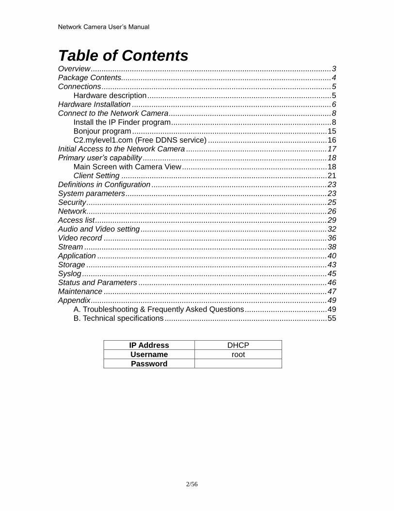
Table of Contents
Overview 3 Package Contents 4 Connections 5
Hardware description 5 Hardware Installation 6 Connect to the Network Camera 8
Install the IP Finder program 8 Bonjour program 15 C2mylevel1com (Free DDNS service) 16
Initial Access to the Network Camera 17 Primary userrsquos capability 18
Main Screen with Camera View 18 Client Setting 21
Definitions in Configuration 23 System parameters 23 Security 25 Network 26 Access list 29 Audio and Video setting 32 Video record 36 Stream 38 Application 40 Storage 43 Syslog 45 Status and Parameters 46 Maintenance 47 Appendix 49
A Troubleshooting amp Frequently Asked Questions 49 B Technical specifications 55
IP Address DHCP
Username root
Password
Network Camera Userrsquos Manual
356
Overview
Law in your country may prohibit the use of surveillance devices The Network Camera is not only a high-performance web-ready camera but also can be part of a flexible surveillance system It is the userrsquos responsibility to ensure that the operation of such devices is legal before installing this unit for its intended use It is important to first verify that all contents received are complete according to the list in the Package Contents chapter Take notice of the warnings in ldquoQuick installation guiderdquo before the Network Camera is installed then carefully read and follow the instructions in the ldquoInstallationrdquo chapter to avoid damages due to faulty assembly and installation This also ensures the product is used properly as intended The Network Camera is accessible via the LAN or Internet connection Connect your Network Camera directly to a computer network or DSL modem and with a standard Web browser you get instant on demand video streams Within minutes you can set up the Network Camera to capture a video sequence to a PC Live video image can be uploaded to a website for the world to see or made available only to select users on the network
The Network Camera is a network device and its use should be straightforward for those who have basic network knowledge The Network Camera is designed for various applications including video sharing general securitysurveillance etc The ldquoHow to Userdquo chapter suggests ways to best utilize the Network Camera and ensure proper operations
Minimum System Requirement
Zoom Network camera 2-Megapixel Outdoor 8023af PoE IR LEDs Day Network Environment
LAN 101001000M Ethernet
Monitoring System Recommended for Internet Explorer
System Hardware Basic requirements middot CPU Intelreg Celeronreg Dual-Core 270GHz or above middot Memory Size 2 GB or above Recommended middot VGA card resolution 1024 x 768 or above
System Requirement for Viewer amp Recorder Application
Support OS XP Windows 7
System Hardware 1-4 cameras surveillance application middot CPU Intelreg Celeronreg Dual-Core 270GHz or above middot Memory Size 2 GB or above middot VGA card resolution 1024 x 768 or above
Network Camera Userrsquos Manual
456
Package Contents
If any of the above items are missing please contact your dealer immediately
Note Using a power supply with a different voltage than the one included with the Network Camera will cause damage and void the warranty for this product
Network Camera (Wired or PoE)
Software CD
Power adapter
Quick installation guide
WrenchScrewsWall Mount Bracket
Moisture AbsorberRJ45 Female
Network Camera Userrsquos Manual
556
Connections
Hardware description
Plan view panel
Inner View
Network Camera Userrsquos Manual
656
Hardware Installation 1 Attach the Network Camera with the included stand
2 Place the Camera fix it onto ceiling or wall Use screws to fix the Network Camera onto the ceiling or wall
3 Power over Ethernet (PoE) Using a PoE-enabled switch The Network Camera is PoE-compliant allowing transmission of power and data via a single Ethernet cable Follow the below illustration to connect the Network Camera to a PoE-enabled switch via Ethernet cable
Network Camera Userrsquos Manual
756
General Connection (without PoE) 1 Connect the camera to a switch via Ethernet cable
2 Connect the power cable from the Network Camera to power outlet
4General IO Terminal Block This Network Camera provides a general IO terminal block which is used to connect external input devices The pin definitions are described below
Network Camera Userrsquos Manual
856
Connect to the Network Camera
Install the IP Finder program When you installed your Network camera on your LAN environment you may install ldquoIP Finderrdquo to discover Network camerarsquos IP address The Administrator must place the product software CD into the CD-ROM drive of the PC running in Microsoft Windows An auto-run program will pop up (If the program is not on auto-run go to the root directory of the software CD and click on ldquoautorunexerdquo)
Click on ldquoSoftware Utilityrdquo item after the window contents changed click on ldquoInstall IP Finderrdquo to run ldquoIP Finderrdquo program
Network Camera Userrsquos Manual
956
ldquoIP Finderrdquo is used to search the IP address of Network Cameras or Video servers on a LAN After searching Video Servers or Network Cameras will be located by the IP Finder
Network Camera Userrsquos Manual
1056
Search Camera
Click search Camera button the program will search for all family network devices on the same LAN After searching the main installer window will pop up Click on the MAC and model name which matches the product label on your device to connect to the Network Camera via Internet Explorer
Network Camera Userrsquos Manual
1156
Setup Camera Auto Install Wizard will be started and that it can auto guide through the installation process Press the ldquoNextrdquo button execute next process For more information please refer to the Network section on page 31
Network Camera Userrsquos Manual
1256
Network Camera Userrsquos Manual
1356
Network Camera Userrsquos Manual
1456
Network Camera Userrsquos Manual
1556
Bonjour program Safari browser supports Bonjour search program the will search for all family network devices on the same LAN
Network Camera Userrsquos Manual
1656
C2mylevel1com (Free DDNS service) 1 When you want to connect the network camera over Internet you can use the service ldquoC2mylevel1comrdquo The ldquoip-discoverycomrdquo is a free DDNS server for this camera Make sure that the router must start UPnP and DHCP server functions You can get the domain name which you wish very easily after registration In Network pagemdashDDNS settings of this camera you just input the host name you want and your e-mail address and click ldquoRegisterrdquo then you can have the hostname for this camera not longer than 20 seconds if the DDNS registration result is OK Then you can connect to this ip camera by httpXXXc2mylevel1com XXX the host name you type The HTTP port (get it automatically by c2mylevel1 server)
User password Default the password is last six number of the MAC To change ldquorootrdquo password at ldquoSecurity configurationrdquo can change the user password This ldquoUser passwordrdquo is entered in the c2mylevel1com Password Note You must set the ports between your router and camera manually if the registration is failed
Network Camera Userrsquos Manual
1756
Initial Access to the Network Camera
(1) For the initial access to the Network Camera in Windows the web browser may prompt for permission to install a new plug-in for the Network Camera This plug-in has been registered for certificate and is used to display the video in the browser
Users may click on to proceed
1 Click ldquoInstallrdquo and ldquoRunrdquo ActiveX controls 2 The video will be displayed
Network Camera Userrsquos Manual
1856
Primary userrsquos capability
Main Screen with Camera View The main page has three parts
1 Configuration functions The camera can be configured using these user interfaces
2 Connection control buttons These buttons provide the remote and local switching stream
3 Camera View What the camera sees Click the configuration in the bottom of left column to link to the configuration page
Configuration functions ldquoClient Settingsrdquo Clicking on this button links you to the client setting pages please check the following session for more details
ldquoConfigurationrdquo Please notes that only the administrator can access it ldquo Languagerdquo Click this button to choose a language for the user interface Language options are available in English traditional Chinese Simplified Chinese Japanese Spanish Portuguese French German Italiano
1
2
3
Network Camera Userrsquos Manual
1956
Camera view On the top of image shows the connecting type of the Network Camera and the current datetime
View capabilities
1 Click this button to capture and save still images The captured images will be
displayed in pop-up window Right-click the image and choose Save Picture As to save it in JPEG format
2 The button selection lets you open a digital zoom and to control the window to
enlarge a specified area in the camera view
3 Click this button to switch to full screen mode Press the ldquoEscrdquo key to switch back to normal mode
4 Click on this button freeze the video and playing when you click again
5 Click on this button stop video output
6 Use this functionyou can record video in your PC by browser directly The files
format will be in MP4
7 Click on this button adjust the audio volume amp Latency
8 Click on this button switch Mute OnOff
9 Click on this button to adjust the Function ldquo2-way audiordquo to be EnableDisable Enable this function request insert an external speaker The server can play sound from the client and receive sound from the environment and send to client
10 Click on this button to adjust the Microphone volume
Network Camera Userrsquos Manual
2056
11 Click on this button switch Microphone Mute OnOff Connection control buttons
1 ldquoConnectionrdquo User can choose Remote or Local mode for best connection quality Proposal Internet environment switch Remote mode
2 ldquoVideo Streamrdquo User can choose stream1 or stream2
Network Camera Userrsquos Manual
2156
Client Setting
1 ldquoIntranet Protocol Optionsrdquo Setting camera in intranet mode of protocol ldquoUDPrdquo Select use UDP protocol connect camera ldquoTCPrdquo Select use TCP protocol connect camera ldquoHTTPrdquo Select use HTTP protocol connect camera
2 ldquoInternet Protocol Optionsrdquo Setting camera in internet mode of protocol ldquoUDPrdquo Select use UDP protocol connect camera ldquoTCPrdquo Select use TCP protocol connect camera ldquoHTTPrdquo Select use HTTP protocol connect camera
3 ldquoRecording optionsrdquo Users can record live video as they are watching by
clicking start MP4 Recording on the main page Here you can specify the storage destination and file name
ldquoFolderrdquo Specify the storage destination for the recorded video files ldquoFile name prefixrdquo Enter the text that will be appended to the front of the video
file name ldquoAdd date and time suffix to file namerdquo Select this option to append the date
and time to the end of the file name
Network Camera Userrsquos Manual
2256
NOTEProtocol Options which allows choices on connection protocol between client and
server There are three protocols choices to optimize your usage ndash UDP TCP HTTP The UDP protocol allows for more real-time audio and video streams However some packets may be lost due to network burst traffic and images may be obscured The HTTP protocol allows for less packet loss and produces a more accurate video display The downside with this protocol is that the real-time effect is worse than that with the UDP protocol The TCP guarantees the complete delivery of streaming data and thus provides better video quality However the real-time effect is not as good as that of the UDP protocol If no special need is required UDP protocol is recommended Generally speaking the client choice will be in the order of UDP rarr HTTP After the Network Camera is connected successfully ldquoProtocol Optionrdquo will indicate the selected protocol The selected protocol will be recorded in the users PC and will be used for the next connection If the network environment is changed or the user wants to let the web browser to detect again manually select the UDP and TCP protocol save and return HOME to re-connect
Network Camera Userrsquos Manual
2356
Definitions in Configuration
Please note that only the Administrator can access the system configuration Each category in the left column will be explained on the following pages
System parameters
1 ldquoGeneral Settingrdquo
(1) ldquoHost namerdquo The text displays the title on the top of the main page
Firmware version
Network Camera Userrsquos Manual
2456
2 ldquoTime Settingrdquo (1) ldquoTime zonerdquo Choose a time zone from the down arrow
(2) ldquoDaylight savingrdquo For summertime It will be one hour ahead
(3) ldquoCurrent Timerdquo Network camera set the current time
(A) ldquoKeep current date and timerdquo Click on this to keep the current date and time of the Network Camera An internal real-time clock maintains the date and time even when the power of the system is turned off
(B) ldquoSync with computer timerdquo Synchronize the date and time in the Network Camera according to the local computer
(C) ldquoManualrdquo Adjust the date and time by the Administrator
(D) ldquoAdjust by NTP serverrdquo Synchronize the time according NTP server over the Internet whenever the Network Camera is switched on It fails if the assigned time-server cannot be found
(a) ldquoNTP serverrdquo Assign the IP address or domain name of the time-server Leaving the text box blank connects the Network Camera to the default time-servers
(b) ldquoUpdate intervalrdquo Select 0 ~ 23 hours update with the time on the NTP server
3 ldquoDI statusrdquo Please go to Application page for setting the DI
Network Camera Userrsquos Manual
2556
Security
Security setting The administrator account name is ldquorootrdquo which is permanent and can not be deleted If you want to add more accounts in the Manage User column please set a password for the ldquorootrdquo account first 1 ldquoChange root passwordrdquo Change the Administratorrsquos password by typing in the new password identically in both text boxes The typed entries will be displayed as asterisks for security purposes After pressing ldquofinishrdquo the web browser will ask the Administrator for the new password to access
2 ldquoManage privilegerdquo You can modify the manage privilege of operators or viewers Check or uncheck the item then click finish to enable the settings
3 ldquoManage userrdquo (1) ldquoAdd a new userrdquo Administrators can add up to 20 user accounts
(A) Input the new userrsquos name and password (B) Select the privilege level for the new user account Click Finish to enable the
setting
(2) ldquoDelete a userrdquo Select an existing user name Click Finish to enable the setting
Network Camera Userrsquos Manual
2656
(3) ldquoUpdate a existing userrdquo Select an existing user name Administrators can modify userrsquos password and privilege Click Finish to enable the setting
Access rights are sorted by user privilege (Administrator Operator and Viewer) Only administrators can access the Configuration page Operators cannot access the Configuration page but can use the URL Commands to get and set the value of parameters Viewers access only the main page for live viewing
Network
Any changes made on this page will restart the system in order to validate the changes Make sure every field is entered correctly before clicking on ldquofinishrdquo
Network Camera Userrsquos Manual
2756
Network Setting ldquoLANrdquo amp ldquoPPPoErdquo The default type is LAN Select PPPoE if using ADSL
1 LAN
The default status is Get IP address automatically This could be tedious to perform software installation whenever the Network Camera starts Therefore once the network is set especially for the IP address should be entered correctly Select Use fixed IP address then the Network Camera will skip installation The Network Camera will automatically restart and operate normally after a power outage You can run IP installer to check the IP address assigned to the Network Camera if the IP address is forgotten or you can use the UPnP function provided by the Network Camera (MS Windows XP provides UPnP function at My Network Place)
(1) ldquoGet IP address automaticallyrdquo (2) ldquoUse fixed IP addressrdquo
- ldquoIP addressrdquo This is necessary for network identification - ldquoSubnet maskrdquo This is used to determine if the destination is in the same subnet The default value is ldquo2552552550rdquo - ldquoDefault routerrdquo This is a gateway used to forward frames to destinations in a different subnet Invalid router setting will fail the transmission to destinations in different subnet - ldquoPrimary DNSrdquo The primary domain name server that translates hostnames into IP addresses - ldquoSecondary DNSrdquo Secondary domain name server backups the Primary DNS - ldquoEnable UPnP presentation amp port forwardingrdquo Enable UPnP ability - ldquoHttp portrdquo This can be typed besides the default Port 80 Once the port is changed the users must make sure the change for the connection is successful For instance when the Administrator changes the HTTP port of the Network Camera which IP address is 192168020 from 80 or 1025 to 65535 the users must type in the web browser ldquohttp1921680208080rdquo instead of ldquohttp192168020rdquo
- ldquoRTSP Portrdquo RTSP port can be typed besides the default Port 554 - ldquoRTP Portrdquo The RTP port can be typed besides the default Port 54
Note Please set Video RTP port in even number after default value port 54 Then
Video RTCP potAudio RTP portAudio RTCP port will automatically set the
values in ascending
- ldquoRTSP Streaming access namesrdquo The RTSP streaming currently supports video only audio only and audiovideo To use the audiovideo stream type the URL asldquortsp613012543liveNsdprdquo
2 PPPoE If using the PPPoE interface you should fill the following settings from ISP
(1) ldquoUser namerdquo The login name of PPPoE account (2) ldquoPasswordrdquo The password of PPPoE account (3) ldquoConfirm passwordrdquo Input password again for confirmation
Network Camera Userrsquos Manual
2856
DDNS Setting 1 ldquoEnable DDNSrdquo This option turns on the DDNS function
2 ldquoip-discoveryrdquo In the Register column fill in the Host name (xxxx ip-discovery) Email Key and Confirm Key then click Register After a host name has been successfully created a success message will be displayed in the DDNS Registration Result column and messaging E-mail
3 ldquo3rd party DDNSrdquo This is enable or disable 3rd party DDNS 4 ldquoProviderrdquo The provider list contains hosts that provide DDNS services Please connect to the service providerrsquos website to make sure the service charges
5 ldquoHost Namerdquo If the User wants to use DDNS service this field must be filled Please input the hostname that is registered in the DDNS server
6 ldquoUser namerdquo The Username or E-mail field is necessary for logging in the DDNS server or notify the User of the new IP address Note when this field is input as ldquoUser namerdquo the following field must be input as ldquoPasswordrdquo
7 ldquoPasswordrdquo Please input the password or key to get the DDNS service
8 ldquofinishrdquo Click on this button to save modify settings for the DDNS service
Network Camera Userrsquos Manual
2956
Access list
Access list setting 1 How to control access permission by verifying the client PCrsquos IP
address General Settings General Settings
Add a rule to configure an AllowedDenied list Click Add to add a rule
Network Camera Userrsquos Manual
3056
to AllowedDenied list There are three types of rules for user to set up ldquoSinglerdquo This rule allows the user to add an IP address to the AllowedDenied list For example
ldquoNetworkrdquo This rule allows the user to assign a network address and corresponding subnet mask to the AllowDeny List The IP address is written in the CIDR format For example
Network Camera Userrsquos Manual
3156
ldquoRangerdquo This rule allows the user to assign a range of IP addresses to the AllowDeny List This rule is only applied to IPv4 For example
Network Camera Userrsquos Manual
3256
Audio and Video setting
Network Camera Userrsquos Manual
3356
General Setting 1 ldquoColor moderdquo Select use color or monochrome video display
2 ldquoVideo orientationrdquo The orientation of video
(1) ldquoFliprdquo Vertically rotate the video
(2) ldquoMirrorrdquo Horizontally rotates the video
3 ldquoEnvironmentrdquo The orientation of video
(1) ldquoindoorrdquo This option is usually selected when the Network Camera is placed in indoor environments
(2) ldquooutdoorrdquo This option is usually selected when the Network Camera is placed in outdoor environments
4 ldquoPower freqrdquo Select 50 Hz or 60Hz power line frequency
The fluorescent light will flash according to the power line frequency that
depends on local utility Change the frequency setting to eliminate uncomfortable flash image when the light source is only fluorescent light
Video Setting 1 ldquoContrastrdquo Adjust the image contrast level which ranges from -5 to +5 The default value is set to 0
2 ldquoBrightnessrdquo Adjust the image brightness level which ranges from -5 to +5 The default value is set to 0
3 ldquoSaturationrdquo Adjust the image saturation level which ranges from -5 to +5 The default value is set to 0
4 ldquoSharpnessrdquo Adjust the image sharpness level which ranges from -5 to +5 The default value is set to 0
5 ldquoEVrdquo Exposure value represent the expected target value of the luminance of
the weighting result of AE windows in the image and its tolerance as offset
6 ldquoGainrdquo In the slide bar of Gain there are also two sliders which represent the
limitations to control the maximum gain value and the minimum one respectively Normally the minimum value is to 1x for better quality
Network Camera Userrsquos Manual
3456
Exposure setting Here it provides 3 mode Auto Backlight and Customized Auto and
Backlight modes are 2 default settings for general purpose and backlight scene
respectively
Customized mode relates to the grid window above can be pointed on for
interesting areas Within the mode Customized 1615 grids windows can be chosen to match wherewhat you are interested in Push down left-button of mouse and drag to draw the grids for interesting areas or push down right-button of mouse and drag to clean the grids for insignificant areas
ldquoTarget Luminance and Offsetrdquo
These two slide bar Target Luminance and Offset represent the expected
target value of the luminance of the weighting result of AE windows in the image and its tolerance as offset For example target luminance is set to 100 and target offset is set to 20 that means the average luminance of the AE window should be in the range from 80 to 120 (100plusmn(10 When the actual luminance does not meet this range the AE function will adjust shutter and gain to meet it as possible In some extreme cases it cannot reach the target because the environment is too bright or dark When the environment is not consistent eg with big moving objects and the offset is too narrow the AE will act more frequently that will cause the background of view inconsistent The offset value is recommended to set 15~25 of target luminance
Network Camera Userrsquos Manual
3556
ldquoGainrdquo
In the slide bar of Gain there are also two sliders which represent the limitations
to control the maximum gain value and the minimum one respectively Normally the minimum value is to 1x for better quality It is not allowed if the maximum slider and the minimum one are set to the same value without adjustable interval Besides the noise will be increased if the actual gain is too large When the max slider is dragged over sensors max gain the slide bar will become deep blue to represent it will apply Mozart 3s digital gain which extend the max gain for very low light
ldquoShutter Speedrdquo
There are 2 fields minimal and maximal time for the range of Shutter Speed
The precision of the parameter is 11000000 sec but it is NOT actual precision of the shutter speed of the sensor The actual precision of the shutter speed depends on each sensorrsquos specification Here it will be rounded to approach sensorrsquos effective exposure time To avoid flickering or banding phenomenon under fluorescent light the actual shutter speed will be locked at 1120 160
130 if Power Line Frequency is 60Hz or 1100 150 125 if Power Line
Frequency is 50Hz The setting of Power Line Frequency is on the sub-tab Video
and Audio The exposure may not be stable if the maximum value and the minimum one are set to the same value without adjustable interval Besides the frame rate will drop down if the actual shutter speed is too slow to meet expected frame rate
Noise reduction
Provides 2D and 3D features
Wide Dynamic Range Enable Wide Dynamic Range auto in different level to improve the exposure when both bright and dark areas simultaneously in the field of view of the camera The default is off
Infrared Led Setting 1 ldquoInfrared LED Controlrdquo IR led for Day and Night (Option) User can turn onoff the built-in IR led This function is very useful under low illumination environment
(1) ldquoAutordquo Select IR sensitivity from 0 to 4
(2) ldquoManualrdquo Turn onoff the IR led manually
- ldquoTurn onrdquo Turn on led - ldquoTurn offrdquo Turn off led
2 ldquoLow lux moderdquo The video quality will be improved when the camera is in low lux environment (1) ldquoDisable dark moderdquo Disable low lux mode
(2) ldquoEnable dark moderdquo Enable low lux mode
Network Camera Userrsquos Manual
3656
Video output Setting 1 ldquovideo outputrdquo Can switch between NTSC and PAL
Audio Setting 1 ldquoMuterdquo Audio mute
2 ldquoMicrophone rdquo External microphone
3 ldquoMic Volumerdquo Adjust microphone volume which ranges from 1 to 46
Video record
Schedule mode
(1) ldquoEvery dayrdquo EnableDisable every day application
(2) ldquoWeek dayrdquo EnableDisable week day application
(3)ldquoSelected dayrdquo EnableDisable selected day application
Schedule information
(1) Enter the ldquoStart timerdquo and ldquoStop timerdquo for day mode Note that the time format is [hhmm] and is expressed in 24-hour clock time By default the start and end time of day mode are set to 010000 and 235959
Network Camera Userrsquos Manual
3756
(2)ldquoSunrdquoldquoMonrdquoldquoTuerdquoldquoWedrdquoldquoThurdquoldquoFrirdquoldquoSatrdquo Select the days of the week to perform the application
(3) ldquoStart dayrdquo and ldquoStart timerdquo as the start timing the time ldquoEnd dayrdquo and ldquoEnd timerdquo as the end timing the time
(4) ldquoEnable cyclic recordingrdquo The cyclic recording function is enabled during the transaction stage when a storage space is full and the incoming streaming data is about to overwrite the previously saved videos
Record parameters (1)Source Select a stream for the recording source
(2)Recording interval Select the recording time interval
(3)Prefix file name You can setting the file name and enable or disable to add the date and time on file name
Response mode There are two choices of server types available NAS SD Card Select the item to display the detailed configuration options
(1)rdquoNASrdquo
--ldquoNAS server addressrdquo Enter IP address of the NAS server
--ldquoNAS shared directoryrdquo Enter the NAS shared directory path --ldquoWorkgrouprdquo Enter the NAS workgroup parameter --ldquoUser accountrdquo Enter the login name of the NAS account --ldquoUser passwordrdquo Enter the password of the NAS account Note Video record with the Application must be set to the same shared directory
path If you would like do detail recording settings or multi-channel recording please install bundled 64CH recording software in CD
Network Camera Userrsquos Manual
3856
Stream
Audio codec setting
(1)ldquoAudio codec typerdquo There are two choices of audio codec types
available rdquoAMRrdquo ldquoAACrdquo and rdquoG711rdquo
(2) ldquoBit raterdquo -- ldquoAMRrdquo The bit rates are selectable at the following rates
47505150590067007400795010200 and 12200
-- ldquoAACrdquo The bit rates are selectable at the following rates 8Kbps16Kbps 24Kbps and 32Kbps
-- ldquoG711rdquo pcmu and pcma
Video codec setting (1) ldquoSelect Streamrdquo The Network Camera supports ldquoStream 1rdquoand ldquoStream 2rdquo
(2) ldquoVideo codecrdquo The Network Camera supports three kind of video compression mode ldquoH264rdquo or ldquoMPEG4rdquo or ldquoMJPEGrdquo User can choose one of
Network Camera Userrsquos Manual
3956
these compression modes based on requirement or application
(3) ldquoVideo sizerdquo Click the down arrow to choose the quality of image (1920x1080 1280x1024 1280x800 640x480 320x240 176x144)
(4) ldquoConnection typerdquo User can select this button to choose the better video amp links quality (Internet mode or Intranet mode)
(5) ldquoFrame raterdquo This limits the maximal refresh frame rate per second Set the frame rate higher for a smoother video quality
(6) ldquoIntra frame periodrdquo Determine how often to plant an ldquoI framerdquo The shorter the duration the more likely you will get a better video quality but at the cost of higher network bandwidth consumption
(7) ldquoVideo Quality typerdquo Setting optimizes bandwidth utilization and video quality
-- ldquoConstant bit raterdquo User can adjust the video quality from 20 Kbps to 12 Mbps
-- ldquoFixed qualityrdquo user can select from lowest quality to get best quality according The ldquoQualityrdquo are selectable at the following rates From 1 to 20
Snapshot and time display setting Adjust the photo size specifications and choose whether to mark time on the video and photo
Network Camera Userrsquos Manual
4056
Application
Schedule mode
(1) ldquoEvery dayrdquo EnableDisable every day application
(2) ldquoWeek dayrdquo EnableDisable week day application
(3) ldquoSelected dayrdquo EnableDisable selected day application
Schedule information (1) Enter the ldquoStart timerdquo and ldquoStop timerdquo for day mode
Note that the time format is [hhmmss] and is expressed in 24-hour clock time By default the start and end time of day mode are set to 010000 and 235959
(2) ldquoSunrdquoldquoMonrdquoldquoTuerdquoldquoWedrdquoldquoThurdquoldquoFrirdquoldquoSatrdquo Select the days of the week to perform the application
(3) ldquoStart dayrdquo and ldquoStart timerdquo as the start timing the time ldquoEnd dayrdquo and ldquoEnd timerdquo as the end timing the time
Trigger mode
(1) ldquoVideo motion detectionrdquo EnableDisable video motion application (2) ldquoPeriodicallyrdquo This option allows the Network Camera to trigger
periodically for every other defined minute
Network Camera Userrsquos Manual
4156
(3) ldquoDigital inputrdquo This option allows the Network Camera to use an external digital input device or sensor as a trigger source Depending on your application there are many choices of digital input devices on the market which helps to detect changes in temperature vibration sound and light etc
parameters
(1) ldquoMotion parametersrdquo Higher sensitivity and small threshold will allow easier motion detection
(2) ldquoPeriod parametersrdquo This option allows the Network Camera to trigger periodically for every other defined seconds Up to 999 seconds are allowed
(3) ldquoDigital input parametersrdquo Select the digital input type and set trigger time
Media mode There are four choices of media types available ldquoSnapshotrdquo ldquoMessagerdquo ldquoRecord(Motion Detection only)rdquo and ldquoSystem logrdquo
Snapshot amp Record file setting You can setting the file name and enable or disable to add the date and time on file name Can setting the digital output duration seconds Response mode There are four choices of server types available Email FTP NAS and SD Card storage Select the item to display the detailed configuration options
(1)ldquoEmailrdquo -- ldquoEmail security moderdquo If your SMTP server requires a secure connection (SSL or TLS) check This server requires a secure connection (SSL or TLS) -- ldquoSender emailrdquo address Enter the email address of the sender -- ldquoRecipient emailrdquo address Enter the email address of the recipient
-- ldquoServer addressrdquo Enter the domain name or IP address of the email server
--ldquoUser namerdquo Enter the user name of the email account if necessary
--ldquoPasswordrdquo Enter the password of the email account if necessary
--ldquoServer portrdquo The default mail server port is set to 25 You can also manually set another port
(2)rdquoFTPrdquo -- ldquoServer addressrdquo Enter the domain name or IP address of the FTP server
-- ldquoServer portrdquo By default the FTP server port is set to 21
-- ldquoUser namerdquo Enter the login name of the FTP account
-- ldquoPasswordrdquo Enter the password of the FTP account
-- ldquoFTP folder namerdquo Enter the folder where the media file will be placed If the folder name does not exist the Network Camera will create one on the FTP server
(3)rdquoHTTP rdquo
-- ldquoURLrdquo Enter the URL of the HTTP server
-- ldquoUser accountrdquo Enter the user name if necessary -- ldquoUser passwordrdquo Enter the password if necessary
(4)rdquoNASrdquo --ldquoNAS server addressrdquo Enter IP address of the NAS server
--ldquoNAS shared directoryrdquo Enter the NAS shared directory path
Network Camera Userrsquos Manual
4256
--ldquoWorkgrouprdquo Enter the NAS workgroup parameter --ldquoUser accountrdquo Enter the login name of the NAS account --ldquoUser passwordrdquo Enter the password of the NAS account Note Video record with the Application must be set to the same shared directory
path If you would like do detail recording settings or multi-channel recording please install bundled 64CH recording software in CD
Network Camera Userrsquos Manual
4356
Storage
Manage the storage device
S torage Status Here show the storage device information
NAS server setting
1
2
3
Network Camera Userrsquos Manual
4456
(1) ldquoNAS Host namerdquo Choose and input the NAS Host name of this camera
(2) ldquoWorkgrouprdquo Input the name of Workgroup You can see the NAS Host name you input in the same workgroup with your PC Then you can connect to this device and download the files easily from SD card which is inserted to this camera
File operation Move the mouse over the file Press the mouse right button that Right-click menu is displayed You can delete files Move the mouse over the directory Press the mouse left button that the file structure expand Press the mouse right button that Right-click menu is displayed You can choose upload or delete files NOTEAllow the user to upload or delete files when the storage device is not write-
protected If the SD card canrsquot be detected please link to the following URL httpwwwsdcardorgconsumersformatter to download the ldquoSD Formatter Kitrdquo formatting your SD card
Network Camera Userrsquos Manual
4556
Syslog
The Network camera supports log the system messages on remote server The protocol is compliant to RFC 3164 If you have external Linux server with sys log service use ldquo-rrdquo option to turn on the facility for receiving log from remote machine Or you can use some software on Windows that is compliant to RFC 3164 An example is Kiwi Syslog Daemon Visit httpwwwkiwisyslogcomkiwi-syslog-daemon-overview Check ldquoSetuprdquo and ldquoEnablerdquo then input the ldquoIP addressrdquo and ldquoportrdquo number of the log server to enable the remote log facility In the ldquoCurrent logrdquo it displays the current system log file The content of the log provides useful information about configuration and connection after system boot- up
ldquofinishrdquo Click on this button to save modify settings
Network Camera Userrsquos Manual
4656
Status and Parameters
User can find a lot of information about the system such as ldquoUpnp port forwardingrdquo
ldquoTraversing NATrdquo ldquoPublic IPrdquo and so on User also can get the number of current viewer of the Network Camera here
Network Camera Userrsquos Manual
4756
Maintenance
1 ldquoReboot systemrdquo The ldquoRebootrdquo button will reboot the Network Camera Itrsquos useful while the Network Camera got problem 2 ldquoRestore systemrdquo Click on ldquoRestorerdquo button on the configuration page to restore the factory default settings Restore all settings to factory default except settings in ldquoNetwork type rdquo and ldquoRoot Passwordrdquo The system will restart and require the installer program to set up the network again
3 ldquoCalibraterdquo Recalibrate the auto focus position to the default range to recover the tolerance caused by some external forces 4 ldquoExportImport filerdquo -- Export setting backup file Click to export all parameters for the device and user-defined scripts
-- Upload setting backup file Click Browsehellip to upload a setting backup file Please note that the model and firmware version of the device should be the same as the setting backup file If you have set up a fixed IP or other special settings for your device it is not suggested to upload a settings backup file
4 ldquoUpgrade firmwarerdquo Select the firmware file and click upgrade button Please be aware that you should not turn off the power during updating the firmware and wait for finish message
Network Camera Userrsquos Manual
4856
Warning The upgrade firmware procedure cannot be interrupted If the power
andor network connection are broken during the procedure it might possibly cause serious damage to the Network Camera
Note When upgrade firmware please wait for 120~210 seconds and then you can connect to Network Camera again The system will restart and require the installer program to set up the network again
Network Camera Userrsquos Manual
4956
Appendix
A Troubleshooting amp Frequently Asked Questions Q1 Status led does not light up
A1 First make sure that「ConfigurationgtSystemgtTurn off the LED indicator」is disabled
If it is check the item and the led should light up Second if red led does not light up please check that the power adapter in the package is plugged correctly And last if green led does not light up please check that category 5 UTP cable is plugged correctly If the problem is still not solved please contact your dealer for further help
Q2 What kind of Ethernet cable is used by network camera
A2 The network Camera uses Category 5 UTP cable allowing 10 andor 100 Base-T networking
Q3 The Network Camera will be installed and work if a firewall exists on
the network
A3 There are two way to set up the IP camera at Internet (1) By UPnP Port Forwarding 1 Select an IP router It must support UPnP port forwarding and enable this function
first
2 Connect camera RJ45 cable to IP router and the router is also connected to Internet
3 Plug power cord to camera
4 Go to camera Network page Enable UPnP port forwarding
5 Check camera status we can see the ports had been successfully opened
Network Camera Userrsquos Manual
5056
6Type IP address8080 at browser Then you can see camera through Internet
7You can also type the ddns name at below label of camera on browser URL field For example you may type ah00001ip-discoverycom8080 (2) By Setting Port Forwarding Manually 1 Select a router Set the port forwarding as following
Network Camera Userrsquos Manual
5156
PS Port 80 is HTTP Port port 53 is stream port port 554 is RTSP port and port 443 is HTTPS port 2Go to camera Network page Disable UPnP port forwarding function
Network Camera Userrsquos Manual
5256
3 Type IP address at browser Then you can see camera through Internet
4 You can also type the ddns name at below label of camera on browser URL field For example you may type ah00001ip-discoverycom
Note The firewall software at PC may block the transfer of network camera Please remove or stop the kind software
Q4 How can I find the network camera in the local area network
A4 By using the IP Finder2 program or using UPnP to find it
Q5 IP Finder2 program cannot find Network Camera in the local area
network at first time
A5 Make sure the subnet of network camera is same as your PC If the local area network supports DHCP the camera is ldquoGet IP address automaticallyrdquo in the ldquoNetworkrdquo page default If the local area network does not support DHCP change your PC IP address to ldquo1921680xxxrdquo
Network Camera Userrsquos Manual
5356
Q6 How can I restore the network camera to default value
A6 Use a gem clip to press on the inside button Network camera begins to restore default value You can also press the button ldquoFactoryrdquo in ldquoMaintenancerdquo page to restore the default value
Q7 I cannot play the recorded video file
A7 Install the audio codec in the CD and use the Windows Media Player 10 or later to play the ASF or AVI file recorded by the network camera
Q8 Infrared led does not light up
A8 Check「ConfigurationgtAudio and VideogtInfrared LED Control」 is ldquoAutordquo or
ldquoManual》Turn onrdquo
Q9 The network camera cannot focus accurately
A9 (1) The lens is dirty or dust is attached Clean the lens with lens cleaner And then adjust the camera focus manually (2) The image may be out of focus If the object is too near move the object away from Network Camera
Q10 The cover of network camera is warm Is it normal
A10 Network camera is a precision device The internal material has the operational temperature and it is normal when user touch the cover feels warm It is recommended to put the network camera at aired place and not put at any other device
Q11 The process of upgrade firmware abort
A11 Contact your dealer for further help
Q12 Cannot access the login page and other web pages of Network
Network Camera Userrsquos Manual
5456
Camera from Internet Explorer
A12 bull May be due to the network cable Try correcting your network cable and configuration Test the network interface by connecting a local computer to the Network Camera via a crossover cable bull Make sure the Internet connection and setting is ok bull Make sure enter the IP address of Internet Explorer is correct If Network Camera has a dynamic address it may have changed since you last checked it bull Network congestion may prevent the web page appearing quickly Wait for a while The IP address and Subnet Mask of the PC and Network Camera must be in the same class of the private IP address on the LAN bull Make sure the http port used by the Network Camera default=80 is forward to the Network Camerarsquos private IP address bull The port number assigned in your Network Camera might not be available via Internet Check your ISP for available port bull The proxy server may prevent you from connecting directly to Network Camera set up not to use the proxy server bull Confirm that Default Gateway address is correct bull The router needs Port Forwarding feature Refer to your routers manual for details bull Packet Filtering of the router may prohibit access from an external network Refer to your routers manual for details bull Access Network Camera from the Internet with the global IP address of the router and port number of Network Camera bull Some routers reject the global IP address to access Network Camera on the same LAN Access with the private IP address and correct port number of Network Camera bull When you use DDNS you need to set Default Gateway and DNS server address bull If itrsquos not working after above procedure reset Network Camera to default setting and installed it again bull Maybe the IP Address of the Network Camera is already being used by another device or computer bull If the problem is not solved the Network Camera might be faulty Contact your dealer for further help
Network Camera Userrsquos Manual
5556
B Technical specifications
- System RAM 4G bit DDRⅢ
ROM 16MB Flash ROM
- Camera specification 127 inch color CMOS sensor Resolution 1920x1080 10LuxF20 AGC AWB AEC
- Infrared Led High power IR Leds 25~30 M visible AutoManual mode
- Lens 3X optical zoom lens auto iris auto focus f = 28~ 12mm F18 Fov(D) 136deg ~ 39deg
- Protocol TCPIP HTTPUDP SMTP FTP DDNS UPnP Telnet NTP PPPoE RTSP RTPRTCPDHCP and DNS
- Video Resolution Up to 30 frames at 176x144 Up to 30 frames at 320x240 Up to 30 frames at 640x480 Up to 30 frames at 1280x800 Up to 30 frames at 1280x1024 Up to 30 frames at 1920x1080
- Algorithm supported H264MPEG4MJPEG dual codec for streaming video JPEG for still image
- Audio AMRAACG711 External MIC input 2-way audio
- Physical 10 baseT100 baseT and 1000 baseT Fast
Ethernet auto negotiation
- Power Input 100-240VAC 5060Hz 07A Output 12VDC 15A Consumption Max 12 W Support 8023af compliant Power over Ethernet
- EMI amp Safety CE FCC
- Dimension Length 165mm Diameter 75mm
- Operating Environment Temperature -20 ~ 50
Humidity 85 RH
- Weight NET 600g With bracket 800g
Network Camera Userrsquos Manual
5656
Notification of Compliance Appendix C
Europe - EU Declaration of Conformity
For complete DoC please visit httpgloballevel1comdownloadsphpaction=init
GPL License Agreement GPL may be included in this product to view the GPL license agreement goes to httpdownloadlevel1comlevel1gplGPLpdf For GNU General Public License (GPL) related information please visit httpgloballevel1comdownloadsphpaction=init
Network Camera Userrsquos Manual
256
Table of Contents
Overview 3 Package Contents 4 Connections 5
Hardware description 5 Hardware Installation 6 Connect to the Network Camera 8
Install the IP Finder program 8 Bonjour program 15 C2mylevel1com (Free DDNS service) 16
Initial Access to the Network Camera 17 Primary userrsquos capability 18
Main Screen with Camera View 18 Client Setting 21
Definitions in Configuration 23 System parameters 23 Security 25 Network 26 Access list 29 Audio and Video setting 32 Video record 36 Stream 38 Application 40 Storage 43 Syslog 45 Status and Parameters 46 Maintenance 47 Appendix 49
A Troubleshooting amp Frequently Asked Questions 49 B Technical specifications 55
IP Address DHCP
Username root
Password
Network Camera Userrsquos Manual
356
Overview
Law in your country may prohibit the use of surveillance devices The Network Camera is not only a high-performance web-ready camera but also can be part of a flexible surveillance system It is the userrsquos responsibility to ensure that the operation of such devices is legal before installing this unit for its intended use It is important to first verify that all contents received are complete according to the list in the Package Contents chapter Take notice of the warnings in ldquoQuick installation guiderdquo before the Network Camera is installed then carefully read and follow the instructions in the ldquoInstallationrdquo chapter to avoid damages due to faulty assembly and installation This also ensures the product is used properly as intended The Network Camera is accessible via the LAN or Internet connection Connect your Network Camera directly to a computer network or DSL modem and with a standard Web browser you get instant on demand video streams Within minutes you can set up the Network Camera to capture a video sequence to a PC Live video image can be uploaded to a website for the world to see or made available only to select users on the network
The Network Camera is a network device and its use should be straightforward for those who have basic network knowledge The Network Camera is designed for various applications including video sharing general securitysurveillance etc The ldquoHow to Userdquo chapter suggests ways to best utilize the Network Camera and ensure proper operations
Minimum System Requirement
Zoom Network camera 2-Megapixel Outdoor 8023af PoE IR LEDs Day Network Environment
LAN 101001000M Ethernet
Monitoring System Recommended for Internet Explorer
System Hardware Basic requirements middot CPU Intelreg Celeronreg Dual-Core 270GHz or above middot Memory Size 2 GB or above Recommended middot VGA card resolution 1024 x 768 or above
System Requirement for Viewer amp Recorder Application
Support OS XP Windows 7
System Hardware 1-4 cameras surveillance application middot CPU Intelreg Celeronreg Dual-Core 270GHz or above middot Memory Size 2 GB or above middot VGA card resolution 1024 x 768 or above
Network Camera Userrsquos Manual
456
Package Contents
If any of the above items are missing please contact your dealer immediately
Note Using a power supply with a different voltage than the one included with the Network Camera will cause damage and void the warranty for this product
Network Camera (Wired or PoE)
Software CD
Power adapter
Quick installation guide
WrenchScrewsWall Mount Bracket
Moisture AbsorberRJ45 Female
Network Camera Userrsquos Manual
556
Connections
Hardware description
Plan view panel
Inner View
Network Camera Userrsquos Manual
656
Hardware Installation 1 Attach the Network Camera with the included stand
2 Place the Camera fix it onto ceiling or wall Use screws to fix the Network Camera onto the ceiling or wall
3 Power over Ethernet (PoE) Using a PoE-enabled switch The Network Camera is PoE-compliant allowing transmission of power and data via a single Ethernet cable Follow the below illustration to connect the Network Camera to a PoE-enabled switch via Ethernet cable
Network Camera Userrsquos Manual
756
General Connection (without PoE) 1 Connect the camera to a switch via Ethernet cable
2 Connect the power cable from the Network Camera to power outlet
4General IO Terminal Block This Network Camera provides a general IO terminal block which is used to connect external input devices The pin definitions are described below
Network Camera Userrsquos Manual
856
Connect to the Network Camera
Install the IP Finder program When you installed your Network camera on your LAN environment you may install ldquoIP Finderrdquo to discover Network camerarsquos IP address The Administrator must place the product software CD into the CD-ROM drive of the PC running in Microsoft Windows An auto-run program will pop up (If the program is not on auto-run go to the root directory of the software CD and click on ldquoautorunexerdquo)
Click on ldquoSoftware Utilityrdquo item after the window contents changed click on ldquoInstall IP Finderrdquo to run ldquoIP Finderrdquo program
Network Camera Userrsquos Manual
956
ldquoIP Finderrdquo is used to search the IP address of Network Cameras or Video servers on a LAN After searching Video Servers or Network Cameras will be located by the IP Finder
Network Camera Userrsquos Manual
1056
Search Camera
Click search Camera button the program will search for all family network devices on the same LAN After searching the main installer window will pop up Click on the MAC and model name which matches the product label on your device to connect to the Network Camera via Internet Explorer
Network Camera Userrsquos Manual
1156
Setup Camera Auto Install Wizard will be started and that it can auto guide through the installation process Press the ldquoNextrdquo button execute next process For more information please refer to the Network section on page 31
Network Camera Userrsquos Manual
1256
Network Camera Userrsquos Manual
1356
Network Camera Userrsquos Manual
1456
Network Camera Userrsquos Manual
1556
Bonjour program Safari browser supports Bonjour search program the will search for all family network devices on the same LAN
Network Camera Userrsquos Manual
1656
C2mylevel1com (Free DDNS service) 1 When you want to connect the network camera over Internet you can use the service ldquoC2mylevel1comrdquo The ldquoip-discoverycomrdquo is a free DDNS server for this camera Make sure that the router must start UPnP and DHCP server functions You can get the domain name which you wish very easily after registration In Network pagemdashDDNS settings of this camera you just input the host name you want and your e-mail address and click ldquoRegisterrdquo then you can have the hostname for this camera not longer than 20 seconds if the DDNS registration result is OK Then you can connect to this ip camera by httpXXXc2mylevel1com XXX the host name you type The HTTP port (get it automatically by c2mylevel1 server)
User password Default the password is last six number of the MAC To change ldquorootrdquo password at ldquoSecurity configurationrdquo can change the user password This ldquoUser passwordrdquo is entered in the c2mylevel1com Password Note You must set the ports between your router and camera manually if the registration is failed
Network Camera Userrsquos Manual
1756
Initial Access to the Network Camera
(1) For the initial access to the Network Camera in Windows the web browser may prompt for permission to install a new plug-in for the Network Camera This plug-in has been registered for certificate and is used to display the video in the browser
Users may click on to proceed
1 Click ldquoInstallrdquo and ldquoRunrdquo ActiveX controls 2 The video will be displayed
Network Camera Userrsquos Manual
1856
Primary userrsquos capability
Main Screen with Camera View The main page has three parts
1 Configuration functions The camera can be configured using these user interfaces
2 Connection control buttons These buttons provide the remote and local switching stream
3 Camera View What the camera sees Click the configuration in the bottom of left column to link to the configuration page
Configuration functions ldquoClient Settingsrdquo Clicking on this button links you to the client setting pages please check the following session for more details
ldquoConfigurationrdquo Please notes that only the administrator can access it ldquo Languagerdquo Click this button to choose a language for the user interface Language options are available in English traditional Chinese Simplified Chinese Japanese Spanish Portuguese French German Italiano
1
2
3
Network Camera Userrsquos Manual
1956
Camera view On the top of image shows the connecting type of the Network Camera and the current datetime
View capabilities
1 Click this button to capture and save still images The captured images will be
displayed in pop-up window Right-click the image and choose Save Picture As to save it in JPEG format
2 The button selection lets you open a digital zoom and to control the window to
enlarge a specified area in the camera view
3 Click this button to switch to full screen mode Press the ldquoEscrdquo key to switch back to normal mode
4 Click on this button freeze the video and playing when you click again
5 Click on this button stop video output
6 Use this functionyou can record video in your PC by browser directly The files
format will be in MP4
7 Click on this button adjust the audio volume amp Latency
8 Click on this button switch Mute OnOff
9 Click on this button to adjust the Function ldquo2-way audiordquo to be EnableDisable Enable this function request insert an external speaker The server can play sound from the client and receive sound from the environment and send to client
10 Click on this button to adjust the Microphone volume
Network Camera Userrsquos Manual
2056
11 Click on this button switch Microphone Mute OnOff Connection control buttons
1 ldquoConnectionrdquo User can choose Remote or Local mode for best connection quality Proposal Internet environment switch Remote mode
2 ldquoVideo Streamrdquo User can choose stream1 or stream2
Network Camera Userrsquos Manual
2156
Client Setting
1 ldquoIntranet Protocol Optionsrdquo Setting camera in intranet mode of protocol ldquoUDPrdquo Select use UDP protocol connect camera ldquoTCPrdquo Select use TCP protocol connect camera ldquoHTTPrdquo Select use HTTP protocol connect camera
2 ldquoInternet Protocol Optionsrdquo Setting camera in internet mode of protocol ldquoUDPrdquo Select use UDP protocol connect camera ldquoTCPrdquo Select use TCP protocol connect camera ldquoHTTPrdquo Select use HTTP protocol connect camera
3 ldquoRecording optionsrdquo Users can record live video as they are watching by
clicking start MP4 Recording on the main page Here you can specify the storage destination and file name
ldquoFolderrdquo Specify the storage destination for the recorded video files ldquoFile name prefixrdquo Enter the text that will be appended to the front of the video
file name ldquoAdd date and time suffix to file namerdquo Select this option to append the date
and time to the end of the file name
Network Camera Userrsquos Manual
2256
NOTEProtocol Options which allows choices on connection protocol between client and
server There are three protocols choices to optimize your usage ndash UDP TCP HTTP The UDP protocol allows for more real-time audio and video streams However some packets may be lost due to network burst traffic and images may be obscured The HTTP protocol allows for less packet loss and produces a more accurate video display The downside with this protocol is that the real-time effect is worse than that with the UDP protocol The TCP guarantees the complete delivery of streaming data and thus provides better video quality However the real-time effect is not as good as that of the UDP protocol If no special need is required UDP protocol is recommended Generally speaking the client choice will be in the order of UDP rarr HTTP After the Network Camera is connected successfully ldquoProtocol Optionrdquo will indicate the selected protocol The selected protocol will be recorded in the users PC and will be used for the next connection If the network environment is changed or the user wants to let the web browser to detect again manually select the UDP and TCP protocol save and return HOME to re-connect
Network Camera Userrsquos Manual
2356
Definitions in Configuration
Please note that only the Administrator can access the system configuration Each category in the left column will be explained on the following pages
System parameters
1 ldquoGeneral Settingrdquo
(1) ldquoHost namerdquo The text displays the title on the top of the main page
Firmware version
Network Camera Userrsquos Manual
2456
2 ldquoTime Settingrdquo (1) ldquoTime zonerdquo Choose a time zone from the down arrow
(2) ldquoDaylight savingrdquo For summertime It will be one hour ahead
(3) ldquoCurrent Timerdquo Network camera set the current time
(A) ldquoKeep current date and timerdquo Click on this to keep the current date and time of the Network Camera An internal real-time clock maintains the date and time even when the power of the system is turned off
(B) ldquoSync with computer timerdquo Synchronize the date and time in the Network Camera according to the local computer
(C) ldquoManualrdquo Adjust the date and time by the Administrator
(D) ldquoAdjust by NTP serverrdquo Synchronize the time according NTP server over the Internet whenever the Network Camera is switched on It fails if the assigned time-server cannot be found
(a) ldquoNTP serverrdquo Assign the IP address or domain name of the time-server Leaving the text box blank connects the Network Camera to the default time-servers
(b) ldquoUpdate intervalrdquo Select 0 ~ 23 hours update with the time on the NTP server
3 ldquoDI statusrdquo Please go to Application page for setting the DI
Network Camera Userrsquos Manual
2556
Security
Security setting The administrator account name is ldquorootrdquo which is permanent and can not be deleted If you want to add more accounts in the Manage User column please set a password for the ldquorootrdquo account first 1 ldquoChange root passwordrdquo Change the Administratorrsquos password by typing in the new password identically in both text boxes The typed entries will be displayed as asterisks for security purposes After pressing ldquofinishrdquo the web browser will ask the Administrator for the new password to access
2 ldquoManage privilegerdquo You can modify the manage privilege of operators or viewers Check or uncheck the item then click finish to enable the settings
3 ldquoManage userrdquo (1) ldquoAdd a new userrdquo Administrators can add up to 20 user accounts
(A) Input the new userrsquos name and password (B) Select the privilege level for the new user account Click Finish to enable the
setting
(2) ldquoDelete a userrdquo Select an existing user name Click Finish to enable the setting
Network Camera Userrsquos Manual
2656
(3) ldquoUpdate a existing userrdquo Select an existing user name Administrators can modify userrsquos password and privilege Click Finish to enable the setting
Access rights are sorted by user privilege (Administrator Operator and Viewer) Only administrators can access the Configuration page Operators cannot access the Configuration page but can use the URL Commands to get and set the value of parameters Viewers access only the main page for live viewing
Network
Any changes made on this page will restart the system in order to validate the changes Make sure every field is entered correctly before clicking on ldquofinishrdquo
Network Camera Userrsquos Manual
2756
Network Setting ldquoLANrdquo amp ldquoPPPoErdquo The default type is LAN Select PPPoE if using ADSL
1 LAN
The default status is Get IP address automatically This could be tedious to perform software installation whenever the Network Camera starts Therefore once the network is set especially for the IP address should be entered correctly Select Use fixed IP address then the Network Camera will skip installation The Network Camera will automatically restart and operate normally after a power outage You can run IP installer to check the IP address assigned to the Network Camera if the IP address is forgotten or you can use the UPnP function provided by the Network Camera (MS Windows XP provides UPnP function at My Network Place)
(1) ldquoGet IP address automaticallyrdquo (2) ldquoUse fixed IP addressrdquo
- ldquoIP addressrdquo This is necessary for network identification - ldquoSubnet maskrdquo This is used to determine if the destination is in the same subnet The default value is ldquo2552552550rdquo - ldquoDefault routerrdquo This is a gateway used to forward frames to destinations in a different subnet Invalid router setting will fail the transmission to destinations in different subnet - ldquoPrimary DNSrdquo The primary domain name server that translates hostnames into IP addresses - ldquoSecondary DNSrdquo Secondary domain name server backups the Primary DNS - ldquoEnable UPnP presentation amp port forwardingrdquo Enable UPnP ability - ldquoHttp portrdquo This can be typed besides the default Port 80 Once the port is changed the users must make sure the change for the connection is successful For instance when the Administrator changes the HTTP port of the Network Camera which IP address is 192168020 from 80 or 1025 to 65535 the users must type in the web browser ldquohttp1921680208080rdquo instead of ldquohttp192168020rdquo
- ldquoRTSP Portrdquo RTSP port can be typed besides the default Port 554 - ldquoRTP Portrdquo The RTP port can be typed besides the default Port 54
Note Please set Video RTP port in even number after default value port 54 Then
Video RTCP potAudio RTP portAudio RTCP port will automatically set the
values in ascending
- ldquoRTSP Streaming access namesrdquo The RTSP streaming currently supports video only audio only and audiovideo To use the audiovideo stream type the URL asldquortsp613012543liveNsdprdquo
2 PPPoE If using the PPPoE interface you should fill the following settings from ISP
(1) ldquoUser namerdquo The login name of PPPoE account (2) ldquoPasswordrdquo The password of PPPoE account (3) ldquoConfirm passwordrdquo Input password again for confirmation
Network Camera Userrsquos Manual
2856
DDNS Setting 1 ldquoEnable DDNSrdquo This option turns on the DDNS function
2 ldquoip-discoveryrdquo In the Register column fill in the Host name (xxxx ip-discovery) Email Key and Confirm Key then click Register After a host name has been successfully created a success message will be displayed in the DDNS Registration Result column and messaging E-mail
3 ldquo3rd party DDNSrdquo This is enable or disable 3rd party DDNS 4 ldquoProviderrdquo The provider list contains hosts that provide DDNS services Please connect to the service providerrsquos website to make sure the service charges
5 ldquoHost Namerdquo If the User wants to use DDNS service this field must be filled Please input the hostname that is registered in the DDNS server
6 ldquoUser namerdquo The Username or E-mail field is necessary for logging in the DDNS server or notify the User of the new IP address Note when this field is input as ldquoUser namerdquo the following field must be input as ldquoPasswordrdquo
7 ldquoPasswordrdquo Please input the password or key to get the DDNS service
8 ldquofinishrdquo Click on this button to save modify settings for the DDNS service
Network Camera Userrsquos Manual
2956
Access list
Access list setting 1 How to control access permission by verifying the client PCrsquos IP
address General Settings General Settings
Add a rule to configure an AllowedDenied list Click Add to add a rule
Network Camera Userrsquos Manual
3056
to AllowedDenied list There are three types of rules for user to set up ldquoSinglerdquo This rule allows the user to add an IP address to the AllowedDenied list For example
ldquoNetworkrdquo This rule allows the user to assign a network address and corresponding subnet mask to the AllowDeny List The IP address is written in the CIDR format For example
Network Camera Userrsquos Manual
3156
ldquoRangerdquo This rule allows the user to assign a range of IP addresses to the AllowDeny List This rule is only applied to IPv4 For example
Network Camera Userrsquos Manual
3256
Audio and Video setting
Network Camera Userrsquos Manual
3356
General Setting 1 ldquoColor moderdquo Select use color or monochrome video display
2 ldquoVideo orientationrdquo The orientation of video
(1) ldquoFliprdquo Vertically rotate the video
(2) ldquoMirrorrdquo Horizontally rotates the video
3 ldquoEnvironmentrdquo The orientation of video
(1) ldquoindoorrdquo This option is usually selected when the Network Camera is placed in indoor environments
(2) ldquooutdoorrdquo This option is usually selected when the Network Camera is placed in outdoor environments
4 ldquoPower freqrdquo Select 50 Hz or 60Hz power line frequency
The fluorescent light will flash according to the power line frequency that
depends on local utility Change the frequency setting to eliminate uncomfortable flash image when the light source is only fluorescent light
Video Setting 1 ldquoContrastrdquo Adjust the image contrast level which ranges from -5 to +5 The default value is set to 0
2 ldquoBrightnessrdquo Adjust the image brightness level which ranges from -5 to +5 The default value is set to 0
3 ldquoSaturationrdquo Adjust the image saturation level which ranges from -5 to +5 The default value is set to 0
4 ldquoSharpnessrdquo Adjust the image sharpness level which ranges from -5 to +5 The default value is set to 0
5 ldquoEVrdquo Exposure value represent the expected target value of the luminance of
the weighting result of AE windows in the image and its tolerance as offset
6 ldquoGainrdquo In the slide bar of Gain there are also two sliders which represent the
limitations to control the maximum gain value and the minimum one respectively Normally the minimum value is to 1x for better quality
Network Camera Userrsquos Manual
3456
Exposure setting Here it provides 3 mode Auto Backlight and Customized Auto and
Backlight modes are 2 default settings for general purpose and backlight scene
respectively
Customized mode relates to the grid window above can be pointed on for
interesting areas Within the mode Customized 1615 grids windows can be chosen to match wherewhat you are interested in Push down left-button of mouse and drag to draw the grids for interesting areas or push down right-button of mouse and drag to clean the grids for insignificant areas
ldquoTarget Luminance and Offsetrdquo
These two slide bar Target Luminance and Offset represent the expected
target value of the luminance of the weighting result of AE windows in the image and its tolerance as offset For example target luminance is set to 100 and target offset is set to 20 that means the average luminance of the AE window should be in the range from 80 to 120 (100plusmn(10 When the actual luminance does not meet this range the AE function will adjust shutter and gain to meet it as possible In some extreme cases it cannot reach the target because the environment is too bright or dark When the environment is not consistent eg with big moving objects and the offset is too narrow the AE will act more frequently that will cause the background of view inconsistent The offset value is recommended to set 15~25 of target luminance
Network Camera Userrsquos Manual
3556
ldquoGainrdquo
In the slide bar of Gain there are also two sliders which represent the limitations
to control the maximum gain value and the minimum one respectively Normally the minimum value is to 1x for better quality It is not allowed if the maximum slider and the minimum one are set to the same value without adjustable interval Besides the noise will be increased if the actual gain is too large When the max slider is dragged over sensors max gain the slide bar will become deep blue to represent it will apply Mozart 3s digital gain which extend the max gain for very low light
ldquoShutter Speedrdquo
There are 2 fields minimal and maximal time for the range of Shutter Speed
The precision of the parameter is 11000000 sec but it is NOT actual precision of the shutter speed of the sensor The actual precision of the shutter speed depends on each sensorrsquos specification Here it will be rounded to approach sensorrsquos effective exposure time To avoid flickering or banding phenomenon under fluorescent light the actual shutter speed will be locked at 1120 160
130 if Power Line Frequency is 60Hz or 1100 150 125 if Power Line
Frequency is 50Hz The setting of Power Line Frequency is on the sub-tab Video
and Audio The exposure may not be stable if the maximum value and the minimum one are set to the same value without adjustable interval Besides the frame rate will drop down if the actual shutter speed is too slow to meet expected frame rate
Noise reduction
Provides 2D and 3D features
Wide Dynamic Range Enable Wide Dynamic Range auto in different level to improve the exposure when both bright and dark areas simultaneously in the field of view of the camera The default is off
Infrared Led Setting 1 ldquoInfrared LED Controlrdquo IR led for Day and Night (Option) User can turn onoff the built-in IR led This function is very useful under low illumination environment
(1) ldquoAutordquo Select IR sensitivity from 0 to 4
(2) ldquoManualrdquo Turn onoff the IR led manually
- ldquoTurn onrdquo Turn on led - ldquoTurn offrdquo Turn off led
2 ldquoLow lux moderdquo The video quality will be improved when the camera is in low lux environment (1) ldquoDisable dark moderdquo Disable low lux mode
(2) ldquoEnable dark moderdquo Enable low lux mode
Network Camera Userrsquos Manual
3656
Video output Setting 1 ldquovideo outputrdquo Can switch between NTSC and PAL
Audio Setting 1 ldquoMuterdquo Audio mute
2 ldquoMicrophone rdquo External microphone
3 ldquoMic Volumerdquo Adjust microphone volume which ranges from 1 to 46
Video record
Schedule mode
(1) ldquoEvery dayrdquo EnableDisable every day application
(2) ldquoWeek dayrdquo EnableDisable week day application
(3)ldquoSelected dayrdquo EnableDisable selected day application
Schedule information
(1) Enter the ldquoStart timerdquo and ldquoStop timerdquo for day mode Note that the time format is [hhmm] and is expressed in 24-hour clock time By default the start and end time of day mode are set to 010000 and 235959
Network Camera Userrsquos Manual
3756
(2)ldquoSunrdquoldquoMonrdquoldquoTuerdquoldquoWedrdquoldquoThurdquoldquoFrirdquoldquoSatrdquo Select the days of the week to perform the application
(3) ldquoStart dayrdquo and ldquoStart timerdquo as the start timing the time ldquoEnd dayrdquo and ldquoEnd timerdquo as the end timing the time
(4) ldquoEnable cyclic recordingrdquo The cyclic recording function is enabled during the transaction stage when a storage space is full and the incoming streaming data is about to overwrite the previously saved videos
Record parameters (1)Source Select a stream for the recording source
(2)Recording interval Select the recording time interval
(3)Prefix file name You can setting the file name and enable or disable to add the date and time on file name
Response mode There are two choices of server types available NAS SD Card Select the item to display the detailed configuration options
(1)rdquoNASrdquo
--ldquoNAS server addressrdquo Enter IP address of the NAS server
--ldquoNAS shared directoryrdquo Enter the NAS shared directory path --ldquoWorkgrouprdquo Enter the NAS workgroup parameter --ldquoUser accountrdquo Enter the login name of the NAS account --ldquoUser passwordrdquo Enter the password of the NAS account Note Video record with the Application must be set to the same shared directory
path If you would like do detail recording settings or multi-channel recording please install bundled 64CH recording software in CD
Network Camera Userrsquos Manual
3856
Stream
Audio codec setting
(1)ldquoAudio codec typerdquo There are two choices of audio codec types
available rdquoAMRrdquo ldquoAACrdquo and rdquoG711rdquo
(2) ldquoBit raterdquo -- ldquoAMRrdquo The bit rates are selectable at the following rates
47505150590067007400795010200 and 12200
-- ldquoAACrdquo The bit rates are selectable at the following rates 8Kbps16Kbps 24Kbps and 32Kbps
-- ldquoG711rdquo pcmu and pcma
Video codec setting (1) ldquoSelect Streamrdquo The Network Camera supports ldquoStream 1rdquoand ldquoStream 2rdquo
(2) ldquoVideo codecrdquo The Network Camera supports three kind of video compression mode ldquoH264rdquo or ldquoMPEG4rdquo or ldquoMJPEGrdquo User can choose one of
Network Camera Userrsquos Manual
3956
these compression modes based on requirement or application
(3) ldquoVideo sizerdquo Click the down arrow to choose the quality of image (1920x1080 1280x1024 1280x800 640x480 320x240 176x144)
(4) ldquoConnection typerdquo User can select this button to choose the better video amp links quality (Internet mode or Intranet mode)
(5) ldquoFrame raterdquo This limits the maximal refresh frame rate per second Set the frame rate higher for a smoother video quality
(6) ldquoIntra frame periodrdquo Determine how often to plant an ldquoI framerdquo The shorter the duration the more likely you will get a better video quality but at the cost of higher network bandwidth consumption
(7) ldquoVideo Quality typerdquo Setting optimizes bandwidth utilization and video quality
-- ldquoConstant bit raterdquo User can adjust the video quality from 20 Kbps to 12 Mbps
-- ldquoFixed qualityrdquo user can select from lowest quality to get best quality according The ldquoQualityrdquo are selectable at the following rates From 1 to 20
Snapshot and time display setting Adjust the photo size specifications and choose whether to mark time on the video and photo
Network Camera Userrsquos Manual
4056
Application
Schedule mode
(1) ldquoEvery dayrdquo EnableDisable every day application
(2) ldquoWeek dayrdquo EnableDisable week day application
(3) ldquoSelected dayrdquo EnableDisable selected day application
Schedule information (1) Enter the ldquoStart timerdquo and ldquoStop timerdquo for day mode
Note that the time format is [hhmmss] and is expressed in 24-hour clock time By default the start and end time of day mode are set to 010000 and 235959
(2) ldquoSunrdquoldquoMonrdquoldquoTuerdquoldquoWedrdquoldquoThurdquoldquoFrirdquoldquoSatrdquo Select the days of the week to perform the application
(3) ldquoStart dayrdquo and ldquoStart timerdquo as the start timing the time ldquoEnd dayrdquo and ldquoEnd timerdquo as the end timing the time
Trigger mode
(1) ldquoVideo motion detectionrdquo EnableDisable video motion application (2) ldquoPeriodicallyrdquo This option allows the Network Camera to trigger
periodically for every other defined minute
Network Camera Userrsquos Manual
4156
(3) ldquoDigital inputrdquo This option allows the Network Camera to use an external digital input device or sensor as a trigger source Depending on your application there are many choices of digital input devices on the market which helps to detect changes in temperature vibration sound and light etc
parameters
(1) ldquoMotion parametersrdquo Higher sensitivity and small threshold will allow easier motion detection
(2) ldquoPeriod parametersrdquo This option allows the Network Camera to trigger periodically for every other defined seconds Up to 999 seconds are allowed
(3) ldquoDigital input parametersrdquo Select the digital input type and set trigger time
Media mode There are four choices of media types available ldquoSnapshotrdquo ldquoMessagerdquo ldquoRecord(Motion Detection only)rdquo and ldquoSystem logrdquo
Snapshot amp Record file setting You can setting the file name and enable or disable to add the date and time on file name Can setting the digital output duration seconds Response mode There are four choices of server types available Email FTP NAS and SD Card storage Select the item to display the detailed configuration options
(1)ldquoEmailrdquo -- ldquoEmail security moderdquo If your SMTP server requires a secure connection (SSL or TLS) check This server requires a secure connection (SSL or TLS) -- ldquoSender emailrdquo address Enter the email address of the sender -- ldquoRecipient emailrdquo address Enter the email address of the recipient
-- ldquoServer addressrdquo Enter the domain name or IP address of the email server
--ldquoUser namerdquo Enter the user name of the email account if necessary
--ldquoPasswordrdquo Enter the password of the email account if necessary
--ldquoServer portrdquo The default mail server port is set to 25 You can also manually set another port
(2)rdquoFTPrdquo -- ldquoServer addressrdquo Enter the domain name or IP address of the FTP server
-- ldquoServer portrdquo By default the FTP server port is set to 21
-- ldquoUser namerdquo Enter the login name of the FTP account
-- ldquoPasswordrdquo Enter the password of the FTP account
-- ldquoFTP folder namerdquo Enter the folder where the media file will be placed If the folder name does not exist the Network Camera will create one on the FTP server
(3)rdquoHTTP rdquo
-- ldquoURLrdquo Enter the URL of the HTTP server
-- ldquoUser accountrdquo Enter the user name if necessary -- ldquoUser passwordrdquo Enter the password if necessary
(4)rdquoNASrdquo --ldquoNAS server addressrdquo Enter IP address of the NAS server
--ldquoNAS shared directoryrdquo Enter the NAS shared directory path
Network Camera Userrsquos Manual
4256
--ldquoWorkgrouprdquo Enter the NAS workgroup parameter --ldquoUser accountrdquo Enter the login name of the NAS account --ldquoUser passwordrdquo Enter the password of the NAS account Note Video record with the Application must be set to the same shared directory
path If you would like do detail recording settings or multi-channel recording please install bundled 64CH recording software in CD
Network Camera Userrsquos Manual
4356
Storage
Manage the storage device
S torage Status Here show the storage device information
NAS server setting
1
2
3
Network Camera Userrsquos Manual
4456
(1) ldquoNAS Host namerdquo Choose and input the NAS Host name of this camera
(2) ldquoWorkgrouprdquo Input the name of Workgroup You can see the NAS Host name you input in the same workgroup with your PC Then you can connect to this device and download the files easily from SD card which is inserted to this camera
File operation Move the mouse over the file Press the mouse right button that Right-click menu is displayed You can delete files Move the mouse over the directory Press the mouse left button that the file structure expand Press the mouse right button that Right-click menu is displayed You can choose upload or delete files NOTEAllow the user to upload or delete files when the storage device is not write-
protected If the SD card canrsquot be detected please link to the following URL httpwwwsdcardorgconsumersformatter to download the ldquoSD Formatter Kitrdquo formatting your SD card
Network Camera Userrsquos Manual
4556
Syslog
The Network camera supports log the system messages on remote server The protocol is compliant to RFC 3164 If you have external Linux server with sys log service use ldquo-rrdquo option to turn on the facility for receiving log from remote machine Or you can use some software on Windows that is compliant to RFC 3164 An example is Kiwi Syslog Daemon Visit httpwwwkiwisyslogcomkiwi-syslog-daemon-overview Check ldquoSetuprdquo and ldquoEnablerdquo then input the ldquoIP addressrdquo and ldquoportrdquo number of the log server to enable the remote log facility In the ldquoCurrent logrdquo it displays the current system log file The content of the log provides useful information about configuration and connection after system boot- up
ldquofinishrdquo Click on this button to save modify settings
Network Camera Userrsquos Manual
4656
Status and Parameters
User can find a lot of information about the system such as ldquoUpnp port forwardingrdquo
ldquoTraversing NATrdquo ldquoPublic IPrdquo and so on User also can get the number of current viewer of the Network Camera here
Network Camera Userrsquos Manual
4756
Maintenance
1 ldquoReboot systemrdquo The ldquoRebootrdquo button will reboot the Network Camera Itrsquos useful while the Network Camera got problem 2 ldquoRestore systemrdquo Click on ldquoRestorerdquo button on the configuration page to restore the factory default settings Restore all settings to factory default except settings in ldquoNetwork type rdquo and ldquoRoot Passwordrdquo The system will restart and require the installer program to set up the network again
3 ldquoCalibraterdquo Recalibrate the auto focus position to the default range to recover the tolerance caused by some external forces 4 ldquoExportImport filerdquo -- Export setting backup file Click to export all parameters for the device and user-defined scripts
-- Upload setting backup file Click Browsehellip to upload a setting backup file Please note that the model and firmware version of the device should be the same as the setting backup file If you have set up a fixed IP or other special settings for your device it is not suggested to upload a settings backup file
4 ldquoUpgrade firmwarerdquo Select the firmware file and click upgrade button Please be aware that you should not turn off the power during updating the firmware and wait for finish message
Network Camera Userrsquos Manual
4856
Warning The upgrade firmware procedure cannot be interrupted If the power
andor network connection are broken during the procedure it might possibly cause serious damage to the Network Camera
Note When upgrade firmware please wait for 120~210 seconds and then you can connect to Network Camera again The system will restart and require the installer program to set up the network again
Network Camera Userrsquos Manual
4956
Appendix
A Troubleshooting amp Frequently Asked Questions Q1 Status led does not light up
A1 First make sure that「ConfigurationgtSystemgtTurn off the LED indicator」is disabled
If it is check the item and the led should light up Second if red led does not light up please check that the power adapter in the package is plugged correctly And last if green led does not light up please check that category 5 UTP cable is plugged correctly If the problem is still not solved please contact your dealer for further help
Q2 What kind of Ethernet cable is used by network camera
A2 The network Camera uses Category 5 UTP cable allowing 10 andor 100 Base-T networking
Q3 The Network Camera will be installed and work if a firewall exists on
the network
A3 There are two way to set up the IP camera at Internet (1) By UPnP Port Forwarding 1 Select an IP router It must support UPnP port forwarding and enable this function
first
2 Connect camera RJ45 cable to IP router and the router is also connected to Internet
3 Plug power cord to camera
4 Go to camera Network page Enable UPnP port forwarding
5 Check camera status we can see the ports had been successfully opened
Network Camera Userrsquos Manual
5056
6Type IP address8080 at browser Then you can see camera through Internet
7You can also type the ddns name at below label of camera on browser URL field For example you may type ah00001ip-discoverycom8080 (2) By Setting Port Forwarding Manually 1 Select a router Set the port forwarding as following
Network Camera Userrsquos Manual
5156
PS Port 80 is HTTP Port port 53 is stream port port 554 is RTSP port and port 443 is HTTPS port 2Go to camera Network page Disable UPnP port forwarding function
Network Camera Userrsquos Manual
5256
3 Type IP address at browser Then you can see camera through Internet
4 You can also type the ddns name at below label of camera on browser URL field For example you may type ah00001ip-discoverycom
Note The firewall software at PC may block the transfer of network camera Please remove or stop the kind software
Q4 How can I find the network camera in the local area network
A4 By using the IP Finder2 program or using UPnP to find it
Q5 IP Finder2 program cannot find Network Camera in the local area
network at first time
A5 Make sure the subnet of network camera is same as your PC If the local area network supports DHCP the camera is ldquoGet IP address automaticallyrdquo in the ldquoNetworkrdquo page default If the local area network does not support DHCP change your PC IP address to ldquo1921680xxxrdquo
Network Camera Userrsquos Manual
5356
Q6 How can I restore the network camera to default value
A6 Use a gem clip to press on the inside button Network camera begins to restore default value You can also press the button ldquoFactoryrdquo in ldquoMaintenancerdquo page to restore the default value
Q7 I cannot play the recorded video file
A7 Install the audio codec in the CD and use the Windows Media Player 10 or later to play the ASF or AVI file recorded by the network camera
Q8 Infrared led does not light up
A8 Check「ConfigurationgtAudio and VideogtInfrared LED Control」 is ldquoAutordquo or
ldquoManual》Turn onrdquo
Q9 The network camera cannot focus accurately
A9 (1) The lens is dirty or dust is attached Clean the lens with lens cleaner And then adjust the camera focus manually (2) The image may be out of focus If the object is too near move the object away from Network Camera
Q10 The cover of network camera is warm Is it normal
A10 Network camera is a precision device The internal material has the operational temperature and it is normal when user touch the cover feels warm It is recommended to put the network camera at aired place and not put at any other device
Q11 The process of upgrade firmware abort
A11 Contact your dealer for further help
Q12 Cannot access the login page and other web pages of Network
Network Camera Userrsquos Manual
5456
Camera from Internet Explorer
A12 bull May be due to the network cable Try correcting your network cable and configuration Test the network interface by connecting a local computer to the Network Camera via a crossover cable bull Make sure the Internet connection and setting is ok bull Make sure enter the IP address of Internet Explorer is correct If Network Camera has a dynamic address it may have changed since you last checked it bull Network congestion may prevent the web page appearing quickly Wait for a while The IP address and Subnet Mask of the PC and Network Camera must be in the same class of the private IP address on the LAN bull Make sure the http port used by the Network Camera default=80 is forward to the Network Camerarsquos private IP address bull The port number assigned in your Network Camera might not be available via Internet Check your ISP for available port bull The proxy server may prevent you from connecting directly to Network Camera set up not to use the proxy server bull Confirm that Default Gateway address is correct bull The router needs Port Forwarding feature Refer to your routers manual for details bull Packet Filtering of the router may prohibit access from an external network Refer to your routers manual for details bull Access Network Camera from the Internet with the global IP address of the router and port number of Network Camera bull Some routers reject the global IP address to access Network Camera on the same LAN Access with the private IP address and correct port number of Network Camera bull When you use DDNS you need to set Default Gateway and DNS server address bull If itrsquos not working after above procedure reset Network Camera to default setting and installed it again bull Maybe the IP Address of the Network Camera is already being used by another device or computer bull If the problem is not solved the Network Camera might be faulty Contact your dealer for further help
Network Camera Userrsquos Manual
5556
B Technical specifications
- System RAM 4G bit DDRⅢ
ROM 16MB Flash ROM
- Camera specification 127 inch color CMOS sensor Resolution 1920x1080 10LuxF20 AGC AWB AEC
- Infrared Led High power IR Leds 25~30 M visible AutoManual mode
- Lens 3X optical zoom lens auto iris auto focus f = 28~ 12mm F18 Fov(D) 136deg ~ 39deg
- Protocol TCPIP HTTPUDP SMTP FTP DDNS UPnP Telnet NTP PPPoE RTSP RTPRTCPDHCP and DNS
- Video Resolution Up to 30 frames at 176x144 Up to 30 frames at 320x240 Up to 30 frames at 640x480 Up to 30 frames at 1280x800 Up to 30 frames at 1280x1024 Up to 30 frames at 1920x1080
- Algorithm supported H264MPEG4MJPEG dual codec for streaming video JPEG for still image
- Audio AMRAACG711 External MIC input 2-way audio
- Physical 10 baseT100 baseT and 1000 baseT Fast
Ethernet auto negotiation
- Power Input 100-240VAC 5060Hz 07A Output 12VDC 15A Consumption Max 12 W Support 8023af compliant Power over Ethernet
- EMI amp Safety CE FCC
- Dimension Length 165mm Diameter 75mm
- Operating Environment Temperature -20 ~ 50
Humidity 85 RH
- Weight NET 600g With bracket 800g
Network Camera Userrsquos Manual
5656
Notification of Compliance Appendix C
Europe - EU Declaration of Conformity
For complete DoC please visit httpgloballevel1comdownloadsphpaction=init
GPL License Agreement GPL may be included in this product to view the GPL license agreement goes to httpdownloadlevel1comlevel1gplGPLpdf For GNU General Public License (GPL) related information please visit httpgloballevel1comdownloadsphpaction=init
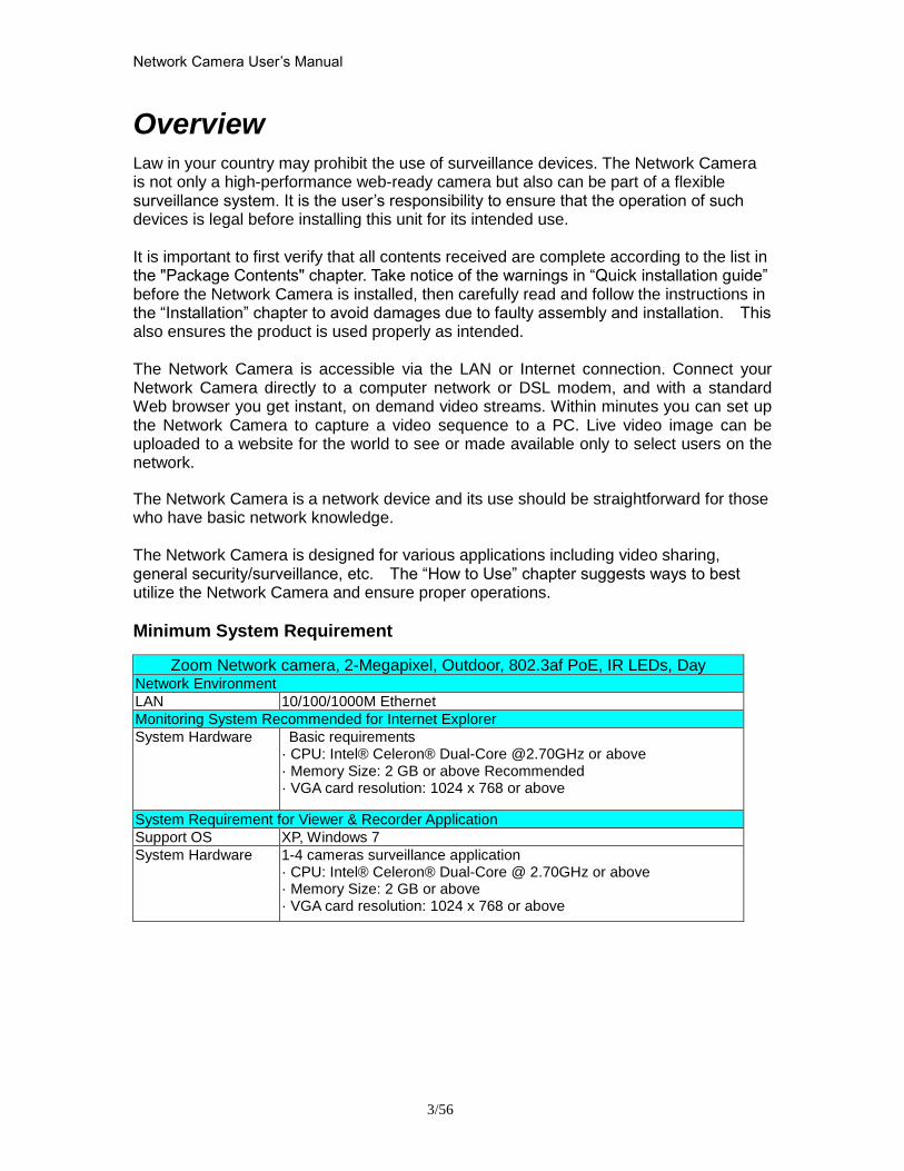
Network Camera Userrsquos Manual
356
Overview
Law in your country may prohibit the use of surveillance devices The Network Camera is not only a high-performance web-ready camera but also can be part of a flexible surveillance system It is the userrsquos responsibility to ensure that the operation of such devices is legal before installing this unit for its intended use It is important to first verify that all contents received are complete according to the list in the Package Contents chapter Take notice of the warnings in ldquoQuick installation guiderdquo before the Network Camera is installed then carefully read and follow the instructions in the ldquoInstallationrdquo chapter to avoid damages due to faulty assembly and installation This also ensures the product is used properly as intended The Network Camera is accessible via the LAN or Internet connection Connect your Network Camera directly to a computer network or DSL modem and with a standard Web browser you get instant on demand video streams Within minutes you can set up the Network Camera to capture a video sequence to a PC Live video image can be uploaded to a website for the world to see or made available only to select users on the network
The Network Camera is a network device and its use should be straightforward for those who have basic network knowledge The Network Camera is designed for various applications including video sharing general securitysurveillance etc The ldquoHow to Userdquo chapter suggests ways to best utilize the Network Camera and ensure proper operations
Minimum System Requirement
Zoom Network camera 2-Megapixel Outdoor 8023af PoE IR LEDs Day Network Environment
LAN 101001000M Ethernet
Monitoring System Recommended for Internet Explorer
System Hardware Basic requirements middot CPU Intelreg Celeronreg Dual-Core 270GHz or above middot Memory Size 2 GB or above Recommended middot VGA card resolution 1024 x 768 or above
System Requirement for Viewer amp Recorder Application
Support OS XP Windows 7
System Hardware 1-4 cameras surveillance application middot CPU Intelreg Celeronreg Dual-Core 270GHz or above middot Memory Size 2 GB or above middot VGA card resolution 1024 x 768 or above
Network Camera Userrsquos Manual
456
Package Contents
If any of the above items are missing please contact your dealer immediately
Note Using a power supply with a different voltage than the one included with the Network Camera will cause damage and void the warranty for this product
Network Camera (Wired or PoE)
Software CD
Power adapter
Quick installation guide
WrenchScrewsWall Mount Bracket
Moisture AbsorberRJ45 Female
Network Camera Userrsquos Manual
556
Connections
Hardware description
Plan view panel
Inner View
Network Camera Userrsquos Manual
656
Hardware Installation 1 Attach the Network Camera with the included stand
2 Place the Camera fix it onto ceiling or wall Use screws to fix the Network Camera onto the ceiling or wall
3 Power over Ethernet (PoE) Using a PoE-enabled switch The Network Camera is PoE-compliant allowing transmission of power and data via a single Ethernet cable Follow the below illustration to connect the Network Camera to a PoE-enabled switch via Ethernet cable
Network Camera Userrsquos Manual
756
General Connection (without PoE) 1 Connect the camera to a switch via Ethernet cable
2 Connect the power cable from the Network Camera to power outlet
4General IO Terminal Block This Network Camera provides a general IO terminal block which is used to connect external input devices The pin definitions are described below
Network Camera Userrsquos Manual
856
Connect to the Network Camera
Install the IP Finder program When you installed your Network camera on your LAN environment you may install ldquoIP Finderrdquo to discover Network camerarsquos IP address The Administrator must place the product software CD into the CD-ROM drive of the PC running in Microsoft Windows An auto-run program will pop up (If the program is not on auto-run go to the root directory of the software CD and click on ldquoautorunexerdquo)
Click on ldquoSoftware Utilityrdquo item after the window contents changed click on ldquoInstall IP Finderrdquo to run ldquoIP Finderrdquo program
Network Camera Userrsquos Manual
956
ldquoIP Finderrdquo is used to search the IP address of Network Cameras or Video servers on a LAN After searching Video Servers or Network Cameras will be located by the IP Finder
Network Camera Userrsquos Manual
1056
Search Camera
Click search Camera button the program will search for all family network devices on the same LAN After searching the main installer window will pop up Click on the MAC and model name which matches the product label on your device to connect to the Network Camera via Internet Explorer
Network Camera Userrsquos Manual
1156
Setup Camera Auto Install Wizard will be started and that it can auto guide through the installation process Press the ldquoNextrdquo button execute next process For more information please refer to the Network section on page 31
Network Camera Userrsquos Manual
1256
Network Camera Userrsquos Manual
1356
Network Camera Userrsquos Manual
1456
Network Camera Userrsquos Manual
1556
Bonjour program Safari browser supports Bonjour search program the will search for all family network devices on the same LAN
Network Camera Userrsquos Manual
1656
C2mylevel1com (Free DDNS service) 1 When you want to connect the network camera over Internet you can use the service ldquoC2mylevel1comrdquo The ldquoip-discoverycomrdquo is a free DDNS server for this camera Make sure that the router must start UPnP and DHCP server functions You can get the domain name which you wish very easily after registration In Network pagemdashDDNS settings of this camera you just input the host name you want and your e-mail address and click ldquoRegisterrdquo then you can have the hostname for this camera not longer than 20 seconds if the DDNS registration result is OK Then you can connect to this ip camera by httpXXXc2mylevel1com XXX the host name you type The HTTP port (get it automatically by c2mylevel1 server)
User password Default the password is last six number of the MAC To change ldquorootrdquo password at ldquoSecurity configurationrdquo can change the user password This ldquoUser passwordrdquo is entered in the c2mylevel1com Password Note You must set the ports between your router and camera manually if the registration is failed
Network Camera Userrsquos Manual
1756
Initial Access to the Network Camera
(1) For the initial access to the Network Camera in Windows the web browser may prompt for permission to install a new plug-in for the Network Camera This plug-in has been registered for certificate and is used to display the video in the browser
Users may click on to proceed
1 Click ldquoInstallrdquo and ldquoRunrdquo ActiveX controls 2 The video will be displayed
Network Camera Userrsquos Manual
1856
Primary userrsquos capability
Main Screen with Camera View The main page has three parts
1 Configuration functions The camera can be configured using these user interfaces
2 Connection control buttons These buttons provide the remote and local switching stream
3 Camera View What the camera sees Click the configuration in the bottom of left column to link to the configuration page
Configuration functions ldquoClient Settingsrdquo Clicking on this button links you to the client setting pages please check the following session for more details
ldquoConfigurationrdquo Please notes that only the administrator can access it ldquo Languagerdquo Click this button to choose a language for the user interface Language options are available in English traditional Chinese Simplified Chinese Japanese Spanish Portuguese French German Italiano
1
2
3
Network Camera Userrsquos Manual
1956
Camera view On the top of image shows the connecting type of the Network Camera and the current datetime
View capabilities
1 Click this button to capture and save still images The captured images will be
displayed in pop-up window Right-click the image and choose Save Picture As to save it in JPEG format
2 The button selection lets you open a digital zoom and to control the window to
enlarge a specified area in the camera view
3 Click this button to switch to full screen mode Press the ldquoEscrdquo key to switch back to normal mode
4 Click on this button freeze the video and playing when you click again
5 Click on this button stop video output
6 Use this functionyou can record video in your PC by browser directly The files
format will be in MP4
7 Click on this button adjust the audio volume amp Latency
8 Click on this button switch Mute OnOff
9 Click on this button to adjust the Function ldquo2-way audiordquo to be EnableDisable Enable this function request insert an external speaker The server can play sound from the client and receive sound from the environment and send to client
10 Click on this button to adjust the Microphone volume
Network Camera Userrsquos Manual
2056
11 Click on this button switch Microphone Mute OnOff Connection control buttons
1 ldquoConnectionrdquo User can choose Remote or Local mode for best connection quality Proposal Internet environment switch Remote mode
2 ldquoVideo Streamrdquo User can choose stream1 or stream2
Network Camera Userrsquos Manual
2156
Client Setting
1 ldquoIntranet Protocol Optionsrdquo Setting camera in intranet mode of protocol ldquoUDPrdquo Select use UDP protocol connect camera ldquoTCPrdquo Select use TCP protocol connect camera ldquoHTTPrdquo Select use HTTP protocol connect camera
2 ldquoInternet Protocol Optionsrdquo Setting camera in internet mode of protocol ldquoUDPrdquo Select use UDP protocol connect camera ldquoTCPrdquo Select use TCP protocol connect camera ldquoHTTPrdquo Select use HTTP protocol connect camera
3 ldquoRecording optionsrdquo Users can record live video as they are watching by
clicking start MP4 Recording on the main page Here you can specify the storage destination and file name
ldquoFolderrdquo Specify the storage destination for the recorded video files ldquoFile name prefixrdquo Enter the text that will be appended to the front of the video
file name ldquoAdd date and time suffix to file namerdquo Select this option to append the date
and time to the end of the file name
Network Camera Userrsquos Manual
2256
NOTEProtocol Options which allows choices on connection protocol between client and
server There are three protocols choices to optimize your usage ndash UDP TCP HTTP The UDP protocol allows for more real-time audio and video streams However some packets may be lost due to network burst traffic and images may be obscured The HTTP protocol allows for less packet loss and produces a more accurate video display The downside with this protocol is that the real-time effect is worse than that with the UDP protocol The TCP guarantees the complete delivery of streaming data and thus provides better video quality However the real-time effect is not as good as that of the UDP protocol If no special need is required UDP protocol is recommended Generally speaking the client choice will be in the order of UDP rarr HTTP After the Network Camera is connected successfully ldquoProtocol Optionrdquo will indicate the selected protocol The selected protocol will be recorded in the users PC and will be used for the next connection If the network environment is changed or the user wants to let the web browser to detect again manually select the UDP and TCP protocol save and return HOME to re-connect
Network Camera Userrsquos Manual
2356
Definitions in Configuration
Please note that only the Administrator can access the system configuration Each category in the left column will be explained on the following pages
System parameters
1 ldquoGeneral Settingrdquo
(1) ldquoHost namerdquo The text displays the title on the top of the main page
Firmware version
Network Camera Userrsquos Manual
2456
2 ldquoTime Settingrdquo (1) ldquoTime zonerdquo Choose a time zone from the down arrow
(2) ldquoDaylight savingrdquo For summertime It will be one hour ahead
(3) ldquoCurrent Timerdquo Network camera set the current time
(A) ldquoKeep current date and timerdquo Click on this to keep the current date and time of the Network Camera An internal real-time clock maintains the date and time even when the power of the system is turned off
(B) ldquoSync with computer timerdquo Synchronize the date and time in the Network Camera according to the local computer
(C) ldquoManualrdquo Adjust the date and time by the Administrator
(D) ldquoAdjust by NTP serverrdquo Synchronize the time according NTP server over the Internet whenever the Network Camera is switched on It fails if the assigned time-server cannot be found
(a) ldquoNTP serverrdquo Assign the IP address or domain name of the time-server Leaving the text box blank connects the Network Camera to the default time-servers
(b) ldquoUpdate intervalrdquo Select 0 ~ 23 hours update with the time on the NTP server
3 ldquoDI statusrdquo Please go to Application page for setting the DI
Network Camera Userrsquos Manual
2556
Security
Security setting The administrator account name is ldquorootrdquo which is permanent and can not be deleted If you want to add more accounts in the Manage User column please set a password for the ldquorootrdquo account first 1 ldquoChange root passwordrdquo Change the Administratorrsquos password by typing in the new password identically in both text boxes The typed entries will be displayed as asterisks for security purposes After pressing ldquofinishrdquo the web browser will ask the Administrator for the new password to access
2 ldquoManage privilegerdquo You can modify the manage privilege of operators or viewers Check or uncheck the item then click finish to enable the settings
3 ldquoManage userrdquo (1) ldquoAdd a new userrdquo Administrators can add up to 20 user accounts
(A) Input the new userrsquos name and password (B) Select the privilege level for the new user account Click Finish to enable the
setting
(2) ldquoDelete a userrdquo Select an existing user name Click Finish to enable the setting
Network Camera Userrsquos Manual
2656
(3) ldquoUpdate a existing userrdquo Select an existing user name Administrators can modify userrsquos password and privilege Click Finish to enable the setting
Access rights are sorted by user privilege (Administrator Operator and Viewer) Only administrators can access the Configuration page Operators cannot access the Configuration page but can use the URL Commands to get and set the value of parameters Viewers access only the main page for live viewing
Network
Any changes made on this page will restart the system in order to validate the changes Make sure every field is entered correctly before clicking on ldquofinishrdquo
Network Camera Userrsquos Manual
2756
Network Setting ldquoLANrdquo amp ldquoPPPoErdquo The default type is LAN Select PPPoE if using ADSL
1 LAN
The default status is Get IP address automatically This could be tedious to perform software installation whenever the Network Camera starts Therefore once the network is set especially for the IP address should be entered correctly Select Use fixed IP address then the Network Camera will skip installation The Network Camera will automatically restart and operate normally after a power outage You can run IP installer to check the IP address assigned to the Network Camera if the IP address is forgotten or you can use the UPnP function provided by the Network Camera (MS Windows XP provides UPnP function at My Network Place)
(1) ldquoGet IP address automaticallyrdquo (2) ldquoUse fixed IP addressrdquo
- ldquoIP addressrdquo This is necessary for network identification - ldquoSubnet maskrdquo This is used to determine if the destination is in the same subnet The default value is ldquo2552552550rdquo - ldquoDefault routerrdquo This is a gateway used to forward frames to destinations in a different subnet Invalid router setting will fail the transmission to destinations in different subnet - ldquoPrimary DNSrdquo The primary domain name server that translates hostnames into IP addresses - ldquoSecondary DNSrdquo Secondary domain name server backups the Primary DNS - ldquoEnable UPnP presentation amp port forwardingrdquo Enable UPnP ability - ldquoHttp portrdquo This can be typed besides the default Port 80 Once the port is changed the users must make sure the change for the connection is successful For instance when the Administrator changes the HTTP port of the Network Camera which IP address is 192168020 from 80 or 1025 to 65535 the users must type in the web browser ldquohttp1921680208080rdquo instead of ldquohttp192168020rdquo
- ldquoRTSP Portrdquo RTSP port can be typed besides the default Port 554 - ldquoRTP Portrdquo The RTP port can be typed besides the default Port 54
Note Please set Video RTP port in even number after default value port 54 Then
Video RTCP potAudio RTP portAudio RTCP port will automatically set the
values in ascending
- ldquoRTSP Streaming access namesrdquo The RTSP streaming currently supports video only audio only and audiovideo To use the audiovideo stream type the URL asldquortsp613012543liveNsdprdquo
2 PPPoE If using the PPPoE interface you should fill the following settings from ISP
(1) ldquoUser namerdquo The login name of PPPoE account (2) ldquoPasswordrdquo The password of PPPoE account (3) ldquoConfirm passwordrdquo Input password again for confirmation
Network Camera Userrsquos Manual
2856
DDNS Setting 1 ldquoEnable DDNSrdquo This option turns on the DDNS function
2 ldquoip-discoveryrdquo In the Register column fill in the Host name (xxxx ip-discovery) Email Key and Confirm Key then click Register After a host name has been successfully created a success message will be displayed in the DDNS Registration Result column and messaging E-mail
3 ldquo3rd party DDNSrdquo This is enable or disable 3rd party DDNS 4 ldquoProviderrdquo The provider list contains hosts that provide DDNS services Please connect to the service providerrsquos website to make sure the service charges
5 ldquoHost Namerdquo If the User wants to use DDNS service this field must be filled Please input the hostname that is registered in the DDNS server
6 ldquoUser namerdquo The Username or E-mail field is necessary for logging in the DDNS server or notify the User of the new IP address Note when this field is input as ldquoUser namerdquo the following field must be input as ldquoPasswordrdquo
7 ldquoPasswordrdquo Please input the password or key to get the DDNS service
8 ldquofinishrdquo Click on this button to save modify settings for the DDNS service
Network Camera Userrsquos Manual
2956
Access list
Access list setting 1 How to control access permission by verifying the client PCrsquos IP
address General Settings General Settings
Add a rule to configure an AllowedDenied list Click Add to add a rule
Network Camera Userrsquos Manual
3056
to AllowedDenied list There are three types of rules for user to set up ldquoSinglerdquo This rule allows the user to add an IP address to the AllowedDenied list For example
ldquoNetworkrdquo This rule allows the user to assign a network address and corresponding subnet mask to the AllowDeny List The IP address is written in the CIDR format For example
Network Camera Userrsquos Manual
3156
ldquoRangerdquo This rule allows the user to assign a range of IP addresses to the AllowDeny List This rule is only applied to IPv4 For example
Network Camera Userrsquos Manual
3256
Audio and Video setting
Network Camera Userrsquos Manual
3356
General Setting 1 ldquoColor moderdquo Select use color or monochrome video display
2 ldquoVideo orientationrdquo The orientation of video
(1) ldquoFliprdquo Vertically rotate the video
(2) ldquoMirrorrdquo Horizontally rotates the video
3 ldquoEnvironmentrdquo The orientation of video
(1) ldquoindoorrdquo This option is usually selected when the Network Camera is placed in indoor environments
(2) ldquooutdoorrdquo This option is usually selected when the Network Camera is placed in outdoor environments
4 ldquoPower freqrdquo Select 50 Hz or 60Hz power line frequency
The fluorescent light will flash according to the power line frequency that
depends on local utility Change the frequency setting to eliminate uncomfortable flash image when the light source is only fluorescent light
Video Setting 1 ldquoContrastrdquo Adjust the image contrast level which ranges from -5 to +5 The default value is set to 0
2 ldquoBrightnessrdquo Adjust the image brightness level which ranges from -5 to +5 The default value is set to 0
3 ldquoSaturationrdquo Adjust the image saturation level which ranges from -5 to +5 The default value is set to 0
4 ldquoSharpnessrdquo Adjust the image sharpness level which ranges from -5 to +5 The default value is set to 0
5 ldquoEVrdquo Exposure value represent the expected target value of the luminance of
the weighting result of AE windows in the image and its tolerance as offset
6 ldquoGainrdquo In the slide bar of Gain there are also two sliders which represent the
limitations to control the maximum gain value and the minimum one respectively Normally the minimum value is to 1x for better quality
Network Camera Userrsquos Manual
3456
Exposure setting Here it provides 3 mode Auto Backlight and Customized Auto and
Backlight modes are 2 default settings for general purpose and backlight scene
respectively
Customized mode relates to the grid window above can be pointed on for
interesting areas Within the mode Customized 1615 grids windows can be chosen to match wherewhat you are interested in Push down left-button of mouse and drag to draw the grids for interesting areas or push down right-button of mouse and drag to clean the grids for insignificant areas
ldquoTarget Luminance and Offsetrdquo
These two slide bar Target Luminance and Offset represent the expected
target value of the luminance of the weighting result of AE windows in the image and its tolerance as offset For example target luminance is set to 100 and target offset is set to 20 that means the average luminance of the AE window should be in the range from 80 to 120 (100plusmn(10 When the actual luminance does not meet this range the AE function will adjust shutter and gain to meet it as possible In some extreme cases it cannot reach the target because the environment is too bright or dark When the environment is not consistent eg with big moving objects and the offset is too narrow the AE will act more frequently that will cause the background of view inconsistent The offset value is recommended to set 15~25 of target luminance
Network Camera Userrsquos Manual
3556
ldquoGainrdquo
In the slide bar of Gain there are also two sliders which represent the limitations
to control the maximum gain value and the minimum one respectively Normally the minimum value is to 1x for better quality It is not allowed if the maximum slider and the minimum one are set to the same value without adjustable interval Besides the noise will be increased if the actual gain is too large When the max slider is dragged over sensors max gain the slide bar will become deep blue to represent it will apply Mozart 3s digital gain which extend the max gain for very low light
ldquoShutter Speedrdquo
There are 2 fields minimal and maximal time for the range of Shutter Speed
The precision of the parameter is 11000000 sec but it is NOT actual precision of the shutter speed of the sensor The actual precision of the shutter speed depends on each sensorrsquos specification Here it will be rounded to approach sensorrsquos effective exposure time To avoid flickering or banding phenomenon under fluorescent light the actual shutter speed will be locked at 1120 160
130 if Power Line Frequency is 60Hz or 1100 150 125 if Power Line
Frequency is 50Hz The setting of Power Line Frequency is on the sub-tab Video
and Audio The exposure may not be stable if the maximum value and the minimum one are set to the same value without adjustable interval Besides the frame rate will drop down if the actual shutter speed is too slow to meet expected frame rate
Noise reduction
Provides 2D and 3D features
Wide Dynamic Range Enable Wide Dynamic Range auto in different level to improve the exposure when both bright and dark areas simultaneously in the field of view of the camera The default is off
Infrared Led Setting 1 ldquoInfrared LED Controlrdquo IR led for Day and Night (Option) User can turn onoff the built-in IR led This function is very useful under low illumination environment
(1) ldquoAutordquo Select IR sensitivity from 0 to 4
(2) ldquoManualrdquo Turn onoff the IR led manually
- ldquoTurn onrdquo Turn on led - ldquoTurn offrdquo Turn off led
2 ldquoLow lux moderdquo The video quality will be improved when the camera is in low lux environment (1) ldquoDisable dark moderdquo Disable low lux mode
(2) ldquoEnable dark moderdquo Enable low lux mode
Network Camera Userrsquos Manual
3656
Video output Setting 1 ldquovideo outputrdquo Can switch between NTSC and PAL
Audio Setting 1 ldquoMuterdquo Audio mute
2 ldquoMicrophone rdquo External microphone
3 ldquoMic Volumerdquo Adjust microphone volume which ranges from 1 to 46
Video record
Schedule mode
(1) ldquoEvery dayrdquo EnableDisable every day application
(2) ldquoWeek dayrdquo EnableDisable week day application
(3)ldquoSelected dayrdquo EnableDisable selected day application
Schedule information
(1) Enter the ldquoStart timerdquo and ldquoStop timerdquo for day mode Note that the time format is [hhmm] and is expressed in 24-hour clock time By default the start and end time of day mode are set to 010000 and 235959
Network Camera Userrsquos Manual
3756
(2)ldquoSunrdquoldquoMonrdquoldquoTuerdquoldquoWedrdquoldquoThurdquoldquoFrirdquoldquoSatrdquo Select the days of the week to perform the application
(3) ldquoStart dayrdquo and ldquoStart timerdquo as the start timing the time ldquoEnd dayrdquo and ldquoEnd timerdquo as the end timing the time
(4) ldquoEnable cyclic recordingrdquo The cyclic recording function is enabled during the transaction stage when a storage space is full and the incoming streaming data is about to overwrite the previously saved videos
Record parameters (1)Source Select a stream for the recording source
(2)Recording interval Select the recording time interval
(3)Prefix file name You can setting the file name and enable or disable to add the date and time on file name
Response mode There are two choices of server types available NAS SD Card Select the item to display the detailed configuration options
(1)rdquoNASrdquo
--ldquoNAS server addressrdquo Enter IP address of the NAS server
--ldquoNAS shared directoryrdquo Enter the NAS shared directory path --ldquoWorkgrouprdquo Enter the NAS workgroup parameter --ldquoUser accountrdquo Enter the login name of the NAS account --ldquoUser passwordrdquo Enter the password of the NAS account Note Video record with the Application must be set to the same shared directory
path If you would like do detail recording settings or multi-channel recording please install bundled 64CH recording software in CD
Network Camera Userrsquos Manual
3856
Stream
Audio codec setting
(1)ldquoAudio codec typerdquo There are two choices of audio codec types
available rdquoAMRrdquo ldquoAACrdquo and rdquoG711rdquo
(2) ldquoBit raterdquo -- ldquoAMRrdquo The bit rates are selectable at the following rates
47505150590067007400795010200 and 12200
-- ldquoAACrdquo The bit rates are selectable at the following rates 8Kbps16Kbps 24Kbps and 32Kbps
-- ldquoG711rdquo pcmu and pcma
Video codec setting (1) ldquoSelect Streamrdquo The Network Camera supports ldquoStream 1rdquoand ldquoStream 2rdquo
(2) ldquoVideo codecrdquo The Network Camera supports three kind of video compression mode ldquoH264rdquo or ldquoMPEG4rdquo or ldquoMJPEGrdquo User can choose one of
Network Camera Userrsquos Manual
3956
these compression modes based on requirement or application
(3) ldquoVideo sizerdquo Click the down arrow to choose the quality of image (1920x1080 1280x1024 1280x800 640x480 320x240 176x144)
(4) ldquoConnection typerdquo User can select this button to choose the better video amp links quality (Internet mode or Intranet mode)
(5) ldquoFrame raterdquo This limits the maximal refresh frame rate per second Set the frame rate higher for a smoother video quality
(6) ldquoIntra frame periodrdquo Determine how often to plant an ldquoI framerdquo The shorter the duration the more likely you will get a better video quality but at the cost of higher network bandwidth consumption
(7) ldquoVideo Quality typerdquo Setting optimizes bandwidth utilization and video quality
-- ldquoConstant bit raterdquo User can adjust the video quality from 20 Kbps to 12 Mbps
-- ldquoFixed qualityrdquo user can select from lowest quality to get best quality according The ldquoQualityrdquo are selectable at the following rates From 1 to 20
Snapshot and time display setting Adjust the photo size specifications and choose whether to mark time on the video and photo
Network Camera Userrsquos Manual
4056
Application
Schedule mode
(1) ldquoEvery dayrdquo EnableDisable every day application
(2) ldquoWeek dayrdquo EnableDisable week day application
(3) ldquoSelected dayrdquo EnableDisable selected day application
Schedule information (1) Enter the ldquoStart timerdquo and ldquoStop timerdquo for day mode
Note that the time format is [hhmmss] and is expressed in 24-hour clock time By default the start and end time of day mode are set to 010000 and 235959
(2) ldquoSunrdquoldquoMonrdquoldquoTuerdquoldquoWedrdquoldquoThurdquoldquoFrirdquoldquoSatrdquo Select the days of the week to perform the application
(3) ldquoStart dayrdquo and ldquoStart timerdquo as the start timing the time ldquoEnd dayrdquo and ldquoEnd timerdquo as the end timing the time
Trigger mode
(1) ldquoVideo motion detectionrdquo EnableDisable video motion application (2) ldquoPeriodicallyrdquo This option allows the Network Camera to trigger
periodically for every other defined minute
Network Camera Userrsquos Manual
4156
(3) ldquoDigital inputrdquo This option allows the Network Camera to use an external digital input device or sensor as a trigger source Depending on your application there are many choices of digital input devices on the market which helps to detect changes in temperature vibration sound and light etc
parameters
(1) ldquoMotion parametersrdquo Higher sensitivity and small threshold will allow easier motion detection
(2) ldquoPeriod parametersrdquo This option allows the Network Camera to trigger periodically for every other defined seconds Up to 999 seconds are allowed
(3) ldquoDigital input parametersrdquo Select the digital input type and set trigger time
Media mode There are four choices of media types available ldquoSnapshotrdquo ldquoMessagerdquo ldquoRecord(Motion Detection only)rdquo and ldquoSystem logrdquo
Snapshot amp Record file setting You can setting the file name and enable or disable to add the date and time on file name Can setting the digital output duration seconds Response mode There are four choices of server types available Email FTP NAS and SD Card storage Select the item to display the detailed configuration options
(1)ldquoEmailrdquo -- ldquoEmail security moderdquo If your SMTP server requires a secure connection (SSL or TLS) check This server requires a secure connection (SSL or TLS) -- ldquoSender emailrdquo address Enter the email address of the sender -- ldquoRecipient emailrdquo address Enter the email address of the recipient
-- ldquoServer addressrdquo Enter the domain name or IP address of the email server
--ldquoUser namerdquo Enter the user name of the email account if necessary
--ldquoPasswordrdquo Enter the password of the email account if necessary
--ldquoServer portrdquo The default mail server port is set to 25 You can also manually set another port
(2)rdquoFTPrdquo -- ldquoServer addressrdquo Enter the domain name or IP address of the FTP server
-- ldquoServer portrdquo By default the FTP server port is set to 21
-- ldquoUser namerdquo Enter the login name of the FTP account
-- ldquoPasswordrdquo Enter the password of the FTP account
-- ldquoFTP folder namerdquo Enter the folder where the media file will be placed If the folder name does not exist the Network Camera will create one on the FTP server
(3)rdquoHTTP rdquo
-- ldquoURLrdquo Enter the URL of the HTTP server
-- ldquoUser accountrdquo Enter the user name if necessary -- ldquoUser passwordrdquo Enter the password if necessary
(4)rdquoNASrdquo --ldquoNAS server addressrdquo Enter IP address of the NAS server
--ldquoNAS shared directoryrdquo Enter the NAS shared directory path
Network Camera Userrsquos Manual
4256
--ldquoWorkgrouprdquo Enter the NAS workgroup parameter --ldquoUser accountrdquo Enter the login name of the NAS account --ldquoUser passwordrdquo Enter the password of the NAS account Note Video record with the Application must be set to the same shared directory
path If you would like do detail recording settings or multi-channel recording please install bundled 64CH recording software in CD
Network Camera Userrsquos Manual
4356
Storage
Manage the storage device
S torage Status Here show the storage device information
NAS server setting
1
2
3
Network Camera Userrsquos Manual
4456
(1) ldquoNAS Host namerdquo Choose and input the NAS Host name of this camera
(2) ldquoWorkgrouprdquo Input the name of Workgroup You can see the NAS Host name you input in the same workgroup with your PC Then you can connect to this device and download the files easily from SD card which is inserted to this camera
File operation Move the mouse over the file Press the mouse right button that Right-click menu is displayed You can delete files Move the mouse over the directory Press the mouse left button that the file structure expand Press the mouse right button that Right-click menu is displayed You can choose upload or delete files NOTEAllow the user to upload or delete files when the storage device is not write-
protected If the SD card canrsquot be detected please link to the following URL httpwwwsdcardorgconsumersformatter to download the ldquoSD Formatter Kitrdquo formatting your SD card
Network Camera Userrsquos Manual
4556
Syslog
The Network camera supports log the system messages on remote server The protocol is compliant to RFC 3164 If you have external Linux server with sys log service use ldquo-rrdquo option to turn on the facility for receiving log from remote machine Or you can use some software on Windows that is compliant to RFC 3164 An example is Kiwi Syslog Daemon Visit httpwwwkiwisyslogcomkiwi-syslog-daemon-overview Check ldquoSetuprdquo and ldquoEnablerdquo then input the ldquoIP addressrdquo and ldquoportrdquo number of the log server to enable the remote log facility In the ldquoCurrent logrdquo it displays the current system log file The content of the log provides useful information about configuration and connection after system boot- up
ldquofinishrdquo Click on this button to save modify settings
Network Camera Userrsquos Manual
4656
Status and Parameters
User can find a lot of information about the system such as ldquoUpnp port forwardingrdquo
ldquoTraversing NATrdquo ldquoPublic IPrdquo and so on User also can get the number of current viewer of the Network Camera here
Network Camera Userrsquos Manual
4756
Maintenance
1 ldquoReboot systemrdquo The ldquoRebootrdquo button will reboot the Network Camera Itrsquos useful while the Network Camera got problem 2 ldquoRestore systemrdquo Click on ldquoRestorerdquo button on the configuration page to restore the factory default settings Restore all settings to factory default except settings in ldquoNetwork type rdquo and ldquoRoot Passwordrdquo The system will restart and require the installer program to set up the network again
3 ldquoCalibraterdquo Recalibrate the auto focus position to the default range to recover the tolerance caused by some external forces 4 ldquoExportImport filerdquo -- Export setting backup file Click to export all parameters for the device and user-defined scripts
-- Upload setting backup file Click Browsehellip to upload a setting backup file Please note that the model and firmware version of the device should be the same as the setting backup file If you have set up a fixed IP or other special settings for your device it is not suggested to upload a settings backup file
4 ldquoUpgrade firmwarerdquo Select the firmware file and click upgrade button Please be aware that you should not turn off the power during updating the firmware and wait for finish message
Network Camera Userrsquos Manual
4856
Warning The upgrade firmware procedure cannot be interrupted If the power
andor network connection are broken during the procedure it might possibly cause serious damage to the Network Camera
Note When upgrade firmware please wait for 120~210 seconds and then you can connect to Network Camera again The system will restart and require the installer program to set up the network again
Network Camera Userrsquos Manual
4956
Appendix
A Troubleshooting amp Frequently Asked Questions Q1 Status led does not light up
A1 First make sure that「ConfigurationgtSystemgtTurn off the LED indicator」is disabled
If it is check the item and the led should light up Second if red led does not light up please check that the power adapter in the package is plugged correctly And last if green led does not light up please check that category 5 UTP cable is plugged correctly If the problem is still not solved please contact your dealer for further help
Q2 What kind of Ethernet cable is used by network camera
A2 The network Camera uses Category 5 UTP cable allowing 10 andor 100 Base-T networking
Q3 The Network Camera will be installed and work if a firewall exists on
the network
A3 There are two way to set up the IP camera at Internet (1) By UPnP Port Forwarding 1 Select an IP router It must support UPnP port forwarding and enable this function
first
2 Connect camera RJ45 cable to IP router and the router is also connected to Internet
3 Plug power cord to camera
4 Go to camera Network page Enable UPnP port forwarding
5 Check camera status we can see the ports had been successfully opened
Network Camera Userrsquos Manual
5056
6Type IP address8080 at browser Then you can see camera through Internet
7You can also type the ddns name at below label of camera on browser URL field For example you may type ah00001ip-discoverycom8080 (2) By Setting Port Forwarding Manually 1 Select a router Set the port forwarding as following
Network Camera Userrsquos Manual
5156
PS Port 80 is HTTP Port port 53 is stream port port 554 is RTSP port and port 443 is HTTPS port 2Go to camera Network page Disable UPnP port forwarding function
Network Camera Userrsquos Manual
5256
3 Type IP address at browser Then you can see camera through Internet
4 You can also type the ddns name at below label of camera on browser URL field For example you may type ah00001ip-discoverycom
Note The firewall software at PC may block the transfer of network camera Please remove or stop the kind software
Q4 How can I find the network camera in the local area network
A4 By using the IP Finder2 program or using UPnP to find it
Q5 IP Finder2 program cannot find Network Camera in the local area
network at first time
A5 Make sure the subnet of network camera is same as your PC If the local area network supports DHCP the camera is ldquoGet IP address automaticallyrdquo in the ldquoNetworkrdquo page default If the local area network does not support DHCP change your PC IP address to ldquo1921680xxxrdquo
Network Camera Userrsquos Manual
5356
Q6 How can I restore the network camera to default value
A6 Use a gem clip to press on the inside button Network camera begins to restore default value You can also press the button ldquoFactoryrdquo in ldquoMaintenancerdquo page to restore the default value
Q7 I cannot play the recorded video file
A7 Install the audio codec in the CD and use the Windows Media Player 10 or later to play the ASF or AVI file recorded by the network camera
Q8 Infrared led does not light up
A8 Check「ConfigurationgtAudio and VideogtInfrared LED Control」 is ldquoAutordquo or
ldquoManual》Turn onrdquo
Q9 The network camera cannot focus accurately
A9 (1) The lens is dirty or dust is attached Clean the lens with lens cleaner And then adjust the camera focus manually (2) The image may be out of focus If the object is too near move the object away from Network Camera
Q10 The cover of network camera is warm Is it normal
A10 Network camera is a precision device The internal material has the operational temperature and it is normal when user touch the cover feels warm It is recommended to put the network camera at aired place and not put at any other device
Q11 The process of upgrade firmware abort
A11 Contact your dealer for further help
Q12 Cannot access the login page and other web pages of Network
Network Camera Userrsquos Manual
5456
Camera from Internet Explorer
A12 bull May be due to the network cable Try correcting your network cable and configuration Test the network interface by connecting a local computer to the Network Camera via a crossover cable bull Make sure the Internet connection and setting is ok bull Make sure enter the IP address of Internet Explorer is correct If Network Camera has a dynamic address it may have changed since you last checked it bull Network congestion may prevent the web page appearing quickly Wait for a while The IP address and Subnet Mask of the PC and Network Camera must be in the same class of the private IP address on the LAN bull Make sure the http port used by the Network Camera default=80 is forward to the Network Camerarsquos private IP address bull The port number assigned in your Network Camera might not be available via Internet Check your ISP for available port bull The proxy server may prevent you from connecting directly to Network Camera set up not to use the proxy server bull Confirm that Default Gateway address is correct bull The router needs Port Forwarding feature Refer to your routers manual for details bull Packet Filtering of the router may prohibit access from an external network Refer to your routers manual for details bull Access Network Camera from the Internet with the global IP address of the router and port number of Network Camera bull Some routers reject the global IP address to access Network Camera on the same LAN Access with the private IP address and correct port number of Network Camera bull When you use DDNS you need to set Default Gateway and DNS server address bull If itrsquos not working after above procedure reset Network Camera to default setting and installed it again bull Maybe the IP Address of the Network Camera is already being used by another device or computer bull If the problem is not solved the Network Camera might be faulty Contact your dealer for further help
Network Camera Userrsquos Manual
5556
B Technical specifications
- System RAM 4G bit DDRⅢ
ROM 16MB Flash ROM
- Camera specification 127 inch color CMOS sensor Resolution 1920x1080 10LuxF20 AGC AWB AEC
- Infrared Led High power IR Leds 25~30 M visible AutoManual mode
- Lens 3X optical zoom lens auto iris auto focus f = 28~ 12mm F18 Fov(D) 136deg ~ 39deg
- Protocol TCPIP HTTPUDP SMTP FTP DDNS UPnP Telnet NTP PPPoE RTSP RTPRTCPDHCP and DNS
- Video Resolution Up to 30 frames at 176x144 Up to 30 frames at 320x240 Up to 30 frames at 640x480 Up to 30 frames at 1280x800 Up to 30 frames at 1280x1024 Up to 30 frames at 1920x1080
- Algorithm supported H264MPEG4MJPEG dual codec for streaming video JPEG for still image
- Audio AMRAACG711 External MIC input 2-way audio
- Physical 10 baseT100 baseT and 1000 baseT Fast
Ethernet auto negotiation
- Power Input 100-240VAC 5060Hz 07A Output 12VDC 15A Consumption Max 12 W Support 8023af compliant Power over Ethernet
- EMI amp Safety CE FCC
- Dimension Length 165mm Diameter 75mm
- Operating Environment Temperature -20 ~ 50
Humidity 85 RH
- Weight NET 600g With bracket 800g
Network Camera Userrsquos Manual
5656
Notification of Compliance Appendix C
Europe - EU Declaration of Conformity
For complete DoC please visit httpgloballevel1comdownloadsphpaction=init
GPL License Agreement GPL may be included in this product to view the GPL license agreement goes to httpdownloadlevel1comlevel1gplGPLpdf For GNU General Public License (GPL) related information please visit httpgloballevel1comdownloadsphpaction=init
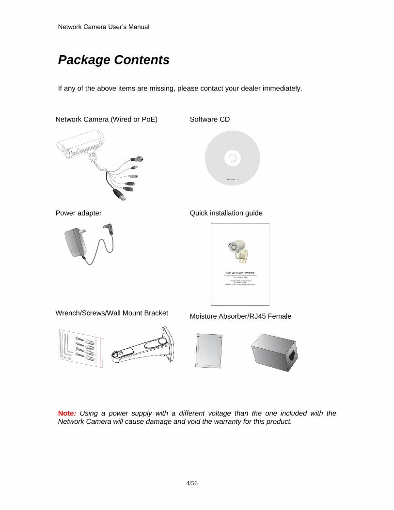
Network Camera Userrsquos Manual
456
Package Contents
If any of the above items are missing please contact your dealer immediately
Note Using a power supply with a different voltage than the one included with the Network Camera will cause damage and void the warranty for this product
Network Camera (Wired or PoE)
Software CD
Power adapter
Quick installation guide
WrenchScrewsWall Mount Bracket
Moisture AbsorberRJ45 Female
Network Camera Userrsquos Manual
556
Connections
Hardware description
Plan view panel
Inner View
Network Camera Userrsquos Manual
656
Hardware Installation 1 Attach the Network Camera with the included stand
2 Place the Camera fix it onto ceiling or wall Use screws to fix the Network Camera onto the ceiling or wall
3 Power over Ethernet (PoE) Using a PoE-enabled switch The Network Camera is PoE-compliant allowing transmission of power and data via a single Ethernet cable Follow the below illustration to connect the Network Camera to a PoE-enabled switch via Ethernet cable
Network Camera Userrsquos Manual
756
General Connection (without PoE) 1 Connect the camera to a switch via Ethernet cable
2 Connect the power cable from the Network Camera to power outlet
4General IO Terminal Block This Network Camera provides a general IO terminal block which is used to connect external input devices The pin definitions are described below
Network Camera Userrsquos Manual
856
Connect to the Network Camera
Install the IP Finder program When you installed your Network camera on your LAN environment you may install ldquoIP Finderrdquo to discover Network camerarsquos IP address The Administrator must place the product software CD into the CD-ROM drive of the PC running in Microsoft Windows An auto-run program will pop up (If the program is not on auto-run go to the root directory of the software CD and click on ldquoautorunexerdquo)
Click on ldquoSoftware Utilityrdquo item after the window contents changed click on ldquoInstall IP Finderrdquo to run ldquoIP Finderrdquo program
Network Camera Userrsquos Manual
956
ldquoIP Finderrdquo is used to search the IP address of Network Cameras or Video servers on a LAN After searching Video Servers or Network Cameras will be located by the IP Finder
Network Camera Userrsquos Manual
1056
Search Camera
Click search Camera button the program will search for all family network devices on the same LAN After searching the main installer window will pop up Click on the MAC and model name which matches the product label on your device to connect to the Network Camera via Internet Explorer
Network Camera Userrsquos Manual
1156
Setup Camera Auto Install Wizard will be started and that it can auto guide through the installation process Press the ldquoNextrdquo button execute next process For more information please refer to the Network section on page 31
Network Camera Userrsquos Manual
1256
Network Camera Userrsquos Manual
1356
Network Camera Userrsquos Manual
1456
Network Camera Userrsquos Manual
1556
Bonjour program Safari browser supports Bonjour search program the will search for all family network devices on the same LAN
Network Camera Userrsquos Manual
1656
C2mylevel1com (Free DDNS service) 1 When you want to connect the network camera over Internet you can use the service ldquoC2mylevel1comrdquo The ldquoip-discoverycomrdquo is a free DDNS server for this camera Make sure that the router must start UPnP and DHCP server functions You can get the domain name which you wish very easily after registration In Network pagemdashDDNS settings of this camera you just input the host name you want and your e-mail address and click ldquoRegisterrdquo then you can have the hostname for this camera not longer than 20 seconds if the DDNS registration result is OK Then you can connect to this ip camera by httpXXXc2mylevel1com XXX the host name you type The HTTP port (get it automatically by c2mylevel1 server)
User password Default the password is last six number of the MAC To change ldquorootrdquo password at ldquoSecurity configurationrdquo can change the user password This ldquoUser passwordrdquo is entered in the c2mylevel1com Password Note You must set the ports between your router and camera manually if the registration is failed
Network Camera Userrsquos Manual
1756
Initial Access to the Network Camera
(1) For the initial access to the Network Camera in Windows the web browser may prompt for permission to install a new plug-in for the Network Camera This plug-in has been registered for certificate and is used to display the video in the browser
Users may click on to proceed
1 Click ldquoInstallrdquo and ldquoRunrdquo ActiveX controls 2 The video will be displayed
Network Camera Userrsquos Manual
1856
Primary userrsquos capability
Main Screen with Camera View The main page has three parts
1 Configuration functions The camera can be configured using these user interfaces
2 Connection control buttons These buttons provide the remote and local switching stream
3 Camera View What the camera sees Click the configuration in the bottom of left column to link to the configuration page
Configuration functions ldquoClient Settingsrdquo Clicking on this button links you to the client setting pages please check the following session for more details
ldquoConfigurationrdquo Please notes that only the administrator can access it ldquo Languagerdquo Click this button to choose a language for the user interface Language options are available in English traditional Chinese Simplified Chinese Japanese Spanish Portuguese French German Italiano
1
2
3
Network Camera Userrsquos Manual
1956
Camera view On the top of image shows the connecting type of the Network Camera and the current datetime
View capabilities
1 Click this button to capture and save still images The captured images will be
displayed in pop-up window Right-click the image and choose Save Picture As to save it in JPEG format
2 The button selection lets you open a digital zoom and to control the window to
enlarge a specified area in the camera view
3 Click this button to switch to full screen mode Press the ldquoEscrdquo key to switch back to normal mode
4 Click on this button freeze the video and playing when you click again
5 Click on this button stop video output
6 Use this functionyou can record video in your PC by browser directly The files
format will be in MP4
7 Click on this button adjust the audio volume amp Latency
8 Click on this button switch Mute OnOff
9 Click on this button to adjust the Function ldquo2-way audiordquo to be EnableDisable Enable this function request insert an external speaker The server can play sound from the client and receive sound from the environment and send to client
10 Click on this button to adjust the Microphone volume
Network Camera Userrsquos Manual
2056
11 Click on this button switch Microphone Mute OnOff Connection control buttons
1 ldquoConnectionrdquo User can choose Remote or Local mode for best connection quality Proposal Internet environment switch Remote mode
2 ldquoVideo Streamrdquo User can choose stream1 or stream2
Network Camera Userrsquos Manual
2156
Client Setting
1 ldquoIntranet Protocol Optionsrdquo Setting camera in intranet mode of protocol ldquoUDPrdquo Select use UDP protocol connect camera ldquoTCPrdquo Select use TCP protocol connect camera ldquoHTTPrdquo Select use HTTP protocol connect camera
2 ldquoInternet Protocol Optionsrdquo Setting camera in internet mode of protocol ldquoUDPrdquo Select use UDP protocol connect camera ldquoTCPrdquo Select use TCP protocol connect camera ldquoHTTPrdquo Select use HTTP protocol connect camera
3 ldquoRecording optionsrdquo Users can record live video as they are watching by
clicking start MP4 Recording on the main page Here you can specify the storage destination and file name
ldquoFolderrdquo Specify the storage destination for the recorded video files ldquoFile name prefixrdquo Enter the text that will be appended to the front of the video
file name ldquoAdd date and time suffix to file namerdquo Select this option to append the date
and time to the end of the file name
Network Camera Userrsquos Manual
2256
NOTEProtocol Options which allows choices on connection protocol between client and
server There are three protocols choices to optimize your usage ndash UDP TCP HTTP The UDP protocol allows for more real-time audio and video streams However some packets may be lost due to network burst traffic and images may be obscured The HTTP protocol allows for less packet loss and produces a more accurate video display The downside with this protocol is that the real-time effect is worse than that with the UDP protocol The TCP guarantees the complete delivery of streaming data and thus provides better video quality However the real-time effect is not as good as that of the UDP protocol If no special need is required UDP protocol is recommended Generally speaking the client choice will be in the order of UDP rarr HTTP After the Network Camera is connected successfully ldquoProtocol Optionrdquo will indicate the selected protocol The selected protocol will be recorded in the users PC and will be used for the next connection If the network environment is changed or the user wants to let the web browser to detect again manually select the UDP and TCP protocol save and return HOME to re-connect
Network Camera Userrsquos Manual
2356
Definitions in Configuration
Please note that only the Administrator can access the system configuration Each category in the left column will be explained on the following pages
System parameters
1 ldquoGeneral Settingrdquo
(1) ldquoHost namerdquo The text displays the title on the top of the main page
Firmware version
Network Camera Userrsquos Manual
2456
2 ldquoTime Settingrdquo (1) ldquoTime zonerdquo Choose a time zone from the down arrow
(2) ldquoDaylight savingrdquo For summertime It will be one hour ahead
(3) ldquoCurrent Timerdquo Network camera set the current time
(A) ldquoKeep current date and timerdquo Click on this to keep the current date and time of the Network Camera An internal real-time clock maintains the date and time even when the power of the system is turned off
(B) ldquoSync with computer timerdquo Synchronize the date and time in the Network Camera according to the local computer
(C) ldquoManualrdquo Adjust the date and time by the Administrator
(D) ldquoAdjust by NTP serverrdquo Synchronize the time according NTP server over the Internet whenever the Network Camera is switched on It fails if the assigned time-server cannot be found
(a) ldquoNTP serverrdquo Assign the IP address or domain name of the time-server Leaving the text box blank connects the Network Camera to the default time-servers
(b) ldquoUpdate intervalrdquo Select 0 ~ 23 hours update with the time on the NTP server
3 ldquoDI statusrdquo Please go to Application page for setting the DI
Network Camera Userrsquos Manual
2556
Security
Security setting The administrator account name is ldquorootrdquo which is permanent and can not be deleted If you want to add more accounts in the Manage User column please set a password for the ldquorootrdquo account first 1 ldquoChange root passwordrdquo Change the Administratorrsquos password by typing in the new password identically in both text boxes The typed entries will be displayed as asterisks for security purposes After pressing ldquofinishrdquo the web browser will ask the Administrator for the new password to access
2 ldquoManage privilegerdquo You can modify the manage privilege of operators or viewers Check or uncheck the item then click finish to enable the settings
3 ldquoManage userrdquo (1) ldquoAdd a new userrdquo Administrators can add up to 20 user accounts
(A) Input the new userrsquos name and password (B) Select the privilege level for the new user account Click Finish to enable the
setting
(2) ldquoDelete a userrdquo Select an existing user name Click Finish to enable the setting
Network Camera Userrsquos Manual
2656
(3) ldquoUpdate a existing userrdquo Select an existing user name Administrators can modify userrsquos password and privilege Click Finish to enable the setting
Access rights are sorted by user privilege (Administrator Operator and Viewer) Only administrators can access the Configuration page Operators cannot access the Configuration page but can use the URL Commands to get and set the value of parameters Viewers access only the main page for live viewing
Network
Any changes made on this page will restart the system in order to validate the changes Make sure every field is entered correctly before clicking on ldquofinishrdquo
Network Camera Userrsquos Manual
2756
Network Setting ldquoLANrdquo amp ldquoPPPoErdquo The default type is LAN Select PPPoE if using ADSL
1 LAN
The default status is Get IP address automatically This could be tedious to perform software installation whenever the Network Camera starts Therefore once the network is set especially for the IP address should be entered correctly Select Use fixed IP address then the Network Camera will skip installation The Network Camera will automatically restart and operate normally after a power outage You can run IP installer to check the IP address assigned to the Network Camera if the IP address is forgotten or you can use the UPnP function provided by the Network Camera (MS Windows XP provides UPnP function at My Network Place)
(1) ldquoGet IP address automaticallyrdquo (2) ldquoUse fixed IP addressrdquo
- ldquoIP addressrdquo This is necessary for network identification - ldquoSubnet maskrdquo This is used to determine if the destination is in the same subnet The default value is ldquo2552552550rdquo - ldquoDefault routerrdquo This is a gateway used to forward frames to destinations in a different subnet Invalid router setting will fail the transmission to destinations in different subnet - ldquoPrimary DNSrdquo The primary domain name server that translates hostnames into IP addresses - ldquoSecondary DNSrdquo Secondary domain name server backups the Primary DNS - ldquoEnable UPnP presentation amp port forwardingrdquo Enable UPnP ability - ldquoHttp portrdquo This can be typed besides the default Port 80 Once the port is changed the users must make sure the change for the connection is successful For instance when the Administrator changes the HTTP port of the Network Camera which IP address is 192168020 from 80 or 1025 to 65535 the users must type in the web browser ldquohttp1921680208080rdquo instead of ldquohttp192168020rdquo
- ldquoRTSP Portrdquo RTSP port can be typed besides the default Port 554 - ldquoRTP Portrdquo The RTP port can be typed besides the default Port 54
Note Please set Video RTP port in even number after default value port 54 Then
Video RTCP potAudio RTP portAudio RTCP port will automatically set the
values in ascending
- ldquoRTSP Streaming access namesrdquo The RTSP streaming currently supports video only audio only and audiovideo To use the audiovideo stream type the URL asldquortsp613012543liveNsdprdquo
2 PPPoE If using the PPPoE interface you should fill the following settings from ISP
(1) ldquoUser namerdquo The login name of PPPoE account (2) ldquoPasswordrdquo The password of PPPoE account (3) ldquoConfirm passwordrdquo Input password again for confirmation
Network Camera Userrsquos Manual
2856
DDNS Setting 1 ldquoEnable DDNSrdquo This option turns on the DDNS function
2 ldquoip-discoveryrdquo In the Register column fill in the Host name (xxxx ip-discovery) Email Key and Confirm Key then click Register After a host name has been successfully created a success message will be displayed in the DDNS Registration Result column and messaging E-mail
3 ldquo3rd party DDNSrdquo This is enable or disable 3rd party DDNS 4 ldquoProviderrdquo The provider list contains hosts that provide DDNS services Please connect to the service providerrsquos website to make sure the service charges
5 ldquoHost Namerdquo If the User wants to use DDNS service this field must be filled Please input the hostname that is registered in the DDNS server
6 ldquoUser namerdquo The Username or E-mail field is necessary for logging in the DDNS server or notify the User of the new IP address Note when this field is input as ldquoUser namerdquo the following field must be input as ldquoPasswordrdquo
7 ldquoPasswordrdquo Please input the password or key to get the DDNS service
8 ldquofinishrdquo Click on this button to save modify settings for the DDNS service
Network Camera Userrsquos Manual
2956
Access list
Access list setting 1 How to control access permission by verifying the client PCrsquos IP
address General Settings General Settings
Add a rule to configure an AllowedDenied list Click Add to add a rule
Network Camera Userrsquos Manual
3056
to AllowedDenied list There are three types of rules for user to set up ldquoSinglerdquo This rule allows the user to add an IP address to the AllowedDenied list For example
ldquoNetworkrdquo This rule allows the user to assign a network address and corresponding subnet mask to the AllowDeny List The IP address is written in the CIDR format For example
Network Camera Userrsquos Manual
3156
ldquoRangerdquo This rule allows the user to assign a range of IP addresses to the AllowDeny List This rule is only applied to IPv4 For example
Network Camera Userrsquos Manual
3256
Audio and Video setting
Network Camera Userrsquos Manual
3356
General Setting 1 ldquoColor moderdquo Select use color or monochrome video display
2 ldquoVideo orientationrdquo The orientation of video
(1) ldquoFliprdquo Vertically rotate the video
(2) ldquoMirrorrdquo Horizontally rotates the video
3 ldquoEnvironmentrdquo The orientation of video
(1) ldquoindoorrdquo This option is usually selected when the Network Camera is placed in indoor environments
(2) ldquooutdoorrdquo This option is usually selected when the Network Camera is placed in outdoor environments
4 ldquoPower freqrdquo Select 50 Hz or 60Hz power line frequency
The fluorescent light will flash according to the power line frequency that
depends on local utility Change the frequency setting to eliminate uncomfortable flash image when the light source is only fluorescent light
Video Setting 1 ldquoContrastrdquo Adjust the image contrast level which ranges from -5 to +5 The default value is set to 0
2 ldquoBrightnessrdquo Adjust the image brightness level which ranges from -5 to +5 The default value is set to 0
3 ldquoSaturationrdquo Adjust the image saturation level which ranges from -5 to +5 The default value is set to 0
4 ldquoSharpnessrdquo Adjust the image sharpness level which ranges from -5 to +5 The default value is set to 0
5 ldquoEVrdquo Exposure value represent the expected target value of the luminance of
the weighting result of AE windows in the image and its tolerance as offset
6 ldquoGainrdquo In the slide bar of Gain there are also two sliders which represent the
limitations to control the maximum gain value and the minimum one respectively Normally the minimum value is to 1x for better quality
Network Camera Userrsquos Manual
3456
Exposure setting Here it provides 3 mode Auto Backlight and Customized Auto and
Backlight modes are 2 default settings for general purpose and backlight scene
respectively
Customized mode relates to the grid window above can be pointed on for
interesting areas Within the mode Customized 1615 grids windows can be chosen to match wherewhat you are interested in Push down left-button of mouse and drag to draw the grids for interesting areas or push down right-button of mouse and drag to clean the grids for insignificant areas
ldquoTarget Luminance and Offsetrdquo
These two slide bar Target Luminance and Offset represent the expected
target value of the luminance of the weighting result of AE windows in the image and its tolerance as offset For example target luminance is set to 100 and target offset is set to 20 that means the average luminance of the AE window should be in the range from 80 to 120 (100plusmn(10 When the actual luminance does not meet this range the AE function will adjust shutter and gain to meet it as possible In some extreme cases it cannot reach the target because the environment is too bright or dark When the environment is not consistent eg with big moving objects and the offset is too narrow the AE will act more frequently that will cause the background of view inconsistent The offset value is recommended to set 15~25 of target luminance
Network Camera Userrsquos Manual
3556
ldquoGainrdquo
In the slide bar of Gain there are also two sliders which represent the limitations
to control the maximum gain value and the minimum one respectively Normally the minimum value is to 1x for better quality It is not allowed if the maximum slider and the minimum one are set to the same value without adjustable interval Besides the noise will be increased if the actual gain is too large When the max slider is dragged over sensors max gain the slide bar will become deep blue to represent it will apply Mozart 3s digital gain which extend the max gain for very low light
ldquoShutter Speedrdquo
There are 2 fields minimal and maximal time for the range of Shutter Speed
The precision of the parameter is 11000000 sec but it is NOT actual precision of the shutter speed of the sensor The actual precision of the shutter speed depends on each sensorrsquos specification Here it will be rounded to approach sensorrsquos effective exposure time To avoid flickering or banding phenomenon under fluorescent light the actual shutter speed will be locked at 1120 160
130 if Power Line Frequency is 60Hz or 1100 150 125 if Power Line
Frequency is 50Hz The setting of Power Line Frequency is on the sub-tab Video
and Audio The exposure may not be stable if the maximum value and the minimum one are set to the same value without adjustable interval Besides the frame rate will drop down if the actual shutter speed is too slow to meet expected frame rate
Noise reduction
Provides 2D and 3D features
Wide Dynamic Range Enable Wide Dynamic Range auto in different level to improve the exposure when both bright and dark areas simultaneously in the field of view of the camera The default is off
Infrared Led Setting 1 ldquoInfrared LED Controlrdquo IR led for Day and Night (Option) User can turn onoff the built-in IR led This function is very useful under low illumination environment
(1) ldquoAutordquo Select IR sensitivity from 0 to 4
(2) ldquoManualrdquo Turn onoff the IR led manually
- ldquoTurn onrdquo Turn on led - ldquoTurn offrdquo Turn off led
2 ldquoLow lux moderdquo The video quality will be improved when the camera is in low lux environment (1) ldquoDisable dark moderdquo Disable low lux mode
(2) ldquoEnable dark moderdquo Enable low lux mode
Network Camera Userrsquos Manual
3656
Video output Setting 1 ldquovideo outputrdquo Can switch between NTSC and PAL
Audio Setting 1 ldquoMuterdquo Audio mute
2 ldquoMicrophone rdquo External microphone
3 ldquoMic Volumerdquo Adjust microphone volume which ranges from 1 to 46
Video record
Schedule mode
(1) ldquoEvery dayrdquo EnableDisable every day application
(2) ldquoWeek dayrdquo EnableDisable week day application
(3)ldquoSelected dayrdquo EnableDisable selected day application
Schedule information
(1) Enter the ldquoStart timerdquo and ldquoStop timerdquo for day mode Note that the time format is [hhmm] and is expressed in 24-hour clock time By default the start and end time of day mode are set to 010000 and 235959
Network Camera Userrsquos Manual
3756
(2)ldquoSunrdquoldquoMonrdquoldquoTuerdquoldquoWedrdquoldquoThurdquoldquoFrirdquoldquoSatrdquo Select the days of the week to perform the application
(3) ldquoStart dayrdquo and ldquoStart timerdquo as the start timing the time ldquoEnd dayrdquo and ldquoEnd timerdquo as the end timing the time
(4) ldquoEnable cyclic recordingrdquo The cyclic recording function is enabled during the transaction stage when a storage space is full and the incoming streaming data is about to overwrite the previously saved videos
Record parameters (1)Source Select a stream for the recording source
(2)Recording interval Select the recording time interval
(3)Prefix file name You can setting the file name and enable or disable to add the date and time on file name
Response mode There are two choices of server types available NAS SD Card Select the item to display the detailed configuration options
(1)rdquoNASrdquo
--ldquoNAS server addressrdquo Enter IP address of the NAS server
--ldquoNAS shared directoryrdquo Enter the NAS shared directory path --ldquoWorkgrouprdquo Enter the NAS workgroup parameter --ldquoUser accountrdquo Enter the login name of the NAS account --ldquoUser passwordrdquo Enter the password of the NAS account Note Video record with the Application must be set to the same shared directory
path If you would like do detail recording settings or multi-channel recording please install bundled 64CH recording software in CD
Network Camera Userrsquos Manual
3856
Stream
Audio codec setting
(1)ldquoAudio codec typerdquo There are two choices of audio codec types
available rdquoAMRrdquo ldquoAACrdquo and rdquoG711rdquo
(2) ldquoBit raterdquo -- ldquoAMRrdquo The bit rates are selectable at the following rates
47505150590067007400795010200 and 12200
-- ldquoAACrdquo The bit rates are selectable at the following rates 8Kbps16Kbps 24Kbps and 32Kbps
-- ldquoG711rdquo pcmu and pcma
Video codec setting (1) ldquoSelect Streamrdquo The Network Camera supports ldquoStream 1rdquoand ldquoStream 2rdquo
(2) ldquoVideo codecrdquo The Network Camera supports three kind of video compression mode ldquoH264rdquo or ldquoMPEG4rdquo or ldquoMJPEGrdquo User can choose one of
Network Camera Userrsquos Manual
3956
these compression modes based on requirement or application
(3) ldquoVideo sizerdquo Click the down arrow to choose the quality of image (1920x1080 1280x1024 1280x800 640x480 320x240 176x144)
(4) ldquoConnection typerdquo User can select this button to choose the better video amp links quality (Internet mode or Intranet mode)
(5) ldquoFrame raterdquo This limits the maximal refresh frame rate per second Set the frame rate higher for a smoother video quality
(6) ldquoIntra frame periodrdquo Determine how often to plant an ldquoI framerdquo The shorter the duration the more likely you will get a better video quality but at the cost of higher network bandwidth consumption
(7) ldquoVideo Quality typerdquo Setting optimizes bandwidth utilization and video quality
-- ldquoConstant bit raterdquo User can adjust the video quality from 20 Kbps to 12 Mbps
-- ldquoFixed qualityrdquo user can select from lowest quality to get best quality according The ldquoQualityrdquo are selectable at the following rates From 1 to 20
Snapshot and time display setting Adjust the photo size specifications and choose whether to mark time on the video and photo
Network Camera Userrsquos Manual
4056
Application
Schedule mode
(1) ldquoEvery dayrdquo EnableDisable every day application
(2) ldquoWeek dayrdquo EnableDisable week day application
(3) ldquoSelected dayrdquo EnableDisable selected day application
Schedule information (1) Enter the ldquoStart timerdquo and ldquoStop timerdquo for day mode
Note that the time format is [hhmmss] and is expressed in 24-hour clock time By default the start and end time of day mode are set to 010000 and 235959
(2) ldquoSunrdquoldquoMonrdquoldquoTuerdquoldquoWedrdquoldquoThurdquoldquoFrirdquoldquoSatrdquo Select the days of the week to perform the application
(3) ldquoStart dayrdquo and ldquoStart timerdquo as the start timing the time ldquoEnd dayrdquo and ldquoEnd timerdquo as the end timing the time
Trigger mode
(1) ldquoVideo motion detectionrdquo EnableDisable video motion application (2) ldquoPeriodicallyrdquo This option allows the Network Camera to trigger
periodically for every other defined minute
Network Camera Userrsquos Manual
4156
(3) ldquoDigital inputrdquo This option allows the Network Camera to use an external digital input device or sensor as a trigger source Depending on your application there are many choices of digital input devices on the market which helps to detect changes in temperature vibration sound and light etc
parameters
(1) ldquoMotion parametersrdquo Higher sensitivity and small threshold will allow easier motion detection
(2) ldquoPeriod parametersrdquo This option allows the Network Camera to trigger periodically for every other defined seconds Up to 999 seconds are allowed
(3) ldquoDigital input parametersrdquo Select the digital input type and set trigger time
Media mode There are four choices of media types available ldquoSnapshotrdquo ldquoMessagerdquo ldquoRecord(Motion Detection only)rdquo and ldquoSystem logrdquo
Snapshot amp Record file setting You can setting the file name and enable or disable to add the date and time on file name Can setting the digital output duration seconds Response mode There are four choices of server types available Email FTP NAS and SD Card storage Select the item to display the detailed configuration options
(1)ldquoEmailrdquo -- ldquoEmail security moderdquo If your SMTP server requires a secure connection (SSL or TLS) check This server requires a secure connection (SSL or TLS) -- ldquoSender emailrdquo address Enter the email address of the sender -- ldquoRecipient emailrdquo address Enter the email address of the recipient
-- ldquoServer addressrdquo Enter the domain name or IP address of the email server
--ldquoUser namerdquo Enter the user name of the email account if necessary
--ldquoPasswordrdquo Enter the password of the email account if necessary
--ldquoServer portrdquo The default mail server port is set to 25 You can also manually set another port
(2)rdquoFTPrdquo -- ldquoServer addressrdquo Enter the domain name or IP address of the FTP server
-- ldquoServer portrdquo By default the FTP server port is set to 21
-- ldquoUser namerdquo Enter the login name of the FTP account
-- ldquoPasswordrdquo Enter the password of the FTP account
-- ldquoFTP folder namerdquo Enter the folder where the media file will be placed If the folder name does not exist the Network Camera will create one on the FTP server
(3)rdquoHTTP rdquo
-- ldquoURLrdquo Enter the URL of the HTTP server
-- ldquoUser accountrdquo Enter the user name if necessary -- ldquoUser passwordrdquo Enter the password if necessary
(4)rdquoNASrdquo --ldquoNAS server addressrdquo Enter IP address of the NAS server
--ldquoNAS shared directoryrdquo Enter the NAS shared directory path
Network Camera Userrsquos Manual
4256
--ldquoWorkgrouprdquo Enter the NAS workgroup parameter --ldquoUser accountrdquo Enter the login name of the NAS account --ldquoUser passwordrdquo Enter the password of the NAS account Note Video record with the Application must be set to the same shared directory
path If you would like do detail recording settings or multi-channel recording please install bundled 64CH recording software in CD
Network Camera Userrsquos Manual
4356
Storage
Manage the storage device
S torage Status Here show the storage device information
NAS server setting
1
2
3
Network Camera Userrsquos Manual
4456
(1) ldquoNAS Host namerdquo Choose and input the NAS Host name of this camera
(2) ldquoWorkgrouprdquo Input the name of Workgroup You can see the NAS Host name you input in the same workgroup with your PC Then you can connect to this device and download the files easily from SD card which is inserted to this camera
File operation Move the mouse over the file Press the mouse right button that Right-click menu is displayed You can delete files Move the mouse over the directory Press the mouse left button that the file structure expand Press the mouse right button that Right-click menu is displayed You can choose upload or delete files NOTEAllow the user to upload or delete files when the storage device is not write-
protected If the SD card canrsquot be detected please link to the following URL httpwwwsdcardorgconsumersformatter to download the ldquoSD Formatter Kitrdquo formatting your SD card
Network Camera Userrsquos Manual
4556
Syslog
The Network camera supports log the system messages on remote server The protocol is compliant to RFC 3164 If you have external Linux server with sys log service use ldquo-rrdquo option to turn on the facility for receiving log from remote machine Or you can use some software on Windows that is compliant to RFC 3164 An example is Kiwi Syslog Daemon Visit httpwwwkiwisyslogcomkiwi-syslog-daemon-overview Check ldquoSetuprdquo and ldquoEnablerdquo then input the ldquoIP addressrdquo and ldquoportrdquo number of the log server to enable the remote log facility In the ldquoCurrent logrdquo it displays the current system log file The content of the log provides useful information about configuration and connection after system boot- up
ldquofinishrdquo Click on this button to save modify settings
Network Camera Userrsquos Manual
4656
Status and Parameters
User can find a lot of information about the system such as ldquoUpnp port forwardingrdquo
ldquoTraversing NATrdquo ldquoPublic IPrdquo and so on User also can get the number of current viewer of the Network Camera here
Network Camera Userrsquos Manual
4756
Maintenance
1 ldquoReboot systemrdquo The ldquoRebootrdquo button will reboot the Network Camera Itrsquos useful while the Network Camera got problem 2 ldquoRestore systemrdquo Click on ldquoRestorerdquo button on the configuration page to restore the factory default settings Restore all settings to factory default except settings in ldquoNetwork type rdquo and ldquoRoot Passwordrdquo The system will restart and require the installer program to set up the network again
3 ldquoCalibraterdquo Recalibrate the auto focus position to the default range to recover the tolerance caused by some external forces 4 ldquoExportImport filerdquo -- Export setting backup file Click to export all parameters for the device and user-defined scripts
-- Upload setting backup file Click Browsehellip to upload a setting backup file Please note that the model and firmware version of the device should be the same as the setting backup file If you have set up a fixed IP or other special settings for your device it is not suggested to upload a settings backup file
4 ldquoUpgrade firmwarerdquo Select the firmware file and click upgrade button Please be aware that you should not turn off the power during updating the firmware and wait for finish message
Network Camera Userrsquos Manual
4856
Warning The upgrade firmware procedure cannot be interrupted If the power
andor network connection are broken during the procedure it might possibly cause serious damage to the Network Camera
Note When upgrade firmware please wait for 120~210 seconds and then you can connect to Network Camera again The system will restart and require the installer program to set up the network again
Network Camera Userrsquos Manual
4956
Appendix
A Troubleshooting amp Frequently Asked Questions Q1 Status led does not light up
A1 First make sure that「ConfigurationgtSystemgtTurn off the LED indicator」is disabled
If it is check the item and the led should light up Second if red led does not light up please check that the power adapter in the package is plugged correctly And last if green led does not light up please check that category 5 UTP cable is plugged correctly If the problem is still not solved please contact your dealer for further help
Q2 What kind of Ethernet cable is used by network camera
A2 The network Camera uses Category 5 UTP cable allowing 10 andor 100 Base-T networking
Q3 The Network Camera will be installed and work if a firewall exists on
the network
A3 There are two way to set up the IP camera at Internet (1) By UPnP Port Forwarding 1 Select an IP router It must support UPnP port forwarding and enable this function
first
2 Connect camera RJ45 cable to IP router and the router is also connected to Internet
3 Plug power cord to camera
4 Go to camera Network page Enable UPnP port forwarding
5 Check camera status we can see the ports had been successfully opened
Network Camera Userrsquos Manual
5056
6Type IP address8080 at browser Then you can see camera through Internet
7You can also type the ddns name at below label of camera on browser URL field For example you may type ah00001ip-discoverycom8080 (2) By Setting Port Forwarding Manually 1 Select a router Set the port forwarding as following
Network Camera Userrsquos Manual
5156
PS Port 80 is HTTP Port port 53 is stream port port 554 is RTSP port and port 443 is HTTPS port 2Go to camera Network page Disable UPnP port forwarding function
Network Camera Userrsquos Manual
5256
3 Type IP address at browser Then you can see camera through Internet
4 You can also type the ddns name at below label of camera on browser URL field For example you may type ah00001ip-discoverycom
Note The firewall software at PC may block the transfer of network camera Please remove or stop the kind software
Q4 How can I find the network camera in the local area network
A4 By using the IP Finder2 program or using UPnP to find it
Q5 IP Finder2 program cannot find Network Camera in the local area
network at first time
A5 Make sure the subnet of network camera is same as your PC If the local area network supports DHCP the camera is ldquoGet IP address automaticallyrdquo in the ldquoNetworkrdquo page default If the local area network does not support DHCP change your PC IP address to ldquo1921680xxxrdquo
Network Camera Userrsquos Manual
5356
Q6 How can I restore the network camera to default value
A6 Use a gem clip to press on the inside button Network camera begins to restore default value You can also press the button ldquoFactoryrdquo in ldquoMaintenancerdquo page to restore the default value
Q7 I cannot play the recorded video file
A7 Install the audio codec in the CD and use the Windows Media Player 10 or later to play the ASF or AVI file recorded by the network camera
Q8 Infrared led does not light up
A8 Check「ConfigurationgtAudio and VideogtInfrared LED Control」 is ldquoAutordquo or
ldquoManual》Turn onrdquo
Q9 The network camera cannot focus accurately
A9 (1) The lens is dirty or dust is attached Clean the lens with lens cleaner And then adjust the camera focus manually (2) The image may be out of focus If the object is too near move the object away from Network Camera
Q10 The cover of network camera is warm Is it normal
A10 Network camera is a precision device The internal material has the operational temperature and it is normal when user touch the cover feels warm It is recommended to put the network camera at aired place and not put at any other device
Q11 The process of upgrade firmware abort
A11 Contact your dealer for further help
Q12 Cannot access the login page and other web pages of Network
Network Camera Userrsquos Manual
5456
Camera from Internet Explorer
A12 bull May be due to the network cable Try correcting your network cable and configuration Test the network interface by connecting a local computer to the Network Camera via a crossover cable bull Make sure the Internet connection and setting is ok bull Make sure enter the IP address of Internet Explorer is correct If Network Camera has a dynamic address it may have changed since you last checked it bull Network congestion may prevent the web page appearing quickly Wait for a while The IP address and Subnet Mask of the PC and Network Camera must be in the same class of the private IP address on the LAN bull Make sure the http port used by the Network Camera default=80 is forward to the Network Camerarsquos private IP address bull The port number assigned in your Network Camera might not be available via Internet Check your ISP for available port bull The proxy server may prevent you from connecting directly to Network Camera set up not to use the proxy server bull Confirm that Default Gateway address is correct bull The router needs Port Forwarding feature Refer to your routers manual for details bull Packet Filtering of the router may prohibit access from an external network Refer to your routers manual for details bull Access Network Camera from the Internet with the global IP address of the router and port number of Network Camera bull Some routers reject the global IP address to access Network Camera on the same LAN Access with the private IP address and correct port number of Network Camera bull When you use DDNS you need to set Default Gateway and DNS server address bull If itrsquos not working after above procedure reset Network Camera to default setting and installed it again bull Maybe the IP Address of the Network Camera is already being used by another device or computer bull If the problem is not solved the Network Camera might be faulty Contact your dealer for further help
Network Camera Userrsquos Manual
5556
B Technical specifications
- System RAM 4G bit DDRⅢ
ROM 16MB Flash ROM
- Camera specification 127 inch color CMOS sensor Resolution 1920x1080 10LuxF20 AGC AWB AEC
- Infrared Led High power IR Leds 25~30 M visible AutoManual mode
- Lens 3X optical zoom lens auto iris auto focus f = 28~ 12mm F18 Fov(D) 136deg ~ 39deg
- Protocol TCPIP HTTPUDP SMTP FTP DDNS UPnP Telnet NTP PPPoE RTSP RTPRTCPDHCP and DNS
- Video Resolution Up to 30 frames at 176x144 Up to 30 frames at 320x240 Up to 30 frames at 640x480 Up to 30 frames at 1280x800 Up to 30 frames at 1280x1024 Up to 30 frames at 1920x1080
- Algorithm supported H264MPEG4MJPEG dual codec for streaming video JPEG for still image
- Audio AMRAACG711 External MIC input 2-way audio
- Physical 10 baseT100 baseT and 1000 baseT Fast
Ethernet auto negotiation
- Power Input 100-240VAC 5060Hz 07A Output 12VDC 15A Consumption Max 12 W Support 8023af compliant Power over Ethernet
- EMI amp Safety CE FCC
- Dimension Length 165mm Diameter 75mm
- Operating Environment Temperature -20 ~ 50
Humidity 85 RH
- Weight NET 600g With bracket 800g
Network Camera Userrsquos Manual
5656
Notification of Compliance Appendix C
Europe - EU Declaration of Conformity
For complete DoC please visit httpgloballevel1comdownloadsphpaction=init
GPL License Agreement GPL may be included in this product to view the GPL license agreement goes to httpdownloadlevel1comlevel1gplGPLpdf For GNU General Public License (GPL) related information please visit httpgloballevel1comdownloadsphpaction=init
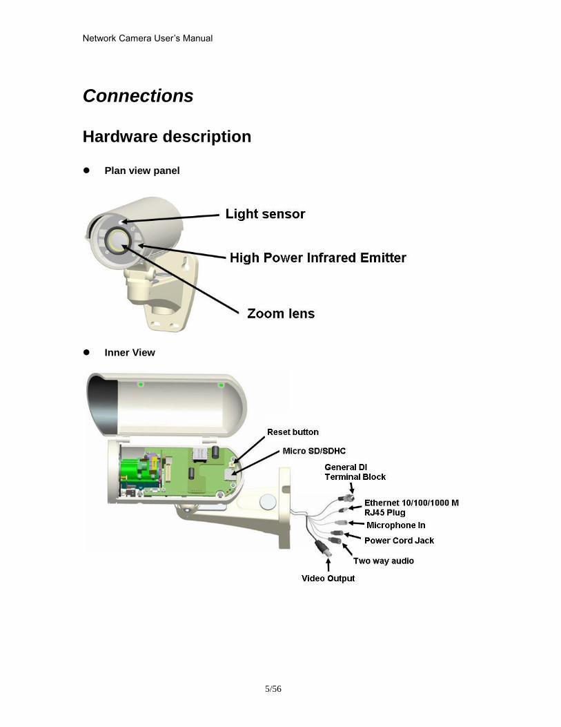
Network Camera Userrsquos Manual
556
Connections
Hardware description
Plan view panel
Inner View
Network Camera Userrsquos Manual
656
Hardware Installation 1 Attach the Network Camera with the included stand
2 Place the Camera fix it onto ceiling or wall Use screws to fix the Network Camera onto the ceiling or wall
3 Power over Ethernet (PoE) Using a PoE-enabled switch The Network Camera is PoE-compliant allowing transmission of power and data via a single Ethernet cable Follow the below illustration to connect the Network Camera to a PoE-enabled switch via Ethernet cable
Network Camera Userrsquos Manual
756
General Connection (without PoE) 1 Connect the camera to a switch via Ethernet cable
2 Connect the power cable from the Network Camera to power outlet
4General IO Terminal Block This Network Camera provides a general IO terminal block which is used to connect external input devices The pin definitions are described below
Network Camera Userrsquos Manual
856
Connect to the Network Camera
Install the IP Finder program When you installed your Network camera on your LAN environment you may install ldquoIP Finderrdquo to discover Network camerarsquos IP address The Administrator must place the product software CD into the CD-ROM drive of the PC running in Microsoft Windows An auto-run program will pop up (If the program is not on auto-run go to the root directory of the software CD and click on ldquoautorunexerdquo)
Click on ldquoSoftware Utilityrdquo item after the window contents changed click on ldquoInstall IP Finderrdquo to run ldquoIP Finderrdquo program
Network Camera Userrsquos Manual
956
ldquoIP Finderrdquo is used to search the IP address of Network Cameras or Video servers on a LAN After searching Video Servers or Network Cameras will be located by the IP Finder
Network Camera Userrsquos Manual
1056
Search Camera
Click search Camera button the program will search for all family network devices on the same LAN After searching the main installer window will pop up Click on the MAC and model name which matches the product label on your device to connect to the Network Camera via Internet Explorer
Network Camera Userrsquos Manual
1156
Setup Camera Auto Install Wizard will be started and that it can auto guide through the installation process Press the ldquoNextrdquo button execute next process For more information please refer to the Network section on page 31
Network Camera Userrsquos Manual
1256
Network Camera Userrsquos Manual
1356
Network Camera Userrsquos Manual
1456
Network Camera Userrsquos Manual
1556
Bonjour program Safari browser supports Bonjour search program the will search for all family network devices on the same LAN
Network Camera Userrsquos Manual
1656
C2mylevel1com (Free DDNS service) 1 When you want to connect the network camera over Internet you can use the service ldquoC2mylevel1comrdquo The ldquoip-discoverycomrdquo is a free DDNS server for this camera Make sure that the router must start UPnP and DHCP server functions You can get the domain name which you wish very easily after registration In Network pagemdashDDNS settings of this camera you just input the host name you want and your e-mail address and click ldquoRegisterrdquo then you can have the hostname for this camera not longer than 20 seconds if the DDNS registration result is OK Then you can connect to this ip camera by httpXXXc2mylevel1com XXX the host name you type The HTTP port (get it automatically by c2mylevel1 server)
User password Default the password is last six number of the MAC To change ldquorootrdquo password at ldquoSecurity configurationrdquo can change the user password This ldquoUser passwordrdquo is entered in the c2mylevel1com Password Note You must set the ports between your router and camera manually if the registration is failed
Network Camera Userrsquos Manual
1756
Initial Access to the Network Camera
(1) For the initial access to the Network Camera in Windows the web browser may prompt for permission to install a new plug-in for the Network Camera This plug-in has been registered for certificate and is used to display the video in the browser
Users may click on to proceed
1 Click ldquoInstallrdquo and ldquoRunrdquo ActiveX controls 2 The video will be displayed
Network Camera Userrsquos Manual
1856
Primary userrsquos capability
Main Screen with Camera View The main page has three parts
1 Configuration functions The camera can be configured using these user interfaces
2 Connection control buttons These buttons provide the remote and local switching stream
3 Camera View What the camera sees Click the configuration in the bottom of left column to link to the configuration page
Configuration functions ldquoClient Settingsrdquo Clicking on this button links you to the client setting pages please check the following session for more details
ldquoConfigurationrdquo Please notes that only the administrator can access it ldquo Languagerdquo Click this button to choose a language for the user interface Language options are available in English traditional Chinese Simplified Chinese Japanese Spanish Portuguese French German Italiano
1
2
3
Network Camera Userrsquos Manual
1956
Camera view On the top of image shows the connecting type of the Network Camera and the current datetime
View capabilities
1 Click this button to capture and save still images The captured images will be
displayed in pop-up window Right-click the image and choose Save Picture As to save it in JPEG format
2 The button selection lets you open a digital zoom and to control the window to
enlarge a specified area in the camera view
3 Click this button to switch to full screen mode Press the ldquoEscrdquo key to switch back to normal mode
4 Click on this button freeze the video and playing when you click again
5 Click on this button stop video output
6 Use this functionyou can record video in your PC by browser directly The files
format will be in MP4
7 Click on this button adjust the audio volume amp Latency
8 Click on this button switch Mute OnOff
9 Click on this button to adjust the Function ldquo2-way audiordquo to be EnableDisable Enable this function request insert an external speaker The server can play sound from the client and receive sound from the environment and send to client
10 Click on this button to adjust the Microphone volume
Network Camera Userrsquos Manual
2056
11 Click on this button switch Microphone Mute OnOff Connection control buttons
1 ldquoConnectionrdquo User can choose Remote or Local mode for best connection quality Proposal Internet environment switch Remote mode
2 ldquoVideo Streamrdquo User can choose stream1 or stream2
Network Camera Userrsquos Manual
2156
Client Setting
1 ldquoIntranet Protocol Optionsrdquo Setting camera in intranet mode of protocol ldquoUDPrdquo Select use UDP protocol connect camera ldquoTCPrdquo Select use TCP protocol connect camera ldquoHTTPrdquo Select use HTTP protocol connect camera
2 ldquoInternet Protocol Optionsrdquo Setting camera in internet mode of protocol ldquoUDPrdquo Select use UDP protocol connect camera ldquoTCPrdquo Select use TCP protocol connect camera ldquoHTTPrdquo Select use HTTP protocol connect camera
3 ldquoRecording optionsrdquo Users can record live video as they are watching by
clicking start MP4 Recording on the main page Here you can specify the storage destination and file name
ldquoFolderrdquo Specify the storage destination for the recorded video files ldquoFile name prefixrdquo Enter the text that will be appended to the front of the video
file name ldquoAdd date and time suffix to file namerdquo Select this option to append the date
and time to the end of the file name
Network Camera Userrsquos Manual
2256
NOTEProtocol Options which allows choices on connection protocol between client and
server There are three protocols choices to optimize your usage ndash UDP TCP HTTP The UDP protocol allows for more real-time audio and video streams However some packets may be lost due to network burst traffic and images may be obscured The HTTP protocol allows for less packet loss and produces a more accurate video display The downside with this protocol is that the real-time effect is worse than that with the UDP protocol The TCP guarantees the complete delivery of streaming data and thus provides better video quality However the real-time effect is not as good as that of the UDP protocol If no special need is required UDP protocol is recommended Generally speaking the client choice will be in the order of UDP rarr HTTP After the Network Camera is connected successfully ldquoProtocol Optionrdquo will indicate the selected protocol The selected protocol will be recorded in the users PC and will be used for the next connection If the network environment is changed or the user wants to let the web browser to detect again manually select the UDP and TCP protocol save and return HOME to re-connect
Network Camera Userrsquos Manual
2356
Definitions in Configuration
Please note that only the Administrator can access the system configuration Each category in the left column will be explained on the following pages
System parameters
1 ldquoGeneral Settingrdquo
(1) ldquoHost namerdquo The text displays the title on the top of the main page
Firmware version
Network Camera Userrsquos Manual
2456
2 ldquoTime Settingrdquo (1) ldquoTime zonerdquo Choose a time zone from the down arrow
(2) ldquoDaylight savingrdquo For summertime It will be one hour ahead
(3) ldquoCurrent Timerdquo Network camera set the current time
(A) ldquoKeep current date and timerdquo Click on this to keep the current date and time of the Network Camera An internal real-time clock maintains the date and time even when the power of the system is turned off
(B) ldquoSync with computer timerdquo Synchronize the date and time in the Network Camera according to the local computer
(C) ldquoManualrdquo Adjust the date and time by the Administrator
(D) ldquoAdjust by NTP serverrdquo Synchronize the time according NTP server over the Internet whenever the Network Camera is switched on It fails if the assigned time-server cannot be found
(a) ldquoNTP serverrdquo Assign the IP address or domain name of the time-server Leaving the text box blank connects the Network Camera to the default time-servers
(b) ldquoUpdate intervalrdquo Select 0 ~ 23 hours update with the time on the NTP server
3 ldquoDI statusrdquo Please go to Application page for setting the DI
Network Camera Userrsquos Manual
2556
Security
Security setting The administrator account name is ldquorootrdquo which is permanent and can not be deleted If you want to add more accounts in the Manage User column please set a password for the ldquorootrdquo account first 1 ldquoChange root passwordrdquo Change the Administratorrsquos password by typing in the new password identically in both text boxes The typed entries will be displayed as asterisks for security purposes After pressing ldquofinishrdquo the web browser will ask the Administrator for the new password to access
2 ldquoManage privilegerdquo You can modify the manage privilege of operators or viewers Check or uncheck the item then click finish to enable the settings
3 ldquoManage userrdquo (1) ldquoAdd a new userrdquo Administrators can add up to 20 user accounts
(A) Input the new userrsquos name and password (B) Select the privilege level for the new user account Click Finish to enable the
setting
(2) ldquoDelete a userrdquo Select an existing user name Click Finish to enable the setting
Network Camera Userrsquos Manual
2656
(3) ldquoUpdate a existing userrdquo Select an existing user name Administrators can modify userrsquos password and privilege Click Finish to enable the setting
Access rights are sorted by user privilege (Administrator Operator and Viewer) Only administrators can access the Configuration page Operators cannot access the Configuration page but can use the URL Commands to get and set the value of parameters Viewers access only the main page for live viewing
Network
Any changes made on this page will restart the system in order to validate the changes Make sure every field is entered correctly before clicking on ldquofinishrdquo
Network Camera Userrsquos Manual
2756
Network Setting ldquoLANrdquo amp ldquoPPPoErdquo The default type is LAN Select PPPoE if using ADSL
1 LAN
The default status is Get IP address automatically This could be tedious to perform software installation whenever the Network Camera starts Therefore once the network is set especially for the IP address should be entered correctly Select Use fixed IP address then the Network Camera will skip installation The Network Camera will automatically restart and operate normally after a power outage You can run IP installer to check the IP address assigned to the Network Camera if the IP address is forgotten or you can use the UPnP function provided by the Network Camera (MS Windows XP provides UPnP function at My Network Place)
(1) ldquoGet IP address automaticallyrdquo (2) ldquoUse fixed IP addressrdquo
- ldquoIP addressrdquo This is necessary for network identification - ldquoSubnet maskrdquo This is used to determine if the destination is in the same subnet The default value is ldquo2552552550rdquo - ldquoDefault routerrdquo This is a gateway used to forward frames to destinations in a different subnet Invalid router setting will fail the transmission to destinations in different subnet - ldquoPrimary DNSrdquo The primary domain name server that translates hostnames into IP addresses - ldquoSecondary DNSrdquo Secondary domain name server backups the Primary DNS - ldquoEnable UPnP presentation amp port forwardingrdquo Enable UPnP ability - ldquoHttp portrdquo This can be typed besides the default Port 80 Once the port is changed the users must make sure the change for the connection is successful For instance when the Administrator changes the HTTP port of the Network Camera which IP address is 192168020 from 80 or 1025 to 65535 the users must type in the web browser ldquohttp1921680208080rdquo instead of ldquohttp192168020rdquo
- ldquoRTSP Portrdquo RTSP port can be typed besides the default Port 554 - ldquoRTP Portrdquo The RTP port can be typed besides the default Port 54
Note Please set Video RTP port in even number after default value port 54 Then
Video RTCP potAudio RTP portAudio RTCP port will automatically set the
values in ascending
- ldquoRTSP Streaming access namesrdquo The RTSP streaming currently supports video only audio only and audiovideo To use the audiovideo stream type the URL asldquortsp613012543liveNsdprdquo
2 PPPoE If using the PPPoE interface you should fill the following settings from ISP
(1) ldquoUser namerdquo The login name of PPPoE account (2) ldquoPasswordrdquo The password of PPPoE account (3) ldquoConfirm passwordrdquo Input password again for confirmation
Network Camera Userrsquos Manual
2856
DDNS Setting 1 ldquoEnable DDNSrdquo This option turns on the DDNS function
2 ldquoip-discoveryrdquo In the Register column fill in the Host name (xxxx ip-discovery) Email Key and Confirm Key then click Register After a host name has been successfully created a success message will be displayed in the DDNS Registration Result column and messaging E-mail
3 ldquo3rd party DDNSrdquo This is enable or disable 3rd party DDNS 4 ldquoProviderrdquo The provider list contains hosts that provide DDNS services Please connect to the service providerrsquos website to make sure the service charges
5 ldquoHost Namerdquo If the User wants to use DDNS service this field must be filled Please input the hostname that is registered in the DDNS server
6 ldquoUser namerdquo The Username or E-mail field is necessary for logging in the DDNS server or notify the User of the new IP address Note when this field is input as ldquoUser namerdquo the following field must be input as ldquoPasswordrdquo
7 ldquoPasswordrdquo Please input the password or key to get the DDNS service
8 ldquofinishrdquo Click on this button to save modify settings for the DDNS service
Network Camera Userrsquos Manual
2956
Access list
Access list setting 1 How to control access permission by verifying the client PCrsquos IP
address General Settings General Settings
Add a rule to configure an AllowedDenied list Click Add to add a rule
Network Camera Userrsquos Manual
3056
to AllowedDenied list There are three types of rules for user to set up ldquoSinglerdquo This rule allows the user to add an IP address to the AllowedDenied list For example
ldquoNetworkrdquo This rule allows the user to assign a network address and corresponding subnet mask to the AllowDeny List The IP address is written in the CIDR format For example
Network Camera Userrsquos Manual
3156
ldquoRangerdquo This rule allows the user to assign a range of IP addresses to the AllowDeny List This rule is only applied to IPv4 For example
Network Camera Userrsquos Manual
3256
Audio and Video setting
Network Camera Userrsquos Manual
3356
General Setting 1 ldquoColor moderdquo Select use color or monochrome video display
2 ldquoVideo orientationrdquo The orientation of video
(1) ldquoFliprdquo Vertically rotate the video
(2) ldquoMirrorrdquo Horizontally rotates the video
3 ldquoEnvironmentrdquo The orientation of video
(1) ldquoindoorrdquo This option is usually selected when the Network Camera is placed in indoor environments
(2) ldquooutdoorrdquo This option is usually selected when the Network Camera is placed in outdoor environments
4 ldquoPower freqrdquo Select 50 Hz or 60Hz power line frequency
The fluorescent light will flash according to the power line frequency that
depends on local utility Change the frequency setting to eliminate uncomfortable flash image when the light source is only fluorescent light
Video Setting 1 ldquoContrastrdquo Adjust the image contrast level which ranges from -5 to +5 The default value is set to 0
2 ldquoBrightnessrdquo Adjust the image brightness level which ranges from -5 to +5 The default value is set to 0
3 ldquoSaturationrdquo Adjust the image saturation level which ranges from -5 to +5 The default value is set to 0
4 ldquoSharpnessrdquo Adjust the image sharpness level which ranges from -5 to +5 The default value is set to 0
5 ldquoEVrdquo Exposure value represent the expected target value of the luminance of
the weighting result of AE windows in the image and its tolerance as offset
6 ldquoGainrdquo In the slide bar of Gain there are also two sliders which represent the
limitations to control the maximum gain value and the minimum one respectively Normally the minimum value is to 1x for better quality
Network Camera Userrsquos Manual
3456
Exposure setting Here it provides 3 mode Auto Backlight and Customized Auto and
Backlight modes are 2 default settings for general purpose and backlight scene
respectively
Customized mode relates to the grid window above can be pointed on for
interesting areas Within the mode Customized 1615 grids windows can be chosen to match wherewhat you are interested in Push down left-button of mouse and drag to draw the grids for interesting areas or push down right-button of mouse and drag to clean the grids for insignificant areas
ldquoTarget Luminance and Offsetrdquo
These two slide bar Target Luminance and Offset represent the expected
target value of the luminance of the weighting result of AE windows in the image and its tolerance as offset For example target luminance is set to 100 and target offset is set to 20 that means the average luminance of the AE window should be in the range from 80 to 120 (100plusmn(10 When the actual luminance does not meet this range the AE function will adjust shutter and gain to meet it as possible In some extreme cases it cannot reach the target because the environment is too bright or dark When the environment is not consistent eg with big moving objects and the offset is too narrow the AE will act more frequently that will cause the background of view inconsistent The offset value is recommended to set 15~25 of target luminance
Network Camera Userrsquos Manual
3556
ldquoGainrdquo
In the slide bar of Gain there are also two sliders which represent the limitations
to control the maximum gain value and the minimum one respectively Normally the minimum value is to 1x for better quality It is not allowed if the maximum slider and the minimum one are set to the same value without adjustable interval Besides the noise will be increased if the actual gain is too large When the max slider is dragged over sensors max gain the slide bar will become deep blue to represent it will apply Mozart 3s digital gain which extend the max gain for very low light
ldquoShutter Speedrdquo
There are 2 fields minimal and maximal time for the range of Shutter Speed
The precision of the parameter is 11000000 sec but it is NOT actual precision of the shutter speed of the sensor The actual precision of the shutter speed depends on each sensorrsquos specification Here it will be rounded to approach sensorrsquos effective exposure time To avoid flickering or banding phenomenon under fluorescent light the actual shutter speed will be locked at 1120 160
130 if Power Line Frequency is 60Hz or 1100 150 125 if Power Line
Frequency is 50Hz The setting of Power Line Frequency is on the sub-tab Video
and Audio The exposure may not be stable if the maximum value and the minimum one are set to the same value without adjustable interval Besides the frame rate will drop down if the actual shutter speed is too slow to meet expected frame rate
Noise reduction
Provides 2D and 3D features
Wide Dynamic Range Enable Wide Dynamic Range auto in different level to improve the exposure when both bright and dark areas simultaneously in the field of view of the camera The default is off
Infrared Led Setting 1 ldquoInfrared LED Controlrdquo IR led for Day and Night (Option) User can turn onoff the built-in IR led This function is very useful under low illumination environment
(1) ldquoAutordquo Select IR sensitivity from 0 to 4
(2) ldquoManualrdquo Turn onoff the IR led manually
- ldquoTurn onrdquo Turn on led - ldquoTurn offrdquo Turn off led
2 ldquoLow lux moderdquo The video quality will be improved when the camera is in low lux environment (1) ldquoDisable dark moderdquo Disable low lux mode
(2) ldquoEnable dark moderdquo Enable low lux mode
Network Camera Userrsquos Manual
3656
Video output Setting 1 ldquovideo outputrdquo Can switch between NTSC and PAL
Audio Setting 1 ldquoMuterdquo Audio mute
2 ldquoMicrophone rdquo External microphone
3 ldquoMic Volumerdquo Adjust microphone volume which ranges from 1 to 46
Video record
Schedule mode
(1) ldquoEvery dayrdquo EnableDisable every day application
(2) ldquoWeek dayrdquo EnableDisable week day application
(3)ldquoSelected dayrdquo EnableDisable selected day application
Schedule information
(1) Enter the ldquoStart timerdquo and ldquoStop timerdquo for day mode Note that the time format is [hhmm] and is expressed in 24-hour clock time By default the start and end time of day mode are set to 010000 and 235959
Network Camera Userrsquos Manual
3756
(2)ldquoSunrdquoldquoMonrdquoldquoTuerdquoldquoWedrdquoldquoThurdquoldquoFrirdquoldquoSatrdquo Select the days of the week to perform the application
(3) ldquoStart dayrdquo and ldquoStart timerdquo as the start timing the time ldquoEnd dayrdquo and ldquoEnd timerdquo as the end timing the time
(4) ldquoEnable cyclic recordingrdquo The cyclic recording function is enabled during the transaction stage when a storage space is full and the incoming streaming data is about to overwrite the previously saved videos
Record parameters (1)Source Select a stream for the recording source
(2)Recording interval Select the recording time interval
(3)Prefix file name You can setting the file name and enable or disable to add the date and time on file name
Response mode There are two choices of server types available NAS SD Card Select the item to display the detailed configuration options
(1)rdquoNASrdquo
--ldquoNAS server addressrdquo Enter IP address of the NAS server
--ldquoNAS shared directoryrdquo Enter the NAS shared directory path --ldquoWorkgrouprdquo Enter the NAS workgroup parameter --ldquoUser accountrdquo Enter the login name of the NAS account --ldquoUser passwordrdquo Enter the password of the NAS account Note Video record with the Application must be set to the same shared directory
path If you would like do detail recording settings or multi-channel recording please install bundled 64CH recording software in CD
Network Camera Userrsquos Manual
3856
Stream
Audio codec setting
(1)ldquoAudio codec typerdquo There are two choices of audio codec types
available rdquoAMRrdquo ldquoAACrdquo and rdquoG711rdquo
(2) ldquoBit raterdquo -- ldquoAMRrdquo The bit rates are selectable at the following rates
47505150590067007400795010200 and 12200
-- ldquoAACrdquo The bit rates are selectable at the following rates 8Kbps16Kbps 24Kbps and 32Kbps
-- ldquoG711rdquo pcmu and pcma
Video codec setting (1) ldquoSelect Streamrdquo The Network Camera supports ldquoStream 1rdquoand ldquoStream 2rdquo
(2) ldquoVideo codecrdquo The Network Camera supports three kind of video compression mode ldquoH264rdquo or ldquoMPEG4rdquo or ldquoMJPEGrdquo User can choose one of
Network Camera Userrsquos Manual
3956
these compression modes based on requirement or application
(3) ldquoVideo sizerdquo Click the down arrow to choose the quality of image (1920x1080 1280x1024 1280x800 640x480 320x240 176x144)
(4) ldquoConnection typerdquo User can select this button to choose the better video amp links quality (Internet mode or Intranet mode)
(5) ldquoFrame raterdquo This limits the maximal refresh frame rate per second Set the frame rate higher for a smoother video quality
(6) ldquoIntra frame periodrdquo Determine how often to plant an ldquoI framerdquo The shorter the duration the more likely you will get a better video quality but at the cost of higher network bandwidth consumption
(7) ldquoVideo Quality typerdquo Setting optimizes bandwidth utilization and video quality
-- ldquoConstant bit raterdquo User can adjust the video quality from 20 Kbps to 12 Mbps
-- ldquoFixed qualityrdquo user can select from lowest quality to get best quality according The ldquoQualityrdquo are selectable at the following rates From 1 to 20
Snapshot and time display setting Adjust the photo size specifications and choose whether to mark time on the video and photo
Network Camera Userrsquos Manual
4056
Application
Schedule mode
(1) ldquoEvery dayrdquo EnableDisable every day application
(2) ldquoWeek dayrdquo EnableDisable week day application
(3) ldquoSelected dayrdquo EnableDisable selected day application
Schedule information (1) Enter the ldquoStart timerdquo and ldquoStop timerdquo for day mode
Note that the time format is [hhmmss] and is expressed in 24-hour clock time By default the start and end time of day mode are set to 010000 and 235959
(2) ldquoSunrdquoldquoMonrdquoldquoTuerdquoldquoWedrdquoldquoThurdquoldquoFrirdquoldquoSatrdquo Select the days of the week to perform the application
(3) ldquoStart dayrdquo and ldquoStart timerdquo as the start timing the time ldquoEnd dayrdquo and ldquoEnd timerdquo as the end timing the time
Trigger mode
(1) ldquoVideo motion detectionrdquo EnableDisable video motion application (2) ldquoPeriodicallyrdquo This option allows the Network Camera to trigger
periodically for every other defined minute
Network Camera Userrsquos Manual
4156
(3) ldquoDigital inputrdquo This option allows the Network Camera to use an external digital input device or sensor as a trigger source Depending on your application there are many choices of digital input devices on the market which helps to detect changes in temperature vibration sound and light etc
parameters
(1) ldquoMotion parametersrdquo Higher sensitivity and small threshold will allow easier motion detection
(2) ldquoPeriod parametersrdquo This option allows the Network Camera to trigger periodically for every other defined seconds Up to 999 seconds are allowed
(3) ldquoDigital input parametersrdquo Select the digital input type and set trigger time
Media mode There are four choices of media types available ldquoSnapshotrdquo ldquoMessagerdquo ldquoRecord(Motion Detection only)rdquo and ldquoSystem logrdquo
Snapshot amp Record file setting You can setting the file name and enable or disable to add the date and time on file name Can setting the digital output duration seconds Response mode There are four choices of server types available Email FTP NAS and SD Card storage Select the item to display the detailed configuration options
(1)ldquoEmailrdquo -- ldquoEmail security moderdquo If your SMTP server requires a secure connection (SSL or TLS) check This server requires a secure connection (SSL or TLS) -- ldquoSender emailrdquo address Enter the email address of the sender -- ldquoRecipient emailrdquo address Enter the email address of the recipient
-- ldquoServer addressrdquo Enter the domain name or IP address of the email server
--ldquoUser namerdquo Enter the user name of the email account if necessary
--ldquoPasswordrdquo Enter the password of the email account if necessary
--ldquoServer portrdquo The default mail server port is set to 25 You can also manually set another port
(2)rdquoFTPrdquo -- ldquoServer addressrdquo Enter the domain name or IP address of the FTP server
-- ldquoServer portrdquo By default the FTP server port is set to 21
-- ldquoUser namerdquo Enter the login name of the FTP account
-- ldquoPasswordrdquo Enter the password of the FTP account
-- ldquoFTP folder namerdquo Enter the folder where the media file will be placed If the folder name does not exist the Network Camera will create one on the FTP server
(3)rdquoHTTP rdquo
-- ldquoURLrdquo Enter the URL of the HTTP server
-- ldquoUser accountrdquo Enter the user name if necessary -- ldquoUser passwordrdquo Enter the password if necessary
(4)rdquoNASrdquo --ldquoNAS server addressrdquo Enter IP address of the NAS server
--ldquoNAS shared directoryrdquo Enter the NAS shared directory path
Network Camera Userrsquos Manual
4256
--ldquoWorkgrouprdquo Enter the NAS workgroup parameter --ldquoUser accountrdquo Enter the login name of the NAS account --ldquoUser passwordrdquo Enter the password of the NAS account Note Video record with the Application must be set to the same shared directory
path If you would like do detail recording settings or multi-channel recording please install bundled 64CH recording software in CD
Network Camera Userrsquos Manual
4356
Storage
Manage the storage device
S torage Status Here show the storage device information
NAS server setting
1
2
3
Network Camera Userrsquos Manual
4456
(1) ldquoNAS Host namerdquo Choose and input the NAS Host name of this camera
(2) ldquoWorkgrouprdquo Input the name of Workgroup You can see the NAS Host name you input in the same workgroup with your PC Then you can connect to this device and download the files easily from SD card which is inserted to this camera
File operation Move the mouse over the file Press the mouse right button that Right-click menu is displayed You can delete files Move the mouse over the directory Press the mouse left button that the file structure expand Press the mouse right button that Right-click menu is displayed You can choose upload or delete files NOTEAllow the user to upload or delete files when the storage device is not write-
protected If the SD card canrsquot be detected please link to the following URL httpwwwsdcardorgconsumersformatter to download the ldquoSD Formatter Kitrdquo formatting your SD card
Network Camera Userrsquos Manual
4556
Syslog
The Network camera supports log the system messages on remote server The protocol is compliant to RFC 3164 If you have external Linux server with sys log service use ldquo-rrdquo option to turn on the facility for receiving log from remote machine Or you can use some software on Windows that is compliant to RFC 3164 An example is Kiwi Syslog Daemon Visit httpwwwkiwisyslogcomkiwi-syslog-daemon-overview Check ldquoSetuprdquo and ldquoEnablerdquo then input the ldquoIP addressrdquo and ldquoportrdquo number of the log server to enable the remote log facility In the ldquoCurrent logrdquo it displays the current system log file The content of the log provides useful information about configuration and connection after system boot- up
ldquofinishrdquo Click on this button to save modify settings
Network Camera Userrsquos Manual
4656
Status and Parameters
User can find a lot of information about the system such as ldquoUpnp port forwardingrdquo
ldquoTraversing NATrdquo ldquoPublic IPrdquo and so on User also can get the number of current viewer of the Network Camera here
Network Camera Userrsquos Manual
4756
Maintenance
1 ldquoReboot systemrdquo The ldquoRebootrdquo button will reboot the Network Camera Itrsquos useful while the Network Camera got problem 2 ldquoRestore systemrdquo Click on ldquoRestorerdquo button on the configuration page to restore the factory default settings Restore all settings to factory default except settings in ldquoNetwork type rdquo and ldquoRoot Passwordrdquo The system will restart and require the installer program to set up the network again
3 ldquoCalibraterdquo Recalibrate the auto focus position to the default range to recover the tolerance caused by some external forces 4 ldquoExportImport filerdquo -- Export setting backup file Click to export all parameters for the device and user-defined scripts
-- Upload setting backup file Click Browsehellip to upload a setting backup file Please note that the model and firmware version of the device should be the same as the setting backup file If you have set up a fixed IP or other special settings for your device it is not suggested to upload a settings backup file
4 ldquoUpgrade firmwarerdquo Select the firmware file and click upgrade button Please be aware that you should not turn off the power during updating the firmware and wait for finish message
Network Camera Userrsquos Manual
4856
Warning The upgrade firmware procedure cannot be interrupted If the power
andor network connection are broken during the procedure it might possibly cause serious damage to the Network Camera
Note When upgrade firmware please wait for 120~210 seconds and then you can connect to Network Camera again The system will restart and require the installer program to set up the network again
Network Camera Userrsquos Manual
4956
Appendix
A Troubleshooting amp Frequently Asked Questions Q1 Status led does not light up
A1 First make sure that「ConfigurationgtSystemgtTurn off the LED indicator」is disabled
If it is check the item and the led should light up Second if red led does not light up please check that the power adapter in the package is plugged correctly And last if green led does not light up please check that category 5 UTP cable is plugged correctly If the problem is still not solved please contact your dealer for further help
Q2 What kind of Ethernet cable is used by network camera
A2 The network Camera uses Category 5 UTP cable allowing 10 andor 100 Base-T networking
Q3 The Network Camera will be installed and work if a firewall exists on
the network
A3 There are two way to set up the IP camera at Internet (1) By UPnP Port Forwarding 1 Select an IP router It must support UPnP port forwarding and enable this function
first
2 Connect camera RJ45 cable to IP router and the router is also connected to Internet
3 Plug power cord to camera
4 Go to camera Network page Enable UPnP port forwarding
5 Check camera status we can see the ports had been successfully opened
Network Camera Userrsquos Manual
5056
6Type IP address8080 at browser Then you can see camera through Internet
7You can also type the ddns name at below label of camera on browser URL field For example you may type ah00001ip-discoverycom8080 (2) By Setting Port Forwarding Manually 1 Select a router Set the port forwarding as following
Network Camera Userrsquos Manual
5156
PS Port 80 is HTTP Port port 53 is stream port port 554 is RTSP port and port 443 is HTTPS port 2Go to camera Network page Disable UPnP port forwarding function
Network Camera Userrsquos Manual
5256
3 Type IP address at browser Then you can see camera through Internet
4 You can also type the ddns name at below label of camera on browser URL field For example you may type ah00001ip-discoverycom
Note The firewall software at PC may block the transfer of network camera Please remove or stop the kind software
Q4 How can I find the network camera in the local area network
A4 By using the IP Finder2 program or using UPnP to find it
Q5 IP Finder2 program cannot find Network Camera in the local area
network at first time
A5 Make sure the subnet of network camera is same as your PC If the local area network supports DHCP the camera is ldquoGet IP address automaticallyrdquo in the ldquoNetworkrdquo page default If the local area network does not support DHCP change your PC IP address to ldquo1921680xxxrdquo
Network Camera Userrsquos Manual
5356
Q6 How can I restore the network camera to default value
A6 Use a gem clip to press on the inside button Network camera begins to restore default value You can also press the button ldquoFactoryrdquo in ldquoMaintenancerdquo page to restore the default value
Q7 I cannot play the recorded video file
A7 Install the audio codec in the CD and use the Windows Media Player 10 or later to play the ASF or AVI file recorded by the network camera
Q8 Infrared led does not light up
A8 Check「ConfigurationgtAudio and VideogtInfrared LED Control」 is ldquoAutordquo or
ldquoManual》Turn onrdquo
Q9 The network camera cannot focus accurately
A9 (1) The lens is dirty or dust is attached Clean the lens with lens cleaner And then adjust the camera focus manually (2) The image may be out of focus If the object is too near move the object away from Network Camera
Q10 The cover of network camera is warm Is it normal
A10 Network camera is a precision device The internal material has the operational temperature and it is normal when user touch the cover feels warm It is recommended to put the network camera at aired place and not put at any other device
Q11 The process of upgrade firmware abort
A11 Contact your dealer for further help
Q12 Cannot access the login page and other web pages of Network
Network Camera Userrsquos Manual
5456
Camera from Internet Explorer
A12 bull May be due to the network cable Try correcting your network cable and configuration Test the network interface by connecting a local computer to the Network Camera via a crossover cable bull Make sure the Internet connection and setting is ok bull Make sure enter the IP address of Internet Explorer is correct If Network Camera has a dynamic address it may have changed since you last checked it bull Network congestion may prevent the web page appearing quickly Wait for a while The IP address and Subnet Mask of the PC and Network Camera must be in the same class of the private IP address on the LAN bull Make sure the http port used by the Network Camera default=80 is forward to the Network Camerarsquos private IP address bull The port number assigned in your Network Camera might not be available via Internet Check your ISP for available port bull The proxy server may prevent you from connecting directly to Network Camera set up not to use the proxy server bull Confirm that Default Gateway address is correct bull The router needs Port Forwarding feature Refer to your routers manual for details bull Packet Filtering of the router may prohibit access from an external network Refer to your routers manual for details bull Access Network Camera from the Internet with the global IP address of the router and port number of Network Camera bull Some routers reject the global IP address to access Network Camera on the same LAN Access with the private IP address and correct port number of Network Camera bull When you use DDNS you need to set Default Gateway and DNS server address bull If itrsquos not working after above procedure reset Network Camera to default setting and installed it again bull Maybe the IP Address of the Network Camera is already being used by another device or computer bull If the problem is not solved the Network Camera might be faulty Contact your dealer for further help
Network Camera Userrsquos Manual
5556
B Technical specifications
- System RAM 4G bit DDRⅢ
ROM 16MB Flash ROM
- Camera specification 127 inch color CMOS sensor Resolution 1920x1080 10LuxF20 AGC AWB AEC
- Infrared Led High power IR Leds 25~30 M visible AutoManual mode
- Lens 3X optical zoom lens auto iris auto focus f = 28~ 12mm F18 Fov(D) 136deg ~ 39deg
- Protocol TCPIP HTTPUDP SMTP FTP DDNS UPnP Telnet NTP PPPoE RTSP RTPRTCPDHCP and DNS
- Video Resolution Up to 30 frames at 176x144 Up to 30 frames at 320x240 Up to 30 frames at 640x480 Up to 30 frames at 1280x800 Up to 30 frames at 1280x1024 Up to 30 frames at 1920x1080
- Algorithm supported H264MPEG4MJPEG dual codec for streaming video JPEG for still image
- Audio AMRAACG711 External MIC input 2-way audio
- Physical 10 baseT100 baseT and 1000 baseT Fast
Ethernet auto negotiation
- Power Input 100-240VAC 5060Hz 07A Output 12VDC 15A Consumption Max 12 W Support 8023af compliant Power over Ethernet
- EMI amp Safety CE FCC
- Dimension Length 165mm Diameter 75mm
- Operating Environment Temperature -20 ~ 50
Humidity 85 RH
- Weight NET 600g With bracket 800g
Network Camera Userrsquos Manual
5656
Notification of Compliance Appendix C
Europe - EU Declaration of Conformity
For complete DoC please visit httpgloballevel1comdownloadsphpaction=init
GPL License Agreement GPL may be included in this product to view the GPL license agreement goes to httpdownloadlevel1comlevel1gplGPLpdf For GNU General Public License (GPL) related information please visit httpgloballevel1comdownloadsphpaction=init
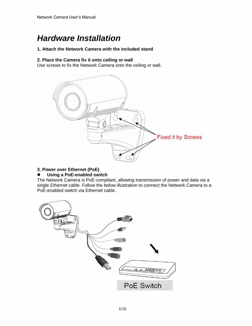
Network Camera Userrsquos Manual
656
Hardware Installation 1 Attach the Network Camera with the included stand
2 Place the Camera fix it onto ceiling or wall Use screws to fix the Network Camera onto the ceiling or wall
3 Power over Ethernet (PoE) Using a PoE-enabled switch The Network Camera is PoE-compliant allowing transmission of power and data via a single Ethernet cable Follow the below illustration to connect the Network Camera to a PoE-enabled switch via Ethernet cable
Network Camera Userrsquos Manual
756
General Connection (without PoE) 1 Connect the camera to a switch via Ethernet cable
2 Connect the power cable from the Network Camera to power outlet
4General IO Terminal Block This Network Camera provides a general IO terminal block which is used to connect external input devices The pin definitions are described below
Network Camera Userrsquos Manual
856
Connect to the Network Camera
Install the IP Finder program When you installed your Network camera on your LAN environment you may install ldquoIP Finderrdquo to discover Network camerarsquos IP address The Administrator must place the product software CD into the CD-ROM drive of the PC running in Microsoft Windows An auto-run program will pop up (If the program is not on auto-run go to the root directory of the software CD and click on ldquoautorunexerdquo)
Click on ldquoSoftware Utilityrdquo item after the window contents changed click on ldquoInstall IP Finderrdquo to run ldquoIP Finderrdquo program
Network Camera Userrsquos Manual
956
ldquoIP Finderrdquo is used to search the IP address of Network Cameras or Video servers on a LAN After searching Video Servers or Network Cameras will be located by the IP Finder
Network Camera Userrsquos Manual
1056
Search Camera
Click search Camera button the program will search for all family network devices on the same LAN After searching the main installer window will pop up Click on the MAC and model name which matches the product label on your device to connect to the Network Camera via Internet Explorer
Network Camera Userrsquos Manual
1156
Setup Camera Auto Install Wizard will be started and that it can auto guide through the installation process Press the ldquoNextrdquo button execute next process For more information please refer to the Network section on page 31
Network Camera Userrsquos Manual
1256
Network Camera Userrsquos Manual
1356
Network Camera Userrsquos Manual
1456
Network Camera Userrsquos Manual
1556
Bonjour program Safari browser supports Bonjour search program the will search for all family network devices on the same LAN
Network Camera Userrsquos Manual
1656
C2mylevel1com (Free DDNS service) 1 When you want to connect the network camera over Internet you can use the service ldquoC2mylevel1comrdquo The ldquoip-discoverycomrdquo is a free DDNS server for this camera Make sure that the router must start UPnP and DHCP server functions You can get the domain name which you wish very easily after registration In Network pagemdashDDNS settings of this camera you just input the host name you want and your e-mail address and click ldquoRegisterrdquo then you can have the hostname for this camera not longer than 20 seconds if the DDNS registration result is OK Then you can connect to this ip camera by httpXXXc2mylevel1com XXX the host name you type The HTTP port (get it automatically by c2mylevel1 server)
User password Default the password is last six number of the MAC To change ldquorootrdquo password at ldquoSecurity configurationrdquo can change the user password This ldquoUser passwordrdquo is entered in the c2mylevel1com Password Note You must set the ports between your router and camera manually if the registration is failed
Network Camera Userrsquos Manual
1756
Initial Access to the Network Camera
(1) For the initial access to the Network Camera in Windows the web browser may prompt for permission to install a new plug-in for the Network Camera This plug-in has been registered for certificate and is used to display the video in the browser
Users may click on to proceed
1 Click ldquoInstallrdquo and ldquoRunrdquo ActiveX controls 2 The video will be displayed
Network Camera Userrsquos Manual
1856
Primary userrsquos capability
Main Screen with Camera View The main page has three parts
1 Configuration functions The camera can be configured using these user interfaces
2 Connection control buttons These buttons provide the remote and local switching stream
3 Camera View What the camera sees Click the configuration in the bottom of left column to link to the configuration page
Configuration functions ldquoClient Settingsrdquo Clicking on this button links you to the client setting pages please check the following session for more details
ldquoConfigurationrdquo Please notes that only the administrator can access it ldquo Languagerdquo Click this button to choose a language for the user interface Language options are available in English traditional Chinese Simplified Chinese Japanese Spanish Portuguese French German Italiano
1
2
3
Network Camera Userrsquos Manual
1956
Camera view On the top of image shows the connecting type of the Network Camera and the current datetime
View capabilities
1 Click this button to capture and save still images The captured images will be
displayed in pop-up window Right-click the image and choose Save Picture As to save it in JPEG format
2 The button selection lets you open a digital zoom and to control the window to
enlarge a specified area in the camera view
3 Click this button to switch to full screen mode Press the ldquoEscrdquo key to switch back to normal mode
4 Click on this button freeze the video and playing when you click again
5 Click on this button stop video output
6 Use this functionyou can record video in your PC by browser directly The files
format will be in MP4
7 Click on this button adjust the audio volume amp Latency
8 Click on this button switch Mute OnOff
9 Click on this button to adjust the Function ldquo2-way audiordquo to be EnableDisable Enable this function request insert an external speaker The server can play sound from the client and receive sound from the environment and send to client
10 Click on this button to adjust the Microphone volume
Network Camera Userrsquos Manual
2056
11 Click on this button switch Microphone Mute OnOff Connection control buttons
1 ldquoConnectionrdquo User can choose Remote or Local mode for best connection quality Proposal Internet environment switch Remote mode
2 ldquoVideo Streamrdquo User can choose stream1 or stream2
Network Camera Userrsquos Manual
2156
Client Setting
1 ldquoIntranet Protocol Optionsrdquo Setting camera in intranet mode of protocol ldquoUDPrdquo Select use UDP protocol connect camera ldquoTCPrdquo Select use TCP protocol connect camera ldquoHTTPrdquo Select use HTTP protocol connect camera
2 ldquoInternet Protocol Optionsrdquo Setting camera in internet mode of protocol ldquoUDPrdquo Select use UDP protocol connect camera ldquoTCPrdquo Select use TCP protocol connect camera ldquoHTTPrdquo Select use HTTP protocol connect camera
3 ldquoRecording optionsrdquo Users can record live video as they are watching by
clicking start MP4 Recording on the main page Here you can specify the storage destination and file name
ldquoFolderrdquo Specify the storage destination for the recorded video files ldquoFile name prefixrdquo Enter the text that will be appended to the front of the video
file name ldquoAdd date and time suffix to file namerdquo Select this option to append the date
and time to the end of the file name
Network Camera Userrsquos Manual
2256
NOTEProtocol Options which allows choices on connection protocol between client and
server There are three protocols choices to optimize your usage ndash UDP TCP HTTP The UDP protocol allows for more real-time audio and video streams However some packets may be lost due to network burst traffic and images may be obscured The HTTP protocol allows for less packet loss and produces a more accurate video display The downside with this protocol is that the real-time effect is worse than that with the UDP protocol The TCP guarantees the complete delivery of streaming data and thus provides better video quality However the real-time effect is not as good as that of the UDP protocol If no special need is required UDP protocol is recommended Generally speaking the client choice will be in the order of UDP rarr HTTP After the Network Camera is connected successfully ldquoProtocol Optionrdquo will indicate the selected protocol The selected protocol will be recorded in the users PC and will be used for the next connection If the network environment is changed or the user wants to let the web browser to detect again manually select the UDP and TCP protocol save and return HOME to re-connect
Network Camera Userrsquos Manual
2356
Definitions in Configuration
Please note that only the Administrator can access the system configuration Each category in the left column will be explained on the following pages
System parameters
1 ldquoGeneral Settingrdquo
(1) ldquoHost namerdquo The text displays the title on the top of the main page
Firmware version
Network Camera Userrsquos Manual
2456
2 ldquoTime Settingrdquo (1) ldquoTime zonerdquo Choose a time zone from the down arrow
(2) ldquoDaylight savingrdquo For summertime It will be one hour ahead
(3) ldquoCurrent Timerdquo Network camera set the current time
(A) ldquoKeep current date and timerdquo Click on this to keep the current date and time of the Network Camera An internal real-time clock maintains the date and time even when the power of the system is turned off
(B) ldquoSync with computer timerdquo Synchronize the date and time in the Network Camera according to the local computer
(C) ldquoManualrdquo Adjust the date and time by the Administrator
(D) ldquoAdjust by NTP serverrdquo Synchronize the time according NTP server over the Internet whenever the Network Camera is switched on It fails if the assigned time-server cannot be found
(a) ldquoNTP serverrdquo Assign the IP address or domain name of the time-server Leaving the text box blank connects the Network Camera to the default time-servers
(b) ldquoUpdate intervalrdquo Select 0 ~ 23 hours update with the time on the NTP server
3 ldquoDI statusrdquo Please go to Application page for setting the DI
Network Camera Userrsquos Manual
2556
Security
Security setting The administrator account name is ldquorootrdquo which is permanent and can not be deleted If you want to add more accounts in the Manage User column please set a password for the ldquorootrdquo account first 1 ldquoChange root passwordrdquo Change the Administratorrsquos password by typing in the new password identically in both text boxes The typed entries will be displayed as asterisks for security purposes After pressing ldquofinishrdquo the web browser will ask the Administrator for the new password to access
2 ldquoManage privilegerdquo You can modify the manage privilege of operators or viewers Check or uncheck the item then click finish to enable the settings
3 ldquoManage userrdquo (1) ldquoAdd a new userrdquo Administrators can add up to 20 user accounts
(A) Input the new userrsquos name and password (B) Select the privilege level for the new user account Click Finish to enable the
setting
(2) ldquoDelete a userrdquo Select an existing user name Click Finish to enable the setting
Network Camera Userrsquos Manual
2656
(3) ldquoUpdate a existing userrdquo Select an existing user name Administrators can modify userrsquos password and privilege Click Finish to enable the setting
Access rights are sorted by user privilege (Administrator Operator and Viewer) Only administrators can access the Configuration page Operators cannot access the Configuration page but can use the URL Commands to get and set the value of parameters Viewers access only the main page for live viewing
Network
Any changes made on this page will restart the system in order to validate the changes Make sure every field is entered correctly before clicking on ldquofinishrdquo
Network Camera Userrsquos Manual
2756
Network Setting ldquoLANrdquo amp ldquoPPPoErdquo The default type is LAN Select PPPoE if using ADSL
1 LAN
The default status is Get IP address automatically This could be tedious to perform software installation whenever the Network Camera starts Therefore once the network is set especially for the IP address should be entered correctly Select Use fixed IP address then the Network Camera will skip installation The Network Camera will automatically restart and operate normally after a power outage You can run IP installer to check the IP address assigned to the Network Camera if the IP address is forgotten or you can use the UPnP function provided by the Network Camera (MS Windows XP provides UPnP function at My Network Place)
(1) ldquoGet IP address automaticallyrdquo (2) ldquoUse fixed IP addressrdquo
- ldquoIP addressrdquo This is necessary for network identification - ldquoSubnet maskrdquo This is used to determine if the destination is in the same subnet The default value is ldquo2552552550rdquo - ldquoDefault routerrdquo This is a gateway used to forward frames to destinations in a different subnet Invalid router setting will fail the transmission to destinations in different subnet - ldquoPrimary DNSrdquo The primary domain name server that translates hostnames into IP addresses - ldquoSecondary DNSrdquo Secondary domain name server backups the Primary DNS - ldquoEnable UPnP presentation amp port forwardingrdquo Enable UPnP ability - ldquoHttp portrdquo This can be typed besides the default Port 80 Once the port is changed the users must make sure the change for the connection is successful For instance when the Administrator changes the HTTP port of the Network Camera which IP address is 192168020 from 80 or 1025 to 65535 the users must type in the web browser ldquohttp1921680208080rdquo instead of ldquohttp192168020rdquo
- ldquoRTSP Portrdquo RTSP port can be typed besides the default Port 554 - ldquoRTP Portrdquo The RTP port can be typed besides the default Port 54
Note Please set Video RTP port in even number after default value port 54 Then
Video RTCP potAudio RTP portAudio RTCP port will automatically set the
values in ascending
- ldquoRTSP Streaming access namesrdquo The RTSP streaming currently supports video only audio only and audiovideo To use the audiovideo stream type the URL asldquortsp613012543liveNsdprdquo
2 PPPoE If using the PPPoE interface you should fill the following settings from ISP
(1) ldquoUser namerdquo The login name of PPPoE account (2) ldquoPasswordrdquo The password of PPPoE account (3) ldquoConfirm passwordrdquo Input password again for confirmation
Network Camera Userrsquos Manual
2856
DDNS Setting 1 ldquoEnable DDNSrdquo This option turns on the DDNS function
2 ldquoip-discoveryrdquo In the Register column fill in the Host name (xxxx ip-discovery) Email Key and Confirm Key then click Register After a host name has been successfully created a success message will be displayed in the DDNS Registration Result column and messaging E-mail
3 ldquo3rd party DDNSrdquo This is enable or disable 3rd party DDNS 4 ldquoProviderrdquo The provider list contains hosts that provide DDNS services Please connect to the service providerrsquos website to make sure the service charges
5 ldquoHost Namerdquo If the User wants to use DDNS service this field must be filled Please input the hostname that is registered in the DDNS server
6 ldquoUser namerdquo The Username or E-mail field is necessary for logging in the DDNS server or notify the User of the new IP address Note when this field is input as ldquoUser namerdquo the following field must be input as ldquoPasswordrdquo
7 ldquoPasswordrdquo Please input the password or key to get the DDNS service
8 ldquofinishrdquo Click on this button to save modify settings for the DDNS service
Network Camera Userrsquos Manual
2956
Access list
Access list setting 1 How to control access permission by verifying the client PCrsquos IP
address General Settings General Settings
Add a rule to configure an AllowedDenied list Click Add to add a rule
Network Camera Userrsquos Manual
3056
to AllowedDenied list There are three types of rules for user to set up ldquoSinglerdquo This rule allows the user to add an IP address to the AllowedDenied list For example
ldquoNetworkrdquo This rule allows the user to assign a network address and corresponding subnet mask to the AllowDeny List The IP address is written in the CIDR format For example
Network Camera Userrsquos Manual
3156
ldquoRangerdquo This rule allows the user to assign a range of IP addresses to the AllowDeny List This rule is only applied to IPv4 For example
Network Camera Userrsquos Manual
3256
Audio and Video setting
Network Camera Userrsquos Manual
3356
General Setting 1 ldquoColor moderdquo Select use color or monochrome video display
2 ldquoVideo orientationrdquo The orientation of video
(1) ldquoFliprdquo Vertically rotate the video
(2) ldquoMirrorrdquo Horizontally rotates the video
3 ldquoEnvironmentrdquo The orientation of video
(1) ldquoindoorrdquo This option is usually selected when the Network Camera is placed in indoor environments
(2) ldquooutdoorrdquo This option is usually selected when the Network Camera is placed in outdoor environments
4 ldquoPower freqrdquo Select 50 Hz or 60Hz power line frequency
The fluorescent light will flash according to the power line frequency that
depends on local utility Change the frequency setting to eliminate uncomfortable flash image when the light source is only fluorescent light
Video Setting 1 ldquoContrastrdquo Adjust the image contrast level which ranges from -5 to +5 The default value is set to 0
2 ldquoBrightnessrdquo Adjust the image brightness level which ranges from -5 to +5 The default value is set to 0
3 ldquoSaturationrdquo Adjust the image saturation level which ranges from -5 to +5 The default value is set to 0
4 ldquoSharpnessrdquo Adjust the image sharpness level which ranges from -5 to +5 The default value is set to 0
5 ldquoEVrdquo Exposure value represent the expected target value of the luminance of
the weighting result of AE windows in the image and its tolerance as offset
6 ldquoGainrdquo In the slide bar of Gain there are also two sliders which represent the
limitations to control the maximum gain value and the minimum one respectively Normally the minimum value is to 1x for better quality
Network Camera Userrsquos Manual
3456
Exposure setting Here it provides 3 mode Auto Backlight and Customized Auto and
Backlight modes are 2 default settings for general purpose and backlight scene
respectively
Customized mode relates to the grid window above can be pointed on for
interesting areas Within the mode Customized 1615 grids windows can be chosen to match wherewhat you are interested in Push down left-button of mouse and drag to draw the grids for interesting areas or push down right-button of mouse and drag to clean the grids for insignificant areas
ldquoTarget Luminance and Offsetrdquo
These two slide bar Target Luminance and Offset represent the expected
target value of the luminance of the weighting result of AE windows in the image and its tolerance as offset For example target luminance is set to 100 and target offset is set to 20 that means the average luminance of the AE window should be in the range from 80 to 120 (100plusmn(10 When the actual luminance does not meet this range the AE function will adjust shutter and gain to meet it as possible In some extreme cases it cannot reach the target because the environment is too bright or dark When the environment is not consistent eg with big moving objects and the offset is too narrow the AE will act more frequently that will cause the background of view inconsistent The offset value is recommended to set 15~25 of target luminance
Network Camera Userrsquos Manual
3556
ldquoGainrdquo
In the slide bar of Gain there are also two sliders which represent the limitations
to control the maximum gain value and the minimum one respectively Normally the minimum value is to 1x for better quality It is not allowed if the maximum slider and the minimum one are set to the same value without adjustable interval Besides the noise will be increased if the actual gain is too large When the max slider is dragged over sensors max gain the slide bar will become deep blue to represent it will apply Mozart 3s digital gain which extend the max gain for very low light
ldquoShutter Speedrdquo
There are 2 fields minimal and maximal time for the range of Shutter Speed
The precision of the parameter is 11000000 sec but it is NOT actual precision of the shutter speed of the sensor The actual precision of the shutter speed depends on each sensorrsquos specification Here it will be rounded to approach sensorrsquos effective exposure time To avoid flickering or banding phenomenon under fluorescent light the actual shutter speed will be locked at 1120 160
130 if Power Line Frequency is 60Hz or 1100 150 125 if Power Line
Frequency is 50Hz The setting of Power Line Frequency is on the sub-tab Video
and Audio The exposure may not be stable if the maximum value and the minimum one are set to the same value without adjustable interval Besides the frame rate will drop down if the actual shutter speed is too slow to meet expected frame rate
Noise reduction
Provides 2D and 3D features
Wide Dynamic Range Enable Wide Dynamic Range auto in different level to improve the exposure when both bright and dark areas simultaneously in the field of view of the camera The default is off
Infrared Led Setting 1 ldquoInfrared LED Controlrdquo IR led for Day and Night (Option) User can turn onoff the built-in IR led This function is very useful under low illumination environment
(1) ldquoAutordquo Select IR sensitivity from 0 to 4
(2) ldquoManualrdquo Turn onoff the IR led manually
- ldquoTurn onrdquo Turn on led - ldquoTurn offrdquo Turn off led
2 ldquoLow lux moderdquo The video quality will be improved when the camera is in low lux environment (1) ldquoDisable dark moderdquo Disable low lux mode
(2) ldquoEnable dark moderdquo Enable low lux mode
Network Camera Userrsquos Manual
3656
Video output Setting 1 ldquovideo outputrdquo Can switch between NTSC and PAL
Audio Setting 1 ldquoMuterdquo Audio mute
2 ldquoMicrophone rdquo External microphone
3 ldquoMic Volumerdquo Adjust microphone volume which ranges from 1 to 46
Video record
Schedule mode
(1) ldquoEvery dayrdquo EnableDisable every day application
(2) ldquoWeek dayrdquo EnableDisable week day application
(3)ldquoSelected dayrdquo EnableDisable selected day application
Schedule information
(1) Enter the ldquoStart timerdquo and ldquoStop timerdquo for day mode Note that the time format is [hhmm] and is expressed in 24-hour clock time By default the start and end time of day mode are set to 010000 and 235959
Network Camera Userrsquos Manual
3756
(2)ldquoSunrdquoldquoMonrdquoldquoTuerdquoldquoWedrdquoldquoThurdquoldquoFrirdquoldquoSatrdquo Select the days of the week to perform the application
(3) ldquoStart dayrdquo and ldquoStart timerdquo as the start timing the time ldquoEnd dayrdquo and ldquoEnd timerdquo as the end timing the time
(4) ldquoEnable cyclic recordingrdquo The cyclic recording function is enabled during the transaction stage when a storage space is full and the incoming streaming data is about to overwrite the previously saved videos
Record parameters (1)Source Select a stream for the recording source
(2)Recording interval Select the recording time interval
(3)Prefix file name You can setting the file name and enable or disable to add the date and time on file name
Response mode There are two choices of server types available NAS SD Card Select the item to display the detailed configuration options
(1)rdquoNASrdquo
--ldquoNAS server addressrdquo Enter IP address of the NAS server
--ldquoNAS shared directoryrdquo Enter the NAS shared directory path --ldquoWorkgrouprdquo Enter the NAS workgroup parameter --ldquoUser accountrdquo Enter the login name of the NAS account --ldquoUser passwordrdquo Enter the password of the NAS account Note Video record with the Application must be set to the same shared directory
path If you would like do detail recording settings or multi-channel recording please install bundled 64CH recording software in CD
Network Camera Userrsquos Manual
3856
Stream
Audio codec setting
(1)ldquoAudio codec typerdquo There are two choices of audio codec types
available rdquoAMRrdquo ldquoAACrdquo and rdquoG711rdquo
(2) ldquoBit raterdquo -- ldquoAMRrdquo The bit rates are selectable at the following rates
47505150590067007400795010200 and 12200
-- ldquoAACrdquo The bit rates are selectable at the following rates 8Kbps16Kbps 24Kbps and 32Kbps
-- ldquoG711rdquo pcmu and pcma
Video codec setting (1) ldquoSelect Streamrdquo The Network Camera supports ldquoStream 1rdquoand ldquoStream 2rdquo
(2) ldquoVideo codecrdquo The Network Camera supports three kind of video compression mode ldquoH264rdquo or ldquoMPEG4rdquo or ldquoMJPEGrdquo User can choose one of
Network Camera Userrsquos Manual
3956
these compression modes based on requirement or application
(3) ldquoVideo sizerdquo Click the down arrow to choose the quality of image (1920x1080 1280x1024 1280x800 640x480 320x240 176x144)
(4) ldquoConnection typerdquo User can select this button to choose the better video amp links quality (Internet mode or Intranet mode)
(5) ldquoFrame raterdquo This limits the maximal refresh frame rate per second Set the frame rate higher for a smoother video quality
(6) ldquoIntra frame periodrdquo Determine how often to plant an ldquoI framerdquo The shorter the duration the more likely you will get a better video quality but at the cost of higher network bandwidth consumption
(7) ldquoVideo Quality typerdquo Setting optimizes bandwidth utilization and video quality
-- ldquoConstant bit raterdquo User can adjust the video quality from 20 Kbps to 12 Mbps
-- ldquoFixed qualityrdquo user can select from lowest quality to get best quality according The ldquoQualityrdquo are selectable at the following rates From 1 to 20
Snapshot and time display setting Adjust the photo size specifications and choose whether to mark time on the video and photo
Network Camera Userrsquos Manual
4056
Application
Schedule mode
(1) ldquoEvery dayrdquo EnableDisable every day application
(2) ldquoWeek dayrdquo EnableDisable week day application
(3) ldquoSelected dayrdquo EnableDisable selected day application
Schedule information (1) Enter the ldquoStart timerdquo and ldquoStop timerdquo for day mode
Note that the time format is [hhmmss] and is expressed in 24-hour clock time By default the start and end time of day mode are set to 010000 and 235959
(2) ldquoSunrdquoldquoMonrdquoldquoTuerdquoldquoWedrdquoldquoThurdquoldquoFrirdquoldquoSatrdquo Select the days of the week to perform the application
(3) ldquoStart dayrdquo and ldquoStart timerdquo as the start timing the time ldquoEnd dayrdquo and ldquoEnd timerdquo as the end timing the time
Trigger mode
(1) ldquoVideo motion detectionrdquo EnableDisable video motion application (2) ldquoPeriodicallyrdquo This option allows the Network Camera to trigger
periodically for every other defined minute
Network Camera Userrsquos Manual
4156
(3) ldquoDigital inputrdquo This option allows the Network Camera to use an external digital input device or sensor as a trigger source Depending on your application there are many choices of digital input devices on the market which helps to detect changes in temperature vibration sound and light etc
parameters
(1) ldquoMotion parametersrdquo Higher sensitivity and small threshold will allow easier motion detection
(2) ldquoPeriod parametersrdquo This option allows the Network Camera to trigger periodically for every other defined seconds Up to 999 seconds are allowed
(3) ldquoDigital input parametersrdquo Select the digital input type and set trigger time
Media mode There are four choices of media types available ldquoSnapshotrdquo ldquoMessagerdquo ldquoRecord(Motion Detection only)rdquo and ldquoSystem logrdquo
Snapshot amp Record file setting You can setting the file name and enable or disable to add the date and time on file name Can setting the digital output duration seconds Response mode There are four choices of server types available Email FTP NAS and SD Card storage Select the item to display the detailed configuration options
(1)ldquoEmailrdquo -- ldquoEmail security moderdquo If your SMTP server requires a secure connection (SSL or TLS) check This server requires a secure connection (SSL or TLS) -- ldquoSender emailrdquo address Enter the email address of the sender -- ldquoRecipient emailrdquo address Enter the email address of the recipient
-- ldquoServer addressrdquo Enter the domain name or IP address of the email server
--ldquoUser namerdquo Enter the user name of the email account if necessary
--ldquoPasswordrdquo Enter the password of the email account if necessary
--ldquoServer portrdquo The default mail server port is set to 25 You can also manually set another port
(2)rdquoFTPrdquo -- ldquoServer addressrdquo Enter the domain name or IP address of the FTP server
-- ldquoServer portrdquo By default the FTP server port is set to 21
-- ldquoUser namerdquo Enter the login name of the FTP account
-- ldquoPasswordrdquo Enter the password of the FTP account
-- ldquoFTP folder namerdquo Enter the folder where the media file will be placed If the folder name does not exist the Network Camera will create one on the FTP server
(3)rdquoHTTP rdquo
-- ldquoURLrdquo Enter the URL of the HTTP server
-- ldquoUser accountrdquo Enter the user name if necessary -- ldquoUser passwordrdquo Enter the password if necessary
(4)rdquoNASrdquo --ldquoNAS server addressrdquo Enter IP address of the NAS server
--ldquoNAS shared directoryrdquo Enter the NAS shared directory path
Network Camera Userrsquos Manual
4256
--ldquoWorkgrouprdquo Enter the NAS workgroup parameter --ldquoUser accountrdquo Enter the login name of the NAS account --ldquoUser passwordrdquo Enter the password of the NAS account Note Video record with the Application must be set to the same shared directory
path If you would like do detail recording settings or multi-channel recording please install bundled 64CH recording software in CD
Network Camera Userrsquos Manual
4356
Storage
Manage the storage device
S torage Status Here show the storage device information
NAS server setting
1
2
3
Network Camera Userrsquos Manual
4456
(1) ldquoNAS Host namerdquo Choose and input the NAS Host name of this camera
(2) ldquoWorkgrouprdquo Input the name of Workgroup You can see the NAS Host name you input in the same workgroup with your PC Then you can connect to this device and download the files easily from SD card which is inserted to this camera
File operation Move the mouse over the file Press the mouse right button that Right-click menu is displayed You can delete files Move the mouse over the directory Press the mouse left button that the file structure expand Press the mouse right button that Right-click menu is displayed You can choose upload or delete files NOTEAllow the user to upload or delete files when the storage device is not write-
protected If the SD card canrsquot be detected please link to the following URL httpwwwsdcardorgconsumersformatter to download the ldquoSD Formatter Kitrdquo formatting your SD card
Network Camera Userrsquos Manual
4556
Syslog
The Network camera supports log the system messages on remote server The protocol is compliant to RFC 3164 If you have external Linux server with sys log service use ldquo-rrdquo option to turn on the facility for receiving log from remote machine Or you can use some software on Windows that is compliant to RFC 3164 An example is Kiwi Syslog Daemon Visit httpwwwkiwisyslogcomkiwi-syslog-daemon-overview Check ldquoSetuprdquo and ldquoEnablerdquo then input the ldquoIP addressrdquo and ldquoportrdquo number of the log server to enable the remote log facility In the ldquoCurrent logrdquo it displays the current system log file The content of the log provides useful information about configuration and connection after system boot- up
ldquofinishrdquo Click on this button to save modify settings
Network Camera Userrsquos Manual
4656
Status and Parameters
User can find a lot of information about the system such as ldquoUpnp port forwardingrdquo
ldquoTraversing NATrdquo ldquoPublic IPrdquo and so on User also can get the number of current viewer of the Network Camera here
Network Camera Userrsquos Manual
4756
Maintenance
1 ldquoReboot systemrdquo The ldquoRebootrdquo button will reboot the Network Camera Itrsquos useful while the Network Camera got problem 2 ldquoRestore systemrdquo Click on ldquoRestorerdquo button on the configuration page to restore the factory default settings Restore all settings to factory default except settings in ldquoNetwork type rdquo and ldquoRoot Passwordrdquo The system will restart and require the installer program to set up the network again
3 ldquoCalibraterdquo Recalibrate the auto focus position to the default range to recover the tolerance caused by some external forces 4 ldquoExportImport filerdquo -- Export setting backup file Click to export all parameters for the device and user-defined scripts
-- Upload setting backup file Click Browsehellip to upload a setting backup file Please note that the model and firmware version of the device should be the same as the setting backup file If you have set up a fixed IP or other special settings for your device it is not suggested to upload a settings backup file
4 ldquoUpgrade firmwarerdquo Select the firmware file and click upgrade button Please be aware that you should not turn off the power during updating the firmware and wait for finish message
Network Camera Userrsquos Manual
4856
Warning The upgrade firmware procedure cannot be interrupted If the power
andor network connection are broken during the procedure it might possibly cause serious damage to the Network Camera
Note When upgrade firmware please wait for 120~210 seconds and then you can connect to Network Camera again The system will restart and require the installer program to set up the network again
Network Camera Userrsquos Manual
4956
Appendix
A Troubleshooting amp Frequently Asked Questions Q1 Status led does not light up
A1 First make sure that「ConfigurationgtSystemgtTurn off the LED indicator」is disabled
If it is check the item and the led should light up Second if red led does not light up please check that the power adapter in the package is plugged correctly And last if green led does not light up please check that category 5 UTP cable is plugged correctly If the problem is still not solved please contact your dealer for further help
Q2 What kind of Ethernet cable is used by network camera
A2 The network Camera uses Category 5 UTP cable allowing 10 andor 100 Base-T networking
Q3 The Network Camera will be installed and work if a firewall exists on
the network
A3 There are two way to set up the IP camera at Internet (1) By UPnP Port Forwarding 1 Select an IP router It must support UPnP port forwarding and enable this function
first
2 Connect camera RJ45 cable to IP router and the router is also connected to Internet
3 Plug power cord to camera
4 Go to camera Network page Enable UPnP port forwarding
5 Check camera status we can see the ports had been successfully opened
Network Camera Userrsquos Manual
5056
6Type IP address8080 at browser Then you can see camera through Internet
7You can also type the ddns name at below label of camera on browser URL field For example you may type ah00001ip-discoverycom8080 (2) By Setting Port Forwarding Manually 1 Select a router Set the port forwarding as following
Network Camera Userrsquos Manual
5156
PS Port 80 is HTTP Port port 53 is stream port port 554 is RTSP port and port 443 is HTTPS port 2Go to camera Network page Disable UPnP port forwarding function
Network Camera Userrsquos Manual
5256
3 Type IP address at browser Then you can see camera through Internet
4 You can also type the ddns name at below label of camera on browser URL field For example you may type ah00001ip-discoverycom
Note The firewall software at PC may block the transfer of network camera Please remove or stop the kind software
Q4 How can I find the network camera in the local area network
A4 By using the IP Finder2 program or using UPnP to find it
Q5 IP Finder2 program cannot find Network Camera in the local area
network at first time
A5 Make sure the subnet of network camera is same as your PC If the local area network supports DHCP the camera is ldquoGet IP address automaticallyrdquo in the ldquoNetworkrdquo page default If the local area network does not support DHCP change your PC IP address to ldquo1921680xxxrdquo
Network Camera Userrsquos Manual
5356
Q6 How can I restore the network camera to default value
A6 Use a gem clip to press on the inside button Network camera begins to restore default value You can also press the button ldquoFactoryrdquo in ldquoMaintenancerdquo page to restore the default value
Q7 I cannot play the recorded video file
A7 Install the audio codec in the CD and use the Windows Media Player 10 or later to play the ASF or AVI file recorded by the network camera
Q8 Infrared led does not light up
A8 Check「ConfigurationgtAudio and VideogtInfrared LED Control」 is ldquoAutordquo or
ldquoManual》Turn onrdquo
Q9 The network camera cannot focus accurately
A9 (1) The lens is dirty or dust is attached Clean the lens with lens cleaner And then adjust the camera focus manually (2) The image may be out of focus If the object is too near move the object away from Network Camera
Q10 The cover of network camera is warm Is it normal
A10 Network camera is a precision device The internal material has the operational temperature and it is normal when user touch the cover feels warm It is recommended to put the network camera at aired place and not put at any other device
Q11 The process of upgrade firmware abort
A11 Contact your dealer for further help
Q12 Cannot access the login page and other web pages of Network
Network Camera Userrsquos Manual
5456
Camera from Internet Explorer
A12 bull May be due to the network cable Try correcting your network cable and configuration Test the network interface by connecting a local computer to the Network Camera via a crossover cable bull Make sure the Internet connection and setting is ok bull Make sure enter the IP address of Internet Explorer is correct If Network Camera has a dynamic address it may have changed since you last checked it bull Network congestion may prevent the web page appearing quickly Wait for a while The IP address and Subnet Mask of the PC and Network Camera must be in the same class of the private IP address on the LAN bull Make sure the http port used by the Network Camera default=80 is forward to the Network Camerarsquos private IP address bull The port number assigned in your Network Camera might not be available via Internet Check your ISP for available port bull The proxy server may prevent you from connecting directly to Network Camera set up not to use the proxy server bull Confirm that Default Gateway address is correct bull The router needs Port Forwarding feature Refer to your routers manual for details bull Packet Filtering of the router may prohibit access from an external network Refer to your routers manual for details bull Access Network Camera from the Internet with the global IP address of the router and port number of Network Camera bull Some routers reject the global IP address to access Network Camera on the same LAN Access with the private IP address and correct port number of Network Camera bull When you use DDNS you need to set Default Gateway and DNS server address bull If itrsquos not working after above procedure reset Network Camera to default setting and installed it again bull Maybe the IP Address of the Network Camera is already being used by another device or computer bull If the problem is not solved the Network Camera might be faulty Contact your dealer for further help
Network Camera Userrsquos Manual
5556
B Technical specifications
- System RAM 4G bit DDRⅢ
ROM 16MB Flash ROM
- Camera specification 127 inch color CMOS sensor Resolution 1920x1080 10LuxF20 AGC AWB AEC
- Infrared Led High power IR Leds 25~30 M visible AutoManual mode
- Lens 3X optical zoom lens auto iris auto focus f = 28~ 12mm F18 Fov(D) 136deg ~ 39deg
- Protocol TCPIP HTTPUDP SMTP FTP DDNS UPnP Telnet NTP PPPoE RTSP RTPRTCPDHCP and DNS
- Video Resolution Up to 30 frames at 176x144 Up to 30 frames at 320x240 Up to 30 frames at 640x480 Up to 30 frames at 1280x800 Up to 30 frames at 1280x1024 Up to 30 frames at 1920x1080
- Algorithm supported H264MPEG4MJPEG dual codec for streaming video JPEG for still image
- Audio AMRAACG711 External MIC input 2-way audio
- Physical 10 baseT100 baseT and 1000 baseT Fast
Ethernet auto negotiation
- Power Input 100-240VAC 5060Hz 07A Output 12VDC 15A Consumption Max 12 W Support 8023af compliant Power over Ethernet
- EMI amp Safety CE FCC
- Dimension Length 165mm Diameter 75mm
- Operating Environment Temperature -20 ~ 50
Humidity 85 RH
- Weight NET 600g With bracket 800g
Network Camera Userrsquos Manual
5656
Notification of Compliance Appendix C
Europe - EU Declaration of Conformity
For complete DoC please visit httpgloballevel1comdownloadsphpaction=init
GPL License Agreement GPL may be included in this product to view the GPL license agreement goes to httpdownloadlevel1comlevel1gplGPLpdf For GNU General Public License (GPL) related information please visit httpgloballevel1comdownloadsphpaction=init
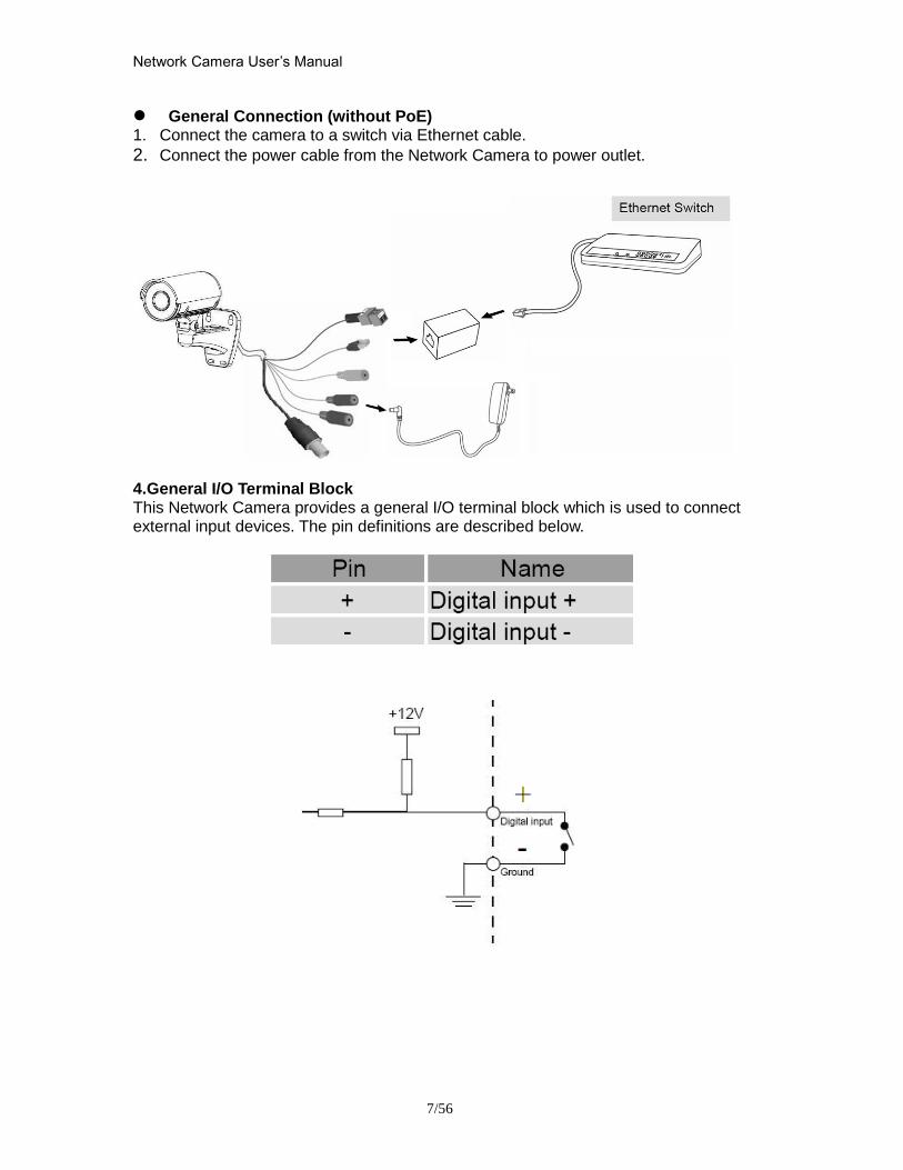
Network Camera Userrsquos Manual
756
General Connection (without PoE) 1 Connect the camera to a switch via Ethernet cable
2 Connect the power cable from the Network Camera to power outlet
4General IO Terminal Block This Network Camera provides a general IO terminal block which is used to connect external input devices The pin definitions are described below
Network Camera Userrsquos Manual
856
Connect to the Network Camera
Install the IP Finder program When you installed your Network camera on your LAN environment you may install ldquoIP Finderrdquo to discover Network camerarsquos IP address The Administrator must place the product software CD into the CD-ROM drive of the PC running in Microsoft Windows An auto-run program will pop up (If the program is not on auto-run go to the root directory of the software CD and click on ldquoautorunexerdquo)
Click on ldquoSoftware Utilityrdquo item after the window contents changed click on ldquoInstall IP Finderrdquo to run ldquoIP Finderrdquo program
Network Camera Userrsquos Manual
956
ldquoIP Finderrdquo is used to search the IP address of Network Cameras or Video servers on a LAN After searching Video Servers or Network Cameras will be located by the IP Finder
Network Camera Userrsquos Manual
1056
Search Camera
Click search Camera button the program will search for all family network devices on the same LAN After searching the main installer window will pop up Click on the MAC and model name which matches the product label on your device to connect to the Network Camera via Internet Explorer
Network Camera Userrsquos Manual
1156
Setup Camera Auto Install Wizard will be started and that it can auto guide through the installation process Press the ldquoNextrdquo button execute next process For more information please refer to the Network section on page 31
Network Camera Userrsquos Manual
1256
Network Camera Userrsquos Manual
1356
Network Camera Userrsquos Manual
1456
Network Camera Userrsquos Manual
1556
Bonjour program Safari browser supports Bonjour search program the will search for all family network devices on the same LAN
Network Camera Userrsquos Manual
1656
C2mylevel1com (Free DDNS service) 1 When you want to connect the network camera over Internet you can use the service ldquoC2mylevel1comrdquo The ldquoip-discoverycomrdquo is a free DDNS server for this camera Make sure that the router must start UPnP and DHCP server functions You can get the domain name which you wish very easily after registration In Network pagemdashDDNS settings of this camera you just input the host name you want and your e-mail address and click ldquoRegisterrdquo then you can have the hostname for this camera not longer than 20 seconds if the DDNS registration result is OK Then you can connect to this ip camera by httpXXXc2mylevel1com XXX the host name you type The HTTP port (get it automatically by c2mylevel1 server)
User password Default the password is last six number of the MAC To change ldquorootrdquo password at ldquoSecurity configurationrdquo can change the user password This ldquoUser passwordrdquo is entered in the c2mylevel1com Password Note You must set the ports between your router and camera manually if the registration is failed
Network Camera Userrsquos Manual
1756
Initial Access to the Network Camera
(1) For the initial access to the Network Camera in Windows the web browser may prompt for permission to install a new plug-in for the Network Camera This plug-in has been registered for certificate and is used to display the video in the browser
Users may click on to proceed
1 Click ldquoInstallrdquo and ldquoRunrdquo ActiveX controls 2 The video will be displayed
Network Camera Userrsquos Manual
1856
Primary userrsquos capability
Main Screen with Camera View The main page has three parts
1 Configuration functions The camera can be configured using these user interfaces
2 Connection control buttons These buttons provide the remote and local switching stream
3 Camera View What the camera sees Click the configuration in the bottom of left column to link to the configuration page
Configuration functions ldquoClient Settingsrdquo Clicking on this button links you to the client setting pages please check the following session for more details
ldquoConfigurationrdquo Please notes that only the administrator can access it ldquo Languagerdquo Click this button to choose a language for the user interface Language options are available in English traditional Chinese Simplified Chinese Japanese Spanish Portuguese French German Italiano
1
2
3
Network Camera Userrsquos Manual
1956
Camera view On the top of image shows the connecting type of the Network Camera and the current datetime
View capabilities
1 Click this button to capture and save still images The captured images will be
displayed in pop-up window Right-click the image and choose Save Picture As to save it in JPEG format
2 The button selection lets you open a digital zoom and to control the window to
enlarge a specified area in the camera view
3 Click this button to switch to full screen mode Press the ldquoEscrdquo key to switch back to normal mode
4 Click on this button freeze the video and playing when you click again
5 Click on this button stop video output
6 Use this functionyou can record video in your PC by browser directly The files
format will be in MP4
7 Click on this button adjust the audio volume amp Latency
8 Click on this button switch Mute OnOff
9 Click on this button to adjust the Function ldquo2-way audiordquo to be EnableDisable Enable this function request insert an external speaker The server can play sound from the client and receive sound from the environment and send to client
10 Click on this button to adjust the Microphone volume
Network Camera Userrsquos Manual
2056
11 Click on this button switch Microphone Mute OnOff Connection control buttons
1 ldquoConnectionrdquo User can choose Remote or Local mode for best connection quality Proposal Internet environment switch Remote mode
2 ldquoVideo Streamrdquo User can choose stream1 or stream2
Network Camera Userrsquos Manual
2156
Client Setting
1 ldquoIntranet Protocol Optionsrdquo Setting camera in intranet mode of protocol ldquoUDPrdquo Select use UDP protocol connect camera ldquoTCPrdquo Select use TCP protocol connect camera ldquoHTTPrdquo Select use HTTP protocol connect camera
2 ldquoInternet Protocol Optionsrdquo Setting camera in internet mode of protocol ldquoUDPrdquo Select use UDP protocol connect camera ldquoTCPrdquo Select use TCP protocol connect camera ldquoHTTPrdquo Select use HTTP protocol connect camera
3 ldquoRecording optionsrdquo Users can record live video as they are watching by
clicking start MP4 Recording on the main page Here you can specify the storage destination and file name
ldquoFolderrdquo Specify the storage destination for the recorded video files ldquoFile name prefixrdquo Enter the text that will be appended to the front of the video
file name ldquoAdd date and time suffix to file namerdquo Select this option to append the date
and time to the end of the file name
Network Camera Userrsquos Manual
2256
NOTEProtocol Options which allows choices on connection protocol between client and
server There are three protocols choices to optimize your usage ndash UDP TCP HTTP The UDP protocol allows for more real-time audio and video streams However some packets may be lost due to network burst traffic and images may be obscured The HTTP protocol allows for less packet loss and produces a more accurate video display The downside with this protocol is that the real-time effect is worse than that with the UDP protocol The TCP guarantees the complete delivery of streaming data and thus provides better video quality However the real-time effect is not as good as that of the UDP protocol If no special need is required UDP protocol is recommended Generally speaking the client choice will be in the order of UDP rarr HTTP After the Network Camera is connected successfully ldquoProtocol Optionrdquo will indicate the selected protocol The selected protocol will be recorded in the users PC and will be used for the next connection If the network environment is changed or the user wants to let the web browser to detect again manually select the UDP and TCP protocol save and return HOME to re-connect
Network Camera Userrsquos Manual
2356
Definitions in Configuration
Please note that only the Administrator can access the system configuration Each category in the left column will be explained on the following pages
System parameters
1 ldquoGeneral Settingrdquo
(1) ldquoHost namerdquo The text displays the title on the top of the main page
Firmware version
Network Camera Userrsquos Manual
2456
2 ldquoTime Settingrdquo (1) ldquoTime zonerdquo Choose a time zone from the down arrow
(2) ldquoDaylight savingrdquo For summertime It will be one hour ahead
(3) ldquoCurrent Timerdquo Network camera set the current time
(A) ldquoKeep current date and timerdquo Click on this to keep the current date and time of the Network Camera An internal real-time clock maintains the date and time even when the power of the system is turned off
(B) ldquoSync with computer timerdquo Synchronize the date and time in the Network Camera according to the local computer
(C) ldquoManualrdquo Adjust the date and time by the Administrator
(D) ldquoAdjust by NTP serverrdquo Synchronize the time according NTP server over the Internet whenever the Network Camera is switched on It fails if the assigned time-server cannot be found
(a) ldquoNTP serverrdquo Assign the IP address or domain name of the time-server Leaving the text box blank connects the Network Camera to the default time-servers
(b) ldquoUpdate intervalrdquo Select 0 ~ 23 hours update with the time on the NTP server
3 ldquoDI statusrdquo Please go to Application page for setting the DI
Network Camera Userrsquos Manual
2556
Security
Security setting The administrator account name is ldquorootrdquo which is permanent and can not be deleted If you want to add more accounts in the Manage User column please set a password for the ldquorootrdquo account first 1 ldquoChange root passwordrdquo Change the Administratorrsquos password by typing in the new password identically in both text boxes The typed entries will be displayed as asterisks for security purposes After pressing ldquofinishrdquo the web browser will ask the Administrator for the new password to access
2 ldquoManage privilegerdquo You can modify the manage privilege of operators or viewers Check or uncheck the item then click finish to enable the settings
3 ldquoManage userrdquo (1) ldquoAdd a new userrdquo Administrators can add up to 20 user accounts
(A) Input the new userrsquos name and password (B) Select the privilege level for the new user account Click Finish to enable the
setting
(2) ldquoDelete a userrdquo Select an existing user name Click Finish to enable the setting
Network Camera Userrsquos Manual
2656
(3) ldquoUpdate a existing userrdquo Select an existing user name Administrators can modify userrsquos password and privilege Click Finish to enable the setting
Access rights are sorted by user privilege (Administrator Operator and Viewer) Only administrators can access the Configuration page Operators cannot access the Configuration page but can use the URL Commands to get and set the value of parameters Viewers access only the main page for live viewing
Network
Any changes made on this page will restart the system in order to validate the changes Make sure every field is entered correctly before clicking on ldquofinishrdquo
Network Camera Userrsquos Manual
2756
Network Setting ldquoLANrdquo amp ldquoPPPoErdquo The default type is LAN Select PPPoE if using ADSL
1 LAN
The default status is Get IP address automatically This could be tedious to perform software installation whenever the Network Camera starts Therefore once the network is set especially for the IP address should be entered correctly Select Use fixed IP address then the Network Camera will skip installation The Network Camera will automatically restart and operate normally after a power outage You can run IP installer to check the IP address assigned to the Network Camera if the IP address is forgotten or you can use the UPnP function provided by the Network Camera (MS Windows XP provides UPnP function at My Network Place)
(1) ldquoGet IP address automaticallyrdquo (2) ldquoUse fixed IP addressrdquo
- ldquoIP addressrdquo This is necessary for network identification - ldquoSubnet maskrdquo This is used to determine if the destination is in the same subnet The default value is ldquo2552552550rdquo - ldquoDefault routerrdquo This is a gateway used to forward frames to destinations in a different subnet Invalid router setting will fail the transmission to destinations in different subnet - ldquoPrimary DNSrdquo The primary domain name server that translates hostnames into IP addresses - ldquoSecondary DNSrdquo Secondary domain name server backups the Primary DNS - ldquoEnable UPnP presentation amp port forwardingrdquo Enable UPnP ability - ldquoHttp portrdquo This can be typed besides the default Port 80 Once the port is changed the users must make sure the change for the connection is successful For instance when the Administrator changes the HTTP port of the Network Camera which IP address is 192168020 from 80 or 1025 to 65535 the users must type in the web browser ldquohttp1921680208080rdquo instead of ldquohttp192168020rdquo
- ldquoRTSP Portrdquo RTSP port can be typed besides the default Port 554 - ldquoRTP Portrdquo The RTP port can be typed besides the default Port 54
Note Please set Video RTP port in even number after default value port 54 Then
Video RTCP potAudio RTP portAudio RTCP port will automatically set the
values in ascending
- ldquoRTSP Streaming access namesrdquo The RTSP streaming currently supports video only audio only and audiovideo To use the audiovideo stream type the URL asldquortsp613012543liveNsdprdquo
2 PPPoE If using the PPPoE interface you should fill the following settings from ISP
(1) ldquoUser namerdquo The login name of PPPoE account (2) ldquoPasswordrdquo The password of PPPoE account (3) ldquoConfirm passwordrdquo Input password again for confirmation
Network Camera Userrsquos Manual
2856
DDNS Setting 1 ldquoEnable DDNSrdquo This option turns on the DDNS function
2 ldquoip-discoveryrdquo In the Register column fill in the Host name (xxxx ip-discovery) Email Key and Confirm Key then click Register After a host name has been successfully created a success message will be displayed in the DDNS Registration Result column and messaging E-mail
3 ldquo3rd party DDNSrdquo This is enable or disable 3rd party DDNS 4 ldquoProviderrdquo The provider list contains hosts that provide DDNS services Please connect to the service providerrsquos website to make sure the service charges
5 ldquoHost Namerdquo If the User wants to use DDNS service this field must be filled Please input the hostname that is registered in the DDNS server
6 ldquoUser namerdquo The Username or E-mail field is necessary for logging in the DDNS server or notify the User of the new IP address Note when this field is input as ldquoUser namerdquo the following field must be input as ldquoPasswordrdquo
7 ldquoPasswordrdquo Please input the password or key to get the DDNS service
8 ldquofinishrdquo Click on this button to save modify settings for the DDNS service
Network Camera Userrsquos Manual
2956
Access list
Access list setting 1 How to control access permission by verifying the client PCrsquos IP
address General Settings General Settings
Add a rule to configure an AllowedDenied list Click Add to add a rule
Network Camera Userrsquos Manual
3056
to AllowedDenied list There are three types of rules for user to set up ldquoSinglerdquo This rule allows the user to add an IP address to the AllowedDenied list For example
ldquoNetworkrdquo This rule allows the user to assign a network address and corresponding subnet mask to the AllowDeny List The IP address is written in the CIDR format For example
Network Camera Userrsquos Manual
3156
ldquoRangerdquo This rule allows the user to assign a range of IP addresses to the AllowDeny List This rule is only applied to IPv4 For example
Network Camera Userrsquos Manual
3256
Audio and Video setting
Network Camera Userrsquos Manual
3356
General Setting 1 ldquoColor moderdquo Select use color or monochrome video display
2 ldquoVideo orientationrdquo The orientation of video
(1) ldquoFliprdquo Vertically rotate the video
(2) ldquoMirrorrdquo Horizontally rotates the video
3 ldquoEnvironmentrdquo The orientation of video
(1) ldquoindoorrdquo This option is usually selected when the Network Camera is placed in indoor environments
(2) ldquooutdoorrdquo This option is usually selected when the Network Camera is placed in outdoor environments
4 ldquoPower freqrdquo Select 50 Hz or 60Hz power line frequency
The fluorescent light will flash according to the power line frequency that
depends on local utility Change the frequency setting to eliminate uncomfortable flash image when the light source is only fluorescent light
Video Setting 1 ldquoContrastrdquo Adjust the image contrast level which ranges from -5 to +5 The default value is set to 0
2 ldquoBrightnessrdquo Adjust the image brightness level which ranges from -5 to +5 The default value is set to 0
3 ldquoSaturationrdquo Adjust the image saturation level which ranges from -5 to +5 The default value is set to 0
4 ldquoSharpnessrdquo Adjust the image sharpness level which ranges from -5 to +5 The default value is set to 0
5 ldquoEVrdquo Exposure value represent the expected target value of the luminance of
the weighting result of AE windows in the image and its tolerance as offset
6 ldquoGainrdquo In the slide bar of Gain there are also two sliders which represent the
limitations to control the maximum gain value and the minimum one respectively Normally the minimum value is to 1x for better quality
Network Camera Userrsquos Manual
3456
Exposure setting Here it provides 3 mode Auto Backlight and Customized Auto and
Backlight modes are 2 default settings for general purpose and backlight scene
respectively
Customized mode relates to the grid window above can be pointed on for
interesting areas Within the mode Customized 1615 grids windows can be chosen to match wherewhat you are interested in Push down left-button of mouse and drag to draw the grids for interesting areas or push down right-button of mouse and drag to clean the grids for insignificant areas
ldquoTarget Luminance and Offsetrdquo
These two slide bar Target Luminance and Offset represent the expected
target value of the luminance of the weighting result of AE windows in the image and its tolerance as offset For example target luminance is set to 100 and target offset is set to 20 that means the average luminance of the AE window should be in the range from 80 to 120 (100plusmn(10 When the actual luminance does not meet this range the AE function will adjust shutter and gain to meet it as possible In some extreme cases it cannot reach the target because the environment is too bright or dark When the environment is not consistent eg with big moving objects and the offset is too narrow the AE will act more frequently that will cause the background of view inconsistent The offset value is recommended to set 15~25 of target luminance
Network Camera Userrsquos Manual
3556
ldquoGainrdquo
In the slide bar of Gain there are also two sliders which represent the limitations
to control the maximum gain value and the minimum one respectively Normally the minimum value is to 1x for better quality It is not allowed if the maximum slider and the minimum one are set to the same value without adjustable interval Besides the noise will be increased if the actual gain is too large When the max slider is dragged over sensors max gain the slide bar will become deep blue to represent it will apply Mozart 3s digital gain which extend the max gain for very low light
ldquoShutter Speedrdquo
There are 2 fields minimal and maximal time for the range of Shutter Speed
The precision of the parameter is 11000000 sec but it is NOT actual precision of the shutter speed of the sensor The actual precision of the shutter speed depends on each sensorrsquos specification Here it will be rounded to approach sensorrsquos effective exposure time To avoid flickering or banding phenomenon under fluorescent light the actual shutter speed will be locked at 1120 160
130 if Power Line Frequency is 60Hz or 1100 150 125 if Power Line
Frequency is 50Hz The setting of Power Line Frequency is on the sub-tab Video
and Audio The exposure may not be stable if the maximum value and the minimum one are set to the same value without adjustable interval Besides the frame rate will drop down if the actual shutter speed is too slow to meet expected frame rate
Noise reduction
Provides 2D and 3D features
Wide Dynamic Range Enable Wide Dynamic Range auto in different level to improve the exposure when both bright and dark areas simultaneously in the field of view of the camera The default is off
Infrared Led Setting 1 ldquoInfrared LED Controlrdquo IR led for Day and Night (Option) User can turn onoff the built-in IR led This function is very useful under low illumination environment
(1) ldquoAutordquo Select IR sensitivity from 0 to 4
(2) ldquoManualrdquo Turn onoff the IR led manually
- ldquoTurn onrdquo Turn on led - ldquoTurn offrdquo Turn off led
2 ldquoLow lux moderdquo The video quality will be improved when the camera is in low lux environment (1) ldquoDisable dark moderdquo Disable low lux mode
(2) ldquoEnable dark moderdquo Enable low lux mode
Network Camera Userrsquos Manual
3656
Video output Setting 1 ldquovideo outputrdquo Can switch between NTSC and PAL
Audio Setting 1 ldquoMuterdquo Audio mute
2 ldquoMicrophone rdquo External microphone
3 ldquoMic Volumerdquo Adjust microphone volume which ranges from 1 to 46
Video record
Schedule mode
(1) ldquoEvery dayrdquo EnableDisable every day application
(2) ldquoWeek dayrdquo EnableDisable week day application
(3)ldquoSelected dayrdquo EnableDisable selected day application
Schedule information
(1) Enter the ldquoStart timerdquo and ldquoStop timerdquo for day mode Note that the time format is [hhmm] and is expressed in 24-hour clock time By default the start and end time of day mode are set to 010000 and 235959
Network Camera Userrsquos Manual
3756
(2)ldquoSunrdquoldquoMonrdquoldquoTuerdquoldquoWedrdquoldquoThurdquoldquoFrirdquoldquoSatrdquo Select the days of the week to perform the application
(3) ldquoStart dayrdquo and ldquoStart timerdquo as the start timing the time ldquoEnd dayrdquo and ldquoEnd timerdquo as the end timing the time
(4) ldquoEnable cyclic recordingrdquo The cyclic recording function is enabled during the transaction stage when a storage space is full and the incoming streaming data is about to overwrite the previously saved videos
Record parameters (1)Source Select a stream for the recording source
(2)Recording interval Select the recording time interval
(3)Prefix file name You can setting the file name and enable or disable to add the date and time on file name
Response mode There are two choices of server types available NAS SD Card Select the item to display the detailed configuration options
(1)rdquoNASrdquo
--ldquoNAS server addressrdquo Enter IP address of the NAS server
--ldquoNAS shared directoryrdquo Enter the NAS shared directory path --ldquoWorkgrouprdquo Enter the NAS workgroup parameter --ldquoUser accountrdquo Enter the login name of the NAS account --ldquoUser passwordrdquo Enter the password of the NAS account Note Video record with the Application must be set to the same shared directory
path If you would like do detail recording settings or multi-channel recording please install bundled 64CH recording software in CD
Network Camera Userrsquos Manual
3856
Stream
Audio codec setting
(1)ldquoAudio codec typerdquo There are two choices of audio codec types
available rdquoAMRrdquo ldquoAACrdquo and rdquoG711rdquo
(2) ldquoBit raterdquo -- ldquoAMRrdquo The bit rates are selectable at the following rates
47505150590067007400795010200 and 12200
-- ldquoAACrdquo The bit rates are selectable at the following rates 8Kbps16Kbps 24Kbps and 32Kbps
-- ldquoG711rdquo pcmu and pcma
Video codec setting (1) ldquoSelect Streamrdquo The Network Camera supports ldquoStream 1rdquoand ldquoStream 2rdquo
(2) ldquoVideo codecrdquo The Network Camera supports three kind of video compression mode ldquoH264rdquo or ldquoMPEG4rdquo or ldquoMJPEGrdquo User can choose one of
Network Camera Userrsquos Manual
3956
these compression modes based on requirement or application
(3) ldquoVideo sizerdquo Click the down arrow to choose the quality of image (1920x1080 1280x1024 1280x800 640x480 320x240 176x144)
(4) ldquoConnection typerdquo User can select this button to choose the better video amp links quality (Internet mode or Intranet mode)
(5) ldquoFrame raterdquo This limits the maximal refresh frame rate per second Set the frame rate higher for a smoother video quality
(6) ldquoIntra frame periodrdquo Determine how often to plant an ldquoI framerdquo The shorter the duration the more likely you will get a better video quality but at the cost of higher network bandwidth consumption
(7) ldquoVideo Quality typerdquo Setting optimizes bandwidth utilization and video quality
-- ldquoConstant bit raterdquo User can adjust the video quality from 20 Kbps to 12 Mbps
-- ldquoFixed qualityrdquo user can select from lowest quality to get best quality according The ldquoQualityrdquo are selectable at the following rates From 1 to 20
Snapshot and time display setting Adjust the photo size specifications and choose whether to mark time on the video and photo
Network Camera Userrsquos Manual
4056
Application
Schedule mode
(1) ldquoEvery dayrdquo EnableDisable every day application
(2) ldquoWeek dayrdquo EnableDisable week day application
(3) ldquoSelected dayrdquo EnableDisable selected day application
Schedule information (1) Enter the ldquoStart timerdquo and ldquoStop timerdquo for day mode
Note that the time format is [hhmmss] and is expressed in 24-hour clock time By default the start and end time of day mode are set to 010000 and 235959
(2) ldquoSunrdquoldquoMonrdquoldquoTuerdquoldquoWedrdquoldquoThurdquoldquoFrirdquoldquoSatrdquo Select the days of the week to perform the application
(3) ldquoStart dayrdquo and ldquoStart timerdquo as the start timing the time ldquoEnd dayrdquo and ldquoEnd timerdquo as the end timing the time
Trigger mode
(1) ldquoVideo motion detectionrdquo EnableDisable video motion application (2) ldquoPeriodicallyrdquo This option allows the Network Camera to trigger
periodically for every other defined minute
Network Camera Userrsquos Manual
4156
(3) ldquoDigital inputrdquo This option allows the Network Camera to use an external digital input device or sensor as a trigger source Depending on your application there are many choices of digital input devices on the market which helps to detect changes in temperature vibration sound and light etc
parameters
(1) ldquoMotion parametersrdquo Higher sensitivity and small threshold will allow easier motion detection
(2) ldquoPeriod parametersrdquo This option allows the Network Camera to trigger periodically for every other defined seconds Up to 999 seconds are allowed
(3) ldquoDigital input parametersrdquo Select the digital input type and set trigger time
Media mode There are four choices of media types available ldquoSnapshotrdquo ldquoMessagerdquo ldquoRecord(Motion Detection only)rdquo and ldquoSystem logrdquo
Snapshot amp Record file setting You can setting the file name and enable or disable to add the date and time on file name Can setting the digital output duration seconds Response mode There are four choices of server types available Email FTP NAS and SD Card storage Select the item to display the detailed configuration options
(1)ldquoEmailrdquo -- ldquoEmail security moderdquo If your SMTP server requires a secure connection (SSL or TLS) check This server requires a secure connection (SSL or TLS) -- ldquoSender emailrdquo address Enter the email address of the sender -- ldquoRecipient emailrdquo address Enter the email address of the recipient
-- ldquoServer addressrdquo Enter the domain name or IP address of the email server
--ldquoUser namerdquo Enter the user name of the email account if necessary
--ldquoPasswordrdquo Enter the password of the email account if necessary
--ldquoServer portrdquo The default mail server port is set to 25 You can also manually set another port
(2)rdquoFTPrdquo -- ldquoServer addressrdquo Enter the domain name or IP address of the FTP server
-- ldquoServer portrdquo By default the FTP server port is set to 21
-- ldquoUser namerdquo Enter the login name of the FTP account
-- ldquoPasswordrdquo Enter the password of the FTP account
-- ldquoFTP folder namerdquo Enter the folder where the media file will be placed If the folder name does not exist the Network Camera will create one on the FTP server
(3)rdquoHTTP rdquo
-- ldquoURLrdquo Enter the URL of the HTTP server
-- ldquoUser accountrdquo Enter the user name if necessary -- ldquoUser passwordrdquo Enter the password if necessary
(4)rdquoNASrdquo --ldquoNAS server addressrdquo Enter IP address of the NAS server
--ldquoNAS shared directoryrdquo Enter the NAS shared directory path
Network Camera Userrsquos Manual
4256
--ldquoWorkgrouprdquo Enter the NAS workgroup parameter --ldquoUser accountrdquo Enter the login name of the NAS account --ldquoUser passwordrdquo Enter the password of the NAS account Note Video record with the Application must be set to the same shared directory
path If you would like do detail recording settings or multi-channel recording please install bundled 64CH recording software in CD
Network Camera Userrsquos Manual
4356
Storage
Manage the storage device
S torage Status Here show the storage device information
NAS server setting
1
2
3
Network Camera Userrsquos Manual
4456
(1) ldquoNAS Host namerdquo Choose and input the NAS Host name of this camera
(2) ldquoWorkgrouprdquo Input the name of Workgroup You can see the NAS Host name you input in the same workgroup with your PC Then you can connect to this device and download the files easily from SD card which is inserted to this camera
File operation Move the mouse over the file Press the mouse right button that Right-click menu is displayed You can delete files Move the mouse over the directory Press the mouse left button that the file structure expand Press the mouse right button that Right-click menu is displayed You can choose upload or delete files NOTEAllow the user to upload or delete files when the storage device is not write-
protected If the SD card canrsquot be detected please link to the following URL httpwwwsdcardorgconsumersformatter to download the ldquoSD Formatter Kitrdquo formatting your SD card
Network Camera Userrsquos Manual
4556
Syslog
The Network camera supports log the system messages on remote server The protocol is compliant to RFC 3164 If you have external Linux server with sys log service use ldquo-rrdquo option to turn on the facility for receiving log from remote machine Or you can use some software on Windows that is compliant to RFC 3164 An example is Kiwi Syslog Daemon Visit httpwwwkiwisyslogcomkiwi-syslog-daemon-overview Check ldquoSetuprdquo and ldquoEnablerdquo then input the ldquoIP addressrdquo and ldquoportrdquo number of the log server to enable the remote log facility In the ldquoCurrent logrdquo it displays the current system log file The content of the log provides useful information about configuration and connection after system boot- up
ldquofinishrdquo Click on this button to save modify settings
Network Camera Userrsquos Manual
4656
Status and Parameters
User can find a lot of information about the system such as ldquoUpnp port forwardingrdquo
ldquoTraversing NATrdquo ldquoPublic IPrdquo and so on User also can get the number of current viewer of the Network Camera here
Network Camera Userrsquos Manual
4756
Maintenance
1 ldquoReboot systemrdquo The ldquoRebootrdquo button will reboot the Network Camera Itrsquos useful while the Network Camera got problem 2 ldquoRestore systemrdquo Click on ldquoRestorerdquo button on the configuration page to restore the factory default settings Restore all settings to factory default except settings in ldquoNetwork type rdquo and ldquoRoot Passwordrdquo The system will restart and require the installer program to set up the network again
3 ldquoCalibraterdquo Recalibrate the auto focus position to the default range to recover the tolerance caused by some external forces 4 ldquoExportImport filerdquo -- Export setting backup file Click to export all parameters for the device and user-defined scripts
-- Upload setting backup file Click Browsehellip to upload a setting backup file Please note that the model and firmware version of the device should be the same as the setting backup file If you have set up a fixed IP or other special settings for your device it is not suggested to upload a settings backup file
4 ldquoUpgrade firmwarerdquo Select the firmware file and click upgrade button Please be aware that you should not turn off the power during updating the firmware and wait for finish message
Network Camera Userrsquos Manual
4856
Warning The upgrade firmware procedure cannot be interrupted If the power
andor network connection are broken during the procedure it might possibly cause serious damage to the Network Camera
Note When upgrade firmware please wait for 120~210 seconds and then you can connect to Network Camera again The system will restart and require the installer program to set up the network again
Network Camera Userrsquos Manual
4956
Appendix
A Troubleshooting amp Frequently Asked Questions Q1 Status led does not light up
A1 First make sure that「ConfigurationgtSystemgtTurn off the LED indicator」is disabled
If it is check the item and the led should light up Second if red led does not light up please check that the power adapter in the package is plugged correctly And last if green led does not light up please check that category 5 UTP cable is plugged correctly If the problem is still not solved please contact your dealer for further help
Q2 What kind of Ethernet cable is used by network camera
A2 The network Camera uses Category 5 UTP cable allowing 10 andor 100 Base-T networking
Q3 The Network Camera will be installed and work if a firewall exists on
the network
A3 There are two way to set up the IP camera at Internet (1) By UPnP Port Forwarding 1 Select an IP router It must support UPnP port forwarding and enable this function
first
2 Connect camera RJ45 cable to IP router and the router is also connected to Internet
3 Plug power cord to camera
4 Go to camera Network page Enable UPnP port forwarding
5 Check camera status we can see the ports had been successfully opened
Network Camera Userrsquos Manual
5056
6Type IP address8080 at browser Then you can see camera through Internet
7You can also type the ddns name at below label of camera on browser URL field For example you may type ah00001ip-discoverycom8080 (2) By Setting Port Forwarding Manually 1 Select a router Set the port forwarding as following
Network Camera Userrsquos Manual
5156
PS Port 80 is HTTP Port port 53 is stream port port 554 is RTSP port and port 443 is HTTPS port 2Go to camera Network page Disable UPnP port forwarding function
Network Camera Userrsquos Manual
5256
3 Type IP address at browser Then you can see camera through Internet
4 You can also type the ddns name at below label of camera on browser URL field For example you may type ah00001ip-discoverycom
Note The firewall software at PC may block the transfer of network camera Please remove or stop the kind software
Q4 How can I find the network camera in the local area network
A4 By using the IP Finder2 program or using UPnP to find it
Q5 IP Finder2 program cannot find Network Camera in the local area
network at first time
A5 Make sure the subnet of network camera is same as your PC If the local area network supports DHCP the camera is ldquoGet IP address automaticallyrdquo in the ldquoNetworkrdquo page default If the local area network does not support DHCP change your PC IP address to ldquo1921680xxxrdquo
Network Camera Userrsquos Manual
5356
Q6 How can I restore the network camera to default value
A6 Use a gem clip to press on the inside button Network camera begins to restore default value You can also press the button ldquoFactoryrdquo in ldquoMaintenancerdquo page to restore the default value
Q7 I cannot play the recorded video file
A7 Install the audio codec in the CD and use the Windows Media Player 10 or later to play the ASF or AVI file recorded by the network camera
Q8 Infrared led does not light up
A8 Check「ConfigurationgtAudio and VideogtInfrared LED Control」 is ldquoAutordquo or
ldquoManual》Turn onrdquo
Q9 The network camera cannot focus accurately
A9 (1) The lens is dirty or dust is attached Clean the lens with lens cleaner And then adjust the camera focus manually (2) The image may be out of focus If the object is too near move the object away from Network Camera
Q10 The cover of network camera is warm Is it normal
A10 Network camera is a precision device The internal material has the operational temperature and it is normal when user touch the cover feels warm It is recommended to put the network camera at aired place and not put at any other device
Q11 The process of upgrade firmware abort
A11 Contact your dealer for further help
Q12 Cannot access the login page and other web pages of Network
Network Camera Userrsquos Manual
5456
Camera from Internet Explorer
A12 bull May be due to the network cable Try correcting your network cable and configuration Test the network interface by connecting a local computer to the Network Camera via a crossover cable bull Make sure the Internet connection and setting is ok bull Make sure enter the IP address of Internet Explorer is correct If Network Camera has a dynamic address it may have changed since you last checked it bull Network congestion may prevent the web page appearing quickly Wait for a while The IP address and Subnet Mask of the PC and Network Camera must be in the same class of the private IP address on the LAN bull Make sure the http port used by the Network Camera default=80 is forward to the Network Camerarsquos private IP address bull The port number assigned in your Network Camera might not be available via Internet Check your ISP for available port bull The proxy server may prevent you from connecting directly to Network Camera set up not to use the proxy server bull Confirm that Default Gateway address is correct bull The router needs Port Forwarding feature Refer to your routers manual for details bull Packet Filtering of the router may prohibit access from an external network Refer to your routers manual for details bull Access Network Camera from the Internet with the global IP address of the router and port number of Network Camera bull Some routers reject the global IP address to access Network Camera on the same LAN Access with the private IP address and correct port number of Network Camera bull When you use DDNS you need to set Default Gateway and DNS server address bull If itrsquos not working after above procedure reset Network Camera to default setting and installed it again bull Maybe the IP Address of the Network Camera is already being used by another device or computer bull If the problem is not solved the Network Camera might be faulty Contact your dealer for further help
Network Camera Userrsquos Manual
5556
B Technical specifications
- System RAM 4G bit DDRⅢ
ROM 16MB Flash ROM
- Camera specification 127 inch color CMOS sensor Resolution 1920x1080 10LuxF20 AGC AWB AEC
- Infrared Led High power IR Leds 25~30 M visible AutoManual mode
- Lens 3X optical zoom lens auto iris auto focus f = 28~ 12mm F18 Fov(D) 136deg ~ 39deg
- Protocol TCPIP HTTPUDP SMTP FTP DDNS UPnP Telnet NTP PPPoE RTSP RTPRTCPDHCP and DNS
- Video Resolution Up to 30 frames at 176x144 Up to 30 frames at 320x240 Up to 30 frames at 640x480 Up to 30 frames at 1280x800 Up to 30 frames at 1280x1024 Up to 30 frames at 1920x1080
- Algorithm supported H264MPEG4MJPEG dual codec for streaming video JPEG for still image
- Audio AMRAACG711 External MIC input 2-way audio
- Physical 10 baseT100 baseT and 1000 baseT Fast
Ethernet auto negotiation
- Power Input 100-240VAC 5060Hz 07A Output 12VDC 15A Consumption Max 12 W Support 8023af compliant Power over Ethernet
- EMI amp Safety CE FCC
- Dimension Length 165mm Diameter 75mm
- Operating Environment Temperature -20 ~ 50
Humidity 85 RH
- Weight NET 600g With bracket 800g
Network Camera Userrsquos Manual
5656
Notification of Compliance Appendix C
Europe - EU Declaration of Conformity
For complete DoC please visit httpgloballevel1comdownloadsphpaction=init
GPL License Agreement GPL may be included in this product to view the GPL license agreement goes to httpdownloadlevel1comlevel1gplGPLpdf For GNU General Public License (GPL) related information please visit httpgloballevel1comdownloadsphpaction=init
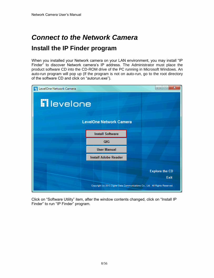
Network Camera Userrsquos Manual
856
Connect to the Network Camera
Install the IP Finder program When you installed your Network camera on your LAN environment you may install ldquoIP Finderrdquo to discover Network camerarsquos IP address The Administrator must place the product software CD into the CD-ROM drive of the PC running in Microsoft Windows An auto-run program will pop up (If the program is not on auto-run go to the root directory of the software CD and click on ldquoautorunexerdquo)
Click on ldquoSoftware Utilityrdquo item after the window contents changed click on ldquoInstall IP Finderrdquo to run ldquoIP Finderrdquo program
Network Camera Userrsquos Manual
956
ldquoIP Finderrdquo is used to search the IP address of Network Cameras or Video servers on a LAN After searching Video Servers or Network Cameras will be located by the IP Finder
Network Camera Userrsquos Manual
1056
Search Camera
Click search Camera button the program will search for all family network devices on the same LAN After searching the main installer window will pop up Click on the MAC and model name which matches the product label on your device to connect to the Network Camera via Internet Explorer
Network Camera Userrsquos Manual
1156
Setup Camera Auto Install Wizard will be started and that it can auto guide through the installation process Press the ldquoNextrdquo button execute next process For more information please refer to the Network section on page 31
Network Camera Userrsquos Manual
1256
Network Camera Userrsquos Manual
1356
Network Camera Userrsquos Manual
1456
Network Camera Userrsquos Manual
1556
Bonjour program Safari browser supports Bonjour search program the will search for all family network devices on the same LAN
Network Camera Userrsquos Manual
1656
C2mylevel1com (Free DDNS service) 1 When you want to connect the network camera over Internet you can use the service ldquoC2mylevel1comrdquo The ldquoip-discoverycomrdquo is a free DDNS server for this camera Make sure that the router must start UPnP and DHCP server functions You can get the domain name which you wish very easily after registration In Network pagemdashDDNS settings of this camera you just input the host name you want and your e-mail address and click ldquoRegisterrdquo then you can have the hostname for this camera not longer than 20 seconds if the DDNS registration result is OK Then you can connect to this ip camera by httpXXXc2mylevel1com XXX the host name you type The HTTP port (get it automatically by c2mylevel1 server)
User password Default the password is last six number of the MAC To change ldquorootrdquo password at ldquoSecurity configurationrdquo can change the user password This ldquoUser passwordrdquo is entered in the c2mylevel1com Password Note You must set the ports between your router and camera manually if the registration is failed
Network Camera Userrsquos Manual
1756
Initial Access to the Network Camera
(1) For the initial access to the Network Camera in Windows the web browser may prompt for permission to install a new plug-in for the Network Camera This plug-in has been registered for certificate and is used to display the video in the browser
Users may click on to proceed
1 Click ldquoInstallrdquo and ldquoRunrdquo ActiveX controls 2 The video will be displayed
Network Camera Userrsquos Manual
1856
Primary userrsquos capability
Main Screen with Camera View The main page has three parts
1 Configuration functions The camera can be configured using these user interfaces
2 Connection control buttons These buttons provide the remote and local switching stream
3 Camera View What the camera sees Click the configuration in the bottom of left column to link to the configuration page
Configuration functions ldquoClient Settingsrdquo Clicking on this button links you to the client setting pages please check the following session for more details
ldquoConfigurationrdquo Please notes that only the administrator can access it ldquo Languagerdquo Click this button to choose a language for the user interface Language options are available in English traditional Chinese Simplified Chinese Japanese Spanish Portuguese French German Italiano
1
2
3
Network Camera Userrsquos Manual
1956
Camera view On the top of image shows the connecting type of the Network Camera and the current datetime
View capabilities
1 Click this button to capture and save still images The captured images will be
displayed in pop-up window Right-click the image and choose Save Picture As to save it in JPEG format
2 The button selection lets you open a digital zoom and to control the window to
enlarge a specified area in the camera view
3 Click this button to switch to full screen mode Press the ldquoEscrdquo key to switch back to normal mode
4 Click on this button freeze the video and playing when you click again
5 Click on this button stop video output
6 Use this functionyou can record video in your PC by browser directly The files
format will be in MP4
7 Click on this button adjust the audio volume amp Latency
8 Click on this button switch Mute OnOff
9 Click on this button to adjust the Function ldquo2-way audiordquo to be EnableDisable Enable this function request insert an external speaker The server can play sound from the client and receive sound from the environment and send to client
10 Click on this button to adjust the Microphone volume
Network Camera Userrsquos Manual
2056
11 Click on this button switch Microphone Mute OnOff Connection control buttons
1 ldquoConnectionrdquo User can choose Remote or Local mode for best connection quality Proposal Internet environment switch Remote mode
2 ldquoVideo Streamrdquo User can choose stream1 or stream2
Network Camera Userrsquos Manual
2156
Client Setting
1 ldquoIntranet Protocol Optionsrdquo Setting camera in intranet mode of protocol ldquoUDPrdquo Select use UDP protocol connect camera ldquoTCPrdquo Select use TCP protocol connect camera ldquoHTTPrdquo Select use HTTP protocol connect camera
2 ldquoInternet Protocol Optionsrdquo Setting camera in internet mode of protocol ldquoUDPrdquo Select use UDP protocol connect camera ldquoTCPrdquo Select use TCP protocol connect camera ldquoHTTPrdquo Select use HTTP protocol connect camera
3 ldquoRecording optionsrdquo Users can record live video as they are watching by
clicking start MP4 Recording on the main page Here you can specify the storage destination and file name
ldquoFolderrdquo Specify the storage destination for the recorded video files ldquoFile name prefixrdquo Enter the text that will be appended to the front of the video
file name ldquoAdd date and time suffix to file namerdquo Select this option to append the date
and time to the end of the file name
Network Camera Userrsquos Manual
2256
NOTEProtocol Options which allows choices on connection protocol between client and
server There are three protocols choices to optimize your usage ndash UDP TCP HTTP The UDP protocol allows for more real-time audio and video streams However some packets may be lost due to network burst traffic and images may be obscured The HTTP protocol allows for less packet loss and produces a more accurate video display The downside with this protocol is that the real-time effect is worse than that with the UDP protocol The TCP guarantees the complete delivery of streaming data and thus provides better video quality However the real-time effect is not as good as that of the UDP protocol If no special need is required UDP protocol is recommended Generally speaking the client choice will be in the order of UDP rarr HTTP After the Network Camera is connected successfully ldquoProtocol Optionrdquo will indicate the selected protocol The selected protocol will be recorded in the users PC and will be used for the next connection If the network environment is changed or the user wants to let the web browser to detect again manually select the UDP and TCP protocol save and return HOME to re-connect
Network Camera Userrsquos Manual
2356
Definitions in Configuration
Please note that only the Administrator can access the system configuration Each category in the left column will be explained on the following pages
System parameters
1 ldquoGeneral Settingrdquo
(1) ldquoHost namerdquo The text displays the title on the top of the main page
Firmware version
Network Camera Userrsquos Manual
2456
2 ldquoTime Settingrdquo (1) ldquoTime zonerdquo Choose a time zone from the down arrow
(2) ldquoDaylight savingrdquo For summertime It will be one hour ahead
(3) ldquoCurrent Timerdquo Network camera set the current time
(A) ldquoKeep current date and timerdquo Click on this to keep the current date and time of the Network Camera An internal real-time clock maintains the date and time even when the power of the system is turned off
(B) ldquoSync with computer timerdquo Synchronize the date and time in the Network Camera according to the local computer
(C) ldquoManualrdquo Adjust the date and time by the Administrator
(D) ldquoAdjust by NTP serverrdquo Synchronize the time according NTP server over the Internet whenever the Network Camera is switched on It fails if the assigned time-server cannot be found
(a) ldquoNTP serverrdquo Assign the IP address or domain name of the time-server Leaving the text box blank connects the Network Camera to the default time-servers
(b) ldquoUpdate intervalrdquo Select 0 ~ 23 hours update with the time on the NTP server
3 ldquoDI statusrdquo Please go to Application page for setting the DI
Network Camera Userrsquos Manual
2556
Security
Security setting The administrator account name is ldquorootrdquo which is permanent and can not be deleted If you want to add more accounts in the Manage User column please set a password for the ldquorootrdquo account first 1 ldquoChange root passwordrdquo Change the Administratorrsquos password by typing in the new password identically in both text boxes The typed entries will be displayed as asterisks for security purposes After pressing ldquofinishrdquo the web browser will ask the Administrator for the new password to access
2 ldquoManage privilegerdquo You can modify the manage privilege of operators or viewers Check or uncheck the item then click finish to enable the settings
3 ldquoManage userrdquo (1) ldquoAdd a new userrdquo Administrators can add up to 20 user accounts
(A) Input the new userrsquos name and password (B) Select the privilege level for the new user account Click Finish to enable the
setting
(2) ldquoDelete a userrdquo Select an existing user name Click Finish to enable the setting
Network Camera Userrsquos Manual
2656
(3) ldquoUpdate a existing userrdquo Select an existing user name Administrators can modify userrsquos password and privilege Click Finish to enable the setting
Access rights are sorted by user privilege (Administrator Operator and Viewer) Only administrators can access the Configuration page Operators cannot access the Configuration page but can use the URL Commands to get and set the value of parameters Viewers access only the main page for live viewing
Network
Any changes made on this page will restart the system in order to validate the changes Make sure every field is entered correctly before clicking on ldquofinishrdquo
Network Camera Userrsquos Manual
2756
Network Setting ldquoLANrdquo amp ldquoPPPoErdquo The default type is LAN Select PPPoE if using ADSL
1 LAN
The default status is Get IP address automatically This could be tedious to perform software installation whenever the Network Camera starts Therefore once the network is set especially for the IP address should be entered correctly Select Use fixed IP address then the Network Camera will skip installation The Network Camera will automatically restart and operate normally after a power outage You can run IP installer to check the IP address assigned to the Network Camera if the IP address is forgotten or you can use the UPnP function provided by the Network Camera (MS Windows XP provides UPnP function at My Network Place)
(1) ldquoGet IP address automaticallyrdquo (2) ldquoUse fixed IP addressrdquo
- ldquoIP addressrdquo This is necessary for network identification - ldquoSubnet maskrdquo This is used to determine if the destination is in the same subnet The default value is ldquo2552552550rdquo - ldquoDefault routerrdquo This is a gateway used to forward frames to destinations in a different subnet Invalid router setting will fail the transmission to destinations in different subnet - ldquoPrimary DNSrdquo The primary domain name server that translates hostnames into IP addresses - ldquoSecondary DNSrdquo Secondary domain name server backups the Primary DNS - ldquoEnable UPnP presentation amp port forwardingrdquo Enable UPnP ability - ldquoHttp portrdquo This can be typed besides the default Port 80 Once the port is changed the users must make sure the change for the connection is successful For instance when the Administrator changes the HTTP port of the Network Camera which IP address is 192168020 from 80 or 1025 to 65535 the users must type in the web browser ldquohttp1921680208080rdquo instead of ldquohttp192168020rdquo
- ldquoRTSP Portrdquo RTSP port can be typed besides the default Port 554 - ldquoRTP Portrdquo The RTP port can be typed besides the default Port 54
Note Please set Video RTP port in even number after default value port 54 Then
Video RTCP potAudio RTP portAudio RTCP port will automatically set the
values in ascending
- ldquoRTSP Streaming access namesrdquo The RTSP streaming currently supports video only audio only and audiovideo To use the audiovideo stream type the URL asldquortsp613012543liveNsdprdquo
2 PPPoE If using the PPPoE interface you should fill the following settings from ISP
(1) ldquoUser namerdquo The login name of PPPoE account (2) ldquoPasswordrdquo The password of PPPoE account (3) ldquoConfirm passwordrdquo Input password again for confirmation
Network Camera Userrsquos Manual
2856
DDNS Setting 1 ldquoEnable DDNSrdquo This option turns on the DDNS function
2 ldquoip-discoveryrdquo In the Register column fill in the Host name (xxxx ip-discovery) Email Key and Confirm Key then click Register After a host name has been successfully created a success message will be displayed in the DDNS Registration Result column and messaging E-mail
3 ldquo3rd party DDNSrdquo This is enable or disable 3rd party DDNS 4 ldquoProviderrdquo The provider list contains hosts that provide DDNS services Please connect to the service providerrsquos website to make sure the service charges
5 ldquoHost Namerdquo If the User wants to use DDNS service this field must be filled Please input the hostname that is registered in the DDNS server
6 ldquoUser namerdquo The Username or E-mail field is necessary for logging in the DDNS server or notify the User of the new IP address Note when this field is input as ldquoUser namerdquo the following field must be input as ldquoPasswordrdquo
7 ldquoPasswordrdquo Please input the password or key to get the DDNS service
8 ldquofinishrdquo Click on this button to save modify settings for the DDNS service
Network Camera Userrsquos Manual
2956
Access list
Access list setting 1 How to control access permission by verifying the client PCrsquos IP
address General Settings General Settings
Add a rule to configure an AllowedDenied list Click Add to add a rule
Network Camera Userrsquos Manual
3056
to AllowedDenied list There are three types of rules for user to set up ldquoSinglerdquo This rule allows the user to add an IP address to the AllowedDenied list For example
ldquoNetworkrdquo This rule allows the user to assign a network address and corresponding subnet mask to the AllowDeny List The IP address is written in the CIDR format For example
Network Camera Userrsquos Manual
3156
ldquoRangerdquo This rule allows the user to assign a range of IP addresses to the AllowDeny List This rule is only applied to IPv4 For example
Network Camera Userrsquos Manual
3256
Audio and Video setting
Network Camera Userrsquos Manual
3356
General Setting 1 ldquoColor moderdquo Select use color or monochrome video display
2 ldquoVideo orientationrdquo The orientation of video
(1) ldquoFliprdquo Vertically rotate the video
(2) ldquoMirrorrdquo Horizontally rotates the video
3 ldquoEnvironmentrdquo The orientation of video
(1) ldquoindoorrdquo This option is usually selected when the Network Camera is placed in indoor environments
(2) ldquooutdoorrdquo This option is usually selected when the Network Camera is placed in outdoor environments
4 ldquoPower freqrdquo Select 50 Hz or 60Hz power line frequency
The fluorescent light will flash according to the power line frequency that
depends on local utility Change the frequency setting to eliminate uncomfortable flash image when the light source is only fluorescent light
Video Setting 1 ldquoContrastrdquo Adjust the image contrast level which ranges from -5 to +5 The default value is set to 0
2 ldquoBrightnessrdquo Adjust the image brightness level which ranges from -5 to +5 The default value is set to 0
3 ldquoSaturationrdquo Adjust the image saturation level which ranges from -5 to +5 The default value is set to 0
4 ldquoSharpnessrdquo Adjust the image sharpness level which ranges from -5 to +5 The default value is set to 0
5 ldquoEVrdquo Exposure value represent the expected target value of the luminance of
the weighting result of AE windows in the image and its tolerance as offset
6 ldquoGainrdquo In the slide bar of Gain there are also two sliders which represent the
limitations to control the maximum gain value and the minimum one respectively Normally the minimum value is to 1x for better quality
Network Camera Userrsquos Manual
3456
Exposure setting Here it provides 3 mode Auto Backlight and Customized Auto and
Backlight modes are 2 default settings for general purpose and backlight scene
respectively
Customized mode relates to the grid window above can be pointed on for
interesting areas Within the mode Customized 1615 grids windows can be chosen to match wherewhat you are interested in Push down left-button of mouse and drag to draw the grids for interesting areas or push down right-button of mouse and drag to clean the grids for insignificant areas
ldquoTarget Luminance and Offsetrdquo
These two slide bar Target Luminance and Offset represent the expected
target value of the luminance of the weighting result of AE windows in the image and its tolerance as offset For example target luminance is set to 100 and target offset is set to 20 that means the average luminance of the AE window should be in the range from 80 to 120 (100plusmn(10 When the actual luminance does not meet this range the AE function will adjust shutter and gain to meet it as possible In some extreme cases it cannot reach the target because the environment is too bright or dark When the environment is not consistent eg with big moving objects and the offset is too narrow the AE will act more frequently that will cause the background of view inconsistent The offset value is recommended to set 15~25 of target luminance
Network Camera Userrsquos Manual
3556
ldquoGainrdquo
In the slide bar of Gain there are also two sliders which represent the limitations
to control the maximum gain value and the minimum one respectively Normally the minimum value is to 1x for better quality It is not allowed if the maximum slider and the minimum one are set to the same value without adjustable interval Besides the noise will be increased if the actual gain is too large When the max slider is dragged over sensors max gain the slide bar will become deep blue to represent it will apply Mozart 3s digital gain which extend the max gain for very low light
ldquoShutter Speedrdquo
There are 2 fields minimal and maximal time for the range of Shutter Speed
The precision of the parameter is 11000000 sec but it is NOT actual precision of the shutter speed of the sensor The actual precision of the shutter speed depends on each sensorrsquos specification Here it will be rounded to approach sensorrsquos effective exposure time To avoid flickering or banding phenomenon under fluorescent light the actual shutter speed will be locked at 1120 160
130 if Power Line Frequency is 60Hz or 1100 150 125 if Power Line
Frequency is 50Hz The setting of Power Line Frequency is on the sub-tab Video
and Audio The exposure may not be stable if the maximum value and the minimum one are set to the same value without adjustable interval Besides the frame rate will drop down if the actual shutter speed is too slow to meet expected frame rate
Noise reduction
Provides 2D and 3D features
Wide Dynamic Range Enable Wide Dynamic Range auto in different level to improve the exposure when both bright and dark areas simultaneously in the field of view of the camera The default is off
Infrared Led Setting 1 ldquoInfrared LED Controlrdquo IR led for Day and Night (Option) User can turn onoff the built-in IR led This function is very useful under low illumination environment
(1) ldquoAutordquo Select IR sensitivity from 0 to 4
(2) ldquoManualrdquo Turn onoff the IR led manually
- ldquoTurn onrdquo Turn on led - ldquoTurn offrdquo Turn off led
2 ldquoLow lux moderdquo The video quality will be improved when the camera is in low lux environment (1) ldquoDisable dark moderdquo Disable low lux mode
(2) ldquoEnable dark moderdquo Enable low lux mode
Network Camera Userrsquos Manual
3656
Video output Setting 1 ldquovideo outputrdquo Can switch between NTSC and PAL
Audio Setting 1 ldquoMuterdquo Audio mute
2 ldquoMicrophone rdquo External microphone
3 ldquoMic Volumerdquo Adjust microphone volume which ranges from 1 to 46
Video record
Schedule mode
(1) ldquoEvery dayrdquo EnableDisable every day application
(2) ldquoWeek dayrdquo EnableDisable week day application
(3)ldquoSelected dayrdquo EnableDisable selected day application
Schedule information
(1) Enter the ldquoStart timerdquo and ldquoStop timerdquo for day mode Note that the time format is [hhmm] and is expressed in 24-hour clock time By default the start and end time of day mode are set to 010000 and 235959
Network Camera Userrsquos Manual
3756
(2)ldquoSunrdquoldquoMonrdquoldquoTuerdquoldquoWedrdquoldquoThurdquoldquoFrirdquoldquoSatrdquo Select the days of the week to perform the application
(3) ldquoStart dayrdquo and ldquoStart timerdquo as the start timing the time ldquoEnd dayrdquo and ldquoEnd timerdquo as the end timing the time
(4) ldquoEnable cyclic recordingrdquo The cyclic recording function is enabled during the transaction stage when a storage space is full and the incoming streaming data is about to overwrite the previously saved videos
Record parameters (1)Source Select a stream for the recording source
(2)Recording interval Select the recording time interval
(3)Prefix file name You can setting the file name and enable or disable to add the date and time on file name
Response mode There are two choices of server types available NAS SD Card Select the item to display the detailed configuration options
(1)rdquoNASrdquo
--ldquoNAS server addressrdquo Enter IP address of the NAS server
--ldquoNAS shared directoryrdquo Enter the NAS shared directory path --ldquoWorkgrouprdquo Enter the NAS workgroup parameter --ldquoUser accountrdquo Enter the login name of the NAS account --ldquoUser passwordrdquo Enter the password of the NAS account Note Video record with the Application must be set to the same shared directory
path If you would like do detail recording settings or multi-channel recording please install bundled 64CH recording software in CD
Network Camera Userrsquos Manual
3856
Stream
Audio codec setting
(1)ldquoAudio codec typerdquo There are two choices of audio codec types
available rdquoAMRrdquo ldquoAACrdquo and rdquoG711rdquo
(2) ldquoBit raterdquo -- ldquoAMRrdquo The bit rates are selectable at the following rates
47505150590067007400795010200 and 12200
-- ldquoAACrdquo The bit rates are selectable at the following rates 8Kbps16Kbps 24Kbps and 32Kbps
-- ldquoG711rdquo pcmu and pcma
Video codec setting (1) ldquoSelect Streamrdquo The Network Camera supports ldquoStream 1rdquoand ldquoStream 2rdquo
(2) ldquoVideo codecrdquo The Network Camera supports three kind of video compression mode ldquoH264rdquo or ldquoMPEG4rdquo or ldquoMJPEGrdquo User can choose one of
Network Camera Userrsquos Manual
3956
these compression modes based on requirement or application
(3) ldquoVideo sizerdquo Click the down arrow to choose the quality of image (1920x1080 1280x1024 1280x800 640x480 320x240 176x144)
(4) ldquoConnection typerdquo User can select this button to choose the better video amp links quality (Internet mode or Intranet mode)
(5) ldquoFrame raterdquo This limits the maximal refresh frame rate per second Set the frame rate higher for a smoother video quality
(6) ldquoIntra frame periodrdquo Determine how often to plant an ldquoI framerdquo The shorter the duration the more likely you will get a better video quality but at the cost of higher network bandwidth consumption
(7) ldquoVideo Quality typerdquo Setting optimizes bandwidth utilization and video quality
-- ldquoConstant bit raterdquo User can adjust the video quality from 20 Kbps to 12 Mbps
-- ldquoFixed qualityrdquo user can select from lowest quality to get best quality according The ldquoQualityrdquo are selectable at the following rates From 1 to 20
Snapshot and time display setting Adjust the photo size specifications and choose whether to mark time on the video and photo
Network Camera Userrsquos Manual
4056
Application
Schedule mode
(1) ldquoEvery dayrdquo EnableDisable every day application
(2) ldquoWeek dayrdquo EnableDisable week day application
(3) ldquoSelected dayrdquo EnableDisable selected day application
Schedule information (1) Enter the ldquoStart timerdquo and ldquoStop timerdquo for day mode
Note that the time format is [hhmmss] and is expressed in 24-hour clock time By default the start and end time of day mode are set to 010000 and 235959
(2) ldquoSunrdquoldquoMonrdquoldquoTuerdquoldquoWedrdquoldquoThurdquoldquoFrirdquoldquoSatrdquo Select the days of the week to perform the application
(3) ldquoStart dayrdquo and ldquoStart timerdquo as the start timing the time ldquoEnd dayrdquo and ldquoEnd timerdquo as the end timing the time
Trigger mode
(1) ldquoVideo motion detectionrdquo EnableDisable video motion application (2) ldquoPeriodicallyrdquo This option allows the Network Camera to trigger
periodically for every other defined minute
Network Camera Userrsquos Manual
4156
(3) ldquoDigital inputrdquo This option allows the Network Camera to use an external digital input device or sensor as a trigger source Depending on your application there are many choices of digital input devices on the market which helps to detect changes in temperature vibration sound and light etc
parameters
(1) ldquoMotion parametersrdquo Higher sensitivity and small threshold will allow easier motion detection
(2) ldquoPeriod parametersrdquo This option allows the Network Camera to trigger periodically for every other defined seconds Up to 999 seconds are allowed
(3) ldquoDigital input parametersrdquo Select the digital input type and set trigger time
Media mode There are four choices of media types available ldquoSnapshotrdquo ldquoMessagerdquo ldquoRecord(Motion Detection only)rdquo and ldquoSystem logrdquo
Snapshot amp Record file setting You can setting the file name and enable or disable to add the date and time on file name Can setting the digital output duration seconds Response mode There are four choices of server types available Email FTP NAS and SD Card storage Select the item to display the detailed configuration options
(1)ldquoEmailrdquo -- ldquoEmail security moderdquo If your SMTP server requires a secure connection (SSL or TLS) check This server requires a secure connection (SSL or TLS) -- ldquoSender emailrdquo address Enter the email address of the sender -- ldquoRecipient emailrdquo address Enter the email address of the recipient
-- ldquoServer addressrdquo Enter the domain name or IP address of the email server
--ldquoUser namerdquo Enter the user name of the email account if necessary
--ldquoPasswordrdquo Enter the password of the email account if necessary
--ldquoServer portrdquo The default mail server port is set to 25 You can also manually set another port
(2)rdquoFTPrdquo -- ldquoServer addressrdquo Enter the domain name or IP address of the FTP server
-- ldquoServer portrdquo By default the FTP server port is set to 21
-- ldquoUser namerdquo Enter the login name of the FTP account
-- ldquoPasswordrdquo Enter the password of the FTP account
-- ldquoFTP folder namerdquo Enter the folder where the media file will be placed If the folder name does not exist the Network Camera will create one on the FTP server
(3)rdquoHTTP rdquo
-- ldquoURLrdquo Enter the URL of the HTTP server
-- ldquoUser accountrdquo Enter the user name if necessary -- ldquoUser passwordrdquo Enter the password if necessary
(4)rdquoNASrdquo --ldquoNAS server addressrdquo Enter IP address of the NAS server
--ldquoNAS shared directoryrdquo Enter the NAS shared directory path
Network Camera Userrsquos Manual
4256
--ldquoWorkgrouprdquo Enter the NAS workgroup parameter --ldquoUser accountrdquo Enter the login name of the NAS account --ldquoUser passwordrdquo Enter the password of the NAS account Note Video record with the Application must be set to the same shared directory
path If you would like do detail recording settings or multi-channel recording please install bundled 64CH recording software in CD
Network Camera Userrsquos Manual
4356
Storage
Manage the storage device
S torage Status Here show the storage device information
NAS server setting
1
2
3
Network Camera Userrsquos Manual
4456
(1) ldquoNAS Host namerdquo Choose and input the NAS Host name of this camera
(2) ldquoWorkgrouprdquo Input the name of Workgroup You can see the NAS Host name you input in the same workgroup with your PC Then you can connect to this device and download the files easily from SD card which is inserted to this camera
File operation Move the mouse over the file Press the mouse right button that Right-click menu is displayed You can delete files Move the mouse over the directory Press the mouse left button that the file structure expand Press the mouse right button that Right-click menu is displayed You can choose upload or delete files NOTEAllow the user to upload or delete files when the storage device is not write-
protected If the SD card canrsquot be detected please link to the following URL httpwwwsdcardorgconsumersformatter to download the ldquoSD Formatter Kitrdquo formatting your SD card
Network Camera Userrsquos Manual
4556
Syslog
The Network camera supports log the system messages on remote server The protocol is compliant to RFC 3164 If you have external Linux server with sys log service use ldquo-rrdquo option to turn on the facility for receiving log from remote machine Or you can use some software on Windows that is compliant to RFC 3164 An example is Kiwi Syslog Daemon Visit httpwwwkiwisyslogcomkiwi-syslog-daemon-overview Check ldquoSetuprdquo and ldquoEnablerdquo then input the ldquoIP addressrdquo and ldquoportrdquo number of the log server to enable the remote log facility In the ldquoCurrent logrdquo it displays the current system log file The content of the log provides useful information about configuration and connection after system boot- up
ldquofinishrdquo Click on this button to save modify settings
Network Camera Userrsquos Manual
4656
Status and Parameters
User can find a lot of information about the system such as ldquoUpnp port forwardingrdquo
ldquoTraversing NATrdquo ldquoPublic IPrdquo and so on User also can get the number of current viewer of the Network Camera here
Network Camera Userrsquos Manual
4756
Maintenance
1 ldquoReboot systemrdquo The ldquoRebootrdquo button will reboot the Network Camera Itrsquos useful while the Network Camera got problem 2 ldquoRestore systemrdquo Click on ldquoRestorerdquo button on the configuration page to restore the factory default settings Restore all settings to factory default except settings in ldquoNetwork type rdquo and ldquoRoot Passwordrdquo The system will restart and require the installer program to set up the network again
3 ldquoCalibraterdquo Recalibrate the auto focus position to the default range to recover the tolerance caused by some external forces 4 ldquoExportImport filerdquo -- Export setting backup file Click to export all parameters for the device and user-defined scripts
-- Upload setting backup file Click Browsehellip to upload a setting backup file Please note that the model and firmware version of the device should be the same as the setting backup file If you have set up a fixed IP or other special settings for your device it is not suggested to upload a settings backup file
4 ldquoUpgrade firmwarerdquo Select the firmware file and click upgrade button Please be aware that you should not turn off the power during updating the firmware and wait for finish message
Network Camera Userrsquos Manual
4856
Warning The upgrade firmware procedure cannot be interrupted If the power
andor network connection are broken during the procedure it might possibly cause serious damage to the Network Camera
Note When upgrade firmware please wait for 120~210 seconds and then you can connect to Network Camera again The system will restart and require the installer program to set up the network again
Network Camera Userrsquos Manual
4956
Appendix
A Troubleshooting amp Frequently Asked Questions Q1 Status led does not light up
A1 First make sure that「ConfigurationgtSystemgtTurn off the LED indicator」is disabled
If it is check the item and the led should light up Second if red led does not light up please check that the power adapter in the package is plugged correctly And last if green led does not light up please check that category 5 UTP cable is plugged correctly If the problem is still not solved please contact your dealer for further help
Q2 What kind of Ethernet cable is used by network camera
A2 The network Camera uses Category 5 UTP cable allowing 10 andor 100 Base-T networking
Q3 The Network Camera will be installed and work if a firewall exists on
the network
A3 There are two way to set up the IP camera at Internet (1) By UPnP Port Forwarding 1 Select an IP router It must support UPnP port forwarding and enable this function
first
2 Connect camera RJ45 cable to IP router and the router is also connected to Internet
3 Plug power cord to camera
4 Go to camera Network page Enable UPnP port forwarding
5 Check camera status we can see the ports had been successfully opened
Network Camera Userrsquos Manual
5056
6Type IP address8080 at browser Then you can see camera through Internet
7You can also type the ddns name at below label of camera on browser URL field For example you may type ah00001ip-discoverycom8080 (2) By Setting Port Forwarding Manually 1 Select a router Set the port forwarding as following
Network Camera Userrsquos Manual
5156
PS Port 80 is HTTP Port port 53 is stream port port 554 is RTSP port and port 443 is HTTPS port 2Go to camera Network page Disable UPnP port forwarding function
Network Camera Userrsquos Manual
5256
3 Type IP address at browser Then you can see camera through Internet
4 You can also type the ddns name at below label of camera on browser URL field For example you may type ah00001ip-discoverycom
Note The firewall software at PC may block the transfer of network camera Please remove or stop the kind software
Q4 How can I find the network camera in the local area network
A4 By using the IP Finder2 program or using UPnP to find it
Q5 IP Finder2 program cannot find Network Camera in the local area
network at first time
A5 Make sure the subnet of network camera is same as your PC If the local area network supports DHCP the camera is ldquoGet IP address automaticallyrdquo in the ldquoNetworkrdquo page default If the local area network does not support DHCP change your PC IP address to ldquo1921680xxxrdquo
Network Camera Userrsquos Manual
5356
Q6 How can I restore the network camera to default value
A6 Use a gem clip to press on the inside button Network camera begins to restore default value You can also press the button ldquoFactoryrdquo in ldquoMaintenancerdquo page to restore the default value
Q7 I cannot play the recorded video file
A7 Install the audio codec in the CD and use the Windows Media Player 10 or later to play the ASF or AVI file recorded by the network camera
Q8 Infrared led does not light up
A8 Check「ConfigurationgtAudio and VideogtInfrared LED Control」 is ldquoAutordquo or
ldquoManual》Turn onrdquo
Q9 The network camera cannot focus accurately
A9 (1) The lens is dirty or dust is attached Clean the lens with lens cleaner And then adjust the camera focus manually (2) The image may be out of focus If the object is too near move the object away from Network Camera
Q10 The cover of network camera is warm Is it normal
A10 Network camera is a precision device The internal material has the operational temperature and it is normal when user touch the cover feels warm It is recommended to put the network camera at aired place and not put at any other device
Q11 The process of upgrade firmware abort
A11 Contact your dealer for further help
Q12 Cannot access the login page and other web pages of Network
Network Camera Userrsquos Manual
5456
Camera from Internet Explorer
A12 bull May be due to the network cable Try correcting your network cable and configuration Test the network interface by connecting a local computer to the Network Camera via a crossover cable bull Make sure the Internet connection and setting is ok bull Make sure enter the IP address of Internet Explorer is correct If Network Camera has a dynamic address it may have changed since you last checked it bull Network congestion may prevent the web page appearing quickly Wait for a while The IP address and Subnet Mask of the PC and Network Camera must be in the same class of the private IP address on the LAN bull Make sure the http port used by the Network Camera default=80 is forward to the Network Camerarsquos private IP address bull The port number assigned in your Network Camera might not be available via Internet Check your ISP for available port bull The proxy server may prevent you from connecting directly to Network Camera set up not to use the proxy server bull Confirm that Default Gateway address is correct bull The router needs Port Forwarding feature Refer to your routers manual for details bull Packet Filtering of the router may prohibit access from an external network Refer to your routers manual for details bull Access Network Camera from the Internet with the global IP address of the router and port number of Network Camera bull Some routers reject the global IP address to access Network Camera on the same LAN Access with the private IP address and correct port number of Network Camera bull When you use DDNS you need to set Default Gateway and DNS server address bull If itrsquos not working after above procedure reset Network Camera to default setting and installed it again bull Maybe the IP Address of the Network Camera is already being used by another device or computer bull If the problem is not solved the Network Camera might be faulty Contact your dealer for further help
Network Camera Userrsquos Manual
5556
B Technical specifications
- System RAM 4G bit DDRⅢ
ROM 16MB Flash ROM
- Camera specification 127 inch color CMOS sensor Resolution 1920x1080 10LuxF20 AGC AWB AEC
- Infrared Led High power IR Leds 25~30 M visible AutoManual mode
- Lens 3X optical zoom lens auto iris auto focus f = 28~ 12mm F18 Fov(D) 136deg ~ 39deg
- Protocol TCPIP HTTPUDP SMTP FTP DDNS UPnP Telnet NTP PPPoE RTSP RTPRTCPDHCP and DNS
- Video Resolution Up to 30 frames at 176x144 Up to 30 frames at 320x240 Up to 30 frames at 640x480 Up to 30 frames at 1280x800 Up to 30 frames at 1280x1024 Up to 30 frames at 1920x1080
- Algorithm supported H264MPEG4MJPEG dual codec for streaming video JPEG for still image
- Audio AMRAACG711 External MIC input 2-way audio
- Physical 10 baseT100 baseT and 1000 baseT Fast
Ethernet auto negotiation
- Power Input 100-240VAC 5060Hz 07A Output 12VDC 15A Consumption Max 12 W Support 8023af compliant Power over Ethernet
- EMI amp Safety CE FCC
- Dimension Length 165mm Diameter 75mm
- Operating Environment Temperature -20 ~ 50
Humidity 85 RH
- Weight NET 600g With bracket 800g
Network Camera Userrsquos Manual
5656
Notification of Compliance Appendix C
Europe - EU Declaration of Conformity
For complete DoC please visit httpgloballevel1comdownloadsphpaction=init
GPL License Agreement GPL may be included in this product to view the GPL license agreement goes to httpdownloadlevel1comlevel1gplGPLpdf For GNU General Public License (GPL) related information please visit httpgloballevel1comdownloadsphpaction=init
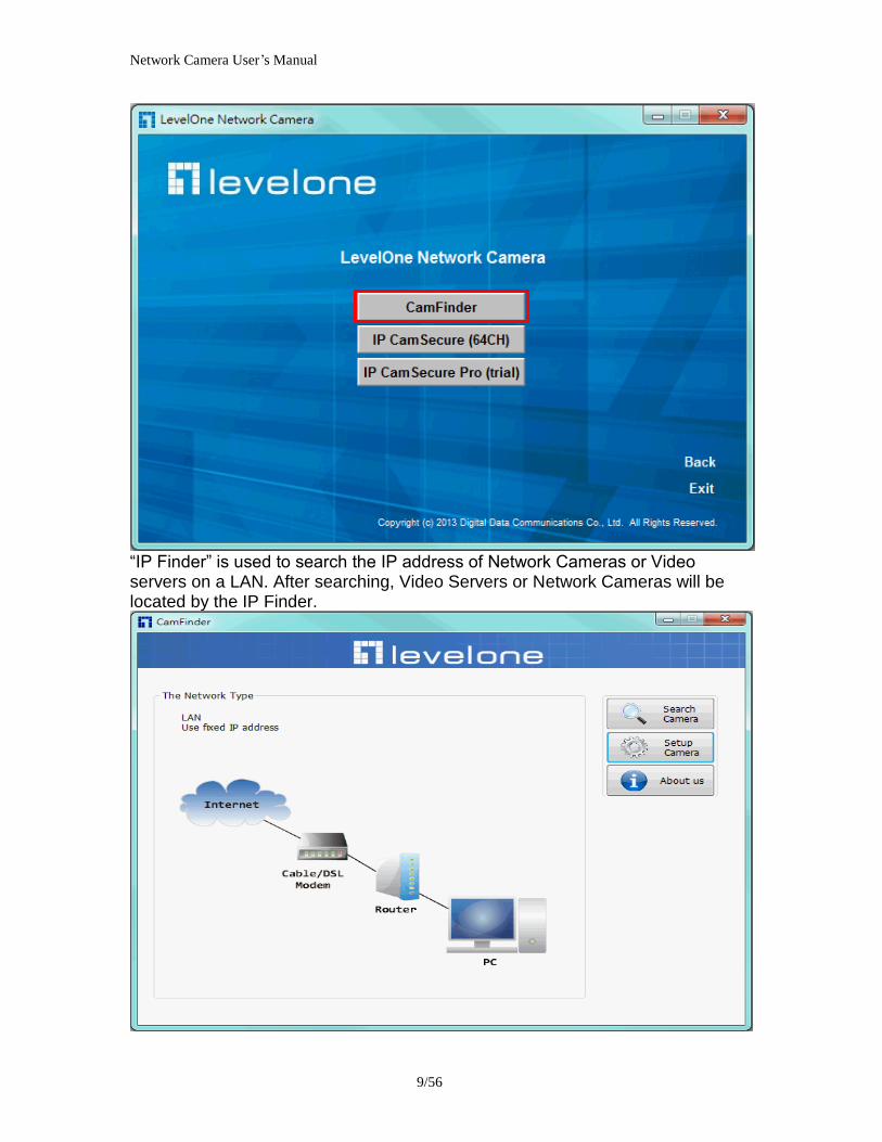
Network Camera Userrsquos Manual
1056
Search Camera
Click search Camera button the program will search for all family network devices on the same LAN After searching the main installer window will pop up Click on the MAC and model name which matches the product label on your device to connect to the Network Camera via Internet Explorer
Network Camera Userrsquos Manual
1156
Setup Camera Auto Install Wizard will be started and that it can auto guide through the installation process Press the ldquoNextrdquo button execute next process For more information please refer to the Network section on page 31
Network Camera Userrsquos Manual
1256
Network Camera Userrsquos Manual
1356
Network Camera Userrsquos Manual
1456
Network Camera Userrsquos Manual
1556
Bonjour program Safari browser supports Bonjour search program the will search for all family network devices on the same LAN
Network Camera Userrsquos Manual
1656
C2mylevel1com (Free DDNS service) 1 When you want to connect the network camera over Internet you can use the service ldquoC2mylevel1comrdquo The ldquoip-discoverycomrdquo is a free DDNS server for this camera Make sure that the router must start UPnP and DHCP server functions You can get the domain name which you wish very easily after registration In Network pagemdashDDNS settings of this camera you just input the host name you want and your e-mail address and click ldquoRegisterrdquo then you can have the hostname for this camera not longer than 20 seconds if the DDNS registration result is OK Then you can connect to this ip camera by httpXXXc2mylevel1com XXX the host name you type The HTTP port (get it automatically by c2mylevel1 server)
User password Default the password is last six number of the MAC To change ldquorootrdquo password at ldquoSecurity configurationrdquo can change the user password This ldquoUser passwordrdquo is entered in the c2mylevel1com Password Note You must set the ports between your router and camera manually if the registration is failed
Network Camera Userrsquos Manual
1756
Initial Access to the Network Camera
(1) For the initial access to the Network Camera in Windows the web browser may prompt for permission to install a new plug-in for the Network Camera This plug-in has been registered for certificate and is used to display the video in the browser
Users may click on to proceed
1 Click ldquoInstallrdquo and ldquoRunrdquo ActiveX controls 2 The video will be displayed
Network Camera Userrsquos Manual
1856
Primary userrsquos capability
Main Screen with Camera View The main page has three parts
1 Configuration functions The camera can be configured using these user interfaces
2 Connection control buttons These buttons provide the remote and local switching stream
3 Camera View What the camera sees Click the configuration in the bottom of left column to link to the configuration page
Configuration functions ldquoClient Settingsrdquo Clicking on this button links you to the client setting pages please check the following session for more details
ldquoConfigurationrdquo Please notes that only the administrator can access it ldquo Languagerdquo Click this button to choose a language for the user interface Language options are available in English traditional Chinese Simplified Chinese Japanese Spanish Portuguese French German Italiano
1
2
3
Network Camera Userrsquos Manual
1956
Camera view On the top of image shows the connecting type of the Network Camera and the current datetime
View capabilities
1 Click this button to capture and save still images The captured images will be
displayed in pop-up window Right-click the image and choose Save Picture As to save it in JPEG format
2 The button selection lets you open a digital zoom and to control the window to
enlarge a specified area in the camera view
3 Click this button to switch to full screen mode Press the ldquoEscrdquo key to switch back to normal mode
4 Click on this button freeze the video and playing when you click again
5 Click on this button stop video output
6 Use this functionyou can record video in your PC by browser directly The files
format will be in MP4
7 Click on this button adjust the audio volume amp Latency
8 Click on this button switch Mute OnOff
9 Click on this button to adjust the Function ldquo2-way audiordquo to be EnableDisable Enable this function request insert an external speaker The server can play sound from the client and receive sound from the environment and send to client
10 Click on this button to adjust the Microphone volume
Network Camera Userrsquos Manual
2056
11 Click on this button switch Microphone Mute OnOff Connection control buttons
1 ldquoConnectionrdquo User can choose Remote or Local mode for best connection quality Proposal Internet environment switch Remote mode
2 ldquoVideo Streamrdquo User can choose stream1 or stream2
Network Camera Userrsquos Manual
2156
Client Setting
1 ldquoIntranet Protocol Optionsrdquo Setting camera in intranet mode of protocol ldquoUDPrdquo Select use UDP protocol connect camera ldquoTCPrdquo Select use TCP protocol connect camera ldquoHTTPrdquo Select use HTTP protocol connect camera
2 ldquoInternet Protocol Optionsrdquo Setting camera in internet mode of protocol ldquoUDPrdquo Select use UDP protocol connect camera ldquoTCPrdquo Select use TCP protocol connect camera ldquoHTTPrdquo Select use HTTP protocol connect camera
3 ldquoRecording optionsrdquo Users can record live video as they are watching by
clicking start MP4 Recording on the main page Here you can specify the storage destination and file name
ldquoFolderrdquo Specify the storage destination for the recorded video files ldquoFile name prefixrdquo Enter the text that will be appended to the front of the video
file name ldquoAdd date and time suffix to file namerdquo Select this option to append the date
and time to the end of the file name
Network Camera Userrsquos Manual
2256
NOTEProtocol Options which allows choices on connection protocol between client and
server There are three protocols choices to optimize your usage ndash UDP TCP HTTP The UDP protocol allows for more real-time audio and video streams However some packets may be lost due to network burst traffic and images may be obscured The HTTP protocol allows for less packet loss and produces a more accurate video display The downside with this protocol is that the real-time effect is worse than that with the UDP protocol The TCP guarantees the complete delivery of streaming data and thus provides better video quality However the real-time effect is not as good as that of the UDP protocol If no special need is required UDP protocol is recommended Generally speaking the client choice will be in the order of UDP rarr HTTP After the Network Camera is connected successfully ldquoProtocol Optionrdquo will indicate the selected protocol The selected protocol will be recorded in the users PC and will be used for the next connection If the network environment is changed or the user wants to let the web browser to detect again manually select the UDP and TCP protocol save and return HOME to re-connect
Network Camera Userrsquos Manual
2356
Definitions in Configuration
Please note that only the Administrator can access the system configuration Each category in the left column will be explained on the following pages
System parameters
1 ldquoGeneral Settingrdquo
(1) ldquoHost namerdquo The text displays the title on the top of the main page
Firmware version
Network Camera Userrsquos Manual
2456
2 ldquoTime Settingrdquo (1) ldquoTime zonerdquo Choose a time zone from the down arrow
(2) ldquoDaylight savingrdquo For summertime It will be one hour ahead
(3) ldquoCurrent Timerdquo Network camera set the current time
(A) ldquoKeep current date and timerdquo Click on this to keep the current date and time of the Network Camera An internal real-time clock maintains the date and time even when the power of the system is turned off
(B) ldquoSync with computer timerdquo Synchronize the date and time in the Network Camera according to the local computer
(C) ldquoManualrdquo Adjust the date and time by the Administrator
(D) ldquoAdjust by NTP serverrdquo Synchronize the time according NTP server over the Internet whenever the Network Camera is switched on It fails if the assigned time-server cannot be found
(a) ldquoNTP serverrdquo Assign the IP address or domain name of the time-server Leaving the text box blank connects the Network Camera to the default time-servers
(b) ldquoUpdate intervalrdquo Select 0 ~ 23 hours update with the time on the NTP server
3 ldquoDI statusrdquo Please go to Application page for setting the DI
Network Camera Userrsquos Manual
2556
Security
Security setting The administrator account name is ldquorootrdquo which is permanent and can not be deleted If you want to add more accounts in the Manage User column please set a password for the ldquorootrdquo account first 1 ldquoChange root passwordrdquo Change the Administratorrsquos password by typing in the new password identically in both text boxes The typed entries will be displayed as asterisks for security purposes After pressing ldquofinishrdquo the web browser will ask the Administrator for the new password to access
2 ldquoManage privilegerdquo You can modify the manage privilege of operators or viewers Check or uncheck the item then click finish to enable the settings
3 ldquoManage userrdquo (1) ldquoAdd a new userrdquo Administrators can add up to 20 user accounts
(A) Input the new userrsquos name and password (B) Select the privilege level for the new user account Click Finish to enable the
setting
(2) ldquoDelete a userrdquo Select an existing user name Click Finish to enable the setting
Network Camera Userrsquos Manual
2656
(3) ldquoUpdate a existing userrdquo Select an existing user name Administrators can modify userrsquos password and privilege Click Finish to enable the setting
Access rights are sorted by user privilege (Administrator Operator and Viewer) Only administrators can access the Configuration page Operators cannot access the Configuration page but can use the URL Commands to get and set the value of parameters Viewers access only the main page for live viewing
Network
Any changes made on this page will restart the system in order to validate the changes Make sure every field is entered correctly before clicking on ldquofinishrdquo
Network Camera Userrsquos Manual
2756
Network Setting ldquoLANrdquo amp ldquoPPPoErdquo The default type is LAN Select PPPoE if using ADSL
1 LAN
The default status is Get IP address automatically This could be tedious to perform software installation whenever the Network Camera starts Therefore once the network is set especially for the IP address should be entered correctly Select Use fixed IP address then the Network Camera will skip installation The Network Camera will automatically restart and operate normally after a power outage You can run IP installer to check the IP address assigned to the Network Camera if the IP address is forgotten or you can use the UPnP function provided by the Network Camera (MS Windows XP provides UPnP function at My Network Place)
(1) ldquoGet IP address automaticallyrdquo (2) ldquoUse fixed IP addressrdquo
- ldquoIP addressrdquo This is necessary for network identification - ldquoSubnet maskrdquo This is used to determine if the destination is in the same subnet The default value is ldquo2552552550rdquo - ldquoDefault routerrdquo This is a gateway used to forward frames to destinations in a different subnet Invalid router setting will fail the transmission to destinations in different subnet - ldquoPrimary DNSrdquo The primary domain name server that translates hostnames into IP addresses - ldquoSecondary DNSrdquo Secondary domain name server backups the Primary DNS - ldquoEnable UPnP presentation amp port forwardingrdquo Enable UPnP ability - ldquoHttp portrdquo This can be typed besides the default Port 80 Once the port is changed the users must make sure the change for the connection is successful For instance when the Administrator changes the HTTP port of the Network Camera which IP address is 192168020 from 80 or 1025 to 65535 the users must type in the web browser ldquohttp1921680208080rdquo instead of ldquohttp192168020rdquo
- ldquoRTSP Portrdquo RTSP port can be typed besides the default Port 554 - ldquoRTP Portrdquo The RTP port can be typed besides the default Port 54
Note Please set Video RTP port in even number after default value port 54 Then
Video RTCP potAudio RTP portAudio RTCP port will automatically set the
values in ascending
- ldquoRTSP Streaming access namesrdquo The RTSP streaming currently supports video only audio only and audiovideo To use the audiovideo stream type the URL asldquortsp613012543liveNsdprdquo
2 PPPoE If using the PPPoE interface you should fill the following settings from ISP
(1) ldquoUser namerdquo The login name of PPPoE account (2) ldquoPasswordrdquo The password of PPPoE account (3) ldquoConfirm passwordrdquo Input password again for confirmation
Network Camera Userrsquos Manual
2856
DDNS Setting 1 ldquoEnable DDNSrdquo This option turns on the DDNS function
2 ldquoip-discoveryrdquo In the Register column fill in the Host name (xxxx ip-discovery) Email Key and Confirm Key then click Register After a host name has been successfully created a success message will be displayed in the DDNS Registration Result column and messaging E-mail
3 ldquo3rd party DDNSrdquo This is enable or disable 3rd party DDNS 4 ldquoProviderrdquo The provider list contains hosts that provide DDNS services Please connect to the service providerrsquos website to make sure the service charges
5 ldquoHost Namerdquo If the User wants to use DDNS service this field must be filled Please input the hostname that is registered in the DDNS server
6 ldquoUser namerdquo The Username or E-mail field is necessary for logging in the DDNS server or notify the User of the new IP address Note when this field is input as ldquoUser namerdquo the following field must be input as ldquoPasswordrdquo
7 ldquoPasswordrdquo Please input the password or key to get the DDNS service
8 ldquofinishrdquo Click on this button to save modify settings for the DDNS service
Network Camera Userrsquos Manual
2956
Access list
Access list setting 1 How to control access permission by verifying the client PCrsquos IP
address General Settings General Settings
Add a rule to configure an AllowedDenied list Click Add to add a rule
Network Camera Userrsquos Manual
3056
to AllowedDenied list There are three types of rules for user to set up ldquoSinglerdquo This rule allows the user to add an IP address to the AllowedDenied list For example
ldquoNetworkrdquo This rule allows the user to assign a network address and corresponding subnet mask to the AllowDeny List The IP address is written in the CIDR format For example
Network Camera Userrsquos Manual
3156
ldquoRangerdquo This rule allows the user to assign a range of IP addresses to the AllowDeny List This rule is only applied to IPv4 For example
Network Camera Userrsquos Manual
3256
Audio and Video setting
Network Camera Userrsquos Manual
3356
General Setting 1 ldquoColor moderdquo Select use color or monochrome video display
2 ldquoVideo orientationrdquo The orientation of video
(1) ldquoFliprdquo Vertically rotate the video
(2) ldquoMirrorrdquo Horizontally rotates the video
3 ldquoEnvironmentrdquo The orientation of video
(1) ldquoindoorrdquo This option is usually selected when the Network Camera is placed in indoor environments
(2) ldquooutdoorrdquo This option is usually selected when the Network Camera is placed in outdoor environments
4 ldquoPower freqrdquo Select 50 Hz or 60Hz power line frequency
The fluorescent light will flash according to the power line frequency that
depends on local utility Change the frequency setting to eliminate uncomfortable flash image when the light source is only fluorescent light
Video Setting 1 ldquoContrastrdquo Adjust the image contrast level which ranges from -5 to +5 The default value is set to 0
2 ldquoBrightnessrdquo Adjust the image brightness level which ranges from -5 to +5 The default value is set to 0
3 ldquoSaturationrdquo Adjust the image saturation level which ranges from -5 to +5 The default value is set to 0
4 ldquoSharpnessrdquo Adjust the image sharpness level which ranges from -5 to +5 The default value is set to 0
5 ldquoEVrdquo Exposure value represent the expected target value of the luminance of
the weighting result of AE windows in the image and its tolerance as offset
6 ldquoGainrdquo In the slide bar of Gain there are also two sliders which represent the
limitations to control the maximum gain value and the minimum one respectively Normally the minimum value is to 1x for better quality
Network Camera Userrsquos Manual
3456
Exposure setting Here it provides 3 mode Auto Backlight and Customized Auto and
Backlight modes are 2 default settings for general purpose and backlight scene
respectively
Customized mode relates to the grid window above can be pointed on for
interesting areas Within the mode Customized 1615 grids windows can be chosen to match wherewhat you are interested in Push down left-button of mouse and drag to draw the grids for interesting areas or push down right-button of mouse and drag to clean the grids for insignificant areas
ldquoTarget Luminance and Offsetrdquo
These two slide bar Target Luminance and Offset represent the expected
target value of the luminance of the weighting result of AE windows in the image and its tolerance as offset For example target luminance is set to 100 and target offset is set to 20 that means the average luminance of the AE window should be in the range from 80 to 120 (100plusmn(10 When the actual luminance does not meet this range the AE function will adjust shutter and gain to meet it as possible In some extreme cases it cannot reach the target because the environment is too bright or dark When the environment is not consistent eg with big moving objects and the offset is too narrow the AE will act more frequently that will cause the background of view inconsistent The offset value is recommended to set 15~25 of target luminance
Network Camera Userrsquos Manual
3556
ldquoGainrdquo
In the slide bar of Gain there are also two sliders which represent the limitations
to control the maximum gain value and the minimum one respectively Normally the minimum value is to 1x for better quality It is not allowed if the maximum slider and the minimum one are set to the same value without adjustable interval Besides the noise will be increased if the actual gain is too large When the max slider is dragged over sensors max gain the slide bar will become deep blue to represent it will apply Mozart 3s digital gain which extend the max gain for very low light
ldquoShutter Speedrdquo
There are 2 fields minimal and maximal time for the range of Shutter Speed
The precision of the parameter is 11000000 sec but it is NOT actual precision of the shutter speed of the sensor The actual precision of the shutter speed depends on each sensorrsquos specification Here it will be rounded to approach sensorrsquos effective exposure time To avoid flickering or banding phenomenon under fluorescent light the actual shutter speed will be locked at 1120 160
130 if Power Line Frequency is 60Hz or 1100 150 125 if Power Line
Frequency is 50Hz The setting of Power Line Frequency is on the sub-tab Video
and Audio The exposure may not be stable if the maximum value and the minimum one are set to the same value without adjustable interval Besides the frame rate will drop down if the actual shutter speed is too slow to meet expected frame rate
Noise reduction
Provides 2D and 3D features
Wide Dynamic Range Enable Wide Dynamic Range auto in different level to improve the exposure when both bright and dark areas simultaneously in the field of view of the camera The default is off
Infrared Led Setting 1 ldquoInfrared LED Controlrdquo IR led for Day and Night (Option) User can turn onoff the built-in IR led This function is very useful under low illumination environment
(1) ldquoAutordquo Select IR sensitivity from 0 to 4
(2) ldquoManualrdquo Turn onoff the IR led manually
- ldquoTurn onrdquo Turn on led - ldquoTurn offrdquo Turn off led
2 ldquoLow lux moderdquo The video quality will be improved when the camera is in low lux environment (1) ldquoDisable dark moderdquo Disable low lux mode
(2) ldquoEnable dark moderdquo Enable low lux mode
Network Camera Userrsquos Manual
3656
Video output Setting 1 ldquovideo outputrdquo Can switch between NTSC and PAL
Audio Setting 1 ldquoMuterdquo Audio mute
2 ldquoMicrophone rdquo External microphone
3 ldquoMic Volumerdquo Adjust microphone volume which ranges from 1 to 46
Video record
Schedule mode
(1) ldquoEvery dayrdquo EnableDisable every day application
(2) ldquoWeek dayrdquo EnableDisable week day application
(3)ldquoSelected dayrdquo EnableDisable selected day application
Schedule information
(1) Enter the ldquoStart timerdquo and ldquoStop timerdquo for day mode Note that the time format is [hhmm] and is expressed in 24-hour clock time By default the start and end time of day mode are set to 010000 and 235959
Network Camera Userrsquos Manual
3756
(2)ldquoSunrdquoldquoMonrdquoldquoTuerdquoldquoWedrdquoldquoThurdquoldquoFrirdquoldquoSatrdquo Select the days of the week to perform the application
(3) ldquoStart dayrdquo and ldquoStart timerdquo as the start timing the time ldquoEnd dayrdquo and ldquoEnd timerdquo as the end timing the time
(4) ldquoEnable cyclic recordingrdquo The cyclic recording function is enabled during the transaction stage when a storage space is full and the incoming streaming data is about to overwrite the previously saved videos
Record parameters (1)Source Select a stream for the recording source
(2)Recording interval Select the recording time interval
(3)Prefix file name You can setting the file name and enable or disable to add the date and time on file name
Response mode There are two choices of server types available NAS SD Card Select the item to display the detailed configuration options
(1)rdquoNASrdquo
--ldquoNAS server addressrdquo Enter IP address of the NAS server
--ldquoNAS shared directoryrdquo Enter the NAS shared directory path --ldquoWorkgrouprdquo Enter the NAS workgroup parameter --ldquoUser accountrdquo Enter the login name of the NAS account --ldquoUser passwordrdquo Enter the password of the NAS account Note Video record with the Application must be set to the same shared directory
path If you would like do detail recording settings or multi-channel recording please install bundled 64CH recording software in CD
Network Camera Userrsquos Manual
3856
Stream
Audio codec setting
(1)ldquoAudio codec typerdquo There are two choices of audio codec types
available rdquoAMRrdquo ldquoAACrdquo and rdquoG711rdquo
(2) ldquoBit raterdquo -- ldquoAMRrdquo The bit rates are selectable at the following rates
47505150590067007400795010200 and 12200
-- ldquoAACrdquo The bit rates are selectable at the following rates 8Kbps16Kbps 24Kbps and 32Kbps
-- ldquoG711rdquo pcmu and pcma
Video codec setting (1) ldquoSelect Streamrdquo The Network Camera supports ldquoStream 1rdquoand ldquoStream 2rdquo
(2) ldquoVideo codecrdquo The Network Camera supports three kind of video compression mode ldquoH264rdquo or ldquoMPEG4rdquo or ldquoMJPEGrdquo User can choose one of
Network Camera Userrsquos Manual
3956
these compression modes based on requirement or application
(3) ldquoVideo sizerdquo Click the down arrow to choose the quality of image (1920x1080 1280x1024 1280x800 640x480 320x240 176x144)
(4) ldquoConnection typerdquo User can select this button to choose the better video amp links quality (Internet mode or Intranet mode)
(5) ldquoFrame raterdquo This limits the maximal refresh frame rate per second Set the frame rate higher for a smoother video quality
(6) ldquoIntra frame periodrdquo Determine how often to plant an ldquoI framerdquo The shorter the duration the more likely you will get a better video quality but at the cost of higher network bandwidth consumption
(7) ldquoVideo Quality typerdquo Setting optimizes bandwidth utilization and video quality
-- ldquoConstant bit raterdquo User can adjust the video quality from 20 Kbps to 12 Mbps
-- ldquoFixed qualityrdquo user can select from lowest quality to get best quality according The ldquoQualityrdquo are selectable at the following rates From 1 to 20
Snapshot and time display setting Adjust the photo size specifications and choose whether to mark time on the video and photo
Network Camera Userrsquos Manual
4056
Application
Schedule mode
(1) ldquoEvery dayrdquo EnableDisable every day application
(2) ldquoWeek dayrdquo EnableDisable week day application
(3) ldquoSelected dayrdquo EnableDisable selected day application
Schedule information (1) Enter the ldquoStart timerdquo and ldquoStop timerdquo for day mode
Note that the time format is [hhmmss] and is expressed in 24-hour clock time By default the start and end time of day mode are set to 010000 and 235959
(2) ldquoSunrdquoldquoMonrdquoldquoTuerdquoldquoWedrdquoldquoThurdquoldquoFrirdquoldquoSatrdquo Select the days of the week to perform the application
(3) ldquoStart dayrdquo and ldquoStart timerdquo as the start timing the time ldquoEnd dayrdquo and ldquoEnd timerdquo as the end timing the time
Trigger mode
(1) ldquoVideo motion detectionrdquo EnableDisable video motion application (2) ldquoPeriodicallyrdquo This option allows the Network Camera to trigger
periodically for every other defined minute
Network Camera Userrsquos Manual
4156
(3) ldquoDigital inputrdquo This option allows the Network Camera to use an external digital input device or sensor as a trigger source Depending on your application there are many choices of digital input devices on the market which helps to detect changes in temperature vibration sound and light etc
parameters
(1) ldquoMotion parametersrdquo Higher sensitivity and small threshold will allow easier motion detection
(2) ldquoPeriod parametersrdquo This option allows the Network Camera to trigger periodically for every other defined seconds Up to 999 seconds are allowed
(3) ldquoDigital input parametersrdquo Select the digital input type and set trigger time
Media mode There are four choices of media types available ldquoSnapshotrdquo ldquoMessagerdquo ldquoRecord(Motion Detection only)rdquo and ldquoSystem logrdquo
Snapshot amp Record file setting You can setting the file name and enable or disable to add the date and time on file name Can setting the digital output duration seconds Response mode There are four choices of server types available Email FTP NAS and SD Card storage Select the item to display the detailed configuration options
(1)ldquoEmailrdquo -- ldquoEmail security moderdquo If your SMTP server requires a secure connection (SSL or TLS) check This server requires a secure connection (SSL or TLS) -- ldquoSender emailrdquo address Enter the email address of the sender -- ldquoRecipient emailrdquo address Enter the email address of the recipient
-- ldquoServer addressrdquo Enter the domain name or IP address of the email server
--ldquoUser namerdquo Enter the user name of the email account if necessary
--ldquoPasswordrdquo Enter the password of the email account if necessary
--ldquoServer portrdquo The default mail server port is set to 25 You can also manually set another port
(2)rdquoFTPrdquo -- ldquoServer addressrdquo Enter the domain name or IP address of the FTP server
-- ldquoServer portrdquo By default the FTP server port is set to 21
-- ldquoUser namerdquo Enter the login name of the FTP account
-- ldquoPasswordrdquo Enter the password of the FTP account
-- ldquoFTP folder namerdquo Enter the folder where the media file will be placed If the folder name does not exist the Network Camera will create one on the FTP server
(3)rdquoHTTP rdquo
-- ldquoURLrdquo Enter the URL of the HTTP server
-- ldquoUser accountrdquo Enter the user name if necessary -- ldquoUser passwordrdquo Enter the password if necessary
(4)rdquoNASrdquo --ldquoNAS server addressrdquo Enter IP address of the NAS server
--ldquoNAS shared directoryrdquo Enter the NAS shared directory path
Network Camera Userrsquos Manual
4256
--ldquoWorkgrouprdquo Enter the NAS workgroup parameter --ldquoUser accountrdquo Enter the login name of the NAS account --ldquoUser passwordrdquo Enter the password of the NAS account Note Video record with the Application must be set to the same shared directory
path If you would like do detail recording settings or multi-channel recording please install bundled 64CH recording software in CD
Network Camera Userrsquos Manual
4356
Storage
Manage the storage device
S torage Status Here show the storage device information
NAS server setting
1
2
3
Network Camera Userrsquos Manual
4456
(1) ldquoNAS Host namerdquo Choose and input the NAS Host name of this camera
(2) ldquoWorkgrouprdquo Input the name of Workgroup You can see the NAS Host name you input in the same workgroup with your PC Then you can connect to this device and download the files easily from SD card which is inserted to this camera
File operation Move the mouse over the file Press the mouse right button that Right-click menu is displayed You can delete files Move the mouse over the directory Press the mouse left button that the file structure expand Press the mouse right button that Right-click menu is displayed You can choose upload or delete files NOTEAllow the user to upload or delete files when the storage device is not write-
protected If the SD card canrsquot be detected please link to the following URL httpwwwsdcardorgconsumersformatter to download the ldquoSD Formatter Kitrdquo formatting your SD card
Network Camera Userrsquos Manual
4556
Syslog
The Network camera supports log the system messages on remote server The protocol is compliant to RFC 3164 If you have external Linux server with sys log service use ldquo-rrdquo option to turn on the facility for receiving log from remote machine Or you can use some software on Windows that is compliant to RFC 3164 An example is Kiwi Syslog Daemon Visit httpwwwkiwisyslogcomkiwi-syslog-daemon-overview Check ldquoSetuprdquo and ldquoEnablerdquo then input the ldquoIP addressrdquo and ldquoportrdquo number of the log server to enable the remote log facility In the ldquoCurrent logrdquo it displays the current system log file The content of the log provides useful information about configuration and connection after system boot- up
ldquofinishrdquo Click on this button to save modify settings
Network Camera Userrsquos Manual
4656
Status and Parameters
User can find a lot of information about the system such as ldquoUpnp port forwardingrdquo
ldquoTraversing NATrdquo ldquoPublic IPrdquo and so on User also can get the number of current viewer of the Network Camera here
Network Camera Userrsquos Manual
4756
Maintenance
1 ldquoReboot systemrdquo The ldquoRebootrdquo button will reboot the Network Camera Itrsquos useful while the Network Camera got problem 2 ldquoRestore systemrdquo Click on ldquoRestorerdquo button on the configuration page to restore the factory default settings Restore all settings to factory default except settings in ldquoNetwork type rdquo and ldquoRoot Passwordrdquo The system will restart and require the installer program to set up the network again
3 ldquoCalibraterdquo Recalibrate the auto focus position to the default range to recover the tolerance caused by some external forces 4 ldquoExportImport filerdquo -- Export setting backup file Click to export all parameters for the device and user-defined scripts
-- Upload setting backup file Click Browsehellip to upload a setting backup file Please note that the model and firmware version of the device should be the same as the setting backup file If you have set up a fixed IP or other special settings for your device it is not suggested to upload a settings backup file
4 ldquoUpgrade firmwarerdquo Select the firmware file and click upgrade button Please be aware that you should not turn off the power during updating the firmware and wait for finish message
Network Camera Userrsquos Manual
4856
Warning The upgrade firmware procedure cannot be interrupted If the power
andor network connection are broken during the procedure it might possibly cause serious damage to the Network Camera
Note When upgrade firmware please wait for 120~210 seconds and then you can connect to Network Camera again The system will restart and require the installer program to set up the network again
Network Camera Userrsquos Manual
4956
Appendix
A Troubleshooting amp Frequently Asked Questions Q1 Status led does not light up
A1 First make sure that「ConfigurationgtSystemgtTurn off the LED indicator」is disabled
If it is check the item and the led should light up Second if red led does not light up please check that the power adapter in the package is plugged correctly And last if green led does not light up please check that category 5 UTP cable is plugged correctly If the problem is still not solved please contact your dealer for further help
Q2 What kind of Ethernet cable is used by network camera
A2 The network Camera uses Category 5 UTP cable allowing 10 andor 100 Base-T networking
Q3 The Network Camera will be installed and work if a firewall exists on
the network
A3 There are two way to set up the IP camera at Internet (1) By UPnP Port Forwarding 1 Select an IP router It must support UPnP port forwarding and enable this function
first
2 Connect camera RJ45 cable to IP router and the router is also connected to Internet
3 Plug power cord to camera
4 Go to camera Network page Enable UPnP port forwarding
5 Check camera status we can see the ports had been successfully opened
Network Camera Userrsquos Manual
5056
6Type IP address8080 at browser Then you can see camera through Internet
7You can also type the ddns name at below label of camera on browser URL field For example you may type ah00001ip-discoverycom8080 (2) By Setting Port Forwarding Manually 1 Select a router Set the port forwarding as following
Network Camera Userrsquos Manual
5156
PS Port 80 is HTTP Port port 53 is stream port port 554 is RTSP port and port 443 is HTTPS port 2Go to camera Network page Disable UPnP port forwarding function
Network Camera Userrsquos Manual
5256
3 Type IP address at browser Then you can see camera through Internet
4 You can also type the ddns name at below label of camera on browser URL field For example you may type ah00001ip-discoverycom
Note The firewall software at PC may block the transfer of network camera Please remove or stop the kind software
Q4 How can I find the network camera in the local area network
A4 By using the IP Finder2 program or using UPnP to find it
Q5 IP Finder2 program cannot find Network Camera in the local area
network at first time
A5 Make sure the subnet of network camera is same as your PC If the local area network supports DHCP the camera is ldquoGet IP address automaticallyrdquo in the ldquoNetworkrdquo page default If the local area network does not support DHCP change your PC IP address to ldquo1921680xxxrdquo
Network Camera Userrsquos Manual
5356
Q6 How can I restore the network camera to default value
A6 Use a gem clip to press on the inside button Network camera begins to restore default value You can also press the button ldquoFactoryrdquo in ldquoMaintenancerdquo page to restore the default value
Q7 I cannot play the recorded video file
A7 Install the audio codec in the CD and use the Windows Media Player 10 or later to play the ASF or AVI file recorded by the network camera
Q8 Infrared led does not light up
A8 Check「ConfigurationgtAudio and VideogtInfrared LED Control」 is ldquoAutordquo or
ldquoManual》Turn onrdquo
Q9 The network camera cannot focus accurately
A9 (1) The lens is dirty or dust is attached Clean the lens with lens cleaner And then adjust the camera focus manually (2) The image may be out of focus If the object is too near move the object away from Network Camera
Q10 The cover of network camera is warm Is it normal
A10 Network camera is a precision device The internal material has the operational temperature and it is normal when user touch the cover feels warm It is recommended to put the network camera at aired place and not put at any other device
Q11 The process of upgrade firmware abort
A11 Contact your dealer for further help
Q12 Cannot access the login page and other web pages of Network
Network Camera Userrsquos Manual
5456
Camera from Internet Explorer
A12 bull May be due to the network cable Try correcting your network cable and configuration Test the network interface by connecting a local computer to the Network Camera via a crossover cable bull Make sure the Internet connection and setting is ok bull Make sure enter the IP address of Internet Explorer is correct If Network Camera has a dynamic address it may have changed since you last checked it bull Network congestion may prevent the web page appearing quickly Wait for a while The IP address and Subnet Mask of the PC and Network Camera must be in the same class of the private IP address on the LAN bull Make sure the http port used by the Network Camera default=80 is forward to the Network Camerarsquos private IP address bull The port number assigned in your Network Camera might not be available via Internet Check your ISP for available port bull The proxy server may prevent you from connecting directly to Network Camera set up not to use the proxy server bull Confirm that Default Gateway address is correct bull The router needs Port Forwarding feature Refer to your routers manual for details bull Packet Filtering of the router may prohibit access from an external network Refer to your routers manual for details bull Access Network Camera from the Internet with the global IP address of the router and port number of Network Camera bull Some routers reject the global IP address to access Network Camera on the same LAN Access with the private IP address and correct port number of Network Camera bull When you use DDNS you need to set Default Gateway and DNS server address bull If itrsquos not working after above procedure reset Network Camera to default setting and installed it again bull Maybe the IP Address of the Network Camera is already being used by another device or computer bull If the problem is not solved the Network Camera might be faulty Contact your dealer for further help
Network Camera Userrsquos Manual
5556
B Technical specifications
- System RAM 4G bit DDRⅢ
ROM 16MB Flash ROM
- Camera specification 127 inch color CMOS sensor Resolution 1920x1080 10LuxF20 AGC AWB AEC
- Infrared Led High power IR Leds 25~30 M visible AutoManual mode
- Lens 3X optical zoom lens auto iris auto focus f = 28~ 12mm F18 Fov(D) 136deg ~ 39deg
- Protocol TCPIP HTTPUDP SMTP FTP DDNS UPnP Telnet NTP PPPoE RTSP RTPRTCPDHCP and DNS
- Video Resolution Up to 30 frames at 176x144 Up to 30 frames at 320x240 Up to 30 frames at 640x480 Up to 30 frames at 1280x800 Up to 30 frames at 1280x1024 Up to 30 frames at 1920x1080
- Algorithm supported H264MPEG4MJPEG dual codec for streaming video JPEG for still image
- Audio AMRAACG711 External MIC input 2-way audio
- Physical 10 baseT100 baseT and 1000 baseT Fast
Ethernet auto negotiation
- Power Input 100-240VAC 5060Hz 07A Output 12VDC 15A Consumption Max 12 W Support 8023af compliant Power over Ethernet
- EMI amp Safety CE FCC
- Dimension Length 165mm Diameter 75mm
- Operating Environment Temperature -20 ~ 50
Humidity 85 RH
- Weight NET 600g With bracket 800g
Network Camera Userrsquos Manual
5656
Notification of Compliance Appendix C
Europe - EU Declaration of Conformity
For complete DoC please visit httpgloballevel1comdownloadsphpaction=init
GPL License Agreement GPL may be included in this product to view the GPL license agreement goes to httpdownloadlevel1comlevel1gplGPLpdf For GNU General Public License (GPL) related information please visit httpgloballevel1comdownloadsphpaction=init
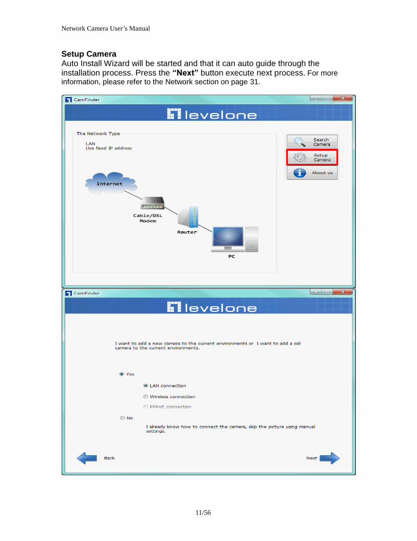
Network Camera Userrsquos Manual
1256
Network Camera Userrsquos Manual
1356
Network Camera Userrsquos Manual
1456
Network Camera Userrsquos Manual
1556
Bonjour program Safari browser supports Bonjour search program the will search for all family network devices on the same LAN
Network Camera Userrsquos Manual
1656
C2mylevel1com (Free DDNS service) 1 When you want to connect the network camera over Internet you can use the service ldquoC2mylevel1comrdquo The ldquoip-discoverycomrdquo is a free DDNS server for this camera Make sure that the router must start UPnP and DHCP server functions You can get the domain name which you wish very easily after registration In Network pagemdashDDNS settings of this camera you just input the host name you want and your e-mail address and click ldquoRegisterrdquo then you can have the hostname for this camera not longer than 20 seconds if the DDNS registration result is OK Then you can connect to this ip camera by httpXXXc2mylevel1com XXX the host name you type The HTTP port (get it automatically by c2mylevel1 server)
User password Default the password is last six number of the MAC To change ldquorootrdquo password at ldquoSecurity configurationrdquo can change the user password This ldquoUser passwordrdquo is entered in the c2mylevel1com Password Note You must set the ports between your router and camera manually if the registration is failed
Network Camera Userrsquos Manual
1756
Initial Access to the Network Camera
(1) For the initial access to the Network Camera in Windows the web browser may prompt for permission to install a new plug-in for the Network Camera This plug-in has been registered for certificate and is used to display the video in the browser
Users may click on to proceed
1 Click ldquoInstallrdquo and ldquoRunrdquo ActiveX controls 2 The video will be displayed
Network Camera Userrsquos Manual
1856
Primary userrsquos capability
Main Screen with Camera View The main page has three parts
1 Configuration functions The camera can be configured using these user interfaces
2 Connection control buttons These buttons provide the remote and local switching stream
3 Camera View What the camera sees Click the configuration in the bottom of left column to link to the configuration page
Configuration functions ldquoClient Settingsrdquo Clicking on this button links you to the client setting pages please check the following session for more details
ldquoConfigurationrdquo Please notes that only the administrator can access it ldquo Languagerdquo Click this button to choose a language for the user interface Language options are available in English traditional Chinese Simplified Chinese Japanese Spanish Portuguese French German Italiano
1
2
3
Network Camera Userrsquos Manual
1956
Camera view On the top of image shows the connecting type of the Network Camera and the current datetime
View capabilities
1 Click this button to capture and save still images The captured images will be
displayed in pop-up window Right-click the image and choose Save Picture As to save it in JPEG format
2 The button selection lets you open a digital zoom and to control the window to
enlarge a specified area in the camera view
3 Click this button to switch to full screen mode Press the ldquoEscrdquo key to switch back to normal mode
4 Click on this button freeze the video and playing when you click again
5 Click on this button stop video output
6 Use this functionyou can record video in your PC by browser directly The files
format will be in MP4
7 Click on this button adjust the audio volume amp Latency
8 Click on this button switch Mute OnOff
9 Click on this button to adjust the Function ldquo2-way audiordquo to be EnableDisable Enable this function request insert an external speaker The server can play sound from the client and receive sound from the environment and send to client
10 Click on this button to adjust the Microphone volume
Network Camera Userrsquos Manual
2056
11 Click on this button switch Microphone Mute OnOff Connection control buttons
1 ldquoConnectionrdquo User can choose Remote or Local mode for best connection quality Proposal Internet environment switch Remote mode
2 ldquoVideo Streamrdquo User can choose stream1 or stream2
Network Camera Userrsquos Manual
2156
Client Setting
1 ldquoIntranet Protocol Optionsrdquo Setting camera in intranet mode of protocol ldquoUDPrdquo Select use UDP protocol connect camera ldquoTCPrdquo Select use TCP protocol connect camera ldquoHTTPrdquo Select use HTTP protocol connect camera
2 ldquoInternet Protocol Optionsrdquo Setting camera in internet mode of protocol ldquoUDPrdquo Select use UDP protocol connect camera ldquoTCPrdquo Select use TCP protocol connect camera ldquoHTTPrdquo Select use HTTP protocol connect camera
3 ldquoRecording optionsrdquo Users can record live video as they are watching by
clicking start MP4 Recording on the main page Here you can specify the storage destination and file name
ldquoFolderrdquo Specify the storage destination for the recorded video files ldquoFile name prefixrdquo Enter the text that will be appended to the front of the video
file name ldquoAdd date and time suffix to file namerdquo Select this option to append the date
and time to the end of the file name
Network Camera Userrsquos Manual
2256
NOTEProtocol Options which allows choices on connection protocol between client and
server There are three protocols choices to optimize your usage ndash UDP TCP HTTP The UDP protocol allows for more real-time audio and video streams However some packets may be lost due to network burst traffic and images may be obscured The HTTP protocol allows for less packet loss and produces a more accurate video display The downside with this protocol is that the real-time effect is worse than that with the UDP protocol The TCP guarantees the complete delivery of streaming data and thus provides better video quality However the real-time effect is not as good as that of the UDP protocol If no special need is required UDP protocol is recommended Generally speaking the client choice will be in the order of UDP rarr HTTP After the Network Camera is connected successfully ldquoProtocol Optionrdquo will indicate the selected protocol The selected protocol will be recorded in the users PC and will be used for the next connection If the network environment is changed or the user wants to let the web browser to detect again manually select the UDP and TCP protocol save and return HOME to re-connect
Network Camera Userrsquos Manual
2356
Definitions in Configuration
Please note that only the Administrator can access the system configuration Each category in the left column will be explained on the following pages
System parameters
1 ldquoGeneral Settingrdquo
(1) ldquoHost namerdquo The text displays the title on the top of the main page
Firmware version
Network Camera Userrsquos Manual
2456
2 ldquoTime Settingrdquo (1) ldquoTime zonerdquo Choose a time zone from the down arrow
(2) ldquoDaylight savingrdquo For summertime It will be one hour ahead
(3) ldquoCurrent Timerdquo Network camera set the current time
(A) ldquoKeep current date and timerdquo Click on this to keep the current date and time of the Network Camera An internal real-time clock maintains the date and time even when the power of the system is turned off
(B) ldquoSync with computer timerdquo Synchronize the date and time in the Network Camera according to the local computer
(C) ldquoManualrdquo Adjust the date and time by the Administrator
(D) ldquoAdjust by NTP serverrdquo Synchronize the time according NTP server over the Internet whenever the Network Camera is switched on It fails if the assigned time-server cannot be found
(a) ldquoNTP serverrdquo Assign the IP address or domain name of the time-server Leaving the text box blank connects the Network Camera to the default time-servers
(b) ldquoUpdate intervalrdquo Select 0 ~ 23 hours update with the time on the NTP server
3 ldquoDI statusrdquo Please go to Application page for setting the DI
Network Camera Userrsquos Manual
2556
Security
Security setting The administrator account name is ldquorootrdquo which is permanent and can not be deleted If you want to add more accounts in the Manage User column please set a password for the ldquorootrdquo account first 1 ldquoChange root passwordrdquo Change the Administratorrsquos password by typing in the new password identically in both text boxes The typed entries will be displayed as asterisks for security purposes After pressing ldquofinishrdquo the web browser will ask the Administrator for the new password to access
2 ldquoManage privilegerdquo You can modify the manage privilege of operators or viewers Check or uncheck the item then click finish to enable the settings
3 ldquoManage userrdquo (1) ldquoAdd a new userrdquo Administrators can add up to 20 user accounts
(A) Input the new userrsquos name and password (B) Select the privilege level for the new user account Click Finish to enable the
setting
(2) ldquoDelete a userrdquo Select an existing user name Click Finish to enable the setting
Network Camera Userrsquos Manual
2656
(3) ldquoUpdate a existing userrdquo Select an existing user name Administrators can modify userrsquos password and privilege Click Finish to enable the setting
Access rights are sorted by user privilege (Administrator Operator and Viewer) Only administrators can access the Configuration page Operators cannot access the Configuration page but can use the URL Commands to get and set the value of parameters Viewers access only the main page for live viewing
Network
Any changes made on this page will restart the system in order to validate the changes Make sure every field is entered correctly before clicking on ldquofinishrdquo
Network Camera Userrsquos Manual
2756
Network Setting ldquoLANrdquo amp ldquoPPPoErdquo The default type is LAN Select PPPoE if using ADSL
1 LAN
The default status is Get IP address automatically This could be tedious to perform software installation whenever the Network Camera starts Therefore once the network is set especially for the IP address should be entered correctly Select Use fixed IP address then the Network Camera will skip installation The Network Camera will automatically restart and operate normally after a power outage You can run IP installer to check the IP address assigned to the Network Camera if the IP address is forgotten or you can use the UPnP function provided by the Network Camera (MS Windows XP provides UPnP function at My Network Place)
(1) ldquoGet IP address automaticallyrdquo (2) ldquoUse fixed IP addressrdquo
- ldquoIP addressrdquo This is necessary for network identification - ldquoSubnet maskrdquo This is used to determine if the destination is in the same subnet The default value is ldquo2552552550rdquo - ldquoDefault routerrdquo This is a gateway used to forward frames to destinations in a different subnet Invalid router setting will fail the transmission to destinations in different subnet - ldquoPrimary DNSrdquo The primary domain name server that translates hostnames into IP addresses - ldquoSecondary DNSrdquo Secondary domain name server backups the Primary DNS - ldquoEnable UPnP presentation amp port forwardingrdquo Enable UPnP ability - ldquoHttp portrdquo This can be typed besides the default Port 80 Once the port is changed the users must make sure the change for the connection is successful For instance when the Administrator changes the HTTP port of the Network Camera which IP address is 192168020 from 80 or 1025 to 65535 the users must type in the web browser ldquohttp1921680208080rdquo instead of ldquohttp192168020rdquo
- ldquoRTSP Portrdquo RTSP port can be typed besides the default Port 554 - ldquoRTP Portrdquo The RTP port can be typed besides the default Port 54
Note Please set Video RTP port in even number after default value port 54 Then
Video RTCP potAudio RTP portAudio RTCP port will automatically set the
values in ascending
- ldquoRTSP Streaming access namesrdquo The RTSP streaming currently supports video only audio only and audiovideo To use the audiovideo stream type the URL asldquortsp613012543liveNsdprdquo
2 PPPoE If using the PPPoE interface you should fill the following settings from ISP
(1) ldquoUser namerdquo The login name of PPPoE account (2) ldquoPasswordrdquo The password of PPPoE account (3) ldquoConfirm passwordrdquo Input password again for confirmation
Network Camera Userrsquos Manual
2856
DDNS Setting 1 ldquoEnable DDNSrdquo This option turns on the DDNS function
2 ldquoip-discoveryrdquo In the Register column fill in the Host name (xxxx ip-discovery) Email Key and Confirm Key then click Register After a host name has been successfully created a success message will be displayed in the DDNS Registration Result column and messaging E-mail
3 ldquo3rd party DDNSrdquo This is enable or disable 3rd party DDNS 4 ldquoProviderrdquo The provider list contains hosts that provide DDNS services Please connect to the service providerrsquos website to make sure the service charges
5 ldquoHost Namerdquo If the User wants to use DDNS service this field must be filled Please input the hostname that is registered in the DDNS server
6 ldquoUser namerdquo The Username or E-mail field is necessary for logging in the DDNS server or notify the User of the new IP address Note when this field is input as ldquoUser namerdquo the following field must be input as ldquoPasswordrdquo
7 ldquoPasswordrdquo Please input the password or key to get the DDNS service
8 ldquofinishrdquo Click on this button to save modify settings for the DDNS service
Network Camera Userrsquos Manual
2956
Access list
Access list setting 1 How to control access permission by verifying the client PCrsquos IP
address General Settings General Settings
Add a rule to configure an AllowedDenied list Click Add to add a rule
Network Camera Userrsquos Manual
3056
to AllowedDenied list There are three types of rules for user to set up ldquoSinglerdquo This rule allows the user to add an IP address to the AllowedDenied list For example
ldquoNetworkrdquo This rule allows the user to assign a network address and corresponding subnet mask to the AllowDeny List The IP address is written in the CIDR format For example
Network Camera Userrsquos Manual
3156
ldquoRangerdquo This rule allows the user to assign a range of IP addresses to the AllowDeny List This rule is only applied to IPv4 For example
Network Camera Userrsquos Manual
3256
Audio and Video setting
Network Camera Userrsquos Manual
3356
General Setting 1 ldquoColor moderdquo Select use color or monochrome video display
2 ldquoVideo orientationrdquo The orientation of video
(1) ldquoFliprdquo Vertically rotate the video
(2) ldquoMirrorrdquo Horizontally rotates the video
3 ldquoEnvironmentrdquo The orientation of video
(1) ldquoindoorrdquo This option is usually selected when the Network Camera is placed in indoor environments
(2) ldquooutdoorrdquo This option is usually selected when the Network Camera is placed in outdoor environments
4 ldquoPower freqrdquo Select 50 Hz or 60Hz power line frequency
The fluorescent light will flash according to the power line frequency that
depends on local utility Change the frequency setting to eliminate uncomfortable flash image when the light source is only fluorescent light
Video Setting 1 ldquoContrastrdquo Adjust the image contrast level which ranges from -5 to +5 The default value is set to 0
2 ldquoBrightnessrdquo Adjust the image brightness level which ranges from -5 to +5 The default value is set to 0
3 ldquoSaturationrdquo Adjust the image saturation level which ranges from -5 to +5 The default value is set to 0
4 ldquoSharpnessrdquo Adjust the image sharpness level which ranges from -5 to +5 The default value is set to 0
5 ldquoEVrdquo Exposure value represent the expected target value of the luminance of
the weighting result of AE windows in the image and its tolerance as offset
6 ldquoGainrdquo In the slide bar of Gain there are also two sliders which represent the
limitations to control the maximum gain value and the minimum one respectively Normally the minimum value is to 1x for better quality
Network Camera Userrsquos Manual
3456
Exposure setting Here it provides 3 mode Auto Backlight and Customized Auto and
Backlight modes are 2 default settings for general purpose and backlight scene
respectively
Customized mode relates to the grid window above can be pointed on for
interesting areas Within the mode Customized 1615 grids windows can be chosen to match wherewhat you are interested in Push down left-button of mouse and drag to draw the grids for interesting areas or push down right-button of mouse and drag to clean the grids for insignificant areas
ldquoTarget Luminance and Offsetrdquo
These two slide bar Target Luminance and Offset represent the expected
target value of the luminance of the weighting result of AE windows in the image and its tolerance as offset For example target luminance is set to 100 and target offset is set to 20 that means the average luminance of the AE window should be in the range from 80 to 120 (100plusmn(10 When the actual luminance does not meet this range the AE function will adjust shutter and gain to meet it as possible In some extreme cases it cannot reach the target because the environment is too bright or dark When the environment is not consistent eg with big moving objects and the offset is too narrow the AE will act more frequently that will cause the background of view inconsistent The offset value is recommended to set 15~25 of target luminance
Network Camera Userrsquos Manual
3556
ldquoGainrdquo
In the slide bar of Gain there are also two sliders which represent the limitations
to control the maximum gain value and the minimum one respectively Normally the minimum value is to 1x for better quality It is not allowed if the maximum slider and the minimum one are set to the same value without adjustable interval Besides the noise will be increased if the actual gain is too large When the max slider is dragged over sensors max gain the slide bar will become deep blue to represent it will apply Mozart 3s digital gain which extend the max gain for very low light
ldquoShutter Speedrdquo
There are 2 fields minimal and maximal time for the range of Shutter Speed
The precision of the parameter is 11000000 sec but it is NOT actual precision of the shutter speed of the sensor The actual precision of the shutter speed depends on each sensorrsquos specification Here it will be rounded to approach sensorrsquos effective exposure time To avoid flickering or banding phenomenon under fluorescent light the actual shutter speed will be locked at 1120 160
130 if Power Line Frequency is 60Hz or 1100 150 125 if Power Line
Frequency is 50Hz The setting of Power Line Frequency is on the sub-tab Video
and Audio The exposure may not be stable if the maximum value and the minimum one are set to the same value without adjustable interval Besides the frame rate will drop down if the actual shutter speed is too slow to meet expected frame rate
Noise reduction
Provides 2D and 3D features
Wide Dynamic Range Enable Wide Dynamic Range auto in different level to improve the exposure when both bright and dark areas simultaneously in the field of view of the camera The default is off
Infrared Led Setting 1 ldquoInfrared LED Controlrdquo IR led for Day and Night (Option) User can turn onoff the built-in IR led This function is very useful under low illumination environment
(1) ldquoAutordquo Select IR sensitivity from 0 to 4
(2) ldquoManualrdquo Turn onoff the IR led manually
- ldquoTurn onrdquo Turn on led - ldquoTurn offrdquo Turn off led
2 ldquoLow lux moderdquo The video quality will be improved when the camera is in low lux environment (1) ldquoDisable dark moderdquo Disable low lux mode
(2) ldquoEnable dark moderdquo Enable low lux mode
Network Camera Userrsquos Manual
3656
Video output Setting 1 ldquovideo outputrdquo Can switch between NTSC and PAL
Audio Setting 1 ldquoMuterdquo Audio mute
2 ldquoMicrophone rdquo External microphone
3 ldquoMic Volumerdquo Adjust microphone volume which ranges from 1 to 46
Video record
Schedule mode
(1) ldquoEvery dayrdquo EnableDisable every day application
(2) ldquoWeek dayrdquo EnableDisable week day application
(3)ldquoSelected dayrdquo EnableDisable selected day application
Schedule information
(1) Enter the ldquoStart timerdquo and ldquoStop timerdquo for day mode Note that the time format is [hhmm] and is expressed in 24-hour clock time By default the start and end time of day mode are set to 010000 and 235959
Network Camera Userrsquos Manual
3756
(2)ldquoSunrdquoldquoMonrdquoldquoTuerdquoldquoWedrdquoldquoThurdquoldquoFrirdquoldquoSatrdquo Select the days of the week to perform the application
(3) ldquoStart dayrdquo and ldquoStart timerdquo as the start timing the time ldquoEnd dayrdquo and ldquoEnd timerdquo as the end timing the time
(4) ldquoEnable cyclic recordingrdquo The cyclic recording function is enabled during the transaction stage when a storage space is full and the incoming streaming data is about to overwrite the previously saved videos
Record parameters (1)Source Select a stream for the recording source
(2)Recording interval Select the recording time interval
(3)Prefix file name You can setting the file name and enable or disable to add the date and time on file name
Response mode There are two choices of server types available NAS SD Card Select the item to display the detailed configuration options
(1)rdquoNASrdquo
--ldquoNAS server addressrdquo Enter IP address of the NAS server
--ldquoNAS shared directoryrdquo Enter the NAS shared directory path --ldquoWorkgrouprdquo Enter the NAS workgroup parameter --ldquoUser accountrdquo Enter the login name of the NAS account --ldquoUser passwordrdquo Enter the password of the NAS account Note Video record with the Application must be set to the same shared directory
path If you would like do detail recording settings or multi-channel recording please install bundled 64CH recording software in CD
Network Camera Userrsquos Manual
3856
Stream
Audio codec setting
(1)ldquoAudio codec typerdquo There are two choices of audio codec types
available rdquoAMRrdquo ldquoAACrdquo and rdquoG711rdquo
(2) ldquoBit raterdquo -- ldquoAMRrdquo The bit rates are selectable at the following rates
47505150590067007400795010200 and 12200
-- ldquoAACrdquo The bit rates are selectable at the following rates 8Kbps16Kbps 24Kbps and 32Kbps
-- ldquoG711rdquo pcmu and pcma
Video codec setting (1) ldquoSelect Streamrdquo The Network Camera supports ldquoStream 1rdquoand ldquoStream 2rdquo
(2) ldquoVideo codecrdquo The Network Camera supports three kind of video compression mode ldquoH264rdquo or ldquoMPEG4rdquo or ldquoMJPEGrdquo User can choose one of
Network Camera Userrsquos Manual
3956
these compression modes based on requirement or application
(3) ldquoVideo sizerdquo Click the down arrow to choose the quality of image (1920x1080 1280x1024 1280x800 640x480 320x240 176x144)
(4) ldquoConnection typerdquo User can select this button to choose the better video amp links quality (Internet mode or Intranet mode)
(5) ldquoFrame raterdquo This limits the maximal refresh frame rate per second Set the frame rate higher for a smoother video quality
(6) ldquoIntra frame periodrdquo Determine how often to plant an ldquoI framerdquo The shorter the duration the more likely you will get a better video quality but at the cost of higher network bandwidth consumption
(7) ldquoVideo Quality typerdquo Setting optimizes bandwidth utilization and video quality
-- ldquoConstant bit raterdquo User can adjust the video quality from 20 Kbps to 12 Mbps
-- ldquoFixed qualityrdquo user can select from lowest quality to get best quality according The ldquoQualityrdquo are selectable at the following rates From 1 to 20
Snapshot and time display setting Adjust the photo size specifications and choose whether to mark time on the video and photo
Network Camera Userrsquos Manual
4056
Application
Schedule mode
(1) ldquoEvery dayrdquo EnableDisable every day application
(2) ldquoWeek dayrdquo EnableDisable week day application
(3) ldquoSelected dayrdquo EnableDisable selected day application
Schedule information (1) Enter the ldquoStart timerdquo and ldquoStop timerdquo for day mode
Note that the time format is [hhmmss] and is expressed in 24-hour clock time By default the start and end time of day mode are set to 010000 and 235959
(2) ldquoSunrdquoldquoMonrdquoldquoTuerdquoldquoWedrdquoldquoThurdquoldquoFrirdquoldquoSatrdquo Select the days of the week to perform the application
(3) ldquoStart dayrdquo and ldquoStart timerdquo as the start timing the time ldquoEnd dayrdquo and ldquoEnd timerdquo as the end timing the time
Trigger mode
(1) ldquoVideo motion detectionrdquo EnableDisable video motion application (2) ldquoPeriodicallyrdquo This option allows the Network Camera to trigger
periodically for every other defined minute
Network Camera Userrsquos Manual
4156
(3) ldquoDigital inputrdquo This option allows the Network Camera to use an external digital input device or sensor as a trigger source Depending on your application there are many choices of digital input devices on the market which helps to detect changes in temperature vibration sound and light etc
parameters
(1) ldquoMotion parametersrdquo Higher sensitivity and small threshold will allow easier motion detection
(2) ldquoPeriod parametersrdquo This option allows the Network Camera to trigger periodically for every other defined seconds Up to 999 seconds are allowed
(3) ldquoDigital input parametersrdquo Select the digital input type and set trigger time
Media mode There are four choices of media types available ldquoSnapshotrdquo ldquoMessagerdquo ldquoRecord(Motion Detection only)rdquo and ldquoSystem logrdquo
Snapshot amp Record file setting You can setting the file name and enable or disable to add the date and time on file name Can setting the digital output duration seconds Response mode There are four choices of server types available Email FTP NAS and SD Card storage Select the item to display the detailed configuration options
(1)ldquoEmailrdquo -- ldquoEmail security moderdquo If your SMTP server requires a secure connection (SSL or TLS) check This server requires a secure connection (SSL or TLS) -- ldquoSender emailrdquo address Enter the email address of the sender -- ldquoRecipient emailrdquo address Enter the email address of the recipient
-- ldquoServer addressrdquo Enter the domain name or IP address of the email server
--ldquoUser namerdquo Enter the user name of the email account if necessary
--ldquoPasswordrdquo Enter the password of the email account if necessary
--ldquoServer portrdquo The default mail server port is set to 25 You can also manually set another port
(2)rdquoFTPrdquo -- ldquoServer addressrdquo Enter the domain name or IP address of the FTP server
-- ldquoServer portrdquo By default the FTP server port is set to 21
-- ldquoUser namerdquo Enter the login name of the FTP account
-- ldquoPasswordrdquo Enter the password of the FTP account
-- ldquoFTP folder namerdquo Enter the folder where the media file will be placed If the folder name does not exist the Network Camera will create one on the FTP server
(3)rdquoHTTP rdquo
-- ldquoURLrdquo Enter the URL of the HTTP server
-- ldquoUser accountrdquo Enter the user name if necessary -- ldquoUser passwordrdquo Enter the password if necessary
(4)rdquoNASrdquo --ldquoNAS server addressrdquo Enter IP address of the NAS server
--ldquoNAS shared directoryrdquo Enter the NAS shared directory path
Network Camera Userrsquos Manual
4256
--ldquoWorkgrouprdquo Enter the NAS workgroup parameter --ldquoUser accountrdquo Enter the login name of the NAS account --ldquoUser passwordrdquo Enter the password of the NAS account Note Video record with the Application must be set to the same shared directory
path If you would like do detail recording settings or multi-channel recording please install bundled 64CH recording software in CD
Network Camera Userrsquos Manual
4356
Storage
Manage the storage device
S torage Status Here show the storage device information
NAS server setting
1
2
3
Network Camera Userrsquos Manual
4456
(1) ldquoNAS Host namerdquo Choose and input the NAS Host name of this camera
(2) ldquoWorkgrouprdquo Input the name of Workgroup You can see the NAS Host name you input in the same workgroup with your PC Then you can connect to this device and download the files easily from SD card which is inserted to this camera
File operation Move the mouse over the file Press the mouse right button that Right-click menu is displayed You can delete files Move the mouse over the directory Press the mouse left button that the file structure expand Press the mouse right button that Right-click menu is displayed You can choose upload or delete files NOTEAllow the user to upload or delete files when the storage device is not write-
protected If the SD card canrsquot be detected please link to the following URL httpwwwsdcardorgconsumersformatter to download the ldquoSD Formatter Kitrdquo formatting your SD card
Network Camera Userrsquos Manual
4556
Syslog
The Network camera supports log the system messages on remote server The protocol is compliant to RFC 3164 If you have external Linux server with sys log service use ldquo-rrdquo option to turn on the facility for receiving log from remote machine Or you can use some software on Windows that is compliant to RFC 3164 An example is Kiwi Syslog Daemon Visit httpwwwkiwisyslogcomkiwi-syslog-daemon-overview Check ldquoSetuprdquo and ldquoEnablerdquo then input the ldquoIP addressrdquo and ldquoportrdquo number of the log server to enable the remote log facility In the ldquoCurrent logrdquo it displays the current system log file The content of the log provides useful information about configuration and connection after system boot- up
ldquofinishrdquo Click on this button to save modify settings
Network Camera Userrsquos Manual
4656
Status and Parameters
User can find a lot of information about the system such as ldquoUpnp port forwardingrdquo
ldquoTraversing NATrdquo ldquoPublic IPrdquo and so on User also can get the number of current viewer of the Network Camera here
Network Camera Userrsquos Manual
4756
Maintenance
1 ldquoReboot systemrdquo The ldquoRebootrdquo button will reboot the Network Camera Itrsquos useful while the Network Camera got problem 2 ldquoRestore systemrdquo Click on ldquoRestorerdquo button on the configuration page to restore the factory default settings Restore all settings to factory default except settings in ldquoNetwork type rdquo and ldquoRoot Passwordrdquo The system will restart and require the installer program to set up the network again
3 ldquoCalibraterdquo Recalibrate the auto focus position to the default range to recover the tolerance caused by some external forces 4 ldquoExportImport filerdquo -- Export setting backup file Click to export all parameters for the device and user-defined scripts
-- Upload setting backup file Click Browsehellip to upload a setting backup file Please note that the model and firmware version of the device should be the same as the setting backup file If you have set up a fixed IP or other special settings for your device it is not suggested to upload a settings backup file
4 ldquoUpgrade firmwarerdquo Select the firmware file and click upgrade button Please be aware that you should not turn off the power during updating the firmware and wait for finish message
Network Camera Userrsquos Manual
4856
Warning The upgrade firmware procedure cannot be interrupted If the power
andor network connection are broken during the procedure it might possibly cause serious damage to the Network Camera
Note When upgrade firmware please wait for 120~210 seconds and then you can connect to Network Camera again The system will restart and require the installer program to set up the network again
Network Camera Userrsquos Manual
4956
Appendix
A Troubleshooting amp Frequently Asked Questions Q1 Status led does not light up
A1 First make sure that「ConfigurationgtSystemgtTurn off the LED indicator」is disabled
If it is check the item and the led should light up Second if red led does not light up please check that the power adapter in the package is plugged correctly And last if green led does not light up please check that category 5 UTP cable is plugged correctly If the problem is still not solved please contact your dealer for further help
Q2 What kind of Ethernet cable is used by network camera
A2 The network Camera uses Category 5 UTP cable allowing 10 andor 100 Base-T networking
Q3 The Network Camera will be installed and work if a firewall exists on
the network
A3 There are two way to set up the IP camera at Internet (1) By UPnP Port Forwarding 1 Select an IP router It must support UPnP port forwarding and enable this function
first
2 Connect camera RJ45 cable to IP router and the router is also connected to Internet
3 Plug power cord to camera
4 Go to camera Network page Enable UPnP port forwarding
5 Check camera status we can see the ports had been successfully opened
Network Camera Userrsquos Manual
5056
6Type IP address8080 at browser Then you can see camera through Internet
7You can also type the ddns name at below label of camera on browser URL field For example you may type ah00001ip-discoverycom8080 (2) By Setting Port Forwarding Manually 1 Select a router Set the port forwarding as following
Network Camera Userrsquos Manual
5156
PS Port 80 is HTTP Port port 53 is stream port port 554 is RTSP port and port 443 is HTTPS port 2Go to camera Network page Disable UPnP port forwarding function
Network Camera Userrsquos Manual
5256
3 Type IP address at browser Then you can see camera through Internet
4 You can also type the ddns name at below label of camera on browser URL field For example you may type ah00001ip-discoverycom
Note The firewall software at PC may block the transfer of network camera Please remove or stop the kind software
Q4 How can I find the network camera in the local area network
A4 By using the IP Finder2 program or using UPnP to find it
Q5 IP Finder2 program cannot find Network Camera in the local area
network at first time
A5 Make sure the subnet of network camera is same as your PC If the local area network supports DHCP the camera is ldquoGet IP address automaticallyrdquo in the ldquoNetworkrdquo page default If the local area network does not support DHCP change your PC IP address to ldquo1921680xxxrdquo
Network Camera Userrsquos Manual
5356
Q6 How can I restore the network camera to default value
A6 Use a gem clip to press on the inside button Network camera begins to restore default value You can also press the button ldquoFactoryrdquo in ldquoMaintenancerdquo page to restore the default value
Q7 I cannot play the recorded video file
A7 Install the audio codec in the CD and use the Windows Media Player 10 or later to play the ASF or AVI file recorded by the network camera
Q8 Infrared led does not light up
A8 Check「ConfigurationgtAudio and VideogtInfrared LED Control」 is ldquoAutordquo or
ldquoManual》Turn onrdquo
Q9 The network camera cannot focus accurately
A9 (1) The lens is dirty or dust is attached Clean the lens with lens cleaner And then adjust the camera focus manually (2) The image may be out of focus If the object is too near move the object away from Network Camera
Q10 The cover of network camera is warm Is it normal
A10 Network camera is a precision device The internal material has the operational temperature and it is normal when user touch the cover feels warm It is recommended to put the network camera at aired place and not put at any other device
Q11 The process of upgrade firmware abort
A11 Contact your dealer for further help
Q12 Cannot access the login page and other web pages of Network
Network Camera Userrsquos Manual
5456
Camera from Internet Explorer
A12 bull May be due to the network cable Try correcting your network cable and configuration Test the network interface by connecting a local computer to the Network Camera via a crossover cable bull Make sure the Internet connection and setting is ok bull Make sure enter the IP address of Internet Explorer is correct If Network Camera has a dynamic address it may have changed since you last checked it bull Network congestion may prevent the web page appearing quickly Wait for a while The IP address and Subnet Mask of the PC and Network Camera must be in the same class of the private IP address on the LAN bull Make sure the http port used by the Network Camera default=80 is forward to the Network Camerarsquos private IP address bull The port number assigned in your Network Camera might not be available via Internet Check your ISP for available port bull The proxy server may prevent you from connecting directly to Network Camera set up not to use the proxy server bull Confirm that Default Gateway address is correct bull The router needs Port Forwarding feature Refer to your routers manual for details bull Packet Filtering of the router may prohibit access from an external network Refer to your routers manual for details bull Access Network Camera from the Internet with the global IP address of the router and port number of Network Camera bull Some routers reject the global IP address to access Network Camera on the same LAN Access with the private IP address and correct port number of Network Camera bull When you use DDNS you need to set Default Gateway and DNS server address bull If itrsquos not working after above procedure reset Network Camera to default setting and installed it again bull Maybe the IP Address of the Network Camera is already being used by another device or computer bull If the problem is not solved the Network Camera might be faulty Contact your dealer for further help
Network Camera Userrsquos Manual
5556
B Technical specifications
- System RAM 4G bit DDRⅢ
ROM 16MB Flash ROM
- Camera specification 127 inch color CMOS sensor Resolution 1920x1080 10LuxF20 AGC AWB AEC
- Infrared Led High power IR Leds 25~30 M visible AutoManual mode
- Lens 3X optical zoom lens auto iris auto focus f = 28~ 12mm F18 Fov(D) 136deg ~ 39deg
- Protocol TCPIP HTTPUDP SMTP FTP DDNS UPnP Telnet NTP PPPoE RTSP RTPRTCPDHCP and DNS
- Video Resolution Up to 30 frames at 176x144 Up to 30 frames at 320x240 Up to 30 frames at 640x480 Up to 30 frames at 1280x800 Up to 30 frames at 1280x1024 Up to 30 frames at 1920x1080
- Algorithm supported H264MPEG4MJPEG dual codec for streaming video JPEG for still image
- Audio AMRAACG711 External MIC input 2-way audio
- Physical 10 baseT100 baseT and 1000 baseT Fast
Ethernet auto negotiation
- Power Input 100-240VAC 5060Hz 07A Output 12VDC 15A Consumption Max 12 W Support 8023af compliant Power over Ethernet
- EMI amp Safety CE FCC
- Dimension Length 165mm Diameter 75mm
- Operating Environment Temperature -20 ~ 50
Humidity 85 RH
- Weight NET 600g With bracket 800g
Network Camera Userrsquos Manual
5656
Notification of Compliance Appendix C
Europe - EU Declaration of Conformity
For complete DoC please visit httpgloballevel1comdownloadsphpaction=init
GPL License Agreement GPL may be included in this product to view the GPL license agreement goes to httpdownloadlevel1comlevel1gplGPLpdf For GNU General Public License (GPL) related information please visit httpgloballevel1comdownloadsphpaction=init
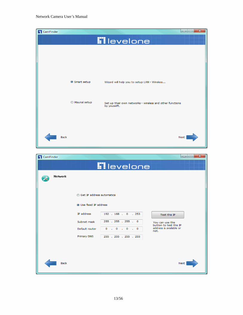
Network Camera Userrsquos Manual
1456
Network Camera Userrsquos Manual
1556
Bonjour program Safari browser supports Bonjour search program the will search for all family network devices on the same LAN
Network Camera Userrsquos Manual
1656
C2mylevel1com (Free DDNS service) 1 When you want to connect the network camera over Internet you can use the service ldquoC2mylevel1comrdquo The ldquoip-discoverycomrdquo is a free DDNS server for this camera Make sure that the router must start UPnP and DHCP server functions You can get the domain name which you wish very easily after registration In Network pagemdashDDNS settings of this camera you just input the host name you want and your e-mail address and click ldquoRegisterrdquo then you can have the hostname for this camera not longer than 20 seconds if the DDNS registration result is OK Then you can connect to this ip camera by httpXXXc2mylevel1com XXX the host name you type The HTTP port (get it automatically by c2mylevel1 server)
User password Default the password is last six number of the MAC To change ldquorootrdquo password at ldquoSecurity configurationrdquo can change the user password This ldquoUser passwordrdquo is entered in the c2mylevel1com Password Note You must set the ports between your router and camera manually if the registration is failed
Network Camera Userrsquos Manual
1756
Initial Access to the Network Camera
(1) For the initial access to the Network Camera in Windows the web browser may prompt for permission to install a new plug-in for the Network Camera This plug-in has been registered for certificate and is used to display the video in the browser
Users may click on to proceed
1 Click ldquoInstallrdquo and ldquoRunrdquo ActiveX controls 2 The video will be displayed
Network Camera Userrsquos Manual
1856
Primary userrsquos capability
Main Screen with Camera View The main page has three parts
1 Configuration functions The camera can be configured using these user interfaces
2 Connection control buttons These buttons provide the remote and local switching stream
3 Camera View What the camera sees Click the configuration in the bottom of left column to link to the configuration page
Configuration functions ldquoClient Settingsrdquo Clicking on this button links you to the client setting pages please check the following session for more details
ldquoConfigurationrdquo Please notes that only the administrator can access it ldquo Languagerdquo Click this button to choose a language for the user interface Language options are available in English traditional Chinese Simplified Chinese Japanese Spanish Portuguese French German Italiano
1
2
3
Network Camera Userrsquos Manual
1956
Camera view On the top of image shows the connecting type of the Network Camera and the current datetime
View capabilities
1 Click this button to capture and save still images The captured images will be
displayed in pop-up window Right-click the image and choose Save Picture As to save it in JPEG format
2 The button selection lets you open a digital zoom and to control the window to
enlarge a specified area in the camera view
3 Click this button to switch to full screen mode Press the ldquoEscrdquo key to switch back to normal mode
4 Click on this button freeze the video and playing when you click again
5 Click on this button stop video output
6 Use this functionyou can record video in your PC by browser directly The files
format will be in MP4
7 Click on this button adjust the audio volume amp Latency
8 Click on this button switch Mute OnOff
9 Click on this button to adjust the Function ldquo2-way audiordquo to be EnableDisable Enable this function request insert an external speaker The server can play sound from the client and receive sound from the environment and send to client
10 Click on this button to adjust the Microphone volume
Network Camera Userrsquos Manual
2056
11 Click on this button switch Microphone Mute OnOff Connection control buttons
1 ldquoConnectionrdquo User can choose Remote or Local mode for best connection quality Proposal Internet environment switch Remote mode
2 ldquoVideo Streamrdquo User can choose stream1 or stream2
Network Camera Userrsquos Manual
2156
Client Setting
1 ldquoIntranet Protocol Optionsrdquo Setting camera in intranet mode of protocol ldquoUDPrdquo Select use UDP protocol connect camera ldquoTCPrdquo Select use TCP protocol connect camera ldquoHTTPrdquo Select use HTTP protocol connect camera
2 ldquoInternet Protocol Optionsrdquo Setting camera in internet mode of protocol ldquoUDPrdquo Select use UDP protocol connect camera ldquoTCPrdquo Select use TCP protocol connect camera ldquoHTTPrdquo Select use HTTP protocol connect camera
3 ldquoRecording optionsrdquo Users can record live video as they are watching by
clicking start MP4 Recording on the main page Here you can specify the storage destination and file name
ldquoFolderrdquo Specify the storage destination for the recorded video files ldquoFile name prefixrdquo Enter the text that will be appended to the front of the video
file name ldquoAdd date and time suffix to file namerdquo Select this option to append the date
and time to the end of the file name
Network Camera Userrsquos Manual
2256
NOTEProtocol Options which allows choices on connection protocol between client and
server There are three protocols choices to optimize your usage ndash UDP TCP HTTP The UDP protocol allows for more real-time audio and video streams However some packets may be lost due to network burst traffic and images may be obscured The HTTP protocol allows for less packet loss and produces a more accurate video display The downside with this protocol is that the real-time effect is worse than that with the UDP protocol The TCP guarantees the complete delivery of streaming data and thus provides better video quality However the real-time effect is not as good as that of the UDP protocol If no special need is required UDP protocol is recommended Generally speaking the client choice will be in the order of UDP rarr HTTP After the Network Camera is connected successfully ldquoProtocol Optionrdquo will indicate the selected protocol The selected protocol will be recorded in the users PC and will be used for the next connection If the network environment is changed or the user wants to let the web browser to detect again manually select the UDP and TCP protocol save and return HOME to re-connect
Network Camera Userrsquos Manual
2356
Definitions in Configuration
Please note that only the Administrator can access the system configuration Each category in the left column will be explained on the following pages
System parameters
1 ldquoGeneral Settingrdquo
(1) ldquoHost namerdquo The text displays the title on the top of the main page
Firmware version
Network Camera Userrsquos Manual
2456
2 ldquoTime Settingrdquo (1) ldquoTime zonerdquo Choose a time zone from the down arrow
(2) ldquoDaylight savingrdquo For summertime It will be one hour ahead
(3) ldquoCurrent Timerdquo Network camera set the current time
(A) ldquoKeep current date and timerdquo Click on this to keep the current date and time of the Network Camera An internal real-time clock maintains the date and time even when the power of the system is turned off
(B) ldquoSync with computer timerdquo Synchronize the date and time in the Network Camera according to the local computer
(C) ldquoManualrdquo Adjust the date and time by the Administrator
(D) ldquoAdjust by NTP serverrdquo Synchronize the time according NTP server over the Internet whenever the Network Camera is switched on It fails if the assigned time-server cannot be found
(a) ldquoNTP serverrdquo Assign the IP address or domain name of the time-server Leaving the text box blank connects the Network Camera to the default time-servers
(b) ldquoUpdate intervalrdquo Select 0 ~ 23 hours update with the time on the NTP server
3 ldquoDI statusrdquo Please go to Application page for setting the DI
Network Camera Userrsquos Manual
2556
Security
Security setting The administrator account name is ldquorootrdquo which is permanent and can not be deleted If you want to add more accounts in the Manage User column please set a password for the ldquorootrdquo account first 1 ldquoChange root passwordrdquo Change the Administratorrsquos password by typing in the new password identically in both text boxes The typed entries will be displayed as asterisks for security purposes After pressing ldquofinishrdquo the web browser will ask the Administrator for the new password to access
2 ldquoManage privilegerdquo You can modify the manage privilege of operators or viewers Check or uncheck the item then click finish to enable the settings
3 ldquoManage userrdquo (1) ldquoAdd a new userrdquo Administrators can add up to 20 user accounts
(A) Input the new userrsquos name and password (B) Select the privilege level for the new user account Click Finish to enable the
setting
(2) ldquoDelete a userrdquo Select an existing user name Click Finish to enable the setting
Network Camera Userrsquos Manual
2656
(3) ldquoUpdate a existing userrdquo Select an existing user name Administrators can modify userrsquos password and privilege Click Finish to enable the setting
Access rights are sorted by user privilege (Administrator Operator and Viewer) Only administrators can access the Configuration page Operators cannot access the Configuration page but can use the URL Commands to get and set the value of parameters Viewers access only the main page for live viewing
Network
Any changes made on this page will restart the system in order to validate the changes Make sure every field is entered correctly before clicking on ldquofinishrdquo
Network Camera Userrsquos Manual
2756
Network Setting ldquoLANrdquo amp ldquoPPPoErdquo The default type is LAN Select PPPoE if using ADSL
1 LAN
The default status is Get IP address automatically This could be tedious to perform software installation whenever the Network Camera starts Therefore once the network is set especially for the IP address should be entered correctly Select Use fixed IP address then the Network Camera will skip installation The Network Camera will automatically restart and operate normally after a power outage You can run IP installer to check the IP address assigned to the Network Camera if the IP address is forgotten or you can use the UPnP function provided by the Network Camera (MS Windows XP provides UPnP function at My Network Place)
(1) ldquoGet IP address automaticallyrdquo (2) ldquoUse fixed IP addressrdquo
- ldquoIP addressrdquo This is necessary for network identification - ldquoSubnet maskrdquo This is used to determine if the destination is in the same subnet The default value is ldquo2552552550rdquo - ldquoDefault routerrdquo This is a gateway used to forward frames to destinations in a different subnet Invalid router setting will fail the transmission to destinations in different subnet - ldquoPrimary DNSrdquo The primary domain name server that translates hostnames into IP addresses - ldquoSecondary DNSrdquo Secondary domain name server backups the Primary DNS - ldquoEnable UPnP presentation amp port forwardingrdquo Enable UPnP ability - ldquoHttp portrdquo This can be typed besides the default Port 80 Once the port is changed the users must make sure the change for the connection is successful For instance when the Administrator changes the HTTP port of the Network Camera which IP address is 192168020 from 80 or 1025 to 65535 the users must type in the web browser ldquohttp1921680208080rdquo instead of ldquohttp192168020rdquo
- ldquoRTSP Portrdquo RTSP port can be typed besides the default Port 554 - ldquoRTP Portrdquo The RTP port can be typed besides the default Port 54
Note Please set Video RTP port in even number after default value port 54 Then
Video RTCP potAudio RTP portAudio RTCP port will automatically set the
values in ascending
- ldquoRTSP Streaming access namesrdquo The RTSP streaming currently supports video only audio only and audiovideo To use the audiovideo stream type the URL asldquortsp613012543liveNsdprdquo
2 PPPoE If using the PPPoE interface you should fill the following settings from ISP
(1) ldquoUser namerdquo The login name of PPPoE account (2) ldquoPasswordrdquo The password of PPPoE account (3) ldquoConfirm passwordrdquo Input password again for confirmation
Network Camera Userrsquos Manual
2856
DDNS Setting 1 ldquoEnable DDNSrdquo This option turns on the DDNS function
2 ldquoip-discoveryrdquo In the Register column fill in the Host name (xxxx ip-discovery) Email Key and Confirm Key then click Register After a host name has been successfully created a success message will be displayed in the DDNS Registration Result column and messaging E-mail
3 ldquo3rd party DDNSrdquo This is enable or disable 3rd party DDNS 4 ldquoProviderrdquo The provider list contains hosts that provide DDNS services Please connect to the service providerrsquos website to make sure the service charges
5 ldquoHost Namerdquo If the User wants to use DDNS service this field must be filled Please input the hostname that is registered in the DDNS server
6 ldquoUser namerdquo The Username or E-mail field is necessary for logging in the DDNS server or notify the User of the new IP address Note when this field is input as ldquoUser namerdquo the following field must be input as ldquoPasswordrdquo
7 ldquoPasswordrdquo Please input the password or key to get the DDNS service
8 ldquofinishrdquo Click on this button to save modify settings for the DDNS service
Network Camera Userrsquos Manual
2956
Access list
Access list setting 1 How to control access permission by verifying the client PCrsquos IP
address General Settings General Settings
Add a rule to configure an AllowedDenied list Click Add to add a rule
Network Camera Userrsquos Manual
3056
to AllowedDenied list There are three types of rules for user to set up ldquoSinglerdquo This rule allows the user to add an IP address to the AllowedDenied list For example
ldquoNetworkrdquo This rule allows the user to assign a network address and corresponding subnet mask to the AllowDeny List The IP address is written in the CIDR format For example
Network Camera Userrsquos Manual
3156
ldquoRangerdquo This rule allows the user to assign a range of IP addresses to the AllowDeny List This rule is only applied to IPv4 For example
Network Camera Userrsquos Manual
3256
Audio and Video setting
Network Camera Userrsquos Manual
3356
General Setting 1 ldquoColor moderdquo Select use color or monochrome video display
2 ldquoVideo orientationrdquo The orientation of video
(1) ldquoFliprdquo Vertically rotate the video
(2) ldquoMirrorrdquo Horizontally rotates the video
3 ldquoEnvironmentrdquo The orientation of video
(1) ldquoindoorrdquo This option is usually selected when the Network Camera is placed in indoor environments
(2) ldquooutdoorrdquo This option is usually selected when the Network Camera is placed in outdoor environments
4 ldquoPower freqrdquo Select 50 Hz or 60Hz power line frequency
The fluorescent light will flash according to the power line frequency that
depends on local utility Change the frequency setting to eliminate uncomfortable flash image when the light source is only fluorescent light
Video Setting 1 ldquoContrastrdquo Adjust the image contrast level which ranges from -5 to +5 The default value is set to 0
2 ldquoBrightnessrdquo Adjust the image brightness level which ranges from -5 to +5 The default value is set to 0
3 ldquoSaturationrdquo Adjust the image saturation level which ranges from -5 to +5 The default value is set to 0
4 ldquoSharpnessrdquo Adjust the image sharpness level which ranges from -5 to +5 The default value is set to 0
5 ldquoEVrdquo Exposure value represent the expected target value of the luminance of
the weighting result of AE windows in the image and its tolerance as offset
6 ldquoGainrdquo In the slide bar of Gain there are also two sliders which represent the
limitations to control the maximum gain value and the minimum one respectively Normally the minimum value is to 1x for better quality
Network Camera Userrsquos Manual
3456
Exposure setting Here it provides 3 mode Auto Backlight and Customized Auto and
Backlight modes are 2 default settings for general purpose and backlight scene
respectively
Customized mode relates to the grid window above can be pointed on for
interesting areas Within the mode Customized 1615 grids windows can be chosen to match wherewhat you are interested in Push down left-button of mouse and drag to draw the grids for interesting areas or push down right-button of mouse and drag to clean the grids for insignificant areas
ldquoTarget Luminance and Offsetrdquo
These two slide bar Target Luminance and Offset represent the expected
target value of the luminance of the weighting result of AE windows in the image and its tolerance as offset For example target luminance is set to 100 and target offset is set to 20 that means the average luminance of the AE window should be in the range from 80 to 120 (100plusmn(10 When the actual luminance does not meet this range the AE function will adjust shutter and gain to meet it as possible In some extreme cases it cannot reach the target because the environment is too bright or dark When the environment is not consistent eg with big moving objects and the offset is too narrow the AE will act more frequently that will cause the background of view inconsistent The offset value is recommended to set 15~25 of target luminance
Network Camera Userrsquos Manual
3556
ldquoGainrdquo
In the slide bar of Gain there are also two sliders which represent the limitations
to control the maximum gain value and the minimum one respectively Normally the minimum value is to 1x for better quality It is not allowed if the maximum slider and the minimum one are set to the same value without adjustable interval Besides the noise will be increased if the actual gain is too large When the max slider is dragged over sensors max gain the slide bar will become deep blue to represent it will apply Mozart 3s digital gain which extend the max gain for very low light
ldquoShutter Speedrdquo
There are 2 fields minimal and maximal time for the range of Shutter Speed
The precision of the parameter is 11000000 sec but it is NOT actual precision of the shutter speed of the sensor The actual precision of the shutter speed depends on each sensorrsquos specification Here it will be rounded to approach sensorrsquos effective exposure time To avoid flickering or banding phenomenon under fluorescent light the actual shutter speed will be locked at 1120 160
130 if Power Line Frequency is 60Hz or 1100 150 125 if Power Line
Frequency is 50Hz The setting of Power Line Frequency is on the sub-tab Video
and Audio The exposure may not be stable if the maximum value and the minimum one are set to the same value without adjustable interval Besides the frame rate will drop down if the actual shutter speed is too slow to meet expected frame rate
Noise reduction
Provides 2D and 3D features
Wide Dynamic Range Enable Wide Dynamic Range auto in different level to improve the exposure when both bright and dark areas simultaneously in the field of view of the camera The default is off
Infrared Led Setting 1 ldquoInfrared LED Controlrdquo IR led for Day and Night (Option) User can turn onoff the built-in IR led This function is very useful under low illumination environment
(1) ldquoAutordquo Select IR sensitivity from 0 to 4
(2) ldquoManualrdquo Turn onoff the IR led manually
- ldquoTurn onrdquo Turn on led - ldquoTurn offrdquo Turn off led
2 ldquoLow lux moderdquo The video quality will be improved when the camera is in low lux environment (1) ldquoDisable dark moderdquo Disable low lux mode
(2) ldquoEnable dark moderdquo Enable low lux mode
Network Camera Userrsquos Manual
3656
Video output Setting 1 ldquovideo outputrdquo Can switch between NTSC and PAL
Audio Setting 1 ldquoMuterdquo Audio mute
2 ldquoMicrophone rdquo External microphone
3 ldquoMic Volumerdquo Adjust microphone volume which ranges from 1 to 46
Video record
Schedule mode
(1) ldquoEvery dayrdquo EnableDisable every day application
(2) ldquoWeek dayrdquo EnableDisable week day application
(3)ldquoSelected dayrdquo EnableDisable selected day application
Schedule information
(1) Enter the ldquoStart timerdquo and ldquoStop timerdquo for day mode Note that the time format is [hhmm] and is expressed in 24-hour clock time By default the start and end time of day mode are set to 010000 and 235959
Network Camera Userrsquos Manual
3756
(2)ldquoSunrdquoldquoMonrdquoldquoTuerdquoldquoWedrdquoldquoThurdquoldquoFrirdquoldquoSatrdquo Select the days of the week to perform the application
(3) ldquoStart dayrdquo and ldquoStart timerdquo as the start timing the time ldquoEnd dayrdquo and ldquoEnd timerdquo as the end timing the time
(4) ldquoEnable cyclic recordingrdquo The cyclic recording function is enabled during the transaction stage when a storage space is full and the incoming streaming data is about to overwrite the previously saved videos
Record parameters (1)Source Select a stream for the recording source
(2)Recording interval Select the recording time interval
(3)Prefix file name You can setting the file name and enable or disable to add the date and time on file name
Response mode There are two choices of server types available NAS SD Card Select the item to display the detailed configuration options
(1)rdquoNASrdquo
--ldquoNAS server addressrdquo Enter IP address of the NAS server
--ldquoNAS shared directoryrdquo Enter the NAS shared directory path --ldquoWorkgrouprdquo Enter the NAS workgroup parameter --ldquoUser accountrdquo Enter the login name of the NAS account --ldquoUser passwordrdquo Enter the password of the NAS account Note Video record with the Application must be set to the same shared directory
path If you would like do detail recording settings or multi-channel recording please install bundled 64CH recording software in CD
Network Camera Userrsquos Manual
3856
Stream
Audio codec setting
(1)ldquoAudio codec typerdquo There are two choices of audio codec types
available rdquoAMRrdquo ldquoAACrdquo and rdquoG711rdquo
(2) ldquoBit raterdquo -- ldquoAMRrdquo The bit rates are selectable at the following rates
47505150590067007400795010200 and 12200
-- ldquoAACrdquo The bit rates are selectable at the following rates 8Kbps16Kbps 24Kbps and 32Kbps
-- ldquoG711rdquo pcmu and pcma
Video codec setting (1) ldquoSelect Streamrdquo The Network Camera supports ldquoStream 1rdquoand ldquoStream 2rdquo
(2) ldquoVideo codecrdquo The Network Camera supports three kind of video compression mode ldquoH264rdquo or ldquoMPEG4rdquo or ldquoMJPEGrdquo User can choose one of
Network Camera Userrsquos Manual
3956
these compression modes based on requirement or application
(3) ldquoVideo sizerdquo Click the down arrow to choose the quality of image (1920x1080 1280x1024 1280x800 640x480 320x240 176x144)
(4) ldquoConnection typerdquo User can select this button to choose the better video amp links quality (Internet mode or Intranet mode)
(5) ldquoFrame raterdquo This limits the maximal refresh frame rate per second Set the frame rate higher for a smoother video quality
(6) ldquoIntra frame periodrdquo Determine how often to plant an ldquoI framerdquo The shorter the duration the more likely you will get a better video quality but at the cost of higher network bandwidth consumption
(7) ldquoVideo Quality typerdquo Setting optimizes bandwidth utilization and video quality
-- ldquoConstant bit raterdquo User can adjust the video quality from 20 Kbps to 12 Mbps
-- ldquoFixed qualityrdquo user can select from lowest quality to get best quality according The ldquoQualityrdquo are selectable at the following rates From 1 to 20
Snapshot and time display setting Adjust the photo size specifications and choose whether to mark time on the video and photo
Network Camera Userrsquos Manual
4056
Application
Schedule mode
(1) ldquoEvery dayrdquo EnableDisable every day application
(2) ldquoWeek dayrdquo EnableDisable week day application
(3) ldquoSelected dayrdquo EnableDisable selected day application
Schedule information (1) Enter the ldquoStart timerdquo and ldquoStop timerdquo for day mode
Note that the time format is [hhmmss] and is expressed in 24-hour clock time By default the start and end time of day mode are set to 010000 and 235959
(2) ldquoSunrdquoldquoMonrdquoldquoTuerdquoldquoWedrdquoldquoThurdquoldquoFrirdquoldquoSatrdquo Select the days of the week to perform the application
(3) ldquoStart dayrdquo and ldquoStart timerdquo as the start timing the time ldquoEnd dayrdquo and ldquoEnd timerdquo as the end timing the time
Trigger mode
(1) ldquoVideo motion detectionrdquo EnableDisable video motion application (2) ldquoPeriodicallyrdquo This option allows the Network Camera to trigger
periodically for every other defined minute
Network Camera Userrsquos Manual
4156
(3) ldquoDigital inputrdquo This option allows the Network Camera to use an external digital input device or sensor as a trigger source Depending on your application there are many choices of digital input devices on the market which helps to detect changes in temperature vibration sound and light etc
parameters
(1) ldquoMotion parametersrdquo Higher sensitivity and small threshold will allow easier motion detection
(2) ldquoPeriod parametersrdquo This option allows the Network Camera to trigger periodically for every other defined seconds Up to 999 seconds are allowed
(3) ldquoDigital input parametersrdquo Select the digital input type and set trigger time
Media mode There are four choices of media types available ldquoSnapshotrdquo ldquoMessagerdquo ldquoRecord(Motion Detection only)rdquo and ldquoSystem logrdquo
Snapshot amp Record file setting You can setting the file name and enable or disable to add the date and time on file name Can setting the digital output duration seconds Response mode There are four choices of server types available Email FTP NAS and SD Card storage Select the item to display the detailed configuration options
(1)ldquoEmailrdquo -- ldquoEmail security moderdquo If your SMTP server requires a secure connection (SSL or TLS) check This server requires a secure connection (SSL or TLS) -- ldquoSender emailrdquo address Enter the email address of the sender -- ldquoRecipient emailrdquo address Enter the email address of the recipient
-- ldquoServer addressrdquo Enter the domain name or IP address of the email server
--ldquoUser namerdquo Enter the user name of the email account if necessary
--ldquoPasswordrdquo Enter the password of the email account if necessary
--ldquoServer portrdquo The default mail server port is set to 25 You can also manually set another port
(2)rdquoFTPrdquo -- ldquoServer addressrdquo Enter the domain name or IP address of the FTP server
-- ldquoServer portrdquo By default the FTP server port is set to 21
-- ldquoUser namerdquo Enter the login name of the FTP account
-- ldquoPasswordrdquo Enter the password of the FTP account
-- ldquoFTP folder namerdquo Enter the folder where the media file will be placed If the folder name does not exist the Network Camera will create one on the FTP server
(3)rdquoHTTP rdquo
-- ldquoURLrdquo Enter the URL of the HTTP server
-- ldquoUser accountrdquo Enter the user name if necessary -- ldquoUser passwordrdquo Enter the password if necessary
(4)rdquoNASrdquo --ldquoNAS server addressrdquo Enter IP address of the NAS server
--ldquoNAS shared directoryrdquo Enter the NAS shared directory path
Network Camera Userrsquos Manual
4256
--ldquoWorkgrouprdquo Enter the NAS workgroup parameter --ldquoUser accountrdquo Enter the login name of the NAS account --ldquoUser passwordrdquo Enter the password of the NAS account Note Video record with the Application must be set to the same shared directory
path If you would like do detail recording settings or multi-channel recording please install bundled 64CH recording software in CD
Network Camera Userrsquos Manual
4356
Storage
Manage the storage device
S torage Status Here show the storage device information
NAS server setting
1
2
3
Network Camera Userrsquos Manual
4456
(1) ldquoNAS Host namerdquo Choose and input the NAS Host name of this camera
(2) ldquoWorkgrouprdquo Input the name of Workgroup You can see the NAS Host name you input in the same workgroup with your PC Then you can connect to this device and download the files easily from SD card which is inserted to this camera
File operation Move the mouse over the file Press the mouse right button that Right-click menu is displayed You can delete files Move the mouse over the directory Press the mouse left button that the file structure expand Press the mouse right button that Right-click menu is displayed You can choose upload or delete files NOTEAllow the user to upload or delete files when the storage device is not write-
protected If the SD card canrsquot be detected please link to the following URL httpwwwsdcardorgconsumersformatter to download the ldquoSD Formatter Kitrdquo formatting your SD card
Network Camera Userrsquos Manual
4556
Syslog
The Network camera supports log the system messages on remote server The protocol is compliant to RFC 3164 If you have external Linux server with sys log service use ldquo-rrdquo option to turn on the facility for receiving log from remote machine Or you can use some software on Windows that is compliant to RFC 3164 An example is Kiwi Syslog Daemon Visit httpwwwkiwisyslogcomkiwi-syslog-daemon-overview Check ldquoSetuprdquo and ldquoEnablerdquo then input the ldquoIP addressrdquo and ldquoportrdquo number of the log server to enable the remote log facility In the ldquoCurrent logrdquo it displays the current system log file The content of the log provides useful information about configuration and connection after system boot- up
ldquofinishrdquo Click on this button to save modify settings
Network Camera Userrsquos Manual
4656
Status and Parameters
User can find a lot of information about the system such as ldquoUpnp port forwardingrdquo
ldquoTraversing NATrdquo ldquoPublic IPrdquo and so on User also can get the number of current viewer of the Network Camera here
Network Camera Userrsquos Manual
4756
Maintenance
1 ldquoReboot systemrdquo The ldquoRebootrdquo button will reboot the Network Camera Itrsquos useful while the Network Camera got problem 2 ldquoRestore systemrdquo Click on ldquoRestorerdquo button on the configuration page to restore the factory default settings Restore all settings to factory default except settings in ldquoNetwork type rdquo and ldquoRoot Passwordrdquo The system will restart and require the installer program to set up the network again
3 ldquoCalibraterdquo Recalibrate the auto focus position to the default range to recover the tolerance caused by some external forces 4 ldquoExportImport filerdquo -- Export setting backup file Click to export all parameters for the device and user-defined scripts
-- Upload setting backup file Click Browsehellip to upload a setting backup file Please note that the model and firmware version of the device should be the same as the setting backup file If you have set up a fixed IP or other special settings for your device it is not suggested to upload a settings backup file
4 ldquoUpgrade firmwarerdquo Select the firmware file and click upgrade button Please be aware that you should not turn off the power during updating the firmware and wait for finish message
Network Camera Userrsquos Manual
4856
Warning The upgrade firmware procedure cannot be interrupted If the power
andor network connection are broken during the procedure it might possibly cause serious damage to the Network Camera
Note When upgrade firmware please wait for 120~210 seconds and then you can connect to Network Camera again The system will restart and require the installer program to set up the network again
Network Camera Userrsquos Manual
4956
Appendix
A Troubleshooting amp Frequently Asked Questions Q1 Status led does not light up
A1 First make sure that「ConfigurationgtSystemgtTurn off the LED indicator」is disabled
If it is check the item and the led should light up Second if red led does not light up please check that the power adapter in the package is plugged correctly And last if green led does not light up please check that category 5 UTP cable is plugged correctly If the problem is still not solved please contact your dealer for further help
Q2 What kind of Ethernet cable is used by network camera
A2 The network Camera uses Category 5 UTP cable allowing 10 andor 100 Base-T networking
Q3 The Network Camera will be installed and work if a firewall exists on
the network
A3 There are two way to set up the IP camera at Internet (1) By UPnP Port Forwarding 1 Select an IP router It must support UPnP port forwarding and enable this function
first
2 Connect camera RJ45 cable to IP router and the router is also connected to Internet
3 Plug power cord to camera
4 Go to camera Network page Enable UPnP port forwarding
5 Check camera status we can see the ports had been successfully opened
Network Camera Userrsquos Manual
5056
6Type IP address8080 at browser Then you can see camera through Internet
7You can also type the ddns name at below label of camera on browser URL field For example you may type ah00001ip-discoverycom8080 (2) By Setting Port Forwarding Manually 1 Select a router Set the port forwarding as following
Network Camera Userrsquos Manual
5156
PS Port 80 is HTTP Port port 53 is stream port port 554 is RTSP port and port 443 is HTTPS port 2Go to camera Network page Disable UPnP port forwarding function
Network Camera Userrsquos Manual
5256
3 Type IP address at browser Then you can see camera through Internet
4 You can also type the ddns name at below label of camera on browser URL field For example you may type ah00001ip-discoverycom
Note The firewall software at PC may block the transfer of network camera Please remove or stop the kind software
Q4 How can I find the network camera in the local area network
A4 By using the IP Finder2 program or using UPnP to find it
Q5 IP Finder2 program cannot find Network Camera in the local area
network at first time
A5 Make sure the subnet of network camera is same as your PC If the local area network supports DHCP the camera is ldquoGet IP address automaticallyrdquo in the ldquoNetworkrdquo page default If the local area network does not support DHCP change your PC IP address to ldquo1921680xxxrdquo
Network Camera Userrsquos Manual
5356
Q6 How can I restore the network camera to default value
A6 Use a gem clip to press on the inside button Network camera begins to restore default value You can also press the button ldquoFactoryrdquo in ldquoMaintenancerdquo page to restore the default value
Q7 I cannot play the recorded video file
A7 Install the audio codec in the CD and use the Windows Media Player 10 or later to play the ASF or AVI file recorded by the network camera
Q8 Infrared led does not light up
A8 Check「ConfigurationgtAudio and VideogtInfrared LED Control」 is ldquoAutordquo or
ldquoManual》Turn onrdquo
Q9 The network camera cannot focus accurately
A9 (1) The lens is dirty or dust is attached Clean the lens with lens cleaner And then adjust the camera focus manually (2) The image may be out of focus If the object is too near move the object away from Network Camera
Q10 The cover of network camera is warm Is it normal
A10 Network camera is a precision device The internal material has the operational temperature and it is normal when user touch the cover feels warm It is recommended to put the network camera at aired place and not put at any other device
Q11 The process of upgrade firmware abort
A11 Contact your dealer for further help
Q12 Cannot access the login page and other web pages of Network
Network Camera Userrsquos Manual
5456
Camera from Internet Explorer
A12 bull May be due to the network cable Try correcting your network cable and configuration Test the network interface by connecting a local computer to the Network Camera via a crossover cable bull Make sure the Internet connection and setting is ok bull Make sure enter the IP address of Internet Explorer is correct If Network Camera has a dynamic address it may have changed since you last checked it bull Network congestion may prevent the web page appearing quickly Wait for a while The IP address and Subnet Mask of the PC and Network Camera must be in the same class of the private IP address on the LAN bull Make sure the http port used by the Network Camera default=80 is forward to the Network Camerarsquos private IP address bull The port number assigned in your Network Camera might not be available via Internet Check your ISP for available port bull The proxy server may prevent you from connecting directly to Network Camera set up not to use the proxy server bull Confirm that Default Gateway address is correct bull The router needs Port Forwarding feature Refer to your routers manual for details bull Packet Filtering of the router may prohibit access from an external network Refer to your routers manual for details bull Access Network Camera from the Internet with the global IP address of the router and port number of Network Camera bull Some routers reject the global IP address to access Network Camera on the same LAN Access with the private IP address and correct port number of Network Camera bull When you use DDNS you need to set Default Gateway and DNS server address bull If itrsquos not working after above procedure reset Network Camera to default setting and installed it again bull Maybe the IP Address of the Network Camera is already being used by another device or computer bull If the problem is not solved the Network Camera might be faulty Contact your dealer for further help
Network Camera Userrsquos Manual
5556
B Technical specifications
- System RAM 4G bit DDRⅢ
ROM 16MB Flash ROM
- Camera specification 127 inch color CMOS sensor Resolution 1920x1080 10LuxF20 AGC AWB AEC
- Infrared Led High power IR Leds 25~30 M visible AutoManual mode
- Lens 3X optical zoom lens auto iris auto focus f = 28~ 12mm F18 Fov(D) 136deg ~ 39deg
- Protocol TCPIP HTTPUDP SMTP FTP DDNS UPnP Telnet NTP PPPoE RTSP RTPRTCPDHCP and DNS
- Video Resolution Up to 30 frames at 176x144 Up to 30 frames at 320x240 Up to 30 frames at 640x480 Up to 30 frames at 1280x800 Up to 30 frames at 1280x1024 Up to 30 frames at 1920x1080
- Algorithm supported H264MPEG4MJPEG dual codec for streaming video JPEG for still image
- Audio AMRAACG711 External MIC input 2-way audio
- Physical 10 baseT100 baseT and 1000 baseT Fast
Ethernet auto negotiation
- Power Input 100-240VAC 5060Hz 07A Output 12VDC 15A Consumption Max 12 W Support 8023af compliant Power over Ethernet
- EMI amp Safety CE FCC
- Dimension Length 165mm Diameter 75mm
- Operating Environment Temperature -20 ~ 50
Humidity 85 RH
- Weight NET 600g With bracket 800g
Network Camera Userrsquos Manual
5656
Notification of Compliance Appendix C
Europe - EU Declaration of Conformity
For complete DoC please visit httpgloballevel1comdownloadsphpaction=init
GPL License Agreement GPL may be included in this product to view the GPL license agreement goes to httpdownloadlevel1comlevel1gplGPLpdf For GNU General Public License (GPL) related information please visit httpgloballevel1comdownloadsphpaction=init
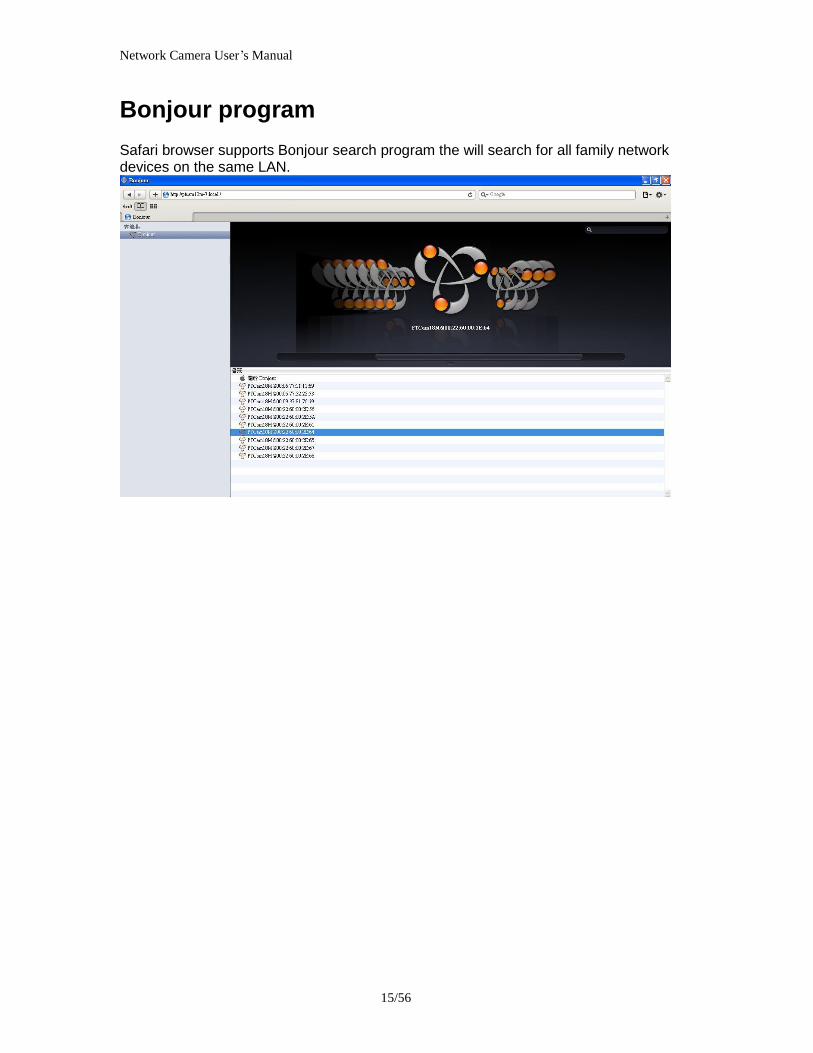
Network Camera Userrsquos Manual
2056
11 Click on this button switch Microphone Mute OnOff Connection control buttons
1 ldquoConnectionrdquo User can choose Remote or Local mode for best connection quality Proposal Internet environment switch Remote mode
2 ldquoVideo Streamrdquo User can choose stream1 or stream2
Network Camera Userrsquos Manual
2156
Client Setting
1 ldquoIntranet Protocol Optionsrdquo Setting camera in intranet mode of protocol ldquoUDPrdquo Select use UDP protocol connect camera ldquoTCPrdquo Select use TCP protocol connect camera ldquoHTTPrdquo Select use HTTP protocol connect camera
2 ldquoInternet Protocol Optionsrdquo Setting camera in internet mode of protocol ldquoUDPrdquo Select use UDP protocol connect camera ldquoTCPrdquo Select use TCP protocol connect camera ldquoHTTPrdquo Select use HTTP protocol connect camera
3 ldquoRecording optionsrdquo Users can record live video as they are watching by
clicking start MP4 Recording on the main page Here you can specify the storage destination and file name
ldquoFolderrdquo Specify the storage destination for the recorded video files ldquoFile name prefixrdquo Enter the text that will be appended to the front of the video
file name ldquoAdd date and time suffix to file namerdquo Select this option to append the date
and time to the end of the file name
Network Camera Userrsquos Manual
2256
NOTEProtocol Options which allows choices on connection protocol between client and
server There are three protocols choices to optimize your usage ndash UDP TCP HTTP The UDP protocol allows for more real-time audio and video streams However some packets may be lost due to network burst traffic and images may be obscured The HTTP protocol allows for less packet loss and produces a more accurate video display The downside with this protocol is that the real-time effect is worse than that with the UDP protocol The TCP guarantees the complete delivery of streaming data and thus provides better video quality However the real-time effect is not as good as that of the UDP protocol If no special need is required UDP protocol is recommended Generally speaking the client choice will be in the order of UDP rarr HTTP After the Network Camera is connected successfully ldquoProtocol Optionrdquo will indicate the selected protocol The selected protocol will be recorded in the users PC and will be used for the next connection If the network environment is changed or the user wants to let the web browser to detect again manually select the UDP and TCP protocol save and return HOME to re-connect
Network Camera Userrsquos Manual
2356
Definitions in Configuration
Please note that only the Administrator can access the system configuration Each category in the left column will be explained on the following pages
System parameters
1 ldquoGeneral Settingrdquo
(1) ldquoHost namerdquo The text displays the title on the top of the main page
Firmware version
Network Camera Userrsquos Manual
2456
2 ldquoTime Settingrdquo (1) ldquoTime zonerdquo Choose a time zone from the down arrow
(2) ldquoDaylight savingrdquo For summertime It will be one hour ahead
(3) ldquoCurrent Timerdquo Network camera set the current time
(A) ldquoKeep current date and timerdquo Click on this to keep the current date and time of the Network Camera An internal real-time clock maintains the date and time even when the power of the system is turned off
(B) ldquoSync with computer timerdquo Synchronize the date and time in the Network Camera according to the local computer
(C) ldquoManualrdquo Adjust the date and time by the Administrator
(D) ldquoAdjust by NTP serverrdquo Synchronize the time according NTP server over the Internet whenever the Network Camera is switched on It fails if the assigned time-server cannot be found
(a) ldquoNTP serverrdquo Assign the IP address or domain name of the time-server Leaving the text box blank connects the Network Camera to the default time-servers
(b) ldquoUpdate intervalrdquo Select 0 ~ 23 hours update with the time on the NTP server
3 ldquoDI statusrdquo Please go to Application page for setting the DI
Network Camera Userrsquos Manual
2556
Security
Security setting The administrator account name is ldquorootrdquo which is permanent and can not be deleted If you want to add more accounts in the Manage User column please set a password for the ldquorootrdquo account first 1 ldquoChange root passwordrdquo Change the Administratorrsquos password by typing in the new password identically in both text boxes The typed entries will be displayed as asterisks for security purposes After pressing ldquofinishrdquo the web browser will ask the Administrator for the new password to access
2 ldquoManage privilegerdquo You can modify the manage privilege of operators or viewers Check or uncheck the item then click finish to enable the settings
3 ldquoManage userrdquo (1) ldquoAdd a new userrdquo Administrators can add up to 20 user accounts
(A) Input the new userrsquos name and password (B) Select the privilege level for the new user account Click Finish to enable the
setting
(2) ldquoDelete a userrdquo Select an existing user name Click Finish to enable the setting
Network Camera Userrsquos Manual
2656
(3) ldquoUpdate a existing userrdquo Select an existing user name Administrators can modify userrsquos password and privilege Click Finish to enable the setting
Access rights are sorted by user privilege (Administrator Operator and Viewer) Only administrators can access the Configuration page Operators cannot access the Configuration page but can use the URL Commands to get and set the value of parameters Viewers access only the main page for live viewing
Network
Any changes made on this page will restart the system in order to validate the changes Make sure every field is entered correctly before clicking on ldquofinishrdquo
Network Camera Userrsquos Manual
2756
Network Setting ldquoLANrdquo amp ldquoPPPoErdquo The default type is LAN Select PPPoE if using ADSL
1 LAN
The default status is Get IP address automatically This could be tedious to perform software installation whenever the Network Camera starts Therefore once the network is set especially for the IP address should be entered correctly Select Use fixed IP address then the Network Camera will skip installation The Network Camera will automatically restart and operate normally after a power outage You can run IP installer to check the IP address assigned to the Network Camera if the IP address is forgotten or you can use the UPnP function provided by the Network Camera (MS Windows XP provides UPnP function at My Network Place)
(1) ldquoGet IP address automaticallyrdquo (2) ldquoUse fixed IP addressrdquo
- ldquoIP addressrdquo This is necessary for network identification - ldquoSubnet maskrdquo This is used to determine if the destination is in the same subnet The default value is ldquo2552552550rdquo - ldquoDefault routerrdquo This is a gateway used to forward frames to destinations in a different subnet Invalid router setting will fail the transmission to destinations in different subnet - ldquoPrimary DNSrdquo The primary domain name server that translates hostnames into IP addresses - ldquoSecondary DNSrdquo Secondary domain name server backups the Primary DNS - ldquoEnable UPnP presentation amp port forwardingrdquo Enable UPnP ability - ldquoHttp portrdquo This can be typed besides the default Port 80 Once the port is changed the users must make sure the change for the connection is successful For instance when the Administrator changes the HTTP port of the Network Camera which IP address is 192168020 from 80 or 1025 to 65535 the users must type in the web browser ldquohttp1921680208080rdquo instead of ldquohttp192168020rdquo
- ldquoRTSP Portrdquo RTSP port can be typed besides the default Port 554 - ldquoRTP Portrdquo The RTP port can be typed besides the default Port 54
Note Please set Video RTP port in even number after default value port 54 Then
Video RTCP potAudio RTP portAudio RTCP port will automatically set the
values in ascending
- ldquoRTSP Streaming access namesrdquo The RTSP streaming currently supports video only audio only and audiovideo To use the audiovideo stream type the URL asldquortsp613012543liveNsdprdquo
2 PPPoE If using the PPPoE interface you should fill the following settings from ISP
(1) ldquoUser namerdquo The login name of PPPoE account (2) ldquoPasswordrdquo The password of PPPoE account (3) ldquoConfirm passwordrdquo Input password again for confirmation
Network Camera Userrsquos Manual
2856
DDNS Setting 1 ldquoEnable DDNSrdquo This option turns on the DDNS function
2 ldquoip-discoveryrdquo In the Register column fill in the Host name (xxxx ip-discovery) Email Key and Confirm Key then click Register After a host name has been successfully created a success message will be displayed in the DDNS Registration Result column and messaging E-mail
3 ldquo3rd party DDNSrdquo This is enable or disable 3rd party DDNS 4 ldquoProviderrdquo The provider list contains hosts that provide DDNS services Please connect to the service providerrsquos website to make sure the service charges
5 ldquoHost Namerdquo If the User wants to use DDNS service this field must be filled Please input the hostname that is registered in the DDNS server
6 ldquoUser namerdquo The Username or E-mail field is necessary for logging in the DDNS server or notify the User of the new IP address Note when this field is input as ldquoUser namerdquo the following field must be input as ldquoPasswordrdquo
7 ldquoPasswordrdquo Please input the password or key to get the DDNS service
8 ldquofinishrdquo Click on this button to save modify settings for the DDNS service
Network Camera Userrsquos Manual
2956
Access list
Access list setting 1 How to control access permission by verifying the client PCrsquos IP
address General Settings General Settings
Add a rule to configure an AllowedDenied list Click Add to add a rule
Network Camera Userrsquos Manual
3056
to AllowedDenied list There are three types of rules for user to set up ldquoSinglerdquo This rule allows the user to add an IP address to the AllowedDenied list For example
ldquoNetworkrdquo This rule allows the user to assign a network address and corresponding subnet mask to the AllowDeny List The IP address is written in the CIDR format For example
Network Camera Userrsquos Manual
3156
ldquoRangerdquo This rule allows the user to assign a range of IP addresses to the AllowDeny List This rule is only applied to IPv4 For example
Network Camera Userrsquos Manual
3256
Audio and Video setting
Network Camera Userrsquos Manual
3356
General Setting 1 ldquoColor moderdquo Select use color or monochrome video display
2 ldquoVideo orientationrdquo The orientation of video
(1) ldquoFliprdquo Vertically rotate the video
(2) ldquoMirrorrdquo Horizontally rotates the video
3 ldquoEnvironmentrdquo The orientation of video
(1) ldquoindoorrdquo This option is usually selected when the Network Camera is placed in indoor environments
(2) ldquooutdoorrdquo This option is usually selected when the Network Camera is placed in outdoor environments
4 ldquoPower freqrdquo Select 50 Hz or 60Hz power line frequency
The fluorescent light will flash according to the power line frequency that
depends on local utility Change the frequency setting to eliminate uncomfortable flash image when the light source is only fluorescent light
Video Setting 1 ldquoContrastrdquo Adjust the image contrast level which ranges from -5 to +5 The default value is set to 0
2 ldquoBrightnessrdquo Adjust the image brightness level which ranges from -5 to +5 The default value is set to 0
3 ldquoSaturationrdquo Adjust the image saturation level which ranges from -5 to +5 The default value is set to 0
4 ldquoSharpnessrdquo Adjust the image sharpness level which ranges from -5 to +5 The default value is set to 0
5 ldquoEVrdquo Exposure value represent the expected target value of the luminance of
the weighting result of AE windows in the image and its tolerance as offset
6 ldquoGainrdquo In the slide bar of Gain there are also two sliders which represent the
limitations to control the maximum gain value and the minimum one respectively Normally the minimum value is to 1x for better quality
Network Camera Userrsquos Manual
3456
Exposure setting Here it provides 3 mode Auto Backlight and Customized Auto and
Backlight modes are 2 default settings for general purpose and backlight scene
respectively
Customized mode relates to the grid window above can be pointed on for
interesting areas Within the mode Customized 1615 grids windows can be chosen to match wherewhat you are interested in Push down left-button of mouse and drag to draw the grids for interesting areas or push down right-button of mouse and drag to clean the grids for insignificant areas
ldquoTarget Luminance and Offsetrdquo
These two slide bar Target Luminance and Offset represent the expected
target value of the luminance of the weighting result of AE windows in the image and its tolerance as offset For example target luminance is set to 100 and target offset is set to 20 that means the average luminance of the AE window should be in the range from 80 to 120 (100plusmn(10 When the actual luminance does not meet this range the AE function will adjust shutter and gain to meet it as possible In some extreme cases it cannot reach the target because the environment is too bright or dark When the environment is not consistent eg with big moving objects and the offset is too narrow the AE will act more frequently that will cause the background of view inconsistent The offset value is recommended to set 15~25 of target luminance
Network Camera Userrsquos Manual
3556
ldquoGainrdquo
In the slide bar of Gain there are also two sliders which represent the limitations
to control the maximum gain value and the minimum one respectively Normally the minimum value is to 1x for better quality It is not allowed if the maximum slider and the minimum one are set to the same value without adjustable interval Besides the noise will be increased if the actual gain is too large When the max slider is dragged over sensors max gain the slide bar will become deep blue to represent it will apply Mozart 3s digital gain which extend the max gain for very low light
ldquoShutter Speedrdquo
There are 2 fields minimal and maximal time for the range of Shutter Speed
The precision of the parameter is 11000000 sec but it is NOT actual precision of the shutter speed of the sensor The actual precision of the shutter speed depends on each sensorrsquos specification Here it will be rounded to approach sensorrsquos effective exposure time To avoid flickering or banding phenomenon under fluorescent light the actual shutter speed will be locked at 1120 160
130 if Power Line Frequency is 60Hz or 1100 150 125 if Power Line
Frequency is 50Hz The setting of Power Line Frequency is on the sub-tab Video
and Audio The exposure may not be stable if the maximum value and the minimum one are set to the same value without adjustable interval Besides the frame rate will drop down if the actual shutter speed is too slow to meet expected frame rate
Noise reduction
Provides 2D and 3D features
Wide Dynamic Range Enable Wide Dynamic Range auto in different level to improve the exposure when both bright and dark areas simultaneously in the field of view of the camera The default is off
Infrared Led Setting 1 ldquoInfrared LED Controlrdquo IR led for Day and Night (Option) User can turn onoff the built-in IR led This function is very useful under low illumination environment
(1) ldquoAutordquo Select IR sensitivity from 0 to 4
(2) ldquoManualrdquo Turn onoff the IR led manually
- ldquoTurn onrdquo Turn on led - ldquoTurn offrdquo Turn off led
2 ldquoLow lux moderdquo The video quality will be improved when the camera is in low lux environment (1) ldquoDisable dark moderdquo Disable low lux mode
(2) ldquoEnable dark moderdquo Enable low lux mode
Network Camera Userrsquos Manual
3656
Video output Setting 1 ldquovideo outputrdquo Can switch between NTSC and PAL
Audio Setting 1 ldquoMuterdquo Audio mute
2 ldquoMicrophone rdquo External microphone
3 ldquoMic Volumerdquo Adjust microphone volume which ranges from 1 to 46
Video record
Schedule mode
(1) ldquoEvery dayrdquo EnableDisable every day application
(2) ldquoWeek dayrdquo EnableDisable week day application
(3)ldquoSelected dayrdquo EnableDisable selected day application
Schedule information
(1) Enter the ldquoStart timerdquo and ldquoStop timerdquo for day mode Note that the time format is [hhmm] and is expressed in 24-hour clock time By default the start and end time of day mode are set to 010000 and 235959
Network Camera Userrsquos Manual
3756
(2)ldquoSunrdquoldquoMonrdquoldquoTuerdquoldquoWedrdquoldquoThurdquoldquoFrirdquoldquoSatrdquo Select the days of the week to perform the application
(3) ldquoStart dayrdquo and ldquoStart timerdquo as the start timing the time ldquoEnd dayrdquo and ldquoEnd timerdquo as the end timing the time
(4) ldquoEnable cyclic recordingrdquo The cyclic recording function is enabled during the transaction stage when a storage space is full and the incoming streaming data is about to overwrite the previously saved videos
Record parameters (1)Source Select a stream for the recording source
(2)Recording interval Select the recording time interval
(3)Prefix file name You can setting the file name and enable or disable to add the date and time on file name
Response mode There are two choices of server types available NAS SD Card Select the item to display the detailed configuration options
(1)rdquoNASrdquo
--ldquoNAS server addressrdquo Enter IP address of the NAS server
--ldquoNAS shared directoryrdquo Enter the NAS shared directory path --ldquoWorkgrouprdquo Enter the NAS workgroup parameter --ldquoUser accountrdquo Enter the login name of the NAS account --ldquoUser passwordrdquo Enter the password of the NAS account Note Video record with the Application must be set to the same shared directory
path If you would like do detail recording settings or multi-channel recording please install bundled 64CH recording software in CD
Network Camera Userrsquos Manual
3856
Stream
Audio codec setting
(1)ldquoAudio codec typerdquo There are two choices of audio codec types
available rdquoAMRrdquo ldquoAACrdquo and rdquoG711rdquo
(2) ldquoBit raterdquo -- ldquoAMRrdquo The bit rates are selectable at the following rates
47505150590067007400795010200 and 12200
-- ldquoAACrdquo The bit rates are selectable at the following rates 8Kbps16Kbps 24Kbps and 32Kbps
-- ldquoG711rdquo pcmu and pcma
Video codec setting (1) ldquoSelect Streamrdquo The Network Camera supports ldquoStream 1rdquoand ldquoStream 2rdquo
(2) ldquoVideo codecrdquo The Network Camera supports three kind of video compression mode ldquoH264rdquo or ldquoMPEG4rdquo or ldquoMJPEGrdquo User can choose one of
Network Camera Userrsquos Manual
3956
these compression modes based on requirement or application
(3) ldquoVideo sizerdquo Click the down arrow to choose the quality of image (1920x1080 1280x1024 1280x800 640x480 320x240 176x144)
(4) ldquoConnection typerdquo User can select this button to choose the better video amp links quality (Internet mode or Intranet mode)
(5) ldquoFrame raterdquo This limits the maximal refresh frame rate per second Set the frame rate higher for a smoother video quality
(6) ldquoIntra frame periodrdquo Determine how often to plant an ldquoI framerdquo The shorter the duration the more likely you will get a better video quality but at the cost of higher network bandwidth consumption
(7) ldquoVideo Quality typerdquo Setting optimizes bandwidth utilization and video quality
-- ldquoConstant bit raterdquo User can adjust the video quality from 20 Kbps to 12 Mbps
-- ldquoFixed qualityrdquo user can select from lowest quality to get best quality according The ldquoQualityrdquo are selectable at the following rates From 1 to 20
Snapshot and time display setting Adjust the photo size specifications and choose whether to mark time on the video and photo
Network Camera Userrsquos Manual
4056
Application
Schedule mode
(1) ldquoEvery dayrdquo EnableDisable every day application
(2) ldquoWeek dayrdquo EnableDisable week day application
(3) ldquoSelected dayrdquo EnableDisable selected day application
Schedule information (1) Enter the ldquoStart timerdquo and ldquoStop timerdquo for day mode
Note that the time format is [hhmmss] and is expressed in 24-hour clock time By default the start and end time of day mode are set to 010000 and 235959
(2) ldquoSunrdquoldquoMonrdquoldquoTuerdquoldquoWedrdquoldquoThurdquoldquoFrirdquoldquoSatrdquo Select the days of the week to perform the application
(3) ldquoStart dayrdquo and ldquoStart timerdquo as the start timing the time ldquoEnd dayrdquo and ldquoEnd timerdquo as the end timing the time
Trigger mode
(1) ldquoVideo motion detectionrdquo EnableDisable video motion application (2) ldquoPeriodicallyrdquo This option allows the Network Camera to trigger
periodically for every other defined minute
Network Camera Userrsquos Manual
4156
(3) ldquoDigital inputrdquo This option allows the Network Camera to use an external digital input device or sensor as a trigger source Depending on your application there are many choices of digital input devices on the market which helps to detect changes in temperature vibration sound and light etc
parameters
(1) ldquoMotion parametersrdquo Higher sensitivity and small threshold will allow easier motion detection
(2) ldquoPeriod parametersrdquo This option allows the Network Camera to trigger periodically for every other defined seconds Up to 999 seconds are allowed
(3) ldquoDigital input parametersrdquo Select the digital input type and set trigger time
Media mode There are four choices of media types available ldquoSnapshotrdquo ldquoMessagerdquo ldquoRecord(Motion Detection only)rdquo and ldquoSystem logrdquo
Snapshot amp Record file setting You can setting the file name and enable or disable to add the date and time on file name Can setting the digital output duration seconds Response mode There are four choices of server types available Email FTP NAS and SD Card storage Select the item to display the detailed configuration options
(1)ldquoEmailrdquo -- ldquoEmail security moderdquo If your SMTP server requires a secure connection (SSL or TLS) check This server requires a secure connection (SSL or TLS) -- ldquoSender emailrdquo address Enter the email address of the sender -- ldquoRecipient emailrdquo address Enter the email address of the recipient
-- ldquoServer addressrdquo Enter the domain name or IP address of the email server
--ldquoUser namerdquo Enter the user name of the email account if necessary
--ldquoPasswordrdquo Enter the password of the email account if necessary
--ldquoServer portrdquo The default mail server port is set to 25 You can also manually set another port
(2)rdquoFTPrdquo -- ldquoServer addressrdquo Enter the domain name or IP address of the FTP server
-- ldquoServer portrdquo By default the FTP server port is set to 21
-- ldquoUser namerdquo Enter the login name of the FTP account
-- ldquoPasswordrdquo Enter the password of the FTP account
-- ldquoFTP folder namerdquo Enter the folder where the media file will be placed If the folder name does not exist the Network Camera will create one on the FTP server
(3)rdquoHTTP rdquo
-- ldquoURLrdquo Enter the URL of the HTTP server
-- ldquoUser accountrdquo Enter the user name if necessary -- ldquoUser passwordrdquo Enter the password if necessary
(4)rdquoNASrdquo --ldquoNAS server addressrdquo Enter IP address of the NAS server
--ldquoNAS shared directoryrdquo Enter the NAS shared directory path
Network Camera Userrsquos Manual
4256
--ldquoWorkgrouprdquo Enter the NAS workgroup parameter --ldquoUser accountrdquo Enter the login name of the NAS account --ldquoUser passwordrdquo Enter the password of the NAS account Note Video record with the Application must be set to the same shared directory
path If you would like do detail recording settings or multi-channel recording please install bundled 64CH recording software in CD
Network Camera Userrsquos Manual
4356
Storage
Manage the storage device
S torage Status Here show the storage device information
NAS server setting
1
2
3
Network Camera Userrsquos Manual
4456
(1) ldquoNAS Host namerdquo Choose and input the NAS Host name of this camera
(2) ldquoWorkgrouprdquo Input the name of Workgroup You can see the NAS Host name you input in the same workgroup with your PC Then you can connect to this device and download the files easily from SD card which is inserted to this camera
File operation Move the mouse over the file Press the mouse right button that Right-click menu is displayed You can delete files Move the mouse over the directory Press the mouse left button that the file structure expand Press the mouse right button that Right-click menu is displayed You can choose upload or delete files NOTEAllow the user to upload or delete files when the storage device is not write-
protected If the SD card canrsquot be detected please link to the following URL httpwwwsdcardorgconsumersformatter to download the ldquoSD Formatter Kitrdquo formatting your SD card
Network Camera Userrsquos Manual
4556
Syslog
The Network camera supports log the system messages on remote server The protocol is compliant to RFC 3164 If you have external Linux server with sys log service use ldquo-rrdquo option to turn on the facility for receiving log from remote machine Or you can use some software on Windows that is compliant to RFC 3164 An example is Kiwi Syslog Daemon Visit httpwwwkiwisyslogcomkiwi-syslog-daemon-overview Check ldquoSetuprdquo and ldquoEnablerdquo then input the ldquoIP addressrdquo and ldquoportrdquo number of the log server to enable the remote log facility In the ldquoCurrent logrdquo it displays the current system log file The content of the log provides useful information about configuration and connection after system boot- up
ldquofinishrdquo Click on this button to save modify settings
Network Camera Userrsquos Manual
4656
Status and Parameters
User can find a lot of information about the system such as ldquoUpnp port forwardingrdquo
ldquoTraversing NATrdquo ldquoPublic IPrdquo and so on User also can get the number of current viewer of the Network Camera here
Network Camera Userrsquos Manual
4756
Maintenance
1 ldquoReboot systemrdquo The ldquoRebootrdquo button will reboot the Network Camera Itrsquos useful while the Network Camera got problem 2 ldquoRestore systemrdquo Click on ldquoRestorerdquo button on the configuration page to restore the factory default settings Restore all settings to factory default except settings in ldquoNetwork type rdquo and ldquoRoot Passwordrdquo The system will restart and require the installer program to set up the network again
3 ldquoCalibraterdquo Recalibrate the auto focus position to the default range to recover the tolerance caused by some external forces 4 ldquoExportImport filerdquo -- Export setting backup file Click to export all parameters for the device and user-defined scripts
-- Upload setting backup file Click Browsehellip to upload a setting backup file Please note that the model and firmware version of the device should be the same as the setting backup file If you have set up a fixed IP or other special settings for your device it is not suggested to upload a settings backup file
4 ldquoUpgrade firmwarerdquo Select the firmware file and click upgrade button Please be aware that you should not turn off the power during updating the firmware and wait for finish message
Network Camera Userrsquos Manual
4856
Warning The upgrade firmware procedure cannot be interrupted If the power
andor network connection are broken during the procedure it might possibly cause serious damage to the Network Camera
Note When upgrade firmware please wait for 120~210 seconds and then you can connect to Network Camera again The system will restart and require the installer program to set up the network again
Network Camera Userrsquos Manual
4956
Appendix
A Troubleshooting amp Frequently Asked Questions Q1 Status led does not light up
A1 First make sure that「ConfigurationgtSystemgtTurn off the LED indicator」is disabled
If it is check the item and the led should light up Second if red led does not light up please check that the power adapter in the package is plugged correctly And last if green led does not light up please check that category 5 UTP cable is plugged correctly If the problem is still not solved please contact your dealer for further help
Q2 What kind of Ethernet cable is used by network camera
A2 The network Camera uses Category 5 UTP cable allowing 10 andor 100 Base-T networking
Q3 The Network Camera will be installed and work if a firewall exists on
the network
A3 There are two way to set up the IP camera at Internet (1) By UPnP Port Forwarding 1 Select an IP router It must support UPnP port forwarding and enable this function
first
2 Connect camera RJ45 cable to IP router and the router is also connected to Internet
3 Plug power cord to camera
4 Go to camera Network page Enable UPnP port forwarding
5 Check camera status we can see the ports had been successfully opened
Network Camera Userrsquos Manual
5056
6Type IP address8080 at browser Then you can see camera through Internet
7You can also type the ddns name at below label of camera on browser URL field For example you may type ah00001ip-discoverycom8080 (2) By Setting Port Forwarding Manually 1 Select a router Set the port forwarding as following
Network Camera Userrsquos Manual
5156
PS Port 80 is HTTP Port port 53 is stream port port 554 is RTSP port and port 443 is HTTPS port 2Go to camera Network page Disable UPnP port forwarding function
Network Camera Userrsquos Manual
5256
3 Type IP address at browser Then you can see camera through Internet
4 You can also type the ddns name at below label of camera on browser URL field For example you may type ah00001ip-discoverycom
Note The firewall software at PC may block the transfer of network camera Please remove or stop the kind software
Q4 How can I find the network camera in the local area network
A4 By using the IP Finder2 program or using UPnP to find it
Q5 IP Finder2 program cannot find Network Camera in the local area
network at first time
A5 Make sure the subnet of network camera is same as your PC If the local area network supports DHCP the camera is ldquoGet IP address automaticallyrdquo in the ldquoNetworkrdquo page default If the local area network does not support DHCP change your PC IP address to ldquo1921680xxxrdquo
Network Camera Userrsquos Manual
5356
Q6 How can I restore the network camera to default value
A6 Use a gem clip to press on the inside button Network camera begins to restore default value You can also press the button ldquoFactoryrdquo in ldquoMaintenancerdquo page to restore the default value
Q7 I cannot play the recorded video file
A7 Install the audio codec in the CD and use the Windows Media Player 10 or later to play the ASF or AVI file recorded by the network camera
Q8 Infrared led does not light up
A8 Check「ConfigurationgtAudio and VideogtInfrared LED Control」 is ldquoAutordquo or
ldquoManual》Turn onrdquo
Q9 The network camera cannot focus accurately
A9 (1) The lens is dirty or dust is attached Clean the lens with lens cleaner And then adjust the camera focus manually (2) The image may be out of focus If the object is too near move the object away from Network Camera
Q10 The cover of network camera is warm Is it normal
A10 Network camera is a precision device The internal material has the operational temperature and it is normal when user touch the cover feels warm It is recommended to put the network camera at aired place and not put at any other device
Q11 The process of upgrade firmware abort
A11 Contact your dealer for further help
Q12 Cannot access the login page and other web pages of Network
Network Camera Userrsquos Manual
5456
Camera from Internet Explorer
A12 bull May be due to the network cable Try correcting your network cable and configuration Test the network interface by connecting a local computer to the Network Camera via a crossover cable bull Make sure the Internet connection and setting is ok bull Make sure enter the IP address of Internet Explorer is correct If Network Camera has a dynamic address it may have changed since you last checked it bull Network congestion may prevent the web page appearing quickly Wait for a while The IP address and Subnet Mask of the PC and Network Camera must be in the same class of the private IP address on the LAN bull Make sure the http port used by the Network Camera default=80 is forward to the Network Camerarsquos private IP address bull The port number assigned in your Network Camera might not be available via Internet Check your ISP for available port bull The proxy server may prevent you from connecting directly to Network Camera set up not to use the proxy server bull Confirm that Default Gateway address is correct bull The router needs Port Forwarding feature Refer to your routers manual for details bull Packet Filtering of the router may prohibit access from an external network Refer to your routers manual for details bull Access Network Camera from the Internet with the global IP address of the router and port number of Network Camera bull Some routers reject the global IP address to access Network Camera on the same LAN Access with the private IP address and correct port number of Network Camera bull When you use DDNS you need to set Default Gateway and DNS server address bull If itrsquos not working after above procedure reset Network Camera to default setting and installed it again bull Maybe the IP Address of the Network Camera is already being used by another device or computer bull If the problem is not solved the Network Camera might be faulty Contact your dealer for further help
Network Camera Userrsquos Manual
5556
B Technical specifications
- System RAM 4G bit DDRⅢ
ROM 16MB Flash ROM
- Camera specification 127 inch color CMOS sensor Resolution 1920x1080 10LuxF20 AGC AWB AEC
- Infrared Led High power IR Leds 25~30 M visible AutoManual mode
- Lens 3X optical zoom lens auto iris auto focus f = 28~ 12mm F18 Fov(D) 136deg ~ 39deg
- Protocol TCPIP HTTPUDP SMTP FTP DDNS UPnP Telnet NTP PPPoE RTSP RTPRTCPDHCP and DNS
- Video Resolution Up to 30 frames at 176x144 Up to 30 frames at 320x240 Up to 30 frames at 640x480 Up to 30 frames at 1280x800 Up to 30 frames at 1280x1024 Up to 30 frames at 1920x1080
- Algorithm supported H264MPEG4MJPEG dual codec for streaming video JPEG for still image
- Audio AMRAACG711 External MIC input 2-way audio
- Physical 10 baseT100 baseT and 1000 baseT Fast
Ethernet auto negotiation
- Power Input 100-240VAC 5060Hz 07A Output 12VDC 15A Consumption Max 12 W Support 8023af compliant Power over Ethernet
- EMI amp Safety CE FCC
- Dimension Length 165mm Diameter 75mm
- Operating Environment Temperature -20 ~ 50
Humidity 85 RH
- Weight NET 600g With bracket 800g
Network Camera Userrsquos Manual
5656
Notification of Compliance Appendix C
Europe - EU Declaration of Conformity
For complete DoC please visit httpgloballevel1comdownloadsphpaction=init
GPL License Agreement GPL may be included in this product to view the GPL license agreement goes to httpdownloadlevel1comlevel1gplGPLpdf For GNU General Public License (GPL) related information please visit httpgloballevel1comdownloadsphpaction=init
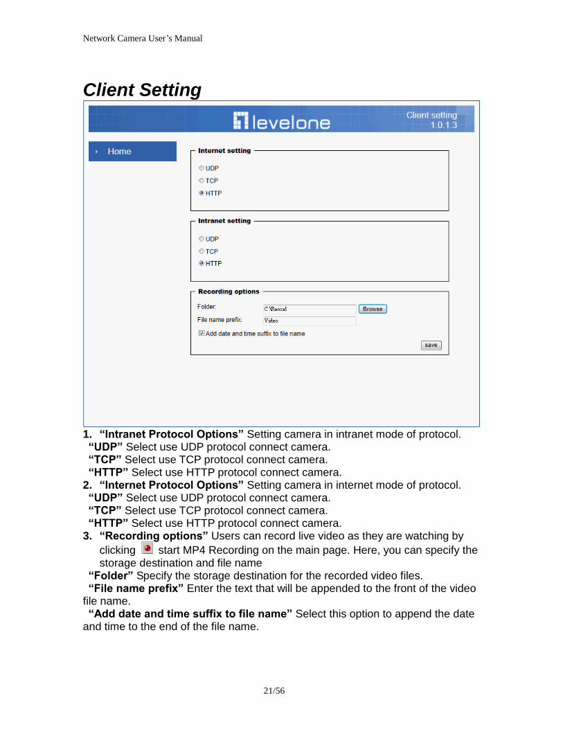
Network Camera Userrsquos Manual
2356
Definitions in Configuration
Please note that only the Administrator can access the system configuration Each category in the left column will be explained on the following pages
System parameters
1 ldquoGeneral Settingrdquo
(1) ldquoHost namerdquo The text displays the title on the top of the main page
Firmware version
Network Camera Userrsquos Manual
2456
2 ldquoTime Settingrdquo (1) ldquoTime zonerdquo Choose a time zone from the down arrow
(2) ldquoDaylight savingrdquo For summertime It will be one hour ahead
(3) ldquoCurrent Timerdquo Network camera set the current time
(A) ldquoKeep current date and timerdquo Click on this to keep the current date and time of the Network Camera An internal real-time clock maintains the date and time even when the power of the system is turned off
(B) ldquoSync with computer timerdquo Synchronize the date and time in the Network Camera according to the local computer
(C) ldquoManualrdquo Adjust the date and time by the Administrator
(D) ldquoAdjust by NTP serverrdquo Synchronize the time according NTP server over the Internet whenever the Network Camera is switched on It fails if the assigned time-server cannot be found
(a) ldquoNTP serverrdquo Assign the IP address or domain name of the time-server Leaving the text box blank connects the Network Camera to the default time-servers
(b) ldquoUpdate intervalrdquo Select 0 ~ 23 hours update with the time on the NTP server
3 ldquoDI statusrdquo Please go to Application page for setting the DI
Network Camera Userrsquos Manual
2556
Security
Security setting The administrator account name is ldquorootrdquo which is permanent and can not be deleted If you want to add more accounts in the Manage User column please set a password for the ldquorootrdquo account first 1 ldquoChange root passwordrdquo Change the Administratorrsquos password by typing in the new password identically in both text boxes The typed entries will be displayed as asterisks for security purposes After pressing ldquofinishrdquo the web browser will ask the Administrator for the new password to access
2 ldquoManage privilegerdquo You can modify the manage privilege of operators or viewers Check or uncheck the item then click finish to enable the settings
3 ldquoManage userrdquo (1) ldquoAdd a new userrdquo Administrators can add up to 20 user accounts
(A) Input the new userrsquos name and password (B) Select the privilege level for the new user account Click Finish to enable the
setting
(2) ldquoDelete a userrdquo Select an existing user name Click Finish to enable the setting
Network Camera Userrsquos Manual
2656
(3) ldquoUpdate a existing userrdquo Select an existing user name Administrators can modify userrsquos password and privilege Click Finish to enable the setting
Access rights are sorted by user privilege (Administrator Operator and Viewer) Only administrators can access the Configuration page Operators cannot access the Configuration page but can use the URL Commands to get and set the value of parameters Viewers access only the main page for live viewing
Network
Any changes made on this page will restart the system in order to validate the changes Make sure every field is entered correctly before clicking on ldquofinishrdquo
Network Camera Userrsquos Manual
2756
Network Setting ldquoLANrdquo amp ldquoPPPoErdquo The default type is LAN Select PPPoE if using ADSL
1 LAN
The default status is Get IP address automatically This could be tedious to perform software installation whenever the Network Camera starts Therefore once the network is set especially for the IP address should be entered correctly Select Use fixed IP address then the Network Camera will skip installation The Network Camera will automatically restart and operate normally after a power outage You can run IP installer to check the IP address assigned to the Network Camera if the IP address is forgotten or you can use the UPnP function provided by the Network Camera (MS Windows XP provides UPnP function at My Network Place)
(1) ldquoGet IP address automaticallyrdquo (2) ldquoUse fixed IP addressrdquo
- ldquoIP addressrdquo This is necessary for network identification - ldquoSubnet maskrdquo This is used to determine if the destination is in the same subnet The default value is ldquo2552552550rdquo - ldquoDefault routerrdquo This is a gateway used to forward frames to destinations in a different subnet Invalid router setting will fail the transmission to destinations in different subnet - ldquoPrimary DNSrdquo The primary domain name server that translates hostnames into IP addresses - ldquoSecondary DNSrdquo Secondary domain name server backups the Primary DNS - ldquoEnable UPnP presentation amp port forwardingrdquo Enable UPnP ability - ldquoHttp portrdquo This can be typed besides the default Port 80 Once the port is changed the users must make sure the change for the connection is successful For instance when the Administrator changes the HTTP port of the Network Camera which IP address is 192168020 from 80 or 1025 to 65535 the users must type in the web browser ldquohttp1921680208080rdquo instead of ldquohttp192168020rdquo
- ldquoRTSP Portrdquo RTSP port can be typed besides the default Port 554 - ldquoRTP Portrdquo The RTP port can be typed besides the default Port 54
Note Please set Video RTP port in even number after default value port 54 Then
Video RTCP potAudio RTP portAudio RTCP port will automatically set the
values in ascending
- ldquoRTSP Streaming access namesrdquo The RTSP streaming currently supports video only audio only and audiovideo To use the audiovideo stream type the URL asldquortsp613012543liveNsdprdquo
2 PPPoE If using the PPPoE interface you should fill the following settings from ISP
(1) ldquoUser namerdquo The login name of PPPoE account (2) ldquoPasswordrdquo The password of PPPoE account (3) ldquoConfirm passwordrdquo Input password again for confirmation
Network Camera Userrsquos Manual
2856
DDNS Setting 1 ldquoEnable DDNSrdquo This option turns on the DDNS function
2 ldquoip-discoveryrdquo In the Register column fill in the Host name (xxxx ip-discovery) Email Key and Confirm Key then click Register After a host name has been successfully created a success message will be displayed in the DDNS Registration Result column and messaging E-mail
3 ldquo3rd party DDNSrdquo This is enable or disable 3rd party DDNS 4 ldquoProviderrdquo The provider list contains hosts that provide DDNS services Please connect to the service providerrsquos website to make sure the service charges
5 ldquoHost Namerdquo If the User wants to use DDNS service this field must be filled Please input the hostname that is registered in the DDNS server
6 ldquoUser namerdquo The Username or E-mail field is necessary for logging in the DDNS server or notify the User of the new IP address Note when this field is input as ldquoUser namerdquo the following field must be input as ldquoPasswordrdquo
7 ldquoPasswordrdquo Please input the password or key to get the DDNS service
8 ldquofinishrdquo Click on this button to save modify settings for the DDNS service
Network Camera Userrsquos Manual
2956
Access list
Access list setting 1 How to control access permission by verifying the client PCrsquos IP
address General Settings General Settings
Add a rule to configure an AllowedDenied list Click Add to add a rule
Network Camera Userrsquos Manual
3056
to AllowedDenied list There are three types of rules for user to set up ldquoSinglerdquo This rule allows the user to add an IP address to the AllowedDenied list For example
ldquoNetworkrdquo This rule allows the user to assign a network address and corresponding subnet mask to the AllowDeny List The IP address is written in the CIDR format For example
Network Camera Userrsquos Manual
3156
ldquoRangerdquo This rule allows the user to assign a range of IP addresses to the AllowDeny List This rule is only applied to IPv4 For example
Network Camera Userrsquos Manual
3256
Audio and Video setting
Network Camera Userrsquos Manual
3356
General Setting 1 ldquoColor moderdquo Select use color or monochrome video display
2 ldquoVideo orientationrdquo The orientation of video
(1) ldquoFliprdquo Vertically rotate the video
(2) ldquoMirrorrdquo Horizontally rotates the video
3 ldquoEnvironmentrdquo The orientation of video
(1) ldquoindoorrdquo This option is usually selected when the Network Camera is placed in indoor environments
(2) ldquooutdoorrdquo This option is usually selected when the Network Camera is placed in outdoor environments
4 ldquoPower freqrdquo Select 50 Hz or 60Hz power line frequency
The fluorescent light will flash according to the power line frequency that
depends on local utility Change the frequency setting to eliminate uncomfortable flash image when the light source is only fluorescent light
Video Setting 1 ldquoContrastrdquo Adjust the image contrast level which ranges from -5 to +5 The default value is set to 0
2 ldquoBrightnessrdquo Adjust the image brightness level which ranges from -5 to +5 The default value is set to 0
3 ldquoSaturationrdquo Adjust the image saturation level which ranges from -5 to +5 The default value is set to 0
4 ldquoSharpnessrdquo Adjust the image sharpness level which ranges from -5 to +5 The default value is set to 0
5 ldquoEVrdquo Exposure value represent the expected target value of the luminance of
the weighting result of AE windows in the image and its tolerance as offset
6 ldquoGainrdquo In the slide bar of Gain there are also two sliders which represent the
limitations to control the maximum gain value and the minimum one respectively Normally the minimum value is to 1x for better quality
Network Camera Userrsquos Manual
3456
Exposure setting Here it provides 3 mode Auto Backlight and Customized Auto and
Backlight modes are 2 default settings for general purpose and backlight scene
respectively
Customized mode relates to the grid window above can be pointed on for
interesting areas Within the mode Customized 1615 grids windows can be chosen to match wherewhat you are interested in Push down left-button of mouse and drag to draw the grids for interesting areas or push down right-button of mouse and drag to clean the grids for insignificant areas
ldquoTarget Luminance and Offsetrdquo
These two slide bar Target Luminance and Offset represent the expected
target value of the luminance of the weighting result of AE windows in the image and its tolerance as offset For example target luminance is set to 100 and target offset is set to 20 that means the average luminance of the AE window should be in the range from 80 to 120 (100plusmn(10 When the actual luminance does not meet this range the AE function will adjust shutter and gain to meet it as possible In some extreme cases it cannot reach the target because the environment is too bright or dark When the environment is not consistent eg with big moving objects and the offset is too narrow the AE will act more frequently that will cause the background of view inconsistent The offset value is recommended to set 15~25 of target luminance
Network Camera Userrsquos Manual
3556
ldquoGainrdquo
In the slide bar of Gain there are also two sliders which represent the limitations
to control the maximum gain value and the minimum one respectively Normally the minimum value is to 1x for better quality It is not allowed if the maximum slider and the minimum one are set to the same value without adjustable interval Besides the noise will be increased if the actual gain is too large When the max slider is dragged over sensors max gain the slide bar will become deep blue to represent it will apply Mozart 3s digital gain which extend the max gain for very low light
ldquoShutter Speedrdquo
There are 2 fields minimal and maximal time for the range of Shutter Speed
The precision of the parameter is 11000000 sec but it is NOT actual precision of the shutter speed of the sensor The actual precision of the shutter speed depends on each sensorrsquos specification Here it will be rounded to approach sensorrsquos effective exposure time To avoid flickering or banding phenomenon under fluorescent light the actual shutter speed will be locked at 1120 160
130 if Power Line Frequency is 60Hz or 1100 150 125 if Power Line
Frequency is 50Hz The setting of Power Line Frequency is on the sub-tab Video
and Audio The exposure may not be stable if the maximum value and the minimum one are set to the same value without adjustable interval Besides the frame rate will drop down if the actual shutter speed is too slow to meet expected frame rate
Noise reduction
Provides 2D and 3D features
Wide Dynamic Range Enable Wide Dynamic Range auto in different level to improve the exposure when both bright and dark areas simultaneously in the field of view of the camera The default is off
Infrared Led Setting 1 ldquoInfrared LED Controlrdquo IR led for Day and Night (Option) User can turn onoff the built-in IR led This function is very useful under low illumination environment
(1) ldquoAutordquo Select IR sensitivity from 0 to 4
(2) ldquoManualrdquo Turn onoff the IR led manually
- ldquoTurn onrdquo Turn on led - ldquoTurn offrdquo Turn off led
2 ldquoLow lux moderdquo The video quality will be improved when the camera is in low lux environment (1) ldquoDisable dark moderdquo Disable low lux mode
(2) ldquoEnable dark moderdquo Enable low lux mode
Network Camera Userrsquos Manual
3656
Video output Setting 1 ldquovideo outputrdquo Can switch between NTSC and PAL
Audio Setting 1 ldquoMuterdquo Audio mute
2 ldquoMicrophone rdquo External microphone
3 ldquoMic Volumerdquo Adjust microphone volume which ranges from 1 to 46
Video record
Schedule mode
(1) ldquoEvery dayrdquo EnableDisable every day application
(2) ldquoWeek dayrdquo EnableDisable week day application
(3)ldquoSelected dayrdquo EnableDisable selected day application
Schedule information
(1) Enter the ldquoStart timerdquo and ldquoStop timerdquo for day mode Note that the time format is [hhmm] and is expressed in 24-hour clock time By default the start and end time of day mode are set to 010000 and 235959
Network Camera Userrsquos Manual
3756
(2)ldquoSunrdquoldquoMonrdquoldquoTuerdquoldquoWedrdquoldquoThurdquoldquoFrirdquoldquoSatrdquo Select the days of the week to perform the application
(3) ldquoStart dayrdquo and ldquoStart timerdquo as the start timing the time ldquoEnd dayrdquo and ldquoEnd timerdquo as the end timing the time
(4) ldquoEnable cyclic recordingrdquo The cyclic recording function is enabled during the transaction stage when a storage space is full and the incoming streaming data is about to overwrite the previously saved videos
Record parameters (1)Source Select a stream for the recording source
(2)Recording interval Select the recording time interval
(3)Prefix file name You can setting the file name and enable or disable to add the date and time on file name
Response mode There are two choices of server types available NAS SD Card Select the item to display the detailed configuration options
(1)rdquoNASrdquo
--ldquoNAS server addressrdquo Enter IP address of the NAS server
--ldquoNAS shared directoryrdquo Enter the NAS shared directory path --ldquoWorkgrouprdquo Enter the NAS workgroup parameter --ldquoUser accountrdquo Enter the login name of the NAS account --ldquoUser passwordrdquo Enter the password of the NAS account Note Video record with the Application must be set to the same shared directory
path If you would like do detail recording settings or multi-channel recording please install bundled 64CH recording software in CD
Network Camera Userrsquos Manual
3856
Stream
Audio codec setting
(1)ldquoAudio codec typerdquo There are two choices of audio codec types
available rdquoAMRrdquo ldquoAACrdquo and rdquoG711rdquo
(2) ldquoBit raterdquo -- ldquoAMRrdquo The bit rates are selectable at the following rates
47505150590067007400795010200 and 12200
-- ldquoAACrdquo The bit rates are selectable at the following rates 8Kbps16Kbps 24Kbps and 32Kbps
-- ldquoG711rdquo pcmu and pcma
Video codec setting (1) ldquoSelect Streamrdquo The Network Camera supports ldquoStream 1rdquoand ldquoStream 2rdquo
(2) ldquoVideo codecrdquo The Network Camera supports three kind of video compression mode ldquoH264rdquo or ldquoMPEG4rdquo or ldquoMJPEGrdquo User can choose one of
Network Camera Userrsquos Manual
3956
these compression modes based on requirement or application
(3) ldquoVideo sizerdquo Click the down arrow to choose the quality of image (1920x1080 1280x1024 1280x800 640x480 320x240 176x144)
(4) ldquoConnection typerdquo User can select this button to choose the better video amp links quality (Internet mode or Intranet mode)
(5) ldquoFrame raterdquo This limits the maximal refresh frame rate per second Set the frame rate higher for a smoother video quality
(6) ldquoIntra frame periodrdquo Determine how often to plant an ldquoI framerdquo The shorter the duration the more likely you will get a better video quality but at the cost of higher network bandwidth consumption
(7) ldquoVideo Quality typerdquo Setting optimizes bandwidth utilization and video quality
-- ldquoConstant bit raterdquo User can adjust the video quality from 20 Kbps to 12 Mbps
-- ldquoFixed qualityrdquo user can select from lowest quality to get best quality according The ldquoQualityrdquo are selectable at the following rates From 1 to 20
Snapshot and time display setting Adjust the photo size specifications and choose whether to mark time on the video and photo
Network Camera Userrsquos Manual
4056
Application
Schedule mode
(1) ldquoEvery dayrdquo EnableDisable every day application
(2) ldquoWeek dayrdquo EnableDisable week day application
(3) ldquoSelected dayrdquo EnableDisable selected day application
Schedule information (1) Enter the ldquoStart timerdquo and ldquoStop timerdquo for day mode
Note that the time format is [hhmmss] and is expressed in 24-hour clock time By default the start and end time of day mode are set to 010000 and 235959
(2) ldquoSunrdquoldquoMonrdquoldquoTuerdquoldquoWedrdquoldquoThurdquoldquoFrirdquoldquoSatrdquo Select the days of the week to perform the application
(3) ldquoStart dayrdquo and ldquoStart timerdquo as the start timing the time ldquoEnd dayrdquo and ldquoEnd timerdquo as the end timing the time
Trigger mode
(1) ldquoVideo motion detectionrdquo EnableDisable video motion application (2) ldquoPeriodicallyrdquo This option allows the Network Camera to trigger
periodically for every other defined minute
Network Camera Userrsquos Manual
4156
(3) ldquoDigital inputrdquo This option allows the Network Camera to use an external digital input device or sensor as a trigger source Depending on your application there are many choices of digital input devices on the market which helps to detect changes in temperature vibration sound and light etc
parameters
(1) ldquoMotion parametersrdquo Higher sensitivity and small threshold will allow easier motion detection
(2) ldquoPeriod parametersrdquo This option allows the Network Camera to trigger periodically for every other defined seconds Up to 999 seconds are allowed
(3) ldquoDigital input parametersrdquo Select the digital input type and set trigger time
Media mode There are four choices of media types available ldquoSnapshotrdquo ldquoMessagerdquo ldquoRecord(Motion Detection only)rdquo and ldquoSystem logrdquo
Snapshot amp Record file setting You can setting the file name and enable or disable to add the date and time on file name Can setting the digital output duration seconds Response mode There are four choices of server types available Email FTP NAS and SD Card storage Select the item to display the detailed configuration options
(1)ldquoEmailrdquo -- ldquoEmail security moderdquo If your SMTP server requires a secure connection (SSL or TLS) check This server requires a secure connection (SSL or TLS) -- ldquoSender emailrdquo address Enter the email address of the sender -- ldquoRecipient emailrdquo address Enter the email address of the recipient
-- ldquoServer addressrdquo Enter the domain name or IP address of the email server
--ldquoUser namerdquo Enter the user name of the email account if necessary
--ldquoPasswordrdquo Enter the password of the email account if necessary
--ldquoServer portrdquo The default mail server port is set to 25 You can also manually set another port
(2)rdquoFTPrdquo -- ldquoServer addressrdquo Enter the domain name or IP address of the FTP server
-- ldquoServer portrdquo By default the FTP server port is set to 21
-- ldquoUser namerdquo Enter the login name of the FTP account
-- ldquoPasswordrdquo Enter the password of the FTP account
-- ldquoFTP folder namerdquo Enter the folder where the media file will be placed If the folder name does not exist the Network Camera will create one on the FTP server
(3)rdquoHTTP rdquo
-- ldquoURLrdquo Enter the URL of the HTTP server
-- ldquoUser accountrdquo Enter the user name if necessary -- ldquoUser passwordrdquo Enter the password if necessary
(4)rdquoNASrdquo --ldquoNAS server addressrdquo Enter IP address of the NAS server
--ldquoNAS shared directoryrdquo Enter the NAS shared directory path
Network Camera Userrsquos Manual
4256
--ldquoWorkgrouprdquo Enter the NAS workgroup parameter --ldquoUser accountrdquo Enter the login name of the NAS account --ldquoUser passwordrdquo Enter the password of the NAS account Note Video record with the Application must be set to the same shared directory
path If you would like do detail recording settings or multi-channel recording please install bundled 64CH recording software in CD
Network Camera Userrsquos Manual
4356
Storage
Manage the storage device
S torage Status Here show the storage device information
NAS server setting
1
2
3
Network Camera Userrsquos Manual
4456
(1) ldquoNAS Host namerdquo Choose and input the NAS Host name of this camera
(2) ldquoWorkgrouprdquo Input the name of Workgroup You can see the NAS Host name you input in the same workgroup with your PC Then you can connect to this device and download the files easily from SD card which is inserted to this camera
File operation Move the mouse over the file Press the mouse right button that Right-click menu is displayed You can delete files Move the mouse over the directory Press the mouse left button that the file structure expand Press the mouse right button that Right-click menu is displayed You can choose upload or delete files NOTEAllow the user to upload or delete files when the storage device is not write-
protected If the SD card canrsquot be detected please link to the following URL httpwwwsdcardorgconsumersformatter to download the ldquoSD Formatter Kitrdquo formatting your SD card
Network Camera Userrsquos Manual
4556
Syslog
The Network camera supports log the system messages on remote server The protocol is compliant to RFC 3164 If you have external Linux server with sys log service use ldquo-rrdquo option to turn on the facility for receiving log from remote machine Or you can use some software on Windows that is compliant to RFC 3164 An example is Kiwi Syslog Daemon Visit httpwwwkiwisyslogcomkiwi-syslog-daemon-overview Check ldquoSetuprdquo and ldquoEnablerdquo then input the ldquoIP addressrdquo and ldquoportrdquo number of the log server to enable the remote log facility In the ldquoCurrent logrdquo it displays the current system log file The content of the log provides useful information about configuration and connection after system boot- up
ldquofinishrdquo Click on this button to save modify settings
Network Camera Userrsquos Manual
4656
Status and Parameters
User can find a lot of information about the system such as ldquoUpnp port forwardingrdquo
ldquoTraversing NATrdquo ldquoPublic IPrdquo and so on User also can get the number of current viewer of the Network Camera here
Network Camera Userrsquos Manual
4756
Maintenance
1 ldquoReboot systemrdquo The ldquoRebootrdquo button will reboot the Network Camera Itrsquos useful while the Network Camera got problem 2 ldquoRestore systemrdquo Click on ldquoRestorerdquo button on the configuration page to restore the factory default settings Restore all settings to factory default except settings in ldquoNetwork type rdquo and ldquoRoot Passwordrdquo The system will restart and require the installer program to set up the network again
3 ldquoCalibraterdquo Recalibrate the auto focus position to the default range to recover the tolerance caused by some external forces 4 ldquoExportImport filerdquo -- Export setting backup file Click to export all parameters for the device and user-defined scripts
-- Upload setting backup file Click Browsehellip to upload a setting backup file Please note that the model and firmware version of the device should be the same as the setting backup file If you have set up a fixed IP or other special settings for your device it is not suggested to upload a settings backup file
4 ldquoUpgrade firmwarerdquo Select the firmware file and click upgrade button Please be aware that you should not turn off the power during updating the firmware and wait for finish message
Network Camera Userrsquos Manual
4856
Warning The upgrade firmware procedure cannot be interrupted If the power
andor network connection are broken during the procedure it might possibly cause serious damage to the Network Camera
Note When upgrade firmware please wait for 120~210 seconds and then you can connect to Network Camera again The system will restart and require the installer program to set up the network again
Network Camera Userrsquos Manual
4956
Appendix
A Troubleshooting amp Frequently Asked Questions Q1 Status led does not light up
A1 First make sure that「ConfigurationgtSystemgtTurn off the LED indicator」is disabled
If it is check the item and the led should light up Second if red led does not light up please check that the power adapter in the package is plugged correctly And last if green led does not light up please check that category 5 UTP cable is plugged correctly If the problem is still not solved please contact your dealer for further help
Q2 What kind of Ethernet cable is used by network camera
A2 The network Camera uses Category 5 UTP cable allowing 10 andor 100 Base-T networking
Q3 The Network Camera will be installed and work if a firewall exists on
the network
A3 There are two way to set up the IP camera at Internet (1) By UPnP Port Forwarding 1 Select an IP router It must support UPnP port forwarding and enable this function
first
2 Connect camera RJ45 cable to IP router and the router is also connected to Internet
3 Plug power cord to camera
4 Go to camera Network page Enable UPnP port forwarding
5 Check camera status we can see the ports had been successfully opened
Network Camera Userrsquos Manual
5056
6Type IP address8080 at browser Then you can see camera through Internet
7You can also type the ddns name at below label of camera on browser URL field For example you may type ah00001ip-discoverycom8080 (2) By Setting Port Forwarding Manually 1 Select a router Set the port forwarding as following
Network Camera Userrsquos Manual
5156
PS Port 80 is HTTP Port port 53 is stream port port 554 is RTSP port and port 443 is HTTPS port 2Go to camera Network page Disable UPnP port forwarding function
Network Camera Userrsquos Manual
5256
3 Type IP address at browser Then you can see camera through Internet
4 You can also type the ddns name at below label of camera on browser URL field For example you may type ah00001ip-discoverycom
Note The firewall software at PC may block the transfer of network camera Please remove or stop the kind software
Q4 How can I find the network camera in the local area network
A4 By using the IP Finder2 program or using UPnP to find it
Q5 IP Finder2 program cannot find Network Camera in the local area
network at first time
A5 Make sure the subnet of network camera is same as your PC If the local area network supports DHCP the camera is ldquoGet IP address automaticallyrdquo in the ldquoNetworkrdquo page default If the local area network does not support DHCP change your PC IP address to ldquo1921680xxxrdquo
Network Camera Userrsquos Manual
5356
Q6 How can I restore the network camera to default value
A6 Use a gem clip to press on the inside button Network camera begins to restore default value You can also press the button ldquoFactoryrdquo in ldquoMaintenancerdquo page to restore the default value
Q7 I cannot play the recorded video file
A7 Install the audio codec in the CD and use the Windows Media Player 10 or later to play the ASF or AVI file recorded by the network camera
Q8 Infrared led does not light up
A8 Check「ConfigurationgtAudio and VideogtInfrared LED Control」 is ldquoAutordquo or
ldquoManual》Turn onrdquo
Q9 The network camera cannot focus accurately
A9 (1) The lens is dirty or dust is attached Clean the lens with lens cleaner And then adjust the camera focus manually (2) The image may be out of focus If the object is too near move the object away from Network Camera
Q10 The cover of network camera is warm Is it normal
A10 Network camera is a precision device The internal material has the operational temperature and it is normal when user touch the cover feels warm It is recommended to put the network camera at aired place and not put at any other device
Q11 The process of upgrade firmware abort
A11 Contact your dealer for further help
Q12 Cannot access the login page and other web pages of Network
Network Camera Userrsquos Manual
5456
Camera from Internet Explorer
A12 bull May be due to the network cable Try correcting your network cable and configuration Test the network interface by connecting a local computer to the Network Camera via a crossover cable bull Make sure the Internet connection and setting is ok bull Make sure enter the IP address of Internet Explorer is correct If Network Camera has a dynamic address it may have changed since you last checked it bull Network congestion may prevent the web page appearing quickly Wait for a while The IP address and Subnet Mask of the PC and Network Camera must be in the same class of the private IP address on the LAN bull Make sure the http port used by the Network Camera default=80 is forward to the Network Camerarsquos private IP address bull The port number assigned in your Network Camera might not be available via Internet Check your ISP for available port bull The proxy server may prevent you from connecting directly to Network Camera set up not to use the proxy server bull Confirm that Default Gateway address is correct bull The router needs Port Forwarding feature Refer to your routers manual for details bull Packet Filtering of the router may prohibit access from an external network Refer to your routers manual for details bull Access Network Camera from the Internet with the global IP address of the router and port number of Network Camera bull Some routers reject the global IP address to access Network Camera on the same LAN Access with the private IP address and correct port number of Network Camera bull When you use DDNS you need to set Default Gateway and DNS server address bull If itrsquos not working after above procedure reset Network Camera to default setting and installed it again bull Maybe the IP Address of the Network Camera is already being used by another device or computer bull If the problem is not solved the Network Camera might be faulty Contact your dealer for further help
Network Camera Userrsquos Manual
5556
B Technical specifications
- System RAM 4G bit DDRⅢ
ROM 16MB Flash ROM
- Camera specification 127 inch color CMOS sensor Resolution 1920x1080 10LuxF20 AGC AWB AEC
- Infrared Led High power IR Leds 25~30 M visible AutoManual mode
- Lens 3X optical zoom lens auto iris auto focus f = 28~ 12mm F18 Fov(D) 136deg ~ 39deg
- Protocol TCPIP HTTPUDP SMTP FTP DDNS UPnP Telnet NTP PPPoE RTSP RTPRTCPDHCP and DNS
- Video Resolution Up to 30 frames at 176x144 Up to 30 frames at 320x240 Up to 30 frames at 640x480 Up to 30 frames at 1280x800 Up to 30 frames at 1280x1024 Up to 30 frames at 1920x1080
- Algorithm supported H264MPEG4MJPEG dual codec for streaming video JPEG for still image
- Audio AMRAACG711 External MIC input 2-way audio
- Physical 10 baseT100 baseT and 1000 baseT Fast
Ethernet auto negotiation
- Power Input 100-240VAC 5060Hz 07A Output 12VDC 15A Consumption Max 12 W Support 8023af compliant Power over Ethernet
- EMI amp Safety CE FCC
- Dimension Length 165mm Diameter 75mm
- Operating Environment Temperature -20 ~ 50
Humidity 85 RH
- Weight NET 600g With bracket 800g
Network Camera Userrsquos Manual
5656
Notification of Compliance Appendix C
Europe - EU Declaration of Conformity
For complete DoC please visit httpgloballevel1comdownloadsphpaction=init
GPL License Agreement GPL may be included in this product to view the GPL license agreement goes to httpdownloadlevel1comlevel1gplGPLpdf For GNU General Public License (GPL) related information please visit httpgloballevel1comdownloadsphpaction=init
Network Camera Userrsquos Manual
2456
2 ldquoTime Settingrdquo (1) ldquoTime zonerdquo Choose a time zone from the down arrow
(2) ldquoDaylight savingrdquo For summertime It will be one hour ahead
(3) ldquoCurrent Timerdquo Network camera set the current time
(A) ldquoKeep current date and timerdquo Click on this to keep the current date and time of the Network Camera An internal real-time clock maintains the date and time even when the power of the system is turned off
(B) ldquoSync with computer timerdquo Synchronize the date and time in the Network Camera according to the local computer
(C) ldquoManualrdquo Adjust the date and time by the Administrator
(D) ldquoAdjust by NTP serverrdquo Synchronize the time according NTP server over the Internet whenever the Network Camera is switched on It fails if the assigned time-server cannot be found
(a) ldquoNTP serverrdquo Assign the IP address or domain name of the time-server Leaving the text box blank connects the Network Camera to the default time-servers
(b) ldquoUpdate intervalrdquo Select 0 ~ 23 hours update with the time on the NTP server
3 ldquoDI statusrdquo Please go to Application page for setting the DI
Network Camera Userrsquos Manual
2556
Security
Security setting The administrator account name is ldquorootrdquo which is permanent and can not be deleted If you want to add more accounts in the Manage User column please set a password for the ldquorootrdquo account first 1 ldquoChange root passwordrdquo Change the Administratorrsquos password by typing in the new password identically in both text boxes The typed entries will be displayed as asterisks for security purposes After pressing ldquofinishrdquo the web browser will ask the Administrator for the new password to access
2 ldquoManage privilegerdquo You can modify the manage privilege of operators or viewers Check or uncheck the item then click finish to enable the settings
3 ldquoManage userrdquo (1) ldquoAdd a new userrdquo Administrators can add up to 20 user accounts
(A) Input the new userrsquos name and password (B) Select the privilege level for the new user account Click Finish to enable the
setting
(2) ldquoDelete a userrdquo Select an existing user name Click Finish to enable the setting
Network Camera Userrsquos Manual
2656
(3) ldquoUpdate a existing userrdquo Select an existing user name Administrators can modify userrsquos password and privilege Click Finish to enable the setting
Access rights are sorted by user privilege (Administrator Operator and Viewer) Only administrators can access the Configuration page Operators cannot access the Configuration page but can use the URL Commands to get and set the value of parameters Viewers access only the main page for live viewing
Network
Any changes made on this page will restart the system in order to validate the changes Make sure every field is entered correctly before clicking on ldquofinishrdquo
Network Camera Userrsquos Manual
2756
Network Setting ldquoLANrdquo amp ldquoPPPoErdquo The default type is LAN Select PPPoE if using ADSL
1 LAN
The default status is Get IP address automatically This could be tedious to perform software installation whenever the Network Camera starts Therefore once the network is set especially for the IP address should be entered correctly Select Use fixed IP address then the Network Camera will skip installation The Network Camera will automatically restart and operate normally after a power outage You can run IP installer to check the IP address assigned to the Network Camera if the IP address is forgotten or you can use the UPnP function provided by the Network Camera (MS Windows XP provides UPnP function at My Network Place)
(1) ldquoGet IP address automaticallyrdquo (2) ldquoUse fixed IP addressrdquo
- ldquoIP addressrdquo This is necessary for network identification - ldquoSubnet maskrdquo This is used to determine if the destination is in the same subnet The default value is ldquo2552552550rdquo - ldquoDefault routerrdquo This is a gateway used to forward frames to destinations in a different subnet Invalid router setting will fail the transmission to destinations in different subnet - ldquoPrimary DNSrdquo The primary domain name server that translates hostnames into IP addresses - ldquoSecondary DNSrdquo Secondary domain name server backups the Primary DNS - ldquoEnable UPnP presentation amp port forwardingrdquo Enable UPnP ability - ldquoHttp portrdquo This can be typed besides the default Port 80 Once the port is changed the users must make sure the change for the connection is successful For instance when the Administrator changes the HTTP port of the Network Camera which IP address is 192168020 from 80 or 1025 to 65535 the users must type in the web browser ldquohttp1921680208080rdquo instead of ldquohttp192168020rdquo
- ldquoRTSP Portrdquo RTSP port can be typed besides the default Port 554 - ldquoRTP Portrdquo The RTP port can be typed besides the default Port 54
Note Please set Video RTP port in even number after default value port 54 Then
Video RTCP potAudio RTP portAudio RTCP port will automatically set the
values in ascending
- ldquoRTSP Streaming access namesrdquo The RTSP streaming currently supports video only audio only and audiovideo To use the audiovideo stream type the URL asldquortsp613012543liveNsdprdquo
2 PPPoE If using the PPPoE interface you should fill the following settings from ISP
(1) ldquoUser namerdquo The login name of PPPoE account (2) ldquoPasswordrdquo The password of PPPoE account (3) ldquoConfirm passwordrdquo Input password again for confirmation
Network Camera Userrsquos Manual
2856
DDNS Setting 1 ldquoEnable DDNSrdquo This option turns on the DDNS function
2 ldquoip-discoveryrdquo In the Register column fill in the Host name (xxxx ip-discovery) Email Key and Confirm Key then click Register After a host name has been successfully created a success message will be displayed in the DDNS Registration Result column and messaging E-mail
3 ldquo3rd party DDNSrdquo This is enable or disable 3rd party DDNS 4 ldquoProviderrdquo The provider list contains hosts that provide DDNS services Please connect to the service providerrsquos website to make sure the service charges
5 ldquoHost Namerdquo If the User wants to use DDNS service this field must be filled Please input the hostname that is registered in the DDNS server
6 ldquoUser namerdquo The Username or E-mail field is necessary for logging in the DDNS server or notify the User of the new IP address Note when this field is input as ldquoUser namerdquo the following field must be input as ldquoPasswordrdquo
7 ldquoPasswordrdquo Please input the password or key to get the DDNS service
8 ldquofinishrdquo Click on this button to save modify settings for the DDNS service
Network Camera Userrsquos Manual
2956
Access list
Access list setting 1 How to control access permission by verifying the client PCrsquos IP
address General Settings General Settings
Add a rule to configure an AllowedDenied list Click Add to add a rule
Network Camera Userrsquos Manual
3056
to AllowedDenied list There are three types of rules for user to set up ldquoSinglerdquo This rule allows the user to add an IP address to the AllowedDenied list For example
ldquoNetworkrdquo This rule allows the user to assign a network address and corresponding subnet mask to the AllowDeny List The IP address is written in the CIDR format For example
Network Camera Userrsquos Manual
3156
ldquoRangerdquo This rule allows the user to assign a range of IP addresses to the AllowDeny List This rule is only applied to IPv4 For example
Network Camera Userrsquos Manual
3256
Audio and Video setting
Network Camera Userrsquos Manual
3356
General Setting 1 ldquoColor moderdquo Select use color or monochrome video display
2 ldquoVideo orientationrdquo The orientation of video
(1) ldquoFliprdquo Vertically rotate the video
(2) ldquoMirrorrdquo Horizontally rotates the video
3 ldquoEnvironmentrdquo The orientation of video
(1) ldquoindoorrdquo This option is usually selected when the Network Camera is placed in indoor environments
(2) ldquooutdoorrdquo This option is usually selected when the Network Camera is placed in outdoor environments
4 ldquoPower freqrdquo Select 50 Hz or 60Hz power line frequency
The fluorescent light will flash according to the power line frequency that
depends on local utility Change the frequency setting to eliminate uncomfortable flash image when the light source is only fluorescent light
Video Setting 1 ldquoContrastrdquo Adjust the image contrast level which ranges from -5 to +5 The default value is set to 0
2 ldquoBrightnessrdquo Adjust the image brightness level which ranges from -5 to +5 The default value is set to 0
3 ldquoSaturationrdquo Adjust the image saturation level which ranges from -5 to +5 The default value is set to 0
4 ldquoSharpnessrdquo Adjust the image sharpness level which ranges from -5 to +5 The default value is set to 0
5 ldquoEVrdquo Exposure value represent the expected target value of the luminance of
the weighting result of AE windows in the image and its tolerance as offset
6 ldquoGainrdquo In the slide bar of Gain there are also two sliders which represent the
limitations to control the maximum gain value and the minimum one respectively Normally the minimum value is to 1x for better quality
Network Camera Userrsquos Manual
3456
Exposure setting Here it provides 3 mode Auto Backlight and Customized Auto and
Backlight modes are 2 default settings for general purpose and backlight scene
respectively
Customized mode relates to the grid window above can be pointed on for
interesting areas Within the mode Customized 1615 grids windows can be chosen to match wherewhat you are interested in Push down left-button of mouse and drag to draw the grids for interesting areas or push down right-button of mouse and drag to clean the grids for insignificant areas
ldquoTarget Luminance and Offsetrdquo
These two slide bar Target Luminance and Offset represent the expected
target value of the luminance of the weighting result of AE windows in the image and its tolerance as offset For example target luminance is set to 100 and target offset is set to 20 that means the average luminance of the AE window should be in the range from 80 to 120 (100plusmn(10 When the actual luminance does not meet this range the AE function will adjust shutter and gain to meet it as possible In some extreme cases it cannot reach the target because the environment is too bright or dark When the environment is not consistent eg with big moving objects and the offset is too narrow the AE will act more frequently that will cause the background of view inconsistent The offset value is recommended to set 15~25 of target luminance
Network Camera Userrsquos Manual
3556
ldquoGainrdquo
In the slide bar of Gain there are also two sliders which represent the limitations
to control the maximum gain value and the minimum one respectively Normally the minimum value is to 1x for better quality It is not allowed if the maximum slider and the minimum one are set to the same value without adjustable interval Besides the noise will be increased if the actual gain is too large When the max slider is dragged over sensors max gain the slide bar will become deep blue to represent it will apply Mozart 3s digital gain which extend the max gain for very low light
ldquoShutter Speedrdquo
There are 2 fields minimal and maximal time for the range of Shutter Speed
The precision of the parameter is 11000000 sec but it is NOT actual precision of the shutter speed of the sensor The actual precision of the shutter speed depends on each sensorrsquos specification Here it will be rounded to approach sensorrsquos effective exposure time To avoid flickering or banding phenomenon under fluorescent light the actual shutter speed will be locked at 1120 160
130 if Power Line Frequency is 60Hz or 1100 150 125 if Power Line
Frequency is 50Hz The setting of Power Line Frequency is on the sub-tab Video
and Audio The exposure may not be stable if the maximum value and the minimum one are set to the same value without adjustable interval Besides the frame rate will drop down if the actual shutter speed is too slow to meet expected frame rate
Noise reduction
Provides 2D and 3D features
Wide Dynamic Range Enable Wide Dynamic Range auto in different level to improve the exposure when both bright and dark areas simultaneously in the field of view of the camera The default is off
Infrared Led Setting 1 ldquoInfrared LED Controlrdquo IR led for Day and Night (Option) User can turn onoff the built-in IR led This function is very useful under low illumination environment
(1) ldquoAutordquo Select IR sensitivity from 0 to 4
(2) ldquoManualrdquo Turn onoff the IR led manually
- ldquoTurn onrdquo Turn on led - ldquoTurn offrdquo Turn off led
2 ldquoLow lux moderdquo The video quality will be improved when the camera is in low lux environment (1) ldquoDisable dark moderdquo Disable low lux mode
(2) ldquoEnable dark moderdquo Enable low lux mode
Network Camera Userrsquos Manual
3656
Video output Setting 1 ldquovideo outputrdquo Can switch between NTSC and PAL
Audio Setting 1 ldquoMuterdquo Audio mute
2 ldquoMicrophone rdquo External microphone
3 ldquoMic Volumerdquo Adjust microphone volume which ranges from 1 to 46
Video record
Schedule mode
(1) ldquoEvery dayrdquo EnableDisable every day application
(2) ldquoWeek dayrdquo EnableDisable week day application
(3)ldquoSelected dayrdquo EnableDisable selected day application
Schedule information
(1) Enter the ldquoStart timerdquo and ldquoStop timerdquo for day mode Note that the time format is [hhmm] and is expressed in 24-hour clock time By default the start and end time of day mode are set to 010000 and 235959
Network Camera Userrsquos Manual
3756
(2)ldquoSunrdquoldquoMonrdquoldquoTuerdquoldquoWedrdquoldquoThurdquoldquoFrirdquoldquoSatrdquo Select the days of the week to perform the application
(3) ldquoStart dayrdquo and ldquoStart timerdquo as the start timing the time ldquoEnd dayrdquo and ldquoEnd timerdquo as the end timing the time
(4) ldquoEnable cyclic recordingrdquo The cyclic recording function is enabled during the transaction stage when a storage space is full and the incoming streaming data is about to overwrite the previously saved videos
Record parameters (1)Source Select a stream for the recording source
(2)Recording interval Select the recording time interval
(3)Prefix file name You can setting the file name and enable or disable to add the date and time on file name
Response mode There are two choices of server types available NAS SD Card Select the item to display the detailed configuration options
(1)rdquoNASrdquo
--ldquoNAS server addressrdquo Enter IP address of the NAS server
--ldquoNAS shared directoryrdquo Enter the NAS shared directory path --ldquoWorkgrouprdquo Enter the NAS workgroup parameter --ldquoUser accountrdquo Enter the login name of the NAS account --ldquoUser passwordrdquo Enter the password of the NAS account Note Video record with the Application must be set to the same shared directory
path If you would like do detail recording settings or multi-channel recording please install bundled 64CH recording software in CD
Network Camera Userrsquos Manual
3856
Stream
Audio codec setting
(1)ldquoAudio codec typerdquo There are two choices of audio codec types
available rdquoAMRrdquo ldquoAACrdquo and rdquoG711rdquo
(2) ldquoBit raterdquo -- ldquoAMRrdquo The bit rates are selectable at the following rates
47505150590067007400795010200 and 12200
-- ldquoAACrdquo The bit rates are selectable at the following rates 8Kbps16Kbps 24Kbps and 32Kbps
-- ldquoG711rdquo pcmu and pcma
Video codec setting (1) ldquoSelect Streamrdquo The Network Camera supports ldquoStream 1rdquoand ldquoStream 2rdquo
(2) ldquoVideo codecrdquo The Network Camera supports three kind of video compression mode ldquoH264rdquo or ldquoMPEG4rdquo or ldquoMJPEGrdquo User can choose one of
Network Camera Userrsquos Manual
3956
these compression modes based on requirement or application
(3) ldquoVideo sizerdquo Click the down arrow to choose the quality of image (1920x1080 1280x1024 1280x800 640x480 320x240 176x144)
(4) ldquoConnection typerdquo User can select this button to choose the better video amp links quality (Internet mode or Intranet mode)
(5) ldquoFrame raterdquo This limits the maximal refresh frame rate per second Set the frame rate higher for a smoother video quality
(6) ldquoIntra frame periodrdquo Determine how often to plant an ldquoI framerdquo The shorter the duration the more likely you will get a better video quality but at the cost of higher network bandwidth consumption
(7) ldquoVideo Quality typerdquo Setting optimizes bandwidth utilization and video quality
-- ldquoConstant bit raterdquo User can adjust the video quality from 20 Kbps to 12 Mbps
-- ldquoFixed qualityrdquo user can select from lowest quality to get best quality according The ldquoQualityrdquo are selectable at the following rates From 1 to 20
Snapshot and time display setting Adjust the photo size specifications and choose whether to mark time on the video and photo
Network Camera Userrsquos Manual
4056
Application
Schedule mode
(1) ldquoEvery dayrdquo EnableDisable every day application
(2) ldquoWeek dayrdquo EnableDisable week day application
(3) ldquoSelected dayrdquo EnableDisable selected day application
Schedule information (1) Enter the ldquoStart timerdquo and ldquoStop timerdquo for day mode
Note that the time format is [hhmmss] and is expressed in 24-hour clock time By default the start and end time of day mode are set to 010000 and 235959
(2) ldquoSunrdquoldquoMonrdquoldquoTuerdquoldquoWedrdquoldquoThurdquoldquoFrirdquoldquoSatrdquo Select the days of the week to perform the application
(3) ldquoStart dayrdquo and ldquoStart timerdquo as the start timing the time ldquoEnd dayrdquo and ldquoEnd timerdquo as the end timing the time
Trigger mode
(1) ldquoVideo motion detectionrdquo EnableDisable video motion application (2) ldquoPeriodicallyrdquo This option allows the Network Camera to trigger
periodically for every other defined minute
Network Camera Userrsquos Manual
4156
(3) ldquoDigital inputrdquo This option allows the Network Camera to use an external digital input device or sensor as a trigger source Depending on your application there are many choices of digital input devices on the market which helps to detect changes in temperature vibration sound and light etc
parameters
(1) ldquoMotion parametersrdquo Higher sensitivity and small threshold will allow easier motion detection
(2) ldquoPeriod parametersrdquo This option allows the Network Camera to trigger periodically for every other defined seconds Up to 999 seconds are allowed
(3) ldquoDigital input parametersrdquo Select the digital input type and set trigger time
Media mode There are four choices of media types available ldquoSnapshotrdquo ldquoMessagerdquo ldquoRecord(Motion Detection only)rdquo and ldquoSystem logrdquo
Snapshot amp Record file setting You can setting the file name and enable or disable to add the date and time on file name Can setting the digital output duration seconds Response mode There are four choices of server types available Email FTP NAS and SD Card storage Select the item to display the detailed configuration options
(1)ldquoEmailrdquo -- ldquoEmail security moderdquo If your SMTP server requires a secure connection (SSL or TLS) check This server requires a secure connection (SSL or TLS) -- ldquoSender emailrdquo address Enter the email address of the sender -- ldquoRecipient emailrdquo address Enter the email address of the recipient
-- ldquoServer addressrdquo Enter the domain name or IP address of the email server
--ldquoUser namerdquo Enter the user name of the email account if necessary
--ldquoPasswordrdquo Enter the password of the email account if necessary
--ldquoServer portrdquo The default mail server port is set to 25 You can also manually set another port
(2)rdquoFTPrdquo -- ldquoServer addressrdquo Enter the domain name or IP address of the FTP server
-- ldquoServer portrdquo By default the FTP server port is set to 21
-- ldquoUser namerdquo Enter the login name of the FTP account
-- ldquoPasswordrdquo Enter the password of the FTP account
-- ldquoFTP folder namerdquo Enter the folder where the media file will be placed If the folder name does not exist the Network Camera will create one on the FTP server
(3)rdquoHTTP rdquo
-- ldquoURLrdquo Enter the URL of the HTTP server
-- ldquoUser accountrdquo Enter the user name if necessary -- ldquoUser passwordrdquo Enter the password if necessary
(4)rdquoNASrdquo --ldquoNAS server addressrdquo Enter IP address of the NAS server
--ldquoNAS shared directoryrdquo Enter the NAS shared directory path
Network Camera Userrsquos Manual
4256
--ldquoWorkgrouprdquo Enter the NAS workgroup parameter --ldquoUser accountrdquo Enter the login name of the NAS account --ldquoUser passwordrdquo Enter the password of the NAS account Note Video record with the Application must be set to the same shared directory
path If you would like do detail recording settings or multi-channel recording please install bundled 64CH recording software in CD
Network Camera Userrsquos Manual
4356
Storage
Manage the storage device
S torage Status Here show the storage device information
NAS server setting
1
2
3
Network Camera Userrsquos Manual
4456
(1) ldquoNAS Host namerdquo Choose and input the NAS Host name of this camera
(2) ldquoWorkgrouprdquo Input the name of Workgroup You can see the NAS Host name you input in the same workgroup with your PC Then you can connect to this device and download the files easily from SD card which is inserted to this camera
File operation Move the mouse over the file Press the mouse right button that Right-click menu is displayed You can delete files Move the mouse over the directory Press the mouse left button that the file structure expand Press the mouse right button that Right-click menu is displayed You can choose upload or delete files NOTEAllow the user to upload or delete files when the storage device is not write-
protected If the SD card canrsquot be detected please link to the following URL httpwwwsdcardorgconsumersformatter to download the ldquoSD Formatter Kitrdquo formatting your SD card
Network Camera Userrsquos Manual
4556
Syslog
The Network camera supports log the system messages on remote server The protocol is compliant to RFC 3164 If you have external Linux server with sys log service use ldquo-rrdquo option to turn on the facility for receiving log from remote machine Or you can use some software on Windows that is compliant to RFC 3164 An example is Kiwi Syslog Daemon Visit httpwwwkiwisyslogcomkiwi-syslog-daemon-overview Check ldquoSetuprdquo and ldquoEnablerdquo then input the ldquoIP addressrdquo and ldquoportrdquo number of the log server to enable the remote log facility In the ldquoCurrent logrdquo it displays the current system log file The content of the log provides useful information about configuration and connection after system boot- up
ldquofinishrdquo Click on this button to save modify settings
Network Camera Userrsquos Manual
4656
Status and Parameters
User can find a lot of information about the system such as ldquoUpnp port forwardingrdquo
ldquoTraversing NATrdquo ldquoPublic IPrdquo and so on User also can get the number of current viewer of the Network Camera here
Network Camera Userrsquos Manual
4756
Maintenance
1 ldquoReboot systemrdquo The ldquoRebootrdquo button will reboot the Network Camera Itrsquos useful while the Network Camera got problem 2 ldquoRestore systemrdquo Click on ldquoRestorerdquo button on the configuration page to restore the factory default settings Restore all settings to factory default except settings in ldquoNetwork type rdquo and ldquoRoot Passwordrdquo The system will restart and require the installer program to set up the network again
3 ldquoCalibraterdquo Recalibrate the auto focus position to the default range to recover the tolerance caused by some external forces 4 ldquoExportImport filerdquo -- Export setting backup file Click to export all parameters for the device and user-defined scripts
-- Upload setting backup file Click Browsehellip to upload a setting backup file Please note that the model and firmware version of the device should be the same as the setting backup file If you have set up a fixed IP or other special settings for your device it is not suggested to upload a settings backup file
4 ldquoUpgrade firmwarerdquo Select the firmware file and click upgrade button Please be aware that you should not turn off the power during updating the firmware and wait for finish message
Network Camera Userrsquos Manual
4856
Warning The upgrade firmware procedure cannot be interrupted If the power
andor network connection are broken during the procedure it might possibly cause serious damage to the Network Camera
Note When upgrade firmware please wait for 120~210 seconds and then you can connect to Network Camera again The system will restart and require the installer program to set up the network again
Network Camera Userrsquos Manual
4956
Appendix
A Troubleshooting amp Frequently Asked Questions Q1 Status led does not light up
A1 First make sure that「ConfigurationgtSystemgtTurn off the LED indicator」is disabled
If it is check the item and the led should light up Second if red led does not light up please check that the power adapter in the package is plugged correctly And last if green led does not light up please check that category 5 UTP cable is plugged correctly If the problem is still not solved please contact your dealer for further help
Q2 What kind of Ethernet cable is used by network camera
A2 The network Camera uses Category 5 UTP cable allowing 10 andor 100 Base-T networking
Q3 The Network Camera will be installed and work if a firewall exists on
the network
A3 There are two way to set up the IP camera at Internet (1) By UPnP Port Forwarding 1 Select an IP router It must support UPnP port forwarding and enable this function
first
2 Connect camera RJ45 cable to IP router and the router is also connected to Internet
3 Plug power cord to camera
4 Go to camera Network page Enable UPnP port forwarding
5 Check camera status we can see the ports had been successfully opened
Network Camera Userrsquos Manual
5056
6Type IP address8080 at browser Then you can see camera through Internet
7You can also type the ddns name at below label of camera on browser URL field For example you may type ah00001ip-discoverycom8080 (2) By Setting Port Forwarding Manually 1 Select a router Set the port forwarding as following
Network Camera Userrsquos Manual
5156
PS Port 80 is HTTP Port port 53 is stream port port 554 is RTSP port and port 443 is HTTPS port 2Go to camera Network page Disable UPnP port forwarding function
Network Camera Userrsquos Manual
5256
3 Type IP address at browser Then you can see camera through Internet
4 You can also type the ddns name at below label of camera on browser URL field For example you may type ah00001ip-discoverycom
Note The firewall software at PC may block the transfer of network camera Please remove or stop the kind software
Q4 How can I find the network camera in the local area network
A4 By using the IP Finder2 program or using UPnP to find it
Q5 IP Finder2 program cannot find Network Camera in the local area
network at first time
A5 Make sure the subnet of network camera is same as your PC If the local area network supports DHCP the camera is ldquoGet IP address automaticallyrdquo in the ldquoNetworkrdquo page default If the local area network does not support DHCP change your PC IP address to ldquo1921680xxxrdquo
Network Camera Userrsquos Manual
5356
Q6 How can I restore the network camera to default value
A6 Use a gem clip to press on the inside button Network camera begins to restore default value You can also press the button ldquoFactoryrdquo in ldquoMaintenancerdquo page to restore the default value
Q7 I cannot play the recorded video file
A7 Install the audio codec in the CD and use the Windows Media Player 10 or later to play the ASF or AVI file recorded by the network camera
Q8 Infrared led does not light up
A8 Check「ConfigurationgtAudio and VideogtInfrared LED Control」 is ldquoAutordquo or
ldquoManual》Turn onrdquo
Q9 The network camera cannot focus accurately
A9 (1) The lens is dirty or dust is attached Clean the lens with lens cleaner And then adjust the camera focus manually (2) The image may be out of focus If the object is too near move the object away from Network Camera
Q10 The cover of network camera is warm Is it normal
A10 Network camera is a precision device The internal material has the operational temperature and it is normal when user touch the cover feels warm It is recommended to put the network camera at aired place and not put at any other device
Q11 The process of upgrade firmware abort
A11 Contact your dealer for further help
Q12 Cannot access the login page and other web pages of Network
Network Camera Userrsquos Manual
5456
Camera from Internet Explorer
A12 bull May be due to the network cable Try correcting your network cable and configuration Test the network interface by connecting a local computer to the Network Camera via a crossover cable bull Make sure the Internet connection and setting is ok bull Make sure enter the IP address of Internet Explorer is correct If Network Camera has a dynamic address it may have changed since you last checked it bull Network congestion may prevent the web page appearing quickly Wait for a while The IP address and Subnet Mask of the PC and Network Camera must be in the same class of the private IP address on the LAN bull Make sure the http port used by the Network Camera default=80 is forward to the Network Camerarsquos private IP address bull The port number assigned in your Network Camera might not be available via Internet Check your ISP for available port bull The proxy server may prevent you from connecting directly to Network Camera set up not to use the proxy server bull Confirm that Default Gateway address is correct bull The router needs Port Forwarding feature Refer to your routers manual for details bull Packet Filtering of the router may prohibit access from an external network Refer to your routers manual for details bull Access Network Camera from the Internet with the global IP address of the router and port number of Network Camera bull Some routers reject the global IP address to access Network Camera on the same LAN Access with the private IP address and correct port number of Network Camera bull When you use DDNS you need to set Default Gateway and DNS server address bull If itrsquos not working after above procedure reset Network Camera to default setting and installed it again bull Maybe the IP Address of the Network Camera is already being used by another device or computer bull If the problem is not solved the Network Camera might be faulty Contact your dealer for further help
Network Camera Userrsquos Manual
5556
B Technical specifications
- System RAM 4G bit DDRⅢ
ROM 16MB Flash ROM
- Camera specification 127 inch color CMOS sensor Resolution 1920x1080 10LuxF20 AGC AWB AEC
- Infrared Led High power IR Leds 25~30 M visible AutoManual mode
- Lens 3X optical zoom lens auto iris auto focus f = 28~ 12mm F18 Fov(D) 136deg ~ 39deg
- Protocol TCPIP HTTPUDP SMTP FTP DDNS UPnP Telnet NTP PPPoE RTSP RTPRTCPDHCP and DNS
- Video Resolution Up to 30 frames at 176x144 Up to 30 frames at 320x240 Up to 30 frames at 640x480 Up to 30 frames at 1280x800 Up to 30 frames at 1280x1024 Up to 30 frames at 1920x1080
- Algorithm supported H264MPEG4MJPEG dual codec for streaming video JPEG for still image
- Audio AMRAACG711 External MIC input 2-way audio
- Physical 10 baseT100 baseT and 1000 baseT Fast
Ethernet auto negotiation
- Power Input 100-240VAC 5060Hz 07A Output 12VDC 15A Consumption Max 12 W Support 8023af compliant Power over Ethernet
- EMI amp Safety CE FCC
- Dimension Length 165mm Diameter 75mm
- Operating Environment Temperature -20 ~ 50
Humidity 85 RH
- Weight NET 600g With bracket 800g
Network Camera Userrsquos Manual
5656
Notification of Compliance Appendix C
Europe - EU Declaration of Conformity
For complete DoC please visit httpgloballevel1comdownloadsphpaction=init
GPL License Agreement GPL may be included in this product to view the GPL license agreement goes to httpdownloadlevel1comlevel1gplGPLpdf For GNU General Public License (GPL) related information please visit httpgloballevel1comdownloadsphpaction=init
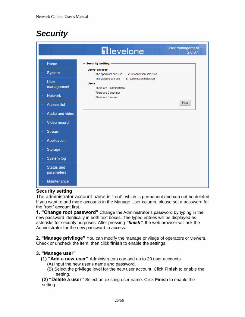
Network Camera Userrsquos Manual
2556
Security
Security setting The administrator account name is ldquorootrdquo which is permanent and can not be deleted If you want to add more accounts in the Manage User column please set a password for the ldquorootrdquo account first 1 ldquoChange root passwordrdquo Change the Administratorrsquos password by typing in the new password identically in both text boxes The typed entries will be displayed as asterisks for security purposes After pressing ldquofinishrdquo the web browser will ask the Administrator for the new password to access
2 ldquoManage privilegerdquo You can modify the manage privilege of operators or viewers Check or uncheck the item then click finish to enable the settings
3 ldquoManage userrdquo (1) ldquoAdd a new userrdquo Administrators can add up to 20 user accounts
(A) Input the new userrsquos name and password (B) Select the privilege level for the new user account Click Finish to enable the
setting
(2) ldquoDelete a userrdquo Select an existing user name Click Finish to enable the setting
Network Camera Userrsquos Manual
2656
(3) ldquoUpdate a existing userrdquo Select an existing user name Administrators can modify userrsquos password and privilege Click Finish to enable the setting
Access rights are sorted by user privilege (Administrator Operator and Viewer) Only administrators can access the Configuration page Operators cannot access the Configuration page but can use the URL Commands to get and set the value of parameters Viewers access only the main page for live viewing
Network
Any changes made on this page will restart the system in order to validate the changes Make sure every field is entered correctly before clicking on ldquofinishrdquo
Network Camera Userrsquos Manual
2756
Network Setting ldquoLANrdquo amp ldquoPPPoErdquo The default type is LAN Select PPPoE if using ADSL
1 LAN
The default status is Get IP address automatically This could be tedious to perform software installation whenever the Network Camera starts Therefore once the network is set especially for the IP address should be entered correctly Select Use fixed IP address then the Network Camera will skip installation The Network Camera will automatically restart and operate normally after a power outage You can run IP installer to check the IP address assigned to the Network Camera if the IP address is forgotten or you can use the UPnP function provided by the Network Camera (MS Windows XP provides UPnP function at My Network Place)
(1) ldquoGet IP address automaticallyrdquo (2) ldquoUse fixed IP addressrdquo
- ldquoIP addressrdquo This is necessary for network identification - ldquoSubnet maskrdquo This is used to determine if the destination is in the same subnet The default value is ldquo2552552550rdquo - ldquoDefault routerrdquo This is a gateway used to forward frames to destinations in a different subnet Invalid router setting will fail the transmission to destinations in different subnet - ldquoPrimary DNSrdquo The primary domain name server that translates hostnames into IP addresses - ldquoSecondary DNSrdquo Secondary domain name server backups the Primary DNS - ldquoEnable UPnP presentation amp port forwardingrdquo Enable UPnP ability - ldquoHttp portrdquo This can be typed besides the default Port 80 Once the port is changed the users must make sure the change for the connection is successful For instance when the Administrator changes the HTTP port of the Network Camera which IP address is 192168020 from 80 or 1025 to 65535 the users must type in the web browser ldquohttp1921680208080rdquo instead of ldquohttp192168020rdquo
- ldquoRTSP Portrdquo RTSP port can be typed besides the default Port 554 - ldquoRTP Portrdquo The RTP port can be typed besides the default Port 54
Note Please set Video RTP port in even number after default value port 54 Then
Video RTCP potAudio RTP portAudio RTCP port will automatically set the
values in ascending
- ldquoRTSP Streaming access namesrdquo The RTSP streaming currently supports video only audio only and audiovideo To use the audiovideo stream type the URL asldquortsp613012543liveNsdprdquo
2 PPPoE If using the PPPoE interface you should fill the following settings from ISP
(1) ldquoUser namerdquo The login name of PPPoE account (2) ldquoPasswordrdquo The password of PPPoE account (3) ldquoConfirm passwordrdquo Input password again for confirmation
Network Camera Userrsquos Manual
2856
DDNS Setting 1 ldquoEnable DDNSrdquo This option turns on the DDNS function
2 ldquoip-discoveryrdquo In the Register column fill in the Host name (xxxx ip-discovery) Email Key and Confirm Key then click Register After a host name has been successfully created a success message will be displayed in the DDNS Registration Result column and messaging E-mail
3 ldquo3rd party DDNSrdquo This is enable or disable 3rd party DDNS 4 ldquoProviderrdquo The provider list contains hosts that provide DDNS services Please connect to the service providerrsquos website to make sure the service charges
5 ldquoHost Namerdquo If the User wants to use DDNS service this field must be filled Please input the hostname that is registered in the DDNS server
6 ldquoUser namerdquo The Username or E-mail field is necessary for logging in the DDNS server or notify the User of the new IP address Note when this field is input as ldquoUser namerdquo the following field must be input as ldquoPasswordrdquo
7 ldquoPasswordrdquo Please input the password or key to get the DDNS service
8 ldquofinishrdquo Click on this button to save modify settings for the DDNS service
Network Camera Userrsquos Manual
2956
Access list
Access list setting 1 How to control access permission by verifying the client PCrsquos IP
address General Settings General Settings
Add a rule to configure an AllowedDenied list Click Add to add a rule
Network Camera Userrsquos Manual
3056
to AllowedDenied list There are three types of rules for user to set up ldquoSinglerdquo This rule allows the user to add an IP address to the AllowedDenied list For example
ldquoNetworkrdquo This rule allows the user to assign a network address and corresponding subnet mask to the AllowDeny List The IP address is written in the CIDR format For example
Network Camera Userrsquos Manual
3156
ldquoRangerdquo This rule allows the user to assign a range of IP addresses to the AllowDeny List This rule is only applied to IPv4 For example
Network Camera Userrsquos Manual
3256
Audio and Video setting
Network Camera Userrsquos Manual
3356
General Setting 1 ldquoColor moderdquo Select use color or monochrome video display
2 ldquoVideo orientationrdquo The orientation of video
(1) ldquoFliprdquo Vertically rotate the video
(2) ldquoMirrorrdquo Horizontally rotates the video
3 ldquoEnvironmentrdquo The orientation of video
(1) ldquoindoorrdquo This option is usually selected when the Network Camera is placed in indoor environments
(2) ldquooutdoorrdquo This option is usually selected when the Network Camera is placed in outdoor environments
4 ldquoPower freqrdquo Select 50 Hz or 60Hz power line frequency
The fluorescent light will flash according to the power line frequency that
depends on local utility Change the frequency setting to eliminate uncomfortable flash image when the light source is only fluorescent light
Video Setting 1 ldquoContrastrdquo Adjust the image contrast level which ranges from -5 to +5 The default value is set to 0
2 ldquoBrightnessrdquo Adjust the image brightness level which ranges from -5 to +5 The default value is set to 0
3 ldquoSaturationrdquo Adjust the image saturation level which ranges from -5 to +5 The default value is set to 0
4 ldquoSharpnessrdquo Adjust the image sharpness level which ranges from -5 to +5 The default value is set to 0
5 ldquoEVrdquo Exposure value represent the expected target value of the luminance of
the weighting result of AE windows in the image and its tolerance as offset
6 ldquoGainrdquo In the slide bar of Gain there are also two sliders which represent the
limitations to control the maximum gain value and the minimum one respectively Normally the minimum value is to 1x for better quality
Network Camera Userrsquos Manual
3456
Exposure setting Here it provides 3 mode Auto Backlight and Customized Auto and
Backlight modes are 2 default settings for general purpose and backlight scene
respectively
Customized mode relates to the grid window above can be pointed on for
interesting areas Within the mode Customized 1615 grids windows can be chosen to match wherewhat you are interested in Push down left-button of mouse and drag to draw the grids for interesting areas or push down right-button of mouse and drag to clean the grids for insignificant areas
ldquoTarget Luminance and Offsetrdquo
These two slide bar Target Luminance and Offset represent the expected
target value of the luminance of the weighting result of AE windows in the image and its tolerance as offset For example target luminance is set to 100 and target offset is set to 20 that means the average luminance of the AE window should be in the range from 80 to 120 (100plusmn(10 When the actual luminance does not meet this range the AE function will adjust shutter and gain to meet it as possible In some extreme cases it cannot reach the target because the environment is too bright or dark When the environment is not consistent eg with big moving objects and the offset is too narrow the AE will act more frequently that will cause the background of view inconsistent The offset value is recommended to set 15~25 of target luminance
Network Camera Userrsquos Manual
3556
ldquoGainrdquo
In the slide bar of Gain there are also two sliders which represent the limitations
to control the maximum gain value and the minimum one respectively Normally the minimum value is to 1x for better quality It is not allowed if the maximum slider and the minimum one are set to the same value without adjustable interval Besides the noise will be increased if the actual gain is too large When the max slider is dragged over sensors max gain the slide bar will become deep blue to represent it will apply Mozart 3s digital gain which extend the max gain for very low light
ldquoShutter Speedrdquo
There are 2 fields minimal and maximal time for the range of Shutter Speed
The precision of the parameter is 11000000 sec but it is NOT actual precision of the shutter speed of the sensor The actual precision of the shutter speed depends on each sensorrsquos specification Here it will be rounded to approach sensorrsquos effective exposure time To avoid flickering or banding phenomenon under fluorescent light the actual shutter speed will be locked at 1120 160
130 if Power Line Frequency is 60Hz or 1100 150 125 if Power Line
Frequency is 50Hz The setting of Power Line Frequency is on the sub-tab Video
and Audio The exposure may not be stable if the maximum value and the minimum one are set to the same value without adjustable interval Besides the frame rate will drop down if the actual shutter speed is too slow to meet expected frame rate
Noise reduction
Provides 2D and 3D features
Wide Dynamic Range Enable Wide Dynamic Range auto in different level to improve the exposure when both bright and dark areas simultaneously in the field of view of the camera The default is off
Infrared Led Setting 1 ldquoInfrared LED Controlrdquo IR led for Day and Night (Option) User can turn onoff the built-in IR led This function is very useful under low illumination environment
(1) ldquoAutordquo Select IR sensitivity from 0 to 4
(2) ldquoManualrdquo Turn onoff the IR led manually
- ldquoTurn onrdquo Turn on led - ldquoTurn offrdquo Turn off led
2 ldquoLow lux moderdquo The video quality will be improved when the camera is in low lux environment (1) ldquoDisable dark moderdquo Disable low lux mode
(2) ldquoEnable dark moderdquo Enable low lux mode
Network Camera Userrsquos Manual
3656
Video output Setting 1 ldquovideo outputrdquo Can switch between NTSC and PAL
Audio Setting 1 ldquoMuterdquo Audio mute
2 ldquoMicrophone rdquo External microphone
3 ldquoMic Volumerdquo Adjust microphone volume which ranges from 1 to 46
Video record
Schedule mode
(1) ldquoEvery dayrdquo EnableDisable every day application
(2) ldquoWeek dayrdquo EnableDisable week day application
(3)ldquoSelected dayrdquo EnableDisable selected day application
Schedule information
(1) Enter the ldquoStart timerdquo and ldquoStop timerdquo for day mode Note that the time format is [hhmm] and is expressed in 24-hour clock time By default the start and end time of day mode are set to 010000 and 235959
Network Camera Userrsquos Manual
3756
(2)ldquoSunrdquoldquoMonrdquoldquoTuerdquoldquoWedrdquoldquoThurdquoldquoFrirdquoldquoSatrdquo Select the days of the week to perform the application
(3) ldquoStart dayrdquo and ldquoStart timerdquo as the start timing the time ldquoEnd dayrdquo and ldquoEnd timerdquo as the end timing the time
(4) ldquoEnable cyclic recordingrdquo The cyclic recording function is enabled during the transaction stage when a storage space is full and the incoming streaming data is about to overwrite the previously saved videos
Record parameters (1)Source Select a stream for the recording source
(2)Recording interval Select the recording time interval
(3)Prefix file name You can setting the file name and enable or disable to add the date and time on file name
Response mode There are two choices of server types available NAS SD Card Select the item to display the detailed configuration options
(1)rdquoNASrdquo
--ldquoNAS server addressrdquo Enter IP address of the NAS server
--ldquoNAS shared directoryrdquo Enter the NAS shared directory path --ldquoWorkgrouprdquo Enter the NAS workgroup parameter --ldquoUser accountrdquo Enter the login name of the NAS account --ldquoUser passwordrdquo Enter the password of the NAS account Note Video record with the Application must be set to the same shared directory
path If you would like do detail recording settings or multi-channel recording please install bundled 64CH recording software in CD
Network Camera Userrsquos Manual
3856
Stream
Audio codec setting
(1)ldquoAudio codec typerdquo There are two choices of audio codec types
available rdquoAMRrdquo ldquoAACrdquo and rdquoG711rdquo
(2) ldquoBit raterdquo -- ldquoAMRrdquo The bit rates are selectable at the following rates
47505150590067007400795010200 and 12200
-- ldquoAACrdquo The bit rates are selectable at the following rates 8Kbps16Kbps 24Kbps and 32Kbps
-- ldquoG711rdquo pcmu and pcma
Video codec setting (1) ldquoSelect Streamrdquo The Network Camera supports ldquoStream 1rdquoand ldquoStream 2rdquo
(2) ldquoVideo codecrdquo The Network Camera supports three kind of video compression mode ldquoH264rdquo or ldquoMPEG4rdquo or ldquoMJPEGrdquo User can choose one of
Network Camera Userrsquos Manual
3956
these compression modes based on requirement or application
(3) ldquoVideo sizerdquo Click the down arrow to choose the quality of image (1920x1080 1280x1024 1280x800 640x480 320x240 176x144)
(4) ldquoConnection typerdquo User can select this button to choose the better video amp links quality (Internet mode or Intranet mode)
(5) ldquoFrame raterdquo This limits the maximal refresh frame rate per second Set the frame rate higher for a smoother video quality
(6) ldquoIntra frame periodrdquo Determine how often to plant an ldquoI framerdquo The shorter the duration the more likely you will get a better video quality but at the cost of higher network bandwidth consumption
(7) ldquoVideo Quality typerdquo Setting optimizes bandwidth utilization and video quality
-- ldquoConstant bit raterdquo User can adjust the video quality from 20 Kbps to 12 Mbps
-- ldquoFixed qualityrdquo user can select from lowest quality to get best quality according The ldquoQualityrdquo are selectable at the following rates From 1 to 20
Snapshot and time display setting Adjust the photo size specifications and choose whether to mark time on the video and photo
Network Camera Userrsquos Manual
4056
Application
Schedule mode
(1) ldquoEvery dayrdquo EnableDisable every day application
(2) ldquoWeek dayrdquo EnableDisable week day application
(3) ldquoSelected dayrdquo EnableDisable selected day application
Schedule information (1) Enter the ldquoStart timerdquo and ldquoStop timerdquo for day mode
Note that the time format is [hhmmss] and is expressed in 24-hour clock time By default the start and end time of day mode are set to 010000 and 235959
(2) ldquoSunrdquoldquoMonrdquoldquoTuerdquoldquoWedrdquoldquoThurdquoldquoFrirdquoldquoSatrdquo Select the days of the week to perform the application
(3) ldquoStart dayrdquo and ldquoStart timerdquo as the start timing the time ldquoEnd dayrdquo and ldquoEnd timerdquo as the end timing the time
Trigger mode
(1) ldquoVideo motion detectionrdquo EnableDisable video motion application (2) ldquoPeriodicallyrdquo This option allows the Network Camera to trigger
periodically for every other defined minute
Network Camera Userrsquos Manual
4156
(3) ldquoDigital inputrdquo This option allows the Network Camera to use an external digital input device or sensor as a trigger source Depending on your application there are many choices of digital input devices on the market which helps to detect changes in temperature vibration sound and light etc
parameters
(1) ldquoMotion parametersrdquo Higher sensitivity and small threshold will allow easier motion detection
(2) ldquoPeriod parametersrdquo This option allows the Network Camera to trigger periodically for every other defined seconds Up to 999 seconds are allowed
(3) ldquoDigital input parametersrdquo Select the digital input type and set trigger time
Media mode There are four choices of media types available ldquoSnapshotrdquo ldquoMessagerdquo ldquoRecord(Motion Detection only)rdquo and ldquoSystem logrdquo
Snapshot amp Record file setting You can setting the file name and enable or disable to add the date and time on file name Can setting the digital output duration seconds Response mode There are four choices of server types available Email FTP NAS and SD Card storage Select the item to display the detailed configuration options
(1)ldquoEmailrdquo -- ldquoEmail security moderdquo If your SMTP server requires a secure connection (SSL or TLS) check This server requires a secure connection (SSL or TLS) -- ldquoSender emailrdquo address Enter the email address of the sender -- ldquoRecipient emailrdquo address Enter the email address of the recipient
-- ldquoServer addressrdquo Enter the domain name or IP address of the email server
--ldquoUser namerdquo Enter the user name of the email account if necessary
--ldquoPasswordrdquo Enter the password of the email account if necessary
--ldquoServer portrdquo The default mail server port is set to 25 You can also manually set another port
(2)rdquoFTPrdquo -- ldquoServer addressrdquo Enter the domain name or IP address of the FTP server
-- ldquoServer portrdquo By default the FTP server port is set to 21
-- ldquoUser namerdquo Enter the login name of the FTP account
-- ldquoPasswordrdquo Enter the password of the FTP account
-- ldquoFTP folder namerdquo Enter the folder where the media file will be placed If the folder name does not exist the Network Camera will create one on the FTP server
(3)rdquoHTTP rdquo
-- ldquoURLrdquo Enter the URL of the HTTP server
-- ldquoUser accountrdquo Enter the user name if necessary -- ldquoUser passwordrdquo Enter the password if necessary
(4)rdquoNASrdquo --ldquoNAS server addressrdquo Enter IP address of the NAS server
--ldquoNAS shared directoryrdquo Enter the NAS shared directory path
Network Camera Userrsquos Manual
4256
--ldquoWorkgrouprdquo Enter the NAS workgroup parameter --ldquoUser accountrdquo Enter the login name of the NAS account --ldquoUser passwordrdquo Enter the password of the NAS account Note Video record with the Application must be set to the same shared directory
path If you would like do detail recording settings or multi-channel recording please install bundled 64CH recording software in CD
Network Camera Userrsquos Manual
4356
Storage
Manage the storage device
S torage Status Here show the storage device information
NAS server setting
1
2
3
Network Camera Userrsquos Manual
4456
(1) ldquoNAS Host namerdquo Choose and input the NAS Host name of this camera
(2) ldquoWorkgrouprdquo Input the name of Workgroup You can see the NAS Host name you input in the same workgroup with your PC Then you can connect to this device and download the files easily from SD card which is inserted to this camera
File operation Move the mouse over the file Press the mouse right button that Right-click menu is displayed You can delete files Move the mouse over the directory Press the mouse left button that the file structure expand Press the mouse right button that Right-click menu is displayed You can choose upload or delete files NOTEAllow the user to upload or delete files when the storage device is not write-
protected If the SD card canrsquot be detected please link to the following URL httpwwwsdcardorgconsumersformatter to download the ldquoSD Formatter Kitrdquo formatting your SD card
Network Camera Userrsquos Manual
4556
Syslog
The Network camera supports log the system messages on remote server The protocol is compliant to RFC 3164 If you have external Linux server with sys log service use ldquo-rrdquo option to turn on the facility for receiving log from remote machine Or you can use some software on Windows that is compliant to RFC 3164 An example is Kiwi Syslog Daemon Visit httpwwwkiwisyslogcomkiwi-syslog-daemon-overview Check ldquoSetuprdquo and ldquoEnablerdquo then input the ldquoIP addressrdquo and ldquoportrdquo number of the log server to enable the remote log facility In the ldquoCurrent logrdquo it displays the current system log file The content of the log provides useful information about configuration and connection after system boot- up
ldquofinishrdquo Click on this button to save modify settings
Network Camera Userrsquos Manual
4656
Status and Parameters
User can find a lot of information about the system such as ldquoUpnp port forwardingrdquo
ldquoTraversing NATrdquo ldquoPublic IPrdquo and so on User also can get the number of current viewer of the Network Camera here
Network Camera Userrsquos Manual
4756
Maintenance
1 ldquoReboot systemrdquo The ldquoRebootrdquo button will reboot the Network Camera Itrsquos useful while the Network Camera got problem 2 ldquoRestore systemrdquo Click on ldquoRestorerdquo button on the configuration page to restore the factory default settings Restore all settings to factory default except settings in ldquoNetwork type rdquo and ldquoRoot Passwordrdquo The system will restart and require the installer program to set up the network again
3 ldquoCalibraterdquo Recalibrate the auto focus position to the default range to recover the tolerance caused by some external forces 4 ldquoExportImport filerdquo -- Export setting backup file Click to export all parameters for the device and user-defined scripts
-- Upload setting backup file Click Browsehellip to upload a setting backup file Please note that the model and firmware version of the device should be the same as the setting backup file If you have set up a fixed IP or other special settings for your device it is not suggested to upload a settings backup file
4 ldquoUpgrade firmwarerdquo Select the firmware file and click upgrade button Please be aware that you should not turn off the power during updating the firmware and wait for finish message
Network Camera Userrsquos Manual
4856
Warning The upgrade firmware procedure cannot be interrupted If the power
andor network connection are broken during the procedure it might possibly cause serious damage to the Network Camera
Note When upgrade firmware please wait for 120~210 seconds and then you can connect to Network Camera again The system will restart and require the installer program to set up the network again
Network Camera Userrsquos Manual
4956
Appendix
A Troubleshooting amp Frequently Asked Questions Q1 Status led does not light up
A1 First make sure that「ConfigurationgtSystemgtTurn off the LED indicator」is disabled
If it is check the item and the led should light up Second if red led does not light up please check that the power adapter in the package is plugged correctly And last if green led does not light up please check that category 5 UTP cable is plugged correctly If the problem is still not solved please contact your dealer for further help
Q2 What kind of Ethernet cable is used by network camera
A2 The network Camera uses Category 5 UTP cable allowing 10 andor 100 Base-T networking
Q3 The Network Camera will be installed and work if a firewall exists on
the network
A3 There are two way to set up the IP camera at Internet (1) By UPnP Port Forwarding 1 Select an IP router It must support UPnP port forwarding and enable this function
first
2 Connect camera RJ45 cable to IP router and the router is also connected to Internet
3 Plug power cord to camera
4 Go to camera Network page Enable UPnP port forwarding
5 Check camera status we can see the ports had been successfully opened
Network Camera Userrsquos Manual
5056
6Type IP address8080 at browser Then you can see camera through Internet
7You can also type the ddns name at below label of camera on browser URL field For example you may type ah00001ip-discoverycom8080 (2) By Setting Port Forwarding Manually 1 Select a router Set the port forwarding as following
Network Camera Userrsquos Manual
5156
PS Port 80 is HTTP Port port 53 is stream port port 554 is RTSP port and port 443 is HTTPS port 2Go to camera Network page Disable UPnP port forwarding function
Network Camera Userrsquos Manual
5256
3 Type IP address at browser Then you can see camera through Internet
4 You can also type the ddns name at below label of camera on browser URL field For example you may type ah00001ip-discoverycom
Note The firewall software at PC may block the transfer of network camera Please remove or stop the kind software
Q4 How can I find the network camera in the local area network
A4 By using the IP Finder2 program or using UPnP to find it
Q5 IP Finder2 program cannot find Network Camera in the local area
network at first time
A5 Make sure the subnet of network camera is same as your PC If the local area network supports DHCP the camera is ldquoGet IP address automaticallyrdquo in the ldquoNetworkrdquo page default If the local area network does not support DHCP change your PC IP address to ldquo1921680xxxrdquo
Network Camera Userrsquos Manual
5356
Q6 How can I restore the network camera to default value
A6 Use a gem clip to press on the inside button Network camera begins to restore default value You can also press the button ldquoFactoryrdquo in ldquoMaintenancerdquo page to restore the default value
Q7 I cannot play the recorded video file
A7 Install the audio codec in the CD and use the Windows Media Player 10 or later to play the ASF or AVI file recorded by the network camera
Q8 Infrared led does not light up
A8 Check「ConfigurationgtAudio and VideogtInfrared LED Control」 is ldquoAutordquo or
ldquoManual》Turn onrdquo
Q9 The network camera cannot focus accurately
A9 (1) The lens is dirty or dust is attached Clean the lens with lens cleaner And then adjust the camera focus manually (2) The image may be out of focus If the object is too near move the object away from Network Camera
Q10 The cover of network camera is warm Is it normal
A10 Network camera is a precision device The internal material has the operational temperature and it is normal when user touch the cover feels warm It is recommended to put the network camera at aired place and not put at any other device
Q11 The process of upgrade firmware abort
A11 Contact your dealer for further help
Q12 Cannot access the login page and other web pages of Network
Network Camera Userrsquos Manual
5456
Camera from Internet Explorer
A12 bull May be due to the network cable Try correcting your network cable and configuration Test the network interface by connecting a local computer to the Network Camera via a crossover cable bull Make sure the Internet connection and setting is ok bull Make sure enter the IP address of Internet Explorer is correct If Network Camera has a dynamic address it may have changed since you last checked it bull Network congestion may prevent the web page appearing quickly Wait for a while The IP address and Subnet Mask of the PC and Network Camera must be in the same class of the private IP address on the LAN bull Make sure the http port used by the Network Camera default=80 is forward to the Network Camerarsquos private IP address bull The port number assigned in your Network Camera might not be available via Internet Check your ISP for available port bull The proxy server may prevent you from connecting directly to Network Camera set up not to use the proxy server bull Confirm that Default Gateway address is correct bull The router needs Port Forwarding feature Refer to your routers manual for details bull Packet Filtering of the router may prohibit access from an external network Refer to your routers manual for details bull Access Network Camera from the Internet with the global IP address of the router and port number of Network Camera bull Some routers reject the global IP address to access Network Camera on the same LAN Access with the private IP address and correct port number of Network Camera bull When you use DDNS you need to set Default Gateway and DNS server address bull If itrsquos not working after above procedure reset Network Camera to default setting and installed it again bull Maybe the IP Address of the Network Camera is already being used by another device or computer bull If the problem is not solved the Network Camera might be faulty Contact your dealer for further help
Network Camera Userrsquos Manual
5556
B Technical specifications
- System RAM 4G bit DDRⅢ
ROM 16MB Flash ROM
- Camera specification 127 inch color CMOS sensor Resolution 1920x1080 10LuxF20 AGC AWB AEC
- Infrared Led High power IR Leds 25~30 M visible AutoManual mode
- Lens 3X optical zoom lens auto iris auto focus f = 28~ 12mm F18 Fov(D) 136deg ~ 39deg
- Protocol TCPIP HTTPUDP SMTP FTP DDNS UPnP Telnet NTP PPPoE RTSP RTPRTCPDHCP and DNS
- Video Resolution Up to 30 frames at 176x144 Up to 30 frames at 320x240 Up to 30 frames at 640x480 Up to 30 frames at 1280x800 Up to 30 frames at 1280x1024 Up to 30 frames at 1920x1080
- Algorithm supported H264MPEG4MJPEG dual codec for streaming video JPEG for still image
- Audio AMRAACG711 External MIC input 2-way audio
- Physical 10 baseT100 baseT and 1000 baseT Fast
Ethernet auto negotiation
- Power Input 100-240VAC 5060Hz 07A Output 12VDC 15A Consumption Max 12 W Support 8023af compliant Power over Ethernet
- EMI amp Safety CE FCC
- Dimension Length 165mm Diameter 75mm
- Operating Environment Temperature -20 ~ 50
Humidity 85 RH
- Weight NET 600g With bracket 800g
Network Camera Userrsquos Manual
5656
Notification of Compliance Appendix C
Europe - EU Declaration of Conformity
For complete DoC please visit httpgloballevel1comdownloadsphpaction=init
GPL License Agreement GPL may be included in this product to view the GPL license agreement goes to httpdownloadlevel1comlevel1gplGPLpdf For GNU General Public License (GPL) related information please visit httpgloballevel1comdownloadsphpaction=init
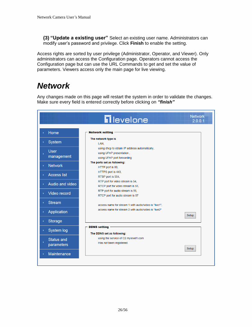
Network Camera Userrsquos Manual
3056
to AllowedDenied list There are three types of rules for user to set up ldquoSinglerdquo This rule allows the user to add an IP address to the AllowedDenied list For example
ldquoNetworkrdquo This rule allows the user to assign a network address and corresponding subnet mask to the AllowDeny List The IP address is written in the CIDR format For example
Network Camera Userrsquos Manual
3156
ldquoRangerdquo This rule allows the user to assign a range of IP addresses to the AllowDeny List This rule is only applied to IPv4 For example
Network Camera Userrsquos Manual
3256
Audio and Video setting
Network Camera Userrsquos Manual
3356
General Setting 1 ldquoColor moderdquo Select use color or monochrome video display
2 ldquoVideo orientationrdquo The orientation of video
(1) ldquoFliprdquo Vertically rotate the video
(2) ldquoMirrorrdquo Horizontally rotates the video
3 ldquoEnvironmentrdquo The orientation of video
(1) ldquoindoorrdquo This option is usually selected when the Network Camera is placed in indoor environments
(2) ldquooutdoorrdquo This option is usually selected when the Network Camera is placed in outdoor environments
4 ldquoPower freqrdquo Select 50 Hz or 60Hz power line frequency
The fluorescent light will flash according to the power line frequency that
depends on local utility Change the frequency setting to eliminate uncomfortable flash image when the light source is only fluorescent light
Video Setting 1 ldquoContrastrdquo Adjust the image contrast level which ranges from -5 to +5 The default value is set to 0
2 ldquoBrightnessrdquo Adjust the image brightness level which ranges from -5 to +5 The default value is set to 0
3 ldquoSaturationrdquo Adjust the image saturation level which ranges from -5 to +5 The default value is set to 0
4 ldquoSharpnessrdquo Adjust the image sharpness level which ranges from -5 to +5 The default value is set to 0
5 ldquoEVrdquo Exposure value represent the expected target value of the luminance of
the weighting result of AE windows in the image and its tolerance as offset
6 ldquoGainrdquo In the slide bar of Gain there are also two sliders which represent the
limitations to control the maximum gain value and the minimum one respectively Normally the minimum value is to 1x for better quality
Network Camera Userrsquos Manual
3456
Exposure setting Here it provides 3 mode Auto Backlight and Customized Auto and
Backlight modes are 2 default settings for general purpose and backlight scene
respectively
Customized mode relates to the grid window above can be pointed on for
interesting areas Within the mode Customized 1615 grids windows can be chosen to match wherewhat you are interested in Push down left-button of mouse and drag to draw the grids for interesting areas or push down right-button of mouse and drag to clean the grids for insignificant areas
ldquoTarget Luminance and Offsetrdquo
These two slide bar Target Luminance and Offset represent the expected
target value of the luminance of the weighting result of AE windows in the image and its tolerance as offset For example target luminance is set to 100 and target offset is set to 20 that means the average luminance of the AE window should be in the range from 80 to 120 (100plusmn(10 When the actual luminance does not meet this range the AE function will adjust shutter and gain to meet it as possible In some extreme cases it cannot reach the target because the environment is too bright or dark When the environment is not consistent eg with big moving objects and the offset is too narrow the AE will act more frequently that will cause the background of view inconsistent The offset value is recommended to set 15~25 of target luminance
Network Camera Userrsquos Manual
3556
ldquoGainrdquo
In the slide bar of Gain there are also two sliders which represent the limitations
to control the maximum gain value and the minimum one respectively Normally the minimum value is to 1x for better quality It is not allowed if the maximum slider and the minimum one are set to the same value without adjustable interval Besides the noise will be increased if the actual gain is too large When the max slider is dragged over sensors max gain the slide bar will become deep blue to represent it will apply Mozart 3s digital gain which extend the max gain for very low light
ldquoShutter Speedrdquo
There are 2 fields minimal and maximal time for the range of Shutter Speed
The precision of the parameter is 11000000 sec but it is NOT actual precision of the shutter speed of the sensor The actual precision of the shutter speed depends on each sensorrsquos specification Here it will be rounded to approach sensorrsquos effective exposure time To avoid flickering or banding phenomenon under fluorescent light the actual shutter speed will be locked at 1120 160
130 if Power Line Frequency is 60Hz or 1100 150 125 if Power Line
Frequency is 50Hz The setting of Power Line Frequency is on the sub-tab Video
and Audio The exposure may not be stable if the maximum value and the minimum one are set to the same value without adjustable interval Besides the frame rate will drop down if the actual shutter speed is too slow to meet expected frame rate
Noise reduction
Provides 2D and 3D features
Wide Dynamic Range Enable Wide Dynamic Range auto in different level to improve the exposure when both bright and dark areas simultaneously in the field of view of the camera The default is off
Infrared Led Setting 1 ldquoInfrared LED Controlrdquo IR led for Day and Night (Option) User can turn onoff the built-in IR led This function is very useful under low illumination environment
(1) ldquoAutordquo Select IR sensitivity from 0 to 4
(2) ldquoManualrdquo Turn onoff the IR led manually
- ldquoTurn onrdquo Turn on led - ldquoTurn offrdquo Turn off led
2 ldquoLow lux moderdquo The video quality will be improved when the camera is in low lux environment (1) ldquoDisable dark moderdquo Disable low lux mode
(2) ldquoEnable dark moderdquo Enable low lux mode
Network Camera Userrsquos Manual
3656
Video output Setting 1 ldquovideo outputrdquo Can switch between NTSC and PAL
Audio Setting 1 ldquoMuterdquo Audio mute
2 ldquoMicrophone rdquo External microphone
3 ldquoMic Volumerdquo Adjust microphone volume which ranges from 1 to 46
Video record
Schedule mode
(1) ldquoEvery dayrdquo EnableDisable every day application
(2) ldquoWeek dayrdquo EnableDisable week day application
(3)ldquoSelected dayrdquo EnableDisable selected day application
Schedule information
(1) Enter the ldquoStart timerdquo and ldquoStop timerdquo for day mode Note that the time format is [hhmm] and is expressed in 24-hour clock time By default the start and end time of day mode are set to 010000 and 235959
Network Camera Userrsquos Manual
3756
(2)ldquoSunrdquoldquoMonrdquoldquoTuerdquoldquoWedrdquoldquoThurdquoldquoFrirdquoldquoSatrdquo Select the days of the week to perform the application
(3) ldquoStart dayrdquo and ldquoStart timerdquo as the start timing the time ldquoEnd dayrdquo and ldquoEnd timerdquo as the end timing the time
(4) ldquoEnable cyclic recordingrdquo The cyclic recording function is enabled during the transaction stage when a storage space is full and the incoming streaming data is about to overwrite the previously saved videos
Record parameters (1)Source Select a stream for the recording source
(2)Recording interval Select the recording time interval
(3)Prefix file name You can setting the file name and enable or disable to add the date and time on file name
Response mode There are two choices of server types available NAS SD Card Select the item to display the detailed configuration options
(1)rdquoNASrdquo
--ldquoNAS server addressrdquo Enter IP address of the NAS server
--ldquoNAS shared directoryrdquo Enter the NAS shared directory path --ldquoWorkgrouprdquo Enter the NAS workgroup parameter --ldquoUser accountrdquo Enter the login name of the NAS account --ldquoUser passwordrdquo Enter the password of the NAS account Note Video record with the Application must be set to the same shared directory
path If you would like do detail recording settings or multi-channel recording please install bundled 64CH recording software in CD
Network Camera Userrsquos Manual
3856
Stream
Audio codec setting
(1)ldquoAudio codec typerdquo There are two choices of audio codec types
available rdquoAMRrdquo ldquoAACrdquo and rdquoG711rdquo
(2) ldquoBit raterdquo -- ldquoAMRrdquo The bit rates are selectable at the following rates
47505150590067007400795010200 and 12200
-- ldquoAACrdquo The bit rates are selectable at the following rates 8Kbps16Kbps 24Kbps and 32Kbps
-- ldquoG711rdquo pcmu and pcma
Video codec setting (1) ldquoSelect Streamrdquo The Network Camera supports ldquoStream 1rdquoand ldquoStream 2rdquo
(2) ldquoVideo codecrdquo The Network Camera supports three kind of video compression mode ldquoH264rdquo or ldquoMPEG4rdquo or ldquoMJPEGrdquo User can choose one of
Network Camera Userrsquos Manual
3956
these compression modes based on requirement or application
(3) ldquoVideo sizerdquo Click the down arrow to choose the quality of image (1920x1080 1280x1024 1280x800 640x480 320x240 176x144)
(4) ldquoConnection typerdquo User can select this button to choose the better video amp links quality (Internet mode or Intranet mode)
(5) ldquoFrame raterdquo This limits the maximal refresh frame rate per second Set the frame rate higher for a smoother video quality
(6) ldquoIntra frame periodrdquo Determine how often to plant an ldquoI framerdquo The shorter the duration the more likely you will get a better video quality but at the cost of higher network bandwidth consumption
(7) ldquoVideo Quality typerdquo Setting optimizes bandwidth utilization and video quality
-- ldquoConstant bit raterdquo User can adjust the video quality from 20 Kbps to 12 Mbps
-- ldquoFixed qualityrdquo user can select from lowest quality to get best quality according The ldquoQualityrdquo are selectable at the following rates From 1 to 20
Snapshot and time display setting Adjust the photo size specifications and choose whether to mark time on the video and photo
Network Camera Userrsquos Manual
4056
Application
Schedule mode
(1) ldquoEvery dayrdquo EnableDisable every day application
(2) ldquoWeek dayrdquo EnableDisable week day application
(3) ldquoSelected dayrdquo EnableDisable selected day application
Schedule information (1) Enter the ldquoStart timerdquo and ldquoStop timerdquo for day mode
Note that the time format is [hhmmss] and is expressed in 24-hour clock time By default the start and end time of day mode are set to 010000 and 235959
(2) ldquoSunrdquoldquoMonrdquoldquoTuerdquoldquoWedrdquoldquoThurdquoldquoFrirdquoldquoSatrdquo Select the days of the week to perform the application
(3) ldquoStart dayrdquo and ldquoStart timerdquo as the start timing the time ldquoEnd dayrdquo and ldquoEnd timerdquo as the end timing the time
Trigger mode
(1) ldquoVideo motion detectionrdquo EnableDisable video motion application (2) ldquoPeriodicallyrdquo This option allows the Network Camera to trigger
periodically for every other defined minute
Network Camera Userrsquos Manual
4156
(3) ldquoDigital inputrdquo This option allows the Network Camera to use an external digital input device or sensor as a trigger source Depending on your application there are many choices of digital input devices on the market which helps to detect changes in temperature vibration sound and light etc
parameters
(1) ldquoMotion parametersrdquo Higher sensitivity and small threshold will allow easier motion detection
(2) ldquoPeriod parametersrdquo This option allows the Network Camera to trigger periodically for every other defined seconds Up to 999 seconds are allowed
(3) ldquoDigital input parametersrdquo Select the digital input type and set trigger time
Media mode There are four choices of media types available ldquoSnapshotrdquo ldquoMessagerdquo ldquoRecord(Motion Detection only)rdquo and ldquoSystem logrdquo
Snapshot amp Record file setting You can setting the file name and enable or disable to add the date and time on file name Can setting the digital output duration seconds Response mode There are four choices of server types available Email FTP NAS and SD Card storage Select the item to display the detailed configuration options
(1)ldquoEmailrdquo -- ldquoEmail security moderdquo If your SMTP server requires a secure connection (SSL or TLS) check This server requires a secure connection (SSL or TLS) -- ldquoSender emailrdquo address Enter the email address of the sender -- ldquoRecipient emailrdquo address Enter the email address of the recipient
-- ldquoServer addressrdquo Enter the domain name or IP address of the email server
--ldquoUser namerdquo Enter the user name of the email account if necessary
--ldquoPasswordrdquo Enter the password of the email account if necessary
--ldquoServer portrdquo The default mail server port is set to 25 You can also manually set another port
(2)rdquoFTPrdquo -- ldquoServer addressrdquo Enter the domain name or IP address of the FTP server
-- ldquoServer portrdquo By default the FTP server port is set to 21
-- ldquoUser namerdquo Enter the login name of the FTP account
-- ldquoPasswordrdquo Enter the password of the FTP account
-- ldquoFTP folder namerdquo Enter the folder where the media file will be placed If the folder name does not exist the Network Camera will create one on the FTP server
(3)rdquoHTTP rdquo
-- ldquoURLrdquo Enter the URL of the HTTP server
-- ldquoUser accountrdquo Enter the user name if necessary -- ldquoUser passwordrdquo Enter the password if necessary
(4)rdquoNASrdquo --ldquoNAS server addressrdquo Enter IP address of the NAS server
--ldquoNAS shared directoryrdquo Enter the NAS shared directory path
Network Camera Userrsquos Manual
4256
--ldquoWorkgrouprdquo Enter the NAS workgroup parameter --ldquoUser accountrdquo Enter the login name of the NAS account --ldquoUser passwordrdquo Enter the password of the NAS account Note Video record with the Application must be set to the same shared directory
path If you would like do detail recording settings or multi-channel recording please install bundled 64CH recording software in CD
Network Camera Userrsquos Manual
4356
Storage
Manage the storage device
S torage Status Here show the storage device information
NAS server setting
1
2
3
Network Camera Userrsquos Manual
4456
(1) ldquoNAS Host namerdquo Choose and input the NAS Host name of this camera
(2) ldquoWorkgrouprdquo Input the name of Workgroup You can see the NAS Host name you input in the same workgroup with your PC Then you can connect to this device and download the files easily from SD card which is inserted to this camera
File operation Move the mouse over the file Press the mouse right button that Right-click menu is displayed You can delete files Move the mouse over the directory Press the mouse left button that the file structure expand Press the mouse right button that Right-click menu is displayed You can choose upload or delete files NOTEAllow the user to upload or delete files when the storage device is not write-
protected If the SD card canrsquot be detected please link to the following URL httpwwwsdcardorgconsumersformatter to download the ldquoSD Formatter Kitrdquo formatting your SD card
Network Camera Userrsquos Manual
4556
Syslog
The Network camera supports log the system messages on remote server The protocol is compliant to RFC 3164 If you have external Linux server with sys log service use ldquo-rrdquo option to turn on the facility for receiving log from remote machine Or you can use some software on Windows that is compliant to RFC 3164 An example is Kiwi Syslog Daemon Visit httpwwwkiwisyslogcomkiwi-syslog-daemon-overview Check ldquoSetuprdquo and ldquoEnablerdquo then input the ldquoIP addressrdquo and ldquoportrdquo number of the log server to enable the remote log facility In the ldquoCurrent logrdquo it displays the current system log file The content of the log provides useful information about configuration and connection after system boot- up
ldquofinishrdquo Click on this button to save modify settings
Network Camera Userrsquos Manual
4656
Status and Parameters
User can find a lot of information about the system such as ldquoUpnp port forwardingrdquo
ldquoTraversing NATrdquo ldquoPublic IPrdquo and so on User also can get the number of current viewer of the Network Camera here
Network Camera Userrsquos Manual
4756
Maintenance
1 ldquoReboot systemrdquo The ldquoRebootrdquo button will reboot the Network Camera Itrsquos useful while the Network Camera got problem 2 ldquoRestore systemrdquo Click on ldquoRestorerdquo button on the configuration page to restore the factory default settings Restore all settings to factory default except settings in ldquoNetwork type rdquo and ldquoRoot Passwordrdquo The system will restart and require the installer program to set up the network again
3 ldquoCalibraterdquo Recalibrate the auto focus position to the default range to recover the tolerance caused by some external forces 4 ldquoExportImport filerdquo -- Export setting backup file Click to export all parameters for the device and user-defined scripts
-- Upload setting backup file Click Browsehellip to upload a setting backup file Please note that the model and firmware version of the device should be the same as the setting backup file If you have set up a fixed IP or other special settings for your device it is not suggested to upload a settings backup file
4 ldquoUpgrade firmwarerdquo Select the firmware file and click upgrade button Please be aware that you should not turn off the power during updating the firmware and wait for finish message
Network Camera Userrsquos Manual
4856
Warning The upgrade firmware procedure cannot be interrupted If the power
andor network connection are broken during the procedure it might possibly cause serious damage to the Network Camera
Note When upgrade firmware please wait for 120~210 seconds and then you can connect to Network Camera again The system will restart and require the installer program to set up the network again
Network Camera Userrsquos Manual
4956
Appendix
A Troubleshooting amp Frequently Asked Questions Q1 Status led does not light up
A1 First make sure that「ConfigurationgtSystemgtTurn off the LED indicator」is disabled
If it is check the item and the led should light up Second if red led does not light up please check that the power adapter in the package is plugged correctly And last if green led does not light up please check that category 5 UTP cable is plugged correctly If the problem is still not solved please contact your dealer for further help
Q2 What kind of Ethernet cable is used by network camera
A2 The network Camera uses Category 5 UTP cable allowing 10 andor 100 Base-T networking
Q3 The Network Camera will be installed and work if a firewall exists on
the network
A3 There are two way to set up the IP camera at Internet (1) By UPnP Port Forwarding 1 Select an IP router It must support UPnP port forwarding and enable this function
first
2 Connect camera RJ45 cable to IP router and the router is also connected to Internet
3 Plug power cord to camera
4 Go to camera Network page Enable UPnP port forwarding
5 Check camera status we can see the ports had been successfully opened
Network Camera Userrsquos Manual
5056
6Type IP address8080 at browser Then you can see camera through Internet
7You can also type the ddns name at below label of camera on browser URL field For example you may type ah00001ip-discoverycom8080 (2) By Setting Port Forwarding Manually 1 Select a router Set the port forwarding as following
Network Camera Userrsquos Manual
5156
PS Port 80 is HTTP Port port 53 is stream port port 554 is RTSP port and port 443 is HTTPS port 2Go to camera Network page Disable UPnP port forwarding function
Network Camera Userrsquos Manual
5256
3 Type IP address at browser Then you can see camera through Internet
4 You can also type the ddns name at below label of camera on browser URL field For example you may type ah00001ip-discoverycom
Note The firewall software at PC may block the transfer of network camera Please remove or stop the kind software
Q4 How can I find the network camera in the local area network
A4 By using the IP Finder2 program or using UPnP to find it
Q5 IP Finder2 program cannot find Network Camera in the local area
network at first time
A5 Make sure the subnet of network camera is same as your PC If the local area network supports DHCP the camera is ldquoGet IP address automaticallyrdquo in the ldquoNetworkrdquo page default If the local area network does not support DHCP change your PC IP address to ldquo1921680xxxrdquo
Network Camera Userrsquos Manual
5356
Q6 How can I restore the network camera to default value
A6 Use a gem clip to press on the inside button Network camera begins to restore default value You can also press the button ldquoFactoryrdquo in ldquoMaintenancerdquo page to restore the default value
Q7 I cannot play the recorded video file
A7 Install the audio codec in the CD and use the Windows Media Player 10 or later to play the ASF or AVI file recorded by the network camera
Q8 Infrared led does not light up
A8 Check「ConfigurationgtAudio and VideogtInfrared LED Control」 is ldquoAutordquo or
ldquoManual》Turn onrdquo
Q9 The network camera cannot focus accurately
A9 (1) The lens is dirty or dust is attached Clean the lens with lens cleaner And then adjust the camera focus manually (2) The image may be out of focus If the object is too near move the object away from Network Camera
Q10 The cover of network camera is warm Is it normal
A10 Network camera is a precision device The internal material has the operational temperature and it is normal when user touch the cover feels warm It is recommended to put the network camera at aired place and not put at any other device
Q11 The process of upgrade firmware abort
A11 Contact your dealer for further help
Q12 Cannot access the login page and other web pages of Network
Network Camera Userrsquos Manual
5456
Camera from Internet Explorer
A12 bull May be due to the network cable Try correcting your network cable and configuration Test the network interface by connecting a local computer to the Network Camera via a crossover cable bull Make sure the Internet connection and setting is ok bull Make sure enter the IP address of Internet Explorer is correct If Network Camera has a dynamic address it may have changed since you last checked it bull Network congestion may prevent the web page appearing quickly Wait for a while The IP address and Subnet Mask of the PC and Network Camera must be in the same class of the private IP address on the LAN bull Make sure the http port used by the Network Camera default=80 is forward to the Network Camerarsquos private IP address bull The port number assigned in your Network Camera might not be available via Internet Check your ISP for available port bull The proxy server may prevent you from connecting directly to Network Camera set up not to use the proxy server bull Confirm that Default Gateway address is correct bull The router needs Port Forwarding feature Refer to your routers manual for details bull Packet Filtering of the router may prohibit access from an external network Refer to your routers manual for details bull Access Network Camera from the Internet with the global IP address of the router and port number of Network Camera bull Some routers reject the global IP address to access Network Camera on the same LAN Access with the private IP address and correct port number of Network Camera bull When you use DDNS you need to set Default Gateway and DNS server address bull If itrsquos not working after above procedure reset Network Camera to default setting and installed it again bull Maybe the IP Address of the Network Camera is already being used by another device or computer bull If the problem is not solved the Network Camera might be faulty Contact your dealer for further help
Network Camera Userrsquos Manual
5556
B Technical specifications
- System RAM 4G bit DDRⅢ
ROM 16MB Flash ROM
- Camera specification 127 inch color CMOS sensor Resolution 1920x1080 10LuxF20 AGC AWB AEC
- Infrared Led High power IR Leds 25~30 M visible AutoManual mode
- Lens 3X optical zoom lens auto iris auto focus f = 28~ 12mm F18 Fov(D) 136deg ~ 39deg
- Protocol TCPIP HTTPUDP SMTP FTP DDNS UPnP Telnet NTP PPPoE RTSP RTPRTCPDHCP and DNS
- Video Resolution Up to 30 frames at 176x144 Up to 30 frames at 320x240 Up to 30 frames at 640x480 Up to 30 frames at 1280x800 Up to 30 frames at 1280x1024 Up to 30 frames at 1920x1080
- Algorithm supported H264MPEG4MJPEG dual codec for streaming video JPEG for still image
- Audio AMRAACG711 External MIC input 2-way audio
- Physical 10 baseT100 baseT and 1000 baseT Fast
Ethernet auto negotiation
- Power Input 100-240VAC 5060Hz 07A Output 12VDC 15A Consumption Max 12 W Support 8023af compliant Power over Ethernet
- EMI amp Safety CE FCC
- Dimension Length 165mm Diameter 75mm
- Operating Environment Temperature -20 ~ 50
Humidity 85 RH
- Weight NET 600g With bracket 800g
Network Camera Userrsquos Manual
5656
Notification of Compliance Appendix C
Europe - EU Declaration of Conformity
For complete DoC please visit httpgloballevel1comdownloadsphpaction=init
GPL License Agreement GPL may be included in this product to view the GPL license agreement goes to httpdownloadlevel1comlevel1gplGPLpdf For GNU General Public License (GPL) related information please visit httpgloballevel1comdownloadsphpaction=init
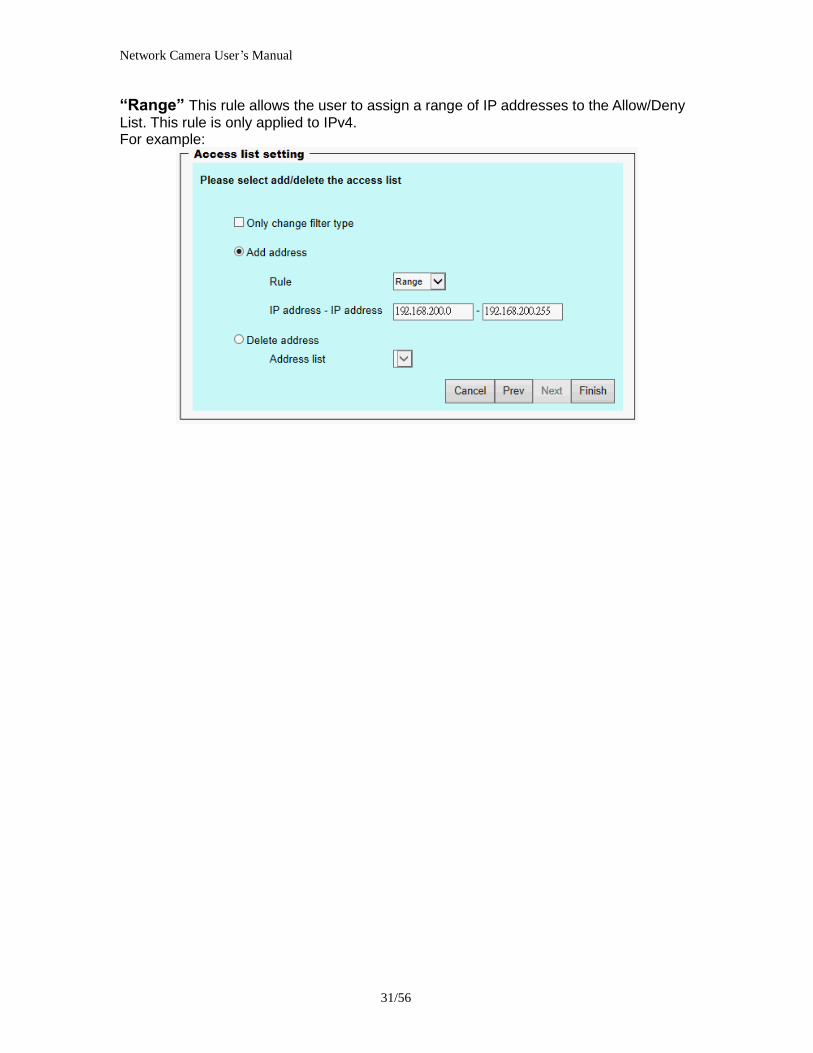
Network Camera Userrsquos Manual
3256
Audio and Video setting
Network Camera Userrsquos Manual
3356
General Setting 1 ldquoColor moderdquo Select use color or monochrome video display
2 ldquoVideo orientationrdquo The orientation of video
(1) ldquoFliprdquo Vertically rotate the video
(2) ldquoMirrorrdquo Horizontally rotates the video
3 ldquoEnvironmentrdquo The orientation of video
(1) ldquoindoorrdquo This option is usually selected when the Network Camera is placed in indoor environments
(2) ldquooutdoorrdquo This option is usually selected when the Network Camera is placed in outdoor environments
4 ldquoPower freqrdquo Select 50 Hz or 60Hz power line frequency
The fluorescent light will flash according to the power line frequency that
depends on local utility Change the frequency setting to eliminate uncomfortable flash image when the light source is only fluorescent light
Video Setting 1 ldquoContrastrdquo Adjust the image contrast level which ranges from -5 to +5 The default value is set to 0
2 ldquoBrightnessrdquo Adjust the image brightness level which ranges from -5 to +5 The default value is set to 0
3 ldquoSaturationrdquo Adjust the image saturation level which ranges from -5 to +5 The default value is set to 0
4 ldquoSharpnessrdquo Adjust the image sharpness level which ranges from -5 to +5 The default value is set to 0
5 ldquoEVrdquo Exposure value represent the expected target value of the luminance of
the weighting result of AE windows in the image and its tolerance as offset
6 ldquoGainrdquo In the slide bar of Gain there are also two sliders which represent the
limitations to control the maximum gain value and the minimum one respectively Normally the minimum value is to 1x for better quality
Network Camera Userrsquos Manual
3456
Exposure setting Here it provides 3 mode Auto Backlight and Customized Auto and
Backlight modes are 2 default settings for general purpose and backlight scene
respectively
Customized mode relates to the grid window above can be pointed on for
interesting areas Within the mode Customized 1615 grids windows can be chosen to match wherewhat you are interested in Push down left-button of mouse and drag to draw the grids for interesting areas or push down right-button of mouse and drag to clean the grids for insignificant areas
ldquoTarget Luminance and Offsetrdquo
These two slide bar Target Luminance and Offset represent the expected
target value of the luminance of the weighting result of AE windows in the image and its tolerance as offset For example target luminance is set to 100 and target offset is set to 20 that means the average luminance of the AE window should be in the range from 80 to 120 (100plusmn(10 When the actual luminance does not meet this range the AE function will adjust shutter and gain to meet it as possible In some extreme cases it cannot reach the target because the environment is too bright or dark When the environment is not consistent eg with big moving objects and the offset is too narrow the AE will act more frequently that will cause the background of view inconsistent The offset value is recommended to set 15~25 of target luminance
Network Camera Userrsquos Manual
3556
ldquoGainrdquo
In the slide bar of Gain there are also two sliders which represent the limitations
to control the maximum gain value and the minimum one respectively Normally the minimum value is to 1x for better quality It is not allowed if the maximum slider and the minimum one are set to the same value without adjustable interval Besides the noise will be increased if the actual gain is too large When the max slider is dragged over sensors max gain the slide bar will become deep blue to represent it will apply Mozart 3s digital gain which extend the max gain for very low light
ldquoShutter Speedrdquo
There are 2 fields minimal and maximal time for the range of Shutter Speed
The precision of the parameter is 11000000 sec but it is NOT actual precision of the shutter speed of the sensor The actual precision of the shutter speed depends on each sensorrsquos specification Here it will be rounded to approach sensorrsquos effective exposure time To avoid flickering or banding phenomenon under fluorescent light the actual shutter speed will be locked at 1120 160
130 if Power Line Frequency is 60Hz or 1100 150 125 if Power Line
Frequency is 50Hz The setting of Power Line Frequency is on the sub-tab Video
and Audio The exposure may not be stable if the maximum value and the minimum one are set to the same value without adjustable interval Besides the frame rate will drop down if the actual shutter speed is too slow to meet expected frame rate
Noise reduction
Provides 2D and 3D features
Wide Dynamic Range Enable Wide Dynamic Range auto in different level to improve the exposure when both bright and dark areas simultaneously in the field of view of the camera The default is off
Infrared Led Setting 1 ldquoInfrared LED Controlrdquo IR led for Day and Night (Option) User can turn onoff the built-in IR led This function is very useful under low illumination environment
(1) ldquoAutordquo Select IR sensitivity from 0 to 4
(2) ldquoManualrdquo Turn onoff the IR led manually
- ldquoTurn onrdquo Turn on led - ldquoTurn offrdquo Turn off led
2 ldquoLow lux moderdquo The video quality will be improved when the camera is in low lux environment (1) ldquoDisable dark moderdquo Disable low lux mode
(2) ldquoEnable dark moderdquo Enable low lux mode
Network Camera Userrsquos Manual
3656
Video output Setting 1 ldquovideo outputrdquo Can switch between NTSC and PAL
Audio Setting 1 ldquoMuterdquo Audio mute
2 ldquoMicrophone rdquo External microphone
3 ldquoMic Volumerdquo Adjust microphone volume which ranges from 1 to 46
Video record
Schedule mode
(1) ldquoEvery dayrdquo EnableDisable every day application
(2) ldquoWeek dayrdquo EnableDisable week day application
(3)ldquoSelected dayrdquo EnableDisable selected day application
Schedule information
(1) Enter the ldquoStart timerdquo and ldquoStop timerdquo for day mode Note that the time format is [hhmm] and is expressed in 24-hour clock time By default the start and end time of day mode are set to 010000 and 235959
Network Camera Userrsquos Manual
3756
(2)ldquoSunrdquoldquoMonrdquoldquoTuerdquoldquoWedrdquoldquoThurdquoldquoFrirdquoldquoSatrdquo Select the days of the week to perform the application
(3) ldquoStart dayrdquo and ldquoStart timerdquo as the start timing the time ldquoEnd dayrdquo and ldquoEnd timerdquo as the end timing the time
(4) ldquoEnable cyclic recordingrdquo The cyclic recording function is enabled during the transaction stage when a storage space is full and the incoming streaming data is about to overwrite the previously saved videos
Record parameters (1)Source Select a stream for the recording source
(2)Recording interval Select the recording time interval
(3)Prefix file name You can setting the file name and enable or disable to add the date and time on file name
Response mode There are two choices of server types available NAS SD Card Select the item to display the detailed configuration options
(1)rdquoNASrdquo
--ldquoNAS server addressrdquo Enter IP address of the NAS server
--ldquoNAS shared directoryrdquo Enter the NAS shared directory path --ldquoWorkgrouprdquo Enter the NAS workgroup parameter --ldquoUser accountrdquo Enter the login name of the NAS account --ldquoUser passwordrdquo Enter the password of the NAS account Note Video record with the Application must be set to the same shared directory
path If you would like do detail recording settings or multi-channel recording please install bundled 64CH recording software in CD
Network Camera Userrsquos Manual
3856
Stream
Audio codec setting
(1)ldquoAudio codec typerdquo There are two choices of audio codec types
available rdquoAMRrdquo ldquoAACrdquo and rdquoG711rdquo
(2) ldquoBit raterdquo -- ldquoAMRrdquo The bit rates are selectable at the following rates
47505150590067007400795010200 and 12200
-- ldquoAACrdquo The bit rates are selectable at the following rates 8Kbps16Kbps 24Kbps and 32Kbps
-- ldquoG711rdquo pcmu and pcma
Video codec setting (1) ldquoSelect Streamrdquo The Network Camera supports ldquoStream 1rdquoand ldquoStream 2rdquo
(2) ldquoVideo codecrdquo The Network Camera supports three kind of video compression mode ldquoH264rdquo or ldquoMPEG4rdquo or ldquoMJPEGrdquo User can choose one of
Network Camera Userrsquos Manual
3956
these compression modes based on requirement or application
(3) ldquoVideo sizerdquo Click the down arrow to choose the quality of image (1920x1080 1280x1024 1280x800 640x480 320x240 176x144)
(4) ldquoConnection typerdquo User can select this button to choose the better video amp links quality (Internet mode or Intranet mode)
(5) ldquoFrame raterdquo This limits the maximal refresh frame rate per second Set the frame rate higher for a smoother video quality
(6) ldquoIntra frame periodrdquo Determine how often to plant an ldquoI framerdquo The shorter the duration the more likely you will get a better video quality but at the cost of higher network bandwidth consumption
(7) ldquoVideo Quality typerdquo Setting optimizes bandwidth utilization and video quality
-- ldquoConstant bit raterdquo User can adjust the video quality from 20 Kbps to 12 Mbps
-- ldquoFixed qualityrdquo user can select from lowest quality to get best quality according The ldquoQualityrdquo are selectable at the following rates From 1 to 20
Snapshot and time display setting Adjust the photo size specifications and choose whether to mark time on the video and photo
Network Camera Userrsquos Manual
4056
Application
Schedule mode
(1) ldquoEvery dayrdquo EnableDisable every day application
(2) ldquoWeek dayrdquo EnableDisable week day application
(3) ldquoSelected dayrdquo EnableDisable selected day application
Schedule information (1) Enter the ldquoStart timerdquo and ldquoStop timerdquo for day mode
Note that the time format is [hhmmss] and is expressed in 24-hour clock time By default the start and end time of day mode are set to 010000 and 235959
(2) ldquoSunrdquoldquoMonrdquoldquoTuerdquoldquoWedrdquoldquoThurdquoldquoFrirdquoldquoSatrdquo Select the days of the week to perform the application
(3) ldquoStart dayrdquo and ldquoStart timerdquo as the start timing the time ldquoEnd dayrdquo and ldquoEnd timerdquo as the end timing the time
Trigger mode
(1) ldquoVideo motion detectionrdquo EnableDisable video motion application (2) ldquoPeriodicallyrdquo This option allows the Network Camera to trigger
periodically for every other defined minute
Network Camera Userrsquos Manual
4156
(3) ldquoDigital inputrdquo This option allows the Network Camera to use an external digital input device or sensor as a trigger source Depending on your application there are many choices of digital input devices on the market which helps to detect changes in temperature vibration sound and light etc
parameters
(1) ldquoMotion parametersrdquo Higher sensitivity and small threshold will allow easier motion detection
(2) ldquoPeriod parametersrdquo This option allows the Network Camera to trigger periodically for every other defined seconds Up to 999 seconds are allowed
(3) ldquoDigital input parametersrdquo Select the digital input type and set trigger time
Media mode There are four choices of media types available ldquoSnapshotrdquo ldquoMessagerdquo ldquoRecord(Motion Detection only)rdquo and ldquoSystem logrdquo
Snapshot amp Record file setting You can setting the file name and enable or disable to add the date and time on file name Can setting the digital output duration seconds Response mode There are four choices of server types available Email FTP NAS and SD Card storage Select the item to display the detailed configuration options
(1)ldquoEmailrdquo -- ldquoEmail security moderdquo If your SMTP server requires a secure connection (SSL or TLS) check This server requires a secure connection (SSL or TLS) -- ldquoSender emailrdquo address Enter the email address of the sender -- ldquoRecipient emailrdquo address Enter the email address of the recipient
-- ldquoServer addressrdquo Enter the domain name or IP address of the email server
--ldquoUser namerdquo Enter the user name of the email account if necessary
--ldquoPasswordrdquo Enter the password of the email account if necessary
--ldquoServer portrdquo The default mail server port is set to 25 You can also manually set another port
(2)rdquoFTPrdquo -- ldquoServer addressrdquo Enter the domain name or IP address of the FTP server
-- ldquoServer portrdquo By default the FTP server port is set to 21
-- ldquoUser namerdquo Enter the login name of the FTP account
-- ldquoPasswordrdquo Enter the password of the FTP account
-- ldquoFTP folder namerdquo Enter the folder where the media file will be placed If the folder name does not exist the Network Camera will create one on the FTP server
(3)rdquoHTTP rdquo
-- ldquoURLrdquo Enter the URL of the HTTP server
-- ldquoUser accountrdquo Enter the user name if necessary -- ldquoUser passwordrdquo Enter the password if necessary
(4)rdquoNASrdquo --ldquoNAS server addressrdquo Enter IP address of the NAS server
--ldquoNAS shared directoryrdquo Enter the NAS shared directory path
Network Camera Userrsquos Manual
4256
--ldquoWorkgrouprdquo Enter the NAS workgroup parameter --ldquoUser accountrdquo Enter the login name of the NAS account --ldquoUser passwordrdquo Enter the password of the NAS account Note Video record with the Application must be set to the same shared directory
path If you would like do detail recording settings or multi-channel recording please install bundled 64CH recording software in CD
Network Camera Userrsquos Manual
4356
Storage
Manage the storage device
S torage Status Here show the storage device information
NAS server setting
1
2
3
Network Camera Userrsquos Manual
4456
(1) ldquoNAS Host namerdquo Choose and input the NAS Host name of this camera
(2) ldquoWorkgrouprdquo Input the name of Workgroup You can see the NAS Host name you input in the same workgroup with your PC Then you can connect to this device and download the files easily from SD card which is inserted to this camera
File operation Move the mouse over the file Press the mouse right button that Right-click menu is displayed You can delete files Move the mouse over the directory Press the mouse left button that the file structure expand Press the mouse right button that Right-click menu is displayed You can choose upload or delete files NOTEAllow the user to upload or delete files when the storage device is not write-
protected If the SD card canrsquot be detected please link to the following URL httpwwwsdcardorgconsumersformatter to download the ldquoSD Formatter Kitrdquo formatting your SD card
Network Camera Userrsquos Manual
4556
Syslog
The Network camera supports log the system messages on remote server The protocol is compliant to RFC 3164 If you have external Linux server with sys log service use ldquo-rrdquo option to turn on the facility for receiving log from remote machine Or you can use some software on Windows that is compliant to RFC 3164 An example is Kiwi Syslog Daemon Visit httpwwwkiwisyslogcomkiwi-syslog-daemon-overview Check ldquoSetuprdquo and ldquoEnablerdquo then input the ldquoIP addressrdquo and ldquoportrdquo number of the log server to enable the remote log facility In the ldquoCurrent logrdquo it displays the current system log file The content of the log provides useful information about configuration and connection after system boot- up
ldquofinishrdquo Click on this button to save modify settings
Network Camera Userrsquos Manual
4656
Status and Parameters
User can find a lot of information about the system such as ldquoUpnp port forwardingrdquo
ldquoTraversing NATrdquo ldquoPublic IPrdquo and so on User also can get the number of current viewer of the Network Camera here
Network Camera Userrsquos Manual
4756
Maintenance
1 ldquoReboot systemrdquo The ldquoRebootrdquo button will reboot the Network Camera Itrsquos useful while the Network Camera got problem 2 ldquoRestore systemrdquo Click on ldquoRestorerdquo button on the configuration page to restore the factory default settings Restore all settings to factory default except settings in ldquoNetwork type rdquo and ldquoRoot Passwordrdquo The system will restart and require the installer program to set up the network again
3 ldquoCalibraterdquo Recalibrate the auto focus position to the default range to recover the tolerance caused by some external forces 4 ldquoExportImport filerdquo -- Export setting backup file Click to export all parameters for the device and user-defined scripts
-- Upload setting backup file Click Browsehellip to upload a setting backup file Please note that the model and firmware version of the device should be the same as the setting backup file If you have set up a fixed IP or other special settings for your device it is not suggested to upload a settings backup file
4 ldquoUpgrade firmwarerdquo Select the firmware file and click upgrade button Please be aware that you should not turn off the power during updating the firmware and wait for finish message
Network Camera Userrsquos Manual
4856
Warning The upgrade firmware procedure cannot be interrupted If the power
andor network connection are broken during the procedure it might possibly cause serious damage to the Network Camera
Note When upgrade firmware please wait for 120~210 seconds and then you can connect to Network Camera again The system will restart and require the installer program to set up the network again
Network Camera Userrsquos Manual
4956
Appendix
A Troubleshooting amp Frequently Asked Questions Q1 Status led does not light up
A1 First make sure that「ConfigurationgtSystemgtTurn off the LED indicator」is disabled
If it is check the item and the led should light up Second if red led does not light up please check that the power adapter in the package is plugged correctly And last if green led does not light up please check that category 5 UTP cable is plugged correctly If the problem is still not solved please contact your dealer for further help
Q2 What kind of Ethernet cable is used by network camera
A2 The network Camera uses Category 5 UTP cable allowing 10 andor 100 Base-T networking
Q3 The Network Camera will be installed and work if a firewall exists on
the network
A3 There are two way to set up the IP camera at Internet (1) By UPnP Port Forwarding 1 Select an IP router It must support UPnP port forwarding and enable this function
first
2 Connect camera RJ45 cable to IP router and the router is also connected to Internet
3 Plug power cord to camera
4 Go to camera Network page Enable UPnP port forwarding
5 Check camera status we can see the ports had been successfully opened
Network Camera Userrsquos Manual
5056
6Type IP address8080 at browser Then you can see camera through Internet
7You can also type the ddns name at below label of camera on browser URL field For example you may type ah00001ip-discoverycom8080 (2) By Setting Port Forwarding Manually 1 Select a router Set the port forwarding as following
Network Camera Userrsquos Manual
5156
PS Port 80 is HTTP Port port 53 is stream port port 554 is RTSP port and port 443 is HTTPS port 2Go to camera Network page Disable UPnP port forwarding function
Network Camera Userrsquos Manual
5256
3 Type IP address at browser Then you can see camera through Internet
4 You can also type the ddns name at below label of camera on browser URL field For example you may type ah00001ip-discoverycom
Note The firewall software at PC may block the transfer of network camera Please remove or stop the kind software
Q4 How can I find the network camera in the local area network
A4 By using the IP Finder2 program or using UPnP to find it
Q5 IP Finder2 program cannot find Network Camera in the local area
network at first time
A5 Make sure the subnet of network camera is same as your PC If the local area network supports DHCP the camera is ldquoGet IP address automaticallyrdquo in the ldquoNetworkrdquo page default If the local area network does not support DHCP change your PC IP address to ldquo1921680xxxrdquo
Network Camera Userrsquos Manual
5356
Q6 How can I restore the network camera to default value
A6 Use a gem clip to press on the inside button Network camera begins to restore default value You can also press the button ldquoFactoryrdquo in ldquoMaintenancerdquo page to restore the default value
Q7 I cannot play the recorded video file
A7 Install the audio codec in the CD and use the Windows Media Player 10 or later to play the ASF or AVI file recorded by the network camera
Q8 Infrared led does not light up
A8 Check「ConfigurationgtAudio and VideogtInfrared LED Control」 is ldquoAutordquo or
ldquoManual》Turn onrdquo
Q9 The network camera cannot focus accurately
A9 (1) The lens is dirty or dust is attached Clean the lens with lens cleaner And then adjust the camera focus manually (2) The image may be out of focus If the object is too near move the object away from Network Camera
Q10 The cover of network camera is warm Is it normal
A10 Network camera is a precision device The internal material has the operational temperature and it is normal when user touch the cover feels warm It is recommended to put the network camera at aired place and not put at any other device
Q11 The process of upgrade firmware abort
A11 Contact your dealer for further help
Q12 Cannot access the login page and other web pages of Network
Network Camera Userrsquos Manual
5456
Camera from Internet Explorer
A12 bull May be due to the network cable Try correcting your network cable and configuration Test the network interface by connecting a local computer to the Network Camera via a crossover cable bull Make sure the Internet connection and setting is ok bull Make sure enter the IP address of Internet Explorer is correct If Network Camera has a dynamic address it may have changed since you last checked it bull Network congestion may prevent the web page appearing quickly Wait for a while The IP address and Subnet Mask of the PC and Network Camera must be in the same class of the private IP address on the LAN bull Make sure the http port used by the Network Camera default=80 is forward to the Network Camerarsquos private IP address bull The port number assigned in your Network Camera might not be available via Internet Check your ISP for available port bull The proxy server may prevent you from connecting directly to Network Camera set up not to use the proxy server bull Confirm that Default Gateway address is correct bull The router needs Port Forwarding feature Refer to your routers manual for details bull Packet Filtering of the router may prohibit access from an external network Refer to your routers manual for details bull Access Network Camera from the Internet with the global IP address of the router and port number of Network Camera bull Some routers reject the global IP address to access Network Camera on the same LAN Access with the private IP address and correct port number of Network Camera bull When you use DDNS you need to set Default Gateway and DNS server address bull If itrsquos not working after above procedure reset Network Camera to default setting and installed it again bull Maybe the IP Address of the Network Camera is already being used by another device or computer bull If the problem is not solved the Network Camera might be faulty Contact your dealer for further help
Network Camera Userrsquos Manual
5556
B Technical specifications
- System RAM 4G bit DDRⅢ
ROM 16MB Flash ROM
- Camera specification 127 inch color CMOS sensor Resolution 1920x1080 10LuxF20 AGC AWB AEC
- Infrared Led High power IR Leds 25~30 M visible AutoManual mode
- Lens 3X optical zoom lens auto iris auto focus f = 28~ 12mm F18 Fov(D) 136deg ~ 39deg
- Protocol TCPIP HTTPUDP SMTP FTP DDNS UPnP Telnet NTP PPPoE RTSP RTPRTCPDHCP and DNS
- Video Resolution Up to 30 frames at 176x144 Up to 30 frames at 320x240 Up to 30 frames at 640x480 Up to 30 frames at 1280x800 Up to 30 frames at 1280x1024 Up to 30 frames at 1920x1080
- Algorithm supported H264MPEG4MJPEG dual codec for streaming video JPEG for still image
- Audio AMRAACG711 External MIC input 2-way audio
- Physical 10 baseT100 baseT and 1000 baseT Fast
Ethernet auto negotiation
- Power Input 100-240VAC 5060Hz 07A Output 12VDC 15A Consumption Max 12 W Support 8023af compliant Power over Ethernet
- EMI amp Safety CE FCC
- Dimension Length 165mm Diameter 75mm
- Operating Environment Temperature -20 ~ 50
Humidity 85 RH
- Weight NET 600g With bracket 800g
Network Camera Userrsquos Manual
5656
Notification of Compliance Appendix C
Europe - EU Declaration of Conformity
For complete DoC please visit httpgloballevel1comdownloadsphpaction=init
GPL License Agreement GPL may be included in this product to view the GPL license agreement goes to httpdownloadlevel1comlevel1gplGPLpdf For GNU General Public License (GPL) related information please visit httpgloballevel1comdownloadsphpaction=init
Network Camera Userrsquos Manual
3356
General Setting 1 ldquoColor moderdquo Select use color or monochrome video display
2 ldquoVideo orientationrdquo The orientation of video
(1) ldquoFliprdquo Vertically rotate the video
(2) ldquoMirrorrdquo Horizontally rotates the video
3 ldquoEnvironmentrdquo The orientation of video
(1) ldquoindoorrdquo This option is usually selected when the Network Camera is placed in indoor environments
(2) ldquooutdoorrdquo This option is usually selected when the Network Camera is placed in outdoor environments
4 ldquoPower freqrdquo Select 50 Hz or 60Hz power line frequency
The fluorescent light will flash according to the power line frequency that
depends on local utility Change the frequency setting to eliminate uncomfortable flash image when the light source is only fluorescent light
Video Setting 1 ldquoContrastrdquo Adjust the image contrast level which ranges from -5 to +5 The default value is set to 0
2 ldquoBrightnessrdquo Adjust the image brightness level which ranges from -5 to +5 The default value is set to 0
3 ldquoSaturationrdquo Adjust the image saturation level which ranges from -5 to +5 The default value is set to 0
4 ldquoSharpnessrdquo Adjust the image sharpness level which ranges from -5 to +5 The default value is set to 0
5 ldquoEVrdquo Exposure value represent the expected target value of the luminance of
the weighting result of AE windows in the image and its tolerance as offset
6 ldquoGainrdquo In the slide bar of Gain there are also two sliders which represent the
limitations to control the maximum gain value and the minimum one respectively Normally the minimum value is to 1x for better quality
Network Camera Userrsquos Manual
3456
Exposure setting Here it provides 3 mode Auto Backlight and Customized Auto and
Backlight modes are 2 default settings for general purpose and backlight scene
respectively
Customized mode relates to the grid window above can be pointed on for
interesting areas Within the mode Customized 1615 grids windows can be chosen to match wherewhat you are interested in Push down left-button of mouse and drag to draw the grids for interesting areas or push down right-button of mouse and drag to clean the grids for insignificant areas
ldquoTarget Luminance and Offsetrdquo
These two slide bar Target Luminance and Offset represent the expected
target value of the luminance of the weighting result of AE windows in the image and its tolerance as offset For example target luminance is set to 100 and target offset is set to 20 that means the average luminance of the AE window should be in the range from 80 to 120 (100plusmn(10 When the actual luminance does not meet this range the AE function will adjust shutter and gain to meet it as possible In some extreme cases it cannot reach the target because the environment is too bright or dark When the environment is not consistent eg with big moving objects and the offset is too narrow the AE will act more frequently that will cause the background of view inconsistent The offset value is recommended to set 15~25 of target luminance
Network Camera Userrsquos Manual
3556
ldquoGainrdquo
In the slide bar of Gain there are also two sliders which represent the limitations
to control the maximum gain value and the minimum one respectively Normally the minimum value is to 1x for better quality It is not allowed if the maximum slider and the minimum one are set to the same value without adjustable interval Besides the noise will be increased if the actual gain is too large When the max slider is dragged over sensors max gain the slide bar will become deep blue to represent it will apply Mozart 3s digital gain which extend the max gain for very low light
ldquoShutter Speedrdquo
There are 2 fields minimal and maximal time for the range of Shutter Speed
The precision of the parameter is 11000000 sec but it is NOT actual precision of the shutter speed of the sensor The actual precision of the shutter speed depends on each sensorrsquos specification Here it will be rounded to approach sensorrsquos effective exposure time To avoid flickering or banding phenomenon under fluorescent light the actual shutter speed will be locked at 1120 160
130 if Power Line Frequency is 60Hz or 1100 150 125 if Power Line
Frequency is 50Hz The setting of Power Line Frequency is on the sub-tab Video
and Audio The exposure may not be stable if the maximum value and the minimum one are set to the same value without adjustable interval Besides the frame rate will drop down if the actual shutter speed is too slow to meet expected frame rate
Noise reduction
Provides 2D and 3D features
Wide Dynamic Range Enable Wide Dynamic Range auto in different level to improve the exposure when both bright and dark areas simultaneously in the field of view of the camera The default is off
Infrared Led Setting 1 ldquoInfrared LED Controlrdquo IR led for Day and Night (Option) User can turn onoff the built-in IR led This function is very useful under low illumination environment
(1) ldquoAutordquo Select IR sensitivity from 0 to 4
(2) ldquoManualrdquo Turn onoff the IR led manually
- ldquoTurn onrdquo Turn on led - ldquoTurn offrdquo Turn off led
2 ldquoLow lux moderdquo The video quality will be improved when the camera is in low lux environment (1) ldquoDisable dark moderdquo Disable low lux mode
(2) ldquoEnable dark moderdquo Enable low lux mode
Network Camera Userrsquos Manual
3656
Video output Setting 1 ldquovideo outputrdquo Can switch between NTSC and PAL
Audio Setting 1 ldquoMuterdquo Audio mute
2 ldquoMicrophone rdquo External microphone
3 ldquoMic Volumerdquo Adjust microphone volume which ranges from 1 to 46
Video record
Schedule mode
(1) ldquoEvery dayrdquo EnableDisable every day application
(2) ldquoWeek dayrdquo EnableDisable week day application
(3)ldquoSelected dayrdquo EnableDisable selected day application
Schedule information
(1) Enter the ldquoStart timerdquo and ldquoStop timerdquo for day mode Note that the time format is [hhmm] and is expressed in 24-hour clock time By default the start and end time of day mode are set to 010000 and 235959
Network Camera Userrsquos Manual
3756
(2)ldquoSunrdquoldquoMonrdquoldquoTuerdquoldquoWedrdquoldquoThurdquoldquoFrirdquoldquoSatrdquo Select the days of the week to perform the application
(3) ldquoStart dayrdquo and ldquoStart timerdquo as the start timing the time ldquoEnd dayrdquo and ldquoEnd timerdquo as the end timing the time
(4) ldquoEnable cyclic recordingrdquo The cyclic recording function is enabled during the transaction stage when a storage space is full and the incoming streaming data is about to overwrite the previously saved videos
Record parameters (1)Source Select a stream for the recording source
(2)Recording interval Select the recording time interval
(3)Prefix file name You can setting the file name and enable or disable to add the date and time on file name
Response mode There are two choices of server types available NAS SD Card Select the item to display the detailed configuration options
(1)rdquoNASrdquo
--ldquoNAS server addressrdquo Enter IP address of the NAS server
--ldquoNAS shared directoryrdquo Enter the NAS shared directory path --ldquoWorkgrouprdquo Enter the NAS workgroup parameter --ldquoUser accountrdquo Enter the login name of the NAS account --ldquoUser passwordrdquo Enter the password of the NAS account Note Video record with the Application must be set to the same shared directory
path If you would like do detail recording settings or multi-channel recording please install bundled 64CH recording software in CD
Network Camera Userrsquos Manual
3856
Stream
Audio codec setting
(1)ldquoAudio codec typerdquo There are two choices of audio codec types
available rdquoAMRrdquo ldquoAACrdquo and rdquoG711rdquo
(2) ldquoBit raterdquo -- ldquoAMRrdquo The bit rates are selectable at the following rates
47505150590067007400795010200 and 12200
-- ldquoAACrdquo The bit rates are selectable at the following rates 8Kbps16Kbps 24Kbps and 32Kbps
-- ldquoG711rdquo pcmu and pcma
Video codec setting (1) ldquoSelect Streamrdquo The Network Camera supports ldquoStream 1rdquoand ldquoStream 2rdquo
(2) ldquoVideo codecrdquo The Network Camera supports three kind of video compression mode ldquoH264rdquo or ldquoMPEG4rdquo or ldquoMJPEGrdquo User can choose one of
Network Camera Userrsquos Manual
3956
these compression modes based on requirement or application
(3) ldquoVideo sizerdquo Click the down arrow to choose the quality of image (1920x1080 1280x1024 1280x800 640x480 320x240 176x144)
(4) ldquoConnection typerdquo User can select this button to choose the better video amp links quality (Internet mode or Intranet mode)
(5) ldquoFrame raterdquo This limits the maximal refresh frame rate per second Set the frame rate higher for a smoother video quality
(6) ldquoIntra frame periodrdquo Determine how often to plant an ldquoI framerdquo The shorter the duration the more likely you will get a better video quality but at the cost of higher network bandwidth consumption
(7) ldquoVideo Quality typerdquo Setting optimizes bandwidth utilization and video quality
-- ldquoConstant bit raterdquo User can adjust the video quality from 20 Kbps to 12 Mbps
-- ldquoFixed qualityrdquo user can select from lowest quality to get best quality according The ldquoQualityrdquo are selectable at the following rates From 1 to 20
Snapshot and time display setting Adjust the photo size specifications and choose whether to mark time on the video and photo
Network Camera Userrsquos Manual
4056
Application
Schedule mode
(1) ldquoEvery dayrdquo EnableDisable every day application
(2) ldquoWeek dayrdquo EnableDisable week day application
(3) ldquoSelected dayrdquo EnableDisable selected day application
Schedule information (1) Enter the ldquoStart timerdquo and ldquoStop timerdquo for day mode
Note that the time format is [hhmmss] and is expressed in 24-hour clock time By default the start and end time of day mode are set to 010000 and 235959
(2) ldquoSunrdquoldquoMonrdquoldquoTuerdquoldquoWedrdquoldquoThurdquoldquoFrirdquoldquoSatrdquo Select the days of the week to perform the application
(3) ldquoStart dayrdquo and ldquoStart timerdquo as the start timing the time ldquoEnd dayrdquo and ldquoEnd timerdquo as the end timing the time
Trigger mode
(1) ldquoVideo motion detectionrdquo EnableDisable video motion application (2) ldquoPeriodicallyrdquo This option allows the Network Camera to trigger
periodically for every other defined minute
Network Camera Userrsquos Manual
4156
(3) ldquoDigital inputrdquo This option allows the Network Camera to use an external digital input device or sensor as a trigger source Depending on your application there are many choices of digital input devices on the market which helps to detect changes in temperature vibration sound and light etc
parameters
(1) ldquoMotion parametersrdquo Higher sensitivity and small threshold will allow easier motion detection
(2) ldquoPeriod parametersrdquo This option allows the Network Camera to trigger periodically for every other defined seconds Up to 999 seconds are allowed
(3) ldquoDigital input parametersrdquo Select the digital input type and set trigger time
Media mode There are four choices of media types available ldquoSnapshotrdquo ldquoMessagerdquo ldquoRecord(Motion Detection only)rdquo and ldquoSystem logrdquo
Snapshot amp Record file setting You can setting the file name and enable or disable to add the date and time on file name Can setting the digital output duration seconds Response mode There are four choices of server types available Email FTP NAS and SD Card storage Select the item to display the detailed configuration options
(1)ldquoEmailrdquo -- ldquoEmail security moderdquo If your SMTP server requires a secure connection (SSL or TLS) check This server requires a secure connection (SSL or TLS) -- ldquoSender emailrdquo address Enter the email address of the sender -- ldquoRecipient emailrdquo address Enter the email address of the recipient
-- ldquoServer addressrdquo Enter the domain name or IP address of the email server
--ldquoUser namerdquo Enter the user name of the email account if necessary
--ldquoPasswordrdquo Enter the password of the email account if necessary
--ldquoServer portrdquo The default mail server port is set to 25 You can also manually set another port
(2)rdquoFTPrdquo -- ldquoServer addressrdquo Enter the domain name or IP address of the FTP server
-- ldquoServer portrdquo By default the FTP server port is set to 21
-- ldquoUser namerdquo Enter the login name of the FTP account
-- ldquoPasswordrdquo Enter the password of the FTP account
-- ldquoFTP folder namerdquo Enter the folder where the media file will be placed If the folder name does not exist the Network Camera will create one on the FTP server
(3)rdquoHTTP rdquo
-- ldquoURLrdquo Enter the URL of the HTTP server
-- ldquoUser accountrdquo Enter the user name if necessary -- ldquoUser passwordrdquo Enter the password if necessary
(4)rdquoNASrdquo --ldquoNAS server addressrdquo Enter IP address of the NAS server
--ldquoNAS shared directoryrdquo Enter the NAS shared directory path
Network Camera Userrsquos Manual
4256
--ldquoWorkgrouprdquo Enter the NAS workgroup parameter --ldquoUser accountrdquo Enter the login name of the NAS account --ldquoUser passwordrdquo Enter the password of the NAS account Note Video record with the Application must be set to the same shared directory
path If you would like do detail recording settings or multi-channel recording please install bundled 64CH recording software in CD
Network Camera Userrsquos Manual
4356
Storage
Manage the storage device
S torage Status Here show the storage device information
NAS server setting
1
2
3
Network Camera Userrsquos Manual
4456
(1) ldquoNAS Host namerdquo Choose and input the NAS Host name of this camera
(2) ldquoWorkgrouprdquo Input the name of Workgroup You can see the NAS Host name you input in the same workgroup with your PC Then you can connect to this device and download the files easily from SD card which is inserted to this camera
File operation Move the mouse over the file Press the mouse right button that Right-click menu is displayed You can delete files Move the mouse over the directory Press the mouse left button that the file structure expand Press the mouse right button that Right-click menu is displayed You can choose upload or delete files NOTEAllow the user to upload or delete files when the storage device is not write-
protected If the SD card canrsquot be detected please link to the following URL httpwwwsdcardorgconsumersformatter to download the ldquoSD Formatter Kitrdquo formatting your SD card
Network Camera Userrsquos Manual
4556
Syslog
The Network camera supports log the system messages on remote server The protocol is compliant to RFC 3164 If you have external Linux server with sys log service use ldquo-rrdquo option to turn on the facility for receiving log from remote machine Or you can use some software on Windows that is compliant to RFC 3164 An example is Kiwi Syslog Daemon Visit httpwwwkiwisyslogcomkiwi-syslog-daemon-overview Check ldquoSetuprdquo and ldquoEnablerdquo then input the ldquoIP addressrdquo and ldquoportrdquo number of the log server to enable the remote log facility In the ldquoCurrent logrdquo it displays the current system log file The content of the log provides useful information about configuration and connection after system boot- up
ldquofinishrdquo Click on this button to save modify settings
Network Camera Userrsquos Manual
4656
Status and Parameters
User can find a lot of information about the system such as ldquoUpnp port forwardingrdquo
ldquoTraversing NATrdquo ldquoPublic IPrdquo and so on User also can get the number of current viewer of the Network Camera here
Network Camera Userrsquos Manual
4756
Maintenance
1 ldquoReboot systemrdquo The ldquoRebootrdquo button will reboot the Network Camera Itrsquos useful while the Network Camera got problem 2 ldquoRestore systemrdquo Click on ldquoRestorerdquo button on the configuration page to restore the factory default settings Restore all settings to factory default except settings in ldquoNetwork type rdquo and ldquoRoot Passwordrdquo The system will restart and require the installer program to set up the network again
3 ldquoCalibraterdquo Recalibrate the auto focus position to the default range to recover the tolerance caused by some external forces 4 ldquoExportImport filerdquo -- Export setting backup file Click to export all parameters for the device and user-defined scripts
-- Upload setting backup file Click Browsehellip to upload a setting backup file Please note that the model and firmware version of the device should be the same as the setting backup file If you have set up a fixed IP or other special settings for your device it is not suggested to upload a settings backup file
4 ldquoUpgrade firmwarerdquo Select the firmware file and click upgrade button Please be aware that you should not turn off the power during updating the firmware and wait for finish message
Network Camera Userrsquos Manual
4856
Warning The upgrade firmware procedure cannot be interrupted If the power
andor network connection are broken during the procedure it might possibly cause serious damage to the Network Camera
Note When upgrade firmware please wait for 120~210 seconds and then you can connect to Network Camera again The system will restart and require the installer program to set up the network again
Network Camera Userrsquos Manual
4956
Appendix
A Troubleshooting amp Frequently Asked Questions Q1 Status led does not light up
A1 First make sure that「ConfigurationgtSystemgtTurn off the LED indicator」is disabled
If it is check the item and the led should light up Second if red led does not light up please check that the power adapter in the package is plugged correctly And last if green led does not light up please check that category 5 UTP cable is plugged correctly If the problem is still not solved please contact your dealer for further help
Q2 What kind of Ethernet cable is used by network camera
A2 The network Camera uses Category 5 UTP cable allowing 10 andor 100 Base-T networking
Q3 The Network Camera will be installed and work if a firewall exists on
the network
A3 There are two way to set up the IP camera at Internet (1) By UPnP Port Forwarding 1 Select an IP router It must support UPnP port forwarding and enable this function
first
2 Connect camera RJ45 cable to IP router and the router is also connected to Internet
3 Plug power cord to camera
4 Go to camera Network page Enable UPnP port forwarding
5 Check camera status we can see the ports had been successfully opened
Network Camera Userrsquos Manual
5056
6Type IP address8080 at browser Then you can see camera through Internet
7You can also type the ddns name at below label of camera on browser URL field For example you may type ah00001ip-discoverycom8080 (2) By Setting Port Forwarding Manually 1 Select a router Set the port forwarding as following
Network Camera Userrsquos Manual
5156
PS Port 80 is HTTP Port port 53 is stream port port 554 is RTSP port and port 443 is HTTPS port 2Go to camera Network page Disable UPnP port forwarding function
Network Camera Userrsquos Manual
5256
3 Type IP address at browser Then you can see camera through Internet
4 You can also type the ddns name at below label of camera on browser URL field For example you may type ah00001ip-discoverycom
Note The firewall software at PC may block the transfer of network camera Please remove or stop the kind software
Q4 How can I find the network camera in the local area network
A4 By using the IP Finder2 program or using UPnP to find it
Q5 IP Finder2 program cannot find Network Camera in the local area
network at first time
A5 Make sure the subnet of network camera is same as your PC If the local area network supports DHCP the camera is ldquoGet IP address automaticallyrdquo in the ldquoNetworkrdquo page default If the local area network does not support DHCP change your PC IP address to ldquo1921680xxxrdquo
Network Camera Userrsquos Manual
5356
Q6 How can I restore the network camera to default value
A6 Use a gem clip to press on the inside button Network camera begins to restore default value You can also press the button ldquoFactoryrdquo in ldquoMaintenancerdquo page to restore the default value
Q7 I cannot play the recorded video file
A7 Install the audio codec in the CD and use the Windows Media Player 10 or later to play the ASF or AVI file recorded by the network camera
Q8 Infrared led does not light up
A8 Check「ConfigurationgtAudio and VideogtInfrared LED Control」 is ldquoAutordquo or
ldquoManual》Turn onrdquo
Q9 The network camera cannot focus accurately
A9 (1) The lens is dirty or dust is attached Clean the lens with lens cleaner And then adjust the camera focus manually (2) The image may be out of focus If the object is too near move the object away from Network Camera
Q10 The cover of network camera is warm Is it normal
A10 Network camera is a precision device The internal material has the operational temperature and it is normal when user touch the cover feels warm It is recommended to put the network camera at aired place and not put at any other device
Q11 The process of upgrade firmware abort
A11 Contact your dealer for further help
Q12 Cannot access the login page and other web pages of Network
Network Camera Userrsquos Manual
5456
Camera from Internet Explorer
A12 bull May be due to the network cable Try correcting your network cable and configuration Test the network interface by connecting a local computer to the Network Camera via a crossover cable bull Make sure the Internet connection and setting is ok bull Make sure enter the IP address of Internet Explorer is correct If Network Camera has a dynamic address it may have changed since you last checked it bull Network congestion may prevent the web page appearing quickly Wait for a while The IP address and Subnet Mask of the PC and Network Camera must be in the same class of the private IP address on the LAN bull Make sure the http port used by the Network Camera default=80 is forward to the Network Camerarsquos private IP address bull The port number assigned in your Network Camera might not be available via Internet Check your ISP for available port bull The proxy server may prevent you from connecting directly to Network Camera set up not to use the proxy server bull Confirm that Default Gateway address is correct bull The router needs Port Forwarding feature Refer to your routers manual for details bull Packet Filtering of the router may prohibit access from an external network Refer to your routers manual for details bull Access Network Camera from the Internet with the global IP address of the router and port number of Network Camera bull Some routers reject the global IP address to access Network Camera on the same LAN Access with the private IP address and correct port number of Network Camera bull When you use DDNS you need to set Default Gateway and DNS server address bull If itrsquos not working after above procedure reset Network Camera to default setting and installed it again bull Maybe the IP Address of the Network Camera is already being used by another device or computer bull If the problem is not solved the Network Camera might be faulty Contact your dealer for further help
Network Camera Userrsquos Manual
5556
B Technical specifications
- System RAM 4G bit DDRⅢ
ROM 16MB Flash ROM
- Camera specification 127 inch color CMOS sensor Resolution 1920x1080 10LuxF20 AGC AWB AEC
- Infrared Led High power IR Leds 25~30 M visible AutoManual mode
- Lens 3X optical zoom lens auto iris auto focus f = 28~ 12mm F18 Fov(D) 136deg ~ 39deg
- Protocol TCPIP HTTPUDP SMTP FTP DDNS UPnP Telnet NTP PPPoE RTSP RTPRTCPDHCP and DNS
- Video Resolution Up to 30 frames at 176x144 Up to 30 frames at 320x240 Up to 30 frames at 640x480 Up to 30 frames at 1280x800 Up to 30 frames at 1280x1024 Up to 30 frames at 1920x1080
- Algorithm supported H264MPEG4MJPEG dual codec for streaming video JPEG for still image
- Audio AMRAACG711 External MIC input 2-way audio
- Physical 10 baseT100 baseT and 1000 baseT Fast
Ethernet auto negotiation
- Power Input 100-240VAC 5060Hz 07A Output 12VDC 15A Consumption Max 12 W Support 8023af compliant Power over Ethernet
- EMI amp Safety CE FCC
- Dimension Length 165mm Diameter 75mm
- Operating Environment Temperature -20 ~ 50
Humidity 85 RH
- Weight NET 600g With bracket 800g
Network Camera Userrsquos Manual
5656
Notification of Compliance Appendix C
Europe - EU Declaration of Conformity
For complete DoC please visit httpgloballevel1comdownloadsphpaction=init
GPL License Agreement GPL may be included in this product to view the GPL license agreement goes to httpdownloadlevel1comlevel1gplGPLpdf For GNU General Public License (GPL) related information please visit httpgloballevel1comdownloadsphpaction=init
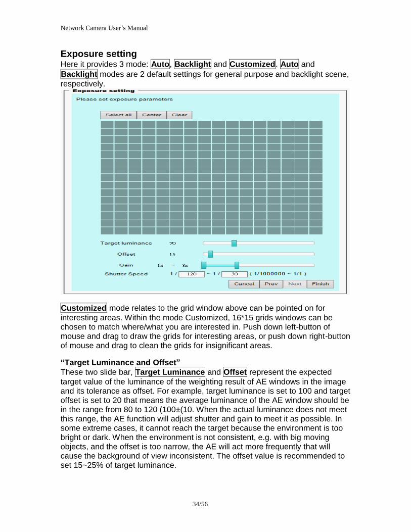
Network Camera Userrsquos Manual
3756
(2)ldquoSunrdquoldquoMonrdquoldquoTuerdquoldquoWedrdquoldquoThurdquoldquoFrirdquoldquoSatrdquo Select the days of the week to perform the application
(3) ldquoStart dayrdquo and ldquoStart timerdquo as the start timing the time ldquoEnd dayrdquo and ldquoEnd timerdquo as the end timing the time
(4) ldquoEnable cyclic recordingrdquo The cyclic recording function is enabled during the transaction stage when a storage space is full and the incoming streaming data is about to overwrite the previously saved videos
Record parameters (1)Source Select a stream for the recording source
(2)Recording interval Select the recording time interval
(3)Prefix file name You can setting the file name and enable or disable to add the date and time on file name
Response mode There are two choices of server types available NAS SD Card Select the item to display the detailed configuration options
(1)rdquoNASrdquo
--ldquoNAS server addressrdquo Enter IP address of the NAS server
--ldquoNAS shared directoryrdquo Enter the NAS shared directory path --ldquoWorkgrouprdquo Enter the NAS workgroup parameter --ldquoUser accountrdquo Enter the login name of the NAS account --ldquoUser passwordrdquo Enter the password of the NAS account Note Video record with the Application must be set to the same shared directory
path If you would like do detail recording settings or multi-channel recording please install bundled 64CH recording software in CD
Network Camera Userrsquos Manual
3856
Stream
Audio codec setting
(1)ldquoAudio codec typerdquo There are two choices of audio codec types
available rdquoAMRrdquo ldquoAACrdquo and rdquoG711rdquo
(2) ldquoBit raterdquo -- ldquoAMRrdquo The bit rates are selectable at the following rates
47505150590067007400795010200 and 12200
-- ldquoAACrdquo The bit rates are selectable at the following rates 8Kbps16Kbps 24Kbps and 32Kbps
-- ldquoG711rdquo pcmu and pcma
Video codec setting (1) ldquoSelect Streamrdquo The Network Camera supports ldquoStream 1rdquoand ldquoStream 2rdquo
(2) ldquoVideo codecrdquo The Network Camera supports three kind of video compression mode ldquoH264rdquo or ldquoMPEG4rdquo or ldquoMJPEGrdquo User can choose one of
Network Camera Userrsquos Manual
3956
these compression modes based on requirement or application
(3) ldquoVideo sizerdquo Click the down arrow to choose the quality of image (1920x1080 1280x1024 1280x800 640x480 320x240 176x144)
(4) ldquoConnection typerdquo User can select this button to choose the better video amp links quality (Internet mode or Intranet mode)
(5) ldquoFrame raterdquo This limits the maximal refresh frame rate per second Set the frame rate higher for a smoother video quality
(6) ldquoIntra frame periodrdquo Determine how often to plant an ldquoI framerdquo The shorter the duration the more likely you will get a better video quality but at the cost of higher network bandwidth consumption
(7) ldquoVideo Quality typerdquo Setting optimizes bandwidth utilization and video quality
-- ldquoConstant bit raterdquo User can adjust the video quality from 20 Kbps to 12 Mbps
-- ldquoFixed qualityrdquo user can select from lowest quality to get best quality according The ldquoQualityrdquo are selectable at the following rates From 1 to 20
Snapshot and time display setting Adjust the photo size specifications and choose whether to mark time on the video and photo
Network Camera Userrsquos Manual
4056
Application
Schedule mode
(1) ldquoEvery dayrdquo EnableDisable every day application
(2) ldquoWeek dayrdquo EnableDisable week day application
(3) ldquoSelected dayrdquo EnableDisable selected day application
Schedule information (1) Enter the ldquoStart timerdquo and ldquoStop timerdquo for day mode
Note that the time format is [hhmmss] and is expressed in 24-hour clock time By default the start and end time of day mode are set to 010000 and 235959
(2) ldquoSunrdquoldquoMonrdquoldquoTuerdquoldquoWedrdquoldquoThurdquoldquoFrirdquoldquoSatrdquo Select the days of the week to perform the application
(3) ldquoStart dayrdquo and ldquoStart timerdquo as the start timing the time ldquoEnd dayrdquo and ldquoEnd timerdquo as the end timing the time
Trigger mode
(1) ldquoVideo motion detectionrdquo EnableDisable video motion application (2) ldquoPeriodicallyrdquo This option allows the Network Camera to trigger
periodically for every other defined minute
Network Camera Userrsquos Manual
4156
(3) ldquoDigital inputrdquo This option allows the Network Camera to use an external digital input device or sensor as a trigger source Depending on your application there are many choices of digital input devices on the market which helps to detect changes in temperature vibration sound and light etc
parameters
(1) ldquoMotion parametersrdquo Higher sensitivity and small threshold will allow easier motion detection
(2) ldquoPeriod parametersrdquo This option allows the Network Camera to trigger periodically for every other defined seconds Up to 999 seconds are allowed
(3) ldquoDigital input parametersrdquo Select the digital input type and set trigger time
Media mode There are four choices of media types available ldquoSnapshotrdquo ldquoMessagerdquo ldquoRecord(Motion Detection only)rdquo and ldquoSystem logrdquo
Snapshot amp Record file setting You can setting the file name and enable or disable to add the date and time on file name Can setting the digital output duration seconds Response mode There are four choices of server types available Email FTP NAS and SD Card storage Select the item to display the detailed configuration options
(1)ldquoEmailrdquo -- ldquoEmail security moderdquo If your SMTP server requires a secure connection (SSL or TLS) check This server requires a secure connection (SSL or TLS) -- ldquoSender emailrdquo address Enter the email address of the sender -- ldquoRecipient emailrdquo address Enter the email address of the recipient
-- ldquoServer addressrdquo Enter the domain name or IP address of the email server
--ldquoUser namerdquo Enter the user name of the email account if necessary
--ldquoPasswordrdquo Enter the password of the email account if necessary
--ldquoServer portrdquo The default mail server port is set to 25 You can also manually set another port
(2)rdquoFTPrdquo -- ldquoServer addressrdquo Enter the domain name or IP address of the FTP server
-- ldquoServer portrdquo By default the FTP server port is set to 21
-- ldquoUser namerdquo Enter the login name of the FTP account
-- ldquoPasswordrdquo Enter the password of the FTP account
-- ldquoFTP folder namerdquo Enter the folder where the media file will be placed If the folder name does not exist the Network Camera will create one on the FTP server
(3)rdquoHTTP rdquo
-- ldquoURLrdquo Enter the URL of the HTTP server
-- ldquoUser accountrdquo Enter the user name if necessary -- ldquoUser passwordrdquo Enter the password if necessary
(4)rdquoNASrdquo --ldquoNAS server addressrdquo Enter IP address of the NAS server
--ldquoNAS shared directoryrdquo Enter the NAS shared directory path
Network Camera Userrsquos Manual
4256
--ldquoWorkgrouprdquo Enter the NAS workgroup parameter --ldquoUser accountrdquo Enter the login name of the NAS account --ldquoUser passwordrdquo Enter the password of the NAS account Note Video record with the Application must be set to the same shared directory
path If you would like do detail recording settings or multi-channel recording please install bundled 64CH recording software in CD
Network Camera Userrsquos Manual
4356
Storage
Manage the storage device
S torage Status Here show the storage device information
NAS server setting
1
2
3
Network Camera Userrsquos Manual
4456
(1) ldquoNAS Host namerdquo Choose and input the NAS Host name of this camera
(2) ldquoWorkgrouprdquo Input the name of Workgroup You can see the NAS Host name you input in the same workgroup with your PC Then you can connect to this device and download the files easily from SD card which is inserted to this camera
File operation Move the mouse over the file Press the mouse right button that Right-click menu is displayed You can delete files Move the mouse over the directory Press the mouse left button that the file structure expand Press the mouse right button that Right-click menu is displayed You can choose upload or delete files NOTEAllow the user to upload or delete files when the storage device is not write-
protected If the SD card canrsquot be detected please link to the following URL httpwwwsdcardorgconsumersformatter to download the ldquoSD Formatter Kitrdquo formatting your SD card
Network Camera Userrsquos Manual
4556
Syslog
The Network camera supports log the system messages on remote server The protocol is compliant to RFC 3164 If you have external Linux server with sys log service use ldquo-rrdquo option to turn on the facility for receiving log from remote machine Or you can use some software on Windows that is compliant to RFC 3164 An example is Kiwi Syslog Daemon Visit httpwwwkiwisyslogcomkiwi-syslog-daemon-overview Check ldquoSetuprdquo and ldquoEnablerdquo then input the ldquoIP addressrdquo and ldquoportrdquo number of the log server to enable the remote log facility In the ldquoCurrent logrdquo it displays the current system log file The content of the log provides useful information about configuration and connection after system boot- up
ldquofinishrdquo Click on this button to save modify settings
Network Camera Userrsquos Manual
4656
Status and Parameters
User can find a lot of information about the system such as ldquoUpnp port forwardingrdquo
ldquoTraversing NATrdquo ldquoPublic IPrdquo and so on User also can get the number of current viewer of the Network Camera here
Network Camera Userrsquos Manual
4756
Maintenance
1 ldquoReboot systemrdquo The ldquoRebootrdquo button will reboot the Network Camera Itrsquos useful while the Network Camera got problem 2 ldquoRestore systemrdquo Click on ldquoRestorerdquo button on the configuration page to restore the factory default settings Restore all settings to factory default except settings in ldquoNetwork type rdquo and ldquoRoot Passwordrdquo The system will restart and require the installer program to set up the network again
3 ldquoCalibraterdquo Recalibrate the auto focus position to the default range to recover the tolerance caused by some external forces 4 ldquoExportImport filerdquo -- Export setting backup file Click to export all parameters for the device and user-defined scripts
-- Upload setting backup file Click Browsehellip to upload a setting backup file Please note that the model and firmware version of the device should be the same as the setting backup file If you have set up a fixed IP or other special settings for your device it is not suggested to upload a settings backup file
4 ldquoUpgrade firmwarerdquo Select the firmware file and click upgrade button Please be aware that you should not turn off the power during updating the firmware and wait for finish message
Network Camera Userrsquos Manual
4856
Warning The upgrade firmware procedure cannot be interrupted If the power
andor network connection are broken during the procedure it might possibly cause serious damage to the Network Camera
Note When upgrade firmware please wait for 120~210 seconds and then you can connect to Network Camera again The system will restart and require the installer program to set up the network again
Network Camera Userrsquos Manual
4956
Appendix
A Troubleshooting amp Frequently Asked Questions Q1 Status led does not light up
A1 First make sure that「ConfigurationgtSystemgtTurn off the LED indicator」is disabled
If it is check the item and the led should light up Second if red led does not light up please check that the power adapter in the package is plugged correctly And last if green led does not light up please check that category 5 UTP cable is plugged correctly If the problem is still not solved please contact your dealer for further help
Q2 What kind of Ethernet cable is used by network camera
A2 The network Camera uses Category 5 UTP cable allowing 10 andor 100 Base-T networking
Q3 The Network Camera will be installed and work if a firewall exists on
the network
A3 There are two way to set up the IP camera at Internet (1) By UPnP Port Forwarding 1 Select an IP router It must support UPnP port forwarding and enable this function
first
2 Connect camera RJ45 cable to IP router and the router is also connected to Internet
3 Plug power cord to camera
4 Go to camera Network page Enable UPnP port forwarding
5 Check camera status we can see the ports had been successfully opened
Network Camera Userrsquos Manual
5056
6Type IP address8080 at browser Then you can see camera through Internet
7You can also type the ddns name at below label of camera on browser URL field For example you may type ah00001ip-discoverycom8080 (2) By Setting Port Forwarding Manually 1 Select a router Set the port forwarding as following
Network Camera Userrsquos Manual
5156
PS Port 80 is HTTP Port port 53 is stream port port 554 is RTSP port and port 443 is HTTPS port 2Go to camera Network page Disable UPnP port forwarding function
Network Camera Userrsquos Manual
5256
3 Type IP address at browser Then you can see camera through Internet
4 You can also type the ddns name at below label of camera on browser URL field For example you may type ah00001ip-discoverycom
Note The firewall software at PC may block the transfer of network camera Please remove or stop the kind software
Q4 How can I find the network camera in the local area network
A4 By using the IP Finder2 program or using UPnP to find it
Q5 IP Finder2 program cannot find Network Camera in the local area
network at first time
A5 Make sure the subnet of network camera is same as your PC If the local area network supports DHCP the camera is ldquoGet IP address automaticallyrdquo in the ldquoNetworkrdquo page default If the local area network does not support DHCP change your PC IP address to ldquo1921680xxxrdquo
Network Camera Userrsquos Manual
5356
Q6 How can I restore the network camera to default value
A6 Use a gem clip to press on the inside button Network camera begins to restore default value You can also press the button ldquoFactoryrdquo in ldquoMaintenancerdquo page to restore the default value
Q7 I cannot play the recorded video file
A7 Install the audio codec in the CD and use the Windows Media Player 10 or later to play the ASF or AVI file recorded by the network camera
Q8 Infrared led does not light up
A8 Check「ConfigurationgtAudio and VideogtInfrared LED Control」 is ldquoAutordquo or
ldquoManual》Turn onrdquo
Q9 The network camera cannot focus accurately
A9 (1) The lens is dirty or dust is attached Clean the lens with lens cleaner And then adjust the camera focus manually (2) The image may be out of focus If the object is too near move the object away from Network Camera
Q10 The cover of network camera is warm Is it normal
A10 Network camera is a precision device The internal material has the operational temperature and it is normal when user touch the cover feels warm It is recommended to put the network camera at aired place and not put at any other device
Q11 The process of upgrade firmware abort
A11 Contact your dealer for further help
Q12 Cannot access the login page and other web pages of Network
Network Camera Userrsquos Manual
5456
Camera from Internet Explorer
A12 bull May be due to the network cable Try correcting your network cable and configuration Test the network interface by connecting a local computer to the Network Camera via a crossover cable bull Make sure the Internet connection and setting is ok bull Make sure enter the IP address of Internet Explorer is correct If Network Camera has a dynamic address it may have changed since you last checked it bull Network congestion may prevent the web page appearing quickly Wait for a while The IP address and Subnet Mask of the PC and Network Camera must be in the same class of the private IP address on the LAN bull Make sure the http port used by the Network Camera default=80 is forward to the Network Camerarsquos private IP address bull The port number assigned in your Network Camera might not be available via Internet Check your ISP for available port bull The proxy server may prevent you from connecting directly to Network Camera set up not to use the proxy server bull Confirm that Default Gateway address is correct bull The router needs Port Forwarding feature Refer to your routers manual for details bull Packet Filtering of the router may prohibit access from an external network Refer to your routers manual for details bull Access Network Camera from the Internet with the global IP address of the router and port number of Network Camera bull Some routers reject the global IP address to access Network Camera on the same LAN Access with the private IP address and correct port number of Network Camera bull When you use DDNS you need to set Default Gateway and DNS server address bull If itrsquos not working after above procedure reset Network Camera to default setting and installed it again bull Maybe the IP Address of the Network Camera is already being used by another device or computer bull If the problem is not solved the Network Camera might be faulty Contact your dealer for further help
Network Camera Userrsquos Manual
5556
B Technical specifications
- System RAM 4G bit DDRⅢ
ROM 16MB Flash ROM
- Camera specification 127 inch color CMOS sensor Resolution 1920x1080 10LuxF20 AGC AWB AEC
- Infrared Led High power IR Leds 25~30 M visible AutoManual mode
- Lens 3X optical zoom lens auto iris auto focus f = 28~ 12mm F18 Fov(D) 136deg ~ 39deg
- Protocol TCPIP HTTPUDP SMTP FTP DDNS UPnP Telnet NTP PPPoE RTSP RTPRTCPDHCP and DNS
- Video Resolution Up to 30 frames at 176x144 Up to 30 frames at 320x240 Up to 30 frames at 640x480 Up to 30 frames at 1280x800 Up to 30 frames at 1280x1024 Up to 30 frames at 1920x1080
- Algorithm supported H264MPEG4MJPEG dual codec for streaming video JPEG for still image
- Audio AMRAACG711 External MIC input 2-way audio
- Physical 10 baseT100 baseT and 1000 baseT Fast
Ethernet auto negotiation
- Power Input 100-240VAC 5060Hz 07A Output 12VDC 15A Consumption Max 12 W Support 8023af compliant Power over Ethernet
- EMI amp Safety CE FCC
- Dimension Length 165mm Diameter 75mm
- Operating Environment Temperature -20 ~ 50
Humidity 85 RH
- Weight NET 600g With bracket 800g
Network Camera Userrsquos Manual
5656
Notification of Compliance Appendix C
Europe - EU Declaration of Conformity
For complete DoC please visit httpgloballevel1comdownloadsphpaction=init
GPL License Agreement GPL may be included in this product to view the GPL license agreement goes to httpdownloadlevel1comlevel1gplGPLpdf For GNU General Public License (GPL) related information please visit httpgloballevel1comdownloadsphpaction=init
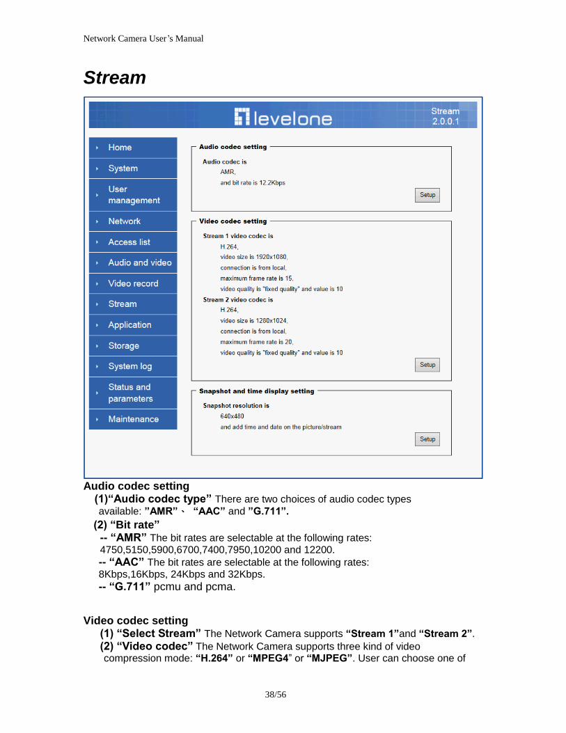
Network Camera Userrsquos Manual
3856
Stream
Audio codec setting
(1)ldquoAudio codec typerdquo There are two choices of audio codec types
available rdquoAMRrdquo ldquoAACrdquo and rdquoG711rdquo
(2) ldquoBit raterdquo -- ldquoAMRrdquo The bit rates are selectable at the following rates
47505150590067007400795010200 and 12200
-- ldquoAACrdquo The bit rates are selectable at the following rates 8Kbps16Kbps 24Kbps and 32Kbps
-- ldquoG711rdquo pcmu and pcma
Video codec setting (1) ldquoSelect Streamrdquo The Network Camera supports ldquoStream 1rdquoand ldquoStream 2rdquo
(2) ldquoVideo codecrdquo The Network Camera supports three kind of video compression mode ldquoH264rdquo or ldquoMPEG4rdquo or ldquoMJPEGrdquo User can choose one of
Network Camera Userrsquos Manual
3956
these compression modes based on requirement or application
(3) ldquoVideo sizerdquo Click the down arrow to choose the quality of image (1920x1080 1280x1024 1280x800 640x480 320x240 176x144)
(4) ldquoConnection typerdquo User can select this button to choose the better video amp links quality (Internet mode or Intranet mode)
(5) ldquoFrame raterdquo This limits the maximal refresh frame rate per second Set the frame rate higher for a smoother video quality
(6) ldquoIntra frame periodrdquo Determine how often to plant an ldquoI framerdquo The shorter the duration the more likely you will get a better video quality but at the cost of higher network bandwidth consumption
(7) ldquoVideo Quality typerdquo Setting optimizes bandwidth utilization and video quality
-- ldquoConstant bit raterdquo User can adjust the video quality from 20 Kbps to 12 Mbps
-- ldquoFixed qualityrdquo user can select from lowest quality to get best quality according The ldquoQualityrdquo are selectable at the following rates From 1 to 20
Snapshot and time display setting Adjust the photo size specifications and choose whether to mark time on the video and photo
Network Camera Userrsquos Manual
4056
Application
Schedule mode
(1) ldquoEvery dayrdquo EnableDisable every day application
(2) ldquoWeek dayrdquo EnableDisable week day application
(3) ldquoSelected dayrdquo EnableDisable selected day application
Schedule information (1) Enter the ldquoStart timerdquo and ldquoStop timerdquo for day mode
Note that the time format is [hhmmss] and is expressed in 24-hour clock time By default the start and end time of day mode are set to 010000 and 235959
(2) ldquoSunrdquoldquoMonrdquoldquoTuerdquoldquoWedrdquoldquoThurdquoldquoFrirdquoldquoSatrdquo Select the days of the week to perform the application
(3) ldquoStart dayrdquo and ldquoStart timerdquo as the start timing the time ldquoEnd dayrdquo and ldquoEnd timerdquo as the end timing the time
Trigger mode
(1) ldquoVideo motion detectionrdquo EnableDisable video motion application (2) ldquoPeriodicallyrdquo This option allows the Network Camera to trigger
periodically for every other defined minute
Network Camera Userrsquos Manual
4156
(3) ldquoDigital inputrdquo This option allows the Network Camera to use an external digital input device or sensor as a trigger source Depending on your application there are many choices of digital input devices on the market which helps to detect changes in temperature vibration sound and light etc
parameters
(1) ldquoMotion parametersrdquo Higher sensitivity and small threshold will allow easier motion detection
(2) ldquoPeriod parametersrdquo This option allows the Network Camera to trigger periodically for every other defined seconds Up to 999 seconds are allowed
(3) ldquoDigital input parametersrdquo Select the digital input type and set trigger time
Media mode There are four choices of media types available ldquoSnapshotrdquo ldquoMessagerdquo ldquoRecord(Motion Detection only)rdquo and ldquoSystem logrdquo
Snapshot amp Record file setting You can setting the file name and enable or disable to add the date and time on file name Can setting the digital output duration seconds Response mode There are four choices of server types available Email FTP NAS and SD Card storage Select the item to display the detailed configuration options
(1)ldquoEmailrdquo -- ldquoEmail security moderdquo If your SMTP server requires a secure connection (SSL or TLS) check This server requires a secure connection (SSL or TLS) -- ldquoSender emailrdquo address Enter the email address of the sender -- ldquoRecipient emailrdquo address Enter the email address of the recipient
-- ldquoServer addressrdquo Enter the domain name or IP address of the email server
--ldquoUser namerdquo Enter the user name of the email account if necessary
--ldquoPasswordrdquo Enter the password of the email account if necessary
--ldquoServer portrdquo The default mail server port is set to 25 You can also manually set another port
(2)rdquoFTPrdquo -- ldquoServer addressrdquo Enter the domain name or IP address of the FTP server
-- ldquoServer portrdquo By default the FTP server port is set to 21
-- ldquoUser namerdquo Enter the login name of the FTP account
-- ldquoPasswordrdquo Enter the password of the FTP account
-- ldquoFTP folder namerdquo Enter the folder where the media file will be placed If the folder name does not exist the Network Camera will create one on the FTP server
(3)rdquoHTTP rdquo
-- ldquoURLrdquo Enter the URL of the HTTP server
-- ldquoUser accountrdquo Enter the user name if necessary -- ldquoUser passwordrdquo Enter the password if necessary
(4)rdquoNASrdquo --ldquoNAS server addressrdquo Enter IP address of the NAS server
--ldquoNAS shared directoryrdquo Enter the NAS shared directory path
Network Camera Userrsquos Manual
4256
--ldquoWorkgrouprdquo Enter the NAS workgroup parameter --ldquoUser accountrdquo Enter the login name of the NAS account --ldquoUser passwordrdquo Enter the password of the NAS account Note Video record with the Application must be set to the same shared directory
path If you would like do detail recording settings or multi-channel recording please install bundled 64CH recording software in CD
Network Camera Userrsquos Manual
4356
Storage
Manage the storage device
S torage Status Here show the storage device information
NAS server setting
1
2
3
Network Camera Userrsquos Manual
4456
(1) ldquoNAS Host namerdquo Choose and input the NAS Host name of this camera
(2) ldquoWorkgrouprdquo Input the name of Workgroup You can see the NAS Host name you input in the same workgroup with your PC Then you can connect to this device and download the files easily from SD card which is inserted to this camera
File operation Move the mouse over the file Press the mouse right button that Right-click menu is displayed You can delete files Move the mouse over the directory Press the mouse left button that the file structure expand Press the mouse right button that Right-click menu is displayed You can choose upload or delete files NOTEAllow the user to upload or delete files when the storage device is not write-
protected If the SD card canrsquot be detected please link to the following URL httpwwwsdcardorgconsumersformatter to download the ldquoSD Formatter Kitrdquo formatting your SD card
Network Camera Userrsquos Manual
4556
Syslog
The Network camera supports log the system messages on remote server The protocol is compliant to RFC 3164 If you have external Linux server with sys log service use ldquo-rrdquo option to turn on the facility for receiving log from remote machine Or you can use some software on Windows that is compliant to RFC 3164 An example is Kiwi Syslog Daemon Visit httpwwwkiwisyslogcomkiwi-syslog-daemon-overview Check ldquoSetuprdquo and ldquoEnablerdquo then input the ldquoIP addressrdquo and ldquoportrdquo number of the log server to enable the remote log facility In the ldquoCurrent logrdquo it displays the current system log file The content of the log provides useful information about configuration and connection after system boot- up
ldquofinishrdquo Click on this button to save modify settings
Network Camera Userrsquos Manual
4656
Status and Parameters
User can find a lot of information about the system such as ldquoUpnp port forwardingrdquo
ldquoTraversing NATrdquo ldquoPublic IPrdquo and so on User also can get the number of current viewer of the Network Camera here
Network Camera Userrsquos Manual
4756
Maintenance
1 ldquoReboot systemrdquo The ldquoRebootrdquo button will reboot the Network Camera Itrsquos useful while the Network Camera got problem 2 ldquoRestore systemrdquo Click on ldquoRestorerdquo button on the configuration page to restore the factory default settings Restore all settings to factory default except settings in ldquoNetwork type rdquo and ldquoRoot Passwordrdquo The system will restart and require the installer program to set up the network again
3 ldquoCalibraterdquo Recalibrate the auto focus position to the default range to recover the tolerance caused by some external forces 4 ldquoExportImport filerdquo -- Export setting backup file Click to export all parameters for the device and user-defined scripts
-- Upload setting backup file Click Browsehellip to upload a setting backup file Please note that the model and firmware version of the device should be the same as the setting backup file If you have set up a fixed IP or other special settings for your device it is not suggested to upload a settings backup file
4 ldquoUpgrade firmwarerdquo Select the firmware file and click upgrade button Please be aware that you should not turn off the power during updating the firmware and wait for finish message
Network Camera Userrsquos Manual
4856
Warning The upgrade firmware procedure cannot be interrupted If the power
andor network connection are broken during the procedure it might possibly cause serious damage to the Network Camera
Note When upgrade firmware please wait for 120~210 seconds and then you can connect to Network Camera again The system will restart and require the installer program to set up the network again
Network Camera Userrsquos Manual
4956
Appendix
A Troubleshooting amp Frequently Asked Questions Q1 Status led does not light up
A1 First make sure that「ConfigurationgtSystemgtTurn off the LED indicator」is disabled
If it is check the item and the led should light up Second if red led does not light up please check that the power adapter in the package is plugged correctly And last if green led does not light up please check that category 5 UTP cable is plugged correctly If the problem is still not solved please contact your dealer for further help
Q2 What kind of Ethernet cable is used by network camera
A2 The network Camera uses Category 5 UTP cable allowing 10 andor 100 Base-T networking
Q3 The Network Camera will be installed and work if a firewall exists on
the network
A3 There are two way to set up the IP camera at Internet (1) By UPnP Port Forwarding 1 Select an IP router It must support UPnP port forwarding and enable this function
first
2 Connect camera RJ45 cable to IP router and the router is also connected to Internet
3 Plug power cord to camera
4 Go to camera Network page Enable UPnP port forwarding
5 Check camera status we can see the ports had been successfully opened
Network Camera Userrsquos Manual
5056
6Type IP address8080 at browser Then you can see camera through Internet
7You can also type the ddns name at below label of camera on browser URL field For example you may type ah00001ip-discoverycom8080 (2) By Setting Port Forwarding Manually 1 Select a router Set the port forwarding as following
Network Camera Userrsquos Manual
5156
PS Port 80 is HTTP Port port 53 is stream port port 554 is RTSP port and port 443 is HTTPS port 2Go to camera Network page Disable UPnP port forwarding function
Network Camera Userrsquos Manual
5256
3 Type IP address at browser Then you can see camera through Internet
4 You can also type the ddns name at below label of camera on browser URL field For example you may type ah00001ip-discoverycom
Note The firewall software at PC may block the transfer of network camera Please remove or stop the kind software
Q4 How can I find the network camera in the local area network
A4 By using the IP Finder2 program or using UPnP to find it
Q5 IP Finder2 program cannot find Network Camera in the local area
network at first time
A5 Make sure the subnet of network camera is same as your PC If the local area network supports DHCP the camera is ldquoGet IP address automaticallyrdquo in the ldquoNetworkrdquo page default If the local area network does not support DHCP change your PC IP address to ldquo1921680xxxrdquo
Network Camera Userrsquos Manual
5356
Q6 How can I restore the network camera to default value
A6 Use a gem clip to press on the inside button Network camera begins to restore default value You can also press the button ldquoFactoryrdquo in ldquoMaintenancerdquo page to restore the default value
Q7 I cannot play the recorded video file
A7 Install the audio codec in the CD and use the Windows Media Player 10 or later to play the ASF or AVI file recorded by the network camera
Q8 Infrared led does not light up
A8 Check「ConfigurationgtAudio and VideogtInfrared LED Control」 is ldquoAutordquo or
ldquoManual》Turn onrdquo
Q9 The network camera cannot focus accurately
A9 (1) The lens is dirty or dust is attached Clean the lens with lens cleaner And then adjust the camera focus manually (2) The image may be out of focus If the object is too near move the object away from Network Camera
Q10 The cover of network camera is warm Is it normal
A10 Network camera is a precision device The internal material has the operational temperature and it is normal when user touch the cover feels warm It is recommended to put the network camera at aired place and not put at any other device
Q11 The process of upgrade firmware abort
A11 Contact your dealer for further help
Q12 Cannot access the login page and other web pages of Network
Network Camera Userrsquos Manual
5456
Camera from Internet Explorer
A12 bull May be due to the network cable Try correcting your network cable and configuration Test the network interface by connecting a local computer to the Network Camera via a crossover cable bull Make sure the Internet connection and setting is ok bull Make sure enter the IP address of Internet Explorer is correct If Network Camera has a dynamic address it may have changed since you last checked it bull Network congestion may prevent the web page appearing quickly Wait for a while The IP address and Subnet Mask of the PC and Network Camera must be in the same class of the private IP address on the LAN bull Make sure the http port used by the Network Camera default=80 is forward to the Network Camerarsquos private IP address bull The port number assigned in your Network Camera might not be available via Internet Check your ISP for available port bull The proxy server may prevent you from connecting directly to Network Camera set up not to use the proxy server bull Confirm that Default Gateway address is correct bull The router needs Port Forwarding feature Refer to your routers manual for details bull Packet Filtering of the router may prohibit access from an external network Refer to your routers manual for details bull Access Network Camera from the Internet with the global IP address of the router and port number of Network Camera bull Some routers reject the global IP address to access Network Camera on the same LAN Access with the private IP address and correct port number of Network Camera bull When you use DDNS you need to set Default Gateway and DNS server address bull If itrsquos not working after above procedure reset Network Camera to default setting and installed it again bull Maybe the IP Address of the Network Camera is already being used by another device or computer bull If the problem is not solved the Network Camera might be faulty Contact your dealer for further help
Network Camera Userrsquos Manual
5556
B Technical specifications
- System RAM 4G bit DDRⅢ
ROM 16MB Flash ROM
- Camera specification 127 inch color CMOS sensor Resolution 1920x1080 10LuxF20 AGC AWB AEC
- Infrared Led High power IR Leds 25~30 M visible AutoManual mode
- Lens 3X optical zoom lens auto iris auto focus f = 28~ 12mm F18 Fov(D) 136deg ~ 39deg
- Protocol TCPIP HTTPUDP SMTP FTP DDNS UPnP Telnet NTP PPPoE RTSP RTPRTCPDHCP and DNS
- Video Resolution Up to 30 frames at 176x144 Up to 30 frames at 320x240 Up to 30 frames at 640x480 Up to 30 frames at 1280x800 Up to 30 frames at 1280x1024 Up to 30 frames at 1920x1080
- Algorithm supported H264MPEG4MJPEG dual codec for streaming video JPEG for still image
- Audio AMRAACG711 External MIC input 2-way audio
- Physical 10 baseT100 baseT and 1000 baseT Fast
Ethernet auto negotiation
- Power Input 100-240VAC 5060Hz 07A Output 12VDC 15A Consumption Max 12 W Support 8023af compliant Power over Ethernet
- EMI amp Safety CE FCC
- Dimension Length 165mm Diameter 75mm
- Operating Environment Temperature -20 ~ 50
Humidity 85 RH
- Weight NET 600g With bracket 800g
Network Camera Userrsquos Manual
5656
Notification of Compliance Appendix C
Europe - EU Declaration of Conformity
For complete DoC please visit httpgloballevel1comdownloadsphpaction=init
GPL License Agreement GPL may be included in this product to view the GPL license agreement goes to httpdownloadlevel1comlevel1gplGPLpdf For GNU General Public License (GPL) related information please visit httpgloballevel1comdownloadsphpaction=init
Network Camera Userrsquos Manual
3956
these compression modes based on requirement or application
(3) ldquoVideo sizerdquo Click the down arrow to choose the quality of image (1920x1080 1280x1024 1280x800 640x480 320x240 176x144)
(4) ldquoConnection typerdquo User can select this button to choose the better video amp links quality (Internet mode or Intranet mode)
(5) ldquoFrame raterdquo This limits the maximal refresh frame rate per second Set the frame rate higher for a smoother video quality
(6) ldquoIntra frame periodrdquo Determine how often to plant an ldquoI framerdquo The shorter the duration the more likely you will get a better video quality but at the cost of higher network bandwidth consumption
(7) ldquoVideo Quality typerdquo Setting optimizes bandwidth utilization and video quality
-- ldquoConstant bit raterdquo User can adjust the video quality from 20 Kbps to 12 Mbps
-- ldquoFixed qualityrdquo user can select from lowest quality to get best quality according The ldquoQualityrdquo are selectable at the following rates From 1 to 20
Snapshot and time display setting Adjust the photo size specifications and choose whether to mark time on the video and photo
Network Camera Userrsquos Manual
4056
Application
Schedule mode
(1) ldquoEvery dayrdquo EnableDisable every day application
(2) ldquoWeek dayrdquo EnableDisable week day application
(3) ldquoSelected dayrdquo EnableDisable selected day application
Schedule information (1) Enter the ldquoStart timerdquo and ldquoStop timerdquo for day mode
Note that the time format is [hhmmss] and is expressed in 24-hour clock time By default the start and end time of day mode are set to 010000 and 235959
(2) ldquoSunrdquoldquoMonrdquoldquoTuerdquoldquoWedrdquoldquoThurdquoldquoFrirdquoldquoSatrdquo Select the days of the week to perform the application
(3) ldquoStart dayrdquo and ldquoStart timerdquo as the start timing the time ldquoEnd dayrdquo and ldquoEnd timerdquo as the end timing the time
Trigger mode
(1) ldquoVideo motion detectionrdquo EnableDisable video motion application (2) ldquoPeriodicallyrdquo This option allows the Network Camera to trigger
periodically for every other defined minute
Network Camera Userrsquos Manual
4156
(3) ldquoDigital inputrdquo This option allows the Network Camera to use an external digital input device or sensor as a trigger source Depending on your application there are many choices of digital input devices on the market which helps to detect changes in temperature vibration sound and light etc
parameters
(1) ldquoMotion parametersrdquo Higher sensitivity and small threshold will allow easier motion detection
(2) ldquoPeriod parametersrdquo This option allows the Network Camera to trigger periodically for every other defined seconds Up to 999 seconds are allowed
(3) ldquoDigital input parametersrdquo Select the digital input type and set trigger time
Media mode There are four choices of media types available ldquoSnapshotrdquo ldquoMessagerdquo ldquoRecord(Motion Detection only)rdquo and ldquoSystem logrdquo
Snapshot amp Record file setting You can setting the file name and enable or disable to add the date and time on file name Can setting the digital output duration seconds Response mode There are four choices of server types available Email FTP NAS and SD Card storage Select the item to display the detailed configuration options
(1)ldquoEmailrdquo -- ldquoEmail security moderdquo If your SMTP server requires a secure connection (SSL or TLS) check This server requires a secure connection (SSL or TLS) -- ldquoSender emailrdquo address Enter the email address of the sender -- ldquoRecipient emailrdquo address Enter the email address of the recipient
-- ldquoServer addressrdquo Enter the domain name or IP address of the email server
--ldquoUser namerdquo Enter the user name of the email account if necessary
--ldquoPasswordrdquo Enter the password of the email account if necessary
--ldquoServer portrdquo The default mail server port is set to 25 You can also manually set another port
(2)rdquoFTPrdquo -- ldquoServer addressrdquo Enter the domain name or IP address of the FTP server
-- ldquoServer portrdquo By default the FTP server port is set to 21
-- ldquoUser namerdquo Enter the login name of the FTP account
-- ldquoPasswordrdquo Enter the password of the FTP account
-- ldquoFTP folder namerdquo Enter the folder where the media file will be placed If the folder name does not exist the Network Camera will create one on the FTP server
(3)rdquoHTTP rdquo
-- ldquoURLrdquo Enter the URL of the HTTP server
-- ldquoUser accountrdquo Enter the user name if necessary -- ldquoUser passwordrdquo Enter the password if necessary
(4)rdquoNASrdquo --ldquoNAS server addressrdquo Enter IP address of the NAS server
--ldquoNAS shared directoryrdquo Enter the NAS shared directory path
Network Camera Userrsquos Manual
4256
--ldquoWorkgrouprdquo Enter the NAS workgroup parameter --ldquoUser accountrdquo Enter the login name of the NAS account --ldquoUser passwordrdquo Enter the password of the NAS account Note Video record with the Application must be set to the same shared directory
path If you would like do detail recording settings or multi-channel recording please install bundled 64CH recording software in CD
Network Camera Userrsquos Manual
4356
Storage
Manage the storage device
S torage Status Here show the storage device information
NAS server setting
1
2
3
Network Camera Userrsquos Manual
4456
(1) ldquoNAS Host namerdquo Choose and input the NAS Host name of this camera
(2) ldquoWorkgrouprdquo Input the name of Workgroup You can see the NAS Host name you input in the same workgroup with your PC Then you can connect to this device and download the files easily from SD card which is inserted to this camera
File operation Move the mouse over the file Press the mouse right button that Right-click menu is displayed You can delete files Move the mouse over the directory Press the mouse left button that the file structure expand Press the mouse right button that Right-click menu is displayed You can choose upload or delete files NOTEAllow the user to upload or delete files when the storage device is not write-
protected If the SD card canrsquot be detected please link to the following URL httpwwwsdcardorgconsumersformatter to download the ldquoSD Formatter Kitrdquo formatting your SD card
Network Camera Userrsquos Manual
4556
Syslog
The Network camera supports log the system messages on remote server The protocol is compliant to RFC 3164 If you have external Linux server with sys log service use ldquo-rrdquo option to turn on the facility for receiving log from remote machine Or you can use some software on Windows that is compliant to RFC 3164 An example is Kiwi Syslog Daemon Visit httpwwwkiwisyslogcomkiwi-syslog-daemon-overview Check ldquoSetuprdquo and ldquoEnablerdquo then input the ldquoIP addressrdquo and ldquoportrdquo number of the log server to enable the remote log facility In the ldquoCurrent logrdquo it displays the current system log file The content of the log provides useful information about configuration and connection after system boot- up
ldquofinishrdquo Click on this button to save modify settings
Network Camera Userrsquos Manual
4656
Status and Parameters
User can find a lot of information about the system such as ldquoUpnp port forwardingrdquo
ldquoTraversing NATrdquo ldquoPublic IPrdquo and so on User also can get the number of current viewer of the Network Camera here
Network Camera Userrsquos Manual
4756
Maintenance
1 ldquoReboot systemrdquo The ldquoRebootrdquo button will reboot the Network Camera Itrsquos useful while the Network Camera got problem 2 ldquoRestore systemrdquo Click on ldquoRestorerdquo button on the configuration page to restore the factory default settings Restore all settings to factory default except settings in ldquoNetwork type rdquo and ldquoRoot Passwordrdquo The system will restart and require the installer program to set up the network again
3 ldquoCalibraterdquo Recalibrate the auto focus position to the default range to recover the tolerance caused by some external forces 4 ldquoExportImport filerdquo -- Export setting backup file Click to export all parameters for the device and user-defined scripts
-- Upload setting backup file Click Browsehellip to upload a setting backup file Please note that the model and firmware version of the device should be the same as the setting backup file If you have set up a fixed IP or other special settings for your device it is not suggested to upload a settings backup file
4 ldquoUpgrade firmwarerdquo Select the firmware file and click upgrade button Please be aware that you should not turn off the power during updating the firmware and wait for finish message
Network Camera Userrsquos Manual
4856
Warning The upgrade firmware procedure cannot be interrupted If the power
andor network connection are broken during the procedure it might possibly cause serious damage to the Network Camera
Note When upgrade firmware please wait for 120~210 seconds and then you can connect to Network Camera again The system will restart and require the installer program to set up the network again
Network Camera Userrsquos Manual
4956
Appendix
A Troubleshooting amp Frequently Asked Questions Q1 Status led does not light up
A1 First make sure that「ConfigurationgtSystemgtTurn off the LED indicator」is disabled
If it is check the item and the led should light up Second if red led does not light up please check that the power adapter in the package is plugged correctly And last if green led does not light up please check that category 5 UTP cable is plugged correctly If the problem is still not solved please contact your dealer for further help
Q2 What kind of Ethernet cable is used by network camera
A2 The network Camera uses Category 5 UTP cable allowing 10 andor 100 Base-T networking
Q3 The Network Camera will be installed and work if a firewall exists on
the network
A3 There are two way to set up the IP camera at Internet (1) By UPnP Port Forwarding 1 Select an IP router It must support UPnP port forwarding and enable this function
first
2 Connect camera RJ45 cable to IP router and the router is also connected to Internet
3 Plug power cord to camera
4 Go to camera Network page Enable UPnP port forwarding
5 Check camera status we can see the ports had been successfully opened
Network Camera Userrsquos Manual
5056
6Type IP address8080 at browser Then you can see camera through Internet
7You can also type the ddns name at below label of camera on browser URL field For example you may type ah00001ip-discoverycom8080 (2) By Setting Port Forwarding Manually 1 Select a router Set the port forwarding as following
Network Camera Userrsquos Manual
5156
PS Port 80 is HTTP Port port 53 is stream port port 554 is RTSP port and port 443 is HTTPS port 2Go to camera Network page Disable UPnP port forwarding function
Network Camera Userrsquos Manual
5256
3 Type IP address at browser Then you can see camera through Internet
4 You can also type the ddns name at below label of camera on browser URL field For example you may type ah00001ip-discoverycom
Note The firewall software at PC may block the transfer of network camera Please remove or stop the kind software
Q4 How can I find the network camera in the local area network
A4 By using the IP Finder2 program or using UPnP to find it
Q5 IP Finder2 program cannot find Network Camera in the local area
network at first time
A5 Make sure the subnet of network camera is same as your PC If the local area network supports DHCP the camera is ldquoGet IP address automaticallyrdquo in the ldquoNetworkrdquo page default If the local area network does not support DHCP change your PC IP address to ldquo1921680xxxrdquo
Network Camera Userrsquos Manual
5356
Q6 How can I restore the network camera to default value
A6 Use a gem clip to press on the inside button Network camera begins to restore default value You can also press the button ldquoFactoryrdquo in ldquoMaintenancerdquo page to restore the default value
Q7 I cannot play the recorded video file
A7 Install the audio codec in the CD and use the Windows Media Player 10 or later to play the ASF or AVI file recorded by the network camera
Q8 Infrared led does not light up
A8 Check「ConfigurationgtAudio and VideogtInfrared LED Control」 is ldquoAutordquo or
ldquoManual》Turn onrdquo
Q9 The network camera cannot focus accurately
A9 (1) The lens is dirty or dust is attached Clean the lens with lens cleaner And then adjust the camera focus manually (2) The image may be out of focus If the object is too near move the object away from Network Camera
Q10 The cover of network camera is warm Is it normal
A10 Network camera is a precision device The internal material has the operational temperature and it is normal when user touch the cover feels warm It is recommended to put the network camera at aired place and not put at any other device
Q11 The process of upgrade firmware abort
A11 Contact your dealer for further help
Q12 Cannot access the login page and other web pages of Network
Network Camera Userrsquos Manual
5456
Camera from Internet Explorer
A12 bull May be due to the network cable Try correcting your network cable and configuration Test the network interface by connecting a local computer to the Network Camera via a crossover cable bull Make sure the Internet connection and setting is ok bull Make sure enter the IP address of Internet Explorer is correct If Network Camera has a dynamic address it may have changed since you last checked it bull Network congestion may prevent the web page appearing quickly Wait for a while The IP address and Subnet Mask of the PC and Network Camera must be in the same class of the private IP address on the LAN bull Make sure the http port used by the Network Camera default=80 is forward to the Network Camerarsquos private IP address bull The port number assigned in your Network Camera might not be available via Internet Check your ISP for available port bull The proxy server may prevent you from connecting directly to Network Camera set up not to use the proxy server bull Confirm that Default Gateway address is correct bull The router needs Port Forwarding feature Refer to your routers manual for details bull Packet Filtering of the router may prohibit access from an external network Refer to your routers manual for details bull Access Network Camera from the Internet with the global IP address of the router and port number of Network Camera bull Some routers reject the global IP address to access Network Camera on the same LAN Access with the private IP address and correct port number of Network Camera bull When you use DDNS you need to set Default Gateway and DNS server address bull If itrsquos not working after above procedure reset Network Camera to default setting and installed it again bull Maybe the IP Address of the Network Camera is already being used by another device or computer bull If the problem is not solved the Network Camera might be faulty Contact your dealer for further help
Network Camera Userrsquos Manual
5556
B Technical specifications
- System RAM 4G bit DDRⅢ
ROM 16MB Flash ROM
- Camera specification 127 inch color CMOS sensor Resolution 1920x1080 10LuxF20 AGC AWB AEC
- Infrared Led High power IR Leds 25~30 M visible AutoManual mode
- Lens 3X optical zoom lens auto iris auto focus f = 28~ 12mm F18 Fov(D) 136deg ~ 39deg
- Protocol TCPIP HTTPUDP SMTP FTP DDNS UPnP Telnet NTP PPPoE RTSP RTPRTCPDHCP and DNS
- Video Resolution Up to 30 frames at 176x144 Up to 30 frames at 320x240 Up to 30 frames at 640x480 Up to 30 frames at 1280x800 Up to 30 frames at 1280x1024 Up to 30 frames at 1920x1080
- Algorithm supported H264MPEG4MJPEG dual codec for streaming video JPEG for still image
- Audio AMRAACG711 External MIC input 2-way audio
- Physical 10 baseT100 baseT and 1000 baseT Fast
Ethernet auto negotiation
- Power Input 100-240VAC 5060Hz 07A Output 12VDC 15A Consumption Max 12 W Support 8023af compliant Power over Ethernet
- EMI amp Safety CE FCC
- Dimension Length 165mm Diameter 75mm
- Operating Environment Temperature -20 ~ 50
Humidity 85 RH
- Weight NET 600g With bracket 800g
Network Camera Userrsquos Manual
5656
Notification of Compliance Appendix C
Europe - EU Declaration of Conformity
For complete DoC please visit httpgloballevel1comdownloadsphpaction=init
GPL License Agreement GPL may be included in this product to view the GPL license agreement goes to httpdownloadlevel1comlevel1gplGPLpdf For GNU General Public License (GPL) related information please visit httpgloballevel1comdownloadsphpaction=init
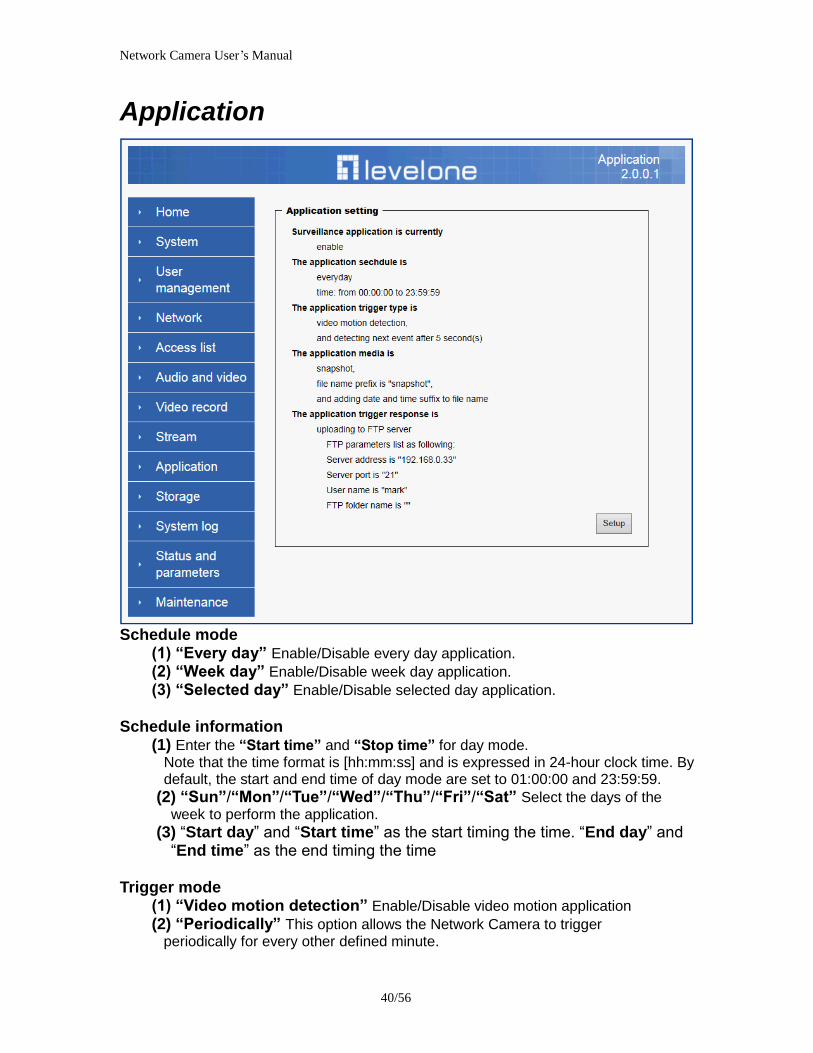
Network Camera Userrsquos Manual
4556
Syslog
The Network camera supports log the system messages on remote server The protocol is compliant to RFC 3164 If you have external Linux server with sys log service use ldquo-rrdquo option to turn on the facility for receiving log from remote machine Or you can use some software on Windows that is compliant to RFC 3164 An example is Kiwi Syslog Daemon Visit httpwwwkiwisyslogcomkiwi-syslog-daemon-overview Check ldquoSetuprdquo and ldquoEnablerdquo then input the ldquoIP addressrdquo and ldquoportrdquo number of the log server to enable the remote log facility In the ldquoCurrent logrdquo it displays the current system log file The content of the log provides useful information about configuration and connection after system boot- up
ldquofinishrdquo Click on this button to save modify settings
Network Camera Userrsquos Manual
4656
Status and Parameters
User can find a lot of information about the system such as ldquoUpnp port forwardingrdquo
ldquoTraversing NATrdquo ldquoPublic IPrdquo and so on User also can get the number of current viewer of the Network Camera here
Network Camera Userrsquos Manual
4756
Maintenance
1 ldquoReboot systemrdquo The ldquoRebootrdquo button will reboot the Network Camera Itrsquos useful while the Network Camera got problem 2 ldquoRestore systemrdquo Click on ldquoRestorerdquo button on the configuration page to restore the factory default settings Restore all settings to factory default except settings in ldquoNetwork type rdquo and ldquoRoot Passwordrdquo The system will restart and require the installer program to set up the network again
3 ldquoCalibraterdquo Recalibrate the auto focus position to the default range to recover the tolerance caused by some external forces 4 ldquoExportImport filerdquo -- Export setting backup file Click to export all parameters for the device and user-defined scripts
-- Upload setting backup file Click Browsehellip to upload a setting backup file Please note that the model and firmware version of the device should be the same as the setting backup file If you have set up a fixed IP or other special settings for your device it is not suggested to upload a settings backup file
4 ldquoUpgrade firmwarerdquo Select the firmware file and click upgrade button Please be aware that you should not turn off the power during updating the firmware and wait for finish message
Network Camera Userrsquos Manual
4856
Warning The upgrade firmware procedure cannot be interrupted If the power
andor network connection are broken during the procedure it might possibly cause serious damage to the Network Camera
Note When upgrade firmware please wait for 120~210 seconds and then you can connect to Network Camera again The system will restart and require the installer program to set up the network again
Network Camera Userrsquos Manual
4956
Appendix
A Troubleshooting amp Frequently Asked Questions Q1 Status led does not light up
A1 First make sure that「ConfigurationgtSystemgtTurn off the LED indicator」is disabled
If it is check the item and the led should light up Second if red led does not light up please check that the power adapter in the package is plugged correctly And last if green led does not light up please check that category 5 UTP cable is plugged correctly If the problem is still not solved please contact your dealer for further help
Q2 What kind of Ethernet cable is used by network camera
A2 The network Camera uses Category 5 UTP cable allowing 10 andor 100 Base-T networking
Q3 The Network Camera will be installed and work if a firewall exists on
the network
A3 There are two way to set up the IP camera at Internet (1) By UPnP Port Forwarding 1 Select an IP router It must support UPnP port forwarding and enable this function
first
2 Connect camera RJ45 cable to IP router and the router is also connected to Internet
3 Plug power cord to camera
4 Go to camera Network page Enable UPnP port forwarding
5 Check camera status we can see the ports had been successfully opened
Network Camera Userrsquos Manual
5056
6Type IP address8080 at browser Then you can see camera through Internet
7You can also type the ddns name at below label of camera on browser URL field For example you may type ah00001ip-discoverycom8080 (2) By Setting Port Forwarding Manually 1 Select a router Set the port forwarding as following
Network Camera Userrsquos Manual
5156
PS Port 80 is HTTP Port port 53 is stream port port 554 is RTSP port and port 443 is HTTPS port 2Go to camera Network page Disable UPnP port forwarding function
Network Camera Userrsquos Manual
5256
3 Type IP address at browser Then you can see camera through Internet
4 You can also type the ddns name at below label of camera on browser URL field For example you may type ah00001ip-discoverycom
Note The firewall software at PC may block the transfer of network camera Please remove or stop the kind software
Q4 How can I find the network camera in the local area network
A4 By using the IP Finder2 program or using UPnP to find it
Q5 IP Finder2 program cannot find Network Camera in the local area
network at first time
A5 Make sure the subnet of network camera is same as your PC If the local area network supports DHCP the camera is ldquoGet IP address automaticallyrdquo in the ldquoNetworkrdquo page default If the local area network does not support DHCP change your PC IP address to ldquo1921680xxxrdquo
Network Camera Userrsquos Manual
5356
Q6 How can I restore the network camera to default value
A6 Use a gem clip to press on the inside button Network camera begins to restore default value You can also press the button ldquoFactoryrdquo in ldquoMaintenancerdquo page to restore the default value
Q7 I cannot play the recorded video file
A7 Install the audio codec in the CD and use the Windows Media Player 10 or later to play the ASF or AVI file recorded by the network camera
Q8 Infrared led does not light up
A8 Check「ConfigurationgtAudio and VideogtInfrared LED Control」 is ldquoAutordquo or
ldquoManual》Turn onrdquo
Q9 The network camera cannot focus accurately
A9 (1) The lens is dirty or dust is attached Clean the lens with lens cleaner And then adjust the camera focus manually (2) The image may be out of focus If the object is too near move the object away from Network Camera
Q10 The cover of network camera is warm Is it normal
A10 Network camera is a precision device The internal material has the operational temperature and it is normal when user touch the cover feels warm It is recommended to put the network camera at aired place and not put at any other device
Q11 The process of upgrade firmware abort
A11 Contact your dealer for further help
Q12 Cannot access the login page and other web pages of Network
Network Camera Userrsquos Manual
5456
Camera from Internet Explorer
A12 bull May be due to the network cable Try correcting your network cable and configuration Test the network interface by connecting a local computer to the Network Camera via a crossover cable bull Make sure the Internet connection and setting is ok bull Make sure enter the IP address of Internet Explorer is correct If Network Camera has a dynamic address it may have changed since you last checked it bull Network congestion may prevent the web page appearing quickly Wait for a while The IP address and Subnet Mask of the PC and Network Camera must be in the same class of the private IP address on the LAN bull Make sure the http port used by the Network Camera default=80 is forward to the Network Camerarsquos private IP address bull The port number assigned in your Network Camera might not be available via Internet Check your ISP for available port bull The proxy server may prevent you from connecting directly to Network Camera set up not to use the proxy server bull Confirm that Default Gateway address is correct bull The router needs Port Forwarding feature Refer to your routers manual for details bull Packet Filtering of the router may prohibit access from an external network Refer to your routers manual for details bull Access Network Camera from the Internet with the global IP address of the router and port number of Network Camera bull Some routers reject the global IP address to access Network Camera on the same LAN Access with the private IP address and correct port number of Network Camera bull When you use DDNS you need to set Default Gateway and DNS server address bull If itrsquos not working after above procedure reset Network Camera to default setting and installed it again bull Maybe the IP Address of the Network Camera is already being used by another device or computer bull If the problem is not solved the Network Camera might be faulty Contact your dealer for further help
Network Camera Userrsquos Manual
5556
B Technical specifications
- System RAM 4G bit DDRⅢ
ROM 16MB Flash ROM
- Camera specification 127 inch color CMOS sensor Resolution 1920x1080 10LuxF20 AGC AWB AEC
- Infrared Led High power IR Leds 25~30 M visible AutoManual mode
- Lens 3X optical zoom lens auto iris auto focus f = 28~ 12mm F18 Fov(D) 136deg ~ 39deg
- Protocol TCPIP HTTPUDP SMTP FTP DDNS UPnP Telnet NTP PPPoE RTSP RTPRTCPDHCP and DNS
- Video Resolution Up to 30 frames at 176x144 Up to 30 frames at 320x240 Up to 30 frames at 640x480 Up to 30 frames at 1280x800 Up to 30 frames at 1280x1024 Up to 30 frames at 1920x1080
- Algorithm supported H264MPEG4MJPEG dual codec for streaming video JPEG for still image
- Audio AMRAACG711 External MIC input 2-way audio
- Physical 10 baseT100 baseT and 1000 baseT Fast
Ethernet auto negotiation
- Power Input 100-240VAC 5060Hz 07A Output 12VDC 15A Consumption Max 12 W Support 8023af compliant Power over Ethernet
- EMI amp Safety CE FCC
- Dimension Length 165mm Diameter 75mm
- Operating Environment Temperature -20 ~ 50
Humidity 85 RH
- Weight NET 600g With bracket 800g
Network Camera Userrsquos Manual
5656
Notification of Compliance Appendix C
Europe - EU Declaration of Conformity
For complete DoC please visit httpgloballevel1comdownloadsphpaction=init
GPL License Agreement GPL may be included in this product to view the GPL license agreement goes to httpdownloadlevel1comlevel1gplGPLpdf For GNU General Public License (GPL) related information please visit httpgloballevel1comdownloadsphpaction=init
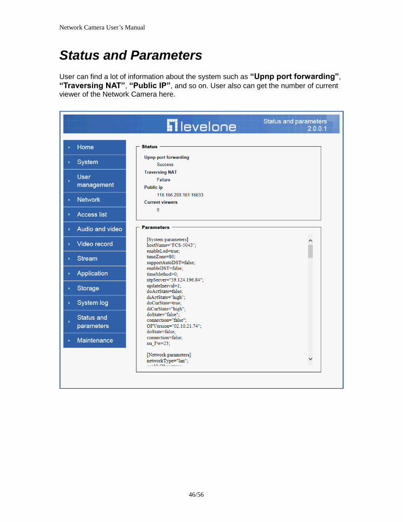
Network Camera Userrsquos Manual
4956
Appendix
A Troubleshooting amp Frequently Asked Questions Q1 Status led does not light up
A1 First make sure that「ConfigurationgtSystemgtTurn off the LED indicator」is disabled
If it is check the item and the led should light up Second if red led does not light up please check that the power adapter in the package is plugged correctly And last if green led does not light up please check that category 5 UTP cable is plugged correctly If the problem is still not solved please contact your dealer for further help
Q2 What kind of Ethernet cable is used by network camera
A2 The network Camera uses Category 5 UTP cable allowing 10 andor 100 Base-T networking
Q3 The Network Camera will be installed and work if a firewall exists on
the network
A3 There are two way to set up the IP camera at Internet (1) By UPnP Port Forwarding 1 Select an IP router It must support UPnP port forwarding and enable this function
first
2 Connect camera RJ45 cable to IP router and the router is also connected to Internet
3 Plug power cord to camera
4 Go to camera Network page Enable UPnP port forwarding
5 Check camera status we can see the ports had been successfully opened
Network Camera Userrsquos Manual
5056
6Type IP address8080 at browser Then you can see camera through Internet
7You can also type the ddns name at below label of camera on browser URL field For example you may type ah00001ip-discoverycom8080 (2) By Setting Port Forwarding Manually 1 Select a router Set the port forwarding as following
Network Camera Userrsquos Manual
5156
PS Port 80 is HTTP Port port 53 is stream port port 554 is RTSP port and port 443 is HTTPS port 2Go to camera Network page Disable UPnP port forwarding function
Network Camera Userrsquos Manual
5256
3 Type IP address at browser Then you can see camera through Internet
4 You can also type the ddns name at below label of camera on browser URL field For example you may type ah00001ip-discoverycom
Note The firewall software at PC may block the transfer of network camera Please remove or stop the kind software
Q4 How can I find the network camera in the local area network
A4 By using the IP Finder2 program or using UPnP to find it
Q5 IP Finder2 program cannot find Network Camera in the local area
network at first time
A5 Make sure the subnet of network camera is same as your PC If the local area network supports DHCP the camera is ldquoGet IP address automaticallyrdquo in the ldquoNetworkrdquo page default If the local area network does not support DHCP change your PC IP address to ldquo1921680xxxrdquo
Network Camera Userrsquos Manual
5356
Q6 How can I restore the network camera to default value
A6 Use a gem clip to press on the inside button Network camera begins to restore default value You can also press the button ldquoFactoryrdquo in ldquoMaintenancerdquo page to restore the default value
Q7 I cannot play the recorded video file
A7 Install the audio codec in the CD and use the Windows Media Player 10 or later to play the ASF or AVI file recorded by the network camera
Q8 Infrared led does not light up
A8 Check「ConfigurationgtAudio and VideogtInfrared LED Control」 is ldquoAutordquo or
ldquoManual》Turn onrdquo
Q9 The network camera cannot focus accurately
A9 (1) The lens is dirty or dust is attached Clean the lens with lens cleaner And then adjust the camera focus manually (2) The image may be out of focus If the object is too near move the object away from Network Camera
Q10 The cover of network camera is warm Is it normal
A10 Network camera is a precision device The internal material has the operational temperature and it is normal when user touch the cover feels warm It is recommended to put the network camera at aired place and not put at any other device
Q11 The process of upgrade firmware abort
A11 Contact your dealer for further help
Q12 Cannot access the login page and other web pages of Network
Network Camera Userrsquos Manual
5456
Camera from Internet Explorer
A12 bull May be due to the network cable Try correcting your network cable and configuration Test the network interface by connecting a local computer to the Network Camera via a crossover cable bull Make sure the Internet connection and setting is ok bull Make sure enter the IP address of Internet Explorer is correct If Network Camera has a dynamic address it may have changed since you last checked it bull Network congestion may prevent the web page appearing quickly Wait for a while The IP address and Subnet Mask of the PC and Network Camera must be in the same class of the private IP address on the LAN bull Make sure the http port used by the Network Camera default=80 is forward to the Network Camerarsquos private IP address bull The port number assigned in your Network Camera might not be available via Internet Check your ISP for available port bull The proxy server may prevent you from connecting directly to Network Camera set up not to use the proxy server bull Confirm that Default Gateway address is correct bull The router needs Port Forwarding feature Refer to your routers manual for details bull Packet Filtering of the router may prohibit access from an external network Refer to your routers manual for details bull Access Network Camera from the Internet with the global IP address of the router and port number of Network Camera bull Some routers reject the global IP address to access Network Camera on the same LAN Access with the private IP address and correct port number of Network Camera bull When you use DDNS you need to set Default Gateway and DNS server address bull If itrsquos not working after above procedure reset Network Camera to default setting and installed it again bull Maybe the IP Address of the Network Camera is already being used by another device or computer bull If the problem is not solved the Network Camera might be faulty Contact your dealer for further help
Network Camera Userrsquos Manual
5556
B Technical specifications
- System RAM 4G bit DDRⅢ
ROM 16MB Flash ROM
- Camera specification 127 inch color CMOS sensor Resolution 1920x1080 10LuxF20 AGC AWB AEC
- Infrared Led High power IR Leds 25~30 M visible AutoManual mode
- Lens 3X optical zoom lens auto iris auto focus f = 28~ 12mm F18 Fov(D) 136deg ~ 39deg
- Protocol TCPIP HTTPUDP SMTP FTP DDNS UPnP Telnet NTP PPPoE RTSP RTPRTCPDHCP and DNS
- Video Resolution Up to 30 frames at 176x144 Up to 30 frames at 320x240 Up to 30 frames at 640x480 Up to 30 frames at 1280x800 Up to 30 frames at 1280x1024 Up to 30 frames at 1920x1080
- Algorithm supported H264MPEG4MJPEG dual codec for streaming video JPEG for still image
- Audio AMRAACG711 External MIC input 2-way audio
- Physical 10 baseT100 baseT and 1000 baseT Fast
Ethernet auto negotiation
- Power Input 100-240VAC 5060Hz 07A Output 12VDC 15A Consumption Max 12 W Support 8023af compliant Power over Ethernet
- EMI amp Safety CE FCC
- Dimension Length 165mm Diameter 75mm
- Operating Environment Temperature -20 ~ 50
Humidity 85 RH
- Weight NET 600g With bracket 800g
Network Camera Userrsquos Manual
5656
Notification of Compliance Appendix C
Europe - EU Declaration of Conformity
For complete DoC please visit httpgloballevel1comdownloadsphpaction=init
GPL License Agreement GPL may be included in this product to view the GPL license agreement goes to httpdownloadlevel1comlevel1gplGPLpdf For GNU General Public License (GPL) related information please visit httpgloballevel1comdownloadsphpaction=init
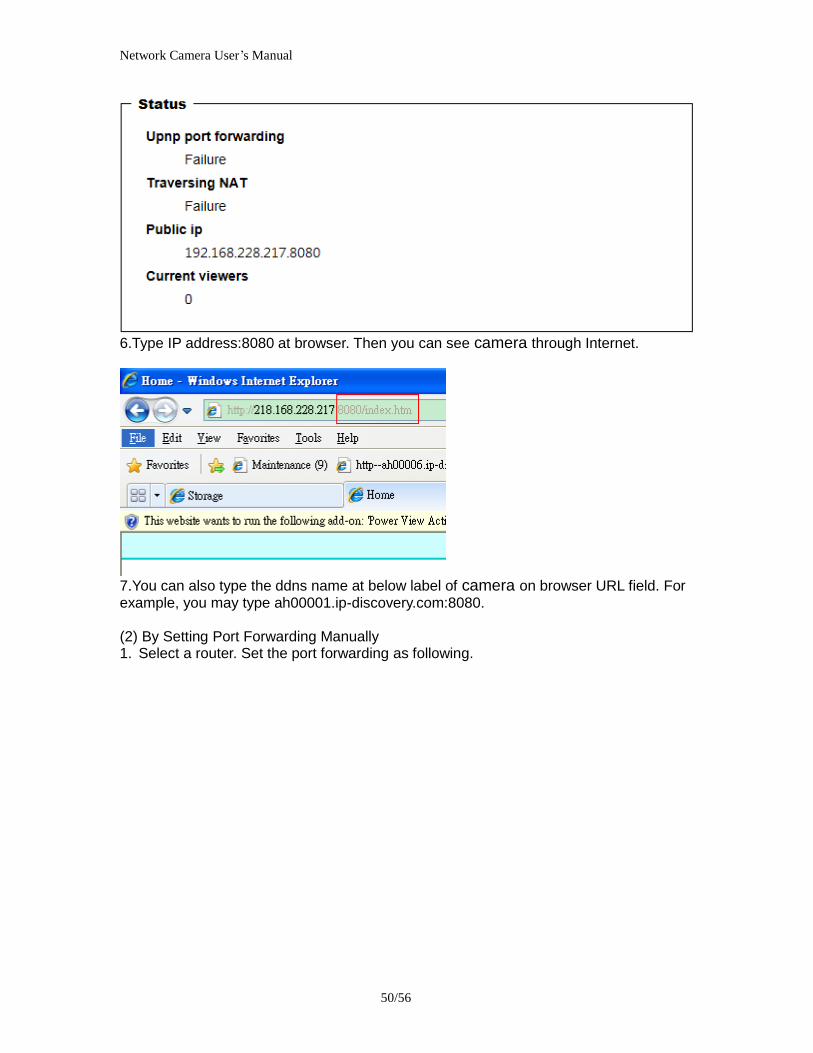
Network Camera Userrsquos Manual
5556
B Technical specifications
- System RAM 4G bit DDRⅢ
ROM 16MB Flash ROM
- Camera specification 127 inch color CMOS sensor Resolution 1920x1080 10LuxF20 AGC AWB AEC
- Infrared Led High power IR Leds 25~30 M visible AutoManual mode
- Lens 3X optical zoom lens auto iris auto focus f = 28~ 12mm F18 Fov(D) 136deg ~ 39deg
- Protocol TCPIP HTTPUDP SMTP FTP DDNS UPnP Telnet NTP PPPoE RTSP RTPRTCPDHCP and DNS
- Video Resolution Up to 30 frames at 176x144 Up to 30 frames at 320x240 Up to 30 frames at 640x480 Up to 30 frames at 1280x800 Up to 30 frames at 1280x1024 Up to 30 frames at 1920x1080
- Algorithm supported H264MPEG4MJPEG dual codec for streaming video JPEG for still image
- Audio AMRAACG711 External MIC input 2-way audio
- Physical 10 baseT100 baseT and 1000 baseT Fast
Ethernet auto negotiation
- Power Input 100-240VAC 5060Hz 07A Output 12VDC 15A Consumption Max 12 W Support 8023af compliant Power over Ethernet
- EMI amp Safety CE FCC
- Dimension Length 165mm Diameter 75mm
- Operating Environment Temperature -20 ~ 50
Humidity 85 RH
- Weight NET 600g With bracket 800g
Network Camera Userrsquos Manual
5656
Notification of Compliance Appendix C
Europe - EU Declaration of Conformity
For complete DoC please visit httpgloballevel1comdownloadsphpaction=init
GPL License Agreement GPL may be included in this product to view the GPL license agreement goes to httpdownloadlevel1comlevel1gplGPLpdf For GNU General Public License (GPL) related information please visit httpgloballevel1comdownloadsphpaction=init