PT-G7728/G7828 Quick Installation Guide
16
P/N: 1802077280413 *1802077280413* PT-G7728/G7828 Quick Installation Guide Version 1.3, January 2021 Technical Support Contact Information www.moxa.com/support 2021 Moxa Inc. All rights reserved.
Transcript of PT-G7728/G7828 Quick Installation Guide

P/N: 1802077280413
*1802077280413*
PT-G7728/G7828 Quick Installation Guide
Version 1.3, January 2021
Technical Support Contact Information www.moxa.com/support
2021 Moxa Inc. All rights reserved.

- 2 -
Package Checklist
Moxa’s PT-G7728/G7828 industrial rackmount switch is shipped with the following items. If any of these items are missing or damaged, please contact your customer service representative for assistance.
• 1 PT-G7728 or G7828 switch • USB cable (Type A male to Micro USB type B) • 2 protective caps for unused ports, 3 protective caps for unused USB
ports • 2 rackmount ears • Quick installation guide (printed) • Substance Disclosure Table • Product Certificate of Quality Inspection (Simplified Chinese) • Product Notices (Simplified Chinese) • Warranty card
NOTE You can find information and software downloads on the relevant product pages located on Moxa’s website: www.moxa.com
Default Settings
• Default IP address: 192.168.127.253 • Default Subnet Mask: 255.255.255.0 • Default Usernames: admin, user • Default Password: moxa
Panel Layouts
Front Panel
1. System status LEDs (from left to right) STATE LED indicator, MSTR/HEAD LED indicator, FAULT LED indicator, CPLR/Tail LED indicator, SYNC LED indicator
2. USB console port 3. 2 x 10/100/1000BaseT(X) and 2 x 100/1000Base SFP ports 4. 100/1000Base SFP port status LEDs 5. 10/100/1000BaseT(X) port status LEDs 6. Ethernet module slot 1 7. Ethernet module slot 2 8. Ethernet module slot 3 9. Ethernet module slot 4
10. Ethernet module slot 5 11. Ethernet module slot 6 12. Power module slot 1 13. Power module slot 2 14. Grounding screw

- 3 -
Rear View
1. USB console port 2. USB storage port 3. System LED indicators 4. Module and port LED indicators 5. Rest button
Dimensions
Unit: mm (inches)
Ethernet Modules
LM-7000H-4GTX LM-7000H-4TX
LM-7000H-4GSFP LM-7000H-4GPoE
LM-7000H-4PoE
- 4 -
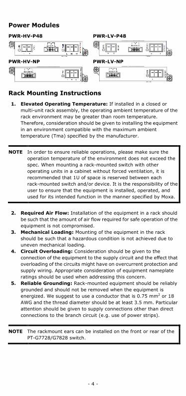
Power Modules
PWR-HV-P48 PWR-LV-P48
PWR-HV-NP PWR-LV-NP
Rack Mounting Instructions
1. Elevated Operating Temperature: If installed in a closed or multi-unit rack assembly, the operating ambient temperature of the rack environment may be greater than room temperature. Therefore, consideration should be given to installing the equipment in an environment compatible with the maximum ambient temperature (Tma) specified by the manufacturer.
NOTE In order to ensure reliable operations, please make sure the operation temperature of the environment does not exceed the spec. When mounting a rack-mounted switch with other operating units in a cabinet without forced ventilation, it is recommended that 1U of space is reserved between each rack-mounted switch and/or device. It is the responsibility of the user to ensure that the equipment is installed, operated, and used for its intended function in the manner specified by Moxa.
2. Required Air Flow: Installation of the equipment in a rack should
be such that the amount of air flow required for safe operation of the equipment is not compromised.
3. Mechanical Loading: Mounting of the equipment in the rack should be such that a hazardous condition is not achieved due to uneven mechanical loading.
4. Circuit Overloading: Consideration should be given to the connection of the equipment to the supply circuit and the effect that overloading of the circuits might have on overcurrent protection and supply wiring. Appropriate consideration of equipment nameplate ratings should be used when addressing this concern.
5. Reliable Grounding: Rack-mounted equipment should be reliably grounded and should not be removed when the equipment is energized. We suggest to use a conductor that is 0.75 mm2 or 18 AWG and the thread diameter should be at least 3.5 mm. Particular attention should be given to supply connections other than direct connections to the branch circuit (e.g. use of power strips).
NOTE The rackmount ears can be installed on the front or rear of the PT-G7728/G7828 switch.
- 5 -
ATTENTION
Safety First!
Be sure to disconnect the power cord before installing and/or wiring your Ethernet Switch. Calculate the maximum possible current in each power wire and common wire. Observe all electrical codes dictating the maximum current allowable for each wire size. If the current goes above the maximum ratings, the wiring could overheat, which can cause serious damage to your equipment.
WARNING
This is a Class 1 laser/LED product. Do not stare directly into the laser beam.
Connecting the Power Inputs
The PT-G7728/PT-G7828 switches support 4 types of power supply:
• PWR-HV-P48: one 110/220 VAC/VDC (90 to 264 VAC, 88 to 300 VDC), one 48VDC PoE power input for PoE+ ports.
• PWR-LV-P48: one 24/48 VDC (18 to 72 VDC), one 48 VDC PoE power input for PoE+ ports.
• PWR-HV-NP: one 110/220 VAC/VDC (90 to 264 VAC, 88 to 300 VDC). • PWR-LV-NP: one 24/48 VDC (18 to 72 VDC).
For the PWR-HV-P48, the 110/220 VAC/VDC power supplies provide power to the switch. Separate 48 VDC power supplies are required to provide power to 12 PoE+ ports (50 to 57 VDC is recommended for IEEE 802.3at devices).
For the PWR-LV-P48 models, the 24/48 VDC power supplies provide power to the switch. Separate 48 VDC power supplies are required to provide power to 12 PoE+ ports (50 to 57 VDC is recommended for IEEE 802.3at devices).
In order to provide power to 24 PoE+ ports, two power modules should be used.
For the PWR-HV-NP, the 110/220 VAC/VDC power supplies provide power to the switch.
For the PWR-LV-NP, the 24/48 VDC power supplies provide power to the switch.
- 6 -
Wiring Requirements
WARNING
Do not disconnect modules or wires unless power has been switched off or the area is known to be non-hazardous. The device may only be connected to the supply voltage shown on the type plate. The device is designed for operation with a Safety Extra-Low Voltage (SELV) or an isolated power supply, which means that they may only be connected to the supply voltage connections and to the signal contact with a SELV or an isolated power supply in compliance with IEC 60950-1/EN 60950-1.
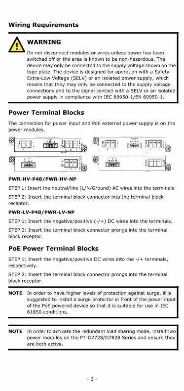
Power Terminal Blocks
The connection for power input and PoE external power supply is on the power modules.
PWR-HV-P48/PWR-HV-NP
STEP 1: Insert the neutral/line (L/N/Ground) AC wires into the terminals.
STEP 2: Insert the terminal block connector into the terminal block receptor.
PWR-LV-P48/PWR-LV-NP
STEP 1: Insert the negative/positive (-/+) DC wires into the terminals.
STEP 2: Insert the terminal block connector prongs into the terminal block receptor.
PoE Power Terminal Blocks
STEP 1: Insert the negative/positive DC wires into the -/+ terminals, respectively.
STEP 2: Insert the terminal block connector prongs into the terminal block receptor.
NOTE In order to have higher levels of protection against surge, it is suggested to install a surge protector in front of the power input of the PoE powered device so that it is suitable for use in IEC 61850 conditions.
NOTE In order to activate the redundant load sharing mode, install two power modules on the PT-G7728/G7828 Series and ensure they are both active.

- 7 -
NOTE The reverse power input connection will not activate the device or PoE input. In addition, the PoE will only activate when the system power input is installed on the same power unit.
Wiring the Relay Contact
Each power module has one relay output that can provide two types of relay output. Refer to the table below for detailed information.
The relay contact is used to detect user-configured events. Two wires are attached to the relay pins with normally close and normally open options.
FAULT: The relay contact of the 3-pin terminal block connector is used to detect user-configured events. The module provides normally open and normally closed circuits depending on what the user chooses. For pin definitions refer to the table below.
Relay connection Power on state Event trigger NO and COM Closed circuit Open circuit NC and COM Open circuit Closed circuit
NOTE When wiring the relay contact, we suggest using the cable type - AWG (American Wire Gauge) 16-24 (1.31-0.205mm2) and the corresponding pin type cable terminals. The connector must be able to withstand torque at maximum 5 pound-inches. The rated temperature of wiring should be at least 105°C.
Install/Remove the Ethernet module
The Ethernet modules are hot-swappable. You have the option to mount or remove the Ethernet module while the device is operating.
The installation procedure is as follows:
1. Insert the Ethernet module straight into the slot 2. Fasten the module to the device by tightening the 2 screws. The
tightening torque is 3.5 kgf-cm (0.35 Nm)
The removal procedure is as follows:
1. Loosen the 2 screws of the module 2. Pull the module out of the slot 3. Insert the dummy module in to the slot in order to have better
protection against dust and EMI 4. Fasten the dummy module using 2 screws. The tightening torque is
4 kgf-cm (0.40 Nm)
Install/Remove the Power module
The power supply units are hot-swappable. You have the option to mount or remove the power supply units while the device is operating.
The installation procedure is as follows:
1. Insert the power unit straight into the slot 2. Fasten the unit to the device by tightening the 2 screws. The
tightening torque is 3.5 kgf-cm (0.35 Nm)
The removal procedure is as follows:

- 8 -
1. Loosen the 2 screws of the module 2. Pull the module out of the slot 3. Insert the dummy module in to the slot in order to have better
protection against dust and EMI. 4. Fasten the dummy module using 2 screws. The tightening torque is
4 kgf-cm (0.40 Nm)
NOTE If one of the modules is removed from the device, it is advisable to insert a dummy module in order to provide better protection against dust and EMI.
Grounding the Moxa Industrial Rackmount Switch
Grounding and wire routing help limit the effects of noise due to electromagnetic interference (EMI). Run the ground connection from the ground screw to the grounding surface prior to connecting devices.
NOTE Using a shielded cable achieves better electromagnetic resistance.
USB Console Connection
The switch has two types of USB port, micro USB-B console port and type A USB host port. Use a USB cable (type A male to Micro USB-B male) to connect the USB-serial console port to your PC's COM port, and install the USB driver (available on Moxa Website) onto the PC. You can then use a console terminal program, such as Moxa’s PComm Terminal Emulator, to access the console configuration utility of the switch.
USB Storage Connection
The USB storage port is on the rear panel of the PT-G7728/G7828 switch. (Type A connector; see the diagram below for pinout assignments). Use Moxa’s ABC-02-USB automatic backup configurator to connect to the PT-G7728/G7828 USB storage port in order to perform configuration backup, firmware upgrade, or system log file backup.
Pin Description 1 VCC (+5V) 2 D- (Data-) 3 D+ (Data+) 4 GND (Ground)
The Reset Button
The reset button can perform two functions. One is to reset the PT-G7728/G7828 switch back to factory default settings and the other is to perform a quick back up of configuration and log files to the ABC-02-USB automatic backup configurator.
Reset to Factory Default Settings
Depress the Reset button for five seconds to load the factory default settings. Use a pointed object, such as a straightened paper clip or toothpick, to depress the Reset button. When you do so, the STATE LED will start to blink about once per second. Continue to depress the STATE
- 9 -
LED until it begins blinking more rapidly; this indicates that the button has been depressed for five seconds and you can release the Reset button to load factory default settings.
NOTE DO NOT power off the switch when loading default settings.
Configuration and Log Files Back Up
When the ABC-02-USB is connected to the PT-G7728/G7828 switch, the reset button allows for a quick back up of configuration and event logs to the ABC-02-USB. Press the reset button to start backing up the current system configuration files and event logs to the ABC-02-USB.
NOTE When the ABC-02 is plugged in, you cannot reset to factory default by pressing the reset button.
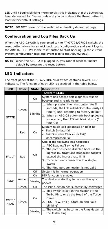
LED Indicators
The front panel of the PT-G7728/G7828 switch contains several LED indicators. The function of each LED is described in the table below.
LED Color State Description System LEDs
STATE
Green
On System has passed self-diagnosis test on boot-up and is ready to run
Blinking
1. When pressing the reset button for 5 seconds, the LED will blink continuously (1 time/s) until resetting to factory default
2. When an ABC-02 automatic backup device is detected, the LED will blink slowly (1 time/2s)
Red On
System failed self-diagnosis on boot up. • Switch Initiate fail • Fail Firmware Checksum Fail/
Uncompressed Fail
FAULT Red On
One of the following has happened: 1. ABC Loading/Saving Failure 2. The port has been disabled because the
ingress multicast and broadcast packets exceed the ingress rate limit
3. Incorrect loop connection in a single switch
4. The Ring port connection is not valid Off System is in normal operation
SYNC Amber
On PTP function is enabled
Blinking The device is starting to receive the sync packet
Green On The PTP function has successfully converged
MSTR/ HEAD
Green On
1. This switch is set as the Master of the Turbo Ring, or as the Head of the Turbo Chain.
2. POST H.W. Fail (+State on and Fault blinking)
Blinking 1. The switch has become the Ring Master of
the Turbo Ring.
- 10 -
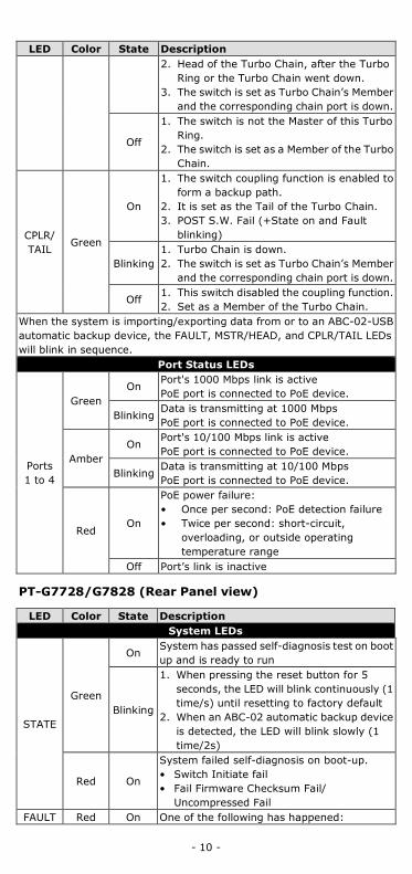
LED Color State Description 2. Head of the Turbo Chain, after the Turbo
Ring or the Turbo Chain went down. 3. The switch is set as Turbo Chain’s Member
and the corresponding chain port is down.
Off
1. The switch is not the Master of this Turbo Ring.
2. The switch is set as a Member of the Turbo Chain.
CPLR/ TAIL
Green
On
1. The switch coupling function is enabled to form a backup path.
2. It is set as the Tail of the Turbo Chain. 3. POST S.W. Fail (+State on and Fault
blinking)
Blinking 1. Turbo Chain is down. 2. The switch is set as Turbo Chain’s Member
and the corresponding chain port is down.
Off 1. This switch disabled the coupling function. 2. Set as a Member of the Turbo Chain.
When the system is importing/exporting data from or to an ABC-02-USB automatic backup device, the FAULT, MSTR/HEAD, and CPLR/TAIL LEDs will blink in sequence.
Port Status LEDs
Ports 1 to 4
Green On
Port's 1000 Mbps link is active PoE port is connected to PoE device.
Blinking Data is transmitting at 1000 Mbps PoE port is connected to PoE device.
Amber On
Port's 10/100 Mbps link is active PoE port is connected to PoE device.
Blinking Data is transmitting at 10/100 Mbps PoE port is connected to PoE device.
Red On
PoE power failure: • Once per second: PoE detection failure • Twice per second: short-circuit,
overloading, or outside operating temperature range
Off Port’s link is inactive
PT-G7728/G7828 (Rear Panel view)
LED Color State Description System LEDs
STATE
Green
On System has passed self-diagnosis test on boot up and is ready to run
Blinking
1. When pressing the reset button for 5 seconds, the LED will blink continuously (1 time/s) until resetting to factory default
2. When an ABC-02 automatic backup device is detected, the LED will blink slowly (1 time/2s)
Red On
System failed self-diagnosis on boot-up. • Switch Initiate fail • Fail Firmware Checksum Fail/
Uncompressed Fail FAULT Red On One of the following has happened:
- 11 -
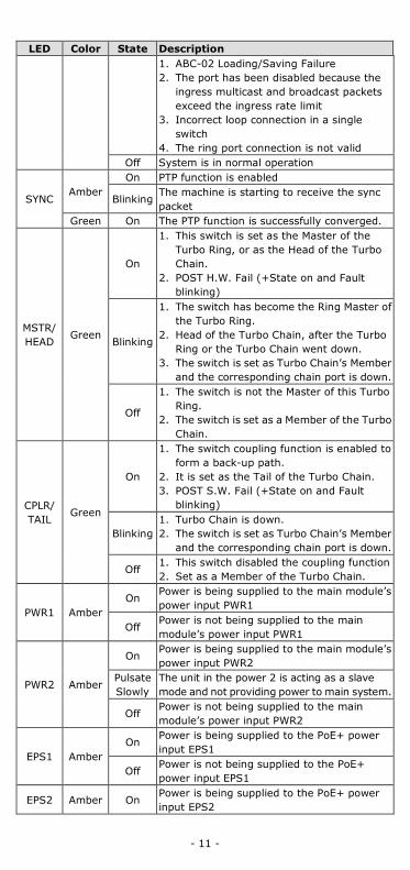
LED Color State Description 1. ABC-02 Loading/Saving Failure 2. The port has been disabled because the
ingress multicast and broadcast packets exceed the ingress rate limit
3. Incorrect loop connection in a single switch
4. The ring port connection is not valid Off System is in normal operation
SYNC Amber
On PTP function is enabled
Blinking The machine is starting to receive the sync packet
Green On The PTP function is successfully converged.
MSTR/ HEAD
Green
On
1. This switch is set as the Master of the Turbo Ring, or as the Head of the Turbo Chain.
2. POST H.W. Fail (+State on and Fault blinking)
Blinking
1. The switch has become the Ring Master of the Turbo Ring.
2. Head of the Turbo Chain, after the Turbo Ring or the Turbo Chain went down.
3. The switch is set as Turbo Chain’s Member and the corresponding chain port is down.
Off
1. The switch is not the Master of this Turbo Ring.
2. The switch is set as a Member of the Turbo Chain.
CPLR/ TAIL
Green
On
1. The switch coupling function is enabled to form a back-up path.
2. It is set as the Tail of the Turbo Chain. 3. POST S.W. Fail (+State on and Fault
blinking)
Blinking 1. Turbo Chain is down. 2. The switch is set as Turbo Chain’s Member
and the corresponding chain port is down.
Off 1. This switch disabled the coupling function 2. Set as a Member of the Turbo Chain.
PWR1 Amber On
Power is being supplied to the main module’s power input PWR1
Off Power is not being supplied to the main module’s power input PWR1
PWR2 Amber
On Power is being supplied to the main module’s power input PWR2
Pulsate Slowly
The unit in the power 2 is acting as a slave mode and not providing power to main system.
Off Power is not being supplied to the main module’s power input PWR2
EPS1 Amber On
Power is being supplied to the PoE+ power input EPS1
Off Power is not being supplied to the PoE+ power input EPS1
EPS2 Amber On Power is being supplied to the PoE+ power input EPS2
- 12 -
LED Color State Description
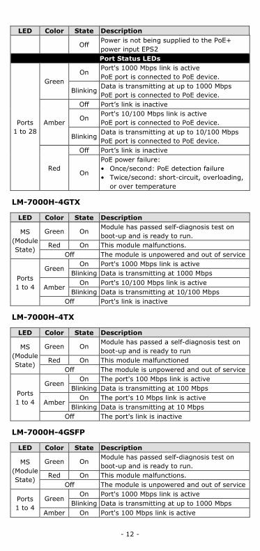
Off Power is not being supplied to the PoE+ power input EPS2 Port Status LEDs
Ports 1 to 28
Green On
Port's 1000 Mbps link is active PoE port is connected to PoE device.
Blinking Data is transmitting at up to 1000 Mbps PoE port is connected to PoE device.
Amber
Off Port’s link is inactive
On Port's 10/100 Mbps link is active PoE port is connected to PoE device.
Blinking Data is transmitting at up to 10/100 Mbps PoE port is connected to PoE device.
Red
Off Port’s link is inactive
On
PoE power failure: • Once/second: PoE detection failure • Twice/second: short-circuit, overloading,
or over temperature
LM-7000H-4GTX
LED Color State Description
MS (Module State)
Green On Module has passed self-diagnosis test on boot-up and is ready to run.
Red On This module malfunctions. Off The module is unpowered and out of service
Ports 1 to 4
Green On Port's 1000 Mbps link is active
Blinking Data is transmitting at 1000 Mbps
Amber On Port's 10/100 Mbps link is active
Blinking Data is transmitting at 10/100 Mbps Off Port's link is inactive
LM-7000H-4TX
LED Color State Description
MS (Module State)
Green On Module has passed a self-diagnosis test on boot-up and is ready to run
Red On This module malfunctioned Off The module is unpowered and out of service
Ports 1 to 4
Green On The port's 100 Mbps link is active
Blinking Data is transmitting at 100 Mbps
Amber On The port's 10 Mbps link is active
Blinking Data is transmitting at 10 Mbps Off The port's link is inactive
LM-7000H-4GSFP
LED Color State Description
MS (Module State)
Green On Module has passed self-diagnosis test on boot-up and is ready to run.
Red On This module malfunctions. Off The module is unpowered and out of service
Ports 1 to 4
Green On Port's 1000 Mbps link is active
Blinking Data is transmitting at up to 1000 Mbps Amber On Port's 100 Mbps link is active

- 13 -
LED Color State Description Blinking Data is transmitting at up to 10/100 Mbps
Off Port's link is inactive
LM-7000H-4GPoE
LED Color State Description
MS (Module State)
Green On Module has passed self-diagnosis test on boot-up and is ready to run.
Red On This module malfunctions. Off The module is unpowered and out of service
EPS Amber On
External power supply is working for PoE+ power output
Off External power supply is not working for PoE+ power output
Ports 1 to 4
Green On Port's 1000 Mbps link is active
Blinking Data is transmitting at 1000 Mbps
Amber On Port's 10/100 Mbps link is active
Blinking Data is transmitting at 10/100 Mbps Off Port's link is inactive
PoE/ PoE+ Ports 1 to 4
Green On PoE port is connected to PoE device, using the 802.3at standard.
Amber On PoE port is connected to PoE device, using the 802.3af standard.
Red On
PoE power failure: • Once/second: PoE detection failure • Twice/second: short-circuit, overloading,
or over temperature
LM-7000H-4PoE
LED Color State Description
MS (Module State)
Green On Module has passed a self-diagnosis test on boot-up and is ready to run
Red On This module malfunctions Off The module is unpowered and out of service
EPS Amber On
The external power supply is working for PoE+ power output
Off The external power supply is not working for PoE+ power output
Ports 1 to 4
Green On The port's 100 Mbps link is active
Blinking Data is transmitting at 100 Mbps
Amber On The port's 10 Mbps link is active
Blinking Data is transmitting at 10 Mbps Off The port's link is inactive
PoE/ PoE+
Ports 1 to 4
Green On The PoE port is connected to a PoE device, using the 802.3at standard.
Amber On
The PoE port is connected to a PoE device, using the 802.3af standard.
Blinking The PoE power has been shut off because of low power budget
Red On
PoE power failure: • Once/second: PoE detection failure • Twice/second: short-circuit, overloading, or outside acceptable temperature ranges
- 14 -
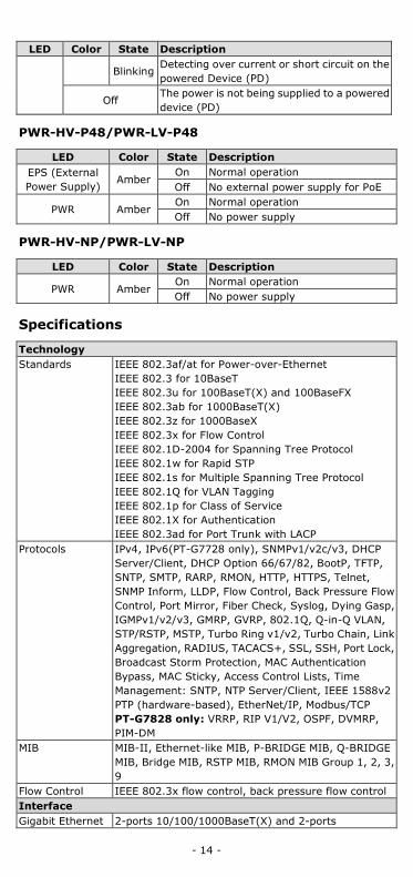
LED Color State Description
Blinking Detecting over current or short circuit on the powered Device (PD)
Off The power is not being supplied to a powered device (PD)
PWR-HV-P48/PWR-LV-P48
LED Color State Description EPS (External Power Supply)
Amber On Normal operation Off No external power supply for PoE
PWR Amber On Normal operation Off No power supply
PWR-HV-NP/PWR-LV-NP
LED Color State Description
PWR Amber On Normal operation Off No power supply
Specifications
Technology Standards IEEE 802.3af/at for Power-over-Ethernet
IEEE 802.3 for 10BaseT IEEE 802.3u for 100BaseT(X) and 100BaseFX IEEE 802.3ab for 1000BaseT(X) IEEE 802.3z for 1000BaseX IEEE 802.3x for Flow Control IEEE 802.1D-2004 for Spanning Tree Protocol IEEE 802.1w for Rapid STP IEEE 802.1s for Multiple Spanning Tree Protocol IEEE 802.1Q for VLAN Tagging IEEE 802.1p for Class of Service IEEE 802.1X for Authentication IEEE 802.3ad for Port Trunk with LACP
Protocols IPv4, IPv6(PT-G7728 only), SNMPv1/v2c/v3, DHCP Server/Client, DHCP Option 66/67/82, BootP, TFTP, SNTP, SMTP, RARP, RMON, HTTP, HTTPS, Telnet, SNMP Inform, LLDP, Flow Control, Back Pressure Flow Control, Port Mirror, Fiber Check, Syslog, Dying Gasp, IGMPv1/v2/v3, GMRP, GVRP, 802.1Q, Q-in-Q VLAN, STP/RSTP, MSTP, Turbo Ring v1/v2, Turbo Chain, Link Aggregation, RADIUS, TACACS+, SSL, SSH, Port Lock, Broadcast Storm Protection, MAC Authentication Bypass, MAC Sticky, Access Control Lists, Time Management: SNTP, NTP Server/Client, IEEE 1588v2 PTP (hardware-based), EtherNet/IP, Modbus/TCP PT-G7828 only: VRRP, RIP V1/V2, OSPF, DVMRP, PIM-DM
MIB MIB-II, Ethernet-like MIB, P-BRIDGE MIB, Q-BRIDGE MIB, Bridge MIB, RSTP MIB, RMON MIB Group 1, 2, 3, 9
Flow Control IEEE 802.3x flow control, back pressure flow control Interface Gigabit Ethernet 2-ports 10/100/1000BaseT(X) and 2-ports
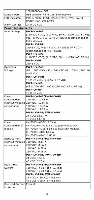
- 15 -
100/1000Base SFP Console Port USB console (Micro USB-B connector) LED Indicators PWR1, PWR2, EPS1, EPS2, STATE, SYNC, FAULT,
MSTR/HEAD, CPLR/TAIL Alarm Contact 2A @ 30 VDC Power Requirements Input Voltage PWR-HV-P48:
(110/220 VDC), (110 VAC, 60 Hz), (220 VAC, 50 Hz), PoE: 48 VDC, 8 A (53 to 57 VDC is recommended of PoE+ device) PWR-LV-P48: 24/48 VDC, PoE: 48 VDC, 8 A (53 to 57 VDC is recommended of PoE+ device) PWR-HV-NP: (110/220 VDC), (110 VAC, 60 Hz), (220 VAC, 50 Hz) PWR-LV-NP: 24/48 VDC
Operating Voltage
PWR-HV-P48: (88 to 300 VDC), (90 to 264 VAC, 47 to 63 Hz), PoE: 46 to 57 VDC PWR-LV-P48: 18 to 72 VDC, PoE: 46 to 57 VDC PWR-HV-NP: (88 to 300 VDC), (90 to 264 VAC, 47 to 63 Hz) PWR-LV-NP: 18 to 72 VDC
Power Consumption (without modules consumption)
PWR-HV-P48/PWR-HV-NP 110 VDC: 12.43 W 220 VDC: 12.87 W 110 VAC: 13.42 W 220 VAC: 14.08 W PWR-LV-P48/PWR-LV-NP 24 VDC: 12.67 W 48 VDC: 13.2 W
Power Consumption of module
LM-7000H-4GTX: 3.63 W LM-7000H-4GPoE: 3.80 W (w/o PoE output) LM-7000H-4GSFP: 1.56 W (w/o SFP modules) LM-7000H-4TX: 1.85 W LM-7000H-4PoE: 1.85 W
Input Current (without modules consumption)
PWR-HV-P48/PWR-HV-NP 110 VDC: 0.11 A 220 VDC: 0.06 A 110 VAC: 0.29 A 220 VAC: 0.18 A PWR-LV-P48/ PWR-LV-NP 24 VDC: 0.53 A 48 VDC: 0.28 A
Peak Inrush Current
PWR-HV-P48/PWR-HV-NP 110 VAC: < 10 A (t > 0.1 ms) 220 VAC: < 20 A (t > 0.1 ms) PWR-LV-P48/PWR-LV-NP 24 VDC: < 20 A (t > 0.1 ms) 48 VDC: < 20 A (t > 0.1 ms)
Overload Current Protection
Present

- 16 -
Reverse Polarity Protection
Present
Physical Characteristics Housing IP30 protection Dimensions 443 x 44 x 280 mm (17.32 x 1.37 x 11.02 in) Weight PT-G7728/G7828: 3.08 kg (6.78 lb)
LM-7000H-4GSFP: 0.30 kg (0.66 lb) LM-7000H-4GTX: 0.24 kg (0.53 lb) LM-7000H-4TX: 0.24 kg (0.53 lb) LM-7000H-4GPoE: 0.31 kg (0.69 lb) LM-7000H-4PoE: 0.31 kg (0.69 lb) PWR-HV-P48/PWR-LV-P48: 0.36 kg (0.79 lb) PWR-HV-NP/PWR-LV-NP: 0.34 kg (0.75 lb)
Installation 19” rack mounting Environmental Limits Operating Temp. -40 to 85°C (-40 to 185°F) Storage Temp. -40 to 85°C (-40 to 185°F) Ambient Relative Humidity
5 to 95% (non-condensing)
Note: This equipment is intended for use in a Pollution Degree 2 industrial environment, and for use in overvoltage Category II applications. The class of equipment is class I base on IEC 60950-1. Standards and Certifications Safety UL 62368-1, EN 62368-1 (LVD) EMC EN 55024, 55032 EMI CISPR 22, FCC Part 15B Class A EMS IEC 61000-4-2 ESD: Contact: 8 kV; Air: 15 kV
IEC 61000-4-3 RS: 80MHz to 1GHz: 20 V/m IEC 61000-4-4 EFT: Power: 4 kV; Signal: 4 kV IEC 61000-4-5 Surge: Power 4 kV; Signal: 4 kV IEC 61000-4-6 CS: 10V IEC 61000-4-8
Note: For better conductive radiation immunity, it is recommended to use a STP cable and install a surge protector at the PoE power input: EPS. Rail Traffic EN 50121-4 Substation IEC-61850-3 ed2 class2, IEEE 1613 class2 Warranty Warranty Period 5 years Details See www.moxa.com/warranty
Restricted Access Locations
• This equipment is intended to be used in Restricted Access Locations, such as a computer room, with access limited to service personnel or users who have been instructed on how to handle the metal chassis of equipment that is very hot. The location should only be accessible with a key or through a security system.
• External metal parts of this equipment are extremely hot. Before touching the equipment, you must take special precautions to protect your hands and body from serious injury.