Display system having electrode modulation to alter a state of an ...

Front. Comput. Sci., 2021, 15(3): 153703https://doi.org/10.1007/s11704-019-8265-3
Psycho-visual modulation based information display: introductionand survey
Ning LIU1,∗, Zhongpai GAO2,∗, Jia WANG3, Guangtao ZHAI 3
1 Cooperative Medianet Innovation Center, Shanghai Jiao Tong University, Shanghai 200240, China2 MoE Key Lab of Artificial Intelligence, AI Institute, Shanghai Jiao Tong University, Shanghai 200240, China
3 Institute of Image Communication and Network Engineering, Shanghai Jiao Tong University, Shanghai 200240, China
c© Higher Education Press 2020
Abstract Industry and academia have been making great ef-forts in improving refresh rates and resolutions of display de-vices to meet the ever increasing needs of consumers for bettervisual quality. As a result, many modern displays have spatialand temporal resolutions far beyond the discern capability ofhuman visual systems. Thus, leading to the possibility of usingthose display-eye redundancies for innovative usages. Tempo-ral/spatial psycho-visual modulation (TPVM/SPVM) was pro-posed to exploit those redundancies to generate multiple visualpercepts for different viewers or to transmit non-visual data tocomputing devices without affecting normal viewing. This pa-per reviews the STPVM technology from both conceptual andalgorithmic perspectives, with exemplary applications in multi-view display, display with visible light communication, etc.Some possible future research directions are also identified.
Keywords information display, human visual system, spatialfrequency, temporal frequency, non-negative matrix decompo-sition
1 IntroductionTemporal psycho-visual modulation (TPVM) [1] was proposedas an information display technology using the interplay ofsignal processing, optoelectronics, and psychophysics. TPVMaims to generate multiple visual percepts for different viewerson a common exhibition medium concurrently. The rationalebehind TPVM is that, on one hand, the human visual system(HVS) cannot resolve temporally rapidly changing optical sig-nals beyond the flicker fusion frequency (about 60 Hz [2, 3]for most people). On the other hand, nowadays, modern dis-plays can work at 120 Hz or even higher refresh rates. For ex-ample, the pattern rate of the spatial light modulator in digitallight processing (DLP) technology is up to 32 kHz [4]. Thusa high-speed display can offer much more visual stimuli thanthat viewer can assimilate. Therefore, a single display can havepsycho-visual redundancy to generate multiple visual perceptsfor different viewers simultaneously.
Received August 1, 2018; accepted March 5, 2019
E-mail: [email protected]∗These authors contributed equally to this work
Time multiplexing is a straightforward way of exploitingthe psycho-visual redundancy of high-speed displays. NVIDIA3D Vision is a stereoscopic gaming technology developed byNVIDIA, which consists of liquid crystal (LC) shutter glassesand driver software [5]. In NVIDIA 3D Vision, left and rightviews are presented in time-interleaved steps using synchro-nized shutter glasses. Sony’s dual-view technology presentstwo views for two participants on the same screen in disjointtime slots [6]. However, time multiplexing has three disadvan-tages. First, time multiplexing is not efficient enough since itcompletely ignores the statistical redundancy among output im-ages. Second, the image formed by the eyes without shutter de-vices is mixed by the multiple views, making it visually unap-pealing. Third, the light influx of each view decreases linearlywhen the number of different views increases.
As a more advanced solution, TPVM technology utilizesboth psycho-visual redundancy of displays and statistical re-dundancy of visual signals sufficiently using temporal modula-tion. TPVM can be implemented by a combination of a high-speed display and a pair of active LC glasses synchronized withthe display. LC glasses are light blockage devices that controlthe amount of incoming light passing through and entering theviewer’s eyes. In contrast, the shutter glasses of time multiplex-ing only have two states: passing through all the light whenthe shutter is open or blocking all the light when it is closed.A TPVM based display device broadcasts a set of images (i.e.,called atom frames) at a speed higher than the flicker fusion fre-quency. The atom frames are then weighted by LC shutters thatare synchronized with the display before entering HVSs andintegrating into some desired visual signals. Therefore, throughdifferent viewing devices (e.g., different weighted LC glasses),people can see different images on the same display.
Spatial psycho-visual modulation (SPVM) extends the ideaof TPVM to the spatial or pixel domain. Nowadays modern dis-plays can have a pixel density that is beyond the resolving abil-ity of the human eyes, e.g., the retinal display [2]. The study [7]indicates that an unaided human eye cannot differentiate detailbeyond 300 PPI (pixels per inch) at the best viewing distance.We can, therefore, exploit the spatial redundancy of screens togenerate multiple visual percepts concurrently. For example, an

2 Front. Comput. Sci., 2021, 15(3): 153703
interlaced-polarized display can broadcast out multiple imagesto different viewers. The scan lines of the display are dividedinto different polarized directions. The desired image can beviewed through a pair of matched polarized glasses.
It is a further natural extension to combine TPVM and SPVMby exploiting both spatial and temporal redundancies of thedisplay device, which is called spatial-temporal psycho-visualmodulation (STPVM), to provide even more views simultane-ously.
Some multiview display techniques were proposed over theyears. For examples, PiVOT [8] is a tabletop system aimed atsupporting mixed-focus collaborative tasks. Tensor displays [9]are a family of compressive and multi-layer displays by in-troducing a sophisticated hardware solution. A multi-viewertabletop autostereoscopic display [10] and MUSTARD [11] in-spired by the “Random Hole Display” design [12] are spacemultiplexing-based techniques. Polarization field displays [13]use multi-layered LCDs for automultiscopic display. However,these multiview display techniques need sophisticated hard-ware while TPVM just relies on off-the-shelf displays.
Based on the unique ability of TPVM or SPVM or STPVMthat can generate different and interference-free views on asingle display concurrently, some applications have been pro-posed and implemented on consumer-level off-the-shelf dis-plays. The applications can be categorized into two kinds: First,the psycho-visual redundancy of display devices can be used togenerate multiple visual percepts for different viewers, with andwithout viewing devices. Second, the redundancy can be usedfor data transmission to computing devices without sacrificingthe visual quality, which is in fact a kind of visible light com-munication (VLC).
Multiple visual percepts related applications include themultiple-exhibition on a lone display (MELD) system pre-sented in [14]. MELD can be used in multiuser collaborative vi-sualization and multiuser virtual reality (VR) for medical appli-cations. In [15–18], backward-compatible stereoscopic displaytechnology was proposed. The display system exhibited both3D and 2D views of a scene simultaneously on a single display.Thus, viewers wearing 3D glasses perceived a stereoscopic im-age and viewers without 3D glasses perceived a conventional2D image without ghost artifacts [19, 20]. Applications in in-formation security display systems were proposed in [21] usingTPVM and in [22] using SPVM. The information security dis-play was also deployed on android devices [23] and portablescreens [24]. Simultaneous dual- and triple-subtitles exhibitionsystems were introduced in [25] and [26], respectively. A dual-view oracle bone script recognition system [27] and a dual-viewmedical image visualization prototype system [28] were intro-duced. Moreover, [29] proposed an advanced projector solu-tion using TPVM, which can provide hidden information (e.g.,speech notes) to the speaker and also protect the speaker’s eyesfrom being exposed to the strong projector light.
Applications of data transmission on display include thecamcorder piracy protection solution for movie theaters pre-sented in [30–32]. A novel way of embedding quick response(QR) codes on digital screens, called invisible QR codes wasproposed [33]. Invisible QR codes embedded on a screen areperceptually transparent to humans but easily detectable by mo-
bile devices. Invisible QR codes were used for augmented re-ality as presented in [34]. Invisible QR codes have also beenimplemented in the spatial domain using polarization [35]. Sim-ilarly, ImplicitCode was proposed in [36], which is a high-ratevisual codes that can be hidden inside regular videos. Visiblelight communication systems were proposed in [37–40] so thatthe display can send data to cameras and without affecting nor-mal viewing. [41] introduced a flashlight system to aid visuallyimpaired people. The flashlight projects structure light in visi-ble spectrum using TPVM to minimize the visual disturbanceto bystanders, and a camera uses structure light to recognizethe road flatness (e.g., smooth road, up- or down-stairs). More-over, [42] proposed a security lighting system based on TPVMwith the guidance of “window of visibility”, which prevents on-screen contents from being recorded by imaging devices, with-out sacrificing the pictorial quality.
In the rest of the paper, the mathematical formulation ofTPVM or SPVM or STPVM problem is introduced in Sec-tion 2. Solutions to the problems are given in Section 3. Appli-cations of dual view display and data transmission are detailedin Section 4 and Section 5 respectively. Section 6 concludes thepaper with discussion on future research directions.
2 Formulation of the TPVM or SPVM orSTPVM problemFigure 1 presents the basic idea of STPVM using the conceptof superpixel. When the spatial/temporal frequency of the dis-play is higher than the resolving power of the HVS, these spa-tially and temporally adjacent pixels are merged into a super-pixel that is perceived as a whole by the human visual system.In the example of Fig. 1, the eight neighboring pixels are fusedas one superpixel. With the help of a viewing device, e.g., aspatial/temporal light blockage devices based on LC, the pixelswithin the same superpixel can generate different percepts.
Theoretically, TPVM and SPVM are the same with a simplemind conversion of frequency from temporal to spatial domain.Therefore, we use TPVM as an example in the following anal-ysis. Let fd be the flicker fusion frequency and fc = M fd be therefresh rate of a display device. So without bringing flickeringeffect, the display can emit M = fc/ fd atom frames, denotedas x1, x2, . . . , xM (xi ∈ RN for i = 1, 2, . . . ,M and N = m × nis the resolution of each frame). The light fields of these Matom frames pass through and get amplitude-modulated by apair of active LC glasses. The M modulated atom frames aretemporally fused by HVS and perceived as an image. Supposethat y1, y2, . . . , yK (yi ∈ RN for i = 1, 2, . . . ,K) are K targetimages formed by HVS. Then there should be K kinds of LCglasses with modulation weights w1,w2, . . . ,wK (wi ∈ RM fori = 1, 2, . . . ,K). That is, the K target images y1, y2, . . . , yK per-ceived by viewers can be expressed as different linear combina-tions of the atom frames x1, x2, . . . , xM (essentially basis func-tions) which means Y = XW, where Y ∈ RN×K , X ∈ RN×M
and W ∈ RM×K contain all yi’s, xi’s and wi’s as their columnsrespectively. In this way, TPVM is a problem of signal decom-position
Y = XW, (1)
as shown in Fig. 2. Throughout this paper, standard notationsand basic matrix operations used are listed in Table 1.

Ning LIU et al. Psycho-visual modulation based information display: introduction and survey 3
Fig. 1 The basic idea of Spatial Temporal Psycho-Visual Modulation explained using the concept of superpixel. The spatially and temporallyadjacent pixels are merged into a superpixel by the human visual system
Fig. 2 Working mechanism of TPVM display system. The basis images and modulation vectors are computed from the contrained nonnegativematrix factorization (NMF). The N × K matrix Y = (y1 , y2 , . . . , yK ) are K target images to be concurrently displayed to different viewers, where Nis the number of pixels in each target image. The target images Y is decomposed into Y = XW, with the N × M matrix X = (x1, x2, . . . , xM ) beingthe M atom frames and the M × K matrix W = (w1,w2, . . . ,wK ) being the K modulation coefficient vectors corresponding to the K target images.The atom frames x1, x2, . . . , xM are cyclically displayed and temporally modulated by active LC glasses with weights w1,w2, . . . ,wK . These viewsthrough LC glasses are called personal views. Another view without using LC glasses (i.e., sum of all atom frames x1 + x2 + · · · + xM) is called theshared view. Figure adapted from Gao et al. (2016) [43]
Since the emitted light energy cannot be negative and activeLC glasses cannot implement negative transparency level, thesignal decomposition problem in Eq. (1) turns out to be a non-negative matrix factorization (NMF) problem
minX,W�0
12‖Y − XW‖2F , (2)
where ‖ · ‖F is the Frobenius norm used to measure the distancebetween the target images and the reconstructed ones. More-over, the modulation weight and the grayscale value of imagepixels also have the upper bound because both the emitted lightenergy and transparency level have maximum values. To sim-plify the analysis, we normalize the upper bounds to be 1s. Sothe TPVM system has to solve the following NMF problem
with additional upper bound constraints:
min0�X,W�1
12‖sY − XW‖2F , (3)
where the scaling factor s ∈ [0,M] is to ensure adequate inten-sity of the images to be formed by TPVM. If M is sufficientlylarge, i.e., high refresh frequency fd, the reconstruction errorscan be small enough. For example, when M = K, the TPVMproblem degenerates into the problem of temporal multiplex-ing (X = Y, s = 1, W = I, I ∈ RM×M is an identity matrix),which has no reconstruction errors. However, when we achieveK > M and s > 1, the TPVM display system supports more andbrighter views.
Visual exhibitions yi’s produced by the TPVM display sys-tem require the use of synchronized active shutter glasses. Note

4 Front. Comput. Sci., 2021, 15(3): 153703
Table 1 Basic matrix notations and operations. Table adapted from Gao et al.(2016) [43]
u or U scalaru vectorU matrixUi j the entry in the ith row and jth column of UUi: the ith row of UU: j the jth column of UUT the transposition of U[U][a,b] min{b,max{a,U}}[U]+ max{0,U}min{a,U} entrywise minimum: min{a,Ui j}max{a,U} entrywise maximum: max{a,Ui j}U ∈ [a, b] entrywise range: Ui j ∈ [a, b][A|B] concatenate the matrix A and BA ◦ B Hadamard product: Ai jBi j for all i, j[A][B] Hadamard division: Ai j/Bi j for all i, j
‖U‖F Frobenius Norm:√∑
i∑
j |Ui j |2DF(Y‖XW) = 1
2 ‖Y − XW‖2F
that, viewers who do not use light modulation devices basi-cally see the fusion of all unattenuated atom frames, i.e., s0y0 =
x1 + x2 + · · · + xM. We call y0 the shared view, and s0 ∈ [s,M]is also used to ensure adequate intensity of the images formedby TPVM. In many multiuser applications, the shared view y0
should be semantically meaningful for bystanders without theviewing devices, either visual pleasing or deceptive. When con-sidering the shared view y0, the objective function in Eq. (3) canbe reformulated as
min0�X,W�1
12‖sY − XW‖2F +
λsh
2‖s0y0 − X1‖22, (4)
where 1 stands for a column vector of all 1s and λsh is a non-negative regularization coefficient controlling quality tradeoffbetween the shared view y0 and personal views yi, 1 � i � K.
Considering the material property and operating mechanismof LC, the speed of the off-the-shelf LC glasses cannot be veryhigh in normal temperature. This suggests that mathematicallyonly a few number of large elements of the modulation weightsis allowed. This can be achieved by adding sparsity constraintto the objective function in Eq. (4) by making ‖W‖1 as small aspossible where ‖W‖1 = ∑mk Wmk,
min0�X,W�1
12‖sY−XW‖2F+
λsh
2‖s0y0−X1‖22+λsp‖W‖1, (5)
where λsp is a nonnegative regularization coefficient controllingsparsity of the matrix W [14].
3 Factorization algorithms for TPVMAs formulated in the previous section, the atom frames of thedisplay and weights of the LC glasses in psycho-visual mod-ulation display systems can be computed through nonnegativematrix factorization (NMF) with additional constraints. Feng etal. [44] evaluated the performances of different algorithms forthe psycho-visual modulation problems. Furthermore, an alter-nating nonnegative least squares (ANLS) based block princi-pal pivoting algorithm [45] and a modified hierarchical alter-nating least squares (HALS) algorithm [43, 46] were modified
and adapted to the additional constraint psycho-visual modu-lation problems. Since the spatially nonuniform distribution ofperceptually meaningful information in image and video framescalls for the kind of spatially-weighted NMF (swNMF) that ap-plies location dependent weights into the decomposition prob-lem, swNMF solution on the previous factorization algorithmwas introduced in [47]. These algorithms serve as guidelinesfor a practical implementation of TPVM display systems.
3.1 Existing NMF algorithmsThe constrained NMF problem in Eq. (5) can be solved viamodifying solutions to the standard NMF problem in Eq. (2).NMF is a nonconvex optimization problem with respect to Wand X, i.e., the solution may get stuck in a local minimum.Hence, most of known algorithms for NMF problems are basedon alternating least squares (ALS) minimization of the SquaredEuclidean distance. That is, NMF reduces to a solvable con-vex nonnegative least squares (NNLS) problem when one ofthe two factors W or X is fixed. The general framework of ALSis briefly reviewed as follows:
1) Initialize matrix W with nonnegative elements.2) Repeat solving the following NNLS problems
minX�0
12‖Y − XW‖2F , (6)
minW�0
12‖YT −WTXT‖2F , (7)
until a convergence criterion is satisfied.
A class of algorithms called alternating nonnegative leastsquares(ANLS) [48] is based on the framework above. It com-putes an optimal solution for the NNLS subproblem. However,the computation of this active-set-like method is very costly.Some algorithms which only compute an approximate solutionto the NNLS subproblem were proposed. These algorithms arenot as accurate but are of much lower computational costs. Themultiplicative update (MU) algorithms proposed by Lee andSeung [49] is the first well known NMF algorithms. The up-date rules of MU algorithm are
X← X ◦ [YWT][XWWT]
,W←W ◦ [XTY][XTXW]
. (8)
But this solution is known to be slow with no guarantee to con-verge. To speed up the convergence of MU, some projectedgradient descent methods or Newton-like methods have beenproposed [50]. The truncated alternating least squares method(TALS) [51] just sets all negative elements resulting from theleast-squares computation to zero. But the TALS algorithm isalso prone to getting stuck in local minima and fails to con-verge.
Kim and Park proposed ANLS based block principal pivotingalgorithm (ANLS-BPP) [52, 53]. It not only can converge butalso has fast computational speed. Hierarchical alternating leastsquares (HALS) introduced by Cichocki and Anh-Huy [54] al-leviate the problem of local minima by improving local learningrules (i.e., columns of matrices are processed sequentially oneby one). As suggested by [44], HALS algorithms converge the

Ning LIU et al. Psycho-visual modulation based information display: introduction and survey 5
fastest and yield the smallest factorization error among all ex-isting solutions to NMF. Therefore, in this section, ANLS-BPPand HALS algorithms are adapted to solve the TPVM orientedconstrained NMF problem in Eq. (5).
3.2 Modified ANLS-BPP for TPVMANLS-BPP algorithms can be adapted to the TPVM problem inEq. (5) by imposing additional constrains, i.e., the upper bound,shared view, and sparsity constrains. The constrained NMF canbe solved by the following NNLS problems
min0�X�1
12‖sY − XW‖2F +
λsh
2‖s0y0 − X1‖22
=12‖Y − XW‖2F , (9)
min0�W�1
12‖sY − XW‖2F + λsp‖W‖1, (10)
where Y = [√λshs0y0|sY] and W = [
√λsh1M×1|W]. Prob-
lem in Eq. (10) can be decoupled into nonnegative least square(NNLS) problems:
min0�W:i�1
12‖sY:i − XW:i‖2F + λsp‖W:i‖1 (11)
for i = 1, 2, . . . ,K. The Karush-Kuhn-Tucker condition ofEq. (11) is:
XTXW:i − sXTY:i + λsp − λ + μ = 0 (12)
0 �W:i � 1, λ � 0, μ � 0 (13)
WT:iλ = 0, (1 −W:i)Tμ = 0 (14)
Equations (12–14) is a linear complementarity problem (LCP)and can be transformed into:
λ =
⎡⎢⎢⎢⎢⎣XTX 1−1 0
⎤⎥⎥⎥⎥⎦ W:i −⎡⎢⎢⎢⎢⎣ sXTY:i − λsp
−1
⎤⎥⎥⎥⎥⎦ , (15)
λ � 0, W:i � 0, W:iλ = 0, (16)
where λ =
⎡⎢⎢⎢⎢⎣ λ
1 −W:i
⎤⎥⎥⎥⎥⎦ , and W:i =
⎡⎢⎢⎢⎢⎣W:i
μ
⎤⎥⎥⎥⎥⎦ . Using ANLS-BPP
introduced in [52], we can compute W:i, thus, W is obtained.For X, the method is similar after transposition of Eq. (11).
3.3 Modified HALS for TPVMIn HALS, the columns of X and WT are also updated sequen-tially. That is, we process a single column of X or WT whilefixing all the others. So the problems in Eqs. (9) and (10) re-duce to a set of cost functions
min0�X:p�1
12‖Y−XW‖2F =
12‖Y(p)−X:pWp:‖2F = D(p)
X , (17)
min0�Wp:�1
12‖sY − XW‖2F + λsp‖W‖1
=12‖sY(p)−X:pWp:‖2F + λsp‖Wp:‖1 = D(p)
W , (18)
for p = 1, 2, . . . ,M, where
Y(p) = Y −∑j�p
X: jW j: = Y − XW + X:pWp:, (19)
Y(p) = Y −∑j�p
X: jW j: = Y − XW + X:pWp:. (20)
The gradients of the local cost functions D(p)X in Eq. (17) and
D(p)W in Eq. (18) can be expressed by
∂D(p)X
∂X:p= X:pWp:WT
p: − Y(p)WTp:, (21)
∂D(p)W
∂Wp:= XT
:pX:pWp: − sXT:pY(p) + λsp1T
K×1. (22)
Then the updating rules can be expressed as
X:p ←⎡⎢⎢⎢⎢⎢⎣X:p +
A:p − XB:p
Bpp
⎤⎥⎥⎥⎥⎥⎦[0,1]
, (23)
Wp: ←⎡⎢⎢⎢⎢⎣Wp: +
sCp: − Dp:W − λsp1TK×1
Dpp
⎤⎥⎥⎥⎥⎦[0.1]
, (24)
by equating the gradients to zero, then setting the negative ele-ments to zero and the elements greater than one to one, whereA = YWT, B = WWT, C = XTY and D = XTX.
Gillis and Glineur [55] proposed a simple way that signifi-cantly accelerates the iterations. Supposing NK > MN + MK(i.e., the number of entries in X and W is smaller than that inY), the computation of A or C is the most expensive amongthe learning rules in Eq. (23) or Eq. (24). For a typical TPVMsystem, we can let N = 512 × 512,K = 80 and M = 16, thenNK = 20, 971, 512 > MN + MK = 4, 195, 584. Now, the time-consuming steps should be performed sparingly to improvethe efficiency. This can be achieved by updating Eq. (23) orEq. (24) several times before the next update Eq. (24) orEq. (23). The numbers of inner iterations of Eq. (23) andEq. (24) can be determined by the flop counts and the supple-mentary stopping criterion described in [55].
3.4 Modified HALS for Spatially-Weighted TPVMThe NMF has been used as an effective method to find the in-herent representation of complex visual data [49]. However, thestandard algorithms of NMF do not differentiate the importanceof each component of the matrices, i.e., using spatially invari-ant weights during decomposition. More often than not, the per-ceptual meaningfulness does not distribute uniformly across thevisual signal. For example, visual attention is a mechanism thatenables us to select the most relevant part of the environmentto reduce the information-processing bottleneck of the humanvisual system (HVS) [56]. Other examples include the regionof interest (ROI) and similar concepts used in visual signal pro-cessing.
Supposing a spatially changing weighting map Wsl ∈ RN×K
in the range of [0, 1] is given, the Spatially-Weighted NMF(swNMF) problem can be formulated as
minX,W�0
12‖(Y − XW) ◦Wsl‖2F . (25)
In this section, we will derive the solutions to swNMF problemusing the multiplicative update (MU) and hierarchical alternat-ing least squares (HALS) based approaches.
6 Front. Comput. Sci., 2021, 15(3): 153703
Similar to Eq. (25), if we consider the spatially varyingweights, the constrained swNMF objective function in Eq. (5)can be formulated as
min0�X,W�1
12‖(sY−XW)◦Wsl‖2F+
λsh
2‖(s0y0−X1)◦Wsl0‖22+λsp‖W‖1,
(26)where Wsl ∈ RN×K and Wsl0 ∈ RN×1 are the weightingmaps corresponding to Y and y0 respectively. In practice, thoseweights can be obtained from visual saliency cues and etc.Naturally, the objective function in Eq. (26) is denoted as theswTPVM problem.
First, the swTPVM problem in Eq. (26) can be solved by thefollowing NNLS problems.
min0�X�1
12‖(sY−XW)◦Wsl‖2F+
λsh
2‖(s0y0−X1)◦Wsl0‖2F , (27)
min0�W�1
12‖(sY − XW) ◦Wsl‖2F + λsp‖W‖1. (28)
Then, we update the columns of X and WT sequentially. So theproblems in Eqs. (27) and (28) reduce to a set of cost functions
min0�X:p�1
12‖(Y(p) − X:pWp:) ◦Wsl‖2F
+λsh
2‖(y(p)
0 − X:p1) ◦Wsl0‖2F = D(p)Xi:, (29)
min0�Wp:�1
12‖(Y(p) − X:pWp:) ◦Wsl‖2F + λsp‖Wp:‖1 = D(p)
Wi:, (30)
for p = 1, 2, . . . ,M, where
Y(p) = sY −∑j�p
X: jW j: = sY − XW + X:pWp:, (31)
y(p)0 = s0y0 −
∑j�p
X: j1 = s0y0 − X1 + X:p1. (32)
Because of the Hadamard product in Eqs. (29) and (30), therows of these local cost functions should be updated sequen-tially. The gradients of the rows of local cost functions D(p)
Xi:in
Eq. (29) and D(p)Wi:
in Eq. (30) can be expressed by
∂D(p)Xi:
∂Xip=XipWp:ΛiWT
p:−Y(p)i: ΛiWT
p:+√λshΛ0i(Xip−y(p)
0i )
= Xip(Wp:ΛiWTp: +√λshΛ0i) − [(sYi: − Xi:W
+XipWp:)ΛiWTp: +√λsh(s0y0i − Xi:1 + Xip)Λ0i], (33)
∂D(p)W:i
∂Wpi= XT
:pΔiX:pWpi − XT:pΔiY
(p):i + λsp
=XT:pΔiX:pWpi−XT
:pΔi(sY:i−XW:i+X:pWpi)+λsp, (34)
where
Λi = diag(WslTi:Wsli:)
2, ∈ RK×K , (35)
Δi = diag(Wsl:iWslT:i)
2, ∈ RN×N , (36)
Λ0 =Wsl0 ◦Wsl0, ∈ RN×1, (37)
for i = 1, 2, . . . ,N/K which are corresponding to X and W re-spectively. Then the updating rules can be expressed as
Xip ← [Xip+sAip−XB(i)
ip+√λsh(s0y0i−Xi:1)Λ0i
B(i)pp
][0,1],(38)
Wpi ← [Wpi +sCpi − D(i)
pi W − λsp
D(i)pp
][0.1], (39)
by equating the gradients to zero, then setting the negative ele-ments to zero and the elements greater than one to one, where
Ai: = Yi:ΛiWT,B(i) =WΛiWT, (40)
C:i = XTΔiY:i,D(i) = XTΔiX. (41)
To reduce the computational complexity, Eqs. (40) and (41) canbe also expressed as
Ai: = (Yi: ◦Wsli:)((1M×1Wsli:)T ◦WT), (42)
B(i) = (W ◦ (1M×1Wsli:))((1M×1Wsli:)T ◦WT), (43)
C:i = (XT ◦ (Wsl:i11×M)T)(Wsl:i ◦Y:i), (44)
D(i) = (XT ◦ (Wsl:i11×M)T)((Wsl:i11×M) ◦ X). (45)
The overall perceptual quality of reconstructed frames byswHALS is better than HALS. This is because the visual at-tention regions are assigned with higher weights than the back-grounds in swHALS.
It is worth mentioning that the shared views presented in thissection are normalized and will be brighter in a real system.Because the shared views accumulate all the light emitted fromthe display, they must be brighter than any personal view phys-ically. The range of shared view is s0/s times as large as per-sonal views, as illustrated in Eq. (4). The inconsistency of thesetwo ranges may be confused in the first few seconds (e.g., whenthe shared view is a night scene and personal views are daylightscenes). However, human eyes are capable of seeing a hugerange of intensities, from the daylight level of around 108cd/m2
to the night luminance of approximately 10−6cd/m2. Moreover,human eyes have a nonlinear dynamic range response to lightintensities [57]. Due to this, the shared view is still perceived(with some loss of quality) as desired even when the sharedview is darker than the personal views.
In [58], an end-to-end learned model for image-based non-negative matrix factorization was presented for TPVM prob-lems. They decompose a set of images into a small number ofimage bases which can be used to reconstruct all the imagesby linearly combining the bases. During the process, the im-age bases, as well as their weights for the linear combination,are unknown. The method is based on conditional GAN and avariational sample disturber. Traditional NMF methods sufferfrom slow computational speed and poor generalization ability.A deep neural network shows potential in these two aspects.This method outperforms other CNN based methods on severalpublic datasets. Compared to traditional NMF algorithms, thismodel generates image bases that preserve details and has ad-vantages in speed as well as generalization ability.
Again, we want to emphasize that the analysis and discussionin this section focus on TPVM. This approach can be extendedto SPVM and STPVM by converting temporal frequency intospatial and spatiotemporal frequencies.

Ning LIU et al. Psycho-visual modulation based information display: introduction and survey 7
4 Applications in multiple percepts exhibitionIn this section, we will review the applications of TPVM orSPVM or STPVM on off-the-shelf displays. Current commer-cial displays can offer refresh rates and spatial resolutions twiceas high as what our visual systems can resolve. TPVM orSPVM or STPVM can generate concurrent interference-freepercepts to different users on a single display simultaneously.Several applications have been implemented to exploit thisunique ability. Stereoscopic 3D (S3D) displays are commer-cially available and are the off-the-shelf technology that can beused because of their high temporal resolutions (i.e., refreshrate) or high spatial resolutions. Temporal interlacing S3D dis-plays (i.e., active shutter) are used for TPVM and spatial in-terlacing S3D displays (i.e., passive polarization) are used forSPVM.
As the most simplified form of TPVM or SPVM or STPVM’sapplication in multiple percepts exhibition, the dual-view dis-play is a technology that provides two different views concur-rently for different users on a single medium, as shown in Fig. 3.We propose a dual-view display system where users can see oneview through a pair of specific glasses (called personal view)and see another view without the glasses (called shared view).The display technology can be of great use in practice. For in-stance, in the application of information security display, theuser with the specific glasses can see the private informationbut bystanders can only see an unrelated/disguising view. In thissection, we review the heuristic and iterative algorithms for thedual-view display. Compared to the heuristic algorithm, the it-erative algorithm has significant improvements for the sharedview.
4.1 Heuristic algorithms for dual-view displayIn the dual-view display systems, polarized 3D displays emittwo views in odd and even lines concurrently without interfer-ence. We denote the two basis images as X = [x1, x2] ∈ RN×2
that are nonnegative, where N = H × W is the pixel numberof each image. The shared view y1 is the addition of the twoimages (x1 + x2) and the personal view y2 is chosen to be x1.
Fig. 3 Dual-view display diagram. Two different views are presented on a sin-gle screen simultaneously. People with a pair of specific glasses see one viewhidden on this screen, called personal view and without the glasses see anotherview, called shared view. Figure adapted from Gao and Zhai (2018) [59]
Thus, the weight of the shared view is denoted as w1 = [1, 1]T
and weight of the personal view is w2 = [1, 0]T. Therefore, thedual-view display can be formulated as
y1 = Xw1 = x1 + x2,
y2 = Xw2 = x1,⇒ Y = XW, (46)
where Y = [y1, y2] ∈ RN×2, W = [w1,w2] ∈ R2×2, and0 � X � 1. The basis images can be computed as follows,
x1 = y2, (47)
x2 = y1 − y2. (48)
Other issues to be concerned in Eq. (48) include:
1) Gamma correction, the correspondences between bright-ness and grayscale values are not linear for most displaydevices. The calculation for the basis image x2 should beprocessed in the luminance domain.
2) Range adjustment, the basis image x2 may be out of the[0,1] range after the subtraction. Thus, the ranges of y1
and y2 need to be adjusted to make sure the basis imagex2 can be presented on the screen correctly.
Based on the relationship between brightness and grayscalevalues of displays, we can build two mapping tables g2l and l2g,which are the transformation functions from grayscale space toluminance space and from luminance space to gray-scale space,respectively. The ranges of the grayscale space and luminancespace are normalized to [0, 1]. The subtraction for x2 should beoperated in the luminance space.
In luminance space, the subtraction may still result in x2 be-ing out of the [0, 1] range (i.e., some elements are lower than 0when y1 < y2). Thus, range adjustments in luminance space fory1 and y2 are necessary. We set a luminance value r ∈ (0, 1) andadjust the luminance range of y1 to [r, 1] and that of y2 to [0, r].However, because of the adjustments of luminance ranges, theshared view y1 becomes paler and the personal view y2 becomesdarker compared to the original images. The parameter r is usedto control the trade-off between the shared view and personalview. A higher value of r results in a better quality of personalview but lower quality of the shared view. Since the shared viewy1 is simply set as the sum of x1 and x2, the high spatial fre-quency areas (i.e., edges) of x2 may be intrusive.
4.2 Iterative algorithms for dual-view displayIn the heuristic algorithms, we simply set the odd lines as thepersonal view and even lines as the difference between theshared view and personal view, which implies that each line ofthe shared view perceived by the viewer is the sum of the oddline and even line. A square integration window that is appliedin the heuristic algorithms. However, human visual systems col-lect visual information in a spatial area that is not necessary tobe exactly only two consecutive lines but over a limited visualfield, referred to as spatial integration [60]. The spatial inte-gration extends over 63 deg2 (circular aperture diameter = 9deg) in the study of measuring the threshold of discriminatingglobal motion directions [61]. The thresholds decreased as theduration of the area increased. Therefore, the sensitivities of vi-sual systems in the spatial domain decrease from the center to
8 Front. Comput. Sci., 2021, 15(3): 153703
the periphery, which can be assumed as a shape of Gaussiancurves. The shared view will be perceived as the integration ofseveral consecutive lines modulated by a Gaussian curve.
The shape of integration windows of visual systems is sup-posed to be like a Gaussian curve, i.e., increases first and thendecreases, and the window is symmetrical with weights sum-ming up to be 1. The length of window l (i.e., the number ofconsecutive basis images in the window) is more than 2 butlimited. To formulate the problem, we take l = 3 in the spatialdomain as an example. Note that the operations below are allin luminance space. So the mappings between grayscale spaceand luminance space are skipped in the following discussion.
The weight for shared view can be expressed as w1 =
[w11,w
01,w
11], i.e., the spatial integration kernel of human visual
systems. It means that every three adjacent lines are weightedby w1 with step 1. Then we define an auxiliary tridiagonal ma-trix corresponding to glasses-free viewing
A =
⎛⎜⎜⎜⎜⎜⎜⎜⎜⎜⎜⎜⎜⎜⎜⎜⎜⎜⎜⎝
w11 w0
1 w11
w11 w0
1 w11
. . .. . .. . .
w11 w0
1 w11
⎞⎟⎟⎟⎟⎟⎟⎟⎟⎟⎟⎟⎟⎟⎟⎟⎟⎟⎟⎠,
and Ay1 = p1, where A ∈ R(H−2)×H , the original shared viewy1 ∈ RH×W , and p1 ∈ R(H−2)×W is the perceived shared view.The goal of our algorithms is to find an image X ∈ RH×W thatdisplayed on the screen can be perceived as close as possible top1. Then the problem can be formulated as
min0�X�1
12‖Ay1 − AX‖2F . (49)
Certainly, X = y1 will be the optimal solution. However, wehave another constraint that users with glasses should see ameaningful personal view. When with glasses, the even linesof X are blocked, i.e., w2 = [w1
2, 0,w12]. Similarly, we define
another auxiliary tridiagonal matrix corresponding to glassesviewing
B =
⎛⎜⎜⎜⎜⎜⎜⎜⎜⎜⎜⎜⎜⎜⎜⎜⎜⎜⎜⎝
w12 0 w1
2
0 0 0
w12 0 w1
2. . .. . .. . .
⎞⎟⎟⎟⎟⎟⎟⎟⎟⎟⎟⎟⎟⎟⎟⎟⎟⎟⎟⎠,
and By2 = p2, where B ∈ R(H−2)×H , the original personal viewy2 ∈ RH×W , and p2 ∈ R(H−2)×W is the perceived personal view.Similarly, the display image X with glasses should be perceivedas close as possible to p2. By adding this constraint, the prob-lem is reformulated as
min0�X�1
12‖Ay1 − AX‖2F + λ
12‖By2 − BX‖2F , (50)
which can be simplified as
min0�X�1
12‖Y −WX‖2F , (51)
where, W =
⎡⎢⎢⎢⎢⎣ A√λB
⎤⎥⎥⎥⎥⎦ and Y =
⎡⎢⎢⎢⎢⎣ Ay1√λBy2
⎤⎥⎥⎥⎥⎦.
The problem in Eq. (51) is a constrained nonnegative leastsquares (NNLS) problem. To solve the problem, we use a hier-archical nonnegative least squares (HNNLS) [54] approach. InHNNLS, instead of minimizing the cost function directly, thecolumns of XT are updated sequentially. That is, a single col-umn of XT is updated while others are fixed. First we define theresidues as
Y(p) = Y −∑j�p
W: jX j: = Y −WX +W:pXp:, (52)
where p = 1, 2, . . . ,H. The problem in Eq. (51) reduces to a setof cost functions
min0�Xp:�1
12‖Y −WX‖2F =
12‖Y(p) −W:pXp:‖2F , (53)
where p = 1, 2, . . . ,H. The gradients of the local cost functionsD(p)
F (Y(p)‖W:pXp:) in Eq. (53) can be expressed by
∂D(p)F (Y(p)‖W:pXp:)
∂Xp:=WT
:pW:pXp: −WT:pY(p). (54)
The sequential learning rules is obtained by equating the gra-dients to zero and setting the negative elements to zero and theelements greater than 1 to 1:
Xp: ← [(WT:pW:p)−1WT
:pY(p)][0,1] (55)
= [(WT:pW:p)−1WT
:p(Y −WX +W:pXp:)][0,1]
= [(WT:pW:p)−1([WTY]p: − [WWT]p:X
+WT:pW:pXp:)][0,1].
We denote C = WTY and D = WTW. Then the update rule inEq. (55) can be simplified as
Xp: ← [Cp: − Dp:X + DppXp:
Dpp][0,1]
= [Xp: +Cp: − Dp:X
Dpp][0,1]. (56)
More detailed analysis and some experimental results can befound in [59,62]. Some perceptual quality metrics [63] are usedto analyze the dual-view display system in [64, 65].
4.3 Multiuser collaborative displayConsider a multiuser visualization scenario: when making orevaluating emergency response plans for a large city, profes-sionals from police, fire, civil defense, health, environment,transportation, and social services departments meet and dis-cuss. As emergency management involves coordinated activi-ties of various stakeholders, all participants desire to have a vi-sual representation of location-sensitive data on a common andintegrated display. Separate displays for different types of datacause semantic fragmentation; as one’s eyes switch betweendisplays to associate related information, mental transformationin cognitive psychology has to take place, reducing an individ-ual’s performance on the task. Moreover, separate personal dis-plays create a feeling of isolation from others and hinder face-to-face communication.
While sharing the same physical display, different expertsmay need to independently consult specialty maps of their

Ning LIU et al. Psycho-visual modulation based information display: introduction and survey 9
disciplines (e.g., political, topographic, hydrological, geologi-cal, atmospheric, seismic, underground utility, satellite images,etc.) without distracting others. The underground maze of wa-ter and sewage pipes, electricity, and telecommunication lines,etc., may appear clear and legible to someone in charge of pub-lic utilities but bewildering to an ambulance dispatcher. In otherwords, the optimal level of detail varies from user to user andtask to task. Therefore, for the clutter-free presentation of com-plex geodata in the above case or any type of big data in gen-eral, a team of collaborating users requires a single physical dis-play to generate concurrent multiple visuals tailored to differentviewers. The previously mentioned collaborative multiuser vi-sualization can be facilitated by TPVM display technology.
Multiple exhibitions on a lone display (MELD) refers tothe display capability of concurrently generating multipleindividual-tailored interference-free views on a common phys-ical medium. A prototyped MELD viewport in action is illus-trated in Fig. 4. Zhai and Wu [14] demonstrated a collabora-tive visualization of a large and complex dataset on the MELD.Figure 5 shows the screen captures of a multiuser collabora-tive visualization session, where a group of interdisciplinaryexperts and municipal administrators congregate to discuss acity’s emergency response plans. The available geographicaldata are highly complex with many specialty layers. Display-
ing all map layers together on a conventional screen generatessevere visual clutters as shown in Fig. 5(f). This problem is alle-viated by the MELD system that concurrently presents multipleinterference-free views tailored to individual participants: theview of the satellite image with buildings and roads annotated(Fig. 5(b)), the view of the same satellite image but with color-coded traffic patterns (Fig. 5(c)), and the views of the same baseimage but coupled with different layers of underground struc-tures (gas pipelines in Fig. 5(d) and sewage system in Fig. 5(e)).Besides, the MELD system presents a shared (or default) viewas a common reference for those who do not use modulationglasses (Fig. 5(a)). Unlike in other multiview display systemsthat restrict personal views in locations, viewpoints, and spatialresolution, MELD personal views are visible from any angle,presented at the full spatial resolution of the display, and cancompletely overlap each other without interference.
4.4 Information security displayPrivacy protection is important in this era of information explo-sion. Despite the abundant research on encryption and secureinformation transmission, much less has been done to protectthe information displayed on screens from reaching the eyesof unauthorized viewers. Nowadays, the most popular solutionto this problem is 3M’s privacy filter, which is a micro-louver
Fig. 4 (a) A prototyped MELD viewport; (b) and (c) different personal views in collaborative visualization rendered on a common desktop display;(d) the LC viewing devices, glasses, and viewport. Figure adapted from Zhai and Wu [14]
Fig. 5 Snapshots of the MELD prototype system used in the multiuser collaborative visualization of a multilayer geographic information systemdata set. (a) Shared view: satellite image of a target area; (b) personal view 1: with annotations of building and roads; (c) personal view 2: withlive traffic conditions shown; (d) personal view 3: with mock underground gas pipelines and storage facility shown; (e) personal view 4: with mockunderground sewage system shown; (f) fisual clutter when all data layers are displayed superimposed to each other. Parts of data are from GoogleMaps and parts of data are imaginative for demonstration purpose only. Figure adapted from Zhai and Wu [14]
10 Front. Comput. Sci., 2021, 15(3): 153703
that reduces visibility angles, fencing bystanders. However, theprivacy filter still cannot prevent from peeking from behind.
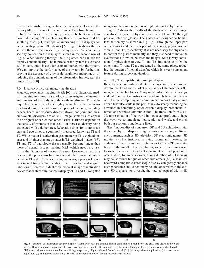
Information security display systems can be built using tem-poral interlacing S3D displays together with synchronized LCshutter glasses [21] and spatial interlacing S3D displays to-gether with polarized 3D glasses [22]. Figure 6 shows the re-sults of the information security display system. We can barelysee any content on the display as shown in the second row ofFig. 6. When viewing through the 3D glasses, we can see thedisplay content clearly. The interface of the system is clear andself-evident, and it is easy for users to interact with the system.We can improve the performance of the system by further im-proving the accuracy of gray scale-brightness mapping, or byreducing the dynamic range of the information frames, e.g., therange of [0, 200].
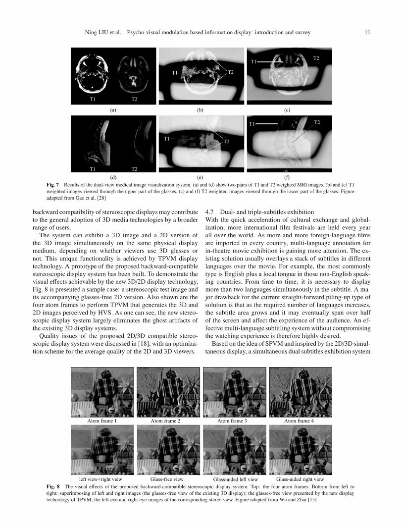
4.5 Dual-view medical image visualizationMagnetic resonance imaging (MRI) [66] is a diagnostic med-ical imaging tool used in radiology to investigate the anatomyand function of the body in both health and disease. This tech-nique has been proven to be highly valuable for the diagnosisof a broad range of conditions in all parts of the body, includingcancer, heart, and vascular disease, stroke, and joint and mus-culoskeletal disorders. On an MRI image, some tissues appearto be brighter or darker than other tissues. Darkness depends onthe density of protons in that area – an increased density beingassociated with a darker area. Relaxation times for protons canvary and two times are commonly measured, known as T1 andT2. White matter is darker than grey matter in T1-weighted im-ages and brighter than grey matter in T2- weighted images [67].T1 and T2 of pathologic tissues usually become longer thanthose of normal tissues, making MRI vwhich needs ery use-ful in the diagnosis of various diseases. However, in existingpractice, the physicians have to alternate their visual attentionbetween T1 and T2 images during diagnosis, a process knownas a mental transfer that needs a time of practice and is quitelaborious. Therefore, a dual-view medical image visualizationdevice that enables simultaneous display of T1 and T2 weighted
images on the same screen, is of high interest to physicians.Figure 7 shows the results of the dual-view medical image
visualization system. Physicians can view T1 and T2 throughpassive polarized glasses. The glasses are designed to be halflens half empty as shown in Fig. 7(b). Through the upper partof the glasses and the lower part of the glasses, physicians canview T1 and T2, respectively. It is not necessary for physiciansto control the glasses manually and they just need to move theeye fixations to switch between the images. So it is very conve-nient for physicians to view T1 and T2 simultaneously. On theother hand, T1 and T2 are presented at the same place, reduc-ing the burden of mental transfer, which is a very convenientfeature during surgery navigation.
4.6 2D/3D compatible stereoscopic displayRecent years have witnessed intensified research, rapid productdevelopment and wide market acceptance of stereoscopic (3D)image/video technologies. Many in the information technologyand entertainment industries and academia believe that the eraof 3D visual computing and communication has finally arrivedafter a few false starts in the past, thanks to steady technologicaladvances in computing, optoelectronic display, broadband In-ternet, and wireless communication. The transition from 2D to3D representation of the world in media can profoundly shapethe ways we communicate, learn, play and work, and enrichboth our economic and leisure lives.
The functionality of concurrent 3D and 2D exhibitions withthe same physical display is highly desirable in many multiuserenvironments, such as 3D television, 3D electronic games, 3Dmovies, etc. For instance, in living rooms and theaters, theaudience often split in their preferences to 3D or 2D presenta-tions; in the middle of an exhibition, some of them may wantto switch between 3D and 2D viewing at will independent ofothers. Also, for some viewers, a long duration of 3D viewingmay cause visual fatigue or other side effects [68], a seamlessbackward-compatible stereoscopic display can greatly enhanceuser experience and lessen many health concerns with the cur-rent 3D displays. As a result, the new concept of 3D to 2D
Fig. 6 Snapshot of information security display system. First row, the original information frames. Second row, the glass-free views of the blankscreen. Third row, direct comparison of glass/glass-free views. First to fifth columns gives the results for applications of image viewer, ebook reader,PDF reader, video player and random area hiding, respectively. Figure adapted from Gao et al. [21]. (a) Image viewer application; (b) ebook readerapplicaton; (c) PDF reader application; (d) video player application; (e) hiding random areas function
Ning LIU et al. Psycho-visual modulation based information display: introduction and survey 11
Fig. 7 Results of the dual-view medical image visualization system. (a) and (d) show two pairs of T1 and T2 weighted MRI images. (b) and (e) T1weighted images viewed through the upper part of the glasses. (c) and (f) T2 weighted images viewed through the lower part of the glasses. Figureadapted from Gao et al. [28]
backward compatibility of stereoscopic displays may contributeto the general adoption of 3D media technologies by a broaderrange of users.
The system can exhibit a 3D image and a 2D version ofthe 3D image simultaneously on the same physical displaymedium, depending on whether viewers use 3D glasses ornot. This unique functionality is achieved by TPVM displaytechnology. A prototype of the proposed backward-compatiblestereoscopic display system has been built. To demonstrate thevisual effects achievable by the new 3D/2D display technology,Fig. 8 is presented a sample case: a stereoscopic test image andits accompanying glasses-free 2D version. Also shown are thefour atom frames to perform TPVM that generates the 3D and2D images perceived by HVS. As one can see, the new stereo-scopic display system largely eliminates the ghost artifacts ofthe existing 3D display systems.
Quality issues of the proposed 2D/3D compatible stereo-scopic display system were discussed in [18], with an optimiza-tion scheme for the average quality of the 2D and 3D viewers.
4.7 Dual- and triple-subtitles exhibitionWith the quick acceleration of cultural exchange and global-ization, more international film festivals are held every yearall over the world. As more and more foreign-language filmsare imported in every country, multi-language annotation forin-theatre movie exhibition is gaining more attention. The ex-isting solution usually overlays a stack of subtitles in differentlanguages over the movie. For example, the most commonlytype is English plus a local tongue in those non-English speak-ing countries. From time to time, it is necessary to displaymore than two languages simultaneously in the subtitle. A ma-jor drawback for the current straight-forward piling-up type ofsolution is that as the required number of languages increases,the subtitle area grows and it may eventually span over halfof the screen and affect the experience of the audience. An ef-fective multi-language subtitling system without compromisingthe watching experience is therefore highly desired.
Based on the idea of SPVM and inspired by the 2D/3D simul-taneous display, a simultaneous dual subtitles exhibition system
Fig. 8 The visual effects of the proposed backward-compatible stereoscopic display system. Top: the four atom frames. Bottom from left toright: superimposing of left and right images (the glasses-free view of the existing 3D display); the glasses-free view presented by the new displaytechnology of TPVM; the left-eye and right-eye images of the corresponding stereo view. Figure adapted from Wu and Zhai [15]

12 Front. Comput. Sci., 2021, 15(3): 153703
was designed. The system was based on the commonly seen po-larization type 3D cinema system in which 2 projectors are usedto broadcast the images for left and right eye simultaneouslyusing a pair of polarizers. In this system, the display signal foreach projector was preprocessed to ensure that majority of theaudiences, can see subtitle in a default language with nakedeyes while another group of audiences with polarizer glassescan watch the movie with subtitles in the other language.
Moreover, a simultaneous triple-subtitle exhibition systemwas designed with a glasses-free no-subtitle view. Two 120 Hzprojectors with synchronized LC shutter glasses together withlinear polarization filters are used in the system. Audiences canenjoy the movie with 3 optional subtitles by choosing appro-priate LC glasses while the glasses-free audience can watch themovie without being bothered with the subtitles.
Figure 9 shows the results of four different views, present-ing an English-Chinese-Korean simultaneous subtitling system.The three subtitles can be seen through three pairs of differ-ent glasses. Fig. 9(b-d) are dark because they were capturedthrough the glasses. The glasses-free view that shows the originview in Fig. 9(a) is still of high quality.
5 Applications of data transmission on displayAs already discussed and reviewed in Section 4, the largeredundancies of modern display devices against human eyesmake it possible to serve multiple viewers with a single displaydevice [1, 14]. On the other hand, it is realized that instead ofserving multi-view for different users, the extra capacity of thedisplay can be used to transmit information to digital cameraswithout affecting normal viewing for the user. The interplay be-tween the display device and digital camera can be consideredas a unidirectional visible light communication (from displaysto digital cameras) [40].
To achieve data transmission between digital displays andcameras without affecting normal viewing, we need to exploitthe different image formation mechanisms between humaneyes and imaging sensors. For digital cameras, CCD (charge-coupled device) and CMOS (complementary metal oxide semi-conductor) [69] are two commonly used sensors. The highestframe rate f of the digital cameras is determined by the frame
Fig. 9 The triple subtitles exhibition system. (a) Shared view without subtitle;(b) shuttle glass 1 with English subtitle; (c) shuttle glass 2 with Chinese subtitle;(d) shuttle glass 3 with Korean subtitle. Figure adapted from Hu et al. [26]
acquisition time ta and frame read time tr as f = 1/(ta + tr).However, the integration period of the sensors, i.e., the expo-sure time is only a portion of the total imaging time (ta + tr).Therefore, the digital cameras cannot capture the informationdisplayed on the screen during the “blackout” period [30]. Onthe other hand, the electrochemical imaging processing of hu-man retina integrates charge induced by coming photons atall times without any “blackout”. Here we ignore the durationwhen the eye blinks. In other words, the imaging process of hu-man eyes and camera sensors can be modeled as continuous vs.discrete samplings.
As analyzed above, human eyes and imaging sensors applydifferent temporal convolution kernels to light sources duringimaging. To explore this difference, we can design optical sig-nals for displays in a way that humans and imaging sensors per-ceive drastically different images. For example, we can embeda QR code in an image so that human eyes only see the originalimage but the image taken by a camera contains the codes, asshown in Fig. 10.
5.1 Algorithms for data transmission using invisible QR codeThe QR (quick response) code is a two-dimensional (2D) ma-trix code that belongs to barcodes [70]. Since introduced in1994 by Denso Wave, the QR code has gained wide accep-tance in such diverse industries as manufacturing, warehousingand logistics, retailing, healthcare, life sciences, transportationand office automation. Now with the explosive growth of smart-phones, the QR code is also being used in mobile marketingand advertising campaigns as a fast and effective way of con-necting with customers and providing end-user content, includ-ing Web links, mobile coupons, airline boarding passes, etc.QR codes serve as a convenient unidirectional communicationchannel from printed materials or display panels to a mobilecomputing device equipped with a camera.
Figure 11 shows the communication model of data transmis-sion based on TPVM using QR code as an example. First, let fdbe the flicker fusion frequency and fc = K fd be the refresh rateof a digital display. The embedder, taking an image i ∈ RN and
Fig. 10 Image formation via TPVM for imaging sensors and human visualsystems. The display emits a pair of negative and positive QR code embeddedimages alternately. Human eyes can just see the original image but imaging sen-sors get the image containing the QR code that can be extracted by algorithms.Figure adapted from Gao et al. [33]

Ning LIU et al. Psycho-visual modulation based information display: introduction and survey 13
Fig. 11 Communication model of TPVM based data transmission. Figure adapted from Gao et al. [33]
a pattern c ∈ RN as input (N is the resolution of i and c is paddedwith zeros to have the same size with i), generates a set of basisimages x1, x2, . . . , xK which are subjected to
∑Kj=1 x j = i. The
high-speed display emits the basis images sequentially. Humanvisual systems integrate all of the light fields of the basis im-ages to form the complete image i. But for the imaging sensor,because of the “blackout” period, the camera cannot receive allthe optical signals emitted from the screen. That is, the basisimages are weighted to form the image y = Xw, where y ∈ RN ,w ∈ RK and X ∈ RN×K contains all x j’s as its columns. Thechannel from the display to the pattern reader is noisy, becausethat the relative position and angle between camera and screenare not fixed. Also, the luminance change impacts the imagequality. All these changes can be represented by a noise termn. Under the influence of n, the weighted image y turns into y′.For a specific pattern reader, we want to design an embedderthat minimizes the visual distance between c and y′, and yet ccan be successfully extracted and decoded with high probabil-ity.
The principle of the embedder is to minimize the visual dis-tance between the pattern c and the image y′, which is equiva-lent to minimize the visual distance between c and the weightedimage y, as shown in Fig. 11. Here we just need to consider thesquare area of the pattern. For an 120 Hz LCD display, K = 2.So we need to design two basis images x1 and x2 which are sub-jected to x1+x2 = i. Based on the TPVM technology, x1 and x2
are emitted from the display alternately. Support w = [1, 0]T,then y = x1 × 1 + x2 × 0 = x1. Now, we just need to design x1
that has the minimum visual distance to the pattern c. That is,we just need to design x1 such that it has the same structure asc, as outlined in Algorithm 1.
According to the communication model in Fig. 11, in the de-sign of the system, we have two objectives: 1) QR codes shouldbe visually invisible to human eyes, 2) QR codes should be de-tectable by smartphones easily. For the first objective, the hu-man visual system integrates all light field of the basis imagesto form the target image i =
∑Kj=1 x j, which can be formulated
as
min0�X�1
12‖i − X1‖2F , (57)
where ‖ · ‖F is the Frobenius norm used to measure the distancebetween the target image and reconstructed one. The constraint0 � X � 1 is because the grayscale value of an image pixel has
Algorithm 1 Algorithms for pattern embedding
Require i, c ∈ RN , K = 21: x1 = i;2: x1( f ind(c == 0)) = 0;3: x2 = i − x1;
lower and upper bounds e.g., [0, 255] for 8-bit depth. In the fol-lowing analysis, we normalize the range to [0, 1] for simplicity.
1 stands for a column vector of all 1s. For the second objective,we need to minimize the visual distance between the QR codec and the image y′, which is equivalent to minimize the visualdistance between c and the weighted image y. Then the costfunction is expressed as
min0�X�1
12‖c − Xw‖2F , (58)
where w is determined by the camera. Combining these twoobjectives, the cost function is reformulated as
min0�X�1
12‖i − X1‖2F +
λ
2‖c − Xw‖2F , (59)
where λ is a nonnegative regularization coefficient controllingthe tradeoff of image qualities between i and c. Eq. (59) can besimplified as
min0�X�1
12‖Y − XW‖2F , (60)
where Y = [i| √λc], W = [1| √λw]. Note that, the parametersof the camera (e.g., frame rate, shutter speed, exposure time)can be controlled in the computing stage, that is, the weightsw of camera can be determined freely. For simplicity, we letw = [1, 0, . . . , 0]T, indicating that the first basis image is set asthe QR code c.
The problem in Eq. (60) is a constrained nonnegative leastsquares (NNLS) problem. The gradients of the cost functionsDF (Y‖XW) in Eq. (60) can be expressed by
∂DF(Y‖XW)∂X
= XWWT − YWT. (61)
The sequential learning rules can be obtained by equating thegradients to zero and setting the negative elements to zero andthe elements larger than 1 to 1:
X = [YWT(WWT)−1][0,1]. (62)
Using TPVM display technology, as shown in Fig. 10, weachieve the two conflicting objectives of QR code completely:enhance visual appearance and maximize decoding robustness,as shown in Fig. 12.
Invisible QR codes were tested on the Kodak image dataset.There are 24 images with the resolution of 768 × 512 or512 × 768 in Kodak image sets. Figure 13 shows six results ofinvisible QR codes scanned by iPhone 5S. The reader returnsthe correct data string of “Life is beautiful.” stored in the QRcodes.
To improve the robustness of invisibility of QR code, [71]proposed a fast restoration-recognition method to scan invisi-ble QR codes by smartphones using deep convolutional neural

14 Front. Comput. Sci., 2021, 15(3): 153703
Fig. 12 Two applications of the proposed invisible QR codes. (a) The user views images without perceiving the invisible QR codes; (b) smart-phones detect and recolonize the invisible QR codes; (c) smartphones open the links stored in the invisible QR codes. In the first row, the user scansa dress (Elsa’s dress in the movie of Frozen 2013) on the screen and the smartphone detect the invisible QR code that links to an online store. In thesecond row, the user scans a person (Agnes Gru in the movie of Despicable Me 2010) about who he wants to get more information and the invisibleQR code links to the corresponding Wikipedia page
Fig. 13 The invisible QR codes scanned by iPhone 5S
networks. Extensive experiment results show that the proposedmethods effectively improve the indivisibility of QR code andcan efficiently recognize the invisible QR code correctly andstably.
Along this line of work, several aspects can be refined andimproved. First, in the future, the system can be developed onmultiple mobile platforms, e.g., IOS, Windows Phone, and An-droid, so that users with mobile devices can scan the invisibleQR codes on screens anytime and anywhere. Second, in the fu-ture, invisible QR code detection should be studied to make thedetection and recognition more reliable and at higher speeds.Third, based on the idea of the invisible QR code, many appli-cations can be implemented. For example, when watching TVor digital signages, people can get more information about thetargets interested in (e.g., a coat on a movie star) through theinvisible QR codes.
5.2 Anti-piracy display and piracy trackingMovie piracy has a profound impact on the motion picture in-dustry. The Motion Picture Association of America (MPAA)[72] conducted an investigation into movie piracy in 2005. Ac-cording to the statistics in the report, the major U.S. motion
picture studios lost 6.1 billion USD or more annually. Theselosses in revenue will cause serious financial problems for thestudios and even contribute to their current downfall. In 2010,for example, over one million copies of James Cameron Avatarwas downloaded illegally in just seven days [73]. Given the law,movie piracy is considered a crime all over the world. As an im-portant source of movie piracy, camcorder piracy accounts forabout 23% of the piracy methods according to BBC News [74].As the source of infringing DVDs, camcorder movies spreadrapidly on the internet.
As a deterrent against camcorder piracy, several watermark-ing technologies have been proposed [75–79]. The main ideaof these techniques is to embed an imperceptible message (i.e.,tracking information) into the movie. The message indicates thetheater to which it was distributed, the equipment on which itwas shown, the date and time of showing, and perhaps infor-mation identifying the projectionist. If movies are pirated andthe illegal recordings are transmitted via the Internet or someother route, then the message can be extracted from the piratedmovies to reveal the person or organization responsible for theunauthorized release. As a forensic tool, tracking informationgives the content owner information to help manage the piracy
Ning LIU et al. Psycho-visual modulation based information display: introduction and survey 15
problem and serves as further surveillance and a deterrent to fu-ture piracy. However, there are two problems with watermark-ing techniques. First, they cannot obstruct or defeat camcorderpiracy directly because the watermarks in the pirated moviesare invisible and not objectionable enough. Second, althoughby strict definition, the alteration of watermarking must be im-perceptible, both visually and audibly. Potential perceptual ar-tifacts are still left by the watermark embedding process, thevideo content viewed in the theatre may be affected.
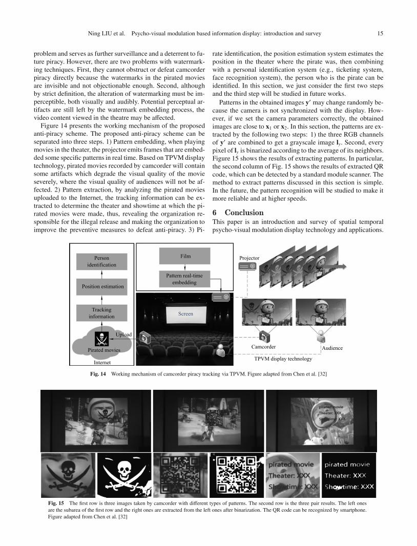
Figure 14 presents the working mechanism of the proposedanti-piracy scheme. The proposed anti-piracy scheme can beseparated into three steps. 1) Pattern embedding, when playingmovies in the theater, the projector emits frames that are embed-ded some specific patterns in real time. Based on TPVM displaytechnology, pirated movies recorded by camcorder will containsome artifacts which degrade the visual quality of the movieseverely, where the visual quality of audiences will not be af-fected. 2) Pattern extraction, by analyzing the pirated moviesuploaded to the Internet, the tracking information can be ex-tracted to determine the theater and showtime at which the pi-rated movies were made, thus, revealing the organization re-sponsible for the illegal release and making the organization toimprove the preventive measures to defeat anti-piracy. 3) Pi-
rate identification, the position estimation system estimates theposition in the theater where the pirate was, then combiningwith a personal identification system (e.g., ticketing system,face recognition system), the person who is the pirate can beidentified. In this section, we just consider the first two stepsand the third step will be studied in future works.
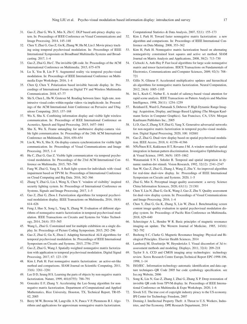
Patterns in the obtained images y′ may change randomly be-cause the camera is not synchronized with the display. How-ever, if we set the camera parameters correctly, the obtainedimages are close to x1 or x2. In this section, the patterns are ex-tracted by the following two steps: 1) the three RGB channelsof y′ are combined to get a grayscale image ly. Second, everypixel of ly is binarized according to the average of its neighbors.Figure 15 shows the results of extracting patterns. In particular,the second column of Fig. 15 shows the results of extracted QRcode, which can be detected by a standard module scanner. Themethod to extract patterns discussed in this section is simple.In the future, the pattern recognition will be studied to make itmore reliable and at higher speeds.
6 ConclusionThis paper is an introduction and survey of spatial temporalpsycho-visual modulation display technology and applications.
Fig. 14 Working mechanism of camcorder piracy tracking via TPVM. Figure adapted from Chen et al. [32]
Fig. 15 The first row is three images taken by camcorder with different types of patterns. The second row is the three pair results. The left onesare the subarea of the first row and the right ones are extracted from the left ones after binarization. The QR code can be recognized by smartphone.Figure adapted from Chen et al. [32]

16 Front. Comput. Sci., 2021, 15(3): 153703
The TPVM or SPVM or STPVM technology was proposed toexploit the redundancies of modern display devices in terms ofhigh spatial and temporal resolutions as against to discrimina-tion power of human eye. The TPVM or SPVM or STPVMtechnology can generate multiple visual percepts for differentviewers or to transmit non-visual data to computing deviceswithout affecting normal viewing. Basic concepts and solutionsof TPVM or SPVM or STPVM was introduced, and variousapplications in dual-view display, multiple user display, mul-tiple subtitle exhibition, security display, visible communica-tions, etc. are also extensively surveyed.
Future directions of research on psycho-visual modulationare explored. In the applications of psycho-visual modulation,we found that the spatial and temporal resolutions of S3D displays are not higher enough. Some artifacts are perceivable inthe shared view, especially on the edges of the personal viewswhere the spatial frequency is very high. For temporal resolu-tion, humans perceive visual flicker artifacts at rates over 500Hz when a display includes high-frequency spatial edges [80].The spatial and temporal resolution limits for human visual sys-tems need to be tested in the future.
Moreover, more applications based on psycho-visual mod-ulation can be implemented. For instance, multi-view displayscan be explored in high spatial and temporal resolution dis-plays. Visible light transmission via displays may also be use-ful in the future. We can combine temporal and spatial psycho-visual modulation to achieve more views on a single display.
Acknowledgements The authors would like thanks the National NaturalScience Foundation of China (NSFC) for the support (Grant Nos. 61901259,61831015, 61771305, 61927809, and U1908210) and China Postdoctoral Sci-ence Foundation (BX2019208).
References
1. Wu X, Zhai G. Temporal psychovisual modulation: a new paradigm of in-formation display [exploratory DSP]. IEEE Signal Processing Magazine,2013, 30(1): 136–141
2. Kelly D H. Spatio-temporal frequency characteristics of color-visionmechanisms. Journal of the Optical Society America, 1974, 64(7): 983–990
3. Varner D, Jameson D, Hurvich L M. Temporal sensitivities related tocolor theory. Journal of the Optical Society of America A, 1984, 1(5):474–481
4. Instruments T. DLP discovery 4100 development kit. See Ti Website,2015
5. Corporation N. NVIDIA 3D Vision. See Nvidia Website, 2014
6. Ko H, Paik J, Zalewski G. Stereoscopic screen sharing method and appa-ratus. 2010. US Patent App. 12/503,029
7. Corporation N. Pixel density display listing. See Pixensity Website, 2018
8. Karnik A, Martinez Plasencia D, Mayol-Cuevas W, Subramanian S.PiVOT: personalized view-overlays for tabletops. In: Proceedings of the25th Annual ACM Symposium on User Interface Software and Technol-ogy. 2012, 271–280
9. Wetzstein G, Lanman D, Hirsch M, Raskar R. Tensor displays: compres-sive light field synthesis using multilayer displays with directional back-lighting. ACM Transactions on Graphics, 2012, 31(4): 80
10. Ye G, State A, Fuchs H. A practical multi-viewer tabletop autostereo-scopic display. In: Proceedings of IEEE International Symposium onMixed and Augmented Reality. 2010, 147–156
11. Karnik A, Mayol-Cuevas W, Subramanian S. MUSTARD: a multi user
see through AR display. In: Proceedings of the SIGCHI Conference onHuman Factors in Computing Systems. 2012, 2541–2550
12. Nashel A, Fuchs H. Random hole display: a non-uniform barrier au-tostereoscopic display. In: Proceedings of 3DTV Conference: The TrueVision — Capture, Transmission and Display of 3D Video. 2009, 1–4
13. Lanman D, Wetzstein G, Hirsch M, Heidrich W, Raskar R. Polarizationfields: dynamic light field display using multi-layer LCDs. In: Proceed-ings of the SIGGRAPH Asia Conference. 2011, 1–10
14. Zhai G, Wu X. Multiuser collaborative viewport via temporal psychovi-sual modulation [applications corner]. IEEE Signal Processing Magazine,2014, 31(5): 144–149
15. Wu X, Zhai G. Backward compatible stereoscopic displays via temporalpsychovisual modulation. In: Proceedings of SIGGRAPH Asia EmergingTechnologies. 2012
16. Jiao L, Shu X, Wu X. LED backlight adjustment for backward-compatiblestereoscopic display. IEEE Signal Processing Letters, 2013, 20(12):1203–1206
17. Ma R, Au O C, Wan P, Xu L, Sun W, Hu W. Improved temporal psy-chovisual modulation for backward-compatible stereoscopic display. In:Proceedings of IEEE Global Conference on Signal and Information Pro-cessing. 2014, 1034–1038
18. Chen Y, Zhai G, Zhou J, Wan Z, Tang L. Global quality of assessment andoptimization for the backward-compatible stereoscopic display system.In: Proceedings of IEEE International Conference on Image Processing.2017, 191–195
19. Fujimura W, Koide Y, Songer R, Hayakawa T, Shirai A, Yanaka K. 2x3D:real time shader for simultaneous 2D/3D hybrid theater. In: Proceedingsof SIGGRAPH Asia Emerging Technologies. 2012, 1–2
20. Scher S, Liu J, Vaish R, Gunawardane P, Davis J. 3D+2DTV: 3D dis-plays with no ghosting for viewers without glasses. ACM Transactionson Graphics, 2013, 32(3): 21
21. Gao Z, Zhai G, Min X. Information security display system based ontemporal psychovisual modulation. In: Proceedings of IEEE InternationalSymposium on Circuits and Systems. 2014, 449–452
22. Hu C, Zhai G, Gao Z, Min X. Information security display system basedon spatial psychovisual modulation. In: Proceedings of IEEE Interna-tional Conference on Multimedia and Expo. 2014, 1–4
23. Chen Y, Liu N, Zhai G, Gao Z, Gu K. Information security display systemon android device. In: Proceedings of IEEE Region 10 Conference. 2016,1634–1637
24. Li X, Zhai G, Wang J, Gu K. Portable information security display sys-tem via spatial psychovisual modulation. In: Proceedings of IEEE VisualCommunications and Image Processing. 2017, 1–4
25. Hu C, Zhai G, Gao Z, Min X. Simultaneous dual-subtitles exhibition viaspatial psychovisual modulation. In: Proceedings of IEEE InternationalSymposium on Broadband Multimedia Systems and Broadcasting. 2014,1–4
26. Hu C, Zhai G, Gao Z, Min X. Simultaneous triple subtitles exhibitionvia temporal psychovisual modulation. In: Proceedings of the 9th IEEEConference on Industrial Electronics and Applications. 2014, 944–947
27. Sun W, Zhai G, Gao Z, Chen T, Zhu Y, Wang Z. Dual-view oracle bonescript recognition system via temporal-spatial psychovisual modulation.In: Proceedings of IEEE Conference on Multimedia Information Process-ing and Retrieval. 2020, 193–198
28. Gao Z, Zhai G, Hu C, Min X. Dual-view medical image visualizationbased on spatial-temporal psychovisual modulation. In: Proceedings ofIEEE International Conference on Image Processing. 2014
29. Fang W, Zhai G, Yang X, Liu J, Chen Y. An eye-friendly dual-view pro-jection system using temporal psychovisual modulation. In: Proceedingsof IEEE International Symposium on Broadband Multimedia Systemsand Broadcasting. 2017, 1–5
30. Zhai G, Wu X. Defeating camcorder piracy by temporal psychovisualmodulation. Journal of Display Technology, 2014, 10(9): 754–757
Ning LIU et al. Psycho-visual modulation based information display: introduction and survey 17
31. Gao Z, Zhai G, Wu X, Min X, Zhi C. DLP based anti-piracy display sys-tem. In: Proceedings of IEEE Conference on Visual Communications andImage Processing. 2014, 145–148
32. Chen Y, Zhai G, Gao Z, Gu K, Zhang W, Hu M, Liu J. Movie piracy track-ing using temporal psychovisual modulation. In: Proceedings of IEEEInternational Symposium on Broadband Multimedia Systems and Broad-casting. 2017, 1–4
33. Gao Z, Zhai G, Hu C. The invisible QR code. In: Proceedings of the ACMInternational Conference on Multimedia. 2015, 675–678
34. Lu X, You B, Lin P Y. Augmented reality via temporal psycho-visualmodulation. In: Proceedings of IEEE International Conference on Multi-media Expo Workshops. 2016, 1–4
35. Chen Q, Chen Y. Polarization based invisible barcode display. In: Pro-ceedings of International Forum on Digital TV and Wireless MultimediaCommunication. 2018, 67–77
36. Shi S, Chen L, Hu W, Gruteser M. Reading between lines: high-rate, non-intrusive visual codes within regular videos via implicitcode. In: Proceed-ings of the ACM International Joint Conference on Pervasive and Ubiq-uitous Computing. 2015, 157–168
37. Wu X, Shu X. Combining information display and visible light wirelesscommunication. In: Proceedings of IEEE International Conference onAcoustics, Speech and Signal Processing. 2015, 1657–1661
38. Shu X, Wu X. Frame untangling for unobtrusive display-camera visi-ble light communication. In: Proceedings of the 24th ACM InternationalConference on Multimedia. 2016, 650–654
39. Liu K, Wu X, Shu X. On display-camera synchronization for visible lightcommunication. In: Proceedings of Visual Communications and ImageProcessing. 2015, 1–4
40. Hu C, Zhai G, Gao Z. Visible light communication via temporal psycho-visual modulation. In: Proceedings of the 23rd ACM International Con-ference on Multimedia. 2015, 785–788
41. Fang W, Zhai G, Yang X. A flash light system for individuals with visualimpairment based on TPVM. In: Proceedings of International Conferenceon Cloud Computing and Big Data. 2016, 362–366
42. Zhang Y, Zhai G, Liu J, Weng X, Chen Y. ‘window of visibility’ inspiredsecurity lighting system. In: Proceedings of International Conference onSystems, Signals and Image Processing. 2017, 1–5
43. Gao Z, Zhai G, Zhou J. Factorization algorithms for temporal psychovi-sual modulation display. IEEE Transactions on Multimedia, 2016, 18(4):614–626
44. Feng J, Huo X, Song L, Yang X, Zhang W. Evaluation of different algo-rithms of nonnegative matrix factorization in temporal psychovisual mod-ulation. IEEE Transactions on Circuits and Systems for Video Technol-ogy, 2014, 24(4): 553–565
45. Wang L, Zhai G. Constrained nmf for multiple exhibition on a single dis-play. In: Proceedings of Picture Coding Symposium. 2015, 292–296
46. Gao Z, Zhai G, Gu X, Zhou J. Adapting hierarchical ALS algorithms fortemporal psychovisual modulation. In: Proceedings of IEEE InternationalSymposium on Circuits and Systems. 2015, 2756–2759
47. Gao Z, Zhai G, Wang J. Spatially-weighted nonnegative matrix factoriza-tion with application to temporal psychovisual modulation. Digital SignalProcessing, 2017, 67: 123–130
48. Kim J, Park H. Fast nonnegative matrix factorization: an active-set-likemethod and comparisons. SIAM Journal on Scientific Computing, 2011,33(6): 3261–3281
49. Lee D D, Seung H S. Learning the parts of objects by non-negative matrixfactorization. Nature, 1999, 401(6755): 788–791
50. Gonzalez E F, Zhang Y. Accelerating the Lee-Seung algorithm for non-negative matrix factorization. Department of Computational and AppliedMathematics, Rice University, Houston, TX, Technical Report, TR-05-02, 2005
51. Berry M W, Browne M, Langville A N, Pauca V P, Plemmons R J. Algo-rithms and applications for approximate nonnegative matrix factorization.
Computational Statistics & Data Analysis, 2007, 52(1): 155–17352. Kim J, Park H. Toward faster nonnegative matrix factorization: a new
algorithm and comparisons. In: Proceedings of IEEE International Con-ference on Data Mining. 2008, 353–362
53. Kim H, Park H. Nonnegative matrix factorization based on alternatingnonnegativity constrained least squares and active set method. SIAMJournal on Matrix Analysis and Applications, 2008, 30(2): 713–730
54. Cichocki A, Anh-Huy P. Fast local algorithms for large scale nonnegativematrix and tensor factorizations. IEICE Transactions on Fundamentals ofElectronics, Communications and Computer Sciences, 2009, 92(3): 708–721
55. Gillis N, Glineur F. Accelerated multiplicative updates and hierarchicalals algorithms for nonnegative matrix factorization. Neural Computation,2012, 24(4): 1085–1105
56. Itti L, Koch C, Niebur E. A model of saliency-based visual attention forrapid scene analysis. IEEE Transactions on Pattern Analysis and MachineIntelligence, 1998, 20(11): 1254–1259
57. Reinhard E, Ward G, Pattanaik S, Debevec P. High Dynamic Range Imag-ing: Acquisition, Display, and Image-Based Lighting (The Morgan Kauf-mann Series in Computer Graphics). San Francisco, CA, USA: MorganKaufmann Publishers Inc., 2005
58. Li D, Gao Z, Zhang X P, Zhai G, Yang X. Generative adversarial networksfor non-negative matrix factorization in temporal psycho-visual modula-tion. Digital Signal Processing, 2020, 100: 102681
59. Gao Z, Zhai G. Dual-view display based on spatial psychovisual modula-tion. IEEE Access, 2018, 6: 41356–41366
60. NÑsÑnen R E, Kukkonen H T, Rovamo J M. A window model for spatialintegration in human pattern discrimination. Investigative Ophthalmology& Visual Science, 1995, 36(9): 1855–1862
61. Watamaniuk S N J, Sekuler R. Temporal and spatial integration in dy-namic random-dot stimuli. Vision Research, 1992, 32(12): 2341–2347
62. Sun W, Gao Z, Zhai G, Zhang J, Wang Z, Zhu Y. An improved algorithmfor real-time dual-view display. In: Proceedings of IEEE InternationalSymposium on Circuits and Systems. 2020, 1–5
63. Zhai G, Min X. Perceptual image quality assessment: a survey. ScienceChina Information Sciences, 2020, 63(11): 211301
64. Chen Y, Liu N, Zhai G, Gu K, Wang J, Gao Z, Zhu Y. Quality assessmentfor dual-view display system. In: Proceedings of Visual Communicationsand Image Processing. 2016, 1–4
65. Chen Y, Zhai G, Gu K, Zhang X, Lin W, Zhou J. Benchmarking screencontent image quality evaluation in spatial psychovisual modulation dis-play system. In: Proceedings of Pacific Rim Conference on Multimedia.2018, 629–640
66. Scherzinger A L, Hendee W R. Basic principles of magnetic resonanceimaging–an update. The Western Journal of Medicine, 1985, 143(6):782–792
67. Bushong S C, Clarke G. Magnetic Resonance Imaging: Physical and Bi-ological Principles. Elsevier Health Sciences, 2014
68. Lambooij M, IJsselsteijn W, Heynderickx I. Visual discomfort of 3d tv:assessment methods and modeling. Displays, 2011, 32(4): 209–218
69. Taylor S A. CCD and CMOS imaging array technologies: technologyreview. Xerox Research Centre Europe,Technical Report EPC-1998-106,1998, 1–14
70. ISO/IEC . Information technology–automatic identification and data cap-ture techniques–QR Code 2005 bar code symbology specification. seeIso.org Website, 2006
71. Song K, Liu N, Gao Z, Zhang J, Zhai G, Zhang X P. Deep restoration ofinvisible QR code from TPVM display. In: Proceedings of IEEE Interna-tional Conference on Multimedia & Expo Workshops. 2020, 1–6
72. Siwek S E. The true cost of copyright industry piracy to the US economy.IPI Center for Technology Freedom, 2007
73. Dorning J. Intellectual Property Theft: A Threat to U.S. Workers, Indus-tries, and Our Economy. DPE Research Department, 2014
18 Front. Comput. Sci., 2021, 15(3): 153703
74. NEWS B. The fact and fiction of camcorder piracy. see Bbc.co.uk Web-site, 2015
75. Byers S, Cranor L F, Cronin E, Korman D, McDaniel P. An analysis ofsecurity vulnerabilities in the movie production and distribution process.Telecommunications Policy, 2004, 28(78): 619–644
76. Haitsma J, Kalker T. A watermarking scheme for digital cinema. In: Pro-ceedings of International Conference on Image Processing. 2001, 487–489
77. Nguyen P, Balter R, Montfort N, Baudry S. Registration methods for non-blind watermark detection in digital cinema applications. In: Proceedingsof Security and Watermarking of Multimedia Contents V. 2003, 553–562
78. Lubin J, Bloom J A, Cheng H. Robust content-dependent high-fidelitywatermark for tracking in digital cinema. In: Proceedings of Security andWatermarking of Multimedia Contents V. 2003, 536–545
79. Nakashima Y, Tachibana R, Babaguchi N. Watermarked movie sound-track finds the position of the camcorder in a theater. IEEE Transactionson Multimedia, 2009, 11(3): 443–454
80. Davis J, Hsieh Y H, Lee H C. Humans perceive flicker artifacts at 500 hz.Scientific Reports, 2015, 5: 7861
Ning Liu received the PhD degree from ShanghaiJiao Tong University, China in 2010. He is cur-rently an assistant professor with Shanghai JiaoTong University, China. His research interests in-clude wireless and mobile communication sys-tems, net-work media information security, intel-ligent hard-ware, and mobile Internet.
Zhongpai Gao received the BSc degree in elec-tronic and information engineering from theHuazhong University of Science and Technology,China in 2013 and the PhD degree from Shang-hai Jiao Tong University, China in 2018. He was avisiting PhD Student with the Schepens Eye Re-search Institute, Harvard Medical School, USA,from 2016 to 2018. Currently, he is a postdoctoral
fellow in Shanghai Jiao Tong University, China. His research interestsinclude stereoscopic 3D and 3D computer vision.
Jia Wang received the BSc degree in electronic en-gineering, the MS degree in pattern recognitionand intelligence control, and the PhD degree inelectronic engineering from Shanghai Jiao TongUniversity, China in 1997, 1999, and 2002, respec-tively. He is currently a professor with the De-partment of Electronic Engineering, Shanghai JiaoTong University, and also a member of the Shang-
hai Key Laboratory of Digital Media Processing and Transmission. Hisresearch interests include multiuser information theory and mathemat-ics for artificial intelligence.
Guangtao Zhai (Senior Member, IEEE) receivedthe BE and ME degrees from Shandong Univer-sity, China in 2001 and 2004, respectively, andthe PhD degree from Shanghai Jiao Tong Univer-sity, China in 2009. From 2008 to 2009, he was aVisiting Student with the Department of Electricaland Computer Engineering, McMaster University,Canada, where he was a post-doctoral fellow from
2010 to 2012. From 2012 to 2013, he was a Humboldt Research Fel-low with the Institute of Multimedia Communication and Signal Pro-cessing, Friedrich Alexander University of Erlangen-Nuremberg, Ger-many. He is currently a Research Professor with the Institute of Im-age Communication and Information Processing, Shanghai Jiao TongUniversity. His research interests include multimedia signal process-ing and perceptual signal processing. He received the Award of Na-tional Excellent PhD Thesis from the Ministry of Education of Chinain 2012.