PSS 6-1A4 A - dp-flow · · 2016-02-08PSS 6-1A4 A Model 876PH Intelligent Transmitter for pH, ......
20
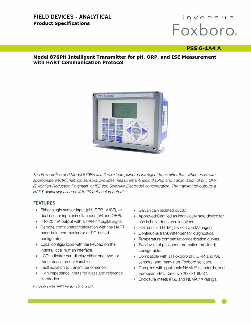
FIELD DEVICES - ANALYTICAL Product Specifications Logo PSS 6-1A4 A Model 876PH Intelligent Transmitter for pH, ORP, and ISE Measurement with HART Communication Protocol The Foxboro ® brand Model 876PH is a 2-wire loop powered intelligent transmitter that, when used with appropriate electrochemical sensors, provides measurement, local display, and transmission of pH, ORP (Oxidation-Reduction Potential), or ISE (Ion Selective Electrode) concentration. The transmitter outputs a HART digital signal and a 4 to 20 mA analog output. FEATURES Either single sensor input (pH, ORP, or ISE), or dual sensor input (simultaneous pH and ORP). 4 to 20 mA output with a HART (1) digital signal. Remote configuration/calibration with the HART hand-held communicator or PC-based configurator. Local configuration with the keypad on the integral local human interface. LCD indicator can display either one, two, or three measurement variables. Fault isolation to transmitter or sensor. High impedance inputs for glass and reference electrodes. Galvanically isolated output. Approved/Certified as intrinsically safe device for use in hazardous area locations. FDT certified DTM (Device Type Manager). Continuous transmitter/sensor diagnostics. Temperature compensation/calibration curves. Two levels of passcode protection provided; configurable. Compatible with all Foxboro pH, ORP, and ISE sensors, and many non-Foxboro sensors. Complies with applicable NAMUR standards, and European EMC Directive 2004/108/EC. Enclosure meets IP66 and NEMA 4X ratings. (1) Usable with HART Versions 5, 6, and 7.
Transcript of PSS 6-1A4 A - dp-flow · · 2016-02-08PSS 6-1A4 A Model 876PH Intelligent Transmitter for pH, ......
FIELD DEVICES - ANALYTICALProduct Specifications Logo
PSS 6-1A4 A
Model 876PH Intelligent Transmitter for pH, ORP, and ISE Measurementwith HART Communication Protocol
®
The Foxboro brand Model 876PH is a 2-wire loop powered intelligent transmitter that, when used with appropriate electrochemical sensors, provides measurement, local display, and transmission of pH, ORP (Oxidation-Reduction Potential), or ISE (Ion Selective Electrode) concentration. The transmitter outputs a HART digital signal and a 4 to 20 mA analog output.FEATURES
Either single sensor input (pH, ORP, or ISE), or dual sensor input (simultaneous pH and ORP).
4 to 20 mA output with a HART(1) digital signal. Remote configuration/calibration with the HART
hand-held communicator or PC-based configurator.
Local configuration with the keypad on the integral local human interface.
LCD indicator can display either one, two, or three measurement variables.
Fault isolation to transmitter or sensor. High impedance inputs for glass and reference
electrodes.
Galvanically isolated output. Approved/Certified as intrinsically safe device for
use in hazardous area locations. FDT certified DTM (Device Type Manager). Continuous transmitter/sensor diagnostics. Temperature compensation/calibration curves. Two levels of passcode protection provided;
configurable. Compatible with all Foxboro pH, ORP, and ISE
sensors, and many non-Foxboro sensors. Complies with applicable NAMUR standards, and
European EMC Directive 2004/108/EC. Enclosure meets IP66 and NEMA 4X ratings.
(1) Usable with HART Versions 5, 6, and 7.
PSS 6-1A4 APage 2
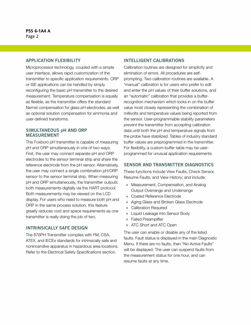
APPLICATION FLEXIBILITY
Microprocessor technology, coupled with a simple user interface, allows rapid customization of the transmitter to specific application requirements. ORP or ISE applications can be handled by simply reconfiguring the basic pH transmitter to the desired measurement. Temperature compensation is equally as flexible, as the transmitter offers the standard Nernst compensation for glass pH electrodes, as well as optional solution compensation for ammonia and user-defined transforms.
SIMULTANEOUS pH AND ORP MEASUREMENT
This Foxboro pH transmitter is capable of measuring pH and ORP simultaneously in one of two ways. First, the user may connect separate pH and ORP electrodes to the sensor terminal strip and share the reference electrode from the pH sensor. Alternatively, the user may connect a single combination pH/ORP sensor to the sensor terminal strip. When measuring pH and ORP simultaneously, the transmitter outputs both measurements digitally via the HART protocol. Both measurements may be viewed on the LCD display. For users who need to measure both pH and ORP in the same process solution, this feature greatly reduces cost and space requirements as one transmitter is really doing the job of two.
INTRINSICALLY SAFE DESIGN
The 876PH Transmitter complies with FM, CSA, ATEX, and IECEx standards for intrinsically safe and nonincendive apparatus in hazardous area locations. Refer to the Electrical Safety Specifications section.
INTELLIGENT CALIBRATIONS
Calibration routines are designed for simplicity and elimination of errors. All procedures are self-prompting. Two calibration routines are available. A “manual” calibration is for users who prefer to edit and enter the pH values of their buffer solutions, and an “automatic” calibration that provides a buffer-recognition mechanism which locks in on the buffer value most closely representing the combination of millivolts and temperature values being reported from the sensor. User-programmable stability parameters prevent the transmitter from accepting calibration data until both the pH and temperature signals from the probe have stabilized. Tables of industry standard buffer values are preprogrammed in the transmitter. For flexibility, a custom buffer table may be user-programmed for unusual application requirements.
SENSOR AND TRANSMITTER DIAGNOSTICS
These functions include View Faults, Check Sensor, Resume Faults, and View History; and include:
Measurement, Compensation, and Analog Output Overrange and Underrange
Coated Reference Electrode Aging Glass and Broken Glass Electrode Calibration Required Liquid Leakage into Sensor Body Failed Preamplifier ATC Short and ATC Open
The user can enable or disable any of the listed faults. Fault status is displayed in the main Diagnostic Menu. If there are no faults, then “No Active Faults” will be displayed. The user can suspend faults from the measurement status for one hour, and can resume faults at any time.
PSS 6-1A4 APage 3
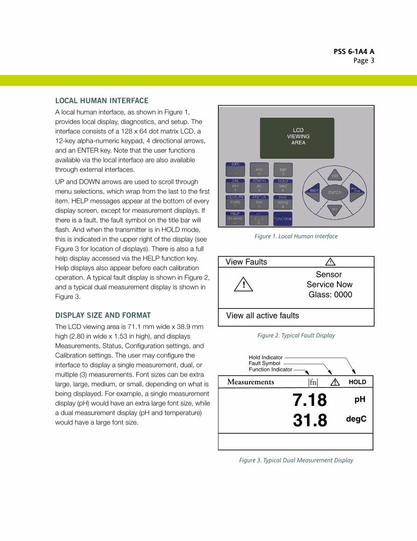
LOCAL HUMAN INTERFACE
A local human interface, as shown in Figure 1, provides local display, diagnostics, and setup. The interface consists of a 128 x 64 dot matrix LCD, a 12-key alpha-numeric keypad, 4 directional arrows, and an ENTER key. Note that the user functions available via the local interface are also available through external interfaces.
UP and DOWN arrows are used to scroll through menu selections, which wrap from the last to the first item. HELP messages appear at the bottom of every display screen, except for measurement displays. If there is a fault, the fault symbol on the title bar will flash. And when the transmitter is in HOLD mode, this is indicated in the upper right of the display (see Figure 3 for location of displays). There is also a full help display accessed via the HELP function key. Help displays also appear before each calibration operation. A typical fault display is shown in Figure 2, and a typical dual measurement display is shown in Figure 3.
DISPLAY SIZE AND FORMAT
The LCD viewing area is 71.1 mm wide x 38.9 mm high (2.80 in wide x 1.53 in high), and displays Measurements, Status, Configuration settings, and Calibration settings. The user may configure the interface to display a single measurement, dual, or multiple (3) measurements. Font sizes can be extra large, large, medium, or small, depending on what is being displayed. For example, a single measurement display (pH) would have an extra large font size, while a dual measurement display (pH and temperature) would have a large font size.
Figure 1. Local Human Interface
Figure 2. Typical Fault Display
Figure 3. Typical Dual Measurement Display
View Faults
View all active faults
SensorService NowGlass: 0000
!
!
Measurements
7.18 pH
31.8 degC
|fn| HOLD!
Function IndicatorFault SymbolHold Indicator

PSS 6-1A4 APage 4
MEASUREMENT INTEGRATION
This transmitter provides efficient integration of measurements into HART process control schemes. It operates by using a bidirectional digital signal superimposed on the 4 to 20 mA current signal. Remote communication of digital values plus status and configuration information can be achieved via HART communication protocol.
Configurators used with this HART version are:
The HART Communicator (users having a HART Communicator for other devices can have them upgraded with Foxboro DDs to accommodate this transmitter).
The local Human Interface (see previous section). A PC-based configurator. A Distributed Control System (DCS).
With HART, digital multidropping is permitted. This is the connection of several transmitters to a single communications line. Multiple transmitters can be connected on a single twisted pair of wires. See Figure 7.
SAVE AND RESTORE CONFIGURATIONS
Configuring an electrochemical transmitter involves the setting of many parameters specific for the application. For example, measurement, electrode, temperature compensator, output, resolution, and damping are just a few of the parameters that can be configured. In some cases, a user may wish to employ the transmitter for more than one application (at different times). Rather than having to change several parameters, the 876PH allows the user to save up to two unique and complete configuration profiles, including the calibrations associated with those profiles. Either of these two profiles can be restored at any time to facilitate a quick and easy change of the transmitter to a pre-saved configuration. In addition to the two user profiles, the transmitter also includes a “factory default”
configuration which allows the user to return the transmitter to its original factory configuration at any time.
QUICK AND INFORMATIVE STATUS
Using the status key, the user gains access to all the information necessary to assess the performance of the measurement loop. Among the parameters this “read only” key accesses are:
Process Temperature Slope of pH or ISE Sensor Absolute (Uncompensated) Millivolt Value from
pH Sensor ORP Millivolt Value Analog Output Milliamp Value Status of Glass pH Electrode Asymmetry Potential Resistance of Reference Electrode Resistance of Temperature Compensator Date of Last Calibration
SECURE DATA AND CALIBRATIONS
Two levels of security (configurable) protect against unauthorized configuration/calibration changes, loss of data, and/or invalid measurement signals.
The first level typically permits access to routine maintenance functions, including calibration and output hold, as permitted by the second level of security.
The second level permits changes to configuration parameters by authorized personnel.
Data is stored in EEPROM, obviating the need for battery backup. Measurement loop security is enhanced by a user programmable “fail signal” parameter activated by any transmitter fault and certain serious sensor faults. This “fail signal” parameter forces the transmitter output to off-scale Fail High or Fail Low per NAMUR Standard NE 43.
PSS 6-1A4 APage 5
CONFIGURATION OF PARAMETERS
The user can configure parameters in the following areas:
Measurement Configuration includes pH, Absolute (pH mV), ORP, pH and ORP, ppm, or custom, Resolution (pH), Scale (ppm), Concentration (ppm), Temperature Compensation (standard, ammonia, or custom), and Damping.
Sensor Configuration includes Electrode Slope, Valence, Isopotential, Temperature Type, RTD Type, Temperature Units, Automatic or Manual Temperature Mode, Fail Signal (automatic or manual).
Display Configuration includes Single, Dual, and Multiple measurements.
Output Configuration includes Analog (Primary Value), Lo Range, Hi Range, Source and Failsafe, HART SV/TV/FV Source, and HART Poll Address. The Primary Value (PV) is always assigned to the 4 to 20 mA analog output. The analog output may also be configured to be OFF (current at 4.0 mA) or reverse acting. The failsafe output for critical faults may also be configured ON or OFF.
Diagnostic Configuration includes enabling or disabling any of the individual sensor and measurement faults.
Automatic Hold Configuration includes OFF (live measurement), Hold Present value, or Hold User Preset value.
Transmitter Configuration includes Timeout (configurable from 30 to 999 seconds), Date and Time, Passcode, Tag Number, Tag Name, Location, and Device Name.
DURABLE FIELD-MOUNTED ENCLOSURE
The 876PH is housed in a durable aluminum alloy enclosure, and designed to withstand severe field conditions. The enclosure has the dusttight and weatherproof rating of IP66 as defined by IEC 60529, and provides the environmental and corrosion resistant protection rating of NEMA 4X.
Its efficient DIN panel-size design allows easy mounting for panel, pipe, or surface applications. A hinged front door provides easy front access to field connections. Large spade lug terminals for sensor and communications connections facilitate quick maintenance and calibration procedures. The keypad overlay is constructed of polycarbonate material.
The transmitter can also be provided with an optional clear plastic storm door to prevent accidental activation of the front panel controls.
HISTORY LOG
There is a history log with four separate selections that may be viewed and cleared by the user. There is an error selection, an operational selection, a calibration selection and an all history selection. The history log includes all faults, power restore, entries and exits from configuration, calibration and Hold, and faults temporarily suspended.
PSS 6-1A4 APage 6
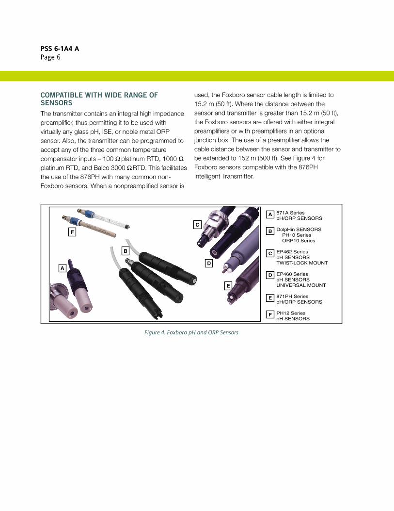
COMPATIBLE WITH WIDE RANGE OF SENSORS
The transmitter contains an integral high impedance preamplifier, thus permitting it to be used with virtually any glass pH, ISE, or noble metal ORP sensor. Also, the transmitter can be programmed to accept any of the three common temperature compensator inputs – 100 Ω platinum RTD, 1000 Ω platinum RTD, and Balco 3000 Ω RTD. This facilitates the use of the 876PH with many common non-Foxboro sensors. When a nonpreamplified sensor is
used, the Foxboro sensor cable length is limited to 15.2 m (50 ft). Where the distance between the sensor and transmitter is greater than 15.2 m (50 ft), the Foxboro sensors are offered with either integral preamplifiers or with preamplifiers in an optional junction box. The use of a preamplifier allows the cable distance between the sensor and transmitter to be extended to 152 m (500 ft). See Figure 4 for Foxboro sensors compatible with the 876PH Intelligent Transmitter.
Figure 4. Foxboro pH and ORP Sensors
871A SeriespH/ORP SENSORS
DolpHin SENSORS PH10 Series ORP10 Series
EP462 SeriespH SENSORSTWIST-LOCK MOUNT
EP460 SeriespH SENSORSUNIVERSAL MOUNT
871PH SeriespH/ORP SENSORS
PH12 SeriespH SENSORS
A
E
F
D
C
B
A
E
D
C
B
F
PSS 6-1A4 APage 7
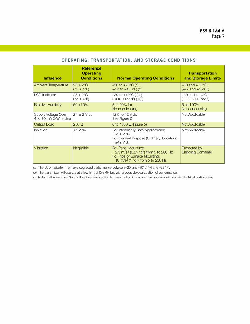
OPERATING, TRANSPORTATION, AND STORAGE CONDITIONS
(a) The LCD Indicator may have degraded performance between –20 and –30°C (–4 and –22 °F).
(b) The transmitter will operate at a low limit of 0% RH but with a possible degradation of performance.
(c) Refer to the Electrical Safety Specifications section for a restriction in ambient temperature with certain electrical certifications.
Influence
Reference Operating Conditions Normal Operating Conditions
Transportationand Storage Limits
Ambient Temperature 23 ± 2°C(73 ± 4°F)
–30 to +70°C (c)(–22 to +158°F) (c)
–30 and + 70°C(–22 and +158°F)
LCD Indicator 23 ± 2°C(73 ± 4°F)
–20 to +70°C (a)(c)(–4 to +158°F) (a)(c)
–30 and + 70°C(–22 and +158°F)
Relative Humidity 50 ±10% 5 to 90% (b)Noncondensing
5 and 90%Noncondensing
Supply Voltage Over 4 to 20 mA 2-Wire Line
24 ± 2 V dc 12.8 to 42 V dcSee Figure 5
Not Applicable
Output Load 250 Ω 0 to 1300 Ω (Figure 5) Not Applicable
Isolation ±1 V dc For Intrinsically Safe Applications:±24 V dc
For General Purpose (Ordinary) Locations:±42 V dc
Not Applicable
Vibration Negligible For Panel Mounting:2.5 m/s2 (0.25 “g”) from 5 to 200 Hz
For Pipe or Surface Mounting:10 m/s2 (1 “g”) from 5 to 200 Hz
Protected byShipping Container
PSS 6-1A4 APage 8
PERFORMANCE SPECIFICATIONS
(Transmitter Specif icat ions under Reference Operat ing Condit ions unless otherwise specif ied. Refer to Sensor Literature for Sensor Specif icat ions.)
Accuracy – Digital Measurement (Includes
Linearity, Hysteresis, and Repeatability)
pH MEASUREMENT (at 25°C/77°F Reference)
±0.009 pH with 3-wire, 1000 ohm RTD
±0.011 pH with 3-Wire, 100 Ω RTD
±0.011 pH with 2-Wire, 3000 Ω BALCO RTD
±0.015 pH with 2-Wire, 1000 Ω RTD
±0.020 pH with 2-Wire, 100 Ω RTD
ORP MEASUREMENT (at 25°C/77°F Reference)
±0.5 mV
ISE MEASUREMENT (at 25°C/77°F Reference)
±0.5 mV
Accuracy - Analog Output
Analog output accuracy is equal to the digital measurement accuracy plus an additional 0.04% of full span (4 to 20 mA).
Accuracy – Solution Temperature (at 25°C/77°F
Reference)
WITH 3-WIRE 1000 Ω PLATINUM RTD
±0.03°C (±0.05°F)
WITH 3-WIRE 100 Ω PLATINUM RTD
±0.1°C (±0.18°F)
WITH 2-WIRE 3000 Ω BALCO RTD
±0.1°C (±0.18°F)
WITH 2-WIRE 1000 Ω PLATINUM RTD
±0.3°C (±0.5°F)
WITH 2-WIRE 100 Ω PLATINUM RTD
±0.5°C (±0.9°F)
Ambient Temperature Effect on Digital
Measurement Accuracy
The effect listed below is for a 28°C (50°F) change in transmitter temperature within Normal Operating Condition limits.
pH MEASUREMENT
±0.009 pH with 3-wire, 1000 Ω RTD
ORP MEASUREMENT
±0.5 mV
ISE MEASUREMENT
±0.5 mV
Ambient Temperature Effect on Analog Output
Accuracy
Digital Measurement effect plus an additional ±0.01% per °C.
Ambient Temperature Effect on Solution
Temperature Accuracy
The effect below is for a 28°C (50°F) change in transmitter temperature within Normal Operating Condition limits.
WITH 3-WIRE 1000 Ω PLATINUM RTD
±0.03°C (±0.05°F)
WITH 3-WIRE 100 Ω PLATINUM RTD
±0.1°C (±0.18°F)
WITH 2-WIRE 3000 Ω BALCO RTD
±0.1°C (±0.18°F)
WITH 2-WIRE 1000 Ω PLATINUM RTD
±0.3°C (±0.5°F)
WITH 2-WIRE 100 Ω PLATINUM RTD
±0.5°C (±0.9°F)
Relative Humidity Effect (5 to 95% RH)
No effect for noncondensing environments.
PSS 6-1A4 APage 9
PERFORMANCE SPECIFICATIONS (CONT.)
Supply Voltage and Load Effect
DIGITAL
Less than 0.005% of full scale/V
ANALOG
Less than 0.005% of analog scale/V, inaddition to digital effect.
Mounting Position Effect
Transmitter meets reference accuracy specifications for all mounting positions.
Output Noise
Included in reference accuracy specifications.
Response Time
Response time is defined as a 90% response to a stepped input change.
pH, ORP, AND ISE MEASUREMENT
(NO TEMPERATURE COMPENSATION)
less than 2 seconds with no dampingRTD MEASUREMENT
less than 5 seconds.
Measurement Stability
Stability listed is after six months (noncumulative).
pH MEASUREMENT
±0.009 pH at 25°C with 3-Wire 1000 Ω RTD
ORP MEASUREMENT
±0.5 mV at 25°C
ISE MEASUREMENT
±0.5 mV at 25°C
Temperature Stability
±0.05°C after six months (noncumulative)
Common Mode Rejection
120 dB, dc; or 50/60 Hz, ac; between loop and sensor (42 volts peak)
Minimum Output Span
pH MEASUREMENT
0.5 pH
ORP MEASUREMENT
32 mV
ISE MEASUREMENT
Scale - 9999. ppmMinimum Span = 80 ppm
Scale - 999.9 ppmMinimum Span = 8 ppm
Scale - 99.99 ppmMinimum Span = 0.8 ppm
Scale - 9.999 ppmMinimum Span = 0.08 ppm
Scale - 0.9999 ppmMinimum Span = 0.008 ppm
NAMUR Compliance
The transmitter complies with the following NAMUR Standards:
NAMUR NE 43 for analog overrange and underrange annunciations
NAMUR NE 21 for interference immunity requirements
Electromagnetic Compatibility (EMC)
The transmitter, when installed in accordance with MI 611-262, complies with the EMC requirements of European EMC Directive 2004/108/EC by conforming to the following EN Standard: EN 61326-1:2006.
PSS 6-1A4 APage 10
FUNCTIONAL SPECIFICATIONS
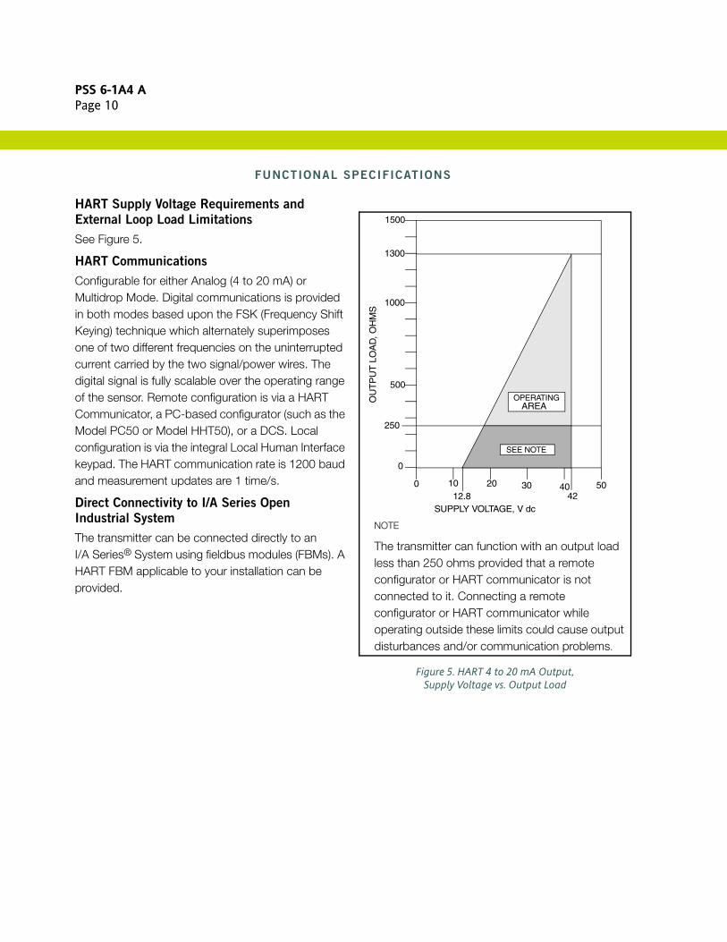
HART Supply Voltage Requirements and
External Loop Load Limitations
See Figure 5.
HART Communications
Configurable for either Analog (4 to 20 mA) or Multidrop Mode. Digital communications is provided in both modes based upon the FSK (Frequency Shift Keying) technique which alternately superimposes one of two different frequencies on the uninterrupted current carried by the two signal/power wires. The digital signal is fully scalable over the operating range of the sensor. Remote configuration is via a HART Communicator, a PC-based configurator (such as the Model PC50 or Model HHT50), or a DCS. Local configuration is via the integral Local Human Interface keypad. The HART communication rate is 1200 baud and measurement updates are 1 time/s.
Direct Connectivity to I/A Series Open
Industrial System
The transmitter can be connected directly to an I/A Series® System using fieldbus modules (FBMs). A HART FBM applicable to your installation can be provided.
Figure 5. HART 4 to 20 mA Output, Supply Voltage vs. Output Load
NOTE
The transmitter can function with an output load less than 250 ohms provided that a remote configurator or HART communicator is not connected to it. Connecting a remote configurator or HART communicator while operating outside these limits could cause output disturbances and/or communication problems.
SUPPLY VOLTAGE, V dc
OU
TP
UT
LO
AD
, OH
MS
0
1000
250
1300
500
0 10 20 30 4042
5012.8
OPERATINGAREA
SEE NOTE
1500
PSS 6-1A4 APage 11
FUNCTIONAL SPECIFICATIONS (CONT.)
Digital Output
1st DIGITAL MEASUREMENT
Independently assignable to pH, ORP, ISE, electrode voltage (absolute), temperature sensor resistance, glass electrode resistance, reference electrode resistance, or solution temperature. Also, the primary measurement (PV) is automatically assigned as the analog output.
2nd, 3rd, AND 4th DIGITAL MEASUREMENTS
Independently assignable to pH, ORP, ISE, electrode voltage (absolute), temperature sensor resistance, glass electrode resistance, reference electrode resistance, or solution temperature.
FACTORY DEFAULT SETTINGS
-PV = pH, ORP, or ISE Measurement
-SV = Solution Temperature
-TV = Electrode Voltage (absolute)
-4V = Temperature Sensor Resistance
Analog Output Configurable to pH, ORP, ISE, or Temperature. Linear output within measurement range. Analog output is configurable for Fail Safe. Analog output hold function.
Output Hold
Output Hold is a feature that allows sensor maintenance such as cleaning or calibration without control system upsets. Both digital and analog outputs can be configured to output hold.
OFF: The dynamic output tracks the live sensor readings.
PRESENT: The output remains frozen at the last value when output hold was invoked.
MANUAL: Output held at a preconfigured value.
Output hold can also be configured for automatic engagement during calibration and configuration sessions.
Fail Safe Output
Fail Safe output is configurable to OFF, FAIL LOW, or FAIL HIGH. The factory default is OFF.
OFF: The analog output continues to produce the available measurement without necessarily indicating a failure.
FAIL LOW or FAIL HIGH: User-configurable to Fail Low (3.6 mA) or Fail High (22 mA) upon failure, consistent with NAMUR Standard NE 43. The factory default is Fail Low.
Measurement Range – Selectable
pH (HYDROGEN ION CONCENTRATION)
–2 to +16 pH
ORP (OXIDATION REDUCTION POTENTIAL)
–2000 to +2000 mV
ISE (ION SELECTIVE ELECTRODE
CONCENTRATION)
0 to 9999 ppm
SOLUTION TEMPERATURE
–30 to +200°C (–22 to +392°F)
Measurement Damping
Measurement damping is continuously adjustable from 1 to 300 seconds.
Temperature Inputs
Factory precalibrated.
100 Ω platinum RTD, two or three wires 1000 Ω platinum RTD, two or three wires 3000 Ω Balco RTD, two wire
Input Impedance
1012 Ω minimum on both pH electrode and reference electrode inputs (with or without external amplifier); screen (shield) drive provided.

PSS 6-1A4 APage 12
FUNCTIONAL SPECIFICATIONS (CONT.)
Temperature Compensation
pH AND ISE COMPENSATION
Adjusts the Nernst slope factor to correct for the variation of the measuring electrode's potential with temperature. Thus, the displayed pH or ISE concentration is the actual measurement of the solution at process temperatures between -30 to +200°C (-22 to +392°F). Optional temperature compensations for 1 ppm ammonia and user-programmed custom curves are available.
ORP COMPENSATION
No temperature compensation is applied to the ORP measurement.
Temperature Compensation Range For pH or ISE –30 to +200°C (-22 to +392°F) For Ammonia: 0 to 100°C (32 to 212°F)
Precalibrated Measurement Range
The transmitter includes a factory ±2000 mV calibration for all measurements.
Auto Buffer Recognition
Transmitter has six tables of preprogrammed pH buffer values, identified as American, European, National Institute of Standards and Testing (NIST), DIN, JIS, and Merck. Also, seven user programmable tables are available that contain value sets of pH and temperature.
Sensor Compatibility DolpHin PH10 (pH) and ORP10 (ORP) PH12 (pH and ORP) 871PH (pH or ORP) 871A (pH or ORP) EP459A (Fluoride) EP460 (pH) EP462 (pH) EP466 (pH) Non-Foxboro sensors w/o integral preamplifiers,
and with compatible temperature sensors.
Continuous Diagnostics (Digital and Analog)
Complete check every eight seconds for diagnostics listed below unless otherwise noted. When diagnostics fail, the most severe failure is displayed. Additional information can then be obtained in the diagnostics menu. All diagnostic failures are reported via the digital protocol. Many will also cause an analog Fail Safe condition as noted below.
Background Sensor Diagnostics Broken Glass Electrode, Fail Safe, 4 seconds Liquid Leakage into Sensor, Fail Safe Measurement Range Checks (outside
±2000 mV), Fail Safe Temperature Sensor Range checks (short, open,
off table), Fail Safe Failed Preamplifier, Fail Safe Fouled or Dry Reference Junction
NOTEFail Safe = This diagnostic will cause the output to go to Fail Safe if Fail Safe is configured ON.
Background Electronics Self-Diagnostics
(All Fail Safe) Checksum, EEPROM, EPROM, and RAM Image
of Database Code Space Checksum Stack Checking Watch-Dog Timer Verify Readable Processor Registers Analog to Digital Converter
Application Diagnostics Compensation Range Checks (outside selected
range for temperature compensation or concentration). Causes Fail Safe., if enabled.
Analog Output Overrange and Underrange. Causes Fail Safe, if enabled.
PSS 6-1A4 APage 13
FUNCTIONAL SPECIFICATIONS (CONT.)
Calibration Diagnostics Measurement Slope (pH and ISE only) Aging Glass Electrode
Diagnostics Status
Indicators available to the user in status mode by pressing the DOWN ARROW key.
Solution Temperature Display Absolute Input (mV) Display Status Measurement Slope % Display (pH
and ISE only) Status Time of Last Calibration Display Other Device Status Displays
Valid Configuration Check
Once a user configuration session is complete, the configuration is validated as a whole. If valid, the user is given the choice to accept the configuration or abort and return to the previous configuration.
If any part of the configuration is invalid, the problem is indicated to the user and the user can choose to fix the problem or abort.
Calibration
For each user calibration type, the user is provided with detailed, step by step instructions on screen.
History Log
A history log of the 100 most recent events is stored in nonvolatile memory. Events include power up, diagnostic detection, pass code entry, configuration, calibration, and output hold entry and exit.
Passcode
Two configurable user passcode levels are supported.
Write Protect Jumper
A write protect jumper provides additional security by allowing the user to prevent the local indicator (configurator) and remote configurator from writing to the electronics. This write protection capability meets the security requirements of ISA-584.01-1986.
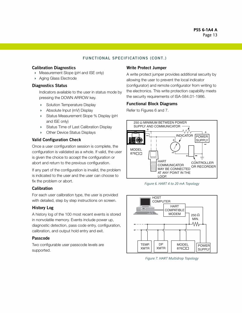
Functional Block Diagrams
Refer to Figures 6 and 7.
Figure 6. HART 4 to 20 mA Topology
Figure 7. HART Multidrop Topology
INDICATOR
HARTCOMMUNICATORMAY BE CONNECTEDAT ANY POINT IN THELOOP.
CONTROLLEROR RECORDER
+
+
+
+
250 Ω MINIMUM BETWEEN POWERSUPPLY AND COMMUNICATOR
POWERSUPPLY
MODEL876
HARTCOMPATIBLE
MODEM
DPXMTR
POWERSUPPLY
TEMP.XMTR
250 MIN.
HOST COMPUTER
MODEL876
PSS 6-1A4 APage 14
PHYSICAL SPECIFICATIONS
Transmitter Enclosure
The transmitter enclosure comprises a housing and hinged bezel assembly. The bezel assembly attaches to the housing with captive screws, with a gasket seal between them.
HOUSING AND BEZEL MATERIAL
Aluminum alloy (with a maximum copper content of 1%).
Clear lexan window on bezel assembly.
GASKET MATERIAL
Silicone Rubber
Environmental and Corrosion Resistant
Protection
The enclosure has the dusttight and weatherproof rating of IP66 as defined by IEC 60529 and provides the environmental and corrosion resistant protection rating of NEMA 4X.
Storm Door (Optional)
Made from a 0.90 inch thick, clear plastic with a polished finish.
KeypadDurable, clear thermoplastic
DisplayLiquid Crystal Display (LCD)
Transmitter Mounting
Transmitter can be panel or surface-mounted, or mounted to a DN 50 or 2-in pipe. A bracket is provided for surface or pipe mounting. See “Dimensions–Nominal” section for details.
Sensor Cable Length
SENSOR WITH PREAMPLIFIER
152 m (500 ft) maximum. Note thatpreamplifier may also be in a remote junctionbox.
SENSOR WITHOUT PREAMPLIFIER
15.2 m (50 ft) maximum
Approximate Weight
PANEL MOUNTED TRANSMITTER
3.1 kg (6.8 lb)SURFACE/PIPE MOUNTED TRANSMITTER
3.7 kg (8.1 lb); includes mounting bracket
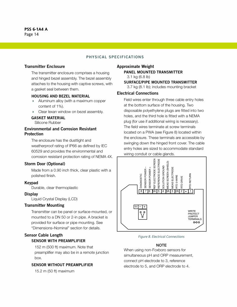
Electrical Connections
Field wires enter through three cable entry holes at the bottom surface of the housing. Two disposable polyethylene plugs are fitted into two holes, and the third hole is fitted with a NEMA plug (for use if additional wiring is necessary). The field wires terminate at screw terminals located on a PWA (see Figure 8) located within the enclosure. These terminals are accessible by swinging down the hinged front cover. The cable entry holes are sized to accommodate standard wiring conduit or cable glands.
Figure 8. Electrical Connections
NOTEWhen using non-Foxboro sensors for simultaneous pH and ORP measurement, connect pH electrode to 3, reference electrode to 5, and ORP electrode to 4.
8 7 6 5A 5 4 3A 3 2A 2 1R
TD
RE
TU
RN
RT
D D
RIV
E
RT
D 3
-WIR
E
ME
AS
ELE
CT
RO
DE
ME
AS
SC
RE
EN
(S
HIE
LD)
SO
LUT
ION
GR
OU
ND
RE
FE
RE
NC
E E
LEC
TR
OD
E
RE
F E
LEC
TR
OD
E S
CR
EE
N
SE
NS
OR
PO
WE
R +
SE
NS
OR
PO
WE
R –
DIA
GN
OS
TIC
+–WRITEPROTECTJUMPERTERMINALS
PSS 6-1A4 APage 15
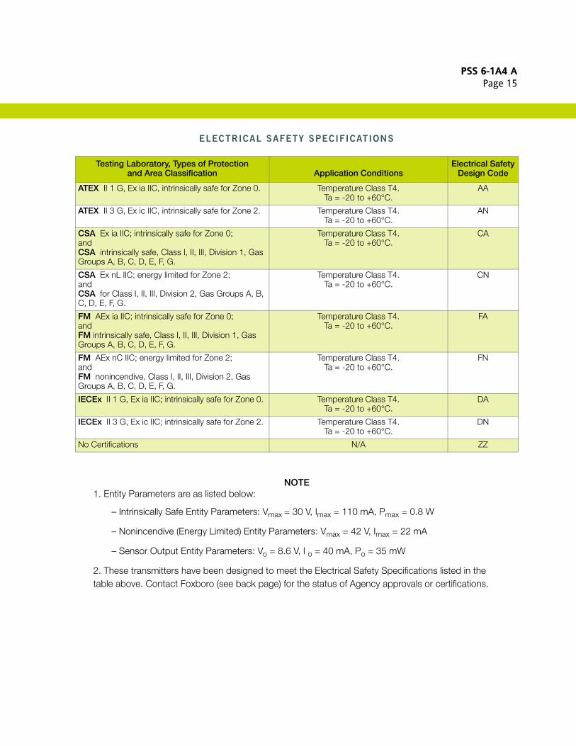
ELECTRICAL SAFETY SPECIFICATIONS
NOTE1. Entity Parameters are as listed below:
– Intrinsically Safe Entity Parameters: Vmax = 30 V, Imax = 110 mA, Pmax = 0.8 W
– Nonincendive (Energy Limited) Entity Parameters: Vmax = 42 V, Imax = 22 mA
– Sensor Output Entity Parameters: Vo = 8.6 V, I o = 40 mA, Po = 35 mW
2. These transmitters have been designed to meet the Electrical Safety Specifications listed in the table above. Contact Foxboro (see back page) for the status of Agency approvals or certifications.
Testing Laboratory, Types of Protectionand Area Classification Application Conditions
Electrical SafetyDesign Code
ATEX II 1 G, Ex ia IIC, intrinsically safe for Zone 0. Temperature Class T4. Ta = -20 to +60°C.
AA
ATEX II 3 G, Ex ic IIC, intrinsically safe for Zone 2. Temperature Class T4. Ta = -20 to +60°C.
AN
CSA Ex ia IIC; intrinsically safe for Zone 0; andCSA intrinsically safe, Class I, II, III, Division 1, Gas Groups A, B, C, D, E, F, G.
Temperature Class T4. Ta = -20 to +60°C.
CA
CSA Ex nL IIC; energy limited for Zone 2;andCSA for Class I, II, III, Division 2, Gas Groups A, B, C, D, E, F, G.
Temperature Class T4. Ta = -20 to +60°C.
CN
FM AEx ia IIC; intrinsically safe for Zone 0; andFM intrinsically safe, Class I, II, III, Division 1, Gas Groups A, B, C, D, E, F, G.
Temperature Class T4. Ta = -20 to +60°C.
FA
FM AEx nC IIC; energy limited for Zone 2; andFM nonincendive, Class I, II, III, Division 2, Gas Groups A, B, C, D, E, F, G.
Temperature Class T4. Ta = -20 to +60°C.
FN
IECEx II 1 G, Ex ia IIC; intrinsically safe for Zone 0. Temperature Class T4. Ta = -20 to +60°C.
DA
IECEx II 3 G, Ex ic IIC; intrinsically safe for Zone 2. Temperature Class T4. Ta = -20 to +60°C.
DN
No Certifications N/A ZZ
PSS 6-1A4 APage 16
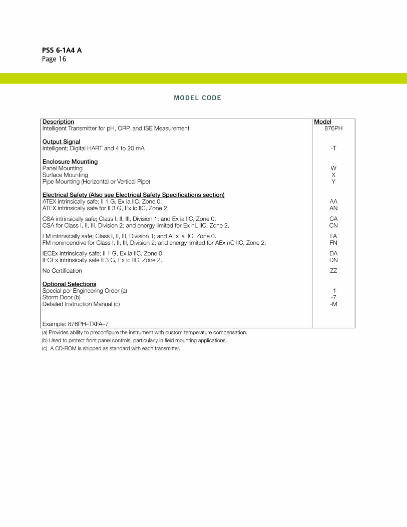
MODEL CODE
(a) Provides ability to preconfigure the instrument with custom temperature compensation.
(b) Used to protect front panel controls, particularly in field mounting applications.
(c) A CD-ROM is shipped as standard with each transmitter.
Description ModelIntelligent Transmitter for pH, ORP, and ISE Measurement 876PH
Output SignalIntelligent; Digital HART and 4 to 20 mA -T
Enclosure MountingPanel Mounting WSurface Mounting XPipe Mounting (Horizontal or Vertical Pipe) Y
Electrical Safety (Also see Electrical Safety Specifications section)ATEX intrinsically safe; II 1 G, Ex ia IIC, Zone 0. AAATEX intrinsically safe for II 3 G, Ex ic IIC, Zone 2. AN
CSA intrinsically safe; Class I, II, III, Division 1; and Ex ia IIC, Zone 0. CACSA for Class I, II, III, Division 2; and energy limited for Ex nL IIC, Zone 2. CN
FM intrinsically safe; Class I, II, III, Division 1; and AEx ia IIC, Zone 0. FAFM nonincendive for Class I, II, III, Division 2; and energy limited for AEx nC IIC, Zone 2. FN
IECEx intrinsically safe; II 1 G, Ex ia IIC, Zone 0. DAIECEx intrinsically safe II 3 G, Ex ic IIC, Zone 2. DN
No Certification ZZ
Optional SelectionsSpecial per Engineering Order (a) -1Storm Door (b) -7Detailed Instruction Manual (c) -M
Example: 876PH–TXFA–7

PSS 6-1A4 APage 17
DIMENSIONS–NOMINAL
TRANSMITTER ASSEMBLY
mmin
1937.6
2188.6
1044.1
100.4
OPTIONAL STORMDOOR OPENS UPWARD
1455.7
FOUR BOSSES ON REAR SURFACETAPPED 0.250-20, 6.4 mm (0.25 in)DEEP ARE USED FOR SURFACE ORPIPE MOUNTING OF TRANSMITTER.CENTERS OF BOSSES ARE ON A89 mm (3.5 in) BOLT CIRCLE.
GASKET BETWEENCASE AND HINGEDFRONT COVER.
1917.5
26710.5
381.5
381.5
411.6
TWO 22 mm (0.87 in) DIAMETERHOLES FOR FIELD WIRING ENTRY.NEMA PLUG IN CENTER HOLE CANBE REMOVED FOR ADDITIONAL WIRING.
FRONT COVERHINGES DOWNWARD.
PSS 6-1A4 APage 18
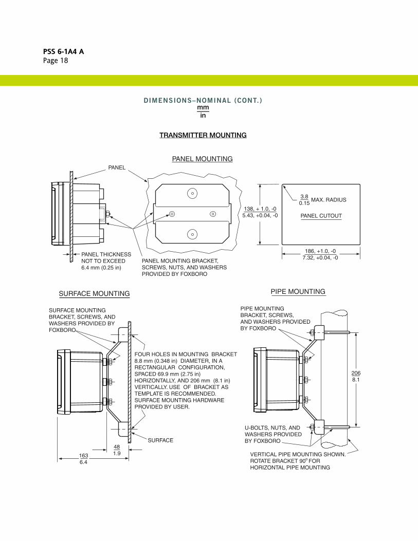
DIMENSIONS–NOMINAL (CONT.)mmin
TRANSMITTER MOUNTING
PANEL CUTOUT
MAX. RADIUS3.80.15
138, + 1.0, -05.43, +0.04, -0
186, +1.0, -07.32, +0.04, -0
2068.1
U-BOLTS, NUTS, ANDWASHERS PROVIDEDBY FOXBORO
VERTICAL PIPE MOUNTING SHOWN.ROTATE BRACKET 90 FORHORIZONTAL PIPE MOUNTING
PIPE MOUNTINGBRACKET, SCREWS, AND WASHERS PROVIDED BY FOXBORO
PIPE MOUNTING
PANEL MOUNTINGPANEL
PANEL THICKNESSNOT TO EXCEED6.4 mm (0.25 in)
PANEL MOUNTING BRACKET,SCREWS, NUTS, AND WASHERSPROVIDED BY FOXBORO
SURFACE MOUNTINGBRACKET, SCREWS, ANDWASHERS PROVIDED BYFOXBORO
1636.4
481.9
FOUR HOLES IN MOUNTING BRACKET 8.8 mm (0.348 in) DIAMETER, IN ARECTANGULAR CONFIGURATION, SPACED 69.9 mm (2.75 in) HORIZONTALLY, AND 206 mm (8.1 in) VERTICALLY. USE OF BRACKET AS TEMPLATE IS RECOMMENDED. SURFACE MOUNTING HARDWAREPROVIDED BY USER.
SURFACE
SURFACE MOUNTING
PSS 6-1A4 APage 19
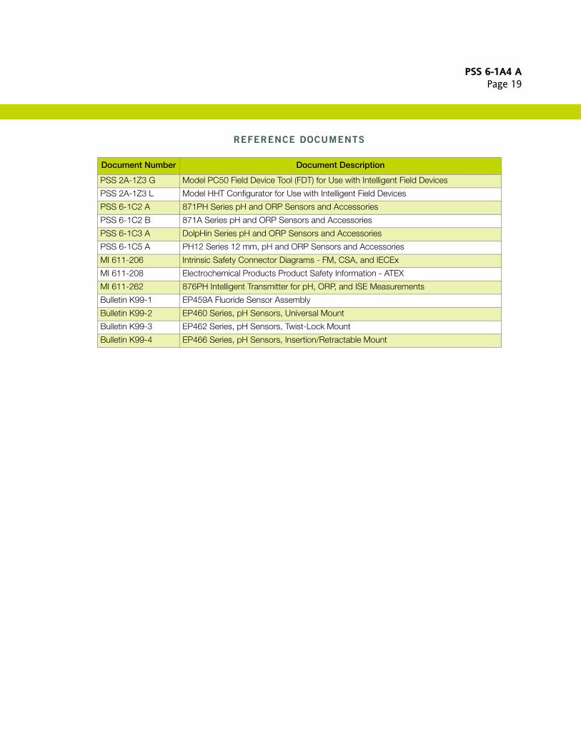
REFERENCE DOCUMENTS
Document Number Document Description
PSS 2A-1Z3 G Model PC50 Field Device Tool (FDT) for Use with Intelligent Field Devices
PSS 2A-1Z3 L Model HHT Configurator for Use with Intelligent Field Devices
PSS 6-1C2 A 871PH Series pH and ORP Sensors and Accessories
PSS 6-1C2 B 871A Series pH and ORP Sensors and Accessories
PSS 6-1C3 A DolpHin Series pH and ORP Sensors and Accessories
PSS 6-1C5 A PH12 Series 12 mm, pH and ORP Sensors and Accessories
MI 611-206 Intrinsic Safety Connector Diagrams - FM, CSA, and IECEx
MI 611-208 Electrochemical Products Product Safety Information - ATEX
MI 611-262 876PH Intelligent Transmitter for pH, ORP, and ISE Measurements
Bulletin K99-1 EP459A Fluoride Sensor Assembly
Bulletin K99-2 EP460 Series, pH Sensors, Universal Mount
Bulletin K99-3 EP462 Series, pH Sensors, Twist-Lock Mount
Bulletin K99-4 EP466 Series, pH Sensors, Insertion/Retractable Mount
PSS 6-1A4 APage 20
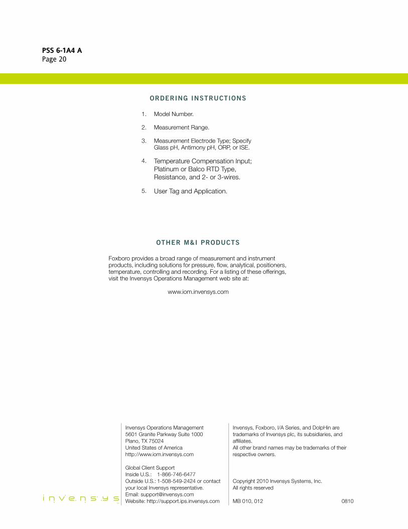
ORDERING INSTRUCTIONS
OTHER M&I PRODUCTS
1. Model Number.
2. Measurement Range.
3. Measurement Electrode Type; Specify Glass pH, Antimony pH, ORP, or ISE.
4. Temperature Compensation Input; Platinum or Balco RTD Type, Resistance, and 2- or 3-wires.
5. User Tag and Application.
Foxboro provides a broad range of measurement and instrument products, including solutions for pressure, flow, analytical, positioners, temperature, controlling and recording. For a listing of these offerings, visit the Invensys Operations Management web site at:
www.iom.invensys.com
Invensys Operations Management5601 Granite Parkway Suite 1000Plano, TX 75024United States of Americahttp://www.iom.invensys.com
Global Client SupportInside U.S.: 1-866-746-6477Outside U.S.: 1-508-549-2424 or contact your local Invensys representative.Email: [email protected]: http://support.ips.invensys.com
Invensys, Foxboro, I/A Series, and DolpHin are trademarks of Invensys plc, its subsidiaries, and affiliates.All other brand names may be trademarks of their respective owners.
Copyright 2010 Invensys Systems, Inc.All rights reserved
MB 010, 012 0810