PSS 5000, Technical Manual - DOMS · PSS5000/TEMA/803046/18 For systems with CPB50x 9 of 161 PSS...
161
Date Document number December 30, 2016 PSS5000/TEMA/803046/18 Doms ApS Formervangen 28 DK-2600 Glostrup Tel. +45 4329 9490 [email protected] [email protected] PSS 5000 Technical Manual For systems with CPB50x
Transcript of PSS 5000, Technical Manual - DOMS · PSS5000/TEMA/803046/18 For systems with CPB50x 9 of 161 PSS...

DateDocument number
December 30, 2016PSS5000/TEMA/803046/18
Doms ApS Formervangen 28DK-2600 Glostrup
Tel. +45 4329 9490 [email protected]@doms.com
PSS 5000
Technical ManualFor systems with CPB50x

PSS 5000 – Technical ManualPreface
Legal Notices
Copyright Statement This Doms documentation is owned by Doms or its licensors and is protected.Your right to use this documentation is subject to the limitations and restric-tions imposed by applicable licenses and copyright laws. Unauthorized repro-duction, modification, distribution, display or other use of this documentationmay result in criminal and civil penalties.
About This Documentation
Purpose This documentation provides a general description of the PSS 5000 systemcomponents and service facilities. It describes the functions available with thePSS 5000 and contains procedures, which describe how to use the variousfunctions. For documentation about specific system details, please see the documentslisted in the Software Release Document for the actual application or, alterna-tively, look at ‘D.3 Referenced Documents’ on page 149.
Audience The content of this documentation is designed for technicians who need toconfigure or service systems using PSS 5000.It is assumed that the reader has a basic knowledge of standard PC technolo-gies, such as Windows and Internet browsers, and has attended a foundationcourse that introduces the workings of the PSS 5000.
2 of 161 PSS5000/TEMA/803046/18

PSS 5000 – Technical ManualContents
Contents
Legal Notices . . . . . . . . . . . . . . . . . . . . . . . . . . . . . . . . . . . . . . . . . . . . . 2About This Documentation . . . . . . . . . . . . . . . . . . . . . . . . . . . . . . . . . . . 2
Part I: Getting to Know the PSS 5000 . . . . . . . . . . . . . . . . . . . . . . . .7
1 Architectural Overview . . . . . . . . . . . . . . . . . . . . . . . . . . . . . . . . . . . . 8
1.1 PSS 5000 Without a Network Connection . . . . . . . . . . . . . . . . . . . . . . . 81.2 PSS 5000 With a Network Connection . . . . . . . . . . . . . . . . . . . . . . . . . . 91.3 PSS 5000 in a Mixed Configuration . . . . . . . . . . . . . . . . . . . . . . . . . . . 10
2 System Description . . . . . . . . . . . . . . . . . . . . . . . . . . . . . . . . . . . . . 11
2.1 PSS 5000 Hardware . . . . . . . . . . . . . . . . . . . . . . . . . . . . . . . . . . . . . . . 112.1.1 PSS 5000 Cabinets . . . . . . . . . . . . . . . . . . . . . . . . . . . . . . . . 112.1.2 PSS 5000 Computer Processor Boards . . . . . . . . . . . . . . . . . 132.1.3 Hardware Interface Modules . . . . . . . . . . . . . . . . . . . . . . . . . . 142.1.4 Service and Maintenance . . . . . . . . . . . . . . . . . . . . . . . . . . . . 15
2.2 PSS 5000 Software . . . . . . . . . . . . . . . . . . . . . . . . . . . . . . . . . . . . . . . 162.2.1 Virtual File System . . . . . . . . . . . . . . . . . . . . . . . . . . . . . . . . . 162.2.2 Memory Structure . . . . . . . . . . . . . . . . . . . . . . . . . . . . . . . . . . 172.2.3 The Software Components . . . . . . . . . . . . . . . . . . . . . . . . . . . 182.2.4 Web Server . . . . . . . . . . . . . . . . . . . . . . . . . . . . . . . . . . . . . . . 202.2.5 FTP Server . . . . . . . . . . . . . . . . . . . . . . . . . . . . . . . . . . . . . . . 202.2.6 Serial Server . . . . . . . . . . . . . . . . . . . . . . . . . . . . . . . . . . . . . . 212.2.7 Network Connection . . . . . . . . . . . . . . . . . . . . . . . . . . . . . . . . 21
3 Configuration and Service . . . . . . . . . . . . . . . . . . . . . . . . . . . . . . . . 22
3.1 Configuration and Service Menus Access . . . . . . . . . . . . . . . . . . . . . . 223.1.1 Local Service Panel . . . . . . . . . . . . . . . . . . . . . . . . . . . . . . . . 223.1.2 Web Service Pages . . . . . . . . . . . . . . . . . . . . . . . . . . . . . . . . 26
3.2 Software Changes . . . . . . . . . . . . . . . . . . . . . . . . . . . . . . . . . . . . . . . . 27
Part II: Using the Service Menus. . . . . . . . . . . . . . . . . . . . . . . . . . . .29
4 Information (Menu 1) . . . . . . . . . . . . . . . . . . . . . . . . . . . . . . . . . . . . 30
4.1 Program Versions (Menu 1.1) . . . . . . . . . . . . . . . . . . . . . . . . . . . . . . . 304.2 Board Info (Menu 1.2) . . . . . . . . . . . . . . . . . . . . . . . . . . . . . . . . . . . . . 31
4.2.1 Production (Menu 1.2.1) . . . . . . . . . . . . . . . . . . . . . . . . . . . . . 314.2.2 Sealing Switch (Menu 1.2.2) . . . . . . . . . . . . . . . . . . . . . . . . . . 33
4.3 SW Blocks (Menu 1.3) . . . . . . . . . . . . . . . . . . . . . . . . . . . . . . . . . . . . . 344.4 Protocols (Menu 1.4) . . . . . . . . . . . . . . . . . . . . . . . . . . . . . . . . . . . . . . 354.5 LAM (Menu 1.5) . . . . . . . . . . . . . . . . . . . . . . . . . . . . . . . . . . . . . . . . . . 35
5 Installation (Menu 2) . . . . . . . . . . . . . . . . . . . . . . . . . . . . . . . . . . . . . 36
PSS5000/TEMA/803046/18 For systems with CPB50x 3 of 161

PSS 5000 – Technical ManualContents
5.1 Protocol to Port Assignment (Menu 2.1) . . . . . . . . . . . . . . . . . . . . . . . 365.1.1 Changing Protocol to Port Assignments . . . . . . . . . . . . . . . . . 375.1.2 Setting the Protocol Parameter Values . . . . . . . . . . . . . . . . . . 405.1.3 Limitations . . . . . . . . . . . . . . . . . . . . . . . . . . . . . . . . . . . . . . . 41
5.2 Date and Time (Menu 2.2) . . . . . . . . . . . . . . . . . . . . . . . . . . . . . . . . . . 425.3 Communication Setup (Menu 2.3) . . . . . . . . . . . . . . . . . . . . . . . . . . . . 43
5.3.1 TCP/IP Setup (Menu 2.3.1) . . . . . . . . . . . . . . . . . . . . . . . . . . 445.3.2 Service Port Setup (Menu 2.3.2) . . . . . . . . . . . . . . . . . . . . . . 475.3.3 Datalink Timeout for Serial Driver (Menu 2.3.3) . . . . . . . . . . . 485.3.4 Service Port Protocol (Menu 2.3.4) . . . . . . . . . . . . . . . . . . . . . 495.3.5 Menu 2.3.5 – Reserved for Future Use . . . . . . . . . . . . . . . . . 505.3.6 Dialup Setup/Test (Menu 2.3.6) . . . . . . . . . . . . . . . . . . . . . . . 505.3.7 Online/Offline Event Time (Menu 2.3.7) . . . . . . . . . . . . . . . . . 51
5.4 System Profile (Menu 2.4) . . . . . . . . . . . . . . . . . . . . . . . . . . . . . . . . . . 525.4.1 Password (Menu 2.4.1) . . . . . . . . . . . . . . . . . . . . . . . . . . . . . . 525.4.2 Name and Number (Menu 2.4.2) . . . . . . . . . . . . . . . . . . . . . . 565.4.3 POS Password (Menu 2.4.3) . . . . . . . . . . . . . . . . . . . . . . . . . 565.4.4 Web Preferences (Menu 2.4.4) . . . . . . . . . . . . . . . . . . . . . . . . 57
5.5 Application Setup (Menu 2.5) . . . . . . . . . . . . . . . . . . . . . . . . . . . . . . . . 575.6 Software Upload (Menu 2.6) . . . . . . . . . . . . . . . . . . . . . . . . . . . . . . . . 605.7 Peripheral Configuration (Menu 2.7) . . . . . . . . . . . . . . . . . . . . . . . . . . 65
5.7.1 Memory Module (Menu 2.7.1) . . . . . . . . . . . . . . . . . . . . . . . . . 655.8 Backup (Menu 2.8) . . . . . . . . . . . . . . . . . . . . . . . . . . . . . . . . . . . . . . . . 66
6 Operation (Menu 3) . . . . . . . . . . . . . . . . . . . . . . . . . . . . . . . . . . . . . . 69
6.1 Enter Fallback Mode (Menu 3.1) . . . . . . . . . . . . . . . . . . . . . . . . . . . . . 696.2 Grade Prices (Menu 3.2) . . . . . . . . . . . . . . . . . . . . . . . . . . . . . . . . . . . 716.3 FP Transactions (Menu 3.3) . . . . . . . . . . . . . . . . . . . . . . . . . . . . . . . . . 72
6.3.1 Monitor (Menu 3.3.1) . . . . . . . . . . . . . . . . . . . . . . . . . . . . . . . 726.3.2 Log (Menu 3.3.2) . . . . . . . . . . . . . . . . . . . . . . . . . . . . . . . . . . 73
6.4 Payment Server (Menu 3.4) . . . . . . . . . . . . . . . . . . . . . . . . . . . . . . . . . 736.5 Operation Mode (Menu 3.5) . . . . . . . . . . . . . . . . . . . . . . . . . . . . . . . . . 746.6 Menu 3.6 Reserved for Future Use . . . . . . . . . . . . . . . . . . . . . . . . . . . 756.7 Operational Status (Menu 3.7) . . . . . . . . . . . . . . . . . . . . . . . . . . . . . . . 766.8 TeleTerminal (Menu 3.8) . . . . . . . . . . . . . . . . . . . . . . . . . . . . . . . . . . . 776.9 Reconciliation Report (Menu 3.9) . . . . . . . . . . . . . . . . . . . . . . . . . . . . . 77
7 Reset (Menu 4) . . . . . . . . . . . . . . . . . . . . . . . . . . . . . . . . . . . . . . . . . 81
7.1 Soft Reset (Menu 4.1) . . . . . . . . . . . . . . . . . . . . . . . . . . . . . . . . . . . . . 817.2 Master Reset (Menu 4.2) . . . . . . . . . . . . . . . . . . . . . . . . . . . . . . . . . . . 827.3 Super Master Reset (Menu 4.3) . . . . . . . . . . . . . . . . . . . . . . . . . . . . . . 83
8 Diagnostics (Menu 5) . . . . . . . . . . . . . . . . . . . . . . . . . . . . . . . . . . . . 85
8.1 Forecourt Devices (Menu 5.1) . . . . . . . . . . . . . . . . . . . . . . . . . . . . . . . 858.1.1 Online List (Menu 5.1.1) . . . . . . . . . . . . . . . . . . . . . . . . . . . . . 858.1.2 Device Errors (Menu 5.1.2) . . . . . . . . . . . . . . . . . . . . . . . . . . . 878.1.3 Price Pole Test (Menu 5.1.3) . . . . . . . . . . . . . . . . . . . . . . . . . 888.1.4 Device Status (Menu 5.1.4) . . . . . . . . . . . . . . . . . . . . . . . . . . 908.1.5 Device Test (Menu 5.1.5) . . . . . . . . . . . . . . . . . . . . . . . . . . . . 93
8.2 System Logs (Menu 5.2) . . . . . . . . . . . . . . . . . . . . . . . . . . . . . . . . . . . 978.2.1 Upload Log (Menu 5.2.1) . . . . . . . . . . . . . . . . . . . . . . . . . . . . 978.2.2 Reset Logs (Menu 5.2.2) . . . . . . . . . . . . . . . . . . . . . . . . . . . . 988.2.3 Application Log (Menu 5.2.3) . . . . . . . . . . . . . . . . . . . . . . . . 1018.2.4 Access Log (Menu 5.2.4) . . . . . . . . . . . . . . . . . . . . . . . . . . . 1028.2.5 Board Error Log (Menu 5.2.5) . . . . . . . . . . . . . . . . . . . . . . . . 103
8.3 Communication (Menu 5.3) . . . . . . . . . . . . . . . . . . . . . . . . . . . . . . . . 1048.3.1 Ethernet Statistics (Menu 5.3.1) . . . . . . . . . . . . . . . . . . . . . . 1048.3.2 Port Statistics (Menu 5.3.2) . . . . . . . . . . . . . . . . . . . . . . . . . 1048.3.3 Protocols (Menu 5.3.3) . . . . . . . . . . . . . . . . . . . . . . . . . . . . . 105
8.4 Peep (Menu 5.4) . . . . . . . . . . . . . . . . . . . . . . . . . . . . . . . . . . . . . . . . . 106
4 of 161 For systems with CPB50x PSS5000/TEMA/803046/18

PSS 5000 – Technical ManualContents
8.5 Test (Menu 5.5) . . . . . . . . . . . . . . . . . . . . . . . . . . . . . . . . . . . . . . . . . 1098.5.1 Menu 5.5.1 . . . . . . . . . . . . . . . . . . . . . . . . . . . . . . . . . . . . . . 1098.5.2 Boot (Menu 5.5.2) . . . . . . . . . . . . . . . . . . . . . . . . . . . . . . . . . 1098.5.3 GDB (Menu 5.5.3) . . . . . . . . . . . . . . . . . . . . . . . . . . . . . . . . . 109
8.6 Peripherals (Menu 5.6) . . . . . . . . . . . . . . . . . . . . . . . . . . . . . . . . . . . . 1098.6.1 Online List (Menu 5.6.1) . . . . . . . . . . . . . . . . . . . . . . . . . . . . 1108.6.2 Errors (Menu 5.6.2) . . . . . . . . . . . . . . . . . . . . . . . . . . . . . . . . 1108.6.3 Memory Module (Menu 5.6.3) . . . . . . . . . . . . . . . . . . . . . . . . 112
9 W & M (Menu W) . . . . . . . . . . . . . . . . . . . . . . . . . . . . . . . . . . . . . . . . 114
9.1 LAM Version (Menu W.1) . . . . . . . . . . . . . . . . . . . . . . . . . . . . . . . . . . 1149.2 LAM Parameters (Menu W.2) . . . . . . . . . . . . . . . . . . . . . . . . . . . . . . . 1159.3 Memory Module Version (Menu W.3) . . . . . . . . . . . . . . . . . . . . . . . . . 1179.4 Program Upload Log (Menu W.4) . . . . . . . . . . . . . . . . . . . . . . . . . . . 1189.5 Recent Transactions (Menu W.5) . . . . . . . . . . . . . . . . . . . . . . . . . . . . 1199.6 Payment Log (Menu W.6) . . . . . . . . . . . . . . . . . . . . . . . . . . . . . . . . . 1199.7 Checking Devices (Menu W.7) . . . . . . . . . . . . . . . . . . . . . . . . . . . . . . 121
9.7.1 Display Error (Menu W.7.1) . . . . . . . . . . . . . . . . . . . . . . . . . 1229.7.2 Send Error Security Telegram (Menu W.7.2) . . . . . . . . . . . . 1239.7.3 LAM Code Error (Menu W.7.3) . . . . . . . . . . . . . . . . . . . . . . . 1239.7.4 RTC Error (Menu W.7.4) . . . . . . . . . . . . . . . . . . . . . . . . . . . . 1249.7.5 Trans Memory (Menu W.7.5) . . . . . . . . . . . . . . . . . . . . . . . . 125
Part III: Reference Information . . . . . . . . . . . . . . . . . . . . . . . . . . . . .128
A File Formats in the PSS 5000 . . . . . . . . . . . . . . . . . . . . . . . . . . . . . 129A.1 Recent Transactions File Format . . . . . . . . . . . . . . . . . . . . . . . . . . . . 129A.2 Transaction Log File Format . . . . . . . . . . . . . . . . . . . . . . . . . . . . . . . 130A.3 Upload Log File Format . . . . . . . . . . . . . . . . . . . . . . . . . . . . . . . . . . . 133
B Web Service Connections . . . . . . . . . . . . . . . . . . . . . . . . . . . . . . . 135B.1 PC and Browser Requirements . . . . . . . . . . . . . . . . . . . . . . . . . . . . . 135B.2 Ethernet Connections . . . . . . . . . . . . . . . . . . . . . . . . . . . . . . . . . . . . . 135B.3 Service Port Connection . . . . . . . . . . . . . . . . . . . . . . . . . . . . . . . . . . . 135
B.3.1 Modem Connection . . . . . . . . . . . . . . . . . . . . . . . . . . . . . . . . 135B.3.2 Null Modem Connection . . . . . . . . . . . . . . . . . . . . . . . . . . . . 136B.3.3 Installing Null Modem Connections . . . . . . . . . . . . . . . . . . . 136B.3.4 Dialling Up Using a Null Modem Connection . . . . . . . . . . . . 137
C Virtual File System . . . . . . . . . . . . . . . . . . . . . . . . . . . . . . . . . . . . . 140C.1 The Virtual File System . . . . . . . . . . . . . . . . . . . . . . . . . . . . . . . . . . . 140C.2 System Setup . . . . . . . . . . . . . . . . . . . . . . . . . . . . . . . . . . . . . . . . . . . 140C.3 Board Upload Log . . . . . . . . . . . . . . . . . . . . . . . . . . . . . . . . . . . . . . . 141C.4 Load Response . . . . . . . . . . . . . . . . . . . . . . . . . . . . . . . . . . . . . . . . . 142C.5 Hardware Information . . . . . . . . . . . . . . . . . . . . . . . . . . . . . . . . . . . . . 143C.6 Ok2load File . . . . . . . . . . . . . . . . . . . . . . . . . . . . . . . . . . . . . . . . . . . . 144C.7 Boot Information . . . . . . . . . . . . . . . . . . . . . . . . . . . . . . . . . . . . . . . . . 144C.8 LAM (Legal Authority Module) Information . . . . . . . . . . . . . . . . . . . . . 145C.9 Application Information . . . . . . . . . . . . . . . . . . . . . . . . . . . . . . . . . . . . 146C.10 Board Error Log . . . . . . . . . . . . . . . . . . . . . . . . . . . . . . . . . . . . . . . . . 146
D PSS 5000 Reference Information . . . . . . . . . . . . . . . . . . . . . . . . . 147D.1 List of Abbreviations . . . . . . . . . . . . . . . . . . . . . . . . . . . . . . . . . . . . . . 147D.2 List of Terms . . . . . . . . . . . . . . . . . . . . . . . . . . . . . . . . . . . . . . . . . . . . 148D.3 Referenced Documents . . . . . . . . . . . . . . . . . . . . . . . . . . . . . . . . . . . 149
E PSS 5000 XML Output . . . . . . . . . . . . . . . . . . . . . . . . . . . . . . . . . . 150E.1 Accessing the XML Files . . . . . . . . . . . . . . . . . . . . . . . . . . . . . . . . . . 150
PSS5000/TEMA/803046/18 For systems with CPB50x 5 of 161

PSS 5000 – Technical ManualContents
E.2 Config.xml File . . . . . . . . . . . . . . . . . . . . . . . . . . . . . . . . . . . . . . . . . . 151E.3 Site_sta.xml File . . . . . . . . . . . . . . . . . . . . . . . . . . . . . . . . . . . . . . . . . 151E.4 Site_rep.xml File . . . . . . . . . . . . . . . . . . . . . . . . . . . . . . . . . . . . . . . . . 152
F Revision Information . . . . . . . . . . . . . . . . . . . . . . . . . . . . . . . . . . . 154
Index . . . . . . . . . . . . . . . . . . . . . . . . . . . . . . . . . . . . . . . . . . . . . . . 156
6 of 161 For systems with CPB50x PSS5000/TEMA/803046/18

PSS5000/TEMA/803046/18 For systems with CPB50x 7 of 161
PSS 5000 – Technical Manual
Part I: Getting to Know the PSS 5000
• ‘1 Architectural Overview’ on page 8
• ‘2 System Description’ on page 11
• ‘3 Configuration and Service’ on page 22

PSS 5000 – Technical Manual1 Architectural Overview
1 Architectural Overview
List of PSS 5000 configurations
The PSS 5000 can be used in 3 basic configurations. These are described in thefollowing topics:• ‘1.1 PSS 5000 Without a Network Connection’ on page 8• ‘1.2 PSS 5000 With a Network Connection’ on page 9• ‘1.3 PSS 5000 in a Mixed Configuration’ on page 10
1.1 PSS 5000 Without a Network Connection
Illustration of a system using serial POS driver
This illustration shows how POS terminals can be used by connecting them tothe PSS 5000 using a serial POS driver.
8 of 161 For systems with CPB50x PSS5000/TEMA/803046/18

PSS 5000 – Technical Manual1 Architectural Overview
1.2 PSS 5000 With a Network Connection
Illustration of a system using an Ethernet network
This illustration shows how POS terminals can be used by connecting them tothe PSS 5000 using an Ethernet connection.
PSS5000/TEMA/803046/18 For systems with CPB50x 9 of 161

PSS 5000 – Technical Manual1 Architectural Overview
1.3 PSS 5000 in a Mixed Configuration
Illustration of a system using both an Ethernet network and serial interface
This illustration shows how POS terminals can be used through a serial POSdriver even when an Ethernet connection is present.
10 of 161 For systems with CPB50x PSS5000/TEMA/803046/18

PSS 5000 – Technical Manual2 System Description
2 System Description
List of PSS 5000 components
The basic components of the PSS 5000 are described in the following topics:• ‘2.1 PSS 5000 Hardware’ on page 11• ‘2.2 PSS 5000 Software’ on page 16
2.1 PSS 5000 Hardware
List of hardware components
The PSS 5000 hardware consists of several separate components. These aredescribed in the following topics:• ‘2.1.1 PSS 5000 Cabinets’ on page 11• ‘2.1.2 PSS 5000 Computer Processor Boards’ on page 13• ‘2.1.3 Hardware Interface Modules’ on page 14• ‘2.1.4 Service and Maintenance’ on page 15
2.1.1 PSS 5000 Cabinets
Contents of the PSS 5000 cabinet
This illustrates the contents of the PSS 5000 standard cabinet with a CPUBoard CPB509, 4 Hardware Interface Modules and an Ethernet connection.
For complete details about the CPU boards available, see [4] for CPB509 and[5] for CPB505.
PSS5000/TEMA/803046/18 For systems with CPB50x 11 of 161
PSS 5000 – Technical Manual2 System Description
PSS 5000 cabinet types and specifications
The product specifications for the PSS 5000 cabinet are presented in the tablebelow:Note: The weights given are for the basic cabinet with a power supply and
CPU board (HIMs are not included).
The external label On the outside of the cabinet, located above the power input socket, is a label.This label provides the serial number of the PSS 5000 and informs you whichpower supply voltage the PSS 5000 can use.
Cabinet Version
Standard - cable Standard - conduit Compact
Dimensions:(HxWxD)
600x200x124 mm(23.5 x 7.9 x 4.9")
600x200x124 mm(23.5 x 7.9 x 4.9")
363x200x100 mm(14.3 x 7.9 x 3.9")
Max. number of single-width modules:
14 14 6
Material: Metal Metal Metal
Weight: 8kg (17.6 lbs) 8kg (17.6 lbs) 5kg (11 lbs)
CE + UL Approved: Yes Yes Yes
Hinged door: Yes Yes Yes
No. of grommets: 17 (cables) 4 (conduits) 9 (cables)
12 of 161 For systems with CPB50x PSS5000/TEMA/803046/18

PSS 5000 – Technical Manual2 System Description
2.1.2 PSS 5000 Computer Processor Boards
PSS 5000 CPU Board specifications
The product specifications for the CPU boards of the PSS 5000 are presentedin the table below:
Service Port Cable Connections
The Service Port is used to connect a PC to the PSS 5000 when access via theEthernet port is not possible. In such circumstances, it is necessary to use aNULL modem cable that has the following cable connections:
ParametersCPU Board Version
505 505-2 508 509
CPU Specs
CPU Type ColdFire MCF5307
Flash 8 MB 16 MB 4 MB 16 MB
SRAM 2 MB 4 MB 2 MB 4 MB
Port Types and Number
DSB 3 3 51 51
DMB 1 1 31 31
Ethernet 1 1 1 (option) 1
Extension socket(LON - FTT10)
1 1 1 1
Ports with speed rating2
Port 11 - DSB Standard Standard High-speed High-speed
Port 12 - DSB Standard Standard Standard Standard
Port 13 - DSB Standard Standard Standard Standard
Port 14 - DSB n/a n/a Standard Standard
Port 15 - DSB n/a n/a Standard Standard
Port 16 - DSB n/a n/a n/a n/a
Port 21 - DMB Standard Standard High-speed High-speed
Port 22 - DMB n/a n/a Standard Standard
Port 23 - DMB n/a n/a Standard Standard
1 : one of the ports is a high-speed port2 : the actual baud rate of the ports are determined by the devices and the HIM modules connected to the ports (where the maximum baud rate for a port is: Standard = 9600 bit/s, High-speed = 115 200 bit/s)
9-pin D-Sub (male) 9-pin D-Sub (male)
Signal Pin Pin Signal
Transmit Data (TD) 3 2 Receive Data (RD)
Receive Data (RD) 2 3 Transmit Data (TD)
PSS5000/TEMA/803046/18 For systems with CPB50x 13 of 161

PSS 5000 – Technical Manual2 System Description
Note: The Service Port has the standard IP address: 11.0.0.90
See also For a full description of the computer processor boards, see:• PSS 5000 Processor Board, Description of CPB 509 – [4]• PSS 5000 Processor Board, Description of CPB 505 – [5]
2.1.3 Hardware Interface Modules
Hardware Interface Modules
Hardware Interface Modules are interface adapters. They provide a link be-tween the CPU Board of the PSS 5000 and the many types of forecourt devic-es, with their proprietary interfaces. There are 2 basic HIM types, which areused to communicate with the forecourt devices:
The HIM modules provide a scalable solution. When new devices are addedto the forecourt configuration, or old devices replaced with new ones that usea different protocol, new HIMs can be added, or existing ones replaced, so thatthey suit the new protocol.For more information about the individual HIMs, see [1].
Illustration of HIMs Examples of a DSB HIM and a DMB HIM are shown below.
Request To Send (RTS) 7 8 Clear To Send (CTS)
Clear To Send (CTS) 8 7 Request To Send (RTS)
Signal Ground (GS) 5 5 Signal Ground (GS)
DataSet Ready (DSR)Carrier Detect (CD)
6+1 4 Data Terminal Ready (DTR)
Data Terminal Ready (DTR) 4 6+1 DataSet Ready (DSR)Carrier Detect (CD)
9-pin D-Sub (male) 9-pin D-Sub (male)
Signal Pin Pin Signal
Module Description
DSB Doms Serial Bus modules are used for addressable devices.
DMB Doms Multiplexed Bus modules are used for non-ad-dressable devices.
14 of 161 For systems with CPB50x PSS5000/TEMA/803046/18

PSS 5000 – Technical Manual2 System Description
Note: The black serial connectors on the DMB modules are wider than thoseon the DSB models. This extra width is a result of more pins, which arerequired for the signals used to control the onboard multiplexer.
Note:
2.1.4 Service and Maintenance
Spare part recommendations
It is recommended that service organizations carry a stock of spare parts thatrepresents 5% of the installed systems.Note: This quantity may vary depending on logistics and the individual re-
quirements to the repair turn-around times.
PSS5000/TEMA/803046/18 For systems with CPB50x 15 of 161

PSS 5000 – Technical Manual2 System Description
2.2 PSS 5000 Software
List of software components
The PSS 5000 software consists of several separate components. These are de-scribed in the following topics:• ‘2.2.1 Virtual File System’ on page 16• ‘2.2.2 Memory Structure’ on page 17• ‘2.2.3 The Software Components’ on page 18• ‘2.2.4 Web Server’ on page 20• ‘2.2.5 FTP Server’ on page 20• ‘2.2.6 Serial Server’ on page 21• ‘2.2.7 Network Connection’ on page 21
2.2.1 Virtual File System
Structure of virtual file system
The PSS 5000 has a UNIX inspired virtual file system, with the following top-level structure:
Description of the virtual file system catalogs
Each of the catalogs present in the virtual file system are described in the tablebelow:
Catalog Description
pss_dev The pss_dev catalog gives access to devices; both physical devices (FLASH PROM) and logical (a NULL device).
pss_mem The pss_mem catalog gives access to the different lev-els of memory in the PSS 5000; both the FLASH PROM and the static RAM.
For more information, see ‘2.2.2 Memory Structure’ on page 17.
16 of 161 For systems with CPB50x PSS5000/TEMA/803046/18

PSS 5000 – Technical Manual2 System Description
2.2.2 Memory Structure
Memory areas on the CPU board
The memory on the PSS 5000 CPU board is divided in to 4 areas.
The difference between the separate memory areas is indicated by what is re-quired to clear or change the data.Note: The RAM has a battery backup. If a power cut occurs, the battery pro-
vides power for more than 2 weeks and ensures that the data present inthe RAM is preserved.
Data in pss_mem/4 Data in memory area 4 is held in the RAM and is a "volatile working memory"for programs. Although this area has battery back-up, all the data in this areais cleared when a reset (software initialization) or power down takes place.
Data in pss_mem/3 Data in memory area 3 is held in RAM and is a "non-volatile working memo-ry" for programs. This area has battery back-up, which enables data to be re-tained during startup (initialization) and to survive a power down for weeks.The area is cleared by a master reset. System configurations and status infor-mation are intact after a period without power.
Data in pss_mem/2 Data in memory area 2 is held in RAM and is a "data storage memory" for theprograms. This area is cleared by a super master reset, but has battery back-up
pss_proc The pss_proc catalog contains runtime-generated files. All PSS 5000 systems have, as a minimum, the follow-ing files in this catalog:
• hw_inf.txt (Hardware information)• appl_inf.txt (Application information)• lam_inf.txt (Legal Authority Module information)• boot_inf.txt (BOOT information)• bel.txt (Board Error Log)
Catalog Description
PSS5000/TEMA/803046/18 For systems with CPB50x 17 of 161

PSS 5000 – Technical Manual2 System Description
to survive a power down for weeks. This data storage area is used for data thatmust survive system re-configurations and program changes.
Data in pss_mem/1 Data in memory area 1 is held in a Flash Programmable Read Only Memory(PROM) and is used to hold programs and system logs as described below:
2.2.3 The Software Components
List of PSS 5000 software components
The software components of the PSS 5000 comprises 3 separate binary pro-gram blocks. Each block is loaded separately and comes complete with its owncheck sum. The blocks are:• Boot Program• Legal Authority Module (LAM)• Application ProgramTo ease identification of the program blocks, each program is assigned an 8digit ID, which has the following format: TTT-BB-VVV. Where T defines theprogram type, B defines the program branch (or variant) and V defines the pro-gram version.
Boot Program The Boot Program is responsible for the following functions: • Initializing the CPU board• Uploading software (which includes various checking functions)• Launching the uploaded application programThe Boot Program ID has the program type ID: 499-BB-VVV
Legal Authority Module (LAM)
The Legal Authority Module (LAM) provides control of parameters that aresubject to control by legal authorities. By installing the correct LAM for theregion, only parameters that are permitted by the authorities are available. TheLAM also provides Weights and Measures functions, which ensure the integ-
Contents of FLASH Description
APPLICATION PROGRAM The Application Program holds the main fore-court controller or converter application. The ap-plications are specific for the devices connected to the PSS 5000.
LAM The Legal Authority Module (LAM) is a parame-ter module for the Application Program. It holds country specific parameters like decimal point settings and parameters to control functionality required by the local legal authorities. All PSS 5000 applications require a Legal Authority Module.
BOARD UPLOAD LOG The Board Upload Log holds a log of all the soft-ware uploads that have taken place since the first LAM was installed.
BOOT PROGRAM The BOOT Program is responsible for software upload and access to board peripheral devices, such as the local service panel, when no appli-cation is present.
18 of 161 For systems with CPB50x PSS5000/TEMA/803046/18
PSS 5000 – Technical Manual2 System Description
rity of the data and make sure that the PSS 5000 is operating correctly andcomplies to the legal requirements. The LAM ID has the program type ID: 498-BB-VVV
The program branch number (BB) normally is associated with a country or re-gion.
Application Program The application program contains the main forecourt controller functions. Theapplication program loaded is specific for the devices present at the users’ sitesand connected to the PSS. The program works very closely with the LAM tomake sure that only permitted data is obtained. The program type ID for the application program is not limited to a singlenumber. For example, the program type number (TTT) can be one of the fol-lowing: 410, 411 or 420.The program branch number (BB) depends on which functions that are includ-ed in the program.
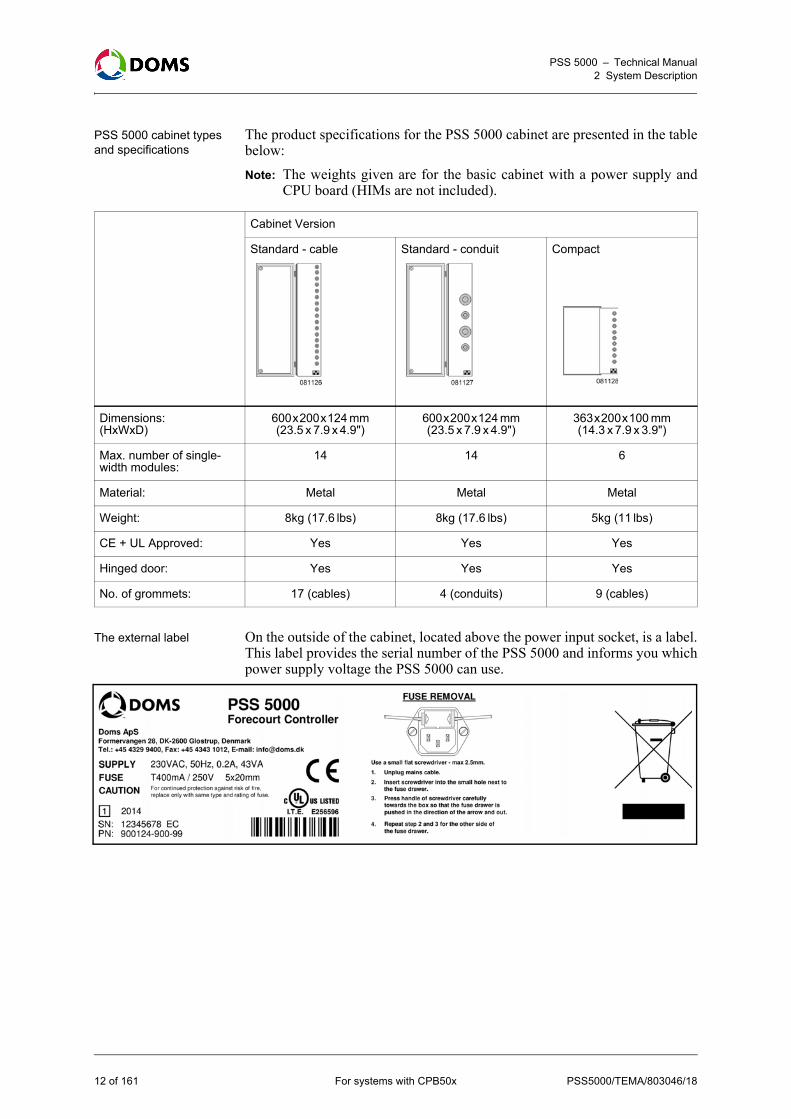
To view & verify the software installed on the PSS 5000
This procedure describes how to access the file system in a PSS 5000 using aWindows Explorer and an FTP connection.1. Using the standard Windows procedures, open the Windows Explorer.2. In the file path field, type in the following syntax.
FTP://admin:password@<IP address>
This syntax uses the default user name and password for the PSS 5000. Theillustration below shows how the IP address is entered.
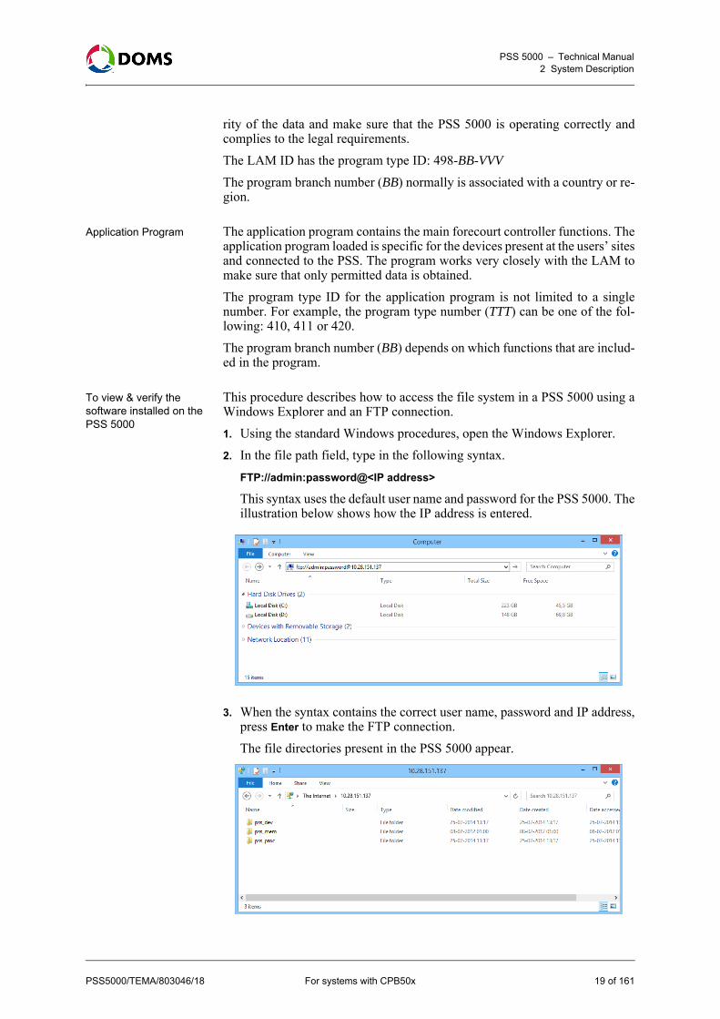
3. When the syntax contains the correct user name, password and IP address,press Enter to make the FTP connection.The file directories present in the PSS 5000 appear.
PSS5000/TEMA/803046/18 For systems with CPB50x 19 of 161

PSS 5000 – Technical Manual2 System Description
4. Using the standard Windows procedures, navigate to the following direc-tory: /pss_mem/1/prg
The binary files for the Application, LAM and Boot are stored here.
5. Copy the bin files to your computer.6. Using these files and a 3rd party hash calculator, you can verify that the
software present in the PSS 5000 has the correct MD5 hash code.
2.2.4 Web Server
Description of the web server
The embedded web server enables you to access the PSS 5000 Service Menususing a PC with a standard web browser.
Recommended browser versions
The embedded web server, which allows connection via standard browsers orspecific applications, has been tested with both Firefox and Microsoft brows-ers. Some of the features (for example the Peeper applet) require a MicrosoftInternet Explorer version 6.0 or higher, or Firefox version 1.5 or higher.
2.2.5 FTP Server
Description of the FTP server
The FTP server enables you to connect to the PSS 5000, see the internal filestructure and upload software applications. It also enables you to extract datalogs from remote locations.
Illustration of an FTP connection to file system in PSS 5000
This illustrates how to access the file system in a PSS 5000 using a web brows-er and an FTP connection. The FTP connection to the PSS 5000 is made bytyping FTP://admin:password@<IP address>.
Note: Other types of FTP client connections may be used. Use the same logon information with the FTP client of your choice.
20 of 161 For systems with CPB50x PSS5000/TEMA/803046/18

PSS 5000 – Technical Manual2 System Description
2.2.6 Serial Server
Description of the serial server
The PSS 5000 contains a serial server that enables communication overTCP/IP networks to pass-through the PSS 5000 and reach a device, such as atank gauge console, that is connected via a serial interface. This functionality is supported by several protocols, which are listed in theSoftware Release Document distributed with the PSS 5000 application.Note: For some older versions of the PSS 5000 Applications, special Protocol-
to-Port Assignment settings are required.
Port connection To communicate via the serial server a host must use the PSS 5000’s IP ad-dress + the TCP port number, which has the following format: 6000 + PSS portnumber.For example, if the device is connected to port 15, then the TCP port number= 6015.
2.2.7 Network Connection
Description of the network connection
For general access rights to devices on the network, please consult your net-work administrator. He will know which TCP/IP parameters you must use andwill configure the network (DHCP server, firewalls and the like). In this re-spect, the PSS 5000 is no different from any other network devices.
PSS5000/TEMA/803046/18 For systems with CPB50x 21 of 161

PSS 5000 – Technical Manual3 Configuration and Service
3 Configuration and Service
Overview Information about the configuration and service functions of the PSS 5000 aredescribed in the following topics:• ‘3.1 Configuration and Service Menus Access’ on page 22• ‘3.2 Software Changes’ on page 27
3.1 Configuration and Service Menus Access
Methods to access menus
There are 2 methods to access the service menus that enable you to configureand monitor the PSS 5000. Information about the access tools are described inthe following topics:• ‘3.1.1 Local Service Panel’ on page 22• ‘3.1.2 Web Service Pages’ on page 26
3.1.1 Local Service Panel
Purpose of the local service panel
The Local Service Panel allows you to access the PSS 5000 Service Menus.
The navigation buttons and the OK button, which allow you to navigatethrough the service menus, are located on the CPU Board beside the front pan-el. The function of each button is shown by an arrow or text label present onthe panel.
22 of 161 For systems with CPB50x PSS5000/TEMA/803046/18

PSS 5000 – Technical Manual3 Configuration and Service
Functions of the navigation buttons
In general, the navigation buttons are used as follows:
Functions of the CPU board LEDs
The CPU board has 2 LEDs associated with the Service Panel: BOOT and AP-PL. These LEDs are used to indicate the status of the program:
Buttons Description
These buttons are used in the following ways:
• To move down and up through the structure of the service menus. For example, to move from menu 1 to 2, or from menu 1.1 to 1.2.
• To move down and up through lines of data, where each line is a separate item. For example, a line is an individual transaction.
• To change the value of the parameter shown in the display.
These buttons are used in the following ways:
• To move to a lower or higher level of the current menu. For example, to move from menu 2 to 2.1.
• To move along a single line of data, for example in a transaction log.
• Left arrow only – to return to the Idle menu from a top level menu. For example, to move directly to Idle from menu 2.
This button is used to accept the value of a parameter after it has been changed.
BOOT LED APPL LED Description
Blink Off Boot running. Blink rate is according to the current load rate.
Off Blink Appl running. Blink rate according to the current load rate.
On Off Super Master Reset in progress. (Status of reset shown in display).
Off Very Fast Blink Master Reset in progress (APPL).
On Off Reset in progress. (No status informa-tion shown in display).
On On Erasing Flash (BOOT)
Alternating On Programming the Flash (APPL).
Off On APPL program stopped / Error State.
PSS5000/TEMA/803046/18 For systems with CPB50x 23 of 161

PSS 5000 – Technical Manual3 Configuration and Service
Display cycles during startup
The illustration below shows the Local Service Panel display messages andLEDs during the start up phase.
Local Service Panel display
The display in the Local Service Panel provides you with information aboutwhere you are in the menu structure, the software identification numbers, orthe current values of parameters selected in the software.
By default the Idle menu is displayed. The system returns to the Idle menu au-tomatically if a navigation button is not pressed within the timeout period. Thismenu shows the following information:• An 8 digit number, which is the ID of the Application software.• The current time of the PSS’s internal clock.• Arrows that inform you which button to press to enter the W&M or Ser-
vice menus. The Idle menu provides an entry point to both the W&M menus and the Servicemenus.
BOOT LED
APPL LED
StatusLSP Display
(Blank) BOOT started, call LAM module, initialize LAM.
BOOT initializes the file system, checks watch-dog & power.
Search for the Application; Start the Application.
(Blank) Application start up in progress.
Application fully initialized; forecourt running / ready.
Application initialized file system & start up.
If the display toggles here, this can indicate that the file system has been corrupted & the BOOT restarts continuously.
Idle menu(APPL version and time)
24 of 161 For systems with CPB50x PSS5000/TEMA/803046/18

PSS 5000 – Technical Manual3 Configuration and Service
Error messages on the service panel display
The display can show error codes or refer you to the error log file. If some ofthe errors are unread, then the lower line on the display tells you to look at thelog file.
The PSS 5000 has its own post-process, diagnostics program, which preventsthe program from running when serious errors occur. When this happens theprogram number and the text "DEAD" are displayed together with somecodes, as shown in the example below:
When this happens, write down this information and send it to Doms Supportat the following e-mail address: [email protected]
The "DEAD" text and error codes remain in the display until a button ispressed. This causes the CPU board to reset and attempt to re-start the appli-cation, or the CPU board is powered down.
Viewing data in the Local Service Panel display
Data stored in the PSS 5000 memory, such as Recent Transactions or Trans-action Log, can be viewed using the local service panel display. However, be-cause of the size of the display, it is important to understand how the data ap-pears and how it can be read. The figure below is an example of data in thememory and illustrates how much of it actually appears in the display.
In the figure above, you can see an example of the upload log. The rectanglewith the dotted line represents what you can actually see in the local servicedisplay panel. By using the navigation buttons, you are able to move the rect-angle so that other data appears in the display panel.
PSS5000/TEMA/803046/18 For systems with CPB50x 25 of 161

PSS 5000 – Technical Manual3 Configuration and Service
3.1.2 Web Service Pages
Web Service page start-up page
When accessing the Web Service pages a user_id and password is required.For more information about user IDs and passwords, see ‘5.4.1 Password(Menu 2.4.1)’ on page 52.
In addition to the navigation menu, the start up picture for the Web Servicepage displays some essential information, such as:• Site ID (Default value is the board serial number)• Application Software versionNote: The navigation system for the web page uses the same menu numbers
as the menu system on the local service panel.
To print a copy of the service menu page
This procedure describes how to print a copy of the current page displayed inthe Web Service Menu.Note: This procedure is for Internet Explorer. 1. Open the pop-up context menu in the frame of the page that you want to
print and select Print Preview....The Print Preview window appears.
2. In the tool bar:• Select Only the selected frame in the 2nd drop-down menu• Select Shrink to Fit in the 3rd drop-down menu• If necessary, use the orientation buttons to toggle between landscape
and portrait. Select the one that suits best.3. Press Alt+P (or print symbol in tool bar).
The Print window with your selected printer appears. If this is not the cor-rect printer, use standard Windows procedures to select the correct printer.
26 of 161 For systems with CPB50x PSS5000/TEMA/803046/18
PSS 5000 – Technical Manual3 Configuration and Service
4. Press Print.The selected frame prints.
3.2 Software Changes
Description of software changes
Changes to the Application Program and/or Legal Authority Module on thePSS 5000 board take place by uploading the software using the Web ServiceMenus (with a Java applet) or using an FTP connection. (FTP requires only afew commands). Note: Before attempting to upload an Application Program, please consult the
Software Release Document and check the requirements of the BOOTprogram and LAM.
When a Legal Authority Module is uploaded, the Application Program and alldata is cleared. When a new program (APPL or BOOT) is started, the PSS5000 automatically performs a reset. As the TCP/IP connection is lost duringa system reset, it is necessary to create a new connection in order to check theresult of the upload.
PSS5000/TEMA/803046/18 For systems with CPB50x 27 of 161

PSS 5000 – Technical Manual3 Configuration and Service
To change the software in the PSS 5000
This flow diagram shows the order in which software uploads must occurwhen changing the software in the PSS 5000.Note: Before software can be uploaded, the PSS 5000 must be set in a state
that allows the upload.
Upload log file All attempts to upload software to the PSS 5000 are recorded in the/pss_mem/1/sys/bul.txt file. This file cannot be erased and can be viewed usingthe web service pages, or downloaded using FTP and then viewed either withan FTP client or a simple text editor.
‘To upload software with the web service menus’ on page 61 or ‘To upload software using FTP’ on page 64
‘To upload software with the web service menus’ on page 61 or ‘To upload software using FTP’ on page 64
‘To upload software with the web service menus’ on page 61 or ‘To upload software using FTP’ on page 64
28 of 161 For systems with CPB50x PSS5000/TEMA/803046/18

PSS5000/TEMA/803046/18 For systems with CPB50x 29 of 161
PSS 5000 – Technical ManualPart Using the Service Menus
Part II: Using the Service MenusNote: The individual menu options available in the Service Menus depend on
the functions present in the program applications installed in the fore-court controller.
• ‘4 Information (Menu 1)’ on page 30
• ‘5 Installation (Menu 2)’ on page 36
• ‘6 Operation (Menu 3)’ on page 69
• ‘7 Reset (Menu 4)’ on page 81
• ‘8 Diagnostics (Menu 5)’ on page 85
• ‘9 W & M (Menu W)’ on page 114
PSS 5000 – Technical Manual4 Information (Menu 1)
4 Information (Menu 1)
Overview of Information menu
The Information menu is divided into the following sub-menus:• ‘4.1 Program Versions (Menu 1.1)’ on page 30• ‘4.2 Board Info (Menu 1.2)’ on page 31• ‘4.3 SW Blocks (Menu 1.3)’ on page 34• ‘4.4 Protocols (Menu 1.4)’ on page 35• ‘4.5 LAM (Menu 1.5)’ on page 35Note: For all Local Service Panel procedures, it is assumed that the Idle menu
(see ‘Local Service Panel display’ on page 24) is already shown in thedisplay.
4.1 Program Versions (Menu 1.1)
Description of the Program Versions menu
The Program Versions menu provides information about the version and re-lease date of the following programs:• Application Program• Boot Program• LAM (Legal Authority Module)If the program versions are not correct then it may be necessary to changethem. A description of how to do this is included in ‘3.2 Software Changes’ onpage 27.
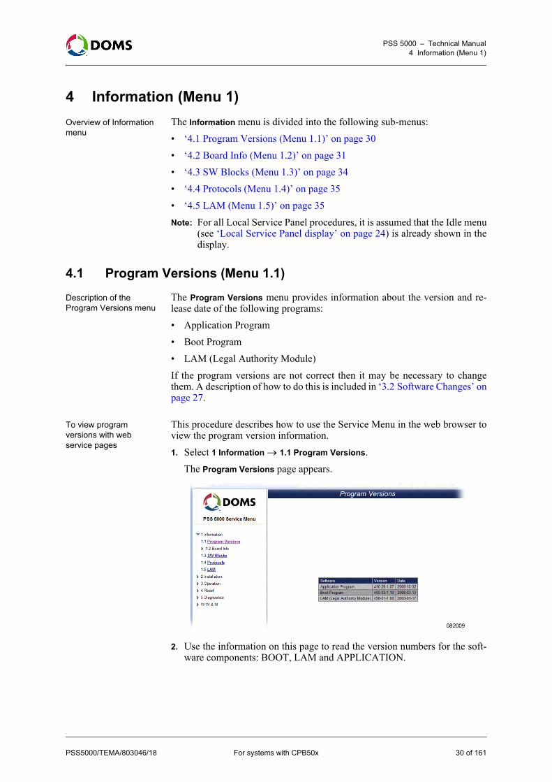
To view program versions with web service pages
This procedure describes how to use the Service Menu in the web browser toview the program version information. 1. Select 1 Information 1.1 Program Versions.
The Program Versions page appears.
2. Use the information on this page to read the version numbers for the soft-ware components: BOOT, LAM and APPLICATION.
PSS5000/TEMA/803046/18 For systems with CPB50x 30 of 161

PSS 5000 – Technical Manual4 Information (Menu 1)
To view program versions with local service panel
This procedure describes how to use the Local Service Panel to view the pro-gram version information for the software components: BOOT, LAM and AP-PLICATION.1. Press to move to the INFORMATION 1 menu.
2. Press to move to the PRG VERSION 1.1 menu.3. Press the buttons in the sequence shown below to move to the sub-menus
and view the program versions of the software components in the PSS5000.
View program versions using virtual file system
The program version information is also available in the following files usingthe PSS 5000 Virtual File System.• /pss_proc/sys/boot_inf.txt – contains BOOT information• /pss_proc/sys/lam_inf.txt – contains Legal Authority Module information• /pss_proc/sys/appl_inf.txt – contains Application information
4.2 Board Info (Menu 1.2)
Overview of Board Information
From the Board Info menu you can get both production information and sealingswitch status information. The menu is divided into the following sub-menus:• ‘4.2.1 Production (Menu 1.2.1)’ on page 31• ‘4.2.2 Sealing Switch (Menu 1.2.2)’ on page 33
4.2.1 Production (Menu 1.2.1)
Description of Production menu
The Production menu provides the following production information:• PCB layout• Engineering Change Status (ECS)• Serial Number• Production Number
PSS5000/TEMA/803046/18 For systems with CPB50x 31 of 161
PSS 5000 – Technical Manual4 Information (Menu 1)
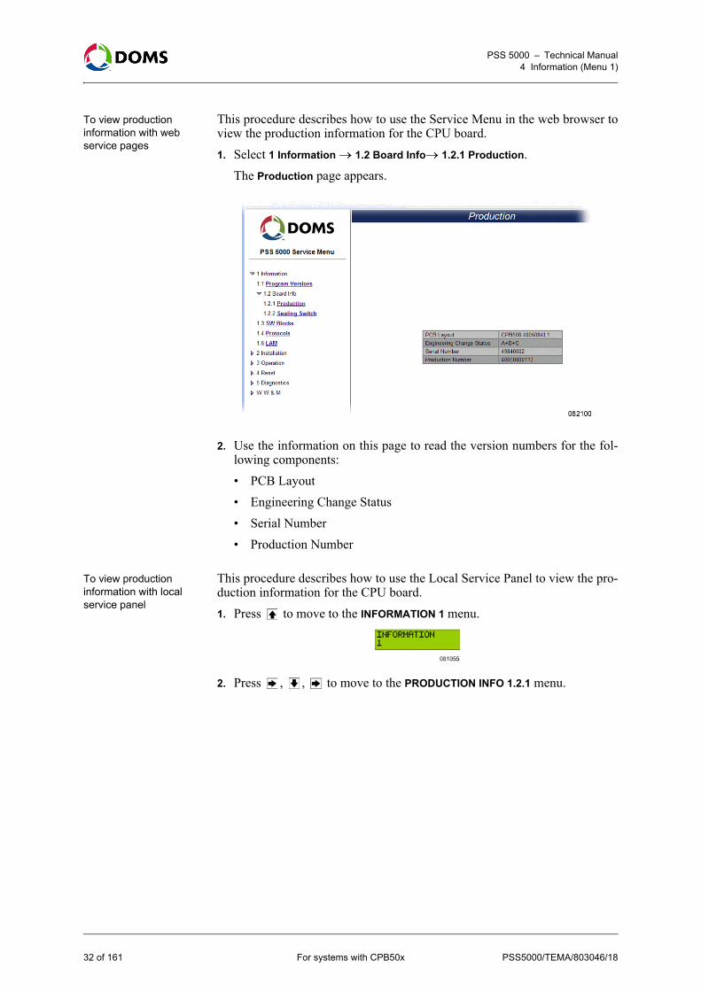
To view production information with web service pages
This procedure describes how to use the Service Menu in the web browser toview the production information for the CPU board. 1. Select 1 Information 1.2 Board Info1.2.1 Production.
The Production page appears.
2. Use the information on this page to read the version numbers for the fol-lowing components: • PCB Layout• Engineering Change Status• Serial Number• Production Number
To view production information with local service panel
This procedure describes how to use the Local Service Panel to view the pro-duction information for the CPU board.1. Press to move to the INFORMATION 1 menu.
2. Press , , to move to the PRODUCTION INFO 1.2.1 menu.
32 of 161 For systems with CPB50x PSS5000/TEMA/803046/18

PSS 5000 – Technical Manual4 Information (Menu 1)
3. Press the buttons in the sequence shown below to move to the sub-menusand view the production information for the PSS 5000.
The serial number and production number shown in the display are uniquefor the CPU Board of the PSS 5000 you are currently viewing.
4.2.2 Sealing Switch (Menu 1.2.2)
Description of Sealing Switch menu
The Sealing Switch menu provides information about the status of the sealingswitch, which is used to hardware seal the LAM software on the CPU board.
To view sealing switch status with web service pages
This procedure describes how to use the Service Menu in the web browser toview the status of the hardware sealing switch, which is used to enable LAMuploads. 1. Select 1 Information 1.2 Board Info1.2.2 Sealing Switch.
The Sealing Switch page appears.
2. Use the information on this page to see the status of the Hardware SealingSwitch.• OFF - no hardware sealing present on CPB• ON – hardware sealing present on CPB
PSS5000/TEMA/803046/18 For systems with CPB50x 33 of 161

PSS 5000 – Technical Manual4 Information (Menu 1)
To view sealing switch status with local service panel
This procedure describes how to use the Local Service Panel to view the statusof the hardware sealing switch.1. Press to move to the INFORMATION 1 menu.
2. Press , , , to move to the SEALING SWITCH 1.2.2 menu.3. Press to view the status of the sealing switch.
4.3 SW Blocks (Menu 1.3)
To view software blocks in PSS 5000 with web service pages
Each application program in the PSS 5000 is built from several software codeblocks. This procedure describes how to use the Service Menu in the webbrowser to view the SW blocks (names, ID, version and checksum). 1. Select 1 Information 1.3 SW Blocks.
The SW Blocks page appears.
2. Use the information on this page to see the Name, ID, Version number andChecksum for the individual software blocks.
34 of 161 For systems with CPB50x PSS5000/TEMA/803046/18

PSS 5000 – Technical Manual4 Information (Menu 1)
4.4 Protocols (Menu 1.4)
To view available protocols with web service pages
This procedure describes how to use the Service Menu in the web browser toview the protocols that are supported and can be assigned. 1. Select 1 Information 1.4 Protocols.
The Protocols page appears.
2. Use the information on this page to see a list of supported protocols.
4.5 LAM (Menu 1.5)
To view all the constants for the current LAM
This procedure describes how to use the Service Menu in the web browser toview all the constants set by the current LAM.1. Select 1 Information 1.5 LAM.
The LAM Information page appears.
2. Use the scroll bar to view all the constants, and their values, set by the cur-rent LAM.
PSS5000/TEMA/803046/18 For systems with CPB50x 35 of 161

PSS 5000 – Technical Manual5 Installation (Menu 2)
5 Installation (Menu 2)
Overview of Installation menu
The Installation menu is divided into the following sub-menus:• ‘5.1 Protocol to Port Assignment (Menu 2.1)’ on page 36• ‘5.2 Date and Time (Menu 2.2)’ on page 42• ‘5.3 Communication Setup (Menu 2.3)’ on page 43• ‘5.4 System Profile (Menu 2.4)’ on page 52• ‘5.5 Application Setup (Menu 2.5)’ on page 57• ‘5.6 Software Upload (Menu 2.6)’ on page 60• ‘5.7 Peripheral Configuration (Menu 2.7)’ on page 65• ‘5.8 Backup (Menu 2.8)’ on page 66
5.1 Protocol to Port Assignment (Menu 2.1)
Description of the protocol to port assignment menu
The PSS 5000 application can use a large number of protocols with which tocommunicate with the other system devices. Generally, the serial interface supports only one protocol per port. However,some protocol combinations are available and some protocols have mandatorysupplementary protocols. For example, when Doms POS Protocol is assignedon a serial interface port, then the Doms PSS Communication Protocol is as-signed automatically. When this occurs, multiple protocols are listed next tothe port number.Some protocols have additional protocol parameters. These parameter valuesare displayed in the Protocol column and can be set from the Protocol to PortAssignment window. To do this, see ‘5.1.2 Setting the Protocol ParameterValues’ on page 40.Some protocol to port assignments are restricted. For a description of these,see ‘5.1.3 Limitations’ on page 41.Note: Port 99 is a virtual port and does not physically present. Only certain
protocols can be assigned to use this port. These protocols are used forspecial purposes.
Protocol to port assignment overview
The details about the Protocol to Port Assignment window are included in thefollowing topics:• ‘5.1.1 Changing Protocol to Port Assignments’ on page 37• ‘5.1.2 Setting the Protocol Parameter Values’ on page 40• ‘5.1.3 Limitations’ on page 41
PSS5000/TEMA/803046/18 For systems with CPB50x 36 of 161

PSS 5000 – Technical Manual5 Installation (Menu 2)
5.1.1 Changing Protocol to Port Assignments
To configure protocol to port assignment with web service pages
This procedure describes how to use the Service Menu in the web browser toconfigure the protocol to port assignment values.1. Select 2 Installation 2.1 Protocol to Port Assignment.
The Protocol to Port Assignment page appears.
This page shows the protocols assigned to each of the ports on the CPUboard. Note: The Save Changes and Discard Changes buttons are only active after
changes have been made. Changes are indicated by a "*" next to theport number.
Note: Port 1 is labelled SERVICE PORT on the PSS 5000 panel.2. Do one of the following:
• View the port assignment details; no further action is required.• Add a protocol to port assignment (not Port 41 or 99); go to ‘To edit a
protocol to port assignment with web service pages’ on page 38• Add a new protocol to port assignment to Port 41 or 99: go to ‘To add a
protocol to Port 41 or Port 99 with web service pages’ on page 39• Set the parameters for a protocol; go to ‘To set protocol parameter val-
ues’ on page 40• Clear the protocols assigned to a specific port; go to ‘To remove a pro-
tocol to port assignment with web service pages’ on page 39.• Save all changes (including parameter values) made; go to Step 3.
PSS5000/TEMA/803046/18 For systems with CPB50x 37 of 161

PSS 5000 – Technical Manual5 Installation (Menu 2)
3. When all the changes have been made (i.e. protocols added / protocol pa-rameters set), click one of the following buttons:• Save Changes - saves and applies all changes to all ports; go to Step 4.• Discard Changes - cancels all changes made since the last save.• Factory Setting - restores all the Protocol to Port assignments to their
original values.4. In the confirmation window, click OK
The changes are saved and the PSS 5000 is Master Reset.
To edit a protocol to port assignment with web service pages
This procedure describes how to use the Service Menu in the web browser toedit a protocol to port assignment.Note: Do not use this procedure for Port 41 or Port 99.1. With the Protocol to Port Assignment window already open, go to the port
number that you want to change and click Edit. Note: If a protocol is already assigned to this port, it will be removed
during this procedure.The Edit Protocol to Port Assignment table for the selected port appears.The example below shows the table for Port 12.
2. Open the Protocol Type drop-down list and select the correct type of device.3. Open the Protocol drop-down list and select the correct protocol.4. If a protocol combination is possible, open the Protocol Combination drop-
down list and select the correct option.Note: A selection must be made here if there are 2 or more combinations.
5. Click OK.The page returns to the Protocol to Port Assignment list; go to ‘To configureprotocol to port assignment with web service pages’ on page 37, Step 2.Note: Changes are not activated until the Save Changes button in the Pro-
tocol to Port Assignment window is used and a Master Reset occurs.
38 of 161 For systems with CPB50x PSS5000/TEMA/803046/18

PSS 5000 – Technical Manual5 Installation (Menu 2)
To add a protocol to Port 41 or Port 99 with web service pages
This procedure describes how to use the Service Menu in the web browser toadd/change the protocol to port assignment values for Port 41 or Port 99. 1. With the Protocol to Port Assignment window already open, go to Port 41
or 99 and click Add. The Add a Protocol table for the port appears.The example below shows thetable for Port 41.
2. Open the Protocol Type drop-down list and select the correct type of device.3. Open the Protocol drop-down list and select the correct protocol.4. If a protocol combination is possible, open the Protocol Combination drop-
down list and select the correct option.Note: A selection must be made here if there are 2 or more combinations.
5. Click OK.The page returns to the Protocol to Port Assignment list; go to ‘To configureprotocol to port assignment with web service pages’ on page 37, Step 2.When the protocol has parameters, it may be necessary to set these beforethe Save Change button is used.
Note: Changes are not activated until the Save Changes button in the Protocolto Port Assignment window is used and a Master Reset occurs.
To remove a protocol to port assignment with web service pages
This procedure describes how to use the Service Menu in the web browser toremove a protocol to port assignment. 1. With the Protocol to Port Assignment window already open, go to the port
where you want to remove the protocol and click Clear (or Remove for Port41).
2. Do one of the following:• If you used Clear, the protocol is removed from the port list. Go to ‘To
configure protocol to port assignment with web service pages’ on page 37, Step 2.
• If you used Remove, the Remove a Protocol table appears; go to Step 3.3. Open the Protocol Type drop-down list and select the correct type of device.4. Open the Protocol drop-down list and select the correct protocol.5. If a protocol combination is used, open the Protocol Combination drop-
down list and select the correct option.Note: A selection must be made here if there are 2 or more combinations.
PSS5000/TEMA/803046/18 For systems with CPB50x 39 of 161

PSS 5000 – Technical Manual5 Installation (Menu 2)
6. Click OK.The page returns to the Protocol to Port Assignment list; go to ‘To configureprotocol to port assignment with web service pages’ on page 37, Step 2.Note: Changes are not activated until the changes are saved in Protocol to
Port Assignment window and the controller is Master Reset.
5.1.2 Setting the Protocol Parameter Values
To set protocol parameter values
This procedure describes how to set the parameters for protocols that use thesevalues.Note: This procedure uses a TCP/IP protocol to illustrate the steps.1. Select 2 Installation 2.1 Protocol to Port Assignment.
The Protocol to Port Assignment page appears.
2. Go to the port and protocol that you want to set and click Change.The Change Protocol Parameters table appears. The example below showsa tank gauge protocol that uses TCP/IP on Port 41.
3. Select the parameter fields and type in the correct values.Note: All values must also be aligned with the local parameters. For exam-
ple an IP address must match its local subnet.4. When all the values are correct, click OK.
40 of 161 For systems with CPB50x PSS5000/TEMA/803046/18

PSS 5000 – Technical Manual5 Installation (Menu 2)
Note: If you typed in a value that is outside the permitted range, a messageindicating the valid range appears. You must correct the value(s).
The Protocol to Port Assignment window appears.Note: The parameter changes are not applied until the next steps.
5. In the Protocol to Port Assignment window verify that all the values are cor-rect before you continue to the next step.
6. In the Protocol to Port Assignment window click Save Changes to apply thechanges.Note: If you do not wish to apply the changes, click Discard Changes.
7. In the confirmation window, click OK.The changes are saved and the PSS 5000 is Master Reset.
5.1.3 Limitations
List of areas with limitations
Not all protocol to port assignments are possible. There can be a number ofreasons why an assignment is not possible. The user interface, which is builtto prevent the user from making illegal assignments, reduces the selectable op-tions (reduced drop-down lists on the web service). Some of the limitations areexplained in the table below:Note: All TCP/IP protocols are fixed.
Protocols Explanation
Protocols regarding DMB Some protocols do not support addressable de-vices. To overcome this limitation a multiplexed port must be used.
IFSF protocols Generally, IFSF protocols run on PSS 5000 Port 31 (LON). However, some variants run on Port 41 (TCP/IP).
Single instance protocols Some protocols cannot be assigned to more than one port (for example, a log printer proto-col).
Special protocols Some protocols need special UART features. For example:
• Gilbarco pump (5787 baud)• Satam 008 pump (900 baud)• Scheidt & Bachmann T02 pump• MKS ER 3/2 pump
Due to PSS 5000 hardware limitations, it is not possible to run 2 of the protocols listed above on a PSS port pair that share UART hardware. The port pairs are:
• port 13 + 21• port 14 +22• port 15 +23
For example, if one of the protocols listed above is assigned to port 13, you will not be able to as-sign any of the protocols listed to port 21.
Point to Point PPP connections are only available on the DMB ports. And only one DMB port can be configured to use PPP.
PSS5000/TEMA/803046/18 For systems with CPB50x 41 of 161
PSS 5000 – Technical Manual5 Installation (Menu 2)
5.2 Date and Time (Menu 2.2)
Description of Date and Time menu
The PSS 5000 has it's own Real Time Clock (RTC), which is used to timestamp various events. The RTC setting can be changed via the Web, the LocalService Panel and in some applications via the POS Protocol.
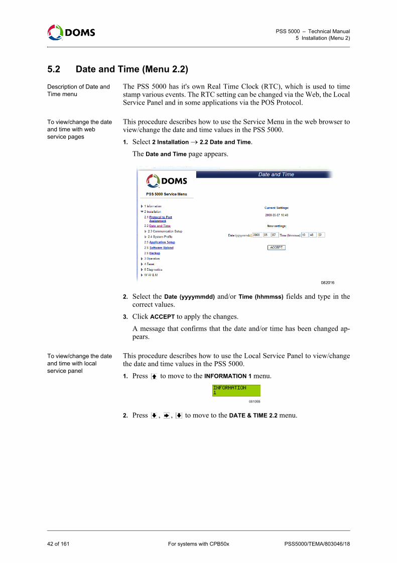
To view/change the date and time with web service pages
This procedure describes how to use the Service Menu in the web browser toview/change the date and time values in the PSS 5000. 1. Select 2 Installation 2.2 Date and Time.
The Date and Time page appears.
2. Select the Date (yyyymmdd) and/or Time (hhmmss) fields and type in thecorrect values.
3. Click ACCEPT to apply the changes.A message that confirms that the date and/or time has been changed ap-pears.
To view/change the date and time with local service panel
This procedure describes how to use the Local Service Panel to view/changethe date and time values in the PSS 5000.1. Press to move to the INFORMATION 1 menu.
2. Press , , to move to the DATE & TIME 2.2 menu.
42 of 161 For systems with CPB50x PSS5000/TEMA/803046/18

PSS 5000 – Technical Manual5 Installation (Menu 2)
3. Press the buttons in the sequence shown below to move to the sub-menusand view/change the date and time values in the PSS 5000.
5.3 Communication Setup (Menu 2.3)
Overview of Communication Setup menu
The Configuration Setup menu is divided in to the following sub-menus:• ‘5.3.1 TCP/IP Setup (Menu 2.3.1)’ on page 44• ‘5.3.2 Service Port Setup (Menu 2.3.2)’ on page 47• ‘5.3.3 Datalink Timeout for Serial Driver (Menu 2.3.3)’ on page 48• ‘5.3.4 Service Port Protocol (Menu 2.3.4)’ on page 49• ‘5.3.5 Menu 2.3.5 – Reserved for Future Use’ on page 50• ‘5.3.6 Dialup Setup/Test (Menu 2.3.6)’ on page 50• ‘5.3.7 Online/Offline Event Time (Menu 2.3.7)’ on page 51
PSS5000/TEMA/803046/18 For systems with CPB50x 43 of 161
PSS 5000 – Technical Manual5 Installation (Menu 2)
5.3.1 TCP/IP Setup (Menu 2.3.1)
Description of TCP/IP Setup menu
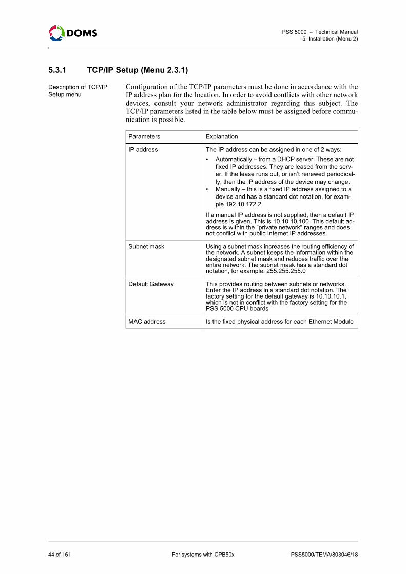
Configuration of the TCP/IP parameters must be done in accordance with theIP address plan for the location. In order to avoid conflicts with other networkdevices, consult your network administrator regarding this subject. TheTCP/IP parameters listed in the table below must be assigned before commu-nication is possible.
Parameters Explanation
IP address The IP address can be assigned in one of 2 ways:
• Automatically – from a DHCP server. These are not fixed IP addresses. They are leased from the serv-er. If the lease runs out, or isn’t renewed periodical-ly, then the IP address of the device may change.
• Manually – this is a fixed IP address assigned to a device and has a standard dot notation, for exam-ple 192.10.172.2.
If a manual IP address is not supplied, then a default IP address is given. This is 10.10.10.100. This default ad-dress is within the "private network" ranges and does not conflict with public Internet IP addresses.
Subnet mask Using a subnet mask increases the routing efficiency of the network. A subnet keeps the information within the designated subnet mask and reduces traffic over the entire network. The subnet mask has a standard dot notation, for example: 255.255.255.0
Default Gateway This provides routing between subnets or networks. Enter the IP address in a standard dot notation. The factory setting for the default gateway is 10.10.10.1, which is not in conflict with the factory setting for the PSS 5000 CPU boards
MAC address Is the fixed physical address for each Ethernet Module
44 of 161 For systems with CPB50x PSS5000/TEMA/803046/18

PSS 5000 – Technical Manual5 Installation (Menu 2)
To view/change the TCP/IP setup with web service pages
This procedure describes how to use the Service Menu in the web browser toview/change the values for the TCP/IP setup parameters in the PSS 5000. 1. Select 2 Installation 2.3 Communication Setup 2.3.1 TCP/IP Setup.
The TCP/IP Setup page appears.
2. Do one of the following:• Select Obtain IP address automatically (using DHCP), go to Step 4.• Select Specify an IP address, go to Step 3.
3. Use the correct naming conventions and notation to type in the requiredvalues for:• IP Address
• Subnet Mask
• Default Gateway
4. In the MAC Address: field, view the MAC address for the Ethernet module.5. Click ACCEPT to apply the changes.After the IP address has been changed, it is necessary to reconnect to the PSS5000 using the new IP address.
To view/change the TCP/IP setup with local service panel
This procedure describes how to use the Local Service Panel to view/changethe values of the TCP/IP setup parameters in the PSS 5000.1. Press to move to the INFORMATION 1 menu.
2. Press , , , , to move to the TCP/IP SETUP 2.3.1 menu.
PSS5000/TEMA/803046/18 For systems with CPB50x 45 of 161

PSS 5000 – Technical Manual5 Installation (Menu 2)
3. Press the buttons in the sequence shown below to move to the sub-menusand view/change the IP address in the PSS 5000.
Note: The current DHCP setting is flashing.4. In the Use DHCP? sub-menu, use the and buttons to toggle between
NO and YES.5. Press OK to save the change.• If you selected USE DHCP? YES, go to Step 8.• If you selected USE DHCP? NO, go to Step 6.6. Press to move to the SET IP ADDRESS sub-menu.7. Use the and buttons change the value that is flashing. Use and
to move forward to the next or backwards to the previous values, re-spectively.
8. Press OK when the NEW SETUP RESET NOW sub-menu appears.The changes to the parameter values are implemented.
To view the MAC address of the Ethernet module with local service panel
This procedure describes how to use the Local Service Panel to view the MACaddress of the Ethernet module in the PSS 5000.1. Press to move to the INFORMATION 1 menu.
2. Press , , , , to move to the TCP/IP SETUP 2.3.1 menu.3. Press the buttons in the sequence shown below to move to the sub-menus
and view the MAC address of the Ethernet module in the PSS 5000.
46 of 161 For systems with CPB50x PSS5000/TEMA/803046/18

PSS 5000 – Technical Manual5 Installation (Menu 2)
5.3.2 Service Port Setup (Menu 2.3.2)
Description of service port setup
The Service Port Setup menu enables you to set up the communication param-eters for the Service Port present on the CPU board. The Service Port is a serialinterface port, and the following parameters must be defined:
Note: The values underlined are the default values.
To view/change the Service Port setup with web service pages
This procedure describes how to use the Service Menu in the web browser toview/change the values for the Service Port Setup in the PSS 5000. 1. Select 2 Installation 2.3 Communication Setup 2.3.2 Service Port Setup.
The Service Port Setup page appears.
2. Select the Baud rate value that matches your system.3. Select the PPP device value that matches your system.
Note: If Modem is selected, it is necessary to set up the external modem tocommunicate with the port. In addition to this, the Service port isonly able to receive calls, therefore it is not possible to dial out usingthis port.
4. Click ACCEPT to apply the changes.
To view/change the Service Port Setup with local service panel
This procedure describes how to use the Local Service Panel to view/changethe values of the Service Port Setup in the PSS 5000.
Parameter Values
Baud rate 900, 19200, 38400, 57600, 115200
PPP device modem, NULL modem
PSS5000/TEMA/803046/18 For systems with CPB50x 47 of 161

PSS 5000 – Technical Manual5 Installation (Menu 2)
1. Press to move to the INFORMATION 1 menu.
2. Press , , , , , to move to the SVCPORT SETUP 2.3.2 menu.3. Press the buttons in the sequence shown below to move to the sub-menus
and view/change the baud rate and the PPP device values in the PSS 5000.
Note: The current setting is flashing in each of the sub-menus.4. Use the and buttons to change the value of the current setting, which
is flashing.5. To change the settings in the other sub-menus, repeat steps 3. and 4.6. Press OK.
The NEW SETUP RESET NOW sub-menu appears 7. Press OK to apply the changes to the parameters.
5.3.3 Datalink Timeout for Serial Driver (Menu 2.3.3)
To view/change the Datalink Timeout with web service pages
This procedure describes how to use the Service Menu in the web browser toview/change the values for the Datalink Timeout of the serial driver in the PSS5000. 1. Select 2 Installation 2.3 Communication Setup 2.3.3 Datalink Timeout.
The Datalink Timeout page appears.
48 of 161 For systems with CPB50x PSS5000/TEMA/803046/18
PSS 5000 – Technical Manual5 Installation (Menu 2)
2. In the Enter new datalink timeout: field type in the new value (in millisec-onds) for the timeout.Note: The permitted range is: 50, 51, 52, ..., 998, 999, 1000
3. Click ACCEPT to save the changes.The new value is effective after the board is reset.
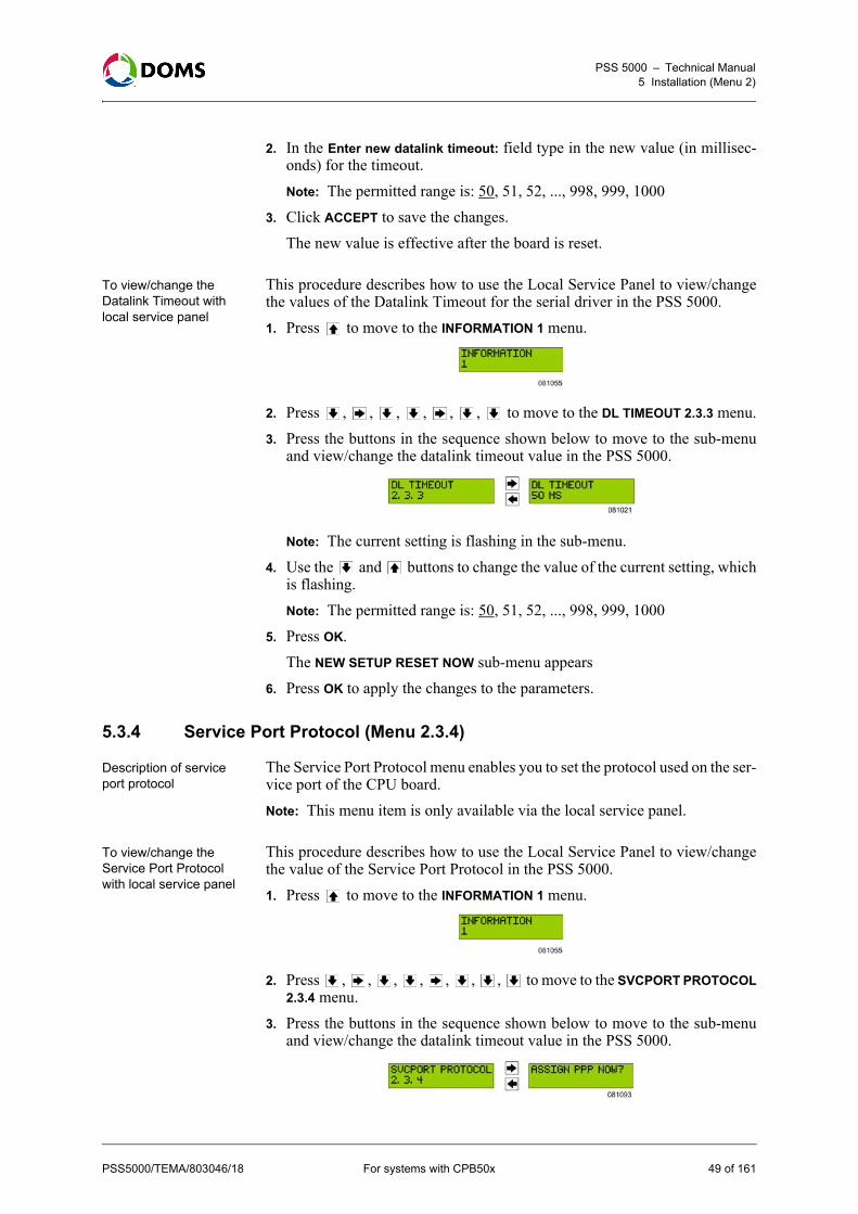
To view/change the Datalink Timeout with local service panel
This procedure describes how to use the Local Service Panel to view/changethe values of the Datalink Timeout for the serial driver in the PSS 5000.1. Press to move to the INFORMATION 1 menu.
2. Press , , , , , , to move to the DL TIMEOUT 2.3.3 menu.3. Press the buttons in the sequence shown below to move to the sub-menu
and view/change the datalink timeout value in the PSS 5000.
Note: The current setting is flashing in the sub-menu.4. Use the and buttons to change the value of the current setting, which
is flashing.Note: The permitted range is: 50, 51, 52, ..., 998, 999, 1000
5. Press OK.The NEW SETUP RESET NOW sub-menu appears
6. Press OK to apply the changes to the parameters.
5.3.4 Service Port Protocol (Menu 2.3.4)
Description of service port protocol
The Service Port Protocol menu enables you to set the protocol used on the ser-vice port of the CPU board.Note: This menu item is only available via the local service panel.
To view/change the Service Port Protocol with local service panel
This procedure describes how to use the Local Service Panel to view/changethe value of the Service Port Protocol in the PSS 5000.1. Press to move to the INFORMATION 1 menu.
2. Press , , , , , , , to move to the SVCPORT PROTOCOL2.3.4 menu.
3. Press the buttons in the sequence shown below to move to the sub-menuand view/change the datalink timeout value in the PSS 5000.
PSS5000/TEMA/803046/18 For systems with CPB50x 49 of 161

PSS 5000 – Technical Manual5 Installation (Menu 2)
4. Press OK to assign the named protocol.The NEW SETUP RESET NOW sub-menu appears
5. Press OK to apply the changes to the parameters.
5.3.5 Menu 2.3.5 – Reserved for Future Use
Reserved This menu item is reserved for future use.
5.3.6 Dialup Setup/Test (Menu 2.3.6)
Description of Dialup Setup/Test
The Dialup Setup/Test menu enables you to set up the communication param-eters for a modem connected to one of the DMB ports in the PSS 5000. Beforethe dialup connection can work, the following parameters must be defined:
To view/change Dialup Setup/Test with web service pages
This procedure describes how to use the Service Menu in the web browser toview/change the values for the dialup settings in the PSS 5000.Note: Before these settings are valid, one of the DMB ports in the PSS 5000
must be configured to use the Point to Point Protocol (PPP). See‘5.1 Protocol to Port Assignment (Menu 2.1)’ on page 36.
Parameter Values
Baud rate 900, 19200, 38400, 57600, 115200
PPP device modem, NULL modem
Modem init string* Standard AT commands required to initialize modem. String = max. 64 characters
Modem dial string* Telephone number for outgoing calls. String = max. 32 characters.
User name* Log on user name required by destination. Maximum of 20 characters allowed.
Password* Log on password required for user name at destination. Maximum of 20 characters allowed.
*: These parameters are only required when it is necessary to dial out from the PSS 5000. They are not required when null-modem is selected.
50 of 161 For systems with CPB50x PSS5000/TEMA/803046/18

PSS 5000 – Technical Manual5 Installation (Menu 2)
1. Select 2 Installation 2.3 Communication Setup 2.3.6 Dialup Setup/Test.The Dialup Settings page appears.
2. Select the Baud rate value that matches your system.3. Select the PPP device value that matches your system.4. In the Modem init string: field, type in a string of text that initiates the mo-
dem. 5. In the Modem dial string: field, type in the telephone number that you want
to dial. 6. In the User name: field, type in the user name you want to use to access the
PSS 5000. 7. In the Password: field, type in the correct password for the given user
name. 8. Click Save and Dialup.
The new dialup settings are saved, and the modem tests them by connectingto the destination number.
5.3.7 Online/Offline Event Time (Menu 2.3.7)
Description of Online/Offline Event Timer
The online/offline event timer is a filter, which reduces the number of on-line/offline events displayed. Only those online/offline events that exceed thetime period (specified in the Online/Offline Event Timer page) are displayed.
PSS5000/TEMA/803046/18 For systems with CPB50x 51 of 161
PSS 5000 – Technical Manual5 Installation (Menu 2)
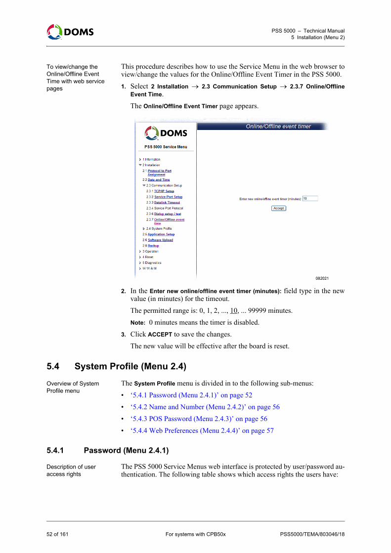
To view/change the Online/Offline Event Time with web service pages
This procedure describes how to use the Service Menu in the web browser toview/change the values for the Online/Offline Event Timer in the PSS 5000. 1. Select 2 Installation 2.3 Communication Setup 2.3.7 Online/Offline
Event Time.The Online/Offline Event Timer page appears.
2. In the Enter new online/offline event timer (minutes): field type in the newvalue (in minutes) for the timeout. The permitted range is: 0, 1, 2, ..., 10, ... 99999 minutes. Note: 0 minutes means the timer is disabled.
3. Click ACCEPT to save the changes.The new value will be effective after the board is reset.
5.4 System Profile (Menu 2.4)
Overview of System Profile menu
The System Profile menu is divided in to the following sub-menus:• ‘5.4.1 Password (Menu 2.4.1)’ on page 52• ‘5.4.2 Name and Number (Menu 2.4.2)’ on page 56• ‘5.4.3 POS Password (Menu 2.4.3)’ on page 56• ‘5.4.4 Web Preferences (Menu 2.4.4)’ on page 57
5.4.1 Password (Menu 2.4.1)
Description of user access rights
The PSS 5000 Service Menus web interface is protected by user/password au-thentication. The following table shows which access rights the users have:
52 of 161 For systems with CPB50x PSS5000/TEMA/803046/18

PSS 5000 – Technical Manual5 Installation (Menu 2)
Note: When a Super Master Reset takes place on the PSS 5000, all the pass-words are reset to their default settings.
Passwords can only be changed by the admin user, and all fixed passwordsmust have 3 – 16 characters. Passwords may consist of lower case letters, up-per case letters and digits only.On a clean CPU board without any LAM, only the admin user is accepted.All users can also have a dynamic password of the day. This can be obtainedfrom the system administrator.Note: 3 incorrect password attempts will block access for one minute. Hereaf-
ter, only one attempt is accepted per minute until a successfully log onwith a correct password is achieved.
To change the user password with web service pages
This procedure describes how to use the Service Menu in the web browser tochange the user password for the PSS 5000. Note: This procedure describes what is available when an admin user is logged
on.
User Description
admin This is used by the PSS system administrator and has all privileges:
• Read everything• Change all settings• Perform Reset, Master Reset and Super Master
Reset• Upload software• Change passwords for other users
host This is used by host applications (e.g. Doms Site Info) to access the PSS 5000 (read & write) via Doms Host Protocol.
service This provides the privileges needed by service techni-cians:
• Read everything• Start embedded peeper to create traces• Perform Reset, Master Reset and Super Master
Reset
manager This provides Read only access to all information and access to change Prices.
guest This provides Read only access to all information.
vrc This is used by Vapor Recovery System administra-tors. This user name is only supported in applications, where Vapor Recovery Controller functionality runs on the PSS 5000.
POS This is used by POS applications via the Doms POS Protocol. POS users are able to lock and clear transac-tions.
PSS5000/TEMA/803046/18 For systems with CPB50x 53 of 161

PSS 5000 – Technical Manual5 Installation (Menu 2)
1. Select 2 Installation 2.4 System Profile 2.4.1 Password.The Change Password page appears.
2. Open the Select user drop-down list and select the user that needs the pass-word changed.When you select a user, the following fields become active:• Enter old password: – this field is only active when the admin user is
changing the admin password.• Enter new password:
• Enter new password again:
3. For the admin password only – in the Enter old password: field type in thecurrent password for the selected user.
4. In the Enter new password: field type in the new password for the user.Note: The password must have 3 – 16 characters and must not contain any
special characters.5. In the Enter new password again: field, re-type the password given in Step
4.6. Click OK to save the changes.
A message appears which confirms that the password was changed andtells you to log off and reconnect to the PSS 5000.
54 of 161 For systems with CPB50x PSS5000/TEMA/803046/18

PSS 5000 – Technical Manual5 Installation (Menu 2)
Emergency access to the PSS 5000
In case passwords are forgotten it is possible to gain access in two differentways:• ‘To use Doms password for a day’ on page 55• ‘To use the default user password with local service panel’ on page 55These methods make it possible to restore the fixed passwords to the wantedvalues, or to give temporary system access to a person on the site.
To use Doms password for a day
The doms user has the same privileges as the admin user but uses a special dy-namic "Doms password of the day". This password has 4 HEX characters (0–9, A–F) and can be obtained by contacting Doms Support. The PSS 5000 has a password validation routine in the Legal Authority Mod-ule with fixed user_id/password combinations. The default password for allusers is "password".
To use the default user password with local service panel
All original user default passwords (password) can be re-enabled temporarilyfrom the Local Service Panel. This enables a technician, who has access to anopen box, to always get access to the system. Protection of the physical accessto the room or the box itself is outside the scope of this documentation. Thebox can be behind a locked door or the box can be locked. The default pass-words will be active until disabled manually again from the Local Service Pan-el or until the end of the current day. This procedure describes how to use theLocal Service Panel to select the default user password of the PSS 5000.1. Press to move to the INFORMATION 1 menu.
2. Press , , , , , to move to the DEFAULT PASSWORD 2.4.1menu.
3. Press to move to the ENABLE D.PASSW? menu.
4. Use the and buttons to toggle between YES and NO.5. Select YES and press OK to make the changes.
PSS5000/TEMA/803046/18 For systems with CPB50x 55 of 161
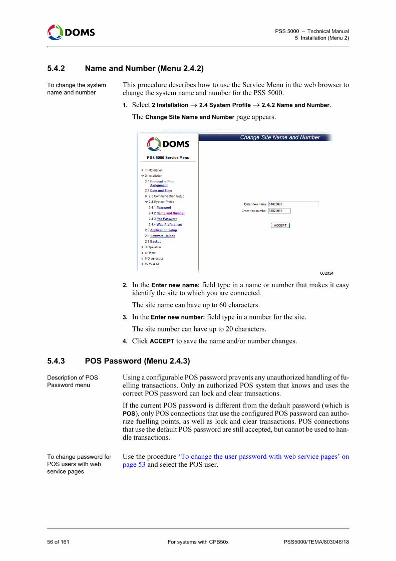
PSS 5000 – Technical Manual5 Installation (Menu 2)
5.4.2 Name and Number (Menu 2.4.2)
To change the system name and number
This procedure describes how to use the Service Menu in the web browser tochange the system name and number for the PSS 5000.1. Select 2 Installation 2.4 System Profile 2.4.2 Name and Number.
The Change Site Name and Number page appears.
2. In the Enter new name: field type in a name or number that makes it easyidentify the site to which you are connected.The site name can have up to 60 characters.
3. In the Enter new number: field type in a number for the site.The site number can have up to 20 characters.
4. Click ACCEPT to save the name and/or number changes.
5.4.3 POS Password (Menu 2.4.3)
Description of POS Password menu
Using a configurable POS password prevents any unauthorized handling of fu-elling transactions. Only an authorized POS system that knows and uses thecorrect POS password can lock and clear transactions.If the current POS password is different from the default password (which isPOS), only POS connections that use the configured POS password can autho-rize fuelling points, as well as lock and clear transactions. POS connectionsthat use the default POS password are still accepted, but cannot be used to han-dle transactions.
To change password for POS users with web service pages
Use the procedure ‘To change the user password with web service pages’ onpage 53 and select the POS user.
56 of 161 For systems with CPB50x PSS5000/TEMA/803046/18

PSS 5000 – Technical Manual5 Installation (Menu 2)
5.4.4 Web Preferences (Menu 2.4.4)
Description of web preferences
This menu enables you to make some minor changes to the appearance of theweb pages. You can include your own logo or graphic in the top left-hand cor-ner of the service menu pages, and you can change the rate by which informa-tion in the Operational Status web pages is updated from the PSS 5000.
To change the web preferences
This procedure describes how to use the Service Menu in the web browser tochange the appearance of the web pages and the rate by which information isupdated from the PSS 5000.1. Select 2 Installation 2.4 System Profile 2.4.4 Web Preferences.
The Web Preferences page appears.
2. To insert a logo/graphic in the top left-hand corner of the web page, clickBrowse in the Custom Logo group.The Choose file window appears.
3. In the Choose file window, locate the graphic file you want to include in theweb page.
4. Click Open to include the path to the graphic file in the field next to theBrowse button.
5. Do one of the following:• If you want to change the refresh rate parameters, go to Step 6.• If you want to include the new logo/graphic now, go to Step 7.
6. In the Parameters group, type in the new refresh rate (in seconds).7. Click OK to save and implement the changes.
5.5 Application Setup (Menu 2.5)
To set/change the application setup
During installation, various application dependent functions might be config-urable using the Application Setup menu – the specific applications determinewhat is actually configurable.
PSS5000/TEMA/803046/18 For systems with CPB50x 57 of 161

PSS 5000 – Technical Manual5 Installation (Menu 2)
1. Select 2 Installation 2.5 Application Software.The Application Setup page appears.
2. In the Select Setup Group table, open the Setup Group? drop-down list.3. Select one of the following:
• Forecourt Control Setup. To continue go to ‘To set/change the Fore-court Control Setup’ on page 58.
• Protocol Specific Setup. To continue go to ‘To set/change the Protocol Specific Setup’ on page 59.
When you have completed the steps in the procedures above you will be re-turned to the PSS 5000 Service Menus.
To set/change the Forecourt Control Setup
Use this procedure when you have selected the Forecourt Control Setup optionin the Application Setup menu.1. In the Forecourt Application drop-down list, select one of the following:
• PSS License Management, go to Step 2.• Wet Stock Setup, go to Step 4.• Totals Setup, go to Step 6.• Local Service Panel Setup, go to Step 7.
2. In the PSS License Management page, type the License Key for the selectedapplication.
3. Click Submit key.To continue using the PSS 5000 Service Menus, select a new menu option.
58 of 161 For systems with CPB50x PSS5000/TEMA/803046/18

PSS 5000 – Technical Manual5 Installation (Menu 2)
4. In the Wet Stock Setup page, select the required New Setup radio button.
Note: On should be selected if delivery information is required but the sys-tem does not contain a POS that is capable of clearing the deliveryreport.
5. Click one of the following.• Save
• Recall default settings
• Prev. Menu
To continue using the PSS 5000 Service Menus, select a new menu option.6. In the Totals Setup page, use the Clear totals at master reset option to spec-
ify if totals must be retained or removed during a PSS Master Reset:
• Select the check box to clear totals during a PSS Master Reset (default setting).
• Clear the check box to keep totals after a PSS Master Reset. 7. In the Local Service Panel (LSP) Setup page, use the Allow Local Service
Panel (LSP) setup check box to allow/prevent changes being made to thefollowing parameters via the LSP.• Date & Time (Real Time clock)• Prices (in selected Applications)
By default the check box is selected.8. Click Save.
To continue using the PSS 5000 Service Menus, select a new menu option.
To set/change the Protocol Specific Setup
Use this procedure when you have selected the Protocol Specific Setup optionin the Application Setup menu.
PSS5000/TEMA/803046/18 For systems with CPB50x 59 of 161

PSS 5000 – Technical Manual5 Installation (Menu 2)
1. In the Protocol? drop-down list, select the protocol that is to be configured.2. In the page that appears, type in the specific configuration parameters and
click OK.3. Select a menu option to continue using the PSS 5000 Service Menu.
5.6 Software Upload (Menu 2.6)
Description of the Software Upload menu
Software upload is done by uploading a file via FTP and/or by using the Webinterface (PSS program dependent). An upload will clear the old program from the system, so normal operation isinterrupted during a program change. A program change automatically resultsin a Master Reset of the system. Software uploads can be performed from aremote location, but not before someone has set the system in a mode where itis permitted to load software.Setting the PSS 5000 to accept software uploads is enabled using either theweb service pages or the local service panel.
Software upload methods
Several methods to upload software are available:
Interface Description
Old web service menus Software upload followed by an FTP upload program session.
New web service menus Software upload followed by an FTP upload program session.
Software upload followed by a Web applet based up-load program session.
Local service panel Software upload followed by an FTP upload program session.
FTP Software upload by uploading file ok2load.txt followed by an FTP program upload session.
60 of 161 For systems with CPB50x PSS5000/TEMA/803046/18
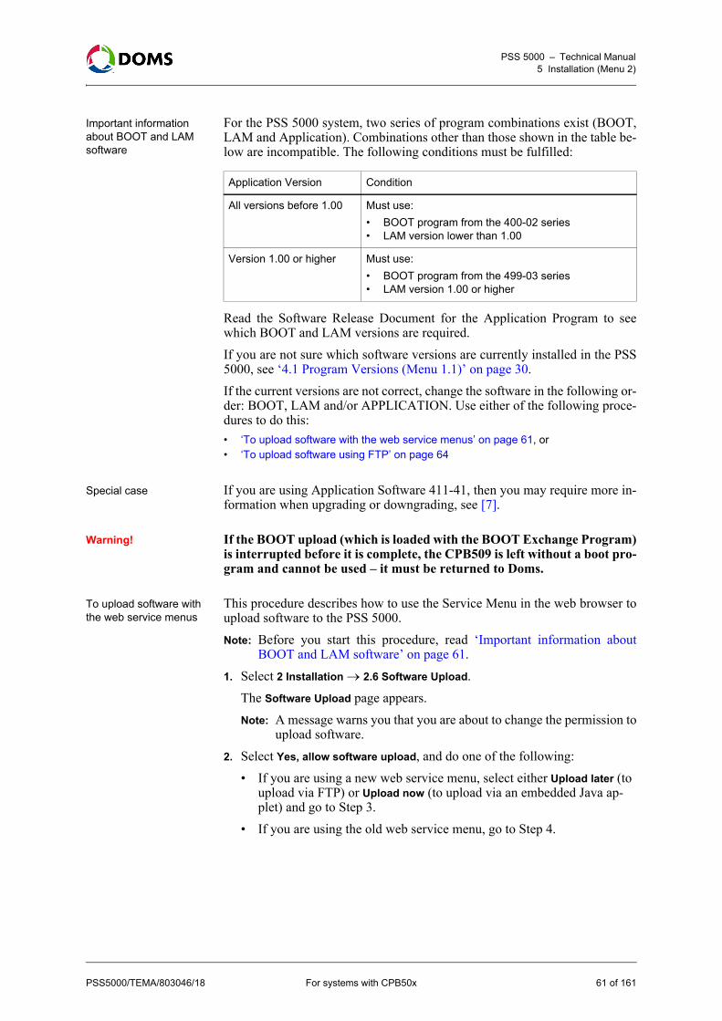
PSS 5000 – Technical Manual5 Installation (Menu 2)
Important information about BOOT and LAM software
For the PSS 5000 system, two series of program combinations exist (BOOT,LAM and Application). Combinations other than those shown in the table be-low are incompatible. The following conditions must be fulfilled:
Read the Software Release Document for the Application Program to seewhich BOOT and LAM versions are required. If you are not sure which software versions are currently installed in the PSS5000, see ‘4.1 Program Versions (Menu 1.1)’ on page 30. If the current versions are not correct, change the software in the following or-der: BOOT, LAM and/or APPLICATION. Use either of the following proce-dures to do this:• ‘To upload software with the web service menus’ on page 61, or • ‘To upload software using FTP’ on page 64
Special case If you are using Application Software 411-41, then you may require more in-formation when upgrading or downgrading, see [7].
Warning! If the BOOT upload (which is loaded with the BOOT Exchange Program)is interrupted before it is complete, the CPB509 is left without a boot pro-gram and cannot be used – it must be returned to Doms.
To upload software with the web service menus
This procedure describes how to use the Service Menu in the web browser toupload software to the PSS 5000.Note: Before you start this procedure, read ‘Important information about
BOOT and LAM software’ on page 61.1. Select 2 Installation 2.6 Software Upload.
The Software Upload page appears.Note: A message warns you that you are about to change the permission to
upload software. 2. Select Yes, allow software upload, and do one of the following:
• If you are using a new web service menu, select either Upload later (to upload via FTP) or Upload now (to upload via an embedded Java ap-plet) and go to Step 3.
• If you are using the old web service menu, go to Step 4.
Application Version Condition
All versions before 1.00 Must use:
• BOOT program from the 400-02 series• LAM version lower than 1.00
Version 1.00 or higher Must use:
• BOOT program from the 499-03 series• LAM version 1.00 or higher
PSS5000/TEMA/803046/18 For systems with CPB50x 61 of 161

PSS 5000 – Technical Manual5 Installation (Menu 2)
3. Do one of the following:• If you selected Upload later or Upload now in Step 2, open the Upload
Start Timeout drop-down list and select the timer value. The upload must be started within the time selected or an upload timeout occurs. Possible timeout values are: 3 minutes, 30 minutes, 3 hours, 8 hours and 24 hours.
• If you are using the old web service menu, continue to the next step.4. Click Accept.
• If you are using an old web service menu or you selected Upload later, then a message appears that tells you that the upload is possible until the time shown.
Use a standard FTP procedure to upload the software file, see ‘To up-load software using FTP’ on page 64, and go to Step 7.
• If you selected Upload now, a new page appears that tells you that you are about to upload software.Note: Depending on the Java version installed, you may be required to
log in again
62 of 161 For systems with CPB50x PSS5000/TEMA/803046/18

PSS 5000 – Technical Manual5 Installation (Menu 2)
5. Type in the correct information for the following fields:• User name – PSS 5000 user name• Password – password for PSS 5000 user name• Log text – additional text to help identify the upload• Files – location and file name of software you want to upload• Backup PSS – (optional) specify a location for the backup of the cur-
rent LAM and Application files6. Click Upload.
Caution: Do not close the web page until after the upload is finished. If theJava applet is closed, then it may be necessary to upload usingFTP.
A status of the software upload appears in the information field. When theupload is finished, this is shown in the status information.
7. To verify that the software was uploaded correctly, use the Program Ver-sions menu.
To allow software uploads with local service panel
This procedure describes how to allow software to be uploaded to the PSS5000 using the local service panel.Note: Before you start this procedure, read ‘Important information about
BOOT and LAM software’ on page 61.1. Press to move to the INFORMATION 1 menu.
2. Press , , , , , , to move to the SOFTWARE UPLOAD 2.6menu.
3. Press to move to the ALLOW UPLOAD? menu.
4. Use and to toggle between YES and NO.When the Allow upload value is YES, then it is possible to upload softwareusing FTP, see ‘To upload software using FTP’ on page 64.Note: If you change the Allow upload value to YES, then you must reset the
PSS 5000 before the software upload can start.5. Press .
The following file is created: /pss_mem/2/sys/ok2upload.txt. This file mustbe present before FTP can be used to upload software. See ‘To upload soft-ware using FTP’ on page 64.Note: There is a time limit on the presence of the ok2upload.txt file. If too
much time passes, an upload timeout occurs and the file is deleted.It is necessary to repeat the procedure that allows the upload and cre-ates the file.
PSS5000/TEMA/803046/18 For systems with CPB50x 63 of 161

PSS 5000 – Technical Manual5 Installation (Menu 2)
To upload software using FTP
This procedure describes how to use FTP to upload software to the PSS 5000.The commands used in this procedure use FileZilla to illustrate the commands.However, other FTP clients may be used.Note: When Application files are uploaded, the PSS erases the existing file.
As this takes time, it is necessary to set the FTP client’s Transfer Tim-eout setting to 180 seconds.
Note: Before you start to upload software with FTP, you must make the PSS5000 ready to accept the software. To do this see ‘To upload softwarewith the web service menus’ on page 61, or ‘To allow software uploadswith local service panel’ on page 63.
1. Start the FTP client.2. Check/change the transfer timeout settings. The timeout must be set to
180 seconds.
Failure to verify this setting may result in the software upload not beingsuccessful.
3. Use the web Service Menu 2.6 Software Upload to verify that the PSS isready to accept the software. The following dialog must appear:
If this dialog does not appear, use menu 4.1 Soft Reset to reboot the PSSnow.
64 of 161 For systems with CPB50x PSS5000/TEMA/803046/18

PSS 5000 – Technical Manual5 Installation (Menu 2)
4. Using the FTP client, connect to the PSS 5000 using the following param-eters:Host: <PSS IP address>Username: adminPassword: password
5. Copy the software *.bin file to the following location on the PSS 5000:pss_mem/1/prg
Note: If you are uploading more than one bin file, then you must copy thefiles in the following order: BOOT, LAM, Application.
When the file is in this directory, the PSS 5000 commences the installation.6. When all the files have been copied and installed, use the Service Menu 1.1
Program Versions to verify the PSS is using the correct software.
5.7 Peripheral Configuration (Menu 2.7)
To change the setup.ini file using FTP
To overcome limitations in some POS interfaces, a set-up file (setup.ini which,for example, contains device pre-configuration) can be uploaded. The set-up.ini file can be downloaded from and/or uploaded to the PSS 5000 using anyFTP client (WP_FTP, CuteFTP) or from a command line using ftp.exe.Note: If a device item is pre-configured in the setup.ini file, the specified value
is always used. The POS interface controls the remaining items. ThePOS still needs to send the usual configuration messages.
1. Download the file /pss_mem/2/appl/setup.ini.2. Edit the pre-configuration for those devices that need to be pre-configured
in the setup.ini file.3. Upload the modified setup.ini file to /pss_mem/2/appl in the PSS 5000.4. Perform a Master Reset on the PSS 5000.
Note: This prepares the PSS 5000 for the new setup.ini file, which is notdeleted during a Master Reset.
5. Syntax errors in the setup.ini file are reported in the file/pss_proc/sys/bel.txt.For more information about parameter descriptions, see the Software Re-lease Document (SRD) for the actual Application Program.
5.7.1 Memory Module (Menu 2.7.1)
Description of Memory Module menu
From the Memory Module menu you can configure the number of memorymodules installed in the PSS 5000. This menu is only available using the localservice panel.
To configure the number of memory modules with local service panel
The number of memory modules, also known as peripheral devices, can beconfigured using the local service panel.1. Press to move to the INFORMATION 1 menu.
PSS5000/TEMA/803046/18 For systems with CPB50x 65 of 161

PSS 5000 – Technical Manual5 Installation (Menu 2)
2. Press , , , , , , , to move to the PERIPHERAL CONF2.7 menu.
3. Press the buttons in the sequence shown to move to sub-menus.
4. Use and to select the correct number of modules present.5. Press OK.
The NEW SETUP RESET NOW sub-menu appears 6. Press OK to make the changes to the changed parameter values.
To configure the memory modules in the setup.ini file using FTP
This procedure describes how to use the setup.ini file to configure the numberof memory modules present in the PSS 5000. Note: The setup.ini file can be downloaded from or uploaded to the PSS 5000
using any FTP client (WP_FTP, CuteFTP) or from a command line us-ing ftp.exe.
1. Download the /pss_mem/2/appl/setup.ini file.2. Open the file with an editor and locate the heading [Peripherals].3. Find the PaymentMemoryModuleCount parameter and change the value to
match the actual number of memory modules present in the PSS 5000.4. Upload the modified setup.ini file to /pss_mem/2/appl in the PSS 5000.5. Perform a Master Reset on the PSS 5000.
Note: This prepares the PSS 5000 for the new setup.ini file, which is notdeleted during a Master Reset.
Syntax errors in the setup.ini file are reported in the file/pss_proc/sys/bel.txt.For more information about parameter descriptions, see the Software Re-lease Document for the actual Application Program.
5.8 Backup (Menu 2.8)
Description of backup menu
The Backup menu enables you to safely store a file that contains protocol-to-port assignment, PSS license keys and other setup data configuration informa-tion from the PSS 5000. When the backup file is created, it can be stored on a PC. This can then be usedto restore the configuration settings after a Super Master Reset, which deletesthis information.
66 of 161 For systems with CPB50x PSS5000/TEMA/803046/18

PSS 5000 – Technical Manual5 Installation (Menu 2)
To create a backup file This procedure describes how to use the Service Menu in the web browser tocreate the setup.ini backup file.1. Select 2 Installation 2.8 Backup.
The Backup page appears.
Note: The backup file is called setup.ini and contains the items present inthe bullet list shown on screen.
2. Click Download to PC to create the setup.ini file.The File Download window appears.
3. Click Save.The Save As window appears.
4. Use standard Windows procedures to select where you want to save the set-up.ini file and click Save.The file is saved in the defined location.
To restore a backup file to the PSS 5000
This procedure describes how to use the Service Menu in the web browser torestore the setup.ini backup file in the PSS 5000.1. Select 2 Installation 2.8 Backup.
The Backup page appears.
PSS5000/TEMA/803046/18 For systems with CPB50x 67 of 161

PSS 5000 – Technical Manual5 Installation (Menu 2)
2. Click Browse to locate the setup.ini file.The Choose file window appears.
3. Use standard Windows procedures to locate the setup.ini file and clickOpen.The path to the selected setup.ini file appears in the Restore backup from PCfield.
4. Click OK.The setup.ini file is now copied to /pss_mem/2/appl/ on the PSS 5000.
5. Perform a Master Reset on the PSS 5000 to activate the parameter valuesin the new setup.ini file.
68 of 161 For systems with CPB50x PSS5000/TEMA/803046/18

PSS 5000 – Technical Manual6 Operation (Menu 3)
6 Operation (Menu 3)
Overview of Operation menu
The Operation menu is divided into the following sub-menus:• ‘6.1 Enter Fallback Mode (Menu 3.1)’ on page 69• ‘6.2 Grade Prices (Menu 3.2)’ on page 71• ‘6.3 FP Transactions (Menu 3.3)’ on page 72• ‘6.4 Payment Server (Menu 3.4)’ on page 73• ‘6.5 Operation Mode (Menu 3.5)’ on page 74• ‘6.6 Menu 3.6 Reserved for Future Use’ on page 75• ‘6.7 Operational Status (Menu 3.7)’ on page 76• ‘6.8 TeleTerminal (Menu 3.8)’ on page 77• ‘6.9 Reconciliation Report (Menu 3.9)’ on page 77
6.1 Enter Fallback Mode (Menu 3.1)
Description of fallback mode menu
With the PSS 5000, there is an option to operate in Attendant Fallback Mode.In this mode, the PSS system internally authorizes each pump when a nozzleis lifted and clears transactions without involving any external POS or OPTdevice.This is similar to putting all the pumps in manual mode except that it’s mucheasier for the staff as they don’t need to re-programme each pump – and it’ssafer regarding fraud. A connected Tank Gauge System (e.g. TLS-350) stillgets information about fuel sales during the fallback period – the Web Opera-tion Status is available, as well as the host interface if that is used.When the controller is in Fallback Mode, it will calculate 'Fallback Totals',which tell how much is fuelled on each pump during the fallback period.When the POS is operational again, it can use the Fallback Total informationto create EOS / EOD reports (regarding both money and westock), which cov-er the Fallback period without loss of data.Note: Only an operational POS is able to switch the PSS 5000 from Fallback
Mode to a normal operational state again.
PSS5000/TEMA/803046/18 For systems with CPB50x 69 of 161
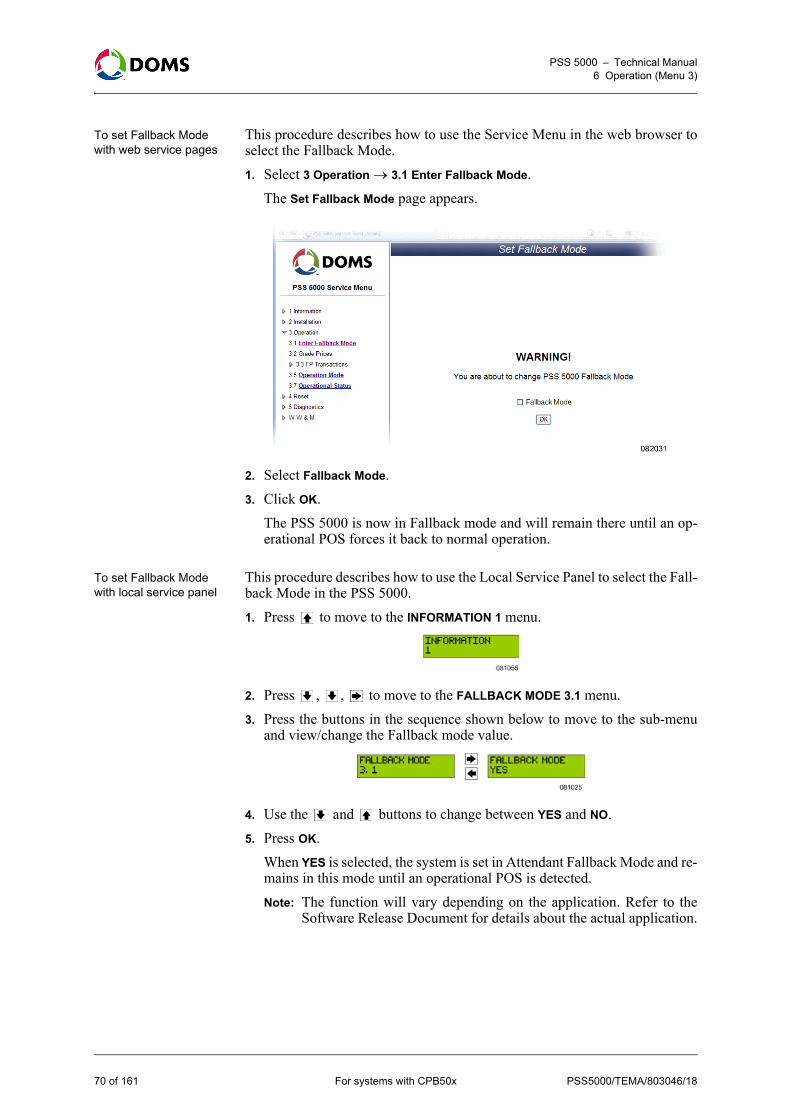
PSS 5000 – Technical Manual6 Operation (Menu 3)
To set Fallback Mode with web service pages
This procedure describes how to use the Service Menu in the web browser toselect the Fallback Mode.1. Select 3 Operation 3.1 Enter Fallback Mode.
The Set Fallback Mode page appears.
2. Select Fallback Mode.3. Click OK.
The PSS 5000 is now in Fallback mode and will remain there until an op-erational POS forces it back to normal operation.
To set Fallback Mode with local service panel
This procedure describes how to use the Local Service Panel to select the Fall-back Mode in the PSS 5000.1. Press to move to the INFORMATION 1 menu.
2. Press , , to move to the FALLBACK MODE 3.1 menu.3. Press the buttons in the sequence shown below to move to the sub-menu
and view/change the Fallback mode value.
4. Use the and buttons to change between YES and NO.5. Press OK.
When YES is selected, the system is set in Attendant Fallback Mode and re-mains in this mode until an operational POS is detected.Note: The function will vary depending on the application. Refer to the
Software Release Document for details about the actual application.
70 of 161 For systems with CPB50x PSS5000/TEMA/803046/18

PSS 5000 – Technical Manual6 Operation (Menu 3)
6.2 Grade Prices (Menu 3.2)
To set view/change grade prices with web service pages
This procedure describes how to use the Service Menu in the web browser toview/change the prices for the individual product grades.1. Select 3 Operation 3.2 Grade Prices.
The Grade Prices page appears.
2. Select the grade name and change the price(s) for the price group(s).3. If the price of more than one grade needs to be changed, repeat Step 2.4. Click ACCEPT.5. Click OK when asked to accept the prices.
A confirmation that the changes grade prices are accepted appears and thenthe page returns to the normal Grade Prices page, which shows a list ofproduct grades and prices.
To view/change grade prices with local service panel
This procedure describes how to use the Local Service Panel to view/changethe grade prices in the PSS 5000.Note: This function is not available for all Application Programs.1. Press to move to the INFORMATION 1 menu.
2. Press , , , to move to the GRADE PRICES 3.2 menu.3. Press the buttons in the sequence shown below to move to the sub-menus,
select the products and view the prices. Use and to change the prices.
PSS5000/TEMA/803046/18 For systems with CPB50x 71 of 161

PSS 5000 – Technical Manual6 Operation (Menu 3)
4. To change the prices for the remaining products, repeat Step 3. When youhave changed the price for the last product, you are ready to update the pric-es.
5. Press OK to set the new prices.
6.3 FP Transactions (Menu 3.3)
Overview of FP Transactions menu
The FP Transactions menu is divided in to the following sub-menus:• ‘6.3.1 Monitor (Menu 3.3.1)’ on page 72• ‘6.3.2 Log (Menu 3.3.2)’ on page 73
6.3.1 Monitor (Menu 3.3.1)
To monitor transactions Transactions from each fuelling point can be monitored with the TransactionMonitor page.This procedure describes how to use the Service Menu in the webbrowser to use POS Mode to monitor unpaid transactions.1. Select 3 Operation 3.3 FP Transactions 3.3.1 Monitor.
The Transaction Monitor page appears.
Each fuelling point is listed with the details of the latest unpaid transaction.Note: Money, Price and Volume values are shown as a number string. Refer
to the LAM (see ‘4.5 LAM (Menu 1.5)’ on page 35) to see the cor-rect position of the decimal point for each of the parameters.
2. Use the list to view which fuelling points have unpaid transactions.Note: Once the POS acknowledges payment the entry in the table is re-
moved.
72 of 161 For systems with CPB50x PSS5000/TEMA/803046/18

PSS 5000 – Technical Manual6 Operation (Menu 3)
6.3.2 Log (Menu 3.3.2)
To view the transaction log
This procedure describes how to use the Service Menu in the web browser toshow the last 10 fuel transactions.1. Select 3 Operation 3.3 FP Transactions 3.3.2 Log.
The Transaction Log page appears.
2. Use the list view the last 10 transactions, both paid and unpaid.Note: Error transactions are shown in red.
6.4 Payment Server (Menu 3.4)
Description of Payment Server menu
The Payment Server menu is used to control which cards that can be used onthe site.Note: Not all versions of the PSS 5000 application software include the pay-
ment server.
PSS5000/TEMA/803046/18 For systems with CPB50x 73 of 161

PSS 5000 – Technical Manual6 Operation (Menu 3)
To check the validity of a card
The Card Check menu enables you to check if a card is included in the whitelist loaded in the PSS 5000.1. Select 3 Operation 3.4 Payment Server 3.4.1 Card Check.
The Card Check page appears.
2. Type in the 20 digit number for the card and click Check.Information about the validity of the card appears.
6.5 Operation Mode (Menu 3.5)
Description of the Operation Mode
The operation mode for specific forecourt device can be changed by using theOperation Mode menu.Some application dependant operation modes might be available for specialpurposes such as disabling intrusion detection of an OPT, or setting an OPT inmaintenance mode to perform various technical tests on the OPT.
74 of 161 For systems with CPB50x PSS5000/TEMA/803046/18

PSS 5000 – Technical Manual6 Operation (Menu 3)
To view/set operation mode
This procedure describes how to use the Service Menu in the web browser toset the operation mode of specific forecourt devices.1. Select 3 Operation 3.5 Operation Mode.
The Set Operation Mode page appears.
2. In the Device Type field, select either the whole forecourt or a specific typeof device. Note: Only devices that are configured in the controller and can use the op-
eration mode are included in the list.Possible specific device types are:• Fuelling Point• Price Pole• Terminal
3. Open the drop-down list for Device ID and select the ID for a specific deviceor all IDs.When the Device ID is selected, then the current Operation Mode appears.
4. Open the drop-down list for Operation Mode and select the required mode.Confirmation of the selected operation mode appears briefly on screen.
5. Verify the values shown on screen are correct.
6.6 Menu 3.6 Reserved for Future Use
Reserved This menu is reserved for implementation of future features in the PSS 5000.
PSS5000/TEMA/803046/18 For systems with CPB50x 75 of 161

PSS 5000 – Technical Manual6 Operation (Menu 3)
6.7 Operational Status (Menu 3.7)
Description of Operational Status menu
The Operational Status menu provides the current status of all the forecourt de-vices connected to the PSS 5000. The status is updated automatically or, ifnecessary, can be updated manually. Note: The value for the automatic update period is defined in the Web Prefer-
ences page, see ‘5.4.4 Web Preferences (Menu 2.4.4)’ on page 57.By selecting a specific type of forecourt device, more detailed informationabout the individual devices appears.
To view operational status of forecourt devices
This procedure describes how to use the Service Menu in the web browser toview the operational status of the forecourt devices. 1. Select 3 Operation 3.7 Operational Status.
The Operational Status page appears.
This provides a status summary for all the forecourt devices connected tothe PSS 5000.
76 of 161 For systems with CPB50x PSS5000/TEMA/803046/18

PSS 5000 – Technical Manual6 Operation (Menu 3)
2. To see more details for a specific type of device, click on the hyperlink forthe device type at the top of the page. For example, click Fuelling Point.Now the Operational Status page contains only those devices for the select-ed type, and additional details appear. The example below is for fuellingpoints.
6.8 TeleTerminal (Menu 3.8)
Description of TeleTerminal
The TeleTerminal interface is used by some national bank card acquires, forexample Danish PBS. It is used when the transaction amount is known whenthe card is read. Note: This is currently only used for car wash sales.
6.9 Reconciliation Report (Menu 3.9)
Description of Reconciliation Report menu
Reconciliation reports provide a comparison between metered sales (measuredby the pumps) and gauged sales (measured by the tank gauge system). Bycomparing these two sources of information, it is possible to detect leaks, theftand other types of irregular product movements.Note: Before reconciliation reports can be created by the PSS 5000, it is im-
portant that the relationships between each of the fueling points and theassociated tanks are configured in the PSS 5000.
The Reconciliation Report page presents both Totalizer Readings and ATGReadings with start and stop time stamps. The Totalizer Readings are providedby the PSS 5000 and are metered sales values for each of the tanks associatedwith each fueling point. The ATG Readings are gauged tank volumes providedby the tank gauge system. The data required to create a reconciliation report is stored in the PSS 5000.Normally, this data is compiled once a day (24 hours) into a site report(site_rep.xml file). Although the PSS 5000 can store up to 3 of these reports,only the oldest report is available when requested using the xml output com-mand. When the reconciliation functionality is included in the forecourt application,it is possible to store up to 7 site_rep.xml files. All of these reports can beviewed on the Reconciliation Report page using the Service Menu in the PSS5000’s embedded web server. In addition to this, the Reconciliation Report
PSS5000/TEMA/803046/18 For systems with CPB50x 77 of 161

PSS 5000 – Technical Manual6 Operation (Menu 3)
page also allows you to create new reports manually. This means that you canincrease or decrease the frequency of the report generation.
Reconciliation report page parameters
The Reconciliation Report page (shown below) is available using the PSS5000 Service Menu.
The table below provides explanations for the various parameter fields presenton the Reconciliation Report page:
Parameter Description
Report Identifiers
System name This is the id assigned to the PSS 5000.
Number This shows which report is displayed.
Note: If the Number value is equal to or greaterthan 7, then there are 7 reconciliation reportsyou can view.
Period Start Provides the date (yyyy/mm/dd) and time (hh:mm) for the start of the reconciliation report.
Period End Provides the date (yyyy/mm/dd) and time (hh:mm) for the end of the reconciliation report.
Report Select Selector buttons that enable you to display the previous/next reconciliation report.
Note: Even though the Number value is greaterthan 7, only 7 reconciliation reports are avail-able.
Create Report? This Yes button enables you to create reports manually.
Note: When the Yes button is active, the auto-matic report generation (default time 00:00) isdisabled.
78 of 161 For systems with CPB50x PSS5000/TEMA/803046/18

PSS 5000 – Technical Manual6 Operation (Menu 3)
Manual report creation A check box and Enable/Disable button that al-low you to activate/deactivate the Create Report button.
Note: Both the check box and the button mustbe used to change the state of the Create Reportbutton.
Totalizer Readings (liter)
Fuelling Point n Each fuelling point has 3 values:
• Start – this value is provided by the previous Site report.
• End – this values is provided by the current Site report.
• Metered Sale – this is a calculated value:(End value – Start value)
Note: Depending on the type of pump, the Startand End values can be either measured valuesfrom the pump or calculated values from trans-action data.
Total Sale This is a summation of Metered Sale values for all the fuelling points connected to the tank.
ATG Readings (liter)
Gauged Volume: Start This is measured value from the tank gauge system when the previous site report was creat-ed.
Delivered This is measured value provided by tank gauge system, which states the amount of any deliver-ies made after the Start and before the End val-ues were provided.
Gauged Volume: End This is measured value from the tank gauge system when the current site report was creat-ed.
Tank Gauge Sale This is a calculated value:(End – Start) + Delivered
Reconciliations
Tank Group This is a tank group ID. It is only relevant when multiple tanks are manifolded.
Dif. (liters) This is a calculated value (for each tank), which compares the values supplied by the 2 sources:
Dif. (%) This is a calculated value (for each tank) which compares the values supplied by the 2 sources:
Parameter Description
Total Totalizer Sale Total Tank Gauge Sale–
Total Totalizer Sale Total Tank Gauge Sale– 100Total Totalizer Sale
-------------------------------------------------------------------------------------------------------------------------------
PSS5000/TEMA/803046/18 For systems with CPB50x 79 of 161

PSS 5000 – Technical Manual6 Operation (Menu 3)
To view reconciliation reports
This procedure describes how to use the Service Menu in the web browser toview the reconciliation reports stored in the PSS 5000.Note: Before reconciliation reports can be created by the PSS 5000, it is im-
portant that the relationships between each of the fueling points and theassociated tanks are configured in the PSS 5000.
1. Select 3 Operation 3.9 Reconciliation Report.The Reconciliation Report page appears.
The newest reconciliation report is displayed. It contains metered valuesfrom the pumps and gauged values from the tank gauge system. A compa-rision of these values is shown in the Reconciliations part of the table at thebottom of the Reconciliations Report.
2. Use the Report Select arrow buttons to view the remaining reconciliationreports.It is possible to view multiple reconciliation reports using this page.
3. If you want to change the status of the report generation, select the Manualreport creation check box and press the Enable/Disable button.If you pressed the Enable button, you are now able to create new reconcil-iation reports by pressing the Create Report? button.Note: Automatic report generation is deactivated when manual report cre-
ation is activated.If you pressed the Disable button, manual report creation is no longer pos-sible and the automatic report function is activated.Note: By default the automatic report generation occurs at 00:00 each day.
This time is configurable. Disabling the report auto-generation doesnot result in the time being reset to the default time.
80 of 161 For systems with CPB50x PSS5000/TEMA/803046/18

PSS 5000 – Technical Manual7 Reset (Menu 4)
7 Reset (Menu 4)
Overview of Reset menu The Reset menu is divided into the following sub-menus:• ‘7.1 Soft Reset (Menu 4.1)’ on page 81• ‘7.2 Master Reset (Menu 4.2)’ on page 82• ‘7.3 Super Master Reset (Menu 4.3)’ on page 83
7.1 Soft Reset (Menu 4.1)
Description of Soft Reset Activating the Soft Reset will have the same effect as a short power off. Thesystem stops for a short period and the hardware and communication driversare re-initialized, but the state of the operation starts from where it wasstopped.Note: When a Soft Reset or power down occurs, the contents of the virtual file
system pss_mem/4 is cleared.
To make a soft reset with web service pages
This procedure describes how to use the Service Menu in the web browser tomake a soft reset.1. Select 4 Reset 4.1 Soft Reset.
The Reset page appears.
2. Click RESET.The hardware and communication drivers are re-initialized and the soft-ware continues from where is was stopped.
To make a soft reset with local service panel
This procedure describes how to use the Local Service Panel to make a softreset.1. Press to move to the INFORMATION 1 menu.
2. Press , , , to move to the SOFT RESET 4.1 menu.
PSS5000/TEMA/803046/18 For systems with CPB50x 81 of 161

PSS 5000 – Technical Manual7 Reset (Menu 4)
3. Press to select the SOFT RESET? menu.
4. Use the and buttons to toggle between YES and NO.5. Select YES and press OK.
The system performs a soft reset.
7.2 Master Reset (Menu 4.2)
Description of a master reset
A Master Reset will, in general, clear the configuration data for the Applica-tion, for example, the configuration data for Fuelling Points and Tank Gauges.Some specific parameters, such as protocol to port assignments, IP address andthe like, are not cleared by a Master Reset.Note: When a Master Reset occurs, the contents of the virtual file system
pss_mem/4 and pss_mem/3 are cleared.
To make a master reset with web service pages
This procedure describes how to use the Service Menu in the web browser tomake a Master Reset.1. Select 4 Reset 4.2 Master Reset.
The Master Reset page appears.
2. Select Yes, I want to perform a master reset to confirm your actions.3. Click MASTER RESET.
The application configuration data is cleared.
To make a master reset with local service panel
This procedure describes how to use the Local Service Panel to make a MasterReset.1. Press to move to the INFORMATION 1 menu.
2. Press , , , , to move to the MASTER RESET 4.2 menu.
82 of 161 For systems with CPB50x PSS5000/TEMA/803046/18

PSS 5000 – Technical Manual7 Reset (Menu 4)
3. Press to select the MASTER RESET? menu.
4. Press and hold OK for 10 seconds.The system performs a master reset. The display shows OK MASTER RE-SET....
7.3 Super Master Reset (Menu 4.3)
Description of a super master reset
The Super Master Reset simply clears all the memory. All configuration dataand parameters, such as Port assignments, return to their default values.Note: When a Super Master Reset occurs, the contents of the virtual file sys-
tem pss_mem/4, pss_mem/3 and pss_mem/2 are cleared.
To make a super master reset with web service pages
This procedure describes how to use the Service Menu in the web browser tomake a Super Master Reset.1. Select 4 Reset 4.3 Super Master Reset.
The Super Master Reset page appears.
2. Type ACCEPT in the empty field.3. Click SUPER MASTER RESET.
All configuration settings return to their default values.
To make a super master reset with local service panel
This procedure describes how to use the Local Service Panel to make a SuperMaster Reset.1. Press to move to the INFORMATION 1 menu.
2. Press , , , , to move to the SUPER M RESET 4.3 menu.
PSS5000/TEMA/803046/18 For systems with CPB50x 83 of 161

PSS 5000 – Technical Manual7 Reset (Menu 4)
3. Press to select the SUPER M RESET? menu.
4. Press and hold OK + for 10 seconds.The system performs a Super Master Reset and the display shows ...SUPERMASTER RESET.
84 of 161 For systems with CPB50x PSS5000/TEMA/803046/18

PSS 5000 – Technical Manual8 Diagnostics (Menu 5)
8 Diagnostics (Menu 5)
Overview of Diagnostics menu
The Diagnostics menu is divided into the following sub-menus:• ‘8.1 Forecourt Devices (Menu 5.1)’ on page 85• ‘8.2 System Logs (Menu 5.2)’ on page 97• ‘8.3 Communication (Menu 5.3)’ on page 104• ‘8.4 Peep (Menu 5.4)’ on page 106• ‘8.5 Test (Menu 5.5)’ on page 109• ‘8.6 Peripherals (Menu 5.6)’ on page 109
8.1 Forecourt Devices (Menu 5.1)
Overview of Forecourt Devices information
From the Forecourt Devices menu you can see which devices are online andreceive status and error information for the forecourt devices. The menu is di-vided into the following sub-menus:• ‘8.1.1 Online List (Menu 5.1.1)’ on page 85• ‘8.1.2 Device Errors (Menu 5.1.2)’ on page 87• ‘8.1.3 Price Pole Test (Menu 5.1.3)’ on page 88• ‘8.1.4 Device Status (Menu 5.1.4)’ on page 90• ‘8.1.5 Device Test (Menu 5.1.5)’ on page 93
8.1.1 Online List (Menu 5.1.1)
Description of Online List menu
For each type of forecourt device there is access to a list of online devices.Even before the PSS is configured, it will start polling possible addresses oneach port, so this can be used to check that the installation and cabling has beenmade correctly.For protocols with large numbers of possible addresses (IP addresses or serialnumber), this is not possible and these will not be shown as online until theyare configured.
To list online devices with web service pages
This procedure describes how to use the Service Menu in the web browser toview a list of devices that are online.Note: The items listed in this list are devices associated with the forecourt,
such as pumps, tank gauges and the like.
PSS5000/TEMA/803046/18 For systems with CPB50x 85 of 161

PSS 5000 – Technical Manual8 Diagnostics (Menu 5)
1. Select 5 Diagnostics 5.1 Forecourt Devices5.1.1 Online List.The Online List page appears.
2. Use the list to see which devices are currently online. The columns containthe following information:
To list online devices with local service panel
This procedure describes how to use the Service Menu in the local service pan-el to view a list of devices that are online.1. Press to move to the INFORMATION 1 menu.
2. Press , , , , , to move to the ONLINE LIST 5.1.1 menu.3. Press the buttons in the sequence shown below to move to the sub-menus
and view which devices are connected to the individual ports.
Column Description
Port The number of the port on the PSS 5000 CPB to which the devices are connected.
Protocol List of protocols assigned to the port (see ‘5.1 Protocol to Port Assignment (Menu 2.1)’ on page 36).
Address The communication address of the device online.
Config. The ID that is assigned to the device during configura-tion and is used by the PSS 5000.
86 of 161 For systems with CPB50x PSS5000/TEMA/803046/18

PSS 5000 – Technical Manual8 Diagnostics (Menu 5)
8.1.2 Device Errors (Menu 5.1.2)
Description of Device Errors menu
From the Device Errors menu it is possible to view the latest error that has oc-curred on each device and/or view the last error for a specific device.Note: At present, only fuelling points and POS online information is available.
To view recent errors for all devices with web service pages
This procedure describes how to use the Service Menu in the web browser toview the latest error for each device.1. Select 5 Diagnostics 5.1 Forecourt Devices 5.1.2 Device Errors
5.1.2.1 Recent.The Recent Device Errors page appears.
2. Use the list to see when the most recent error for each device occurred.
To view recent errors for a specific device with web service pages
This procedure describes how to use the Service Menu in the web browser toview the latest error for a specific device.1. Select 5 Diagnostics 5.1 Forecourt Devices 5.1.2 Device Errors
5.1.2.2 Specific.The Device Errors page appears.
2. Open the Device Type drop-down list, select the specific device type.3. Click DEVICE TYPE OK.
PSS5000/TEMA/803046/18 For systems with CPB50x 87 of 161
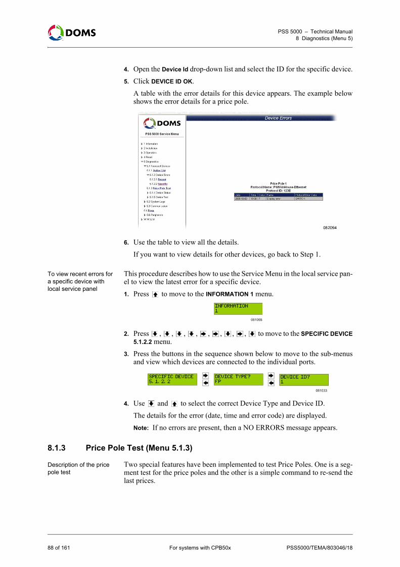
PSS 5000 – Technical Manual8 Diagnostics (Menu 5)
4. Open the Device Id drop-down list and select the ID for the specific device.5. Click DEVICE ID OK.
A table with the error details for this device appears. The example belowshows the error details for a price pole.
6. Use the table to view all the details. If you want to view details for other devices, go back to Step 1.
To view recent errors for a specific device with local service panel
This procedure describes how to use the Service Menu in the local service pan-el to view the latest error for a specific device.1. Press to move to the INFORMATION 1 menu.
2. Press , , , , , , , , to move to the SPECIFIC DEVICE5.1.2.2 menu.
3. Press the buttons in the sequence shown below to move to the sub-menusand view which devices are connected to the individual ports.
4. Use and to select the correct Device Type and Device ID.The details for the error (date, time and error code) are displayed.Note: If no errors are present, then a NO ERRORS message appears.
8.1.3 Price Pole Test (Menu 5.1.3)
Description of the price pole test
Two special features have been implemented to test Price Poles. One is a seg-ment test for the price poles and the other is a simple command to re-send thelast prices.
88 of 161 For systems with CPB50x PSS5000/TEMA/803046/18

PSS 5000 – Technical Manual8 Diagnostics (Menu 5)
To start a price pole test with web service pages
This procedure describes how to use the Service Menu in the web browser totest the price pole.1. Select 5 Diagnostics 5.1 Forecourt Devices5.1.3 Price Pole Test.
The Price Pole Test page appears.
2. Click START PRICE POLE TEST.The price pole test starts.
To start a price pole test with web service pages
This procedure describes how to use the Service Menu in the web browser totest the price pole by updating the prices shown on the pole.1. Select 5 Diagnostics 5.1 Forecourt Devices5.1.3 Price Pole Test.
The Price Pole Test page appears.
PSS5000/TEMA/803046/18 For systems with CPB50x 89 of 161
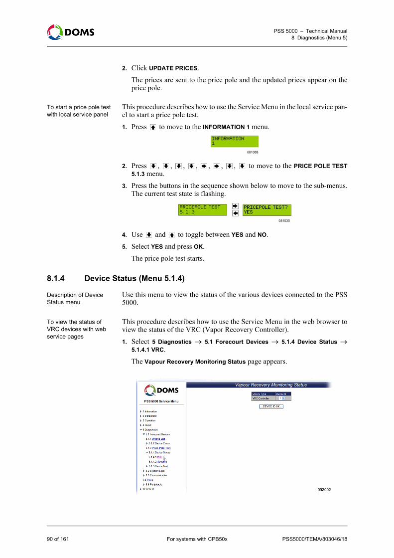
PSS 5000 – Technical Manual8 Diagnostics (Menu 5)
2. Click UPDATE PRICES.The prices are sent to the price pole and the updated prices appear on theprice pole.
To start a price pole test with local service panel
This procedure describes how to use the Service Menu in the local service pan-el to start a price pole test.1. Press to move to the INFORMATION 1 menu.
2. Press , , , , , , , to move to the PRICE POLE TEST5.1.3 menu.
3. Press the buttons in the sequence shown below to move to the sub-menus.The current test state is flashing.
4. Use and to toggle between YES and NO.5. Select YES and press OK.
The price pole test starts.
8.1.4 Device Status (Menu 5.1.4)
Description of Device Status menu
Use this menu to view the status of the various devices connected to the PSS5000.
To view the status of VRC devices with web service pages
This procedure describes how to use the Service Menu in the web browser toview the status of the VRC (Vapor Recovery Controller).1. Select 5 Diagnostics 5.1 Forecourt Devices 5.1.4 Device Status
5.1.4.1 VRC.The Vapour Recovery Monitoring Status page appears.
90 of 161 For systems with CPB50x PSS5000/TEMA/803046/18

PSS 5000 – Technical Manual8 Diagnostics (Menu 5)
2. Open the drop-down list for the VRC Controller and select a device ID forthe controller.
3. Click DEVICE ID OK.The most important Vapor Recovery Monitoring status information ap-pears.
4. If required, click Refresh to update the data shown on this page.
PSS5000/TEMA/803046/18 For systems with CPB50x 91 of 161

PSS 5000 – Technical Manual8 Diagnostics (Menu 5)
To view the status of specific devices with web service pages
This procedure describes how to use the Service Menu in the web browser toview the status of specific devices.1. Select 5 Diagnostics 5.1 Forecourt Devices 5.1.4 Device Status
5.1.4.2 Specific.The Device Status page appears.
Note: The Device Type list includes only those device types that are con-nected to and available from the PSS 5000.
2. In the Device Type list select the specific device type.
92 of 161 For systems with CPB50x PSS5000/TEMA/803046/18

PSS 5000 – Technical Manual8 Diagnostics (Menu 5)
3. Click Continue.The latest status for the selected device appears. The figure below is an ex-ample of a tank gauge.
The data is refreshed automatically every 15 seconds.4. If it is necessary to refresh the data more frequently, click Manual Refresh
to update immediately.
8.1.5 Device Test (Menu 5.1.5)
Description Device Test menu for VRC
The Special Vapor Recovery Monitoring functions for test and service canonly be accessed when you are logged on to the PSS 5000 System as a VRCuser.Log in details: User name: vrc, Password: password (default)
To view the internal VRM test functions with web service pages
This procedure describes how to use the Service Menu in the web browser toview the internal VRM (Vapor Recovery Monitoring) test functions.Note: You must be logged on with the user name: vrc.
PSS5000/TEMA/803046/18 For systems with CPB50x 93 of 161

PSS 5000 – Technical Manual8 Diagnostics (Menu 5)
1. Select 5 Diagnostics 5.1 Forecourt Devices5.1.5 Device Test 5.1.5.1VRC.The Vapour Recovery Monitoring Test page appears.
2. Open the Device Id drop-down list and select the ID for the selected devicetype.
3. Click DEVICE ID OK.A page with a list of test functions for the selected device appears.
4. In the Time to live with error(s) for entire VRM system field, type in the cor-rect value. Note: The format for Time to live ... values is HH:MM. The permitted range
is 00:01 to 99:59 hours, and the default value is 72 hours.
94 of 161 For systems with CPB50x PSS5000/TEMA/803046/18

PSS 5000 – Technical Manual8 Diagnostics (Menu 5)
5. From the list of test functions, select the function to be activated:
6. Click ACTIVATE to start the selected test function.The PSS 5000 replies with a message that informs you which function isactivated.
Device Test menu description for Terminal Text Test
The PSS 5000 has a built-in text bank. This makes it possible to show differenttexts in the terminal’s display. The actual text in the text bank changes depend-ing on which application programs are installed. The text in the text bank canbe viewed in the Appendix (*.apx) file released with the application program.The texts in the text bank are indexed. The individual texts can be sent to theterminals display either by a command from the POS or by using a device onthe forecourt, which is handled automatically by the PSS 5000. Instead of sending commands from a POS, or using the devices on the fore-court, the Terminal Text Test provides an easy method to check that the textsare shown correctly on the terminal display.It is possible to have up to 6 different languages in the text bank. Each lan-guage is indexed. So, it is possible to replace an unwanted language with onethat is required for the specific application.
Test function Description
None Returns to normal system mode.
Reset VR counters for fuelling point All Vapor Recovery counters for all the nozzles belonging to the selected fuel-ling point are reset.
Suspend disabling of fuelling point Disabling of the fuelling point is suspend-ed temporarily.
Simulate VR error on fuelling point Simulate a vapor recovery error on the selected fuelling point.
Simulate VR disabling on fuelling point Simulate vapor recovery disabling on the selected fuelling point.
Simulate VR disabling on nozzle n Simulate vapor recovery disabling of a specific nozzle on the fuelling point.
PSS5000/TEMA/803046/18 For systems with CPB50x 95 of 161

PSS 5000 – Technical Manual8 Diagnostics (Menu 5)
To view the available terminal display texts with web service pages
This procedure describes how to use the Service Menu in the web browser toview the terminal display texts available.1. Select 5 Diagnostics 5.1 Forecourt Devices5.1.5 Device Test 5.1.5.2
Terminal Text Test.The Terminal Text Test page appears.
The page contains several text navigation buttons. Before you use thesebuttons, read the following steps.
2. In the Text exposure time field, type in a number for the required number ofseconds you want the text to be displayed during the test sequence.
3. In the PSS Language code field, type in the code for the selected language.There are up to 6 language versions available. But the actual languages aredefined in the application program. To see which languages are availableand the Language code for each language, look in the Appendix (*.apx) filereleased with the software.Note: When adding text (language versions) for a terminal in the Appendix
file, you must use the same character set as that used by the terminal,for example ISO 8859-1.
4. Use the navigation buttons to navigate through the various tests.• Back: change the Text ID to the one prior to the ID number shown in
the Text id field.• Start: Start a test sequence that shows all the texts present in the text
bank. The sequence starts at Text id 1.• Pause: Stops the test sequence until Start is used to continue the test se-
quence from the Text id where it was paused.• Forward: Change the Text ID from the ID shown in the Text id field to
the next ID number in the sequence.• Stop: Stops the test sequence and returns the Text id field to 1.• Go To: Use this button if you want to jump directly to a specific Text id.
96 of 161 For systems with CPB50x PSS5000/TEMA/803046/18

PSS 5000 – Technical Manual8 Diagnostics (Menu 5)
8.2 System Logs (Menu 5.2)
Overview of System Logs information
From the System Logs menu you can see several types of log information. Themenu is divided into the following sub-menus:• ‘8.2.1 Upload Log (Menu 5.2.1)’ on page 97• ‘8.2.2 Reset Logs (Menu 5.2.2)’ on page 98• ‘8.2.3 Application Log (Menu 5.2.3)’ on page 101• ‘8.2.4 Access Log (Menu 5.2.4)’ on page 102• ‘8.2.5 Board Error Log (Menu 5.2.5)’ on page 103
8.2.1 Upload Log (Menu 5.2.1)
Description of the Upload Log menu
The Upload Log menu provides a record of when the LAM and applicationsoftware were uploaded to the PSS 5000. Each record contains a date stamp,the software version number and an ID of the user who made the upload.
To view the Upload Log with web service pages
This procedure describes how to use the Service Menu in the web browser toview the upload log for the PSS 5000.1. Select 5 Diagnostics 5.2 System Logs5.2.1 Upload Log.
The Upload Log page appears.
2. Use the list of upload entries to see when the uploads occurred, the softwareversions and who made the uploads.
To view the Upload Log with local service panel
This procedure describes how to use the Service Menu in the local service pan-el to view the upload log.1. Press to move to the INFORMATION 1 menu.
2. Press , , , , , , to move to the UPLOAD LOG 5.2.1 menu.3. Press enter the upload log.
PSS5000/TEMA/803046/18 For systems with CPB50x 97 of 161
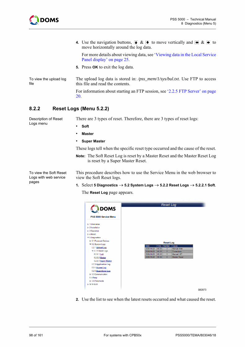
PSS 5000 – Technical Manual8 Diagnostics (Menu 5)
4. Use the navigation buttons, & to move vertically and & tomove horizontally around the log data. For more details about viewing data, see ‘Viewing data in the Local ServicePanel display’ on page 25.
5. Press OK to exit the log data.
To view the upload log file
The upload log data is stored in: /pss_mem/1/sys/bul.txt. Use FTP to accessthis file and read the contents.For information about starting an FTP session, see ‘2.2.5 FTP Server’ on page20.
8.2.2 Reset Logs (Menu 5.2.2)
Description of Reset Logs menu
There are 3 types of reset. Therefore, there are 3 types of reset logs: • Soft
• Master
• Super Master
These logs tell when the specific reset type occurred and the cause of the reset.Note: The Soft Reset Log is reset by a Master Reset and the Master Reset Log
is reset by a Super Master Reset.
To view the Soft Reset Logs with web service pages
This procedure describes how to use the Service Menu in the web browser toview the Soft Reset logs.1. Select 5 Diagnostics 5.2 System Logs5.2.2 Reset Logs 5.2.2.1 Soft.
The Reset Log page appears.
2. Use the list to see when the latest resets occurred and what caused the reset.
98 of 161 For systems with CPB50x PSS5000/TEMA/803046/18

PSS 5000 – Technical Manual8 Diagnostics (Menu 5)
To view the Master Reset Logs with web service pages
This procedure describes how to use the Service Menu in the web browser toview the Master Reset logs.1. Select 5 Diagnostics 5.2 System Logs5.2.2 Reset Logs 5.2.2.2 Mas-
ter.The Master Reset Log page appears.
This log has only a single entry, which shows when the last Master Resetoccurred.
PSS5000/TEMA/803046/18 For systems with CPB50x 99 of 161
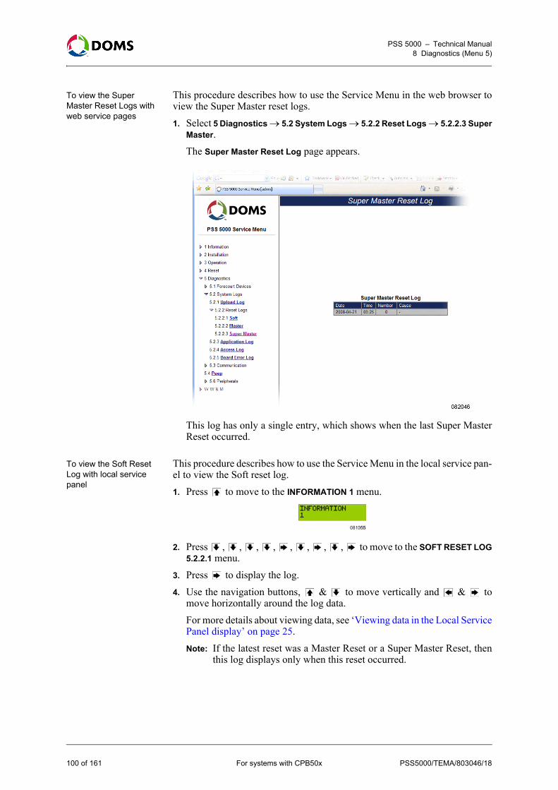
PSS 5000 – Technical Manual8 Diagnostics (Menu 5)
To view the Super Master Reset Logs with web service pages
This procedure describes how to use the Service Menu in the web browser toview the Super Master reset logs.1. Select 5 Diagnostics 5.2 System Logs5.2.2 Reset Logs 5.2.2.3 Super
Master.The Super Master Reset Log page appears.
This log has only a single entry, which shows when the last Super MasterReset occurred.
To view the Soft Reset Log with local service panel
This procedure describes how to use the Service Menu in the local service pan-el to view the Soft reset log.1. Press to move to the INFORMATION 1 menu.
2. Press , , , , , , , , to move to the SOFT RESET LOG5.2.2.1 menu.
3. Press to display the log.4. Use the navigation buttons, & to move vertically and & to
move horizontally around the log data. For more details about viewing data, see ‘Viewing data in the Local ServicePanel display’ on page 25.Note: If the latest reset was a Master Reset or a Super Master Reset, then
this log displays only when this reset occurred.
100 of 161 For systems with CPB50x PSS5000/TEMA/803046/18

PSS 5000 – Technical Manual8 Diagnostics (Menu 5)
To view the Master Reset Log with local service panel
This procedure describes how to use the Service Menu in the local service pan-el to view the Master reset log.1. Press to move to the INFORMATION 1 menu.
2. Press , , , , , , , , , to move to the MASTER RE-SET LOG 5.2.2.2 menu.
3. Press to display the log.The log contains a single line – a date and time stamp, which tells when thelast Master Reset occurred.
To view the Super Master Reset Log with local service panel
This procedure describes how to use the Service Menu in the local service pan-el to view the Super Master reset log.1. Press to move to the INFORMATION 1 menu.
2. Press , , , , , , , , , , to move to the SUPERMASTER RESET LOG 5.2.2.3 menu.
3. Press to display the log.The log contains a single line – a date and time stamp, which tells when thelast Master Reset or Super Master Reset occurred.
8.2.3 Application Log (Menu 5.2.3)
Description of the Application Log menu
The application log is used for various application program issues, for exam-ple, to indicate "Initialization complete" or the status of "CRC error".
To view the Application Log with web service pages
This procedure describes how to use the Service Menu in the web browser toview the Application Logs.1. Select 5 Diagnostics 5.2 System Logs5.2.3 Application Log.
The Application Log page appears.
PSS5000/TEMA/803046/18 For systems with CPB50x 101 of 161

PSS 5000 – Technical Manual8 Diagnostics (Menu 5)
To view the Application Log with local service panel
This procedure describes how to use the Service Menu in the local service pan-el to view the Application Log.1. Press to move to the INFORMATION 1 menu.
2. Press , , , , , , , , to move to the APPLICATIONLOG 5.2.3 menu.
3. Press to display the log.
To view the application log file
The application log is stored in: /pss_mem/2/appl/applog.txt. Use FTP to ac-cess this file and then view the contents.For information about starting an FTP session, see ‘2.2.5 FTP Server’ on page20.
8.2.4 Access Log (Menu 5.2.4)
Description of Access Log
The Access Log menu shows who has logged on and when the log on occurred.
To view the Access log with web service pages
This procedure describes how to use the Service Menu in the web browser toview the Access log.1. Select 5 Diagnostics 5.2 System Logs5.2.4 Access Log.
The Access Log page appears.
2. Use the details in the table to see who logged on and when.
102 of 161 For systems with CPB50x PSS5000/TEMA/803046/18
PSS 5000 – Technical Manual8 Diagnostics (Menu 5)
To view the Access Log with local service panel
This procedure describes how to use the Service Menu in the local service pan-el to view the Access log.1. Press to move to the INFORMATION 1 menu.
2. Press , , , , , , , , , to move to the ACCESS LOG5.2.4 menu.
3. Press to display the log.4. Use the navigation buttons, & to move vertically and & to
move horizontally around the log data. For more details about viewing data, see ‘Viewing data in the Local ServicePanel display’ on page 25.
8.2.5 Board Error Log (Menu 5.2.5)
Description of Board Error Log
The Board Error Log menu shows all the fatal errors that have occurred on thePSS 5000 CPU board.
To view the Board Error log with web service pages
This procedure describes how to use the Service Menu in the web browser toview the Board Error log.1. Select 5 Diagnostics 5.2 System Logs5.2.5 Board Error Log.
The Board Error Log page appears.
2. Use the scroll bars to view the details in the table.
To view the board error log file
The board error log is stored in: /pss_proc/sys/bel.txt. Use FTP to access thisfile and view the contents.For information about starting an FTP session, see ‘2.2.5 FTP Server’ on page20.
PSS5000/TEMA/803046/18 For systems with CPB50x 103 of 161

PSS 5000 – Technical Manual8 Diagnostics (Menu 5)
8.3 Communication (Menu 5.3)
Overview of Communication information
From the Communication menu you can see which communication statisticsand protocols are available. The menu is divided into the following sub-menus:• ‘8.3.1 Ethernet Statistics (Menu 5.3.1)’ on page 104• ‘8.3.2 Port Statistics (Menu 5.3.2)’ on page 104• ‘8.3.3 Protocols (Menu 5.3.3)’ on page 105
8.3.1 Ethernet Statistics (Menu 5.3.1)
Description of Ethernet Statistics menu
The Ethernet Statistics menu provides data about the network communication.Information about the amount of traffic, and the number of bad frames andoverruns is displayed.
To view the Ethernet Statistics with web service pages
This procedure describes how to use the Service Menu in the web browser toview the Ethernet Statistics.1. Select 5 Diagnostics 5.3 Communication5.3.1 Ethernet Statistics.
The Ethernet Statistics page appears.
2. If necessary, click RESET STATISTICS to set all counters to 0.
8.3.2 Port Statistics (Menu 5.3.2)
Description of Port Statistics menu
The Port Statistics menu provides data about the amount of traffic and thenumber of errors present on each of the ports on the PSS 5000 CPU board.
104 of 161 For systems with CPB50x PSS5000/TEMA/803046/18

PSS 5000 – Technical Manual8 Diagnostics (Menu 5)
To view the Port Statistics with web service pages
This procedure describes how to use the Service Menu in the web browser toview the PSS 5000 statistics for the communication ports on the CPU board.1. Select 5 Diagnostics 5.3 Communication5.3.2 Port Statistics.
The Communication Port Statistics page appears.
2. Use the information in the table to see the traffic load on each port andwhere, if any, errors have occurred.
8.3.3 Protocols (Menu 5.3.3)
Description of Protocols menu
The Protocols menu provides a list of protocols assigned to the individualports on the PSS 5000 CPU board.
PSS5000/TEMA/803046/18 For systems with CPB50x 105 of 161

PSS 5000 – Technical Manual8 Diagnostics (Menu 5)
To view the Protocols with web service pages
This procedure describes how to use the Service Menu in the web browser toview the protocol to port assignments in the PSS 5000.1. Select 5 Diagnostics 5.3 Communication5.3.3 Protocols.
The Protocol Diagnostics page appears.
2. Click Select to view a list of error counters for the selected protocol.Note: The Select button is only available for certain protocols with specific
Application software.
8.4 Peep (Menu 5.4)
Description of the Peep menu
The PSS 5000 has an embedded communication dump facility, which is calleda peep. The peep can basically run in two different modes. These modes aredescribed in the table below:
Mode Description
Peep File Swap When running in the swap mode the peeper will swap between two file series, a and b. For example:
peepfile.a00... peepfile.b00... peepfile.a00...
This continues until the sequence number is increased manually by a user pressing the 'Skip' button. This is typically done when an 'interesting' event has occurred. After this, the peeper will continue swapping between peepfile.a01... peepfile.b01... peepfile.a01... and so on.
Peep File Incremental When running in the incremental mode the peeper will create a continuous series of peep files.
The file extension is cxx, where xx is a 2 digit sequence number from 00 to 99. After peepfile.c99 the peeper automatically continues with d00... d99... e00... e99... ...z99.
106 of 161 For systems with CPB50x PSS5000/TEMA/803046/18

PSS 5000 – Technical Manual8 Diagnostics (Menu 5)
Note: Each file can be named with an optional file name (default is peepfile)and with an extension letter followed by a 2 digit sequence number(from 00 to 99).
When the Java Peep Applet is started via the systems home page, it is possibleto start the peeper facility and collect peeper trace files (peep files) from thePSS 5000 system and store them on the connected PC.The Peeper Applet has a digital signature from VeriSign. This proves that it isan authentic Doms Java Applet. When the Applet is activated you are prompt-ed to accept the digital signature. This ensures that the peep files are written tothe hard disk. If the signature is not accepted, then the peep applet doesn’t run.
To start peep with web service pages
This procedure describes how to use the Service Menu in the web browser tostart the peeper.1. Select 5 Diagnostics 5.4 Peep.
The Peep Setup page appears.
2. Select the ports where the peeper is to be active.Note: Port 41 is always selected. In addition to this, the following ports are
also selected: – ports selected the last time the page was open– ports where the PSS 5000 has received more than 100 counters.
3. Click START PEEP.
PSS5000/TEMA/803046/18 For systems with CPB50x 107 of 161

PSS 5000 – Technical Manual8 Diagnostics (Menu 5)
Note: If you have not used this function previously, click Run to accept thedigital signature when the security warning appears.
The Java Applet starts and the Peeper page appears.
4. In the Settings group box, provide the following information:
5. Click Rec to begin creating the peep file(s).The screen shows which peep file is currently active. The TX and RXcounters change while data is being collected. If you want to jump to thenext peep file in the sequence, click Skip.
Field Action
User ID Type in your ID to make identification easier.
This information appears at the top of the peep file.
Notes Provide a short description of the prob-lem.
This information appears at the top of the peep file.
Peep directory Use the Browse button to define the lo-cation for the peep file(s).
Peep filename Type in the name to assign to the file(s).
Note: Peep directory and filename mustnot exceed 100 characters.
Max. file size (Kb) Define the maximum size of the separate peep files.
Range: 1, 2, 3, ..., 1000, ..., 9998, 9999
Increment extension Select this check box if the incremental mode is used.
Start from 0 Select this check box if only one file (a00 (swap) or c00 (incremental)) is required.
108 of 161 For systems with CPB50x PSS5000/TEMA/803046/18
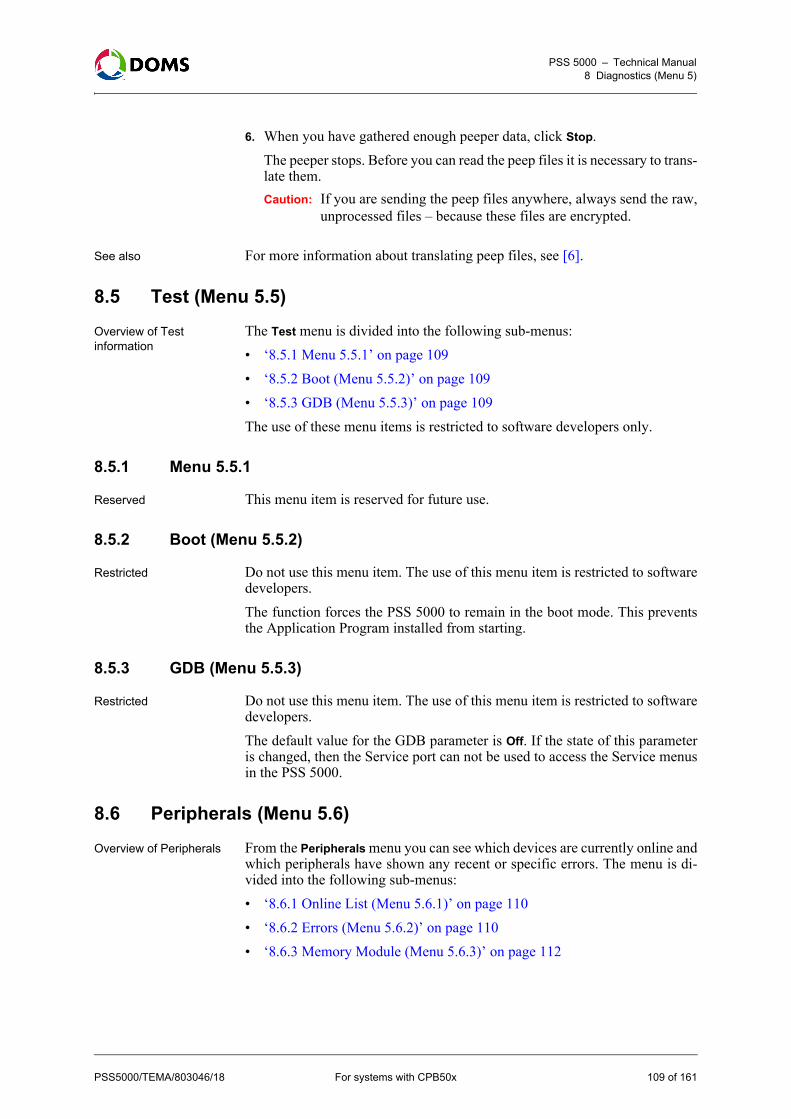
PSS 5000 – Technical Manual8 Diagnostics (Menu 5)
6. When you have gathered enough peeper data, click Stop.The peeper stops. Before you can read the peep files it is necessary to trans-late them. Caution: If you are sending the peep files anywhere, always send the raw,
unprocessed files – because these files are encrypted.
See also For more information about translating peep files, see [6].
8.5 Test (Menu 5.5)
Overview of Test information
The Test menu is divided into the following sub-menus:• ‘8.5.1 Menu 5.5.1’ on page 109• ‘8.5.2 Boot (Menu 5.5.2)’ on page 109• ‘8.5.3 GDB (Menu 5.5.3)’ on page 109The use of these menu items is restricted to software developers only.
8.5.1 Menu 5.5.1
Reserved This menu item is reserved for future use.
8.5.2 Boot (Menu 5.5.2)
Restricted Do not use this menu item. The use of this menu item is restricted to softwaredevelopers.The function forces the PSS 5000 to remain in the boot mode. This preventsthe Application Program installed from starting.
8.5.3 GDB (Menu 5.5.3)
Restricted Do not use this menu item. The use of this menu item is restricted to softwaredevelopers.The default value for the GDB parameter is Off. If the state of this parameteris changed, then the Service port can not be used to access the Service menusin the PSS 5000.
8.6 Peripherals (Menu 5.6)
Overview of Peripherals From the Peripherals menu you can see which devices are currently online andwhich peripherals have shown any recent or specific errors. The menu is di-vided into the following sub-menus:• ‘8.6.1 Online List (Menu 5.6.1)’ on page 110• ‘8.6.2 Errors (Menu 5.6.2)’ on page 110• ‘8.6.3 Memory Module (Menu 5.6.3)’ on page 112
PSS5000/TEMA/803046/18 For systems with CPB50x 109 of 161

PSS 5000 – Technical Manual8 Diagnostics (Menu 5)
8.6.1 Online List (Menu 5.6.1)
Description of online list menu
The Online List menu provides a list of all the peripherals currently online withthe PSS 5000.
To view the peripherals online with web service pages
This procedure describes how to use the Service Menu in the web browser toview which peripherals are connected to the ports of the CPU board.Note: The items listed in this list are devices associated with the PSS 5000, for
example a memory module.1. Select 5 Diagnostics 5.6 Peripherals 5.6.1 Online List.
The Peripherals Online List page appears.
2. Use the list to see which peripherals are actually connected to the ports ofthe CPU board.
8.6.2 Errors (Menu 5.6.2)
Description of Errors menu
The Errors menu enables you to see all the recent errors on all the peripherals.Alternatively, you can create a list of errors for specific types of peripheral de-vices.
110 of 161 For systems with CPB50x PSS5000/TEMA/803046/18

PSS 5000 – Technical Manual8 Diagnostics (Menu 5)
To view recent errors with web service pages
This procedure describes how to use the Service Menu in the web browser toview which errors have occurred recently on the peripherals.1. Select 5 Diagnostics 5.6 Peripherals 5.6.2 Errors 5.6.2.1 Recent.
The Recent Peripheral Errors page appears.
2. Use the list to see where errors have occurred recently on the peripherals.
To view errors on specific peripherals with web service pages
This procedure describes how to use the Service Menu in the web browser tosee where errors have occurred on specific peripheral device types.1. Select 5 Diagnostics 5.6 Peripherals 5.6.2 Errors 5.6.2.2 Specific.
The Peripheral Errors page appears.
2. Open the Device Type drop-down list and select the peripheral device type.3. Click DEVICE TYPE OK.4. Open the Device ID drop-down list and select the ID number for the specific
peripheral.
PSS5000/TEMA/803046/18 For systems with CPB50x 111 of 161

PSS 5000 – Technical Manual8 Diagnostics (Menu 5)
5. Click DEVICE ID OK.A list of errors for the specific peripheral device appears.
6. Use the list to view the errors that have occurred on the selected peripheraldevice.
8.6.3 Memory Module (Menu 5.6.3)
Description of Memory Module menu
Using the Memory Module menu enables you to see the ID of the sites wherethe modules have been used previously, the total memory capacity of the mod-ule and how much free-space is still available on the module.
To view status of the memory module with web service pages
This procedure describes how to use the Service Menu in the web browser toview the status of the memory module(s) installed in the PSS 5000.1. Select 5 Diagnostics 5.6 Peripherals 5.6.3 Memory Module 5.6.3.1
Status.The Memory Module Status page appears.
2. Use the information on the page to view the details for the memory module,where it is installed, the total amount of memory and the amount of free-memory still available.
112 of 161 For systems with CPB50x PSS5000/TEMA/803046/18

PSS 5000 – Technical Manual8 Diagnostics (Menu 5)
Note: If multiple modules are installed, the details for each module appearin separate tables.
To view errors on specific peripherals with web service pages
This procedure describes how to use the Service Menu in the web browser tosee where memory modules that have been installed previously were used.Note: Each time a memory module is installed, the site details are logged in
the memory of the memory module.1. Select 5 Diagnostics 5.6 Peripherals 5.6.3 Memory Module 5.6.3.2
History.The Memory Module History page appears.Note: It may take some time to display this page.
2. Use the information on the page to view the details of where the memorymodule has been installed previously.
PSS5000/TEMA/803046/18 For systems with CPB50x 113 of 161

PSS 5000 – Technical Manual9 W & M (Menu W)
9 W & M (Menu W)
Overview of W & M menu The W & M menu is divided into the following sub-menus:• ‘9.1 LAM Version (Menu W.1)’ on page 114• ‘9.2 LAM Parameters (Menu W.2)’ on page 115• ‘9.3 Memory Module Version (Menu W.3)’ on page 117• ‘9.4 Program Upload Log (Menu W.4)’ on page 118• ‘9.5 Recent Transactions (Menu W.5)’ on page 119• ‘9.6 Payment Log (Menu W.6)’ on page 119• ‘9.7 Checking Devices (Menu W.7)’ on page 121
Description The PSS 5000 contains several Weights and Measures facilities. These facili-ties ensure the correct operational status of the PSS 5000 and the integrity ofthe data it collects and stores. The facilities continually check that operationalcritical functions, such as the Local Service Panel display, are functioning cor-rectly. Should an error occur in one or more of these functions, then the W&Mfacilities will ensure that large transactions or unattended terminal paymentscannot continue until the error is corrected.The W&M Menu enables you to obtain important information about the PSS5000 system and provides a way for you to check that the W&M facilities arefunctioning correctly. You are able to simulate an error on one or more of theoperational critical functions, for example the Local Service Panel display,and see if the PSS 5000 reacts accordingly. By being able to do this and seethe results, you can verify that no errors are present on any of the checking fa-cilities.
LSP Idle menu For all the local service panel procedures, it is assumed that the Idle menu isshown in the display at the start of the procedure. For more information aboutthe idle menu, see ‘Local Service Panel display’ on page 24.
9.1 LAM Version (Menu W.1)
To view the LAM version with web service pages
This procedure describes how to use the Service Menu in a web browser toview the version and checksum number of the LAM currently loaded in thePSS 5000.Note: It is assumed that the Service Menu is already open in a web browser
application.
114 of 161 For systems with CPB50x PSS5000/TEMA/803046/18

PSS 5000 – Technical Manual9 W & M (Menu W)
1. Select W W & M W.1 LAM Version.The LAM Version window appears.
2. Read the LAM version and the date when the LAM file was created fromthe table.
To view the LAM version with local service panel
This procedure describes how to use the Local Service Panel to view the ver-sion and checksum number of the LAM currently loaded in the PSS 5000.Note: It is assumed that the Idle menu is shown in the display.1. Press to move to the LAM VERSION W.1 menu.
2. Press to move to the LAM VERS. CHKSUM menu.
View the LAM version and checksum data for the LAM installed.
9.2 LAM Parameters (Menu W.2)
Description of LAM parameters
The LAM parameters are specific for each version for the LAM. For specificdetails, please see the country specific LAM documentation.
PSS5000/TEMA/803046/18 For systems with CPB50x 115 of 161

PSS 5000 – Technical Manual9 W & M (Menu W)
To view LAM parameters with web service pages
This procedure describes how to use the Service Menu in the web browser toview the LAM parameters for the current LAM.1. Select W W & M W.2 LAM Parameters.
The LAM Parameters page appears.
Note: The actual parameters displayed depend on the actual LAM loadedin the PSS 5000
2. Use the list to view the actual LAM parameters.
To view LAM parameters with local service panel
This procedure describes how to use the Local Service Panel to view the ver-sion and checksum number of the LAM currently loaded in the PSS 5000.Note: It is assumed that the Idle menu is shown in the display.1. Press to move to the LAM VERSION W.1 menu.
2. Press to move to the LAM PARAMETERS W.2 menu. 3. Press to move to the first LAM parameter.
4. Use the 4 navigation buttons to move through the LAM parameters andview the set values.
5. Press to stop viewing the parameters and return to LAM PARAMETERSW.2.
116 of 161 For systems with CPB50x PSS5000/TEMA/803046/18

PSS 5000 – Technical Manual9 W & M (Menu W)
6.
9.3 Memory Module Version (Menu W.3)
Description of Memory Module Version menu
Using the Memory Module Version menu, you can view the program versionand checksum for each memory module.Note: This menu is only relevant if the PSS 5000 is configured with at least
one memory module and the memory module(s) must be configured inthe setup.ini file. For information about configuring the file see‘5.7 Peripheral Configuration (Menu 2.7)’ on page 65.
To view the memory module details with web service pages
This procedure describes how to use the Service Menu in the web browser toview the memory module details.1. Select W W & M W.3 Memory Module Version.
The Memory Module Info page appears.
2. Use the information on screen to see how many memory modules are in-stalled, the ID of each module and to which CPB port(s) they are connect-ed.
To view the memory module details with local service panel
This procedure describes how to use the Service Menu in the local service pan-el to view the memory module details.1. Press to move to the LAM VERSION W.1 menu.
2. Press , to move to MEM. MODULE INFO W.3 menu.3. Press to move to the sub-menus and view the details for the memory
module(s).
PSS5000/TEMA/803046/18 For systems with CPB50x 117 of 161

PSS 5000 – Technical Manual9 W & M (Menu W)
9.4 Program Upload Log (Menu W.4)
Description of the Upload Log menu
The upload log menu provides a record of when the LAM and application soft-ware were uploaded to the PSS 5000. Each record contains a date stamp, thesoftware version number and an ID of the user who made the upload.
To view upload log with web service pages
This procedure describes how to use the Service Menu in the web browser toview the upload log details.1. Select W W & M W.4 Program Upload Log.
The Upload Log page appears.
2. Use the list of upload entries to see when the uploads occurred.
To view the upload log with local service panel
This procedure describes how to use the Service Menu in the local service pan-el to view the upload log details.1. Press to move to the LAM VERSION W.1 menu.
2. Press , , to move to PROG UPLOAD LOG W.4 menu.3. Press to move to view the upload log data.
4. Use the 4 navigation buttons to move around upload log data.5. Press to stop viewing the data and return to PROG UPLOAD LOG W.4.
See also For more information about viewing the details in the log, see:• ‘Viewing data in the Local Service Panel display’ on page 25
118 of 161 For systems with CPB50x PSS5000/TEMA/803046/18

PSS 5000 – Technical Manual9 W & M (Menu W)
9.5 Recent Transactions (Menu W.5)
To view Recent Transactions data with local service panel
This procedure describes how to use the Local Service Panel to view all thedata for recent transactions that have taken place in the PSS 5000.Note: It is assumed that the Idle menu is shown in the display.1. Press to move to the LAM VERSION W.1 menu.
2. Press , , , to move to the RECENT TRANSAC. W.5 menu.
3. Press to move to the PUMP NUMBER? menu.
4. Press or to select the number of the pump from which you want toview data.
5. Press to move to the transaction data of the selected pump.
6. Use the navigation buttons to view the transactions data for the selectedpump.
7. Press to exit the transaction data and return to the RECENT TRANSAC.W.5 menu.
See also For more information about the format of recent transaction data:• ‘A.1 Recent Transactions File Format’ on page 129.
9.6 Payment Log (Menu W.6)
Description of the payment log menu
The Payment Log menu is used to view the payment log for unattended trans-actions, such as paid BNA (bank note) and Card transactions. The transactionpayment log is stored on the PSS Flash Memory Module.A payment record is selected and identified by the transaction type (Note orCard), date and a 4-digit receipt number. Any transaction with the wrongLogRecordAuthenticationCode will be marked with 'LOGERR'.
PSS5000/TEMA/803046/18 For systems with CPB50x 119 of 161

PSS 5000 – Technical Manual9 W & M (Menu W)
To view the payment log data with web service pages
This procedure describes how to use the Service Menu in the web browser toview data for payments that have taken place recently1. Select W W & M W.6 Payment Log.
The Payment Log page appears.
2. Use the information on screen to view the most recent payment log records.
To view payment log data with local service panel
This procedure describes how to use the Local Service Panel to view all thedata for payments that have taken place in the PSS 5000.Note: It is assumed that the Idle menu is shown in the display.1. Press to move to the LAM VERSION W.1 menu.
2. Press , , , , to move to the PAYMENT LOG W.6 menu. 3. Press the buttons in the sequence shown below to move to the sub-menus
and view the payment log data.
Use or to change values or selections in the sub-menus. 4. When the correct record log is located, use the navigation buttons to view
the data in the whole record.If no transactions are present, then the following message appears.
See also For more information about the format of transaction log file format:• ‘A.2 Transaction Log File Format’ on page 130.
120 of 161 For systems with CPB50x PSS5000/TEMA/803046/18

PSS 5000 – Technical Manual9 W & M (Menu W)
9.7 Checking Devices (Menu W.7)
Overview of Checking Devices menu
From the sub-menus under the Checking Devices menu, you can see which de-vices are online and get status and error information for the forecourt devices.The Checking Devices menu is divided into the following sub-menus:• ‘9.7.1 Display Error (Menu W.7.1)’ on page 122• ‘9.7.2 Send Error Security Telegram (Menu W.7.2)’ on page 123• ‘9.7.3 LAM Code Error (Menu W.7.3)’ on page 123• ‘9.7.4 RTC Error (Menu W.7.4)’ on page 124• ‘9.7.5 Trans Memory (Menu W.7.5)’ on page 125
Description of the Checking Devices menu
The Checking Devices menu is a way to check/test the functionality of the PSS5000. By activating the built-in checking device(s), which simulate/introducevarious errors or malfunction states, and observing the reaction(s), it is possi-ble to see if the tested functions in the PSS 5000 are behaving correctly.
To activate checking devices with web service pages
This procedure describes how to use the checking device functions in the Ser-vice Menu. By simulating an error on an operational critical function you areable to make sure that the checking facility in the PSS 5000 registers the errorand responds in the correct manner.1. Select W W&M W.7 Checking Devices W.7.x <sub-menu>.
Where the <sub-menu> selection is one of those present in the list.The steps below provide an example for using the Checking Devices menu,where the sub-menu W.7.1 Display Error is selected.
2. Select W W&M W.7 Checking Devices W.7.1 Display Error.The Checking Devices window appears.
Note: Although it is possible to select more than one checking device, werecommend that you select only one. Alternatively, start with a sin-gle checking device and then, if necessary, select an additional one.
3. Select the checking device option you want to activate.
PSS5000/TEMA/803046/18 For systems with CPB50x 121 of 161
PSS 5000 – Technical Manual9 W & M (Menu W)
4. Press ACCEPT.The message Checking devices set OK appears. This informs you that theselected device now has a simulated error present.
5. You are now able to check that the PSS 5000 has responded in the correctway.
6. Select W.7 Checking Devices again.7. In the Checking Devices window, clear the selection from the checking de-
vice error selected in Step 3.8. Press ACCEPT.
Failure to clear the checking device error results in the PSS 5000 not beingfully operational.
9. If you want to start another checking device, repeat Steps 3. through 8.
9.7.1 Display Error (Menu W.7.1)
To activate display errors with web service pages
The procedure used here is the same procedure as is used to check all the de-vices, see ‘To activate checking devices with web service pages’ on page 121.
To activate display errors with local service panel
This procedure describes how to activate the built-in checking device thatmakes sure that the Local Service Panel display checking facility is operatingcorrectly.Note: It is assumed that the Idle menu is shown in the display.1. Press to move to the LAM VERSION W.1 menu.
2. Press , , , , , to move to the CHECKING DEVICES W.7menu.
3. Press , to move to the DISPLAY ERROR menu.
4. Use the and buttons to toggle between ON and OFF. 5. Press to activate the selected state.
When the Display Error value is ON, this simulates that there is an error onthe display. The PSS 5000 must react accordingly.
Note: Remember to return the checking device setting to OFF before you leavethe PSS 5000. Failure to do this will result in the PSS 5000 not operatingcorrectly.
122 of 161 For systems with CPB50x PSS5000/TEMA/803046/18

PSS 5000 – Technical Manual9 W & M (Menu W)
9.7.2 Send Error Security Telegram (Menu W.7.2)
To activate SECTEL errors with web service pages
The procedure used here is the same procedure as is used to check all the de-vices, see ‘To activate checking devices with web service pages’ on page 121.
To activate SECTEL errors with local service panel
This procedure describes how to activate the built-in checking device thatmakes sure that the security telegram checking facility is operating correctly.Note: It is assumed that the Idle menu is shown in the display.1. Press to move to the LAM VERSION W.1 menu.
2. Press , , , , , to move to the CHECKING DEVICES W.7menu.
3. Press , to move to the SEC.TEL. ERROR W.7.2 menu.
4. Press , to move to the SEC.TEL. ERROR menu.
5. Use the and buttons to toggle between ON and OFF. 6. Press to activate the selected state.
When the SEC.TEL. ERROR value is ON, this simulates that the securitytelegram function has an error and the PSS 5000 must react accordingly.
Note: Remember to return the checking device setting to OFF before you leavethe PSS 5000. Failure to do this will result in the PSS 5000 not operatingcorrectly.
9.7.3 LAM Code Error (Menu W.7.3)
To activate LAM code errors with web service pages
The procedure used here is the same procedure as is used to check all the de-vices, see ‘To activate display errors with web service pages’ on page 122.
To activate checking LAM Code errors with local service panel
This procedure describes how to activate the built-in checking device thatmakes sure that the LAM Code checking facility is operating correctly.Note: It is assumed that the Idle menu is shown in the display.1. Press to move to the LAM VERSION W.1 menu.
PSS5000/TEMA/803046/18 For systems with CPB50x 123 of 161

PSS 5000 – Technical Manual9 W & M (Menu W)
2. Press , , , , , to move to the CHECKING DEVICES W.7menu.
3. Press , , to move to the LAM CODE ERROR W.7.3 menu.
4. Press to move to the LAM CODE ERROR menu.
5. Use the and buttons to toggle between ON and OFF. 6. Press to activate the selected state.
When the LAM CODE ERROR value is ON, this simulates that the LAMcoder function has an error and the PSS 5000 must react accordingly.
Note: Remember to return the checking device setting to OFF before you leavethe PSS 5000. Failure to do this will result in the PSS 5000 not operatingcorrectly.
9.7.4 RTC Error (Menu W.7.4)
To activate RTC errors with web service pages
The procedure used here is the same procedure as is used to check all the de-vices, see ‘To activate checking devices with web service pages’ on page 121.
To activate checking RTC errors with local service panel
This procedure describes how to activate the built-in checking device thatmakes sure that the RTC (Real Time Clock) checking facility is operating cor-rectly.Note: It is assumed that the Idle menu is shown in the display.1. Press to move to the LAM VERSION W.1 menu.
2. Press , , , , , to move to the CHECKING DEVICES W.7menu.
3. Press , , , to move to the RTC ERROR W.7.4 menu.
4. Press to move to the RTC ERROR menu.
124 of 161 For systems with CPB50x PSS5000/TEMA/803046/18

PSS 5000 – Technical Manual9 W & M (Menu W)
5. Use the and buttons to toggle between ON and OFF. 6. Press to activate the selected state.
When the RTC ERROR value is ON, this simulates that the real time clockhas an error and the PSS 5000 must react accordingly.
Note: Return the checking device setting to OFF before you leave the PSS5000. Failure to do this will result in the PSS 5000 not operating cor-rectly.
9.7.5 Trans Memory (Menu W.7.5)
To activate trans memory errors with web service pages
The procedure used here is the same procedure as is used to check all the de-vices, see ‘To activate checking devices with web service pages’ on page 121.
To activate checking Transaction Memory with local service panel
This procedure describes how to activate the built-in checking device thatmakes sure that the Transaction Memory checking facility is operating cor-rectly.1. Press to move to the LAM VERSION W.1 menu.
2. Press , , , , , to move to the CHECKING DEVICES W.7menu.
3. Press , , , , to move to the TRANS MEMORY ERR W.7.5 menu.
4. Press to move to the TRANS MEMORY ERR menu.
5. Use the and buttons to toggle between ON and OFF. 6. Press to activate the selected state.
When the TRANS MEMORY value is ON, this simulates that the memoryhas an error and the PSS 5000 must react accordingly.
Note: Remember to return the checking device setting to OFF before you leavethe PSS 5000. Failure to do this will result in the PSS 5000 not operatingcorrectly.
To activate checking Transaction Read with local service panel
This procedure describes how to activate the built-in checking device to verifythat the Trans Read checking facility is operating correctly.
PSS5000/TEMA/803046/18 For systems with CPB50x 125 of 161

PSS 5000 – Technical Manual9 W & M (Menu W)
1. Press to move to the LAM VERSION W.1 menu.
2. Press , , , , , to move to the CHECKING DEVICES W.7menu.
3. Press , , , , , to move to the TRANS READ ERR W.7.6menu.
4. Press to move to the TRANS READ ERR menu.
5. Use the and buttons to toggle between ON and OFF. 6. Press to activate the selected state.
When the TRANS READ ERR value is ON, this simulates that there is anerror when reading transactions and the PSS 5000 must react accordingly.
Note: Remember to return the checking device setting to OFF before you leavethe PSS 5000. Failure to do this will result in the PSS 5000 not operatingcorrectly.
To simulate Trans Log Read errors with local service panel
This procedure describes how to activate the built-in checking device to verifythat the Trans Read checking facility is operating correctly.1. Press to move to the LAM VERSION W.1 menu.
2. Press , , , , , to move to the CHECKING DEVICES W.7menu.
3. Press , , , , , , to move to the TRANS LOG RD ERR W.7.7menu.
4. Press to move to the TRANS LOG RD ERR menu.
5. Use the and buttons to toggle between ON and OFF.
126 of 161 For systems with CPB50x PSS5000/TEMA/803046/18

PSS 5000 – Technical Manual9 W & M (Menu W)
6. Press to activate the selected state.
When the TRANS LOG RD ERR value is ON, this simulates that there isan error when reading transactions and the PSS 5000 must react according-ly.
Note: Remember to return the checking device setting to OFF before you leavethe PSS 5000. Failure to do this will result in the PSS 5000 not operatingcorrectly.
PSS5000/TEMA/803046/18 For systems with CPB50x 127 of 161

128 of 161 For systems with CPB50x PSS5000/TEMA/803046/18
PSS 5000 – Technical Manual
Part III: Reference Information
• ‘A File Formats in the PSS 5000’ on page 129
• ‘B Web Service Connections’ on page 135
• ‘C Virtual File System’ on page 140
• ‘D PSS 5000 Reference Information’ on page 147
• ‘E PSS 5000 XML Output’ on page 150
• ‘F Revision Information’ on page 154

PSS 5000 – Technical ManualA File Formats in the PSS 5000
A File Formats in the PSS 5000
Overview of file format information
File formats used in PSS 5000 are described in the following topics: • ‘A.1 Recent Transactions File Format’ on page 129• ‘A.2 Transaction Log File Format’ on page 130• ‘A.3 Upload Log File Format’ on page 133The formats of these files are of interest because, when viewing the files usingthe Local Service Panel, no labels are available and only a limited amount ofthe file is visible.
A.1 Recent Transactions File Format
Recent Transactions file format (LAM vers. 1.xx)
The figure below is an example of part of a Recent Transactions file for LAMsoftware version 1.xx.
The table below explains what is represented by the values in the different col-umns of the transaction data.
Column Explanation
1 W&M character. "¤" indicates that the security telegram is intact.
2 Date of the transaction. Date has the format: yy-mm-dd.
3 Time of the transaction. Time has the format: hh:mm:ss.
4 Number of pump where transaction occurred.
5 The transaction sequence number. This sequence is reset when the PSS 5000 is Master Reset.
6 Volume price. The currency unit and volume units are determined by the LAM.
7 Total volume of the transaction. A measured value from the pumps. The volume unit is determined by the LAM.
8 Total cost for the transaction. This value comes from the pumps.
9 Transaction Status. M indicates that the transaction is stored in memory. – indicates that the transaction is a current transaction.
10 Payment Status. * indicates that the transaction is paid. <empty> indi-cates that the transaction is not paid.
PSS5000/TEMA/803046/18 For systems with CPB50x 129 of 161

PSS 5000 – Technical ManualA File Formats in the PSS 5000
Recent Transactions file format (LAM vers. 2.xx)
The figure below is an example of part of a Recent Transactions file for LAMsoftware version 2.xx.
The table below explains what is represented by the values in the different col-umns of the transaction data.
A.2 Transaction Log File Format
Transaction Log file format (card payment) (LAM vers. 1.xx)
The figure below shows an example of a single line from a Transaction Logfile for LAM software version 1.xx. The data shows that it was a card paymenttransaction that occurred.
Column Explanation
1 W&M character. "¤" indicates that the security telegram is intact.
2 Date of the transaction. Date has the format: yy-mm-dd.
3 Time of the transaction. Time has the format: hh:mm:ss.
4 Number of pump where transaction occurred.
5 The transaction sequence number. This sequence is reset when the PSS 5000 is Master Reset.
6 Unit price. The currency unit and volume units are determined by the LAM.
7 Total volume of the transaction. A measured value from the pumps. The volume unit is determined by the LAM.
8 Total cost for the transaction. This value comes from the pumps.
9 Transaction Status. M indicates that the transaction is stored in memory. – indicates that the transaction is a current transaction.
10 Payment Status. * indicates that the transaction is paid. <empty> indi-cates that the transaction is not paid.
130 of 161 For systems with CPB50x PSS5000/TEMA/803046/18

PSS 5000 – Technical ManualA File Formats in the PSS 5000
The table below explains what is represented by the values in the different col-umns of the transaction data.
Transaction Log file format (card payment) (LAM vers. 2.xx)
The figure below shows an example of a single line from a Transaction Logfile for LAM software version 2.xx. The data shows that it was a card paymenttransaction that occurred.
The table below explains what is represented by the values in the different col-umns of the transaction data.
Column Explanation
1 W&M character. "¤" indicates that the security telegram is intact.
2 Date of the transaction. Date has the format: yy-mm-dd.
3 Time of the transaction. Time has the format: hh:mm:ss.
4 Transaction sequence number.
5 Number of pump where transaction occurred.
6 Transaction grade ID .
7 Volume price. The currency unit and volume units are determined by LAM.
8 Total volume of the transaction. A measured value from the pumps. The volume unit is determined by LAM.
9 Total cost for the transaction. This value comes from the pumps.
10 Type of Payment. C indicates that a card payment occurred. N indicates that a banknote payment occurred.
11 Card number used.
12 Authorization code for card transaction.
13 Station ID or name.
Column Explanation
1 W&M character. "¤" indicates that the security telegram is intact.
2 Date of the transaction. Date has the format: yy-mm-dd.
3 Time of the transaction. Time has the format: hh:mm:ss.
4 Transaction sequence number.
5 Number of pump where transaction occurred.
6 Transaction grade ID.
7 Unit price. The currency unit and quantity units are determined by LAM.
PSS5000/TEMA/803046/18 For systems with CPB50x 131 of 161

PSS 5000 – Technical ManualA File Formats in the PSS 5000
Transaction Log file format (banknote payment) (LAM vers. 1.xx)
The figure below shows an example of a single line from a Transaction Logfile for LAM software version 1.xx. The data shows that it was a banknote pay-ment transaction that occurred.
The table below explains what is represented by the values in the different col-umns of the transaction data.
8 Total volume of the transaction. A measured value from the pumps. The volume unit is determined by LAM.
9 Total cost for the transaction. This value comes from the pumps.
10 Type of Payment. C indicates that a card payment occurred. N indicates that a banknote payment occurred.
11 Card number used.
12 Authorization code for card transaction.
13 Station ID or name.
Column Explanation
Column Explanation
1 W&M character. "¤" indicates that the security telegram is intact.
2 Date of the transaction. Date has the format: yy-mm-dd.
3 Time of the transaction. Time has the format: hh:mm:ss.
4 Transaction sequence number.
5 Number of pump where transaction occurred.
6 Transaction grade ID.
7 Volume price. The currency unit and volume units are determined by the LAM.
8 Total volume of the transaction. A measured value from the pumps. The volume unit is determined by the LAM.
9 Total cost for the transaction. This value comes from the pumps.
10 Type of Payment. C indicates that a card payment occurred. N indicates that a banknote payment occurred.
11 Prepaid monetary value.
12 Station ID or name.
132 of 161 For systems with CPB50x PSS5000/TEMA/803046/18

PSS 5000 – Technical ManualA File Formats in the PSS 5000
Transaction Log file format (banknote payment) (LAM vers. 2.xx)
The figure below shows an example of a single line from a Transaction Logfile for LAM software version 2.xx. The data shows that it was a banknote pay-ment transaction that occurred.
The table below explains what is represented by the values in the different col-umns of the transaction data.
A.3 Upload Log File Format
Upload log file format The figure below is an example of part of an upload log file.
Column Explanation
1 W&M character. "¤" indicates that the security telegram is intact.
2 Date of the transaction. Date has the format: yy-mm-dd.
3 Time of the transaction. Time has the format: hh:mm:ss.
4 Transaction sequence number.
5 Number of pump where transaction occurred.
6 Transaction grade ID.
7 Unit price. The currency unit and quantity units are determined by the LAM.
8 Total volume of the transaction. A measured value from the pumps. The volume unit is determined by the LAM.
9 Total cost for the transaction. This value comes from the pumps.
10 Type of Payment. C indicates that a card payment occurred. N indicates that a banknote payment occurred.
11 Prepaid monetary value.
12 Station ID or name.
PSS5000/TEMA/803046/18 For systems with CPB50x 133 of 161

PSS 5000 – Technical ManualA File Formats in the PSS 5000
Note: The name and location of the file is: /pss_mem/1/sys/bul.txt
The table below explains what is represented by the values in the different col-umns of the log.
Column Explanation
1 Recorded sequence number. Starts from 000
2 Date of the record. Date has the format: yyyy-mm-dd.
3 Program Category. Can be either LAM or APL.
4 Program Type.
5 Program branch.
6 Program version.
7 Program Checksum.
8 Upload user ID.
9 Optional data.
134 of 161 For systems with CPB50x PSS5000/TEMA/803046/18

PSS 5000 – Technical ManualB Web Service Connections
B Web Service Connections
Overview PSS 5000 connectivity issues are described in the following topics: • ‘B.1 PC and Browser Requirements’ on page 135• ‘B.2 Ethernet Connections’ on page 135• ‘B.3 Service Port Connection’ on page 135
B.1 PC and Browser Requirements
Description of PC and browser requirements
Access to the web pages is supported both for Microsoft Internet Explorer andfor Firefox. In order to have full access to the PSS 5000 system functionality,Microsoft Internet Explorer version 6 or higher, or Firefox 1.5 or higher is re-quired. The pages are optimized for a screen resolution of 600x800.The PSS 5000 Web Pages can be accessed using an Ethernet connectionand/or via the Service Port using a modem or null modem connection.
B.2 Ethernet Connections
Description of the Ethernet connection
For a normal network connection the IP address of the boards are set up ac-cording to the IP address plan for the site. This address is then used when con-necting to the PSS 5000 system.Note: Access to the system on this IP address is controlled by external devices
such as routers and firewalls. These are configured by the network ad-ministrator.
Cable types When connecting the PSS 5000 using an Ethernet connection, use the follow-ing cables:
B.3 Service Port Connection
Description of Service Port connections
The Service Port uses TCP/IP via PPP. This must be configured either for amodem connection or a null modem connection.Note: The IP address of the PSS Service Port is fixed = 11.0.0.90.The default setting from the factory is a null modem connection.For information about setting up the Service Port, see ‘5.3.2 Service Port Set-up (Menu 2.3.2)’ on page 47.
B.3.1 Modem Connection
Description of modem connections
Commercial modems connected to the Service port must be initialized beforethey are connected to the Service port. For details on how to configure the mo-
Connecting to... Cable Type
Network Patch cable (straight thro’)
PC Cross cable
PSS5000/TEMA/803046/18 For systems with CPB50x 135 of 161
PSS 5000 – Technical ManualB Web Service Connections
dem and store the configuration, refer to the user documentation for the mo-dem.The modem must be configured to use Full Handshake support and the Baudrate must have the same setting as defined in ‘5.3.2 Service Port Setup (Menu2.3.2)’ on page 47.
B.3.2 Null Modem Connection
Description of null modem connections
A null modem connection enables a PC to connect directly to the Service Portof the PSS 5000 using a serial cable. A null modem connection involves thefollowing procedures:Note: Windows Vista does not support null modem connections.
Note: A null modem driver is available from the PSS 5000 Development CD.
B.3.3 Installing Null Modem Connections
To install null modem on a PC using Windows 2000
This procedure describes how to install null modem on a PC that uses Win-dows 2000.1. Select Start Settings Network and Modem Connections Create New
Connection.The Control Panel window appears.
2. Double-click Phone and Modem Options.The Phone and Modem Options window appears.
3. Select the Modems tab.4. Click Add.
The Add Hardware Wizard window appears.5. Select Don’t detect my modem; I will select it from a list. and click Next.
The Install New Modem page of the wizard appears.6. In the Manufacturer list, select Standard Modem Types and in the Models list
select Communications cable between two computers and click Next.7. Select Selected Ports radio button and select the communication port (for
example, COM1). Click Next.
Step Procedure
1. Connect the PC to the PSS 5000 using a null modem cable. See
• ‘To install null modem on a PC using Windows 2000’ on page 136, or • ‘To install null modem on a PC using Windows XP’ on page 137
2. Create a null modem connection from the PC. See:
• ‘To create a null modem connection on a PC using Windows 2000’ on page 137, or
• ‘To create a null modem connection on a PC using Windows XP’ on page 138.
3. Configure the null modem connection to enable communication between the PC and the PSS 5000 and then connect. See ‘To configure the null modem connection properties’ on page 138.
136 of 161 For systems with CPB50x PSS5000/TEMA/803046/18

PSS 5000 – Technical ManualB Web Service Connections
8. Click Finish to complete the hardware installation.The wizard closes and returns to the Phone and Modem Options window.
9. Click OK. The setup is now saved and ready.
To install null modem on a PC using Windows XP
This procedure describes how to install null modem on a PC that uses Win-dows XP.1. Select Start Settings Control Panel.
The Control Panel window appears.2. Double-click Phone and Modem Options.
The Phone and Modem Options window appears.3. Select the Modems tab.4. Click Add.
The Add Hardware Wizard window appears.5. Select Don’t detect my modem; I will select it from a list. and click Next.
The Install New Modem page of the wizard appears.6. In the Manufacturer list, select Standard Modem Types and in the Models list
select Communications cable between two computers and click Next.7. Select Selected Ports radio button and select the communication port (for
example, COM1). Click Next.8. Click Finish to complete the hardware installation.
The wizard closes and returns to the Phone and Modem Options window.9. Click OK. The setup is now saved and ready.
B.3.4 Dialling Up Using a Null Modem Connection
Restrictions Windows Vista does not support null modem connections.
To create a null modem connection on a PC using Windows 2000
This procedure describes how to create a null modem connection on a PC thatuses Windows 2000.1. Select Start Settings Network and Modem Connections Create New
Connection.The Control Panel window appears.
2. Double-click Phone and Modem Options.The Phone and Modem Options window appears.
3. Select the Modems tab.4. Click Add.
The Add Hardware Wizard window appears.5. Select Don’t detect my modem; I will select it from a list. and click Next.
The Install New Modem page of the wizard appears.6. In the Manufacturer list, select Standard Modem Types and in the Models list
select Communications cable between two computers and click Next.
PSS5000/TEMA/803046/18 For systems with CPB50x 137 of 161
PSS 5000 – Technical ManualB Web Service Connections
7. Select Selected Ports radio button and select the communication port (forexample, COM1). Click Next.
8. Click Finish to complete the hardware installation.The wizard closes and returns to the Phone and Modem Options window.
9. Click OK. The setup is now saved and ready.
To create a null modem connection on a PC using Windows XP
This procedure describes how to create a null modem connection on a PC thatuses Windows XP.1. Select Start Settings Control Panel.
The Control Panel window appears.2. Double-click Network Connections.
The Network Connections window appears.3. Select the File New Connection....
The New Connection Wizard window appears.4. Click Next.
The Network Connection Type page of the wizard appears.5. Select Set up an advanced connection and click Next.
The Advanced Connection Options page of the wizard appears.6. Select Connect directly to another computer and click Next.
The Host or Guest page of the wizard appears.7. Select the Guest radio button and click Next.
The Connection Name page of the wizard appears.8. Type in a name that identifies the connection, for example PSS 5000 and
click Next.The Select a Device page of the wizard appears.
9. In the Select a device drop-down list, select Communications cable betweentwo computers (COM1) and click Next.The Connection Availability page of the wizard appears.
10. Select the Anyone’s use radio button and click Next.The Completing the New Connection Wizard page appears.
11. Click Finish to complete the connection.The wizard closes and the Connect <connection name> window appears.You are now ready ‘To configure the null modem connection properties’on page 138. Go to Step 2.
To configure the null modem connection properties
This procedure describes how to configure the null modem connection be-tween the PC and a PSS 5000.1. Select Start Settings Network Connections <connection name>.
The Control Panel window appears.
138 of 161 For systems with CPB50x PSS5000/TEMA/803046/18
PSS 5000 – Technical ManualB Web Service Connections
2. Click Properties.The <connection name> Properties window appears. This window has 5tabs:• General
• Options
• Security
• Networking
• Advanced
3. On the General tab, open the Select a device drop-down list and select Com-munications cable between two computers (COM1) if it is not already in thefield.
4. Click Configure.The Modem Configuration window appears.
5. Set up the parameters as shown below:• Maximum speed (bps): 38400
• Clear all check boxes6. Click OK. 7. Select the Networking tab and set the following parameters:
• Type of dial-up server I am calling, : PPP: Windows ...
• Select Internet Protocol (TCP/IP) check box• Clear all remaining check boxes
8. Click OK.The connection is now configured correctly to communicate with PSS5000 and the Connect <connection name> window appears.
9. Type in a user name (admin) and password (password) for the PSS 5000and click Connect.The PC now uses the null modem cable and the connection configuredabove to connect to the PSS 5000.
PSS5000/TEMA/803046/18 For systems with CPB50x 139 of 161

PSS 5000 – Technical ManualC Virtual File System
C Virtual File System
Overview The information about the virtual file system is divided into the following top-ics:• ‘C.1 The Virtual File System’ on page 140• ‘C.2 System Setup’ on page 140• ‘C.3 Board Upload Log’ on page 141• ‘C.4 Load Response’ on page 142• ‘C.5 Hardware Information’ on page 143• ‘C.6 Ok2load File’ on page 144• ‘C.7 Boot Information’ on page 144• ‘C.8 LAM (Legal Authority Module) Information’ on page 145• ‘C.9 Application Information’ on page 146• ‘C.10 Board Error Log’ on page 146
C.1 The Virtual File System
List of significant vfs files The list of files shown below is an extract of the /pss_proc/sys/vfs_inf.txt file.It lists the most significant VFS files (and their location) that can be download-ed using FTP and viewed using any ASCII text editor. In general, these filesare of interest to specialists, but a few may be of interest to technicians.
C.2 System Setup
Description of the system setup file
The System setup.ini file is used to set up the system and contains configura-tion data that is not supported by the POS interface. The location and name ofthe file is:/pss_mem/2/appl/setup.ini
Here is an example of the contents of the file:[BoardProfile]Name=City_4_18
SiteNumber=518225099
140 of 161 For systems with CPB50x PSS5000/TEMA/803046/18

PSS 5000 – Technical ManualC Virtual File System
[ProtocolToPortAssignment]Port_1_0=0201
Port_1_1=0102
Port_2_0=0022
Port_3_0=001D
Port_4_0=0009
Port_5_0=0406
Port_5_1=0407
Port_6_0=0019
Port_7_0=0015
Port_8_0=0024
Port_9_0=0205
Port_9_1=001A
Port_9_2=0405
Port_9_3=1013
Port_9_4=003C
Port_11_0=0206
Port_11_1=0207
Port_11_2=0035
Port_11_3=0108
Port_11_4=0701
Port_11_5=0702
Port_12_0=0208
Port_12_1=0207
Port_12_2=0310
Port_12_3=0701
Port_12_4=0702
Checksum=7CB3
[BPDatalinkTransport]Timeout=50
C.3 Board Upload Log
Description of the Board Upload Log file
The Board Upload Log file contains a list of files that have been uploadedsince the last Super Master Reset. The location and name of the file is:/pss_mem/1/sys/bul.txt
Here is an example of the contents of the file:20 #001 20071128 LAM:498-40-101 CS:5540 admin
4A #002 20071128 APL:410-38-116 CS:A329 admin
33 #003 20080109 APL:410-38-117 CS:A86B admin
20 #004 20080114 LAM:498-07-102 CS:0C1B admin
39 #005 20080114 APL:410-38-117 CS:A86B admin
23 #006 20080125 LAM:498-00-101 CS:1175 admin
PSS5000/TEMA/803046/18 For systems with CPB50x 141 of 161

PSS 5000 – Technical ManualC Virtual File System
C.4 Load Response
Description of the Load Response file
The Load Response file is a log of events that occurred while uploading files.The location and name of the file is:/pss_mem/2/sys/load_rsp.txt
Here is an example of the contents of the file:DATE: 2008-06-10 >> Upload waiting time: 0 sec
>> Permission:2008-06-10 01:48:15
TIME: 01:48:15 (000000mS) >> Preparing code upload
TIME: 01:48:15 (000049mS) >> Recognized file: 41003103.038
TIME: 01:48:15 (000050mS) >> Checking code compatibility
TIME: 01:48:15 (000077mS) >> Appending upload log record
TIME: 01:48:15 (000256mS) >> Deleting flash sectors
TIME: 01:48:23 (000282mS) >> Transferring code to flash
TIME: 01:48:40 (016882mS) >> Verifying uploaded code
TIME: 01:48:43 (020672mS) >> Code verified OK
142 of 161 For systems with CPB50x PSS5000/TEMA/803046/18

PSS 5000 – Technical ManualC Virtual File System
C.5 Hardware Information
Description of the hardware information file
The Hardware Information file provides information about the CPB hardware.The location and name of the file is:
/pss_proc/sys/hw_inf.txt
Here is an example of the contents of the file:
PSS5000/TEMA/803046/18 For systems with CPB50x 143 of 161

PSS 5000 – Technical ManualC Virtual File System
C.6 Ok2load File
Description of the ok2upload file
This file is only present when it has been created using either the web servicemenu or the local service panel. This file makes it possible to upload softwareto the PSS 5000. The location and name of the file is:/pss_mem/2/sys/ok2upload.txt
Here is an example of the contents of the file:[Upload]
SecondsToWait=3600
OptionalRecordText=John Doe
C.7 Boot Information
Description of the boot information file
The boot information file contains details about the boot program. The loca-tion and name of the file is:
/pss_proc/sys/boot_inf.txt
Here is an example of the contents of the file:
144 of 161 For systems with CPB50x PSS5000/TEMA/803046/18

PSS 5000 – Technical ManualC Virtual File System
C.8 LAM (Legal Authority Module) Information
Description of the LAM information file
The Legal Authority Module file provides information about the parametersset by the installed LAM. The parameters are specific for each LAM. The lo-cation and name of the file is:
/pss_proc/sys/lam_inf.txt
Here is an example of part of the contents of the file:
PSS5000/TEMA/803046/18 For systems with CPB50x 145 of 161

PSS 5000 – Technical ManualC Virtual File System
C.9 Application Information
Description of the application information file
The Application Information file provides information about the type and ver-sion of the application program installed. The location and name of the file is:
/pss_proc/sys/appl_inf.txt
Here is an example of the contents of a file:
C.10 Board Error Log
Description of the board error log file
The Board Error Log file provides information about the errors that have oc-curred. The location and name of the file is:
/pss_proc/sys/appl_inf.txt
Here is an example of the contents of a file:
146 of 161 For systems with CPB50x PSS5000/TEMA/803046/18

PSS 5000 – Technical ManualD PSS 5000 Reference Information
D PSS 5000 Reference Information
Overview of reference information
This documentation refers to several types of reference information. These aredescribed in the following topics: • ‘D.1 List of Abbreviations’ on page 147• ‘D.2 List of Terms’ on page 148• ‘D.3 Referenced Documents’ on page 149
D.1 List of Abbreviations
APC Application Codes
ATC Automatic Temperature Compensation
ATR Attendant Tag Reader
AVI Automated Vehicle Identification
BNA Bank Note Acceptor
BOR Back Office Record
BOS Back Office System
CRIND Card Reader IN Dispenser
EPT Electronic Payment Terminal
DHP Doms Host Protocol
DMB Doms Multiplexed Bus
DSB Doms Serial Bus
EPS Embedded Payment Server
EPT Electronic Payment Terminal
FC Forecourt Controller
Fp Fuelling Point
FPOS Forecourt Point-Of-Sale
HIM Hardware Interface Module
PSS5000/TEMA/803046/18 For systems with CPB50x 147 of 161

PSS 5000 – Technical ManualD PSS 5000 Reference Information
HOS Head Office System
MPD Multi-Product Dispenser
OPT Outdoor Payment Terminal
POS Point-Of-Sale
RTC Real Time Clock
TGS Tank Gauge System
TLG Tank Level Gauges
VRM Vapor Recovery Monitoring
W&M Weights and Measures
D.2 List of Terms
ADT Module Adapter Module, for example an Ethernet module
DCB Module Doms Connection Board. A print board with a specific function, for exampleDCB449 provides a LON interface.
DSB Module Doms Serial Bus module that connects to the PSS 5000 via a DSB port. It isused for protocols that have addressable devices.
DSB Port Port with a Doms Serial Bus hardware interface. It is a subset of the DMB port.The DSB ports are numbered from 11 to 15 on the CPU board.
DMB Module Doms Multiplexed Bus module that connects to the PSS 5000 via a DMB port.It is used for protocols that have non-addressable devices.
DMB Port Port with a Doms Multiplexed hardware interface. It is a DSB port with theaddition of 2 multiplexer control signals. The DMB ports are numbered from21 to 23 on the CPU board.
Grade A fuel dispensed/supplied to the customer. A grade can be a pure product, forexample diesel, or a blend of two Products.
Manifolded When multiple tanks are connected together so that the Product in the tanksflows freely. In practice, this creates "one" large Tank. Note: The connected tanks must contain the same Product.
Port Physical communication connection point. Like a COM-port or printer port ona PC.
148 of 161 For systems with CPB50x PSS5000/TEMA/803046/18

PSS 5000 – Technical ManualD PSS 5000 Reference Information
Product A fuel type as delivered to a filling station and, typically, stored in a Tank.
Protocol This is a set of rules for communication between devices. Protocols exist atseveral levels and application areas. Probably the best known TCP/IP proto-cols are HTTP, FTP, SMTP, etc). But we often refer to the protocols used tocommunicate with the forecourt devices, for example as the Pump Protocol orTank Gauge Protocol.
PSS 5000 This is the latest in a long line of forecourt controllers.
SRD Software Release Document, which accompanies all PSS software releases.The SRD contains references to general system documentation and informa-tion about program retirements and changes.
Tank A container, typically but not always underground, that holds a single product.
TGS This provides an automated method to see how much Product is present ineach Tank. It also registers how much product is filled in the tank when a de-livery occurs.
D.3 Referenced Documents
List of reference documents
[1] PSS 5000 Hardware Configuration Guide – PSS5000/CONF/804473/--
[2] PSS 5000 Product Guide – PSS5000/PRPR/802727/--
[3] PSS 5000 Installation Guide – PSS5000/INGU/802659/--
[4] PSS 5000 Processor Board, Description of CPB509– CPB509/MODA/805414/--
[5] PSS 5000 Processor Board, Description of CPB505– CPB505/MODA/805413/--
[6] PeepShow User’s Manual – DSW23301/USGU/803151/--
[7] PSS 5000 Cook Book, Using BOOT Exchange with 411-41 Applications –PSS5000/DESC/804828/--
PSS5000/TEMA/803046/18 For systems with CPB50x 149 of 161

PSS 5000 – Technical ManualE PSS 5000 XML Output
E PSS 5000 XML Output
Overview of xml out information
PSS 5000 contains multiple xml files. These provide various details about thePSS. Detailed information about the most used files and how to access them isdescribed in the following topics: • ‘E.1 Accessing the XML Files’ on page 150• ‘E.2 Config.xml File’ on page 151• ‘E.3 Site_sta.xml File’ on page 151• ‘E.4 Site_rep.xml File’ on page 152
E.1 Accessing the XML Files
Locating the xml files The xml files are saved in the PSS 5000 at the following location:<PSS IP address>/pss_mem/1/appl/http/
Viewing an xml file All you require to access the xml files is a standard browser, the IP address ofthe PSS 5000, and the name of the file you want to view. To view the contentsof the xml file, type the following syntax in the URL field: URL syntax: http://<PSS IP address>/<file name>.xml
Example of an xml file using a browser
This example shows the config.xml file in a standard browser.
Saving the information for an xml file
The contents of the xml files can be saved directly from the standard browseras an xml file in a location you specify. The example below explains how to save an config.xml file in a standard Win-dows Internet Explorer.
150 of 161 For systems with CPB50x PSS5000/TEMA/803046/18

PSS 5000 – Technical ManualE PSS 5000 XML Output
Note: This procedure may differ depending on the browser used.10. In the browser, click on the Page button (or select File in the menu bar) and
open the drop-down menu.11. Select Save As....
The Save As window appears.12. Select the location of the file and make sure that the Save as type field is
XML.13. Click OK.
The contents of the xml file is now saved as an xml file in the location spec-ified.
E.2 Config.xml File
Description of config.xml file
The config.xml file provides configuration details for the PSS 5000. Thiscould, for example, contain some of the configuration areas shown below:
Note: The contents of the config.xml file changes depending on the applica-tions installed and the devices configured.
E.3 Site_sta.xml File
Description of site_sta.xml file
The site_sta.xml file provides a status report for the PSS 5000 and the devicesassociated with it. The status shown in the file is a snap shot of the current sta-
PSS5000/TEMA/803046/18 For systems with CPB50x 151 of 161

PSS 5000 – Technical ManualE PSS 5000 XML Output
tus and may change when the refresh option is used. The contents of this filecould, for example, be as shown below:
Note: The contents of the site_sta.xml file changes depending on the applica-tions installed and the devices configured.
E.4 Site_rep.xml File
Description of site_rep.xml file
The site_rep.xml file provides a report for the previous day (or 24 hours). Thereport can contain data about the accumulated sales, pump totals, errors thatoccurred on the forecourt, and information about equipment that went off-line.A site_rep.xml file is generated each day at a given time (default time is00:00). The previous file is overwritten each time a new file is generated. Note: When a site_rep.xml file is downloaded from the PSS 5000 (not just
viewed using a browser) then the file is cleared. A new file is not avail-able until the next scheduled file generation.
152 of 161 For systems with CPB50x PSS5000/TEMA/803046/18
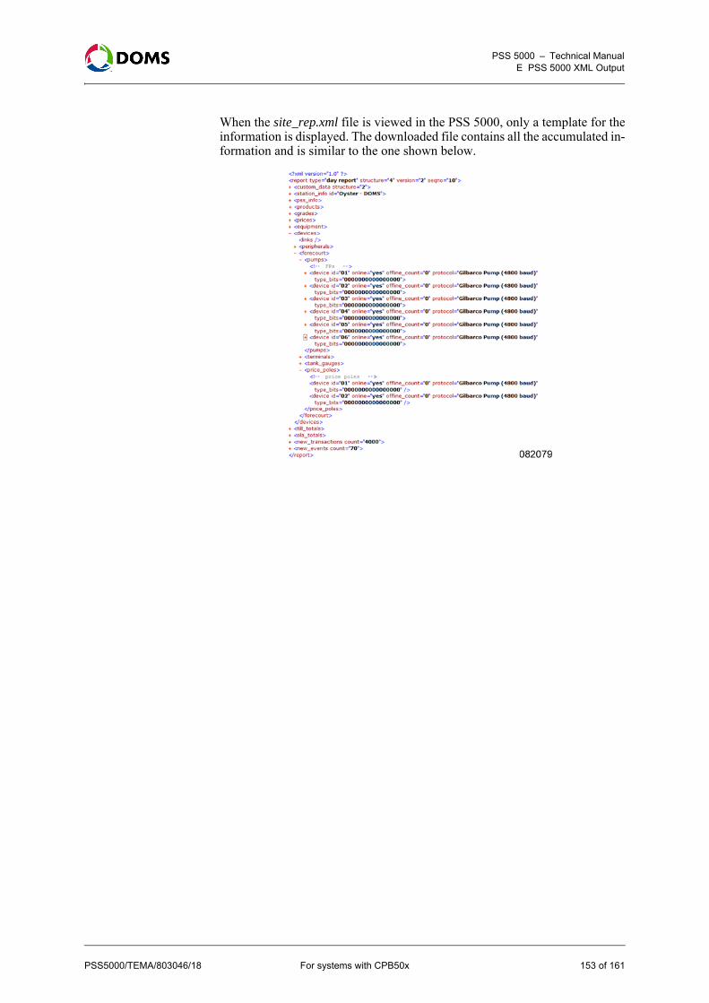
PSS 5000 – Technical ManualE PSS 5000 XML Output
When the site_rep.xml file is viewed in the PSS 5000, only a template for theinformation is displayed. The downloaded file contains all the accumulated in-formation and is similar to the one shown below.
PSS5000/TEMA/803046/18 For systems with CPB50x 153 of 161
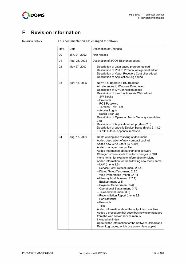
PSS 5000 – Technical ManualF Revision Information
F Revision Information
Revision history This documentation has changed as follows:
Rev. Date Description of Changes
00 Jan. 21, 2002 First release
01 Aug. 23, 2002 Description of BOOT Exchange added
02 May 27, 2003 • Description of Java based program upload• Description of Port to Protocol Assignment added• Description of Vapor Recovery Controller added• Description of Application Log added
03 April 18, 2005 • New CPU Board (CPB509) added• All references to Windows95 removed• Description of XP Connection added• Description of new functions via Web added:
– SW Blocks– Protocols– POS Password– Terminal Text Test– Access Logon– Board Error Log
• Description of Operation Mode Menu system (Menu 3.5)
• Description of Application Setup (Menu 2.5)• Description of specific Device Status (Menu 5.1.4.2)• TCP/IP Tutorial appendix removed
04 Aug. 17, 2009 • Restructuring and restyling of document• Added description of new compact cabinet• Added new CPU Board (CPB505)• Added manager user profile• Added information about changing software• Changed screen shots to reflect changes in GUI
menu items, for example Information for Menu 1• Added information for the following new menu items:
– LAM (menu 1.5)– Service Port Protocol (menu 2.3.4)– Dialup Setup/Test (menu 2.3.6)– Web Preferences (menu 2.4.4)– Memory Module (menu 2.7.1)– Backup (menu 2.8)– Payment Server (menu 3.4)– Operational Status (menu 3.7)– TeleTerminal (menu 3.8)– Reconciliation Report (menu 3.9)– Port Statistics– Protocols– Test
• Added information about the output from xml files• Added a procedure that describes how to print pages
from the web server service menus.• Included an index• Updated the information for the Software Upload and
Reset Log pages, which use a new Java applet
PSS5000/TEMA/803046/18 For systems with CPB50x 154 of 161

PSS 5000 – Technical ManualF Revision Information
05 Nov. 30, 2010 • Updated HIM information• Only the admin user is able to change Passwords• Only the admin user is valid on CPBs without LAM• Added Wet Stock Setup option in Menu 2.5• Updated the description for Fallback Mode• Improved the data in the Operational Status window• Minor text changes
06 July 2, 2012 • Updated PSS License Management information and screen
• Included more details about wet stock setup• Updated software uploads to PSS using FTP clients• Updated Online List screen to illustrate POS Id
07 April 16, 2013 Updated the Protocol to Port Assignment procedures and added a new procedure to set the protocol parame-ters.
08 May 30, 2013 Updated the Protocol to Port Assignment procedures to match the removal of the Now and Later radio buttons.
09 August 21, 2013 Updated the Application Setup information with Totals Setup option.
10 November 1, 2013
• Updated Protocol to Port Assignment options with port 99
• Updated Online List with port 99
11 Jan. 3, 2014 Removed Extension port (31) option from CPB specs.
12 Jan. 21, 2014 • Added description of Serial Server functionality• Updated user access rights
13 Jun. 23, 2014 • Added details about Service Port NULL modem ca-ble connections.
• Updated sections W.7.2 and W.7.5 with new LSP displays.
14 Oct. 31, 2014 • Updated the Setting the Protocol Parameter Values procedure.
• Added details about LSP displays during a startup cycle.
15 Feb. 17, 2015 • Updated the CPB specifications table.• Updated the activating checking procedures W.7.1 –
W.7.5.• Added activating checking procedures for W.7.6 &
W.7.7.
16 Mar. 17, 2015 • Updated the File Formats with the extended format.• New procedure to view/verify software installed on
PSS.• Updated the characters required for PSS passwords.• Updated the valid range for Datalink Timeout.
17 May 17, 2016 • Updated the Forecourt Controller Setup procedure by adding control of Local Service Panel (LSP).
• Changed the minimum number of characters re-quired in a password to 3.
18 Dec. 30, 2016 Added text "For systems with CPB50x" to the front page and page footers.
Rev. Date Description of Changes
PSS5000/TEMA/803046/18 For systems with CPB50x 155 of 161

PSS 5000 – Technical ManualIndex
Index
AAccess log
view using local service panel 103view using web service pages 102
Access Log menudescription 102
Adminuser rights 53
ADT Moduleterm 148
Appl LEDfunctions 23
Application information filedetails 146
Application logview file 102view using local service panel 102
Application Log menudescription 101
Application programdescription 19location 18view version with local service panel 31view version with web service pages 30
Application setupchange Forecourt Control Setup 58change Protocol Specific Setup 59change with web service pages 57
applog.txt fileview 102
Arrow buttonsfunctions 23
BBackup
create setup.ini file 67description 66
bel.txt fileview 103
Board Error Logmenu description 103view using web service pages 103
Board error logview log file 103
Board Info menuproduction information and sealing switch
status 31Board Upload Log
file details 141location 18
BOOTnotice before upload 61
Boot information filedetails 144
Boot LED
functions 23Boot program
description 18location 18view version with local service panel 31view version with web service pages 30
bul.txt fileview 98
CChecking devices
activate SECTEL using local service panel 123activate using web service menu pages 121display errors using local service panel 122LAM code errors using local service panel 123RTC errors using local service panel 124Trans Log Read Errors using local service
panel 126TRANS MEMORY ERR using local service
panel 125Trans Read using local service panel 125
Checking Devices menudescription 121list of sub-menus 121
Communication menulist of sub-menus 104
Communication Setup menulist of sub-menus 43
config.xml filedetails 151
Connectionscreating a null modem 138description for Ethernet 135description for service port 135set up properties 138
CPU BoardLED functions 23
DDatalink Timeout
view or change with local service panel 49view or change with web service pages 48
Date & Timedescription 42view or change with local service panel 42view or change with web service pages 42
DCB Moduleterm 148
Device errorslist recent errors using web service pages 87view specific errors using local service panel 88view specific errors using web service pages 87
Device Errors menudescription 87
156 of 161 For systems with CPB50x PSS5000/TEMA/803046/18

PSS 5000 – Technical ManualIndex
Device statusview VRM status using web service pages 90, 92,
93Device Status menu
description 90Device test
view terminal text text using web service pages 96Device Test menu
description for terminal text test 95description for VRC 93
DiagnosticsEthernet statistics 104port statistics 105protocols 106start peep 107
Diagnostics menulist of sub-menus 85
Dialup Setup/Testdescription menu parameters 50view or change settings with web service
pages 50DMB Module
term 148DMB module
illustration 14DMB Port
term 148DSB Module
term 148DSB module
illustration 14DSB Port
term 148
EEmergency access
use default passwords 55use password for a day 55using default passwords 55
Entry point to service menususing local service panel 24
Error messageson service panel display 25
Errors menudescription 110
Ethernet connectioncable types 135description 135
Ethernet statisticsdescription 104view using web service pages 104
FFallback Mode
description 69set using local service panel 70set using web service pages 70
File formatsbanknote transaction log 132, 133card transaction log 130, 131
recent transactions 129, 130upload log 133
Forecourt Control SetupPSS License Management 58Totals Setup 58Wet Stock Setup 58
Forecourt Devices menulist of sub-menus 85
FTP serverdescription 20
Fuel transactionsmonitor 72
GGrade
term 148Grade prices
change with local service panel 71view/change using web service pages 71
Guestuser rights 53
HHardware
contents of cabinet 11description of HIMs 14list of componets 11
Hardware information filedetails 143
HIMsdescription 14illustration 14
Hostuser rights 53
IInformation menu
list of sub-menus 30Installation menu
list of sub-menus 36
LLAM
description 18location 18notice before upload 61view LAM information 35view version with local service panel 31view version with web service pages 30
LAM IDview using local service panel 115
LAM information filedetails 145
LAM parametersdescription 115view using local service panel 116view using web service pages 116
LAM version
PSS5000/TEMA/803046/18 For systems with CPB50x 157 of 161

PSS 5000 – Technical ManualIndex
view using web service pages 114LEDs
Appl 23Boot 23
Load response filedetails 142
Local service paneldisplay 24display cycles at startup 24idle menu 24navigation buttons functions 23purpose 22view program versions 31viewing data 25
Logsaccess 102board error 103payment 119reset logs 98upload log 97view access 102, 103view application 102view board error 103view master reset 99, 101view soft reset 98, 100view super master reset 100, 101
MManifolded
term 148Master reset
description 82using local service panel 82using web service pages 82
Master Reset logview using local service panel 101view using web service pages 99
MD5 Hash Code 20Memory
pss_mem1 18pss_mem2 17pss_mem3 17pss_mem4 17
Memory Moduleconfigure number of peripheral devices 65configure using setup.ini file 66description 65view details using local service panel 117view details using web service pages 117view status using web service pages 112
Memory Module menudescription 112
Memory Module Version menudescription 117
Modemdescription of connections 135
Modulesillustration of DMB 14illustration of DSB 14
NNavigation buttons
location 22Navigation panel
functions 23Network connection
description 21Null modem
description of connections 136
Ook2upload file
details 144Online devices
list using local service panel 86list using web service pages 85
Online list menudescription 85, 110
Online/Offline Event Timeview or change with web service pages 52
Operation menulist of sub-menus 69
Operation Modedescription of menu 74set 75
Operation Status menudescription 76view forecourt devices 76
PPassword
description 52Payment log
view details using web service pages 120view using local service panel 120
Payment Log menudescription 119
Payment Server menudescription 73
Peep menudescription 106start peeper 107
Peripheral configurationchange setup.ini file using FTP 65of memory modules 65
Peripheral devicesdescription of memory module 65
Peripherals errorsview recent using web service pages 111view specific device types using web service
pages 111, 113Peripherals menu
list of sub-menus 109Peripherals online list
view those currently connected 110Port
term 148Port Statistics menu
description 104
158 of 161 For systems with CPB50x PSS5000/TEMA/803046/18

PSS 5000 – Technical ManualIndex
view using web service pages 105POS
user rights 53POS Password menu
change using web service pages 56description 56
POS terminalsusing Ethernet 9using serial POS driver 8
Price Pole Test menudescription 88start using local service panel 90start using web service pages 89update prices using web service pages 89
Printweb service menu page 26
Procotols menuview using web service pages 106
Productterm 149
Production informationboard information 31view with local service panel 32view with web service pages 32
Program Versionsinformation files in virtual file system 31view with local service panel 31view with web service pages 30
Program versions menudescription 30
PROMpss_mem1 18
Protocolterm 149
Protocol to port assignmentadd to port 41 with web service pages 39add to port 99 with web service pages 39configure with web service pages 37description 36edit with web service pages 38limitations 41overview 36remove with web service pages 39set protocol parameter values 40
Protocols menudescription 105
PSSusing Ethernet and serial interfaces 10
PSS 5000external label 12term 149voltage rating 12
PSS License Managementsetup 58
Pss_dev catalogdescription 16
Pss_mem catalogdescription 16
Pss_proc catalogdescription 16
RRAM
pss_mem2 17pss_mem3 17pss_mem4 17
Recent transactionfile format 129, 130
Recent transaction dataview using local service panel 119
Reconcilation Report menudescription 77
Reconcilation Reportsparameters 78veiwing 80
Reference documentslist 149
Requirementsdescription of browser 135description of PC 135
Resetmaster 82soft 81super master 83
Reset Logs menudescription 98
Reset menulist of sub-menus 81
Restoresetup.ini file 67
SSealing switch menu
description 33Sealing switch status
view with local service panel 34view with web service pages 33
Serial numberPSS 5000 12
Serial serverport connection 21
Serviceuser rights 53
Service menusaccess methods 22
Service panel displayerror messages 25
Service portdescription of connection 135
Service Port Protocolview or change with local service panel 49
Service Port Setupdescription of menu 47view or change with local service panel 47view or change with web service pages 47
Setup.ini fileconfigure memory module 66create backup 67restore 67
Site Name see System ID
PSS5000/TEMA/803046/18 For systems with CPB50x 159 of 161

PSS 5000 – Technical ManualIndex
Site Number see System ID
site_rep.xml filedetails 152
site_sta.xml filedetails 151
Soft resetdescription 81using local service panel 81using web service pages 81
Soft Reset logview using local service panel 100view using web service pages 98
SoftwareApplication Program 19Boot Program 18changing in PSS 5000 28components 16FTP connection to PSS 19, 20FTP server description 20important notice about BOOT 61important notice about LAM 61LAM 18memory structure on CPB 17network connection description 21pss_mem catalog description 16pss_mem1 18pss_mem2 17pss_mem3 17pss_mem4 17pss_proc catalog description 16serial server description 21system catalog descriptions 16upload using FTP 64upload with local service panel 63upload with web service pages 61virtual file system structure 16web browser versions 20web server 20
Software changesdescription 27
Software components 18Software Upload
description 60methods 60
Specificationsfor PSS 5000 cabinets 12for PSS 5000 CPU Board 13
SRDterm 149
Statisticscommunication ports 105Ethernet 104
Super master resetdescription 83using local service panel 83using web service pages 83
Super Master Reset logview using local service panel 101view using web service pages 100
Supported protocolsview with web service pages 35
SW Blocksview with web service pages 34
System IDchange ID with web service pages 56
System Logs menulist of sub-menus 97
System Profile menulist of sub-menus 52
System setup filedetails 140
TTank
term 149Tank Gauge System
term 149TCP/IP setup
description of menu and parameters 44view or change parameters with local service
panel 45view or change parameters with web service
pages 45view the MAC address of the Ethernet module with
local service panel 46Terminal Text test
description 95Test menu
list of sub-menus 109TGS
term 149Totals Setup 58Transaction log 73
file format 130, 131, 132, 133Transactions
log 73monitor 72
UUpload log
file format 133view details using local service panel 118view upload log file 98view using local service panel 97view using web service pages 97, 118
Upload Log menudescription 97
Upload logsdescription 118
Use password for a dayfor emergency access 55
User passwordchange to default passwords with local service
panel 55change with web service pages 53
User rightsadmin 53guest 53host 53POS 53service 53
160 of 161 For systems with CPB50x PSS5000/TEMA/803046/18

PSS 5000 – Technical ManualIndex
vrc 53Users
access rights 52list of 52
VVirtual file system
catalogs 16list of significant files 140structure 16
VRCuser rights 53
VRC testdescription 93
WW & M menu
list of sub-menus 114W&M
description 114Web browser
FTP connection to PSS 19, 20Web Preferences menu
change settings 57description 57
Web server 20recommended browser versions 20
Web Service pagestartup page 26view program versions 30
Wet Stock Setup 58
Xxml files
config.xml 151example 150save 150site_rep.xml 152site_sta.xml 151viewing 150
PSS5000/TEMA/803046/18 For systems with CPB50x 161 of 161


![PSS 5000, Hardware Configuration Guide - assets.gilbarco.euassets.gilbarco.eu/PSS5000_HW_Configuration_Guide-804473-17[1].pdfMake a list of the types and numbers of devices on the](https://static.fdocuments.us/doc/165x107/60fd5692481c5c2a143caaa2/pss-5000-hardware-configuration-guide-1pdf-make-a-list-of-the-types-and-numbers.jpg)
![PSS 5000, Hardware Configuration Guide - Gilbarcoassets.gilbarco.eu/PSS5000_HW_Configuration_Guide-804473-17[1].pdf · PSS5000/CONF/804473/17 3 of 45 PSS 5000 – Hardware Configuration](https://static.fdocuments.us/doc/165x107/5a8043a47f8b9aa24f8c4d1b/pss-5000-hardware-configuration-guide-1pdfpss5000conf80447317-3-of-45-pss.jpg)