PSR Stud Designer User Instructions Overview Getting Started Data ...
12
Version 1.0.0.1 Page 1 June 30, 2012 PSR Stud Designer User Instructions Overview Nelson Stud’s PSR Stud Designer provides the user with code-compliant stud assembly designs for reinforced concrete slab-to-column connections. For more information regarding shear reinforcement, refer to ACI 318 and ACI 421.1 codes. Outputs or results of this application should not be utilized without verification of the accuracy and suitability of results by a licensed professional engineer. The developers of this application disclaim any liability arising from the usage of this application. Getting Started In order to get full access to the website and the software, you must register your company with Nelson Stud Welding, Inc. You can do so by clicking the "Create a New User Account" tab in the left column, and then following the steps to complete the registration process. Creating a New User Account Before you can register your company, you must create a new account. This consists of an e-mail address (which will be your User Name), password, and a security question with answer. The Password is very secure and must be a minimum length of 7 characters, including one non- alphanumeric character. The Security Question/Answer is a tool used if the Password is forgotten. It enables you to retrieve your password by e-mail by answering a prearranged personal question. Registration After creating a new user account, you are to click the "Continue" button which directs you to the User Profile page. You will then need to complete the resulting form with your company's information. After completion, the form will be submitted for validation and approval. Within a few days, you will be notified by email when your account has been approved. For further assistance about using the site, please click on the "Help" tab in the left column. Data Input To access the program, log in, select the “PSR Stud Designer” tab under the “Software” section on the left side of the screen view and accept the disclaimer statement. Then make the following entries:
Transcript of PSR Stud Designer User Instructions Overview Getting Started Data ...

Version 1.0.0.1 Page 1 June 30, 2012
PSR Stud Designer User Instructions
Overview
Nelson Stud’s PSR Stud Designer provides the user with code-compliant stud assembly designs
for reinforced concrete slab-to-column connections. For more information regarding shear
reinforcement, refer to ACI 318 and ACI 421.1 codes.
Outputs or results of this application should not be utilized without verification of the accuracy
and suitability of results by a licensed professional engineer. The developers of this application
disclaim any liability arising from the usage of this application.
Getting Started
In order to get full access to the website and the software, you must register your company with
Nelson Stud Welding, Inc. You can do so by clicking the "Create a New User Account" tab in
the left column, and then following the steps to complete the registration process.
Creating a New User Account
Before you can register your company, you must create a new account. This consists of an e-mail
address (which will be your User Name), password, and a security question with answer. The
Password is very secure and must be a minimum length of 7 characters, including one non-
alphanumeric character. The Security Question/Answer is a tool used if the Password is
forgotten. It enables you to retrieve your password by e-mail by answering a prearranged
personal question.
Registration
After creating a new user account, you are to click the "Continue" button which directs you to
the User Profile page. You will then need to complete the resulting form with your company's
information. After completion, the form will be submitted for validation and approval. Within a
few days, you will be notified by email when your account has been approved.
For further assistance about using the site, please click on the "Help" tab in the left column.
Data Input
To access the program, log in, select the “PSR Stud Designer” tab under the “Software” section
on the left side of the screen view and accept the disclaimer statement. Then make the following
entries:
Version 1.0.0.1 Page 2 June 30, 2012
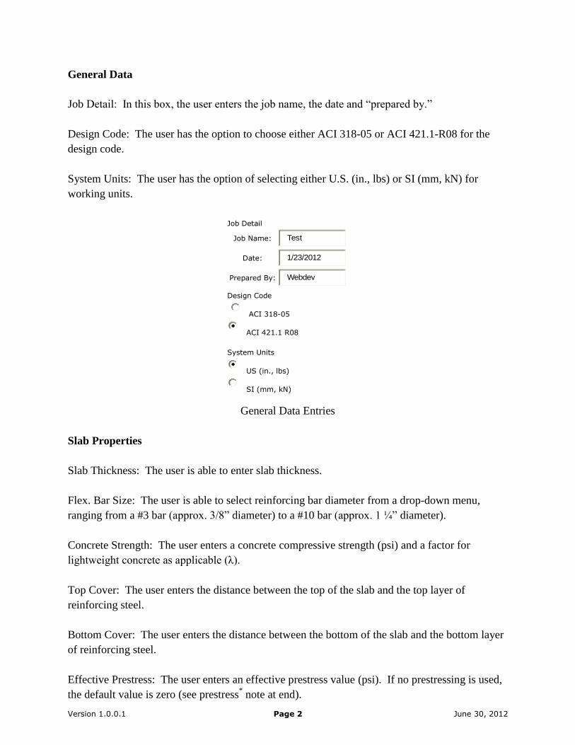
General Data
Job Detail: In this box, the user enters the job name, the date and “prepared by.”
Design Code: The user has the option to choose either ACI 318-05 or ACI 421.1-R08 for the
design code.
System Units: The user has the option of selecting either U.S. (in., lbs) or SI (mm, kN) for
working units.
Job Detail
Job Name: Test
Date: 1/23/2012
Prepared By: Webdev
Design Code
ACI 318-05
ACI 421.1 R08
System Units
US (in., lbs)
SI (mm, kN)
General Data Entries
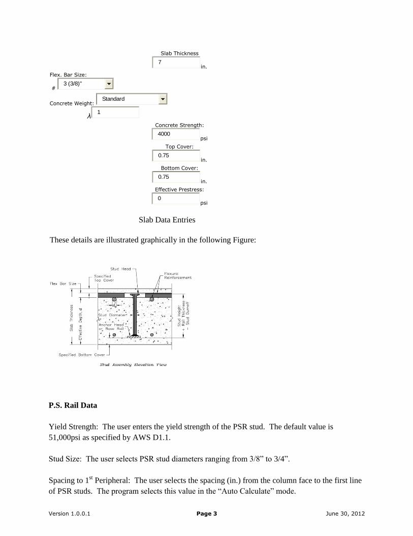
Slab Properties
Slab Thickness: The user is able to enter slab thickness.
Flex. Bar Size: The user is able to select reinforcing bar diameter from a drop-down menu,
ranging from a #3 bar (approx. 3/8” diameter) to a #10 bar (approx. 1 ¼” diameter).
Concrete Strength: The user enters a concrete compressive strength (psi) and a factor for
lightweight concrete as applicable (λ).
Top Cover: The user enters the distance between the top of the slab and the top layer of
reinforcing steel.
Bottom Cover: The user enters the distance between the bottom of the slab and the bottom layer
of reinforcing steel.
Effective Prestress: The user enters an effective prestress value (psi). If no prestressing is used,
the default value is zero (see prestress* note at end).
Version 1.0.0.1 Page 3 June 30, 2012
Slab Thickness
7in.
Flex. Bar Size:
# 3 (3/8)"
Concrete Weight: Standard
λ1
Concrete Strength:
4000psi
Top Cover:
0.75in.
Bottom Cover:
0.75in.
Effective Prestress:
0psi
Slab Data Entries
These details are illustrated graphically in the following Figure:
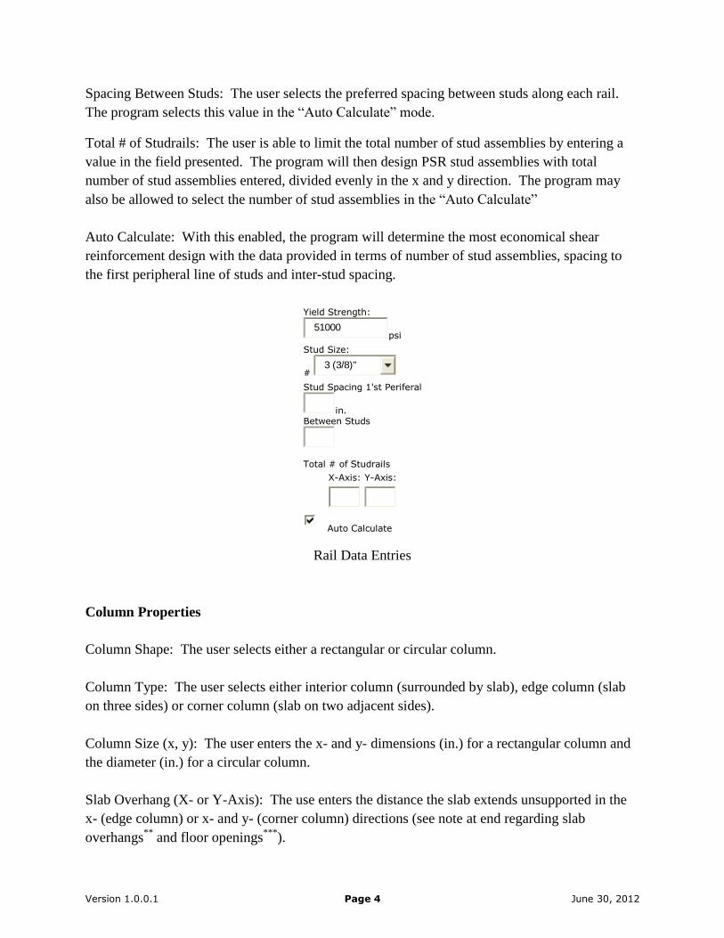
P.S. Rail Data
Yield Strength: The user enters the yield strength of the PSR stud. The default value is
51,000psi as specified by AWS D1.1.
Stud Size: The user selects PSR stud diameters ranging from 3/8” to 3/4”.
Spacing to 1st Peripheral: The user selects the spacing (in.) from the column face to the first line
of PSR studs. The program selects this value in the “Auto Calculate” mode.
Version 1.0.0.1 Page 4 June 30, 2012
Spacing Between Studs: The user selects the preferred spacing between studs along each rail.
The program selects this value in the “Auto Calculate” mode.
Total # of Studrails: The user is able to limit the total number of stud assemblies by entering a
value in the field presented. The program will then design PSR stud assemblies with total
number of stud assemblies entered, divided evenly in the x and y direction. The program may
also be allowed to select the number of stud assemblies in the “Auto Calculate”
Auto Calculate: With this enabled, the program will determine the most economical shear
reinforcement design with the data provided in terms of number of stud assemblies, spacing to
the first peripheral line of studs and inter-stud spacing.
Yield Strength:
51000psi
Stud Size:
# 3 (3/8)"
Stud Spacing 1'st Periferal
in. Between Studs
Total # of Studrails
X-Axis: Y-Axis:
Auto Calculate
Rail Data Entries
Column Properties
Column Shape: The user selects either a rectangular or circular column.
Column Type: The user selects either interior column (surrounded by slab), edge column (slab
on three sides) or corner column (slab on two adjacent sides).
Column Size (x, y): The user enters the x- and y- dimensions (in.) for a rectangular column and
the diameter (in.) for a circular column.
Slab Overhang (X- or Y-Axis): The use enters the distance the slab extends unsupported in the
x- (edge column) or x- and y- (corner column) directions (see note at end regarding slab
overhangs**
and floor openings***
).

Version 1.0.0.1 Page 5 June 30, 2012
Column Shape:
Rectangular
Column Type:
Interior
Column Size (X, Y):
12X
20in.
Slab Overhang (X-Axis):
0in.
Slab Overhang (Y-Axis):
0in.
Column Data Entries
The preceding is illustrated in the following figure showing a typical stud pattern arrangement:
Loads –
Shear Force: The user enters the total factored vertical shear force (kips) acting on the slab-to-
column connection.
Moment: The user enters the factored moment (ft-kips) applied at the column centroid in both
the x- and y-axis directions.
Shear Force:
110kips
Moment:
MuOx MuOy
0
50ft-kips
Load Data Entries
Version 1.0.0.1 Page 6 June 30, 2012
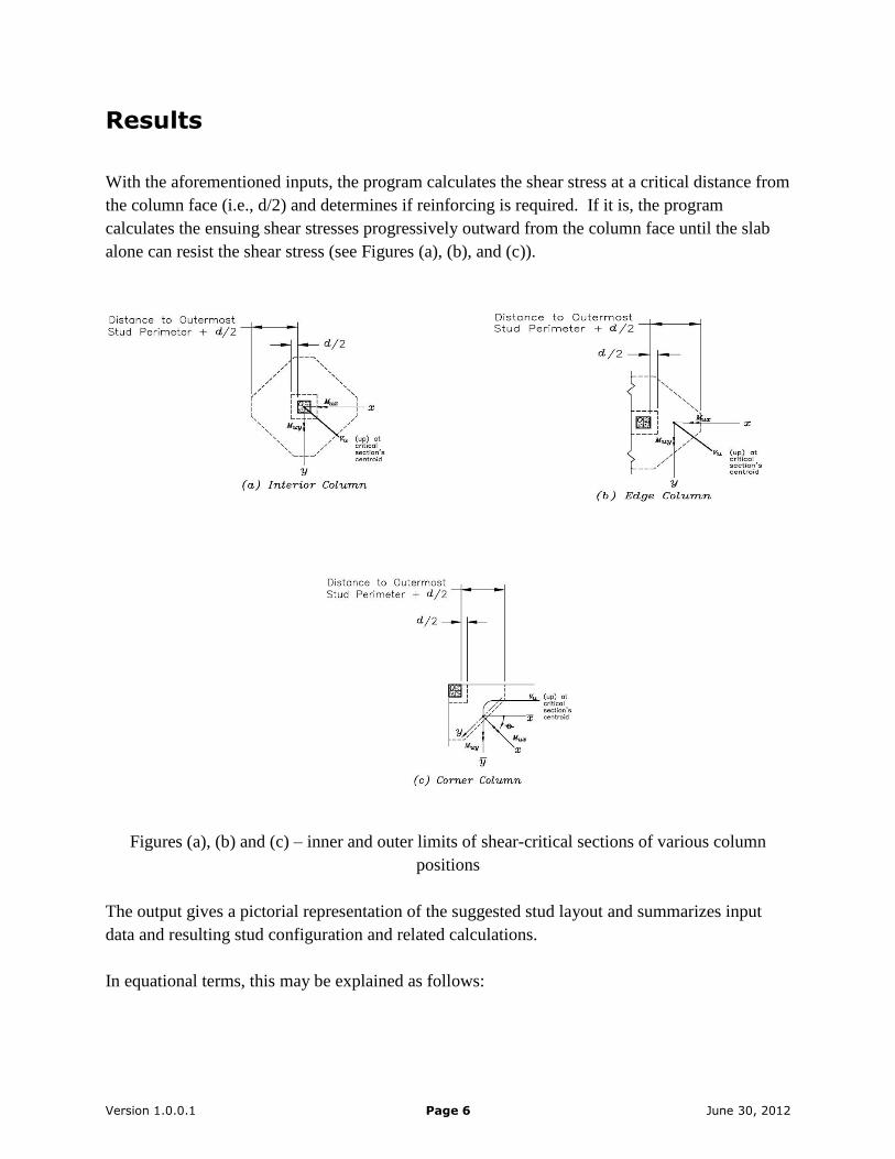
Results
With the aforementioned inputs, the program calculates the shear stress at a critical distance from
the column face (i.e., d/2) and determines if reinforcing is required. If it is, the program
calculates the ensuing shear stresses progressively outward from the column face until the slab
alone can resist the shear stress (see Figures (a), (b), and (c)).
Figures (a), (b) and (c) – inner and outer limits of shear-critical sections of various column
positions
The output gives a pictorial representation of the suggested stud layout and summarizes input
data and resulting stud configuration and related calculations.
In equational terms, this may be explained as follows:

Version 1.0.0.1 Page 7 June 30, 2012
Design requirements at critical section at (d/2) from column face and in the shear
reinforced zone -
( nu v
v) If true, shear reinforcement is required, continue design for shear reinforcement.
( nu v
v) If true, no shear reinforcing or further check is required.
( '8 cu f
v) If true, slab thickness is not adequate, increase thickness.
( '8 cu f
v) If true, slab thickness is adequate, continue design for shear reinforcement.
Nominal shear strength required at inner critical section: scn vvv
Spacing Requirements: ds 5.0 dso 5.0
Design requirements at critical section at (d/2) from outer most peripheral -
( nu v
v) If true, the extent of the shear reinforced zone is inadequate: increase # of peripherals.
( nu v
v) If true, the extent of shear-reinforced zone is adequate.
Nominal shear strength required at outer critical section: '2 cn fv
Analysis at inner critical section -
Shear stress vu = y
uyvy
x
uxvx
c
u
J
xM
J
yM
A
V= XXX psi
Factored shear stress 75.0
xxxvu XXX psi
* Select smallest nominal shear strength nv
cfvn
')4
2( =XXX psi, cfb
dv
o
sn
')2( =XXX psi or cfvn
'4 =XXX psi
nu v
v = XXX psi > XXX psi, therefore, shear reinforcement is required.
Version 1.0.0.1 Page 8 June 30, 2012
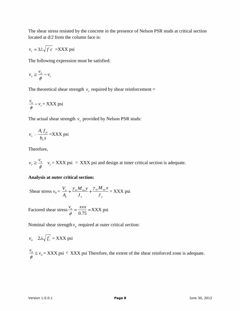
The shear stress resisted by the concrete in the presence of Nelson PSR studs at critical section
located at d/2 from the column face is:
cfvc
'3 =XXX psi
The following expression must be satisfied:
cu
s vv
v
The theoretical shear strength sv required by shear reinforcement =
cu v
v= XXX psi
The actual shear strength sv provided by Nelson PSR studs:
sb
fAv
o
ytv
s=XXX psi
Therefore,
cu
s vv
v = XXX psi XXX psi and design at inner critical section is adequate.
Analysis at outer critical section:
Shear stress vu = y
uyvy
x
uxvx
c
u
J
xM
J
yM
A
V= XXX psi
Factored shear stress75.0
xxxvu XXX psi
Nominal shear strength nv required at outer critical section:
'2 cn fv = XXX psi
nu v
v= XXX psi XXX psi Therefore, the extent of the shear reinforced zone is adequate.

Version 1.0.0.1 Page 9 June 30, 2012
The program’s output will also graphically display elevation and plan views of the suggested
stud arrangement and summarize the key design data:
Figure (d) – Stud Elevation View
Figure (e) – Stud Plan View

Version 1.0.0.1 Page 10 June 30, 2012
Suggested Product
Part Number: 102114006 Description: PSRS 3/8” X 4 15/16” MS
Input Data
Slab Properties Column Properties
Slab Thickness: 7 Column Shape: Rectangular
Flex Bar Size: 5/8 in. Column Type: Interior
Concrete Strength: 4000 psi Column Size, X(Cx) in. 12.00 in.
Top Cover: 0.75 in. Column Size, Y(Cy) in. 12.00 in.
Bottom Cover: 0.75 in. Slab Overhang, X: 0 in.
Effective Prestress: 0 psi Slab Overhang, Y: 0 in.
P.S. Rail Data Loads
Yield Strength: 51000 psi Shear Force: 100 kips
Stud Size: 3/8 in. Moment, X(Mux): 0 ft-kips
Moment, Y(Muy): 0 ft-kips
Output Data
Number of X-Axis Rails: 4 Number of Y-Axis Rails: 4
Number of Studs / Rail: 6 Stud Height: 4 15/16 in.
Anchor Strip Length: 22 5/8 in. Total Stud Rail Height: 5 in.
Anchor Strip Thickness: 3/16 in. Stud Spacing to 1st Peripheral: 1 15/16 in.
Stud Head Diameter: 1.19 in. Stud Spacing: 3 ¾ in.
Stud Head Thickness: 0.26 in. Top Cover (adjusted): 1 in.
Stud Shank Size: 3/8 in. Bottom Cover (adjusted): 1 in.
Figure (f) – Input and Output Data Summary
Input data may be zeroed or returned to defaults for a new iteration by selecting the “New
Design” button at the bottom of the output page. A given iteration of the program may be saved
for future use and reference by naming the file then selecting the “Save Design As:” button. The
output results are then stored in the “User PSR Data” tab at the main menu under the applicable
file name and the user is returned to the input section. The user may also overwrite/re-enter
certain data without completely restarting the input process by selecting the “Return to Design
Without Saving” button where the previous values will remain:
New Design Save Design as: Return to Design Without Saving
Request Quote
Output Page Actions
Finally, the user may request contact by a Nelson sales representative by selecting the “Request
Quote” button. The program will notify the affected Nelson staff member for follow-up.
Version 1.0.0.1 Page 11 June 30, 2012
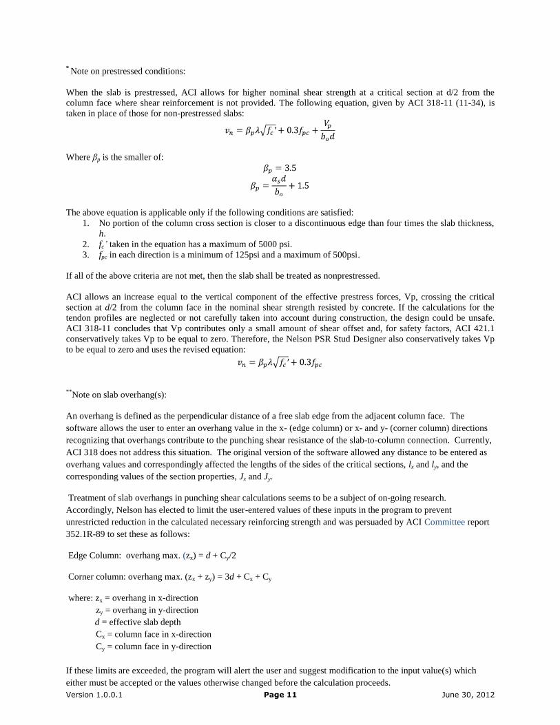
* Note on prestressed conditions:
When the slab is prestressed, ACI allows for higher nominal shear strength at a critical section at d/2 from the
column face where shear reinforcement is not provided. The following equation, given by ACI 318-11 (11-34), is
taken in place of those for non-prestressed slabs:
Where βp is the smaller of:
The above equation is applicable only if the following conditions are satisfied:
1. No portion of the column cross section is closer to a discontinuous edge than four times the slab thickness,
h.
2. fc’ taken in the equation has a maximum of 5000 psi.
3. fpc in each direction is a minimum of 125psi and a maximum of 500psi.
If all of the above criteria are not met, then the slab shall be treated as nonprestressed.
ACI allows an increase equal to the vertical component of the effective prestress forces, Vp, crossing the critical
section at d/2 from the column face in the nominal shear strength resisted by concrete. If the calculations for the
tendon profiles are neglected or not carefully taken into account during construction, the design could be unsafe.
ACI 318-11 concludes that Vp contributes only a small amount of shear offset and, for safety factors, ACI 421.1
conservatively takes Vp to be equal to zero. Therefore, the Nelson PSR Stud Designer also conservatively takes Vp
to be equal to zero and uses the revised equation:
**
Note on slab overhang(s):
An overhang is defined as the perpendicular distance of a free slab edge from the adjacent column face. The
software allows the user to enter an overhang value in the x- (edge column) or x- and y- (corner column) directions
recognizing that overhangs contribute to the punching shear resistance of the slab-to-column connection. Currently,
ACI 318 does not address this situation. The original version of the software allowed any distance to be entered as
overhang values and correspondingly affected the lengths of the sides of the critical sections, lx and ly, and the
corresponding values of the section properties, Jx and Jy.
Treatment of slab overhangs in punching shear calculations seems to be a subject of on-going research.
Accordingly, Nelson has elected to limit the user-entered values of these inputs in the program to prevent
unrestricted reduction in the calculated necessary reinforcing strength and was persuaded by ACI Committee report
352.1R-89 to set these as follows:
Edge Column: overhang max. (zx) = d + Cy/2
Corner column: overhang max. (zx + zy) = 3d + Cx + Cy
where: zx = overhang in x-direction
zy = overhang in y-direction
d = effective slab depth
Cx = column face in x-direction
Cy = column face in y-direction
If these limits are exceeded, the program will alert the user and suggest modification to the input value(s) which
either must be accepted or the values otherwise changed before the calculation proceeds.

Version 1.0.0.1 Page 12 June 30, 2012
***Note on floor openings:
ACI recognizes that openings in a floor near a load-imparting column reduce the critical section for resisting
punching shear by rendering a portion of its perimeter as “ineffective.” The PSR Stud Designer program does not
currently model this condition and, therefore, additional analysis should be performed in such a situation to ensure
adequate design (see ACI 318-11, section 11.11.6).