PSP 608 MultiDelay
47
PSP 608 MULTIDELAY 8-Tap Multimode Delay Processor
-
Upload
deecyde-dubz -
Category
Documents
-
view
61 -
download
1
description
manual of PSP 608 MultiDelay
Transcript of PSP 608 MultiDelay
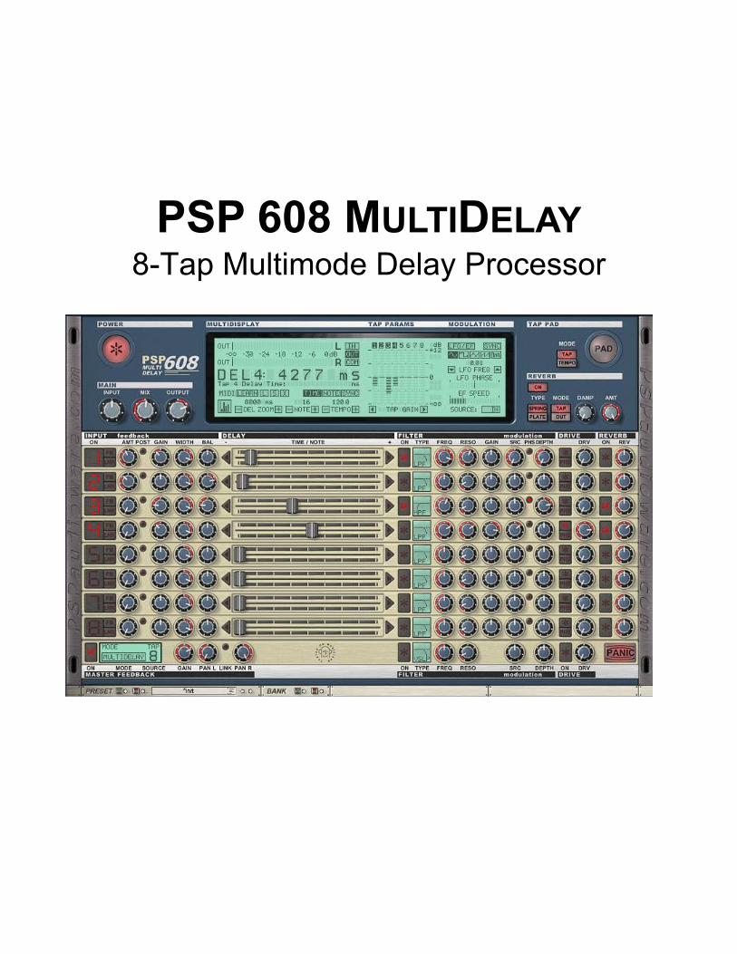
PSP 608 MULTIDELAY 8-Tap Multimode Delay Processor
By using this software you agree to the terms of any license agreement accompanying it. “PSP”, the PSP logo, and “It’s the sound that counts!” are trademarks of PSPaudioware.com. “VST” is a trademark of Steinberg Soft – und Hardware GmbH. All other trademarks are the property of their respective owners. © 2005 PSPaudioware.com s.c.
___________________________________________________________________ PSP 608 MULTIDELAY Operation Manual 2
Acknowledgements
Programming and Design: Piotr Dmuchowski Additional Algorithms and Assistance: Hubert Pietrzykowski, Mateusz Wozniak Graphics: Piotr Dmuchowski, Dariusz Ostojski Product Manager: Antoni Ozynski Documentation: Orren Merton Beta Testing: Joachim Krukowski, Chris Landon, Joerg Huettner, Hans Van Even, Mat Jarvis, Barry Wood, Thorsten Puttenat, Hiroaki Honshuku, Devon Brent, Geert Thirry
We would like to offer our very special thanks to Orren Merton for the user manual and to the creators of the very inspiring and exciting patches included with the PSP 608:
• Hans Van Even http://www.musicworks.fr • Joerg Huettner, http://www.joerg-huettner.com • Joachim Krukowski, http://www.achim.wla.pl • Chris Landon, http://www.loudnoize.com • Geert Thirry
We would also like to thank all our beta testers for their bug testing, comments and opinions.
Piotr would like to offer special thanks to: Mom, daddy, sister with her family, and all my friends - especially those from Institute of Electrical Apparatus of Technical University of Lodz and the whole DJ crew of Lodz
Finally, thanks to all our customers around the world for ideas and help in development of new plug-ins!
___________________________________________________________________ PSP 608 MULTIDELAY Operation Manual 3
End User License Agreement PREFACE: This End-User License Agreement (“EULA”) is a legal agreement between you and PSP-audioware.com s.c. (PSP) for the PSP product accompanying this EULA, which includes computer software and may include associated media, printed materials, and “online” or electronic documentation (“SOFTWARE”). By installing, copying, or using the SOFTWARE, you agree to be bound by the terms of this EULA. If you do not agree to the terms of this EULA, you may not use the SOFTWARE. The SOFTWARE is protected by copyright laws and international copyright treaties, as well as other intellectual property laws and treaties. The SOFTWARE is licensed, not sold. LICENSE: You may install and use a copy of the SOFTWARE, or in its place, any prior version for the same operating system, on a single computer. The DEMO VERSION of the SOFTWARE is NOT LICENSED FOR COMMERCIAL USE. RESTRICTIONS: You may not transfer, modify, rent, lease, loan, resell, distribute, network, electronically transmit or merge the SOFTWARE. You may not reverse engineer, decompile or disassemble the SOFTWARE, or otherwise attempt to discover the SOFTWARE source code. You are not permitted to copy the SOFTWARE or any of the accompanying documentation. COPYRIGHTS: All title and copyrights in and to the SOFTWARE (including but not limited to any images, photographs, animations, video, audio, music, text, and “applets” incorporated into the SOFTWARE ), the accompanying printed materials, and any copies of the SOFTWARE are owned by PSP. The SOFTWARE is protected by copyright laws and international treaty provisions. Unauthorized reproduction or distribution of the SOFTWARE or documentation is subject to civil and criminal penalties. DISCLAIMER OF WARRANTY: The SOFTWARE is provided “AS IS” and without warranty of any kind. The entire risk arising out of the use or performance of the SOFTWARE and documentation remains with user. To the maximum extent permitted by applicable law, PSP further disclaims all warranties, either express or implied, including, but not limited to, implied warranties of merchantability and fitness for a particular purpose, with regard to the SOFTWARE, and any accompanying hardware. To the maximum extent permitted by applicable law, in no event shall PSP be liable for any consequential, incidental, direct, indirect, special, punitive, or other damages whatsoever (including, without limitation, damages for loss of business profits, business interruption, loss of business information, or other pecuniary loss) arising out of this EULA or the use of or inability to use the SOFTWARE, even if PSP has been advised of the possibility of such damages. MISCELLANEOUS: This EULA is governed by Polish law. Should you have any questions concerning this EULA, or if you wish to contact PSP for any reason, please write to: PSPaudioware.com s.c. Dzikiej Rozy 11/8, 05-509 Jozefoslaw, Piaseczno, Poland.
___________________________________________________________________ PSP 608 MULTIDELAY Operation Manual 4
Table of Contents PSP 608 MULTIDELAY................................................................................................................. 1
Acknowledgements................................................................................................................ 3 End User License Agreement ................................................................................................ 4 Table of Contents................................................................................................................... 5 Overview ................................................................................................................................ 6
Features At A Glance ......................................................................................................... 6 Limitations of the demo version.......................................................................................... 7
Minimum System Requirements ............................................................................................ 8 Windows............................................................................................................................. 8 Macintosh ........................................................................................................................... 8
Installation Guide ................................................................................................................... 9 Windows............................................................................................................................. 9 Macintosh ......................................................................................................................... 12 Authorizing the PSP 608 .................................................................................................. 14
PSP 608 Quick Start......................................................................................................... 15 The Global Controls ............................................................................................................. 16
POWER............................................................................................................................ 16 MAIN ................................................................................................................................ 16 TAP PAD .......................................................................................................................... 16 REVERB........................................................................................................................... 17
The MULTIDISPLAY LCD.................................................................................................... 19 MULTIDISPLAY................................................................................................................ 20 TAP PARAMS .................................................................................................................. 24 GRAPH MODE................................................................................................................. 25 MODULATION ................................................................................................................. 26
The Tap Section................................................................................................................... 29 Delay Tap Signal Flow...................................................................................................... 30 Delay Tap Parameters...................................................................................................... 31
The Master Feedback Section ............................................................................................. 38 Master Feedback Mode LCD............................................................................................ 38 Master Feedback Signal Controls .................................................................................... 41
The Preset Bar..................................................................................................................... 44 Load Preset Button........................................................................................................... 44 Save Preset Button........................................................................................................... 44 Preset Window and Preset Menu ..................................................................................... 44 Preset Selection Arrows ................................................................................................... 45 Load Bank Button............................................................................................................. 45 Save Bank Button............................................................................................................. 45
Support ................................................................................................................................ 46 User Comments ................................................................................................................... 47
___________________________________________________________________ PSP 608 MULTIDELAY Operation Manual 5
Overview Thank you for purchasing the PSP 608 MultiDelay! The PSP 608 is perhaps the most fully featured delay plug-in available. We have striven to offer you a creative tool that is not only functional, but inspiring. Each tap has selectable feedback, stereo image and position, delay time, multimode filter, modulation, drive/tape saturation, and reverb. Moreover, the feedback and drive can be placed at the beginning or end of the signal chain for even more sound design options! The modulation section consists of both an LFO and Envelope follower, and the tape saturation algorithm is taken from our renowned mastering processors. And of course all this can be done at any bit depth and sample rate up to 24-bit, 192kHz, and be fully automated via MIDI and your host sequencer! As you can imagine, the PSP 608 offers so much creative potential, it is a fairly deep plug-in. We have done our best to put all the controls and parameters that you need to access directly at your fingertips, while still giving you an intuitive and user friendly dynamic GUI. If it seems complicated or even a little intimidating at first, don’t worry—you’ll get used to it fast. If we sound proud of this plug-in, it’s because we are! We’re musicians, producers, engineers, and DJs ourselves, and we just love using this plug-in - and we’re sure you will too!
Features At A Glance
• Up to 8 seconds of delay time per channel • Continuous control over the delay time in milliseconds and/or chosen quantize note • Two operation modes: Multidelay, in which each tap has its own feedback buffer; and
Multitap, in which the Master Feedback operates on one (user selectable) tap • Each tap included independent adjustment of the following: gain, stereo field width and
balance, delay time, filtering, modulation, saturation simulation and reverberation • Each tap can choose between multiple quadruple biquadratic filter types, including:
Low Pass, Band Pass, High Pass, PEAK filter and four Shelf filters • Modulation section (LFO and envelope follower) offer adjustable modulation depth of ±
3 octaves, and can be selected for filter cutoff • Tape saturation simulation with adjustable gain based on the algorithm used in our
mastering processors • Filtering module in feedback includes LP, BP, HP filter (either State Variable Filter or
Biquad) with adjustable cutoff and resonance • Vintage reverberation module for faithful simulation of spring and plate reverbs • Support for sample rates of up to 192kHz • Host and MIDI automation of all processing parameters
___________________________________________________________________ PSP 608 MULTIDELAY Operation Manual 6
Limitations of the demo version • Every 15 seconds, the delay functionality is turned off for 5 seconds • MIDI Control is disabled • Saving of MIDI assignments is disabled • Loading of MIDI assignments is disabled • Individual Preset Save and Load is disabled • Preset Bank Save and Load is disabled
___________________________________________________________________ PSP 608 MULTIDELAY Operation Manual 7
Minimum System Requirements Before installing the PSP 608 Multidelay on your Windows or Macintosh computer, please make sure your system meets these minimum requirements:
Windows • Intel Celeron 1GHz or faster processor • 256MB RAM or more • Windows XP • DX, RTAS, or VST compatible audio application
Macintosh • PowerPC G4 processor or better • 512MB RAM or more • Mac OS X 10.2 or newer • AU, RTAS, or VST compatible audio application
Please keep in mind that these CPU and RAM specifications are minimum requirements. For the best performance, you will want a faster CPU and as much RAM as possible!
___________________________________________________________________ PSP 608 MULTIDELAY Operation Manual 8
Installation Guide Installing the PSP 608 Multidelay is as easy as following the installer directions. The Windows and Mac OS X installers differ in their specific dialogs, but the basic idea is the same.
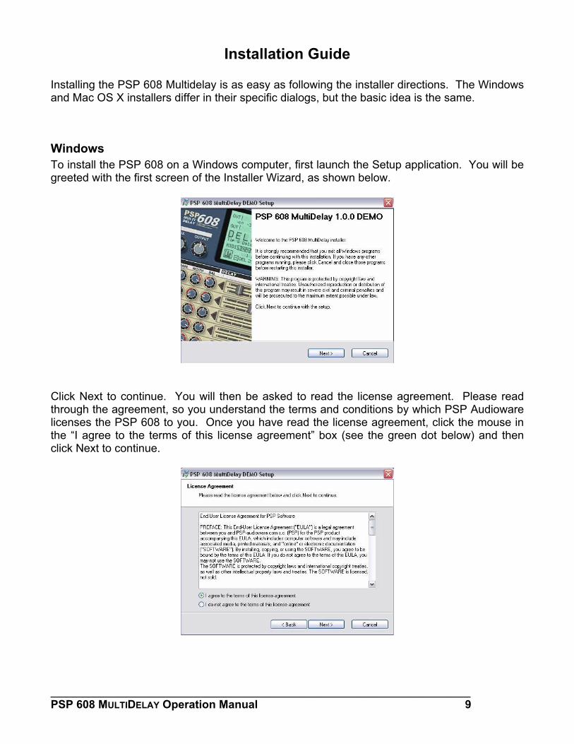
Windows To install the PSP 608 on a Windows computer, first launch the Setup application. You will be greeted with the first screen of the Installer Wizard, as shown below.
Click Next to continue. You will then be asked to read the license agreement. Please read through the agreement, so you understand the terms and conditions by which PSP Audioware licenses the PSP 608 to you. Once you have read the license agreement, click the mouse in the “I agree to the terms of this license agreement” box (see the green dot below) and then click Next to continue.
___________________________________________________________________ PSP 608 MULTIDELAY Operation Manual 9
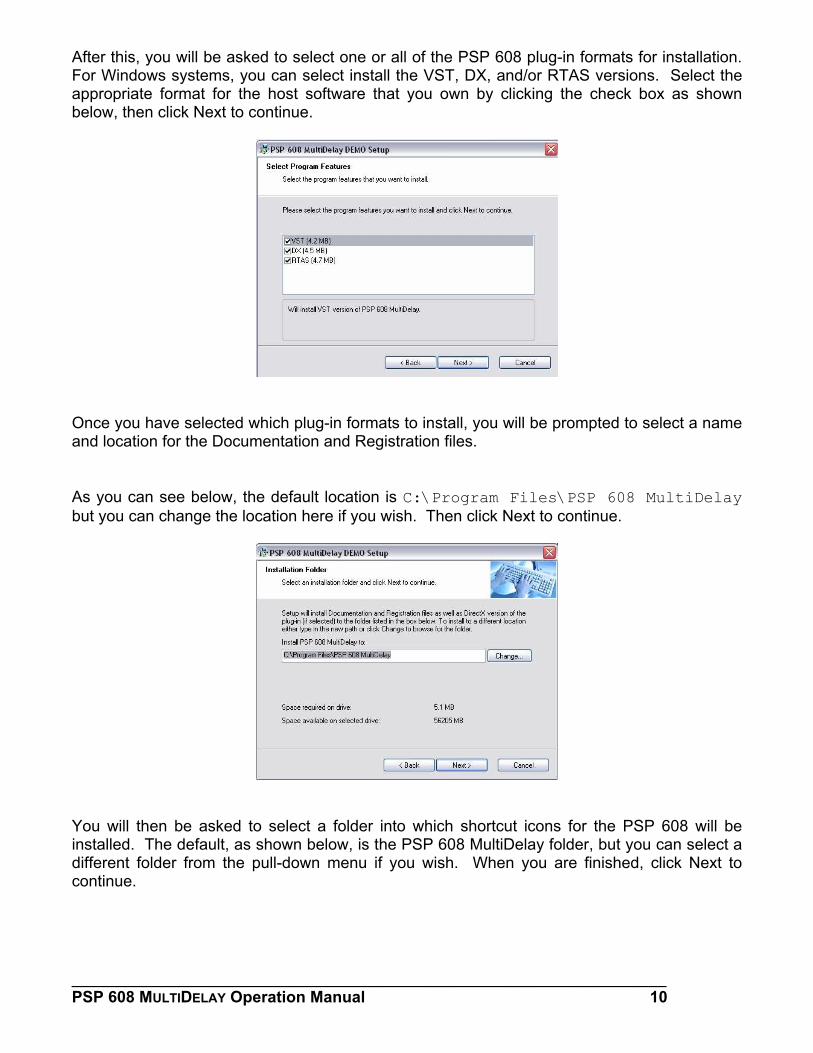
After this, you will be asked to select one or all of the PSP 608 plug-in formats for installation. For Windows systems, you can select install the VST, DX, and/or RTAS versions. Select the appropriate format for the host software that you own by clicking the check box as shown below, then click Next to continue.
Once you have selected which plug-in formats to install, you will be prompted to select a name and location for the Documentation and Registration files. As you can see below, the default location is C:\Program Files\PSP 608 MultiDelay but you can change the location here if you wish. Then click Next to continue.
You will then be asked to select a folder into which shortcut icons for the PSP 608 will be installed. The default, as shown below, is the PSP 608 MultiDelay folder, but you can select a different folder from the pull-down menu if you wish. When you are finished, click Next to continue.
___________________________________________________________________ PSP 608 MULTIDELAY Operation Manual 10
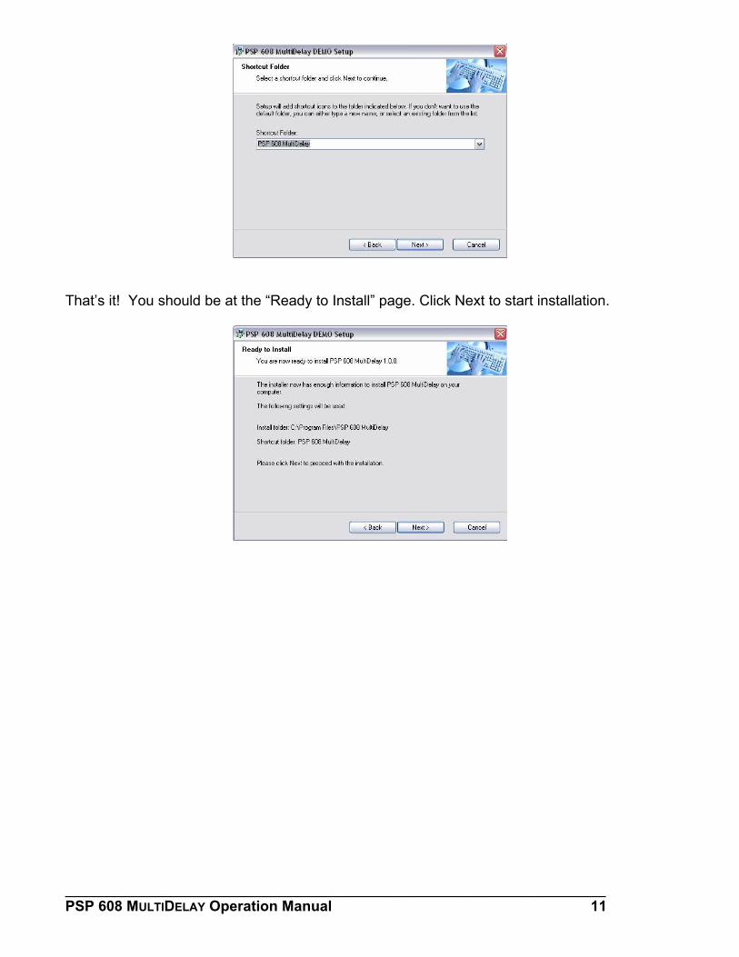
That’s it! You should be at the “Ready to Install” page. Click Next to start installation.
___________________________________________________________________ PSP 608 MULTIDELAY Operation Manual 11
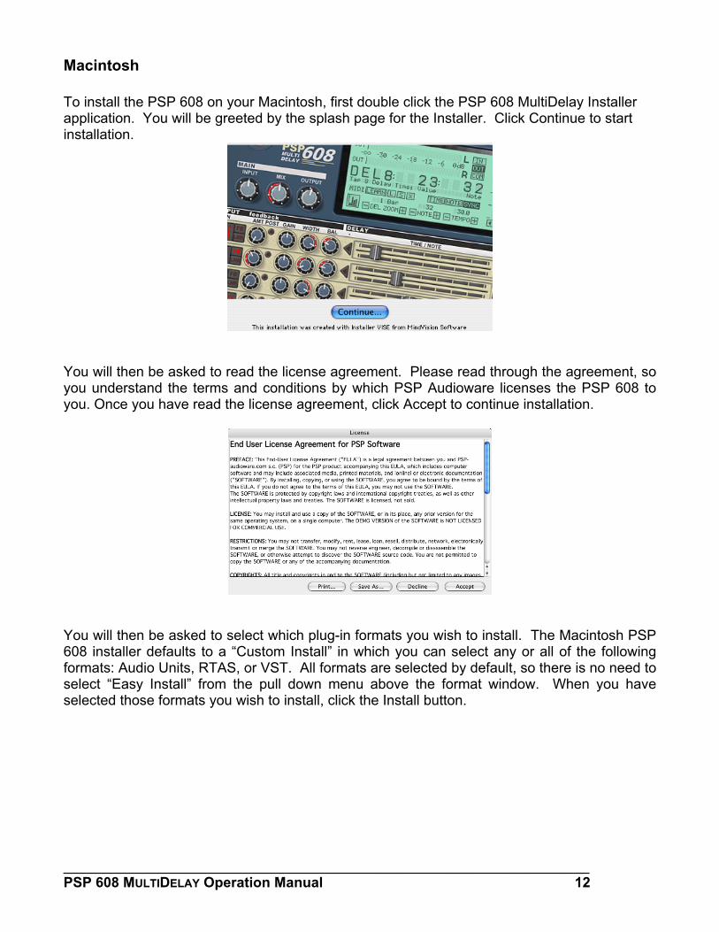
Macintosh To install the PSP 608 on your Macintosh, first double click the PSP 608 MultiDelay Installer application. You will be greeted by the splash page for the Installer. Click Continue to start installation.
You will then be asked to read the license agreement. Please read through the agreement, so you understand the terms and conditions by which PSP Audioware licenses the PSP 608 to you. Once you have read the license agreement, click Accept to continue installation.
You will then be asked to select which plug-in formats you wish to install. The Macintosh PSP 608 installer defaults to a “Custom Install” in which you can select any or all of the following formats: Audio Units, RTAS, or VST. All formats are selected by default, so there is no need to select “Easy Install” from the pull down menu above the format window. When you have selected those formats you wish to install, click the Install button.
___________________________________________________________________ PSP 608 MULTIDELAY Operation Manual 12
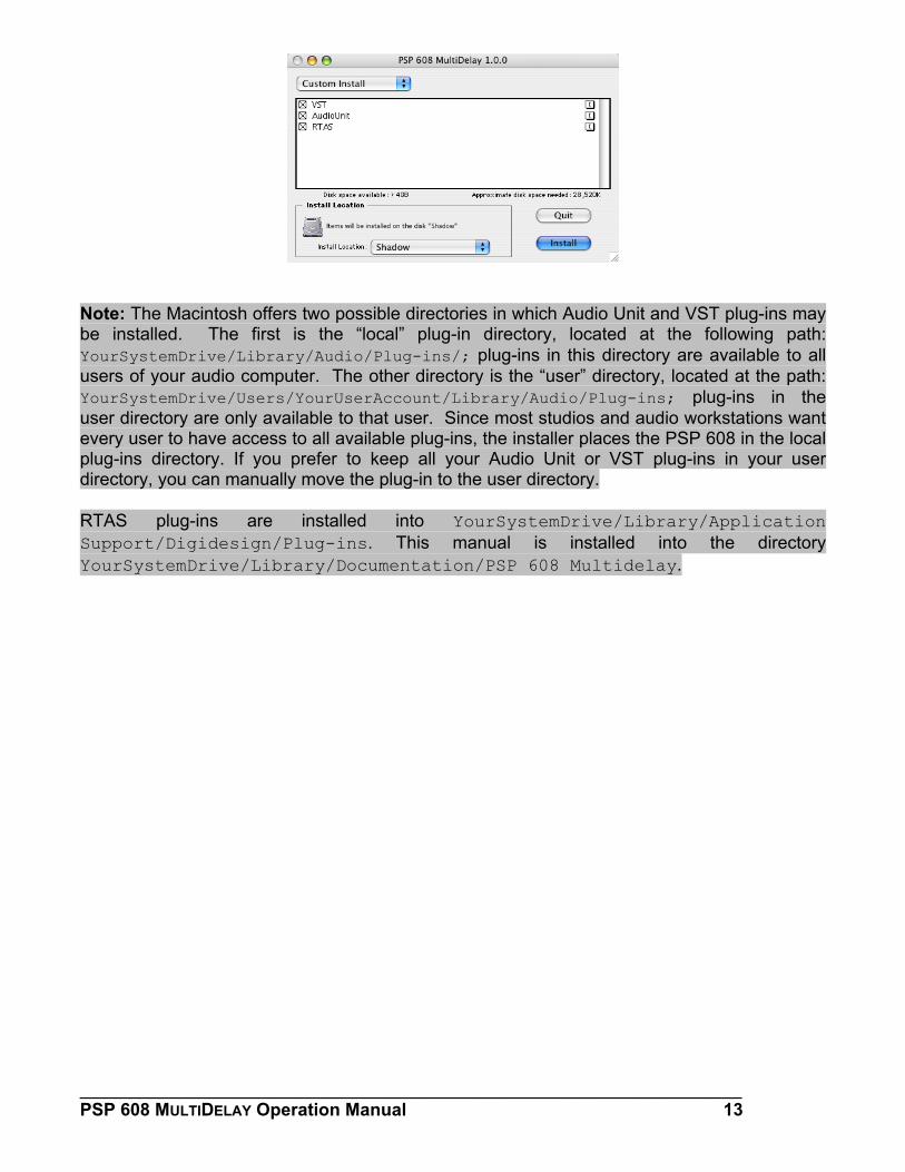
Note: The Macintosh offers two possible directories in which Audio Unit and VST plug-ins may be installed. The first is the “local” plug-in directory, located at the following path: YourSystemDrive/Library/Audio/Plug-ins/; plug-ins in this directory are available to all users of your audio computer. The other directory is the “user” directory, located at the path: YourSystemDrive/Users/YourUserAccount/Library/Audio/Plug-ins; plug-ins in the user directory are only available to that user. Since most studios and audio workstations want every user to have access to all available plug-ins, the installer places the PSP 608 in the local plug-ins directory. If you prefer to keep all your Audio Unit or VST plug-ins in your user directory, you can manually move the plug-in to the user directory. RTAS plug-ins are installed into YourSystemDrive/Library/Application Support/Digidesign/Plug-ins. This manual is installed into the directory YourSystemDrive/Library/Documentation/PSP 608 Multidelay.
___________________________________________________________________ PSP 608 MULTIDELAY Operation Manual 13
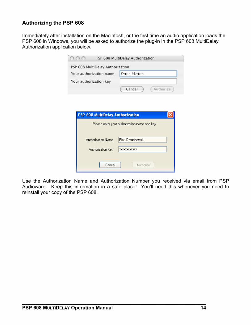
Authorizing the PSP 608 Immediately after installation on the Macintosh, or the first time an audio application loads the PSP 608 in Windows, you will be asked to authorize the plug-in in the PSP 608 MultiDelay Authorization application below.
Use the Authorization Name and Authorization Number you received via email from PSP Audioware. Keep this information in a safe place! You’ll need this whenever you need to reinstall your copy of the PSP 608.
___________________________________________________________________ PSP 608 MULTIDELAY Operation Manual 14
PSP 608 Quick Start
If you are so excited to start playing with the PSP 608 you can’t read through the manual first, here are some quick steps to get you going:
1. Instantiate the PSP 608 into an insert slot in your host DAW. 2. In the PSP 608 MAIN section, make sure the Power button is lit (ON). 3. Start playback on your host DAW. 4. Make sure you’re getting a good INPUT signal into the PSP 608 5. In the INPUT section, click the LED number “1” to turn on the first tap. 6. Adjust Tap 1’s DELAY slider until you hear the delay length you want. 7. In the INPUT section, adjust Tap 1’s feedback AMT (amount) until you hear the delay
tap trail out the way you want it to. 8. In the PSP 608 MAIN section, adjust the MIX and OUTPUT knobs until you have the
right delay level and blend with your audio. 9. Repeat this process for as many of the other taps as desired.
As you can see, getting the PSP 608 working isn’t difficult at all. But these steps, while enough to get you started, don’t reveal the true power and creative potential of this plug-in. For that, keep reading the rest of this manual! Remember: the manual is your friend! We know this plug-in has a lot of options, but don’t worry, you don’t need to remember it all at once. We designed the manual to be as comprehensive and user friendly as the plug-in itself, and the Table of Contents is very complete. Please use this as a reference whenever you need more detail. Also, look out for these shaded boxes for important notes, tips, and cautions.
___________________________________________________________________ PSP 608 MULTIDELAY Operation Manual 15
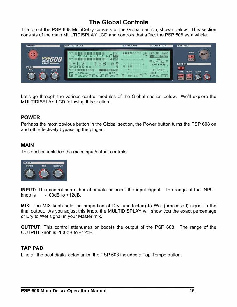
The Global Controls The top of the PSP 608 MultiDelay consists of the Global section, shown below. This section consists of the main MULTIDISPLAY LCD and controls that affect the PSP 608 as a whole.
Let’s go through the various control modules of the Global section below. We’ll explore the MULTIDISPLAY LCD following this section.
POWER Perhaps the most obvious button in the Global section, the Power button turns the PSP 608 on and off, effectively bypassing the plug-in.
MAIN This section includes the main input/output controls.
INPUT: This control can either attenuate or boost the input signal. The range of the INPUT knob is -100dB to +12dB. MIX: The MIX knob sets the proportion of Dry (unaffected) to Wet (processed) signal in the final output. As you adjust this knob, the MULTIDISPLAY will show you the exact percentage of Dry to Wet signal in your Master mix. OUTPUT: This control attenuates or boosts the output of the PSP 608. The range of the OUTPUT knob is -100dB to +12dB.
TAP PAD Like all the best digital delay units, the PSP 608 includes a Tap Tempo button.
___________________________________________________________________ PSP 608 MULTIDELAY Operation Manual 16
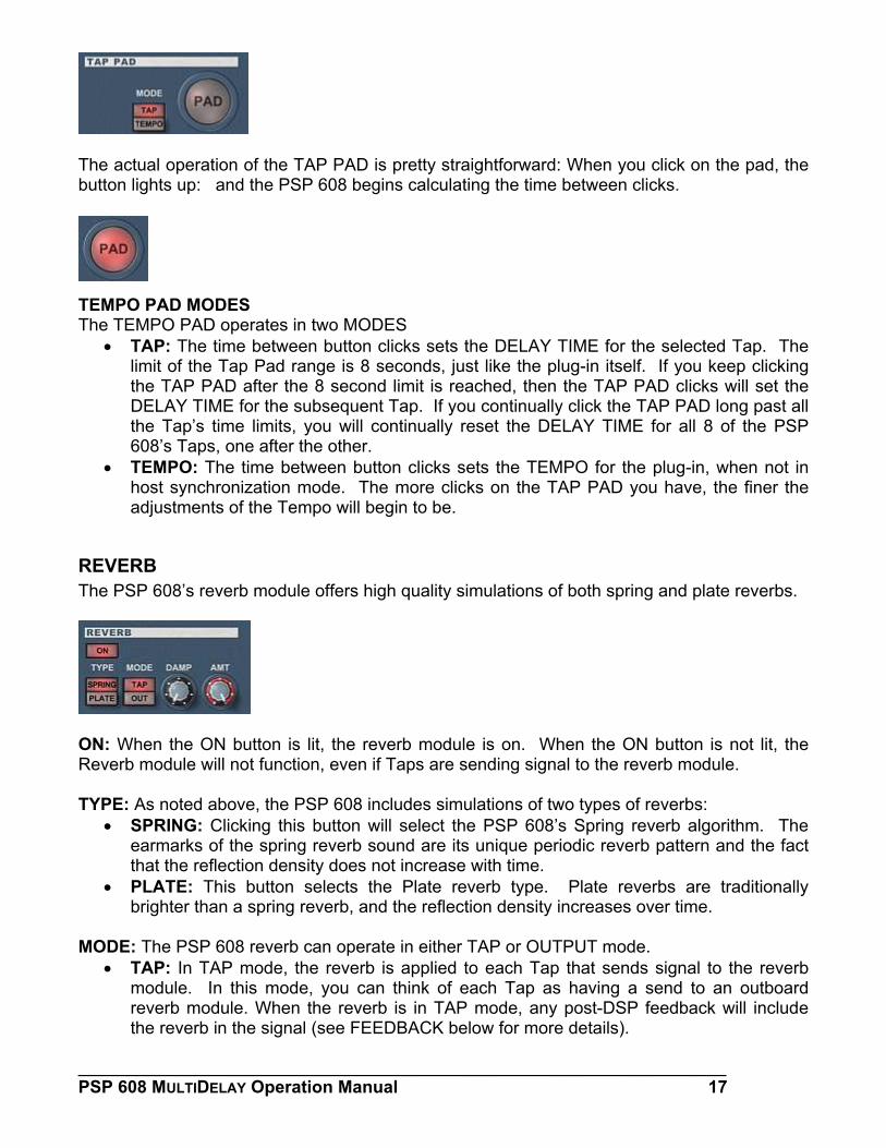
The actual operation of the TAP PAD is pretty straightforward: When you click on the pad, the button lights up: and the PSP 608 begins calculating the time between clicks.
TEMPO PAD MODES The TEMPO PAD operates in two MODES
• TAP: The time between button clicks sets the DELAY TIME for the selected Tap. The limit of the Tap Pad range is 8 seconds, just like the plug-in itself. If you keep clicking the TAP PAD after the 8 second limit is reached, then the TAP PAD clicks will set the DELAY TIME for the subsequent Tap. If you continually click the TAP PAD long past all the Tap’s time limits, you will continually reset the DELAY TIME for all 8 of the PSP 608’s Taps, one after the other.
• TEMPO: The time between button clicks sets the TEMPO for the plug-in, when not in host synchronization mode. The more clicks on the TAP PAD you have, the finer the adjustments of the Tempo will begin to be.
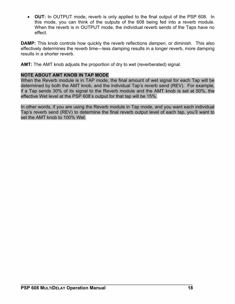
REVERB The PSP 608’s reverb module offers high quality simulations of both spring and plate reverbs.
ON: When the ON button is lit, the reverb module is on. When the ON button is not lit, the Reverb module will not function, even if Taps are sending signal to the reverb module. TYPE: As noted above, the PSP 608 includes simulations of two types of reverbs:
• SPRING: Clicking this button will select the PSP 608’s Spring reverb algorithm. The earmarks of the spring reverb sound are its unique periodic reverb pattern and the fact that the reflection density does not increase with time.
• PLATE: This button selects the Plate reverb type. Plate reverbs are traditionally brighter than a spring reverb, and the reflection density increases over time.
MODE: The PSP 608 reverb can operate in either TAP or OUTPUT mode.
• TAP: In TAP mode, the reverb is applied to each Tap that sends signal to the reverb module. In this mode, you can think of each Tap as having a send to an outboard reverb module. When the reverb is in TAP mode, any post-DSP feedback will include the reverb in the signal (see FEEDBACK below for more details).
___________________________________________________________________ PSP 608 MULTIDELAY Operation Manual 17
• OUT: In OUTPUT mode, reverb is only applied to the final output of the PSP 608. In this mode, you can think of the outputs of the 608 being fed into a reverb module. When the reverb is in OUTPUT mode, the individual reverb sends of the Taps have no effect.
DAMP: This knob controls how quickly the reverb reflections dampen, or diminish. This also effectively determines the reverb time—less damping results in a longer reverb, more damping results in a shorter reverb.
AMT: The AMT knob adjusts the proportion of dry to wet (reverberated) signal.
NOTE ABOUT AMT KNOB IN TAP MODE When the Reverb module is in TAP mode, the final amount of wet signal for each Tap will be determined by both the AMT knob, and the individual Tap’s reverb send (REV). For example, if a Tap sends 30% of its signal to the Reverb module and the AMT knob is set at 50%, the effective Wet level at the PSP 608’s output for that tap will be 15%.
In other words, if you are using the Reverb module in Tap mode, and you want each individual Tap’s reverb send (REV) to determine the final reverb output level of each tap, you’ll want to set the AMT knob to 100% Wet.
___________________________________________________________________ PSP 608 MULTIDELAY Operation Manual 18
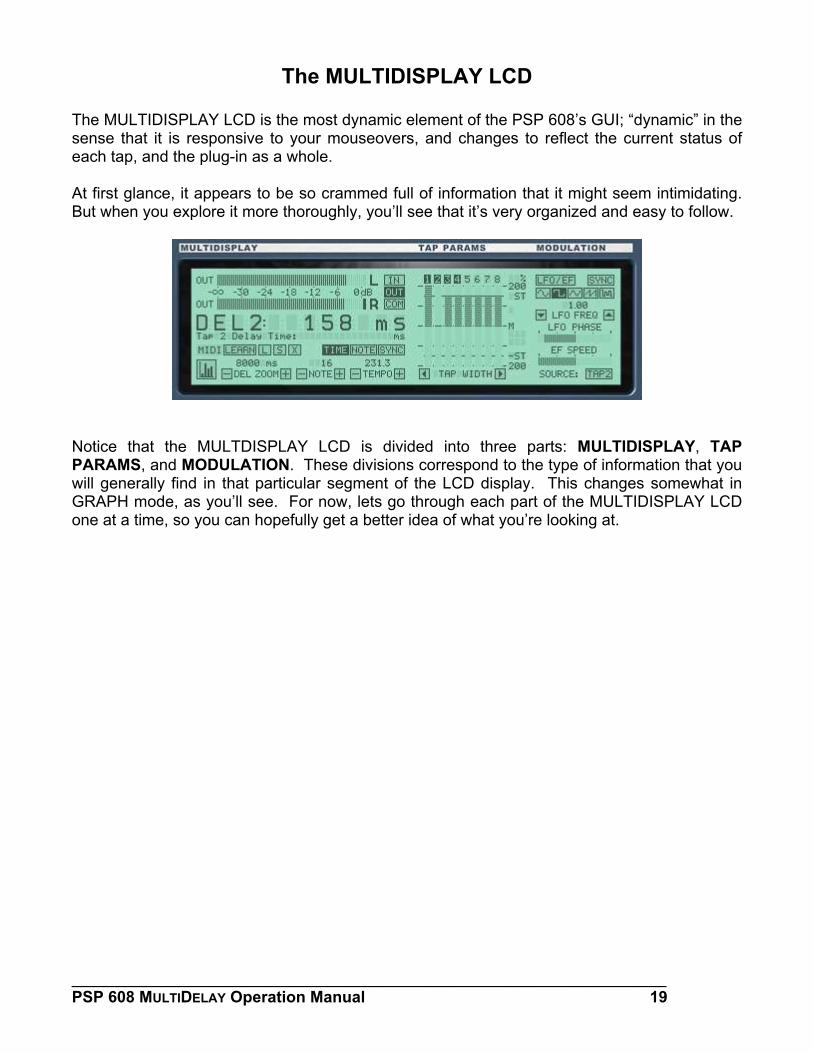
The MULTIDISPLAY LCD The MULTIDISPLAY LCD is the most dynamic element of the PSP 608’s GUI; “dynamic” in the sense that it is responsive to your mouseovers, and changes to reflect the current status of each tap, and the plug-in as a whole. At first glance, it appears to be so crammed full of information that it might seem intimidating. But when you explore it more thoroughly, you’ll see that it’s very organized and easy to follow.
Notice that the MULTDISPLAY LCD is divided into three parts: MULTIDISPLAY, TAP PARAMS, and MODULATION. These divisions correspond to the type of information that you will generally find in that particular segment of the LCD display. This changes somewhat in GRAPH mode, as you’ll see. For now, lets go through each part of the MULTIDISPLAY LCD one at a time, so you can hopefully get a better idea of what you’re looking at.
___________________________________________________________________ PSP 608 MULTIDELAY Operation Manual 19
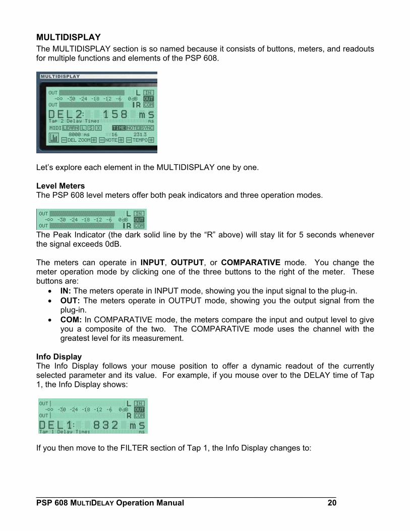
MULTIDISPLAY The MULTIDISPLAY section is so named because it consists of buttons, meters, and readouts for multiple functions and elements of the PSP 608.
Let’s explore each element in the MULTIDISPLAY one by one. Level Meters The PSP 608 level meters offer both peak indicators and three operation modes.
The Peak Indicator (the dark solid line by the “R” above) will stay lit for 5 seconds whenever the signal exceeds 0dB. The meters can operate in INPUT, OUTPUT, or COMPARATIVE mode. You change the meter operation mode by clicking one of the three buttons to the right of the meter. These buttons are:
• IN: The meters operate in INPUT mode, showing you the input signal to the plug-in. • OUT: The meters operate in OUTPUT mode, showing you the output signal from the
plug-in. • COM: In COMPARATIVE mode, the meters compare the input and output level to give
you a composite of the two. The COMPARATIVE mode uses the channel with the greatest level for its measurement.
Info Display The Info Display follows your mouse position to offer a dynamic readout of the currently selected parameter and its value. For example, if you mouse over to the DELAY time of Tap 1, the Info Display shows:
If you then move to the FILTER section of Tap 1, the Info Display changes to:
___________________________________________________________________ PSP 608 MULTIDELAY Operation Manual 20
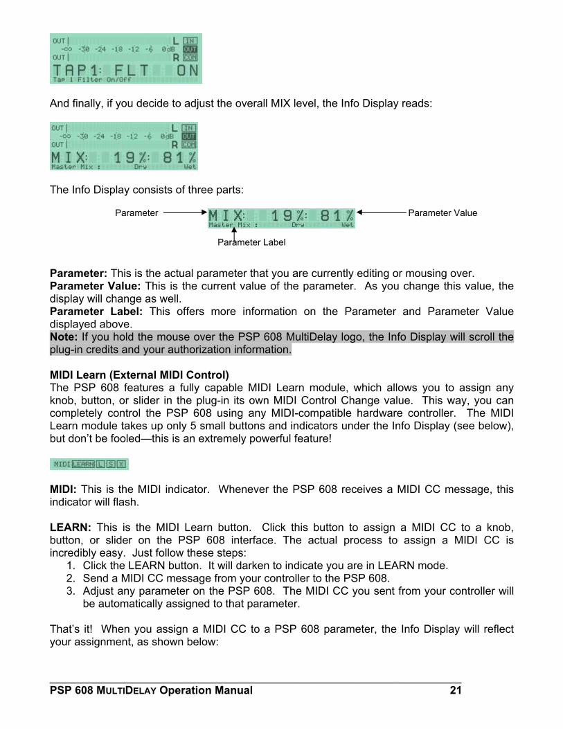
And finally, if you decide to adjust the overall MIX level, the Info Display reads:
The Info Display consists of three parts:
Parameter
Parameter Label
Parameter Value
Parameter: This is the actual parameter that you are currently editing or mousing over. Parameter Value: This is the current value of the parameter. As you change this value, the display will change as well. Parameter Label: This offers more information on the Parameter and Parameter Value displayed above. Note: If you hold the mouse over the PSP 608 MultiDelay logo, the Info Display will scroll the plug-in credits and your authorization information. MIDI Learn (External MIDI Control) The PSP 608 features a fully capable MIDI Learn module, which allows you to assign any knob, button, or slider in the plug-in its own MIDI Control Change value. This way, you can completely control the PSP 608 using any MIDI-compatible hardware controller. The MIDI Learn module takes up only 5 small buttons and indicators under the Info Display (see below), but don’t be fooled—this is an extremely powerful feature!
MIDI: This is the MIDI indicator. Whenever the PSP 608 receives a MIDI CC message, this indicator will flash. LEARN: This is the MIDI Learn button. Click this button to assign a MIDI CC to a knob, button, or slider on the PSP 608 interface. The actual process to assign a MIDI CC is incredibly easy. Just follow these steps:
1. Click the LEARN button. It will darken to indicate you are in LEARN mode. 2. Send a MIDI CC message from your controller to the PSP 608. 3. Adjust any parameter on the PSP 608. The MIDI CC you sent from your controller will
be automatically assigned to that parameter. That’s it! When you assign a MIDI CC to a PSP 608 parameter, the Info Display will reflect your assignment, as shown below:
___________________________________________________________________ PSP 608 MULTIDELAY Operation Manual 21
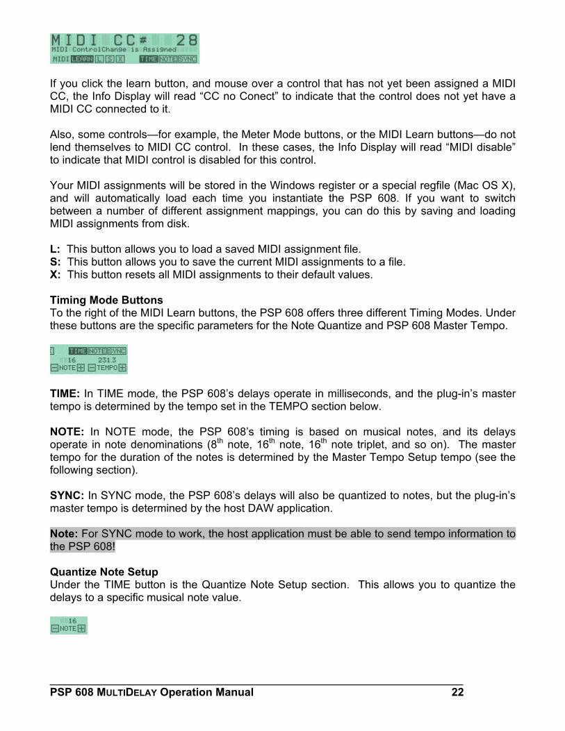
If you click the learn button, and mouse over a control that has not yet been assigned a MIDI CC, the Info Display will read “CC no Conect” to indicate that the control does not yet have a MIDI CC connected to it. Also, some controls—for example, the Meter Mode buttons, or the MIDI Learn buttons—do not lend themselves to MIDI CC control. In these cases, the Info Display will read “MIDI disable” to indicate that MIDI control is disabled for this control. Your MIDI assignments will be stored in the Windows register or a special regfile (Mac OS X), and will automatically load each time you instantiate the PSP 608. If you want to switch between a number of different assignment mappings, you can do this by saving and loading MIDI assignments from disk. L: This button allows you to load a saved MIDI assignment file. S: This button allows you to save the current MIDI assignments to a file. X: This button resets all MIDI assignments to their default values. Timing Mode Buttons To the right of the MIDI Learn buttons, the PSP 608 offers three different Timing Modes. Under these buttons are the specific parameters for the Note Quantize and PSP 608 Master Tempo.
TIME: In TIME mode, the PSP 608’s delays operate in milliseconds, and the plug-in’s master tempo is determined by the tempo set in the TEMPO section below. NOTE: In NOTE mode, the PSP 608’s timing is based on musical notes, and its delays operate in note denominations (8th note, 16th note, 16th note triplet, and so on). The master tempo for the duration of the notes is determined by the Master Tempo Setup tempo (see the following section). SYNC: In SYNC mode, the PSP 608’s delays will also be quantized to notes, but the plug-in’s master tempo is determined by the host DAW application. Note: For SYNC mode to work, the host application must be able to send tempo information to the PSP 608! Quantize Note Setup Under the TIME button is the Quantize Note Setup section. This allows you to quantize the delays to a specific musical note value.
___________________________________________________________________ PSP 608 MULTIDELAY Operation Manual 22
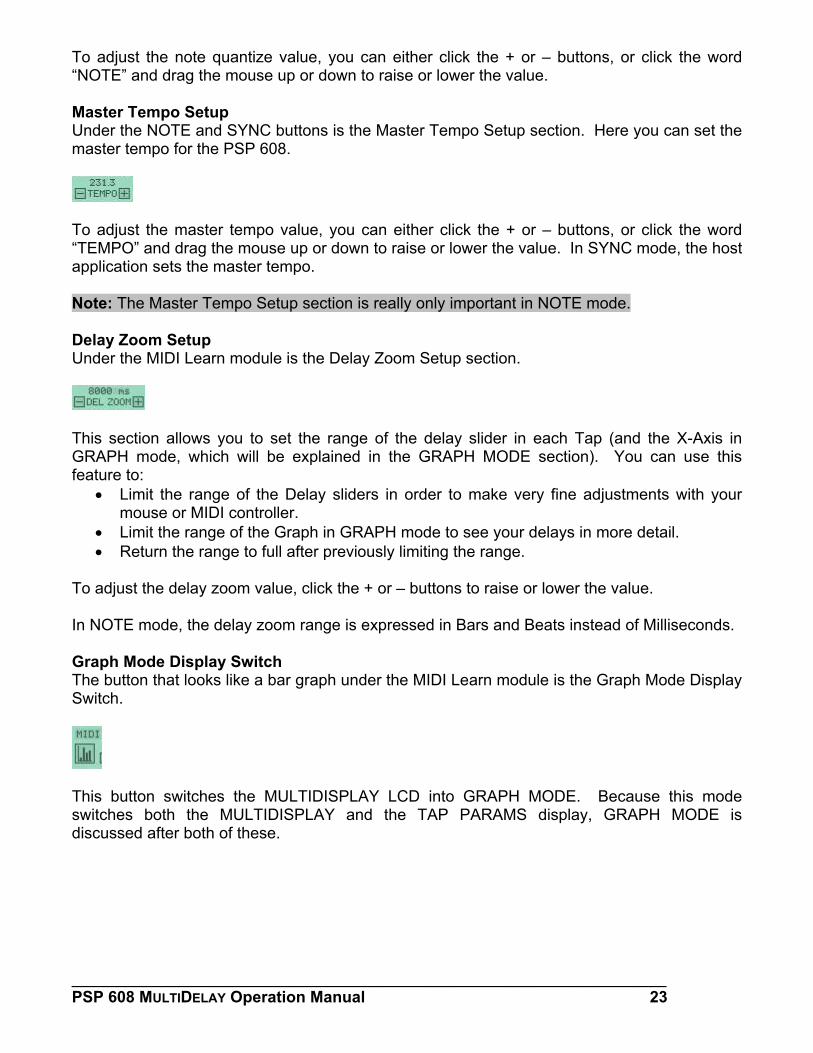
To adjust the note quantize value, you can either click the + or – buttons, or click the word “NOTE” and drag the mouse up or down to raise or lower the value. Master Tempo Setup Under the NOTE and SYNC buttons is the Master Tempo Setup section. Here you can set the master tempo for the PSP 608.
To adjust the master tempo value, you can either click the + or – buttons, or click the word “TEMPO” and drag the mouse up or down to raise or lower the value. In SYNC mode, the host application sets the master tempo. Note: The Master Tempo Setup section is really only important in NOTE mode. Delay Zoom Setup Under the MIDI Learn module is the Delay Zoom Setup section.
This section allows you to set the range of the delay slider in each Tap (and the X-Axis in GRAPH mode, which will be explained in the GRAPH MODE section). You can use this feature to:
• Limit the range of the Delay sliders in order to make very fine adjustments with your mouse or MIDI controller.
• Limit the range of the Graph in GRAPH mode to see your delays in more detail. • Return the range to full after previously limiting the range.
To adjust the delay zoom value, click the + or – buttons to raise or lower the value. In NOTE mode, the delay zoom range is expressed in Bars and Beats instead of Milliseconds. Graph Mode Display Switch The button that looks like a bar graph under the MIDI Learn module is the Graph Mode Display Switch.
This button switches the MULTIDISPLAY LCD into GRAPH MODE. Because this mode switches both the MULTIDISPLAY and the TAP PARAMS display, GRAPH MODE is discussed after both of these.
___________________________________________________________________ PSP 608 MULTIDELAY Operation Manual 23
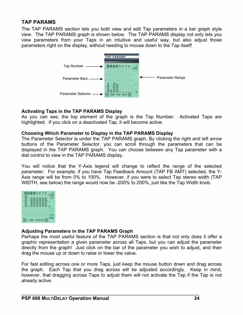
TAP PARAMS The TAP PARAMS section lets you both view and edit Tap parameters in a bar graph style view. The TAP PARAMS graph is shown below. The TAP PARAMS display not only lets you view parameters from your Taps in an intuitive and useful way, but also adjust those parameters right on the display, without needing to mouse down to the Tap itself!
Parameter Selector
Parameter Bars
Tap Number
P e
Activating Taps in the TAP PARAMS Display As you can see, the top element of the graph is the Tap Nhighlighted. If you click on a deactivated Tap, it will become activ Choosing Which Parameter to Display in the TAP PARAMS DThe Parameter Selector is under the TAP PARAMS graph. By cbuttons of the Parameter Selector, you can scroll through displayed in the TAP PARAMS graph. You can choose betwedial control to view in the TAP PARAMS display. You will notice that the Y-Axis legend will change to reflecparameter. For example, if you have Tap Feedback Amount (TAxis range will be from 0% to 100%. However, if you were to WIDTH, see below) the range would now be -200% to 200%, jus
Adjusting Parameters in the TAP PARAMS Graph Perhaps the most useful feature of the TAP PARAMS section graphic representation a given parameter across all Taps, but directly from the graph! Just click on the bar of the parameterdrag the mouse up or down to raise or lower the value. For fast editing across one or more Taps, just keep the mouse the graph. Each Tap that you drag across will be adjustedhowever, that dragging across Taps to adjust them will not actialready active.
____________________________________________________PSP 608 MULTIDELAY Operation Manual
arameter Rang
umber. Activated Taps are e.
isplay licking the right and left arrow the parameters that can be en any Tap parameter with a
t the range of the selected AP FB AMT) selected, the Y-select Tap stereo width (TAP t like the Tap Width knob.
is that not only does it offer a you can adjust the parameter you wish to adjust, and then
button down and drag across accordingly. Keep in mind, vate the Tap if the Tap is not
_______________ 24
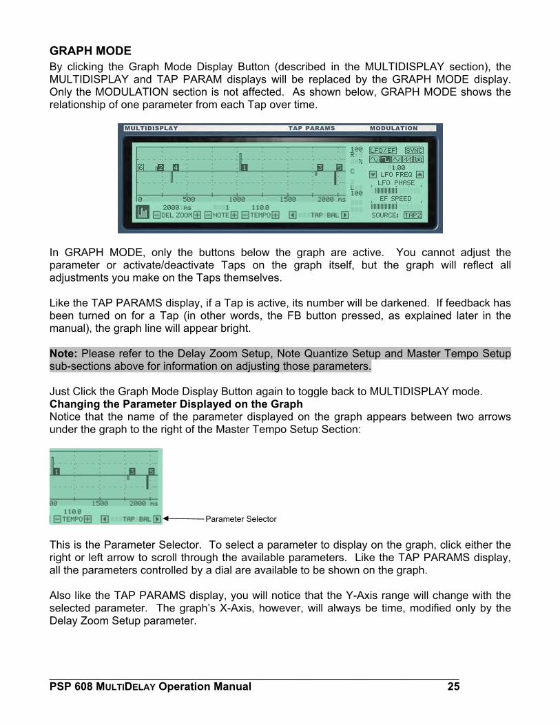
GRAPH MODE By clicking the Graph Mode Display Button (described in the MULTIDISPLAY section), the MULTIDISPLAY and TAP PARAM displays will be replaced by the GRAPH MODE display. Only the MODULATION section is not affected. As shown below, GRAPH MODE shows the relationship of one parameter from each Tap over time.
In GRAPH MODE, only the buttons below the graph are active. You cannot adjust the parameter or activate/deactivate Taps on the graph itself, but the graph will reflect all adjustments you make on the Taps themselves. Like the TAP PARAMS display, if a Tap is active, its number will be darkened. If feedback has been turned on for a Tap (in other words, the FB button pressed, as explained later in the manual), the graph line will appear bright. Note: Please refer to the Delay Zoom Setup, Note Quantize Setup and Master Tempo Setup sub-sections above for information on adjusting those parameters. Just Click the Graph Mode Display Button again to toggle back to MULTIDISPLAY mode. Changing the Parameter Displayed on the Graph Notice that the name of the parameter displayed on the graph appears between two arrows under the graph to the right of the Master Tempo Setup Section:
This is the Parameter Selector. To select a parameter to display on the graph, click either the right or left arrow to scroll through the available parameters. Like the TAP PARAMS display, all the parameters controlled by a dial are available to be shown on the graph.
Parameter Selector
Also like the TAP PARAMS display, you will notice that the Y-Axis range will change with the selected parameter. The graph’s X-Axis, however, will always be time, modified only by the Delay Zoom Setup parameter.
___________________________________________________________________ PSP 608 MULTIDELAY Operation Manual 25
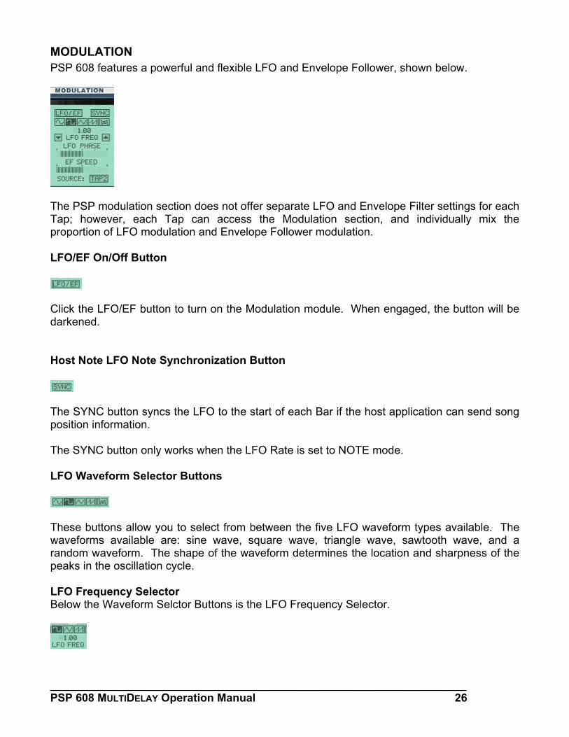
MODULATION PSP 608 features a powerful and flexible LFO and Envelope Follower, shown below.
The PSP modulation section does not offer separate LFO and Envelope Filter settings for each Tap; however, each Tap can access the Modulation section, and individually mix the proportion of LFO modulation and Envelope Follower modulation. LFO/EF On/Off Button
Click the LFO/EF button to turn on the Modulation module. When engaged, the button will be darkened. Host Note LFO Note Synchronization Button
The SYNC button syncs the LFO to the start of each Bar if the host application can send song position information. The SYNC button only works when the LFO Rate is set to NOTE mode. LFO Waveform Selector Buttons
These buttons allow you to select from between the five LFO waveform types available. The waveforms available are: sine wave, square wave, triangle wave, sawtooth wave, and a random waveform. The shape of the waveform determines the location and sharpness of the peaks in the oscillation cycle. LFO Frequency Selector Below the Waveform Selctor Buttons is the LFO Frequency Selector.
___________________________________________________________________ PSP 608 MULTIDELAY Operation Manual 26
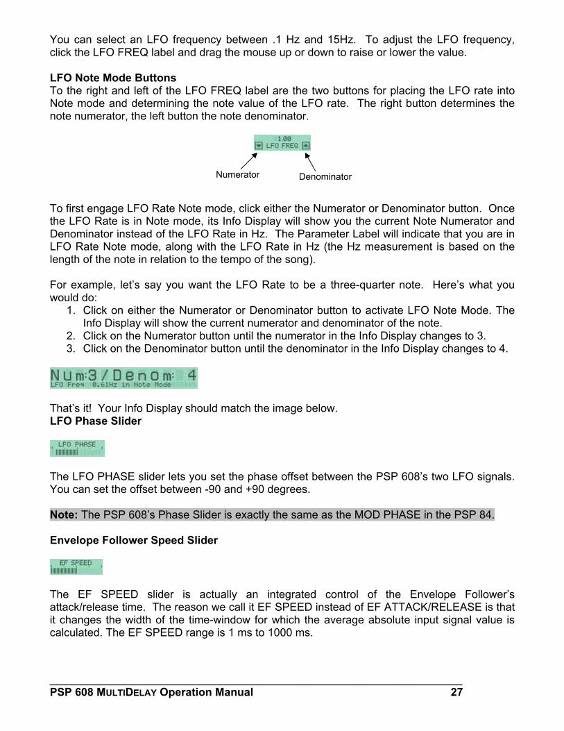
You can select an LFO frequency between .1 Hz and 15Hz. To adjust the LFO frequency, click the LFO FREQ label and drag the mouse up or down to raise or lower the value. LFO Note Mode Buttons To the right and left of the LFO FREQ label are the two buttons for placing the LFO rate into Note mode and determining the note value of the LFO rate. The right button determines the note numerator, the left button the note denominator.
To first engage LFO Rate Note mothe LFO Rate is in Note mode, itsDenominator instead of the LFO RLFO Rate Note mode, along withlength of the note in relation to the For example, let’s say you want would do:
1. Click on either the NumeraInfo Display will show the cu
2. Click on the Numerator butt3. Click on the Denominator b
That’s it! Your Info Display shouldLFO Phase Slider
The LFO PHASE slider lets you sYou can set the offset between -90 Note: The PSP 608’s Phase Slide Envelope Follower Speed Slider
The EF SPEED slider is actuattack/release time. The reason wit changes the width of the time-wcalculated. The EF SPEED range
___________________________PSP 608 MULTIDELAY Operation M
Numerator
de, click either th Info Display willate in Hz. The P
the LFO Rate in tempo of the son
the LFO Rate to
tor or Denominarrent numerator
on until the numeutton until the den
match the image
et the phase offs and +90 degree
r is exactly the sa
ally an integrae call it EF SPEEindow for which
is 1 ms to 1000 m
______________anual
Denominator
e Numerator or Denominator button. Once show you the current Note Numerator and arameter Label will indicate that you are in Hz (the Hz measurement is based on the g).
be a three-quarter note. Here’s what you
tor button to activate LFO Note Mode. The and denominator of the note. rator in the Info Display changes to 3. ominator in the Info Display changes to 4.
below.
et between the PSP 608’s two LFO signals. s.
me as the MOD PHASE in the PSP 84.
ted control of the Envelope Follower’s D instead of EF ATTACK/RELEASE is that
the average absolute input signal value is s.
__________________________ 27
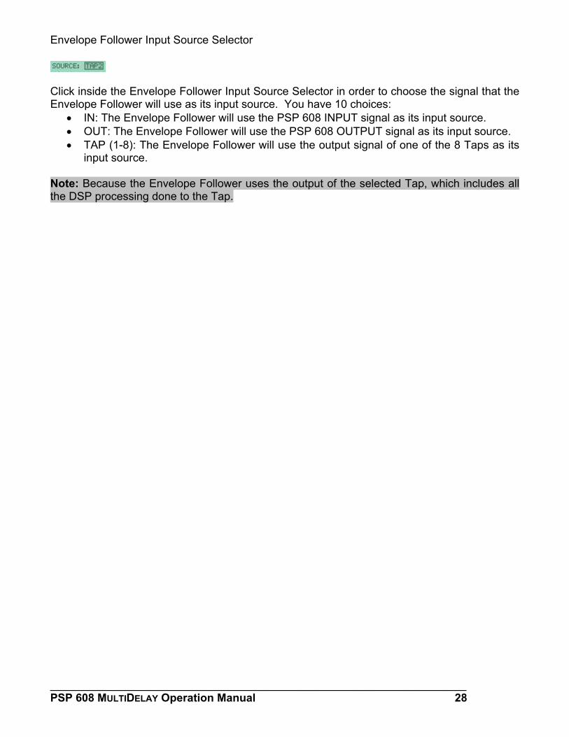
Envelope Follower Input Source Selector
Click inside the Envelope Follower Input Source Selector in order to choose the signal that the Envelope Follower will use as its input source. You have 10 choices:
• IN: The Envelope Follower will use the PSP 608 INPUT signal as its input source. • OUT: The Envelope Follower will use the PSP 608 OUTPUT signal as its input source. • TAP (1-8): The Envelope Follower will use the output signal of one of the 8 Taps as its
input source.
Note: Because the Envelope Follower uses the output of the selected Tap, which includes all the DSP processing done to the Tap.
___________________________________________________________________ PSP 608 MULTIDELAY Operation Manual 28
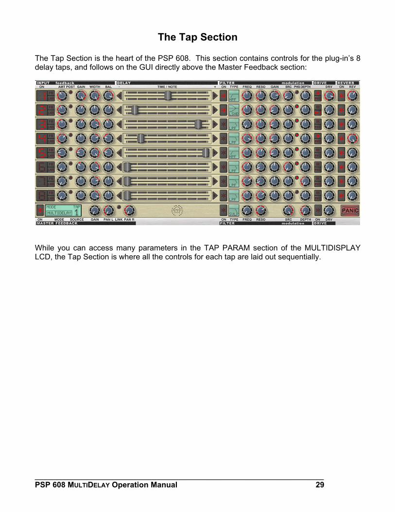
The Tap Section The Tap Section is the heart of the PSP 608. This section contains controls for the plug-in’s 8 delay taps, and follows on the GUI directly above the Master Feedback section:
While you can access many parameters in the TAP PARAM section of the MULTIDISPLAY LCD, the Tap Section is where all the controls for each tap are laid out sequentially.
___________________________________________________________________ PSP 608 MULTIDELAY Operation Manual 29
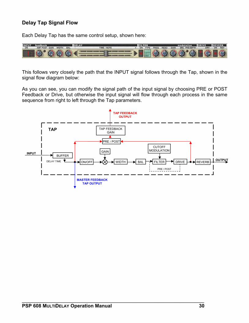
Delay Tap Signal Flow Each Delay Tap has the same control setup, shown here:
This follows very closely the path that the INPUT signal follows through the Tap, shown in the signal flow diagram below: As you can see, you can modify the signal path of the input signal by choosing PRE or POST Feedback or Drive, but otherwise the input signal will flow through each process in the same sequence from right to left through the Tap parameters.
OUTPUT
TAP FEEDBACK OUTPUT
TAP TAP FEEDBACK GAIN
PRE / POST
CUTOFF MODULATIONGAININPUT
BUFFER
DELAY TIME WIDTH BAL FILTER DRIVE ON/OFF REVERB
PRE / POST
MASTER FEEDBACK TAP OUTPUT
___________________________________________________________________ PSP 608 MULTIDELAY Operation Manual 30
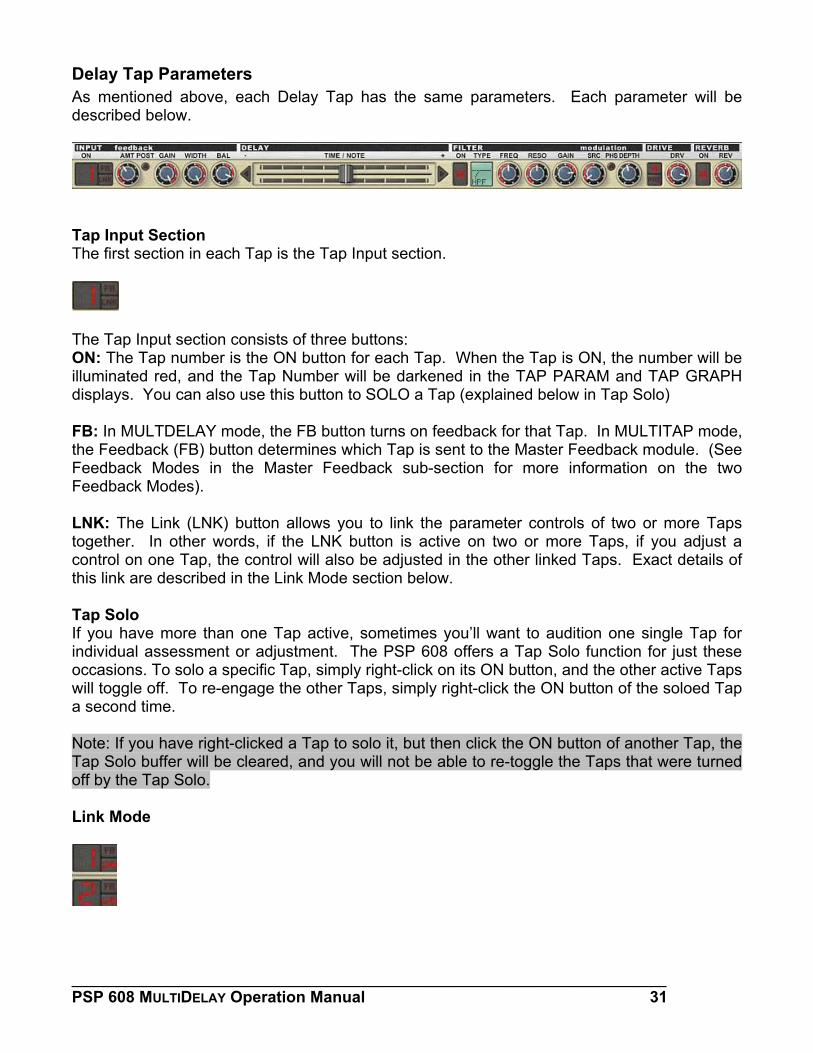
Delay Tap Parameters As mentioned above, each Delay Tap has the same parameters. Each parameter will be described below.
Tap Input Section The first section in each Tap is the Tap Input section.
The Tap Input section consists of three buttons: ON: The Tap number is the ON button for each Tap. When the Tap is ON, the number will be illuminated red, and the Tap Number will be darkened in the TAP PARAM and TAP GRAPH displays. You can also use this button to SOLO a Tap (explained below in Tap Solo) FB: In MULTDELAY mode, the FB button turns on feedback for that Tap. In MULTITAP mode, the Feedback (FB) button determines which Tap is sent to the Master Feedback module. (See Feedback Modes in the Master Feedback sub-section for more information on the two Feedback Modes). LNK: The Link (LNK) button allows you to link the parameter controls of two or more Taps together. In other words, if the LNK button is active on two or more Taps, if you adjust a control on one Tap, the control will also be adjusted in the other linked Taps. Exact details of this link are described in the Link Mode section below. Tap Solo If you have more than one Tap active, sometimes you’ll want to audition one single Tap for individual assessment or adjustment. The PSP 608 offers a Tap Solo function for just these occasions. To solo a specific Tap, simply right-click on its ON button, and the other active Taps will toggle off. To re-engage the other Taps, simply right-click the ON button of the soloed Tap a second time. Note: If you have right-clicked a Tap to solo it, but then click the ON button of another Tap, the Tap Solo buffer will be cleared, and you will not be able to re-toggle the Taps that were turned off by the Tap Solo. Link Mode
___________________________________________________________________ PSP 608 MULTIDELAY Operation Manual 31
As explained above in the Tap Input Section description, when you have the LNK button engaged on two more Taps, the controls of those Taps will be linked together; adjusting a parameter on one Tap will adjust that parameter on all linked Taps. Link Mode has a few rules and modifiers, however. DELAY Sliders in Link Mode When adjusting the DELAY slider in TIME mode, the Taps have a relative link. What this means is that the ratio of the time difference between the linked Taps is maintained. For example, lets say that one Tap has a 100ms delay, and another linked Tap has a 50ms delay. While the actual time difference between the two Taps is 50ms, the ratio is approximately 2:1. If you then shorten the first Tap to 50ms, the second Tap will be shortened to 25ms—in other words, the exact difference in time between the two taps is not maintained, the relative length of time, based on the ratio of the delays of the two Taps, is maintained. If one Tap is at 0ms, and you shorten the DELAY time of a linked Tap, or if one Tap is at 8000ms and you lengthen the DELAY time of a linked Tap, this relative link will be broken. If you are in TIME mode, and you want each linked slider to maintain their exact distance from each other, you can hold down the SHIFT key while adjusting the slider of a Tap. This will toggle the link to a proportional link. In this mode, the precise duration between the linked Taps is maintained. As with relative links, if one Tap is already at 0ms and you continue to shorten the DELAY time of a linked Tap, or if one Tap is at 8000ms and you continue to lengthen the DELAY time of a linked Tap, this proportional link will be broken. When adjusting the DELAY slider in NOTE mode, the Taps have a proportional link. This means that the proportions of the note durations between each linked Tap to another will be maintained. As above, if one Tap is already at its shortest delay and you continue to shorten the DELAY time of a linked Tap, or if one Tap is at its longest delay and you continue to lengthen the DELAY time of a linked Tap, this proportional link will be broken. If you want to adjust the DELAY slider of a Tap in Link Mode without adjusting the other linked DELAY sliders, the ALT key (OPTION on the Macintosh) can act as a sort of “clutch” or “quick toggle.” Just hold the ALT/OPTION key down while moving the DELAY slider of a linked Tap, and only that Tap will be affected. Parameter Knobs in Link Mode The parameter knobs are also linked when more than one Tap is in Link mode. Parameter knobs always have a proportional link with the parameter knobs of other Taps (see above for the explanation of proportional linking). Like the DELAY slider, if you hold ALT/OPTION down when adjusting a parameter knob, only that knob will be adjusted. If you hold the SHIFT key down while adjusting a parameter knob, the corresponding parameter in other linked Taps will jump to the same value as the adjusted parameter.
___________________________________________________________________ PSP 608 MULTIDELAY Operation Manual 32
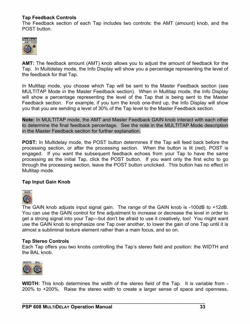
Tap Feedback Controls The Feedback section of each Tap includes two controls: the AMT (amount) knob, and the POST button.
AMT: The feedback amount (AMT) knob allows you to adjust the amount of feedback for the Tap. In Multidelay mode, the Info Display will show you a percentage representing the level of the feedback for that Tap. In Multitap mode, you choose which Tap will be sent to the Master Feedback section (see MULTITAP Mode in the Master Feedback section). When in Multitap mode, the Info Display will show a percentage representing the level of the Tap that is being sent to the Master Feedback section. For example, if you turn the knob one-third up, the Info Display will show you that you are sending a level of 30% of the Tap level to the Master Feedback section. Note: In MULTITAP mode, the AMT and Master Feedback GAIN knob interact with each other to determine the final feedback percentage. See the note in the MULTITAP Mode description in the Master Feedback section for further explanation. POST: In Multidelay mode, the POST button determines if the Tap will feed back before the processing section, or after the processing section. When the button is lit (red), POST is engaged. If you want the subsequent feedback echoes from your Tap to have the same processing as the initial Tap, click the POST button. If you want only the first echo to go through the processing section, leave the POST button unclicked. This button has no effect in Multitap mode. Tap Input Gain Knob
The GAIN knob adjusts input signal gain. The range of the GAIN knob is -100dB to +12dB. You can use the GAIN control for fine adjustment to increase or decrease the level in order to get a strong signal into your Tap—but don’t be afraid to use it creatively, too! You might want use the GAIN knob to emphasize one Tap over another, to lower the gain of one Tap until it is almost a subliminal texture element rather than a main focus, and so on. Tap Stereo Controls Each Tap offers you two knobs controlling the Tap’s stereo field and position: the WIDTH and the BAL knob.
WIDTH: This knob determines the width of the stereo field of the Tap. It is variable from -200% to +200%. Raise the stereo width to create a larger sense of space and openness,
___________________________________________________________________ PSP 608 MULTIDELAY Operation Manual 33
reduce the stereo width to create a smaller and narrower space. When you are using multiple Taps, you can utilize this to give different Taps different stereo fields, making each Tap even more distinct. By holding down the CONTROL/COMMAND key and clicking, you can access the three default positions of these knobs. BAL: This knob adjusts the balance, or emphasis between the right stereo image and left stereo image. This has the effect of changing the perceived location of the Tap in the stereo field. Keep in mind that if you are instantiating this plug-in on a MONO audio track, the BAL knob will only have the effect of strengthening or weakening the signal, depending on how far you have adjusted the balance from the center position. The DELAY Slider
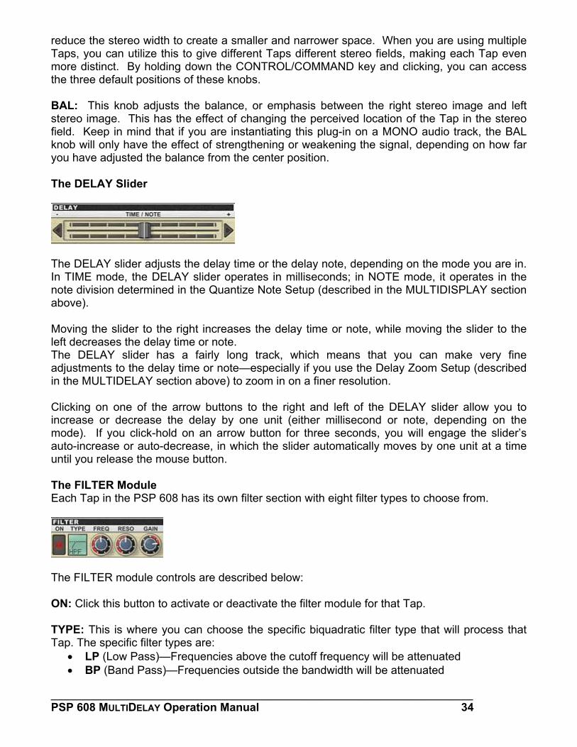
The DELAY slider adjusts the delay time or the delay note, depending on the mode you are in. In TIME mode, the DELAY slider operates in milliseconds; in NOTE mode, it operates in the note division determined in the Quantize Note Setup (described in the MULTIDISPLAY section above). Moving the slider to the right increases the delay time or note, while moving the slider to the left decreases the delay time or note. The DELAY slider has a fairly long track, which means that you can make very fine adjustments to the delay time or note—especially if you use the Delay Zoom Setup (described in the MULTIDELAY section above) to zoom in on a finer resolution. Clicking on one of the arrow buttons to the right and left of the DELAY slider allow you to increase or decrease the delay by one unit (either millisecond or note, depending on the mode). If you click-hold on an arrow button for three seconds, you will engage the slider’s auto-increase or auto-decrease, in which the slider automatically moves by one unit at a time until you release the mouse button. The FILTER Module Each Tap in the PSP 608 has its own filter section with eight filter types to choose from.
The FILTER module controls are described below: ON: Click this button to activate or deactivate the filter module for that Tap. TYPE: This is where you can choose the specific biquadratic filter type that will process that Tap. The specific filter types are:
• LP (Low Pass)—Frequencies above the cutoff frequency will be attenuated • BP (Band Pass)—Frequencies outside the bandwidth will be attenuated
___________________________________________________________________ PSP 608 MULTIDELAY Operation Manual 34
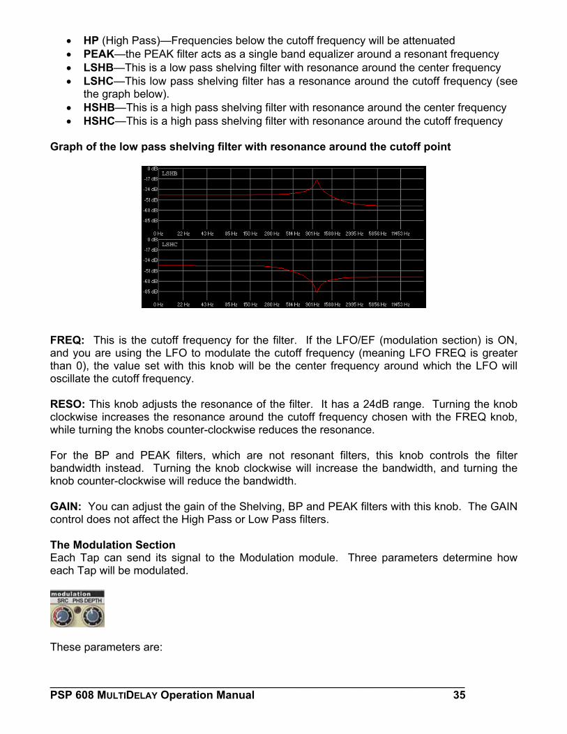
• HP (High Pass)—Frequencies below the cutoff frequency will be attenuated • PEAK—the PEAK filter acts as a single band equalizer around a resonant frequency • LSHB—This is a low pass shelving filter with resonance around the center frequency • LSHC—This low pass shelving filter has a resonance around the cutoff frequency (see
the graph below). • HSHB—This is a high pass shelving filter with resonance around the center frequency • HSHC—This is a high pass shelving filter with resonance around the cutoff frequency
Graph of the low pass shelving filter with resonance around the cutoff point
FREQ: This is the cutoff frequency for the filter. If the LFO/EF (modulation section) is ON, and you are using the LFO to modulate the cutoff frequency (meaning LFO FREQ is greater than 0), the value set with this knob will be the center frequency around which the LFO will oscillate the cutoff frequency. RESO: This knob adjusts the resonance of the filter. It has a 24dB range. Turning the knob clockwise increases the resonance around the cutoff frequency chosen with the FREQ knob, while turning the knobs counter-clockwise reduces the resonance. For the BP and PEAK filters, which are not resonant filters, this knob controls the filter bandwidth instead. Turning the knob clockwise will increase the bandwidth, and turning the knob counter-clockwise will reduce the bandwidth. GAIN: You can adjust the gain of the Shelving, BP and PEAK filters with this knob. The GAIN control does not affect the High Pass or Low Pass filters. The Modulation Section Each Tap can send its signal to the Modulation module. Three parameters determine how each Tap will be modulated.
These parameters are:
___________________________________________________________________ PSP 608 MULTIDELAY Operation Manual 35
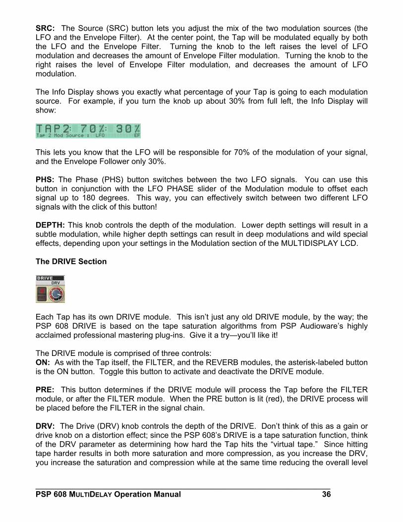
SRC: The Source (SRC) button lets you adjust the mix of the two modulation sources (the LFO and the Envelope Filter). At the center point, the Tap will be modulated equally by both the LFO and the Envelope Filter. Turning the knob to the left raises the level of LFO modulation and decreases the amount of Envelope Filter modulation. Turning the knob to the right raises the level of Envelope Filter modulation, and decreases the amount of LFO modulation. The Info Display shows you exactly what percentage of your Tap is going to each modulation source. For example, if you turn the knob up about 30% from full left, the Info Display will show:
This lets you know that the LFO will be responsible for 70% of the modulation of your signal, and the Envelope Follower only 30%. PHS: The Phase (PHS) button switches between the two LFO signals. You can use this button in conjunction with the LFO PHASE slider of the Modulation module to offset each signal up to 180 degrees. This way, you can effectively switch between two different LFO signals with the click of this button! DEPTH: This knob controls the depth of the modulation. Lower depth settings will result in a subtle modulation, while higher depth settings can result in deep modulations and wild special effects, depending upon your settings in the Modulation section of the MULTIDISPLAY LCD. The DRIVE Section
Each Tap has its own DRIVE module. This isn’t just any old DRIVE module, by the way; the PSP 608 DRIVE is based on the tape saturation algorithms from PSP Audioware’s highly acclaimed professional mastering plug-ins. Give it a try—you’ll like it! The DRIVE module is comprised of three controls: ON: As with the Tap itself, the FILTER, and the REVERB modules, the asterisk-labeled button is the ON button. Toggle this button to activate and deactivate the DRIVE module. PRE: This button determines if the DRIVE module will process the Tap before the FILTER module, or after the FILTER module. When the PRE button is lit (red), the DRIVE process will be placed before the FILTER in the signal chain. DRV: The Drive (DRV) knob controls the depth of the DRIVE. Don’t think of this as a gain or drive knob on a distortion effect; since the PSP 608’s DRIVE is a tape saturation function, think of the DRV parameter as determining how hard the Tap hits the “virtual tape.” Since hitting tape harder results in both more saturation and more compression, as you increase the DRV, you increase the saturation and compression while at the same time reducing the overall level
___________________________________________________________________ PSP 608 MULTIDELAY Operation Manual 36
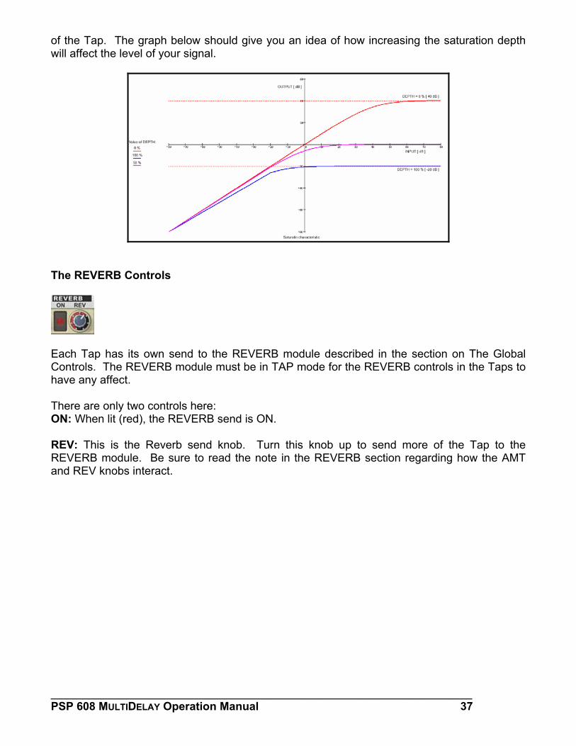
of the Tap. The graph below should give you an idea of how increasing the saturation depth will affect the level of your signal.
The REVERB Controls
Each Tap has its own send to the REVERB module described in the section on The Global Controls. The REVERB module must be in TAP mode for the REVERB controls in the Taps to have any affect. There are only two controls here: ON: When lit (red), the REVERB send is ON. REV: This is the Reverb send knob. Turn this knob up to send more of the Tap to the REVERB module. Be sure to read the note in the REVERB section regarding how the AMT and REV knobs interact.
___________________________________________________________________ PSP 608 MULTIDELAY Operation Manual 37
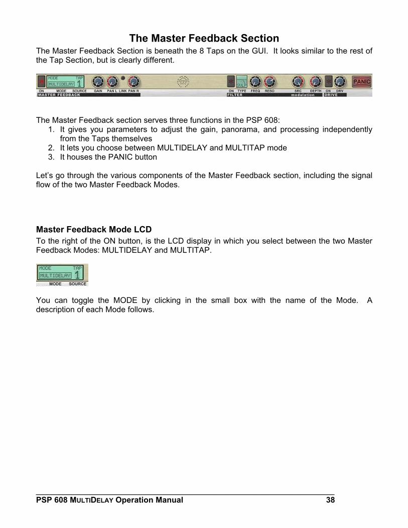
The Master Feedback Section The Master Feedback Section is beneath the 8 Taps on the GUI. It looks similar to the rest of the Tap Section, but is clearly different.
The Master Feedback section serves three functions in the PSP 608:
1. It gives you parameters to adjust the gain, panorama, and processing independently from the Taps themselves
2. It lets you choose between MULTIDELAY and MULTITAP mode 3. It houses the PANIC button
Let’s go through the various components of the Master Feedback section, including the signal flow of the two Master Feedback Modes.
Master Feedback Mode LCD To the right of the ON button, is the LCD display in which you select between the two Master Feedback Modes: MULTIDELAY and MULTITAP.
You can toggle the MODE by clicking in the small box with the name of the Mode. A description of each Mode follows.
___________________________________________________________________ PSP 608 MULTIDELAY Operation Manual 38
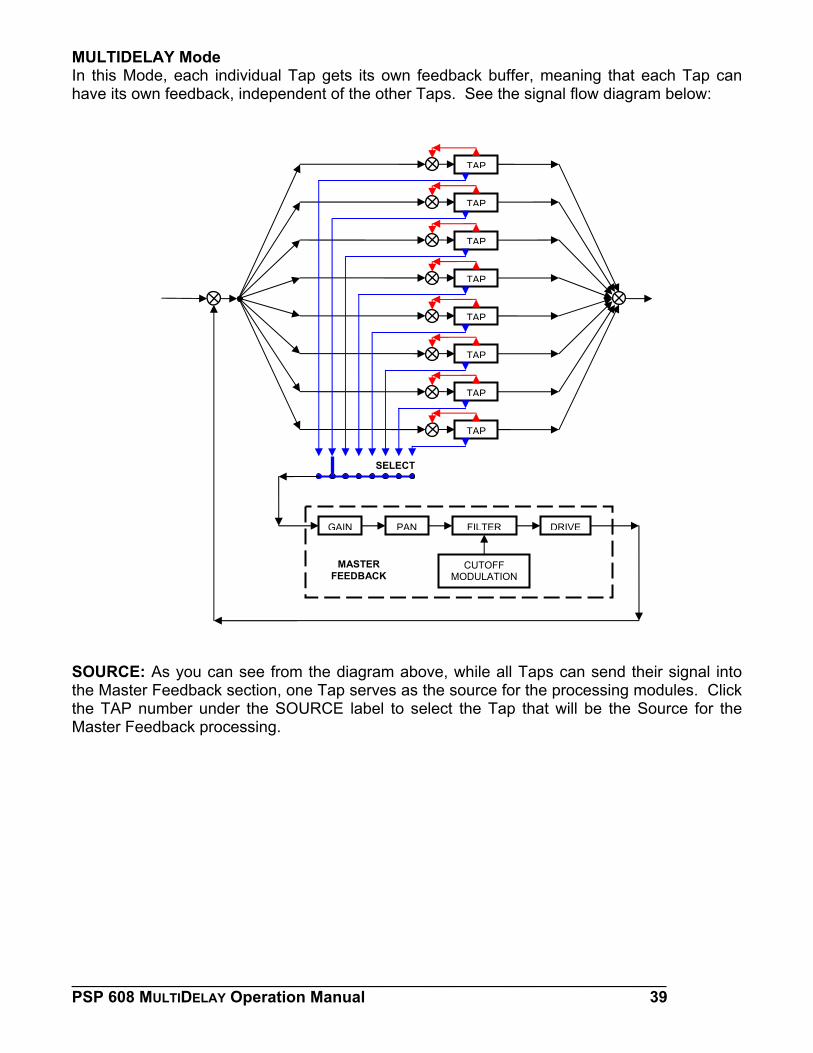
MULTIDELAY Mode In this Mode, each individual Tap gets its own feedback buffer, meaning that each Tap can have its own feedback, independent of the other Taps. See the signal flow diagram below:
TAP
TAP
TAP
TAP
TAP
TAP
TAP
TAP
SELECT
GAIN PAN FILTER DRIVE
MASTER FEEDBACK
CUTOFF MODULATION
SOURCE: As you can see from the diagram above, while all Taps can send their signal into the Master Feedback section, one Tap serves as the source for the processing modules. Click the TAP number under the SOURCE label to select the Tap that will be the Source for the Master Feedback processing.
___________________________________________________________________ PSP 608 MULTIDELAY Operation Manual 39
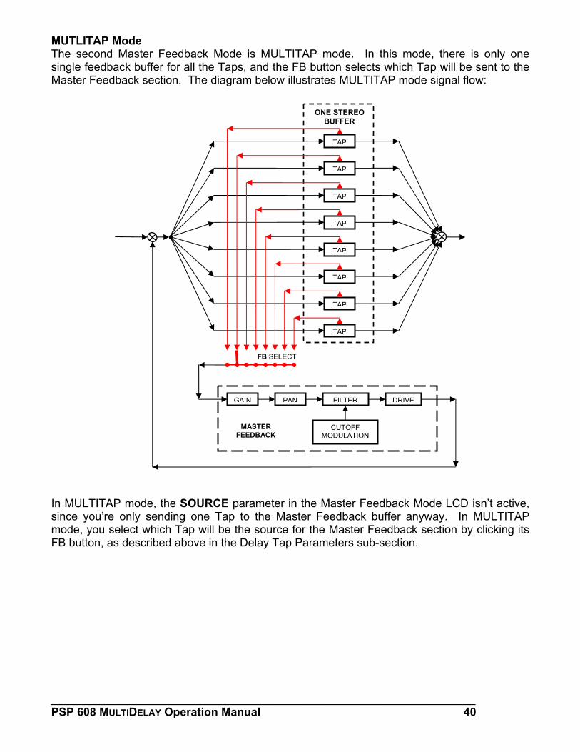
MUTLITAP Mode The second Master Feedback Mode is MULTITAP mode. In this mode, there is only one single feedback buffer for all the Taps, and the FB button selects which Tap will be sent to the Master Feedback section. The diagram below illustrates MULTITAP mode signal flow:
ONE STEREO BUFFER
TAP
TAP
TAP
TAP
TAP
TAP
TAP
TAP
FB SELECT
GAIN PAN FILTER DRIVE
MASTER FEEDBACK
CUTOFF MODULATION
In MULTITAP mode, the SOURCE parameter in the Master Feedback Mode LCD isn’t active, since you’re only sending one Tap to the Master Feedback buffer anyway. In MULTITAP mode, you select which Tap will be the source for the Master Feedback section by clicking its FB button, as described above in the Delay Tap Parameters sub-section.
___________________________________________________________________ PSP 608 MULTIDELAY Operation Manual 40
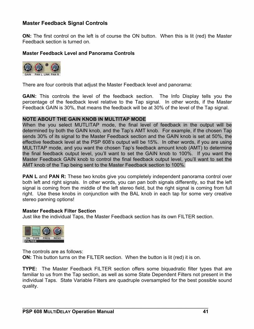
Master Feedback Signal Controls ON: The first control on the left is of course the ON button. When this is lit (red) the Master Feedback section is turned on. Master Feedback Level and Panorama Controls
There are four controls that adjust the Master Feedback level and panorama: GAIN: This controls the level of the feedback section. The Info Display tells you the percentage of the feedback level relative to the Tap signal. In other words, if the Master Feedback GAIN is 30%, that means the feedback will be at 30% of the level of the Tap signal. NOTE ABOUT THE GAIN KNOB IN MULTITAP MODE When the you select MUTLITAP mode, the final level of feedback in the output will be determined by both the GAIN knob, and the Tap’s AMT knob. For example, if the chosen Tap sends 30% of its signal to the Master Feedback section and the GAIN knob is set at 50%, the effective feedback level at the PSP 608’s output will be 15%. In other words, if you are using MULTITAP mode, and you want the chosen Tap’s feedback amount knob (AMT) to determine the final feedback output level, you’ll want to set the GAIN knob to 100%. If you want the Master Feedback GAIN knob to control the final feedback output level, you’ll want to set the AMT knob of the Tap being sent to the Master Feedback section to 100%. PAN L and PAN R: These two knobs give you completely independent panorama control over both left and right signals. In other words, you can pan both signals differently, so that the left signal is coming from the middle of the left stereo field, but the right signal is coming from full right. Use these knobs in conjunction with the BAL knob in each tap for some very creative stereo panning options! Master Feedback Filter Section Just like the individual Taps, the Master Feedback section has its own FILTER section.
The controls are as follows: ON: This button turns on the FILTER section. When the button is lit (red) it is on. TYPE: The Master Feedback FILTER section offers some biquadratic filter types that are familiar to us from the Tap section, as well as some State Dependent Filters not present in the individual Taps. State Variable Filters are quadruple oversampled for the best possible sound quality.
___________________________________________________________________ PSP 608 MULTIDELAY Operation Manual 41
The available Master Feedback module filter types are: • BQHP (Biquadratic High Pass)—This filter is the same as the Tap Section’s HP filter • SVHP (State Variable High Pass)—This is a high pass filter that adds a slight saturation • BQLP (Biquadratic Low Pass)—This filter is the same as the Tap Section’s LP filter • SVLP (State Variable Low Pass)—this is a low pass filter that adds a slight saturation • BQBP (Biquadratic Band Pass)—This filter is the same as the Tap Section’s BP filter • SVBP (State Variable Band Pass)—This is a band pass filter that adds a slight
saturation FREQ: This is the cutoff frequency for the filter. If the LFO/EF (modulation section) is ON, and you are using the LFO to modulate the cutoff frequency (meaning LFO FREQ is greater than 0), the value set with this knob will be the center frequency around which the LFO will oscillate the cutoff frequency. RESO: This knob adjusts the resonance of the filter. It has a 12dB range. Turning the knob clockwise increases the resonance around the cutoff frequency chosen with the FREQ knob, while turning the knobs counter-clockwise reduces the resonance. For the BP filters, which are not resonant filters, this knob controls the filter bandwidth instead. Turning the knob clockwise will increase the bandwidth, and turning the knob counter-clockwise will reduce the bandwidth. WARNING! When you turn on the filter in both an individual Tap and the Master Feedback section, the sharp resonances created and you can very easily overload your sound! The PSP 608 has some built in protections against overloading your speakers—any signal 24dB over the original signal will be reduced to exactly 24dB over the original signal (this overload protection affects both the Tap and Master Feedback output). Always start with low feedback and resonance values when using multiple filters and increase them gradually until you achieve the desired effect. When experimenting, it’s a good idea to lower the plug-in master output level as well. Master Feedback Modulation Section
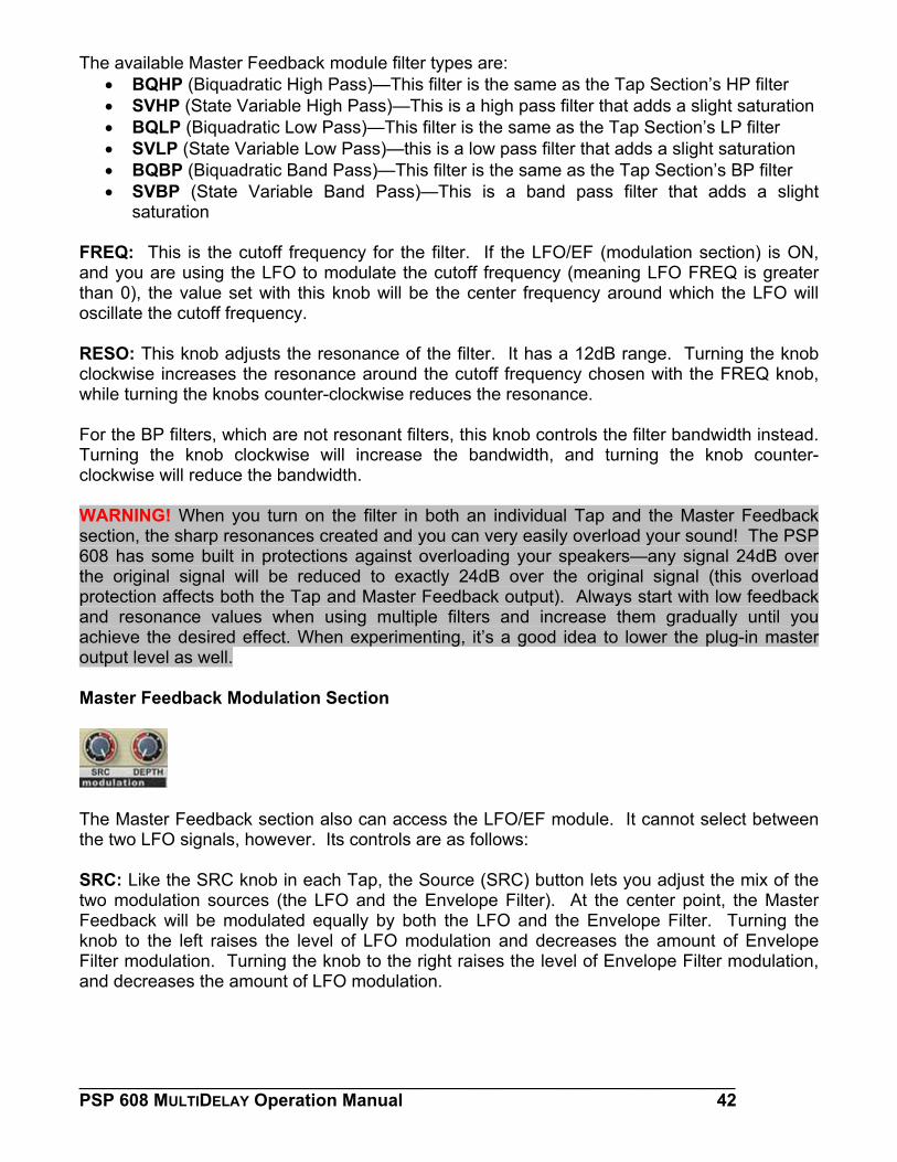
The Master Feedback section also can access the LFO/EF module. It cannot select between the two LFO signals, however. Its controls are as follows: SRC: Like the SRC knob in each Tap, the Source (SRC) button lets you adjust the mix of the two modulation sources (the LFO and the Envelope Filter). At the center point, the Master Feedback will be modulated equally by both the LFO and the Envelope Filter. Turning the knob to the left raises the level of LFO modulation and decreases the amount of Envelope Filter modulation. Turning the knob to the right raises the level of Envelope Filter modulation, and decreases the amount of LFO modulation.
___________________________________________________________________ PSP 608 MULTIDELAY Operation Manual 42
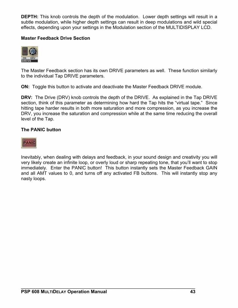
DEPTH: This knob controls the depth of the modulation. Lower depth settings will result in a subtle modulation, while higher depth settings can result in deep modulations and wild special effects, depending upon your settings in the Modulation section of the MULTIDISPLAY LCD. Master Feedback Drive Section
The Master Feedback section has its own DRIVE parameters as well. These function similarly to the individual Tap DRIVE parameters. ON: Toggle this button to activate and deactivate the Master Feedback DRIVE module. DRV: The Drive (DRV) knob controls the depth of the DRIVE. As explained in the Tap DRIVE section, think of this parameter as determining how hard the Tap hits the “virtual tape.” Since hitting tape harder results in both more saturation and more compression, as you increase the DRV, you increase the saturation and compression while at the same time reducing the overall level of the Tap. The PANIC button
Inevitably, when dealing with delays and feedback, in your sound design and creativity you will very likely create an infinite loop, or overly loud or sharp repeating tone, that you’ll want to stop immediately. Enter the PANIC button! This button instantly sets the Master Feedback GAIN and all AMT values to 0, and turns off any activated FB buttons. This will instantly stop any nasty loops.
___________________________________________________________________ PSP 608 MULTIDELAY Operation Manual 43
The Preset Bar As with nearly all modern software processors, the PSP 608 allows you to save the current state of each parameter as a Preset. With the PSP 608, you can also save groups of presets called Banks; this allows you even more organizational flexibility. You might, for example, create one Bank that holds all of your presets, another Bank to include only those few you want to use for a given project, and still another Bank of presets you like you use live. The PSP 608 offers all of its preset management functions on a convenient Preset Bar at the bottom of the plug-in interface, right below the Master Feedback section. Here you will find all the controls to load, save, and select individual presets or banks of presets.
The majority of the Preset Bar contains the controls for saving, loading, and selecting individual presets. The right side of the bar allows you to save and load Banks of presets. Below is a brief description of each control on the Preset Bar.
Load Preset Button When you click the green floppy disk icon next to the word PRESET, you will be presented with a file dialog box asking you to select a preset to load. This preset will then be loaded into as the active preset. The previously loaded preset will still be present in the Preset Menu (see below).
Save Preset Button When you click the red floppy disk icon to the right of the LOAD PRESET icon, you will be presented with the Save Preset dialog box. After selecting a name and a location to save your preset, your PSP 608 preset will be saved to disk.
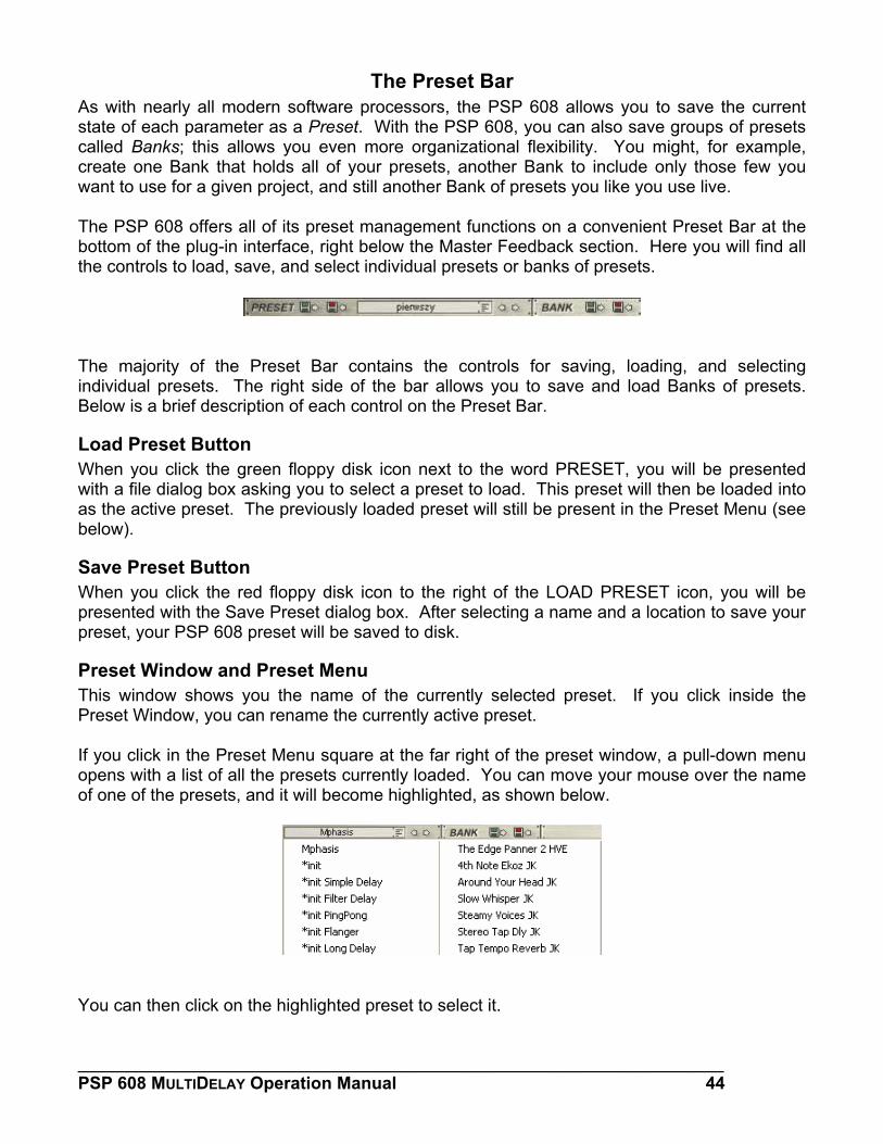
Preset Window and Preset Menu This window shows you the name of the currently selected preset. If you click inside the Preset Window, you can rename the currently active preset. If you click in the Preset Menu square at the far right of the preset window, a pull-down menu opens with a list of all the presets currently loaded. You can move your mouse over the name of one of the presets, and it will become highlighted, as shown below.
You can then click on the highlighted preset to select it.
___________________________________________________________________ PSP 608 MULTIDELAY Operation Manual 44
Preset Selection Arrows You can also use the two arrows to the right of the Preset Window to select a preset from the current Preset Bank. Clicking the left arrow scrolls backwards from the currently selected preset through the Preset Menu. Clicking the right arrow scrolls forwards from the currently selected preset through the preset menu.
Load Bank Button Clicking on the first button in the Bank section of the Preset Bar brings up the Load Bank dialog box. This looks just like the Load Preset dialog box, with the exception that instead of only the active preset being replaced, every preset currently loaded into the Preset Menu will be replaced with the presets from the loaded Bank.
Save Bank Button The button to the right of the Load Bank Button is the Save Bank Button. Clicking on this button will bring up the Save Bank dialog window. This window is similar to the Save Preset dialog, except that instead of only the active preset being saved, every preset currently loaded into the Preset Menu will be saved as a Bank.
___________________________________________________________________ PSP 608 MULTIDELAY Operation Manual 45
Support If you have any questions about the principles or operation of our plug-ins, please visit our website www.PSPaudioware.com where you can find the latest product information, free software updates and answers to the most frequently asked questions. You can also contact us by e-mail: [email protected] We will gladly answer all of your questions. As a rule we respond within 24 hours. PSPaudioware.com s.c. Dzikiej Rozy 11/8 Jozefoslaw 05-509 Piaseczno Poland ph. +48 601 96 31 73 www.PSPaudioware.com [email protected]
___________________________________________________________________ PSP 608 MULTIDELAY Operation Manual 46
___________________________________________________________________ PSP 608 MULTIDELAY Operation Manual 47
User Comments We welcome any opinions and comments related to PSP 608. We would also be grateful if you shared with us your experiences using PSP 608. For example, if you’ve created a useful preset then let us know. Please, contact us at: [email protected]