pSOSystem System Concepts - Freebagfed.free.fr/pSOS/PSOS_System_Concepts.pdf · pSOSystem Product...
334
pSOSystem Product Family pSOSystem System Concepts 000-5433-001
Transcript of pSOSystem System Concepts - Freebagfed.free.fr/pSOS/PSOS_System_Concepts.pdf · pSOSystem Product...

pSOSystem Product Family
pSOSystemSystem Concepts
000-5433-001
sc.book Page i Friday, January 8, 1999 2:07 PM

Integrated Systems, Inc. • 201 Moffett Park Drive • Sunnyvale, CA 94089-1322
LICENSED SOFTWARE - CONFIDENTIAL/PROPRIETARYThis document and the associated software contain information proprietary to IntegratedSystems, Inc., or its licensors and may be used only in accordance with the IntegratedSystems license agreement under which this package is provided. No part of thisdocument may be copied, reproduced, transmitted, translated, or reduced to anyelectronic medium or machine-readable form without the prior written consent ofIntegrated Systems.
Integrated Systems makes no representation with respect to the contents, and assumesno responsibility for any errors that might appear in this document. Integrated Systemsspecifically disclaims any implied warranties of merchantability or fitness for a particularpurpose. This publication and the contents hereof are subject to change without notice.
RESTRICTED RIGHTS LEGENDUse, duplication, or disclosure by the Government is subject to restrictions as set forth insubparagraph (c)(1)(ii) of the Rights in Technical Data and Computer Software clause atDFARS252.227-7013 or its equivalent. Unpublished rights reserved under the copyrightlaws of the United States.
TRADEMARKSAutoCode, ESp, MATRIXX, pRISM, pRISM+, pSOS, SpOTLIGHT, and Xmath are registeredtrademarks of Integrated Systems, Inc. BetterState, BetterState Lite, BetterState Pro,DocumentIt, Epilogue, HyperBuild, OpEN, OpTIC, pHILE+, pLUG&SIM, pNA+, pREPC+,pROBE+, pRPC+, pSET, pSOS+, pSOS+m, pSOSim, pSOSystem, pX11+, RealSim,SystemBuild, and ZeroCopy are trademarks of Integrated Systems, Inc.
ARM is a trademark of Advanced RISC Machines Limited. Diab Data and Diab Data incombination with D-AS, D-C++, D-CC, D-F77, and D-LD are trademarks of Diab Data, Inc.ELANIX, Signal Analysis Module, and SAM are trademarks of ELANIX, Inc. SingleStep is atrademark of Software Development Systems, Inc. SNiFF+ is a trademark of TakeFiveSoftware GmbH, Austria, a wholly-owned subsidiary of Integrated Systems, Inc.
All other products mentioned are the trademarks, service marks, or registered trademarksof their respective holders.
Copyright 1999 Integrated Systems, Inc. All rights reserved. Printed in U.S.A.Document Title: pSOSystem System ConceptsPart Number: 000-5433-001Revision Date: January 1999
Corporate pSOS or pRISM+ Support MATRIX X Support
Phone 408-542-1500 1-800-458-7767, 408-542-1925 1-800-958-8885, 408-542-1930
Fax 408-542-1950 408-542-1966 408-542-1951
E-mail [email protected] [email protected] [email protected]
Home Page http://www.isi.com
sc.book Page ii Friday, January 8, 1999 2:07 PM

sc.book Page iii Friday, January 8, 1999 2:07 PM
Contents
Using This Manual xv
Purpose . . . . . . . . . . . . . . . . . . . . . . . . . . . . . . . . . . . . . . . . . . . . . . . . . . . . . . . .xv
Audience . . . . . . . . . . . . . . . . . . . . . . . . . . . . . . . . . . . . . . . . . . . . . . . . . . . . . . .xv
Organization . . . . . . . . . . . . . . . . . . . . . . . . . . . . . . . . . . . . . . . . . . . . . . . . . . . xvi
Related Documentation . . . . . . . . . . . . . . . . . . . . . . . . . . . . . . . . . . . . . . . . . . . xvi
Notation Conventions. . . . . . . . . . . . . . . . . . . . . . . . . . . . . . . . . . . . . . . . . . . . . xix
Support . . . . . . . . . . . . . . . . . . . . . . . . . . . . . . . . . . . . . . . . . . . . . . . . . . . . . . . .xx
1 Product Overview
1.1 What Is pSOSystem? . . . . . . . . . . . . . . . . . . . . . . . . . . . . . . . . . . . . . . . 1-1
1.2 System Architecture . . . . . . . . . . . . . . . . . . . . . . . . . . . . . . . . . . . . . . . 1-1
1.3 Integrated Development Environment . . . . . . . . . . . . . . . . . . . . . . . . . . 1-4
2 pSOS+ Real-Time Kernel
2.1 Overview . . . . . . . . . . . . . . . . . . . . . . . . . . . . . . . . . . . . . . . . . . . . . . . . 2-1
2.1.1 Multitasking Implementation . . . . . . . . . . . . . . . . . . . . . . . . . . . . 2-2
2.1.2 Objects, Names, and IDs . . . . . . . . . . . . . . . . . . . . . . . . . . . . . . . 2-4
2.1.3 Overview of System Operations. . . . . . . . . . . . . . . . . . . . . . . . . . . 2-5
iii

Contents pSOSystem System Concepts
sc.book Page iv Friday, January 8, 1999 2:07 PM
2.2 Task Management. . . . . . . . . . . . . . . . . . . . . . . . . . . . . . . . . . . . . . . . . 2-6
2.2.1 Concept of a Task . . . . . . . . . . . . . . . . . . . . . . . . . . . . . . . . . . . . 2-7
2.2.2 Task States . . . . . . . . . . . . . . . . . . . . . . . . . . . . . . . . . . . . . . . . . 2-7
2.2.3 State Transitions . . . . . . . . . . . . . . . . . . . . . . . . . . . . . . . . . . . . . 2-8
2.2.4 Task Scheduling . . . . . . . . . . . . . . . . . . . . . . . . . . . . . . . . . . . . 2-11
2.2.5 Task Priorities - Assigning and Changing . . . . . . . . . . . . . . . . . . 2-11
2.2.6 Roundrobin by Timeslicing . . . . . . . . . . . . . . . . . . . . . . . . . . . . 2-13
2.2.7 Manual Roundrobin. . . . . . . . . . . . . . . . . . . . . . . . . . . . . . . . . . 2-15
2.2.8 Dispatch Criteria . . . . . . . . . . . . . . . . . . . . . . . . . . . . . . . . . . . . 2-15
2.2.9 Creation of a Task . . . . . . . . . . . . . . . . . . . . . . . . . . . . . . . . . . . 2-16
2.2.10 Task Control Block . . . . . . . . . . . . . . . . . . . . . . . . . . . . . . . . . . 2-17
2.2.11 Task Mode Word . . . . . . . . . . . . . . . . . . . . . . . . . . . . . . . . . . . . 2-18
2.2.12 Per-task Timeslice Quantum . . . . . . . . . . . . . . . . . . . . . . . . . . . 2-18
2.2.13 Task Stacks. . . . . . . . . . . . . . . . . . . . . . . . . . . . . . . . . . . . . . . . 2-19
2.2.14 Task Memory. . . . . . . . . . . . . . . . . . . . . . . . . . . . . . . . . . . . . . . 2-19
2.2.15 Death of a Task . . . . . . . . . . . . . . . . . . . . . . . . . . . . . . . . . . . . . 2-19
2.2.16 Notepad Registers/Task Variables/Task-specificData Management . . . . . . . . . . . . . . . . . . . . . . . . . . . . . . . . . . . 2-20
2.2.17 Querying a Task Object . . . . . . . . . . . . . . . . . . . . . . . . . . . . . . . 2-20
2.2.18 The Idle Task. . . . . . . . . . . . . . . . . . . . . . . . . . . . . . . . . . . . . . . 2-20
2.3 Storage Allocation . . . . . . . . . . . . . . . . . . . . . . . . . . . . . . . . . . . . . . . . 2-21
2.3.1 Regions and Segments. . . . . . . . . . . . . . . . . . . . . . . . . . . . . . . . 2-21
2.3.2 Special Region 0 . . . . . . . . . . . . . . . . . . . . . . . . . . . . . . . . . . . . 2-22
2.3.3 Allocation Algorithm . . . . . . . . . . . . . . . . . . . . . . . . . . . . . . . . . 2-23
2.3.4 Partitions and Buffers . . . . . . . . . . . . . . . . . . . . . . . . . . . . . . . . 2-23
2.4 Communication, Synchronization, Mutual Exclusion . . . . . . . . . . . . . 2-24
iv

pSOSystem System Concepts Contents
sc.book Page v Friday, January 8, 1999 2:07 PM
2.5 The Message Queue. . . . . . . . . . . . . . . . . . . . . . . . . . . . . . . . . . . . . . . 2-25
2.5.1 The Queue Control Block . . . . . . . . . . . . . . . . . . . . . . . . . . . . . . 2-26
2.5.2 Queue Operations . . . . . . . . . . . . . . . . . . . . . . . . . . . . . . . . . . . 2-26
2.5.3 Messages and Message Buffers. . . . . . . . . . . . . . . . . . . . . . . . . . 2-27
2.5.4 Two Examples of Queue Usage . . . . . . . . . . . . . . . . . . . . . . . . . . 2-28
2.5.5 Variable Length Message Queues . . . . . . . . . . . . . . . . . . . . . . . . 2-29
2.6 Events . . . . . . . . . . . . . . . . . . . . . . . . . . . . . . . . . . . . . . . . . . . . . . . . . 2-31
2.6.1 Event Operations . . . . . . . . . . . . . . . . . . . . . . . . . . . . . . . . . . . . 2-31
2.6.2 Events Versus Messages. . . . . . . . . . . . . . . . . . . . . . . . . . . . . . . 2-32
2.7 Semaphores. . . . . . . . . . . . . . . . . . . . . . . . . . . . . . . . . . . . . . . . . . . . . 2-32
2.7.1 The Semaphore Control Block . . . . . . . . . . . . . . . . . . . . . . . . . . 2-33
2.7.2 Semaphore Operations . . . . . . . . . . . . . . . . . . . . . . . . . . . . . . . . 2-33
2.8 Mutexes. . . . . . . . . . . . . . . . . . . . . . . . . . . . . . . . . . . . . . . . . . . . . . . . 2-34
2.8.1 The Mutex Control Block . . . . . . . . . . . . . . . . . . . . . . . . . . . . . . 2-35
2.8.2 Mutex Operations. . . . . . . . . . . . . . . . . . . . . . . . . . . . . . . . . . . . 2-36
2.8.3 The Problem of Unbounded Priority Inversion . . . . . . . . . . . . . . . 2-36
2.8.4 Priority Inheritance . . . . . . . . . . . . . . . . . . . . . . . . . . . . . . . . . . 2-37
2.8.5 Priority Protect or Priority Ceiling . . . . . . . . . . . . . . . . . . . . . . . . 2-38
2.8.6 Comparison of Priority Inheritance and PriorityCeiling Protocols. . . . . . . . . . . . . . . . . . . . . . . . . . . . . . . . . . . . . 2-38
2.8.7 Transitive Blocking of Tasks . . . . . . . . . . . . . . . . . . . . . . . . . . . . 2-39
2.8.8 Mutual Deadlocks . . . . . . . . . . . . . . . . . . . . . . . . . . . . . . . . . . . 2-40
2.9 Condition Variables . . . . . . . . . . . . . . . . . . . . . . . . . . . . . . . . . . . . . . . 2-41
2.9.1 The Condition Variable Control Block. . . . . . . . . . . . . . . . . . . . . 2-42
2.9.2 Condition Variable Operations . . . . . . . . . . . . . . . . . . . . . . . . . . 2-42
2.10 Asynchronous Signals . . . . . . . . . . . . . . . . . . . . . . . . . . . . . . . . . . . . . 2-43
2.10.1 The ASR. . . . . . . . . . . . . . . . . . . . . . . . . . . . . . . . . . . . . . . . . . . 2-44
2.10.2 Asynchronous Signal Operations . . . . . . . . . . . . . . . . . . . . . . . . 2-44
v

Contents pSOSystem System Concepts
sc.book Page vi Friday, January 8, 1999 2:07 PM
2.10.3 Signals Versus Events . . . . . . . . . . . . . . . . . . . . . . . . . . . . . . . . 2-44
2.11 Notepad Registers . . . . . . . . . . . . . . . . . . . . . . . . . . . . . . . . . . . . . . . . 2-45
2.12 Task Variables . . . . . . . . . . . . . . . . . . . . . . . . . . . . . . . . . . . . . . . . . . 2-45
2.13 Task-Specific Data Management . . . . . . . . . . . . . . . . . . . . . . . . . . . . . 2-47
2.13.1 The Mechanism for Task-Specific Data Support (TSD Arrays andTSD Anchor) . . . . . . . . . . . . . . . . . . . . . . . . . . . . . . . . . . . . . . . 2-47
2.13.2 Creation of a TSD Object . . . . . . . . . . . . . . . . . . . . . . . . . . . . . . 2-49
2.13.3 Task-Specific Data Control Block. . . . . . . . . . . . . . . . . . . . . . . . 2-51
2.13.4 Task-Specific Data Operations . . . . . . . . . . . . . . . . . . . . . . . . . . 2-51
2.13.5 Task-specific Data and the pSOS+ System Startup Callout . . . . 2-52
2.13.6 Task-Specific Data Object Deletion . . . . . . . . . . . . . . . . . . . . . . 2-53
2.14 Task Startup, Restart and Deletion Callouts . . . . . . . . . . . . . . . . . . . . 2-53
2.14.1 Callout Registration. . . . . . . . . . . . . . . . . . . . . . . . . . . . . . . . . . 2-53
2.14.2 Callout Execution Restrictions. . . . . . . . . . . . . . . . . . . . . . . . . . 2-54
2.14.3 Unregistering Callouts . . . . . . . . . . . . . . . . . . . . . . . . . . . . . . . . 2-55
2.14.4 Task Callouts and the pSOS+ System Startup Callout . . . . . . . . 2-55
2.15 Kernel Query Services . . . . . . . . . . . . . . . . . . . . . . . . . . . . . . . . . . . . . 2-55
2.15.1 Obtaining Roster of pSOS+ Objects . . . . . . . . . . . . . . . . . . . . . . 2-56
2.15.2 Obtaining System Information . . . . . . . . . . . . . . . . . . . . . . . . . . 2-56
2.16 Time Management. . . . . . . . . . . . . . . . . . . . . . . . . . . . . . . . . . . . . . . . 2-57
2.16.1 The Time Unit . . . . . . . . . . . . . . . . . . . . . . . . . . . . . . . . . . . . . . 2-58
2.16.2 Time and Date . . . . . . . . . . . . . . . . . . . . . . . . . . . . . . . . . . . . . . 2-58
2.16.3 Timeouts . . . . . . . . . . . . . . . . . . . . . . . . . . . . . . . . . . . . . . . . . . 2-59
2.16.4 Absolute Versus Relative Timing . . . . . . . . . . . . . . . . . . . . . . . . 2-59
2.16.5 Wakeups Versus Alarms . . . . . . . . . . . . . . . . . . . . . . . . . . . . . . 2-60
2.16.6 Timeslice . . . . . . . . . . . . . . . . . . . . . . . . . . . . . . . . . . . . . . . . . . 2-60
vi

pSOSystem System Concepts Contents
sc.book Page vii Friday, January 8, 1999 2:07 PM
2.17 Interrupt Service Routines . . . . . . . . . . . . . . . . . . . . . . . . . . . . . . . . . . 2-61
2.17.1 Interrupt Entry and Exit. . . . . . . . . . . . . . . . . . . . . . . . . . . . . . . 2-61
2.17.2 Interrupt Stack . . . . . . . . . . . . . . . . . . . . . . . . . . . . . . . . . . . . . 2-61
2.17.3 Synchronizing With Tasks . . . . . . . . . . . . . . . . . . . . . . . . . . . . . 2-62
2.17.4 System Calls Allowed From an ISR . . . . . . . . . . . . . . . . . . . . . . . 2-63
2.18 Fatal Errors and the Shutdown Procedure . . . . . . . . . . . . . . . . . . . . . . 2-64
2.19 Fast Kernel Entry Path for System Calls . . . . . . . . . . . . . . . . . . . . . . . 2-65
2.20 Tasks Using Other Components. . . . . . . . . . . . . . . . . . . . . . . . . . . . . . 2-66
2.20.1 Deleting Tasks That Use Components. . . . . . . . . . . . . . . . . . . . . 2-66
2.20.2 Restarting Tasks That Use Components . . . . . . . . . . . . . . . . . . . 2-67
3 pSOS+m Multiprocessing Kernel
3.1 System Overview . . . . . . . . . . . . . . . . . . . . . . . . . . . . . . . . . . . . . . . . . . 3-1
3.2 Software Architecture . . . . . . . . . . . . . . . . . . . . . . . . . . . . . . . . . . . . . . 3-2
3.3 Node Numbers. . . . . . . . . . . . . . . . . . . . . . . . . . . . . . . . . . . . . . . . . . . . 3-3
3.4 Objects . . . . . . . . . . . . . . . . . . . . . . . . . . . . . . . . . . . . . . . . . . . . . . . . . 3-3
3.4.1 Global Objects . . . . . . . . . . . . . . . . . . . . . . . . . . . . . . . . . . . . . . . 3-3
3.4.2 Object ID . . . . . . . . . . . . . . . . . . . . . . . . . . . . . . . . . . . . . . . . . . . 3-4
3.4.3 Global Object Tables . . . . . . . . . . . . . . . . . . . . . . . . . . . . . . . . . . 3-4
3.4.4 Ident Operations on Global Objects . . . . . . . . . . . . . . . . . . . . . . . 3-5
3.5 Remote Service Calls . . . . . . . . . . . . . . . . . . . . . . . . . . . . . . . . . . . . . . . 3-5
3.5.1 Synchronous Remote Service Calls . . . . . . . . . . . . . . . . . . . . . . . . 3-6
3.5.2 Asynchronous Remote Service Calls . . . . . . . . . . . . . . . . . . . . . . . 3-8
3.5.3 Agents . . . . . . . . . . . . . . . . . . . . . . . . . . . . . . . . . . . . . . . . . . . . . 3-9
3.5.4 Mutexes and Mugents . . . . . . . . . . . . . . . . . . . . . . . . . . . . . . . . 3-10
3.5.5 RSC Overhead . . . . . . . . . . . . . . . . . . . . . . . . . . . . . . . . . . . . . . 3-10
3.6 System Startup and Coherency . . . . . . . . . . . . . . . . . . . . . . . . . . . . . . 3-11
3.7 Node Failures . . . . . . . . . . . . . . . . . . . . . . . . . . . . . . . . . . . . . . . . . . . 3-12
vii

Contents pSOSystem System Concepts
sc.book Page viii Friday, January 8, 1999 2:07 PM
3.8 Slave Node Restart . . . . . . . . . . . . . . . . . . . . . . . . . . . . . . . . . . . . . . . 3-14
3.8.1 Stale Objects and Node Sequence Numbers . . . . . . . . . . . . . . . . 3-14
3.8.2 Rejoin Latency Requirements. . . . . . . . . . . . . . . . . . . . . . . . . . . 3-15
3.9 Global Shutdown . . . . . . . . . . . . . . . . . . . . . . . . . . . . . . . . . . . . . . . . 3-15
3.10 The Node Roster . . . . . . . . . . . . . . . . . . . . . . . . . . . . . . . . . . . . . . . . . 3-15
3.11 Dual-Ported Memory Considerations . . . . . . . . . . . . . . . . . . . . . . . . . . 3-16
3.11.1 P-Port and S-Port. . . . . . . . . . . . . . . . . . . . . . . . . . . . . . . . . . . . 3-16
3.11.2 Internal and External Address . . . . . . . . . . . . . . . . . . . . . . . . . . 3-17
3.11.3 Usage Within pSOS+m Services . . . . . . . . . . . . . . . . . . . . . . . . . 3-17
3.11.4 Usage Outside pSOS+ . . . . . . . . . . . . . . . . . . . . . . . . . . . . . . . . 3-17
4 Network Programming
4.1 Overview of Networking Facilities . . . . . . . . . . . . . . . . . . . . . . . . . . . . . 4-1
4.2 pNA+ Software Architecture . . . . . . . . . . . . . . . . . . . . . . . . . . . . . . . . . 4-4
4.3 The Internet Model . . . . . . . . . . . . . . . . . . . . . . . . . . . . . . . . . . . . . . . . 4-6
4.3.1 Internet Addresses. . . . . . . . . . . . . . . . . . . . . . . . . . . . . . . . . . . . 4-6
4.3.2 Subnets. . . . . . . . . . . . . . . . . . . . . . . . . . . . . . . . . . . . . . . . . . . . 4-7
4.3.3 Broadcast Addresses . . . . . . . . . . . . . . . . . . . . . . . . . . . . . . . . . . 4-7
4.3.4 A Sample Internet . . . . . . . . . . . . . . . . . . . . . . . . . . . . . . . . . . . . 4-9
4.4 The Socket Layer. . . . . . . . . . . . . . . . . . . . . . . . . . . . . . . . . . . . . . . . . . 4-9
4.4.1 Basics . . . . . . . . . . . . . . . . . . . . . . . . . . . . . . . . . . . . . . . . . . . . 4-10
4.4.2 Socket Creation . . . . . . . . . . . . . . . . . . . . . . . . . . . . . . . . . . . . . 4-10
4.4.3 Socket Addresses. . . . . . . . . . . . . . . . . . . . . . . . . . . . . . . . . . . . 4-11
4.4.4 Connection Establishment. . . . . . . . . . . . . . . . . . . . . . . . . . . . . 4-13
4.4.5 Data Transfer . . . . . . . . . . . . . . . . . . . . . . . . . . . . . . . . . . . . . . 4-14
4.4.6 Connectionless Sockets . . . . . . . . . . . . . . . . . . . . . . . . . . . . . . . 4-15
4.4.7 Discarding Sockets . . . . . . . . . . . . . . . . . . . . . . . . . . . . . . . . . . 4-15
viii

pSOSystem System Concepts Contents
sc.book Page ix Friday, January 8, 1999 2:07 PM
4.4.8 Socket Options. . . . . . . . . . . . . . . . . . . . . . . . . . . . . . . . . . . . . . 4-16
4.4.9 Non-Blocking Sockets. . . . . . . . . . . . . . . . . . . . . . . . . . . . . . . . . 4-16
4.4.10 Out-of-Band Data . . . . . . . . . . . . . . . . . . . . . . . . . . . . . . . . . . . 4-16
4.4.11 Socket Data Structures . . . . . . . . . . . . . . . . . . . . . . . . . . . . . . . 4-17
4.5 The pNA+ Daemon Task . . . . . . . . . . . . . . . . . . . . . . . . . . . . . . . . . . . 4-17
4.6 Mutual Exclusion in pNA+ . . . . . . . . . . . . . . . . . . . . . . . . . . . . . . . . . . 4-18
4.6.1 pNA+ Locking Schemes . . . . . . . . . . . . . . . . . . . . . . . . . . . . . . . 4-18
4.7 The User Signal Handler . . . . . . . . . . . . . . . . . . . . . . . . . . . . . . . . . . . 4-19
4.8 Error Handling . . . . . . . . . . . . . . . . . . . . . . . . . . . . . . . . . . . . . . . . . . 4-20
4.9 Packet Routing . . . . . . . . . . . . . . . . . . . . . . . . . . . . . . . . . . . . . . . . . . 4-20
4.10 IP Multicast . . . . . . . . . . . . . . . . . . . . . . . . . . . . . . . . . . . . . . . . . . . . . 4-25
4.11 Unnumbered Serial Links . . . . . . . . . . . . . . . . . . . . . . . . . . . . . . . . . . 4-27
4.12 Network Interfaces. . . . . . . . . . . . . . . . . . . . . . . . . . . . . . . . . . . . . . . . 4-28
4.12.1 Maximum Transmission Units (MTU) . . . . . . . . . . . . . . . . . . . . . 4-29
4.12.2 Hardware Addresses. . . . . . . . . . . . . . . . . . . . . . . . . . . . . . . . . . 4-29
4.12.3 Flags . . . . . . . . . . . . . . . . . . . . . . . . . . . . . . . . . . . . . . . . . . . . . 4-29
4.12.4 Network Subnet Mask . . . . . . . . . . . . . . . . . . . . . . . . . . . . . . . . 4-30
4.12.5 Destination Address . . . . . . . . . . . . . . . . . . . . . . . . . . . . . . . . . . 4-31
4.12.6 The NI Table. . . . . . . . . . . . . . . . . . . . . . . . . . . . . . . . . . . . . . . . 4-31
4.13 Address Resolution and ARP . . . . . . . . . . . . . . . . . . . . . . . . . . . . . . . . 4-32
4.13.1 The ARP Table . . . . . . . . . . . . . . . . . . . . . . . . . . . . . . . . . . . . . . 4-33
4.13.2 Address Resolution Protocol (ARP) . . . . . . . . . . . . . . . . . . . . . . . 4-35
4.14 Memory Management . . . . . . . . . . . . . . . . . . . . . . . . . . . . . . . . . . . . . 4-35
4.14.1 Memory Management Schemes . . . . . . . . . . . . . . . . . . . . . . . . . 4-37
4.15 Memory Configuration . . . . . . . . . . . . . . . . . . . . . . . . . . . . . . . . . . . . . 4-40
4.15.1 Buffer Configuration. . . . . . . . . . . . . . . . . . . . . . . . . . . . . . . . . . 4-40
4.15.2 Message Blocks . . . . . . . . . . . . . . . . . . . . . . . . . . . . . . . . . . . . . 4-43
4.15.3 Tuning the pNA+ Component . . . . . . . . . . . . . . . . . . . . . . . . . . . 4-43
ix

Contents pSOSystem System Concepts
sc.book Page x Friday, January 8, 1999 2:07 PM
4.16 Zero Copy Options . . . . . . . . . . . . . . . . . . . . . . . . . . . . . . . . . . . . . . . 4-45
4.16.1 Socket Extensions . . . . . . . . . . . . . . . . . . . . . . . . . . . . . . . . . . . 4-45
4.16.2 Network Interface Option . . . . . . . . . . . . . . . . . . . . . . . . . . . . . . 4-46
4.16.3 Zero Copy User Interface Example . . . . . . . . . . . . . . . . . . . . . . . 4-46
4.17 Internet Control Message Protocol (ICMP) . . . . . . . . . . . . . . . . . . . . . . 4-49
4.18 Internet Group Management Protocol (IGMP). . . . . . . . . . . . . . . . . . . . 4-50
4.19 NFS Support . . . . . . . . . . . . . . . . . . . . . . . . . . . . . . . . . . . . . . . . . . . . 4-51
4.20 MIB-II Support . . . . . . . . . . . . . . . . . . . . . . . . . . . . . . . . . . . . . . . . . . 4-52
4.20.1 Background. . . . . . . . . . . . . . . . . . . . . . . . . . . . . . . . . . . . . . . . 4-52
4.20.2 Accessing Simple Variables . . . . . . . . . . . . . . . . . . . . . . . . . . . . 4-53
4.20.3 Accessing Tables . . . . . . . . . . . . . . . . . . . . . . . . . . . . . . . . . . . . 4-55
4.20.4 MIB-II Tables. . . . . . . . . . . . . . . . . . . . . . . . . . . . . . . . . . . . . . . 4-58
4.20.5 SNMP Agents. . . . . . . . . . . . . . . . . . . . . . . . . . . . . . . . . . . . . . . 4-61
4.20.6 Network Interfaces. . . . . . . . . . . . . . . . . . . . . . . . . . . . . . . . . . . 4-61
4.21 pRPC+ Subcomponent . . . . . . . . . . . . . . . . . . . . . . . . . . . . . . . . . . . . 4-62
4.21.1 What is a Subcomponent? . . . . . . . . . . . . . . . . . . . . . . . . . . . . . 4-62
4.21.2 pRPC+ Architecture . . . . . . . . . . . . . . . . . . . . . . . . . . . . . . . . . . 4-63
4.21.3 Authentication. . . . . . . . . . . . . . . . . . . . . . . . . . . . . . . . . . . . . . 4-64
4.21.4 Port Mapper. . . . . . . . . . . . . . . . . . . . . . . . . . . . . . . . . . . . . . . . 4-65
4.21.5 Global Variable . . . . . . . . . . . . . . . . . . . . . . . . . . . . . . . . . . . . . 4-66
5 pHILE+ File System Manager
5.1 Volume Types . . . . . . . . . . . . . . . . . . . . . . . . . . . . . . . . . . . . . . . . . . . . 5-2
5.1.1 pHILE+ Format Volumes . . . . . . . . . . . . . . . . . . . . . . . . . . . . . . . 5-2
5.1.2 MS-DOS Volumes . . . . . . . . . . . . . . . . . . . . . . . . . . . . . . . . . . . . 5-3
5.1.3 NFS Volumes. . . . . . . . . . . . . . . . . . . . . . . . . . . . . . . . . . . . . . . . 5-4
x

pSOSystem System Concepts Contents
sc.book Page xi Friday, January 8, 1999 2:07 PM
5.1.4 CD-ROM Volumes . . . . . . . . . . . . . . . . . . . . . . . . . . . . . . . . . . . . 5-5
5.1.5 Scalability . . . . . . . . . . . . . . . . . . . . . . . . . . . . . . . . . . . . . . . . . . 5-5
5.2 Formatting and Initializing Disks . . . . . . . . . . . . . . . . . . . . . . . . . . . . . . 5-6
5.2.1 Which Volume Type Should I Use? . . . . . . . . . . . . . . . . . . . . . . . . 5-6
5.2.2 Format Definitions . . . . . . . . . . . . . . . . . . . . . . . . . . . . . . . . . . . . 5-7
5.2.3 Formatting Procedures . . . . . . . . . . . . . . . . . . . . . . . . . . . . . . . . 5-11
5.3 Working With Volumes . . . . . . . . . . . . . . . . . . . . . . . . . . . . . . . . . . . . 5-15
5.3.1 Mounting And Unmounting Volumes . . . . . . . . . . . . . . . . . . . . . 5-15
5.3.2 Volume Names and Device Numbers . . . . . . . . . . . . . . . . . . . . . 5-17
5.3.3 Local Volumes: CD-ROM, MS-DOS and pHILE+ Format Volumes5-18
5.3.4 NFS Volumes . . . . . . . . . . . . . . . . . . . . . . . . . . . . . . . . . . . . . . . 5-18
5.4 Files, Directories, and Pathnames . . . . . . . . . . . . . . . . . . . . . . . . . . . . 5-20
5.4.1 Naming Files on pHILE+ Format Volumes. . . . . . . . . . . . . . . . . . 5-22
5.4.2 Naming Files on MS-DOS Volumes. . . . . . . . . . . . . . . . . . . . . . . 5-23
5.4.3 Naming Files on NFS Volumes . . . . . . . . . . . . . . . . . . . . . . . . . . 5-24
5.4.4 Naming Files on CD-ROM Volumes. . . . . . . . . . . . . . . . . . . . . . . 5-24
5.5 Basic Services for All Volumes . . . . . . . . . . . . . . . . . . . . . . . . . . . . . . . 5-24
5.5.1 Changing Directories . . . . . . . . . . . . . . . . . . . . . . . . . . . . . . . . . 5-24
5.5.2 Creating Files and Directories . . . . . . . . . . . . . . . . . . . . . . . . . . 5-25
5.5.3 Opening and Closing Files . . . . . . . . . . . . . . . . . . . . . . . . . . . . . 5-25
5.5.4 Reading And Writing . . . . . . . . . . . . . . . . . . . . . . . . . . . . . . . . . 5-27
5.5.5 Positioning Within Files . . . . . . . . . . . . . . . . . . . . . . . . . . . . . . . 5-27
5.5.6 Moving and Renaming Files . . . . . . . . . . . . . . . . . . . . . . . . . . . . 5-28
5.5.7 Deleting Files . . . . . . . . . . . . . . . . . . . . . . . . . . . . . . . . . . . . . . . 5-28
5.5.8 Reading Directories . . . . . . . . . . . . . . . . . . . . . . . . . . . . . . . . . . 5-28
5.5.9 Status of Files and Volumes . . . . . . . . . . . . . . . . . . . . . . . . . . . . 5-28
5.5.10 Changing the Size of Files . . . . . . . . . . . . . . . . . . . . . . . . . . . . . 5-30
xi
Contents pSOSystem System Concepts
sc.book Page xii Friday, January 8, 1999 2:07 PM
5.6 Special Services for Local Volume Types . . . . . . . . . . . . . . . . . . . . . . . 5-30
5.6.1 get_fn, open_fn . . . . . . . . . . . . . . . . . . . . . . . . . . . . . . . . . . . . . 5-30
5.6.2 Direct Volume I/O . . . . . . . . . . . . . . . . . . . . . . . . . . . . . . . . . . . 5-31
5.6.3 Blocking/Deblocking . . . . . . . . . . . . . . . . . . . . . . . . . . . . . . . . . 5-31
5.6.4 Cache Buffers . . . . . . . . . . . . . . . . . . . . . . . . . . . . . . . . . . . . . . 5-32
5.6.5 Synchronization Modes . . . . . . . . . . . . . . . . . . . . . . . . . . . . . . . 5-34
5.6.6 sync_vol . . . . . . . . . . . . . . . . . . . . . . . . . . . . . . . . . . . . . . . . . . 5-37
5.7 pHILE+ Format Volumes . . . . . . . . . . . . . . . . . . . . . . . . . . . . . . . . . . . 5-37
5.7.1 System Calls Unique to pHILE+ Format . . . . . . . . . . . . . . . . . . . 5-37
5.7.2 How pHILE+ Format Volumes Are Organized . . . . . . . . . . . . . . . 5-39
5.7.3 How Files Are Organized . . . . . . . . . . . . . . . . . . . . . . . . . . . . . . 5-43
5.7.4 Data Address Mapping. . . . . . . . . . . . . . . . . . . . . . . . . . . . . . . . 5-48
5.7.5 Block Allocation Methods. . . . . . . . . . . . . . . . . . . . . . . . . . . . . . 5-48
5.7.6 How Directories Are Organized. . . . . . . . . . . . . . . . . . . . . . . . . . 5-51
5.7.7 Logical and Physical File Sizes . . . . . . . . . . . . . . . . . . . . . . . . . . 5-51
5.8 Error Handling and Reliability. . . . . . . . . . . . . . . . . . . . . . . . . . . . . . . 5-52
5.9 Loadable Device Drivers . . . . . . . . . . . . . . . . . . . . . . . . . . . . . . . . . . . 5-55
5.10 Special Considerations . . . . . . . . . . . . . . . . . . . . . . . . . . . . . . . . . . . . 5-55
5.10.1 Restarting and Deleting Tasks That Use the pHILE+ FileSystem Manager . . . . . . . . . . . . . . . . . . . . . . . . . . . . . . . . . . . . 5-55
6 pLM+ Shared Library Manager
6.1 Overview of Shared Libraries. . . . . . . . . . . . . . . . . . . . . . . . . . . . . . . . . 6-1
6.1.1 What is a Shared Library? . . . . . . . . . . . . . . . . . . . . . . . . . . . . . . 6-1
6.1.2 In What Situations are Shared Libraries Used? . . . . . . . . . . . . . . 6-2
6.1.3 pLM+ Features . . . . . . . . . . . . . . . . . . . . . . . . . . . . . . . . . . . . . . 6-3
6.1.4 Shared Library Architecture. . . . . . . . . . . . . . . . . . . . . . . . . . . . . 6-4
xii

pSOSystem System Concepts Contents
sc.book Page xiii Friday, January 8, 1999 2:07 PM
6.2 Using pLM+ . . . . . . . . . . . . . . . . . . . . . . . . . . . . . . . . . . . . . . . . . . . . . . 6-6
6.2.1 pLM+ Service Calls Overview . . . . . . . . . . . . . . . . . . . . . . . . . . . . 6-6
6.2.2 Adding Shared Libraries . . . . . . . . . . . . . . . . . . . . . . . . . . . . . . . . 6-7
6.2.3 Removing Shared Libraries. . . . . . . . . . . . . . . . . . . . . . . . . . . . . . 6-9
6.2.4 Automatic Adding and Unregistering of Shared Libraries . . . . . . 6-11
6.2.5 Initialization and Cleanup . . . . . . . . . . . . . . . . . . . . . . . . . . . . . 6-12
6.2.6 Version Handling . . . . . . . . . . . . . . . . . . . . . . . . . . . . . . . . . . . . 6-13
6.2.7 Library Update . . . . . . . . . . . . . . . . . . . . . . . . . . . . . . . . . . . . . . 6-13
6.2.8 Error Handling of Stub Files. . . . . . . . . . . . . . . . . . . . . . . . . . . . 6-14
6.2.9 Writing Load and Unload Callouts . . . . . . . . . . . . . . . . . . . . . . . 6-15
6.3 Writing Shared Libraries . . . . . . . . . . . . . . . . . . . . . . . . . . . . . . . . . . . 6-16
6.3.1 shlib Command Line Syntax . . . . . . . . . . . . . . . . . . . . . . . . . . 6-18
6.3.2 Writing a Shared Library Definition File . . . . . . . . . . . . . . . . . . . 6-18
6.3.3 Shared Library Data Areas . . . . . . . . . . . . . . . . . . . . . . . . . . . . . 6-20
6.3.4 Writing or Modifying Template Files . . . . . . . . . . . . . . . . . . . . . . 6-21
7 pREPC+ ANSI C Library
7.1 Introduction . . . . . . . . . . . . . . . . . . . . . . . . . . . . . . . . . . . . . . . . . . . . . 7-1
7.2 Functions Summary . . . . . . . . . . . . . . . . . . . . . . . . . . . . . . . . . . . . . . . 7-2
7.3 I/O Overview . . . . . . . . . . . . . . . . . . . . . . . . . . . . . . . . . . . . . . . . . . . . . 7-2
7.3.1 Files, Disk Files, and I/O Devices . . . . . . . . . . . . . . . . . . . . . . . . . 7-4
7.3.2 File Naming Conventions . . . . . . . . . . . . . . . . . . . . . . . . . . . . . . . 7-5
7.3.3 File Data Structure . . . . . . . . . . . . . . . . . . . . . . . . . . . . . . . . . . . 7-8
7.3.4 Buffers . . . . . . . . . . . . . . . . . . . . . . . . . . . . . . . . . . . . . . . . . . . . . 7-8
7.3.5 Buffering Techniques . . . . . . . . . . . . . . . . . . . . . . . . . . . . . . . . . . 7-8
7.3.6 stdin, stdout, stderr . . . . . . . . . . . . . . . . . . . . . . . . . . . . . . . . . . . 7-9
7.3.7 Streams . . . . . . . . . . . . . . . . . . . . . . . . . . . . . . . . . . . . . . . . . . . 7-10
xiii

Contents pSOSystem System Concepts
sc.book Page xiv Friday, January 8, 1999 2:07 PM
7.4 Memory Allocation . . . . . . . . . . . . . . . . . . . . . . . . . . . . . . . . . . . . . . . 7-10
7.5 Error Handling . . . . . . . . . . . . . . . . . . . . . . . . . . . . . . . . . . . . . . . . . . 7-11
7.6 Restarting Tasks That Use the pREPC+ Library . . . . . . . . . . . . . . . . . . 7-12
7.7 Deleting Tasks That Use the pREPC+ Library . . . . . . . . . . . . . . . . . . . 7-12
8 I/O System
8.1 I/O System Overview . . . . . . . . . . . . . . . . . . . . . . . . . . . . . . . . . . . . . . 8-1
8.2 I/O Switch Table. . . . . . . . . . . . . . . . . . . . . . . . . . . . . . . . . . . . . . . . . . 8-3
8.3 Application-to-pSOS+ Interface . . . . . . . . . . . . . . . . . . . . . . . . . . . . . . . 8-5
8.4 pSOS+ Kernel-to-Driver Interface . . . . . . . . . . . . . . . . . . . . . . . . . . . . . 8-6
8.5 Device Driver Execution Environment . . . . . . . . . . . . . . . . . . . . . . . . . . 8-8
8.6 Device Auto-Initialization . . . . . . . . . . . . . . . . . . . . . . . . . . . . . . . . . . . 8-9
8.7 Mutual Exclusion . . . . . . . . . . . . . . . . . . . . . . . . . . . . . . . . . . . . . . . . 8-11
8.8 I/O Models . . . . . . . . . . . . . . . . . . . . . . . . . . . . . . . . . . . . . . . . . . . . . 8-11
8.8.1 Synchronous I/O. . . . . . . . . . . . . . . . . . . . . . . . . . . . . . . . . . . . 8-12
8.8.2 Asynchronous I/O . . . . . . . . . . . . . . . . . . . . . . . . . . . . . . . . . . . 8-12
8.9 pREPC+ Drivers . . . . . . . . . . . . . . . . . . . . . . . . . . . . . . . . . . . . . . . . . 8-14
8.10 Loader Drivers . . . . . . . . . . . . . . . . . . . . . . . . . . . . . . . . . . . . . . . . . . 8-16
8.11 pHILE+ Devices. . . . . . . . . . . . . . . . . . . . . . . . . . . . . . . . . . . . . . . . . . 8-16
8.11.1 Disk Partitions. . . . . . . . . . . . . . . . . . . . . . . . . . . . . . . . . . . . . . 8-18
8.11.2 The Buffer Header . . . . . . . . . . . . . . . . . . . . . . . . . . . . . . . . . . . 8-20
8.11.3 Driver Initialization Entry . . . . . . . . . . . . . . . . . . . . . . . . . . . . . 8-22
8.11.4 de_read( ) and de_write( ) Entries . . . . . . . . . . . . . . . . . . . . . . . . 8-25
8.11.5 de_cntrl() Entry . . . . . . . . . . . . . . . . . . . . . . . . . . . . . . . . . . . . . 8-30
Index index-1
xiv
sc.book Page xv Friday, January 8, 1999 2:07 PM
Using This Manual
Purpose
This manual is part of a documentation set that describes pSOSystem™, the modu-lar, high-performance real-time operating system environment from IntegratedSystems.
This manual provides theoretical information about the operation of the pSOSystemenvironment. Read this manual to gain a conceptual understanding of pSOSystemand to understand how the various software components in pSOSystem can becombined to create an environment suited to your particular needs.
For a comprehensive description of the startup and operation of the pSOSystemenvironment, see the User’s Guide, the pSOSystem System Calls manual, thepSOSystem Programmer’s Reference, pSOSystem Advanced Topics, and pSOSystemApplication Examples. These manuals comprise the standard documentation set forthe pSOSystem environment.
Audience
This manual is targeted primarily for embedded application developers who want togain an overall understanding of pSOSystem components. Basic familiarity withUNIX terms and concepts is assumed.
A secondary audience includes those seeking an introduction to pSOSystemfeatures.
xv

Using This Manual pSOSystem System Concepts
sc.book Page xvi Friday, January 8, 1999 2:07 PM
Organization
This manual is organized as follows:
Chapter 1, Product Overview, presents a brief introduction to pSOSystem softwareincluding the standard components.
Chapter 2, pSOS+ Real-Time Kernel, describes the pSOS+ real-time multitaskingkernel, the heart of pSOSystem software.
Chapter 3, pSOS+m Multiprocessing Kernel, describes the extensions offered by thepSOS+m multitasking, multiprocessing kernel.
Chapter 4, Network Programming, provides a summary of pSOSystem networkingservices and describes in detail the pNA+ TCP/IP Manager component.
Chapter 5, pHILE+ File System Manager, describes the pSOSystem file managementcomponent.
Chapter 6, pLM+ Shared Library Manager, describes the pSOSystem pLM+component.
Chapter 7, pREPC+ ANSI C Library, describes the pSOSystem ANSI C run-timelibrary.
Chapter 8, I/O System, discusses the pSOSystem I/O system and provides an over-view of device drivers.
The Index provides a way to quickly locate information in the manual.
Related Documentation
When using the pSOSystem software you might want to have on hand the othermanuals of the basic documentation set:
■ User’s Guide contains both introductory and detailed information about usingpSOSystem. The introductory material includes tutorials, a description ofboard-support packages, configuration instructions, information on files anddirectories, board-specific information, and using the pROBE+ debugger. Therest of the manual provides detailed information for more advanced users.
■ pSOSystem Programmer’s Reference is the primary source of information on net-work drivers and interfaces, system services, configuration tables, memory-usage data, and processor-specific assembly languages.
xvi

pSOSystem System Concepts Using This Manual
sc.book Page xvii Friday, January 8, 1999 2:07 PM
■ pSOSystem System Calls provides a reference of pSOS+, pHILE+, pREPC+,pNA+, pLM+, and pRPC+ system calls and error codes.
■ pSOSystem Advanced Topics describes processor-specific assembly languageinformation, and also describes how to develop Board-Support Packages.
■ pSOSystem Application Examples and pSOSystem Supplemental ApplicationExamples on the Integrated Systems’ Web Site provide information on how toaccess, build, and execute the pSOSystem application examples.
Based on your software configuration, you may need to refer to one or more of thefollowing manuals:
■ CD-ROM Installation for Windows describes how to install your system onWindows.
■ CD-ROM Installation for UNIX describes how to install your system on UNIX.
■ Using this Documentation CD-ROM describes how to use the documentationCD-ROM.
■ C++ Support Package User’s Guide documents the C++ support services includ-ing the pSOSystem C++ Classes (library) and support for the C++ run time.
■ OpEN User’s Guide describes how to install and use the pSOSystem OpEN(Open Protocol Embedded Networking) product.
■ SNMP User’s Guide describes the internal structure and operation of SNMP (theSimple Network Management Protocol product from Integrated Systems), andhow to install and use the SNMP Management Information Base (MIB) Compiler.
■ The Upgrade Guide describes how to upgrade your system to the current releaselevel.
■ The System Administration Guide: License Manager describes how to completeyour software installation by installing a permanent license for your software.
■ RTA Suite Visual Run-Time Analysis Tools User’s Guide describes how to use therun-time analysis tools.
■ POSIX Support Package User’s Guide describes how to use the POSIX supportpackage.
■ TCP/IP for OpEN User’s Guide describes how to use the pSOSystem Streams-based TCP/IP for OpEN (Open Protocol Embedded Networking) product.
xvii

Using This Manual pSOSystem System Concepts
sc.book Page xviii Friday, January 8, 1999 2:07 PM
■ Point-to-Point Protocol Driver User’s Guide describes how to use the point-to-point protocol, which is a data link layer protocol that encapsulates multiplenetwork layer packets to run over a serial connection.
■ X.25 for OpEN User’s Guide describes the interfaces provided by the X.25 for theOpEN multiplexing driver that implements the packet level protocol.
■ LAP Driver User’s Guide describes the interfaces provided by the LAP (LinkAccess Protocol) drivers for OpEN product, including the LAPB and LABDframe-level products.
The following non-Integrated Systems’ documentation might also be needed:
■ Diab Data version 4.2 documentation set (part number 018-5001-001).
■ Using Diab Data with pSOS.
■ SDS version 7.4 (part number 000-5423-001).
The following documents published by Prentice Hall provide more detailed informa-tion on UNIX System V Release 4.2:
■ Operating System API Reference (ISBN# 0-13-017658-3)
■ STREAMS Modules and Drivers (ISBN# 0-13-066879-6)
■ Network Programming Interfaces (ISBN# 0-13-017641-9)
■ Device Driver Reference (ISBN# 0-13-042631-8)
The following document provides information about hashing concepts:
■ The Art of Computer Programming by Donald E. Knuth.
xviii

pSOSystem System Concepts Using This Manual
sc.book Page xix Friday, January 8, 1999 2:07 PM
Notation Conventions
This section describes the conventions used in this document.
Font Conventions
This sentence is set in the default text font, Bookman Light. Bookman Light is usedfor general text, menu selections, window names, and program names. Fonts otherthan the standard text default have the following significance:
Sample Input/Output
In the following example, user input is shown in bold Courier , and systemresponse is shown in Courier .
commstats
Number of total packets sent 160Number of acknowledgment timeouts 0Number of response timeouts 0Number of retries 0Number of corrupted packets received 0Number of duplicate packets received 0Number of communication breaks with target 0
Courier: Courier is used for command and function names, file names,directory paths, environment variables, messages and othersystem output, code and program examples, system calls,prompt responses, and syntax examples.
bold Courier: bold Courier is used for user input (anything you areexpected to type in).
italic: Italics are used in conjunction with the default font foremphasis, first instances of terms defined in the glossary,and publication titles.
Italics are also used in conjunction with Courier or boldCourier to denote placeholders in syntax examples or genericexamples.
Bold Helvetica narrow: Bold Helvetica narrow font is used for buttons, fields, and icons in agraphical user interface. Keyboard keys are also set in this font.
xix

Using This Manual pSOSystem System Concepts
sc.book Page xx Friday, January 8, 1999 2:07 PM
Symbol Conventions
This section describes symbol conventions used in this document.
Support
Customers in the United States can contact Integrated Systems Technical Supportas described below.
International customers can contact:
■ The local Integrated Systems branch office.
■ The local pSOSystem distributor.
■ Integrated Systems Technical Support as described below.
Before contacting Integrated Systems Technical Support, please gather the followinginformation available:
■ Your customer ID and complete company address.
■ Your phone and fax numbers and e-mail address.
[ ] Brackets indicate that the enclosed information is optional. The bracketsare generally not typed when the information is entered.
| A vertical bar separating two text items indicates that either item can beentered as a value.
˘ The breve symbol indicates a required space (for example, in user input).
% The percent sign indicates the UNIX operating system prompt for C shell.
$ The dollar sign indicates the UNIX operating system prompt for Bourne andKorn shells.
The symbol of a processor located to the left of text identifies processor-specific information (the example identifies 68K-specific information).
Host tool-specific information is identified by a host tools icon (in thisexample, the text would be specific to the XXXXX host tools chain).
68K
XXXXX
xx

pSOSystem System Concepts Using This Manual
sc.book Page xxi Friday, January 8, 1999 2:07 PM
■ Your product name, including components, and the following information:
● The version number of the product.
● The host and target systems.
● The type of communication used (Ethernet, serial).
■ Your problem (a brief description) and the impact to you.
In addition, please gather the following information:
■ The procedure you followed to build the code. Include components used by theapplication.
■ A complete record of any error messages as seen on the screen (useful for track-ing problems by error code).
■ A complete test case, if applicable. Attach all include or startup files, as well asa sequence of commands that will reproduce the problem.
Contacting Integrated Systems Support
To contact Integrated Systems Technical Support, use one of the following methods:
■ Call 408-542-1925 (U.S. and international countries).
■ Call 1-800-458-7767 (1-800-458-pSOS) (U.S. and international countries with1-800 support).
■ Send a FAX to 408-542-1966.
■ Send e-mail to [email protected] .
■ Access our web site: http://customer.isi.com .
Integrated Systems actively seeks suggestions and comments about our software,documentation, customer support, and training. Please send your comments bye-mail to [email protected] or submit a Problem Report form via the internet(http://customer.isi.com/report.shtml).
xxi

Using This Manual pSOSystem System Concepts
sc.book Page xxii Friday, January 8, 1999 2:07 PM
xxii

sc.book Page 1 Friday, January 8, 1999 2:07 PM
1
1Product Overview
1.1 What Is pSOSystem?
pSOSystem is a modular, high-performance real-time operating system designedspecifically for embedded microprocessors. It provides a complete multitasking envi-ronment based on open systems standards.
pSOSystem is designed to meet three overriding objectives:
■ Performance
■ Reliability
■ Ease-of-Use
The result is a fast, deterministic, yet accessible system software solution. Accessi-ble in this case translates to a minimal learning curve. pSOSystem is designed forquick startup on both custom and commercial hardware.
The pSOSystem software is supported by an integrated set of cross developmenttools that can reside on UNIX- or Windows-based computers. These tools can com-municate with a target over a serial or TCP/IP network connection.
1.2 System Architecture
The pSOSystem software employs a modular architecture. It is built around thepSOS+ real-time multi-tasking kernel and a collection of companion software com-ponents. Software components are standard building blocks delivered as absoluteposition-independent code modules. They are standard parts in the sense that theyare unchanged from one application to another. This black box technique eliminates
1-1

Product Overview pSOSystem System Concepts
sc.book Page 2 Friday, January 8, 1999 2:07 PM
maintenance by the user and assures reliability, because hundreds of applicationsexecute the same, identical code.
Unlike most system software, a software component is not wired down to a piece ofhardware. It makes no assumptions about the execution/target environment. Eachsoftware component utilizes a user-supplied configuration table that contains appli-cation- and hardware-related parameters to configure itself at startup.
Every component implements a logical collection of system calls. To the applicationdeveloper, system calls appear as re-entrant C functions callable from an applica-tion. Any combination of components can be incorporated into a system to matchyour real-time design requirements. The pSOSystem components are listed below.
NOTE: Certain components may not yet be available on all target processors.Check the release notes to see which pSOSystem components areavailable on your target.
■ pSOS+ Real-time Multitasking Kernel. A field-proven, multitasking kernelthat provides a responsive, efficient mechanism for coordinating the activities ofyour real-time system.
■ pSOS+m Multiprocessor Multitasking Kernel. Extends the pSOS+ feature setto operate seamlessly across multiple, tightly-coupled or distributed processors.
■ pNA+ TCP/IP Network Manager. A complete TCP/IP implementation includinggateway routing, UDP, ARP, and ICMP protocols; uses a standard socket inter-face that includes stream, datagram, and raw sockets.
■ pRPC+ Remote Procedure Call Library. Offers SUN-compatible RPC and XDRservices; allows you to build distributed applications using the familiar C proce-dure paradigm.
■ pHILE+ File System Manager. Gives efficient access to mass storage devices,both local and on a network. Includes support for CD-ROM devices, MS-DOScompatible disks, and a high-speed proprietary file system. When used in con-junction with the pRPC+ subcomponent and either pNA+ or both OpEN andpSKT+, offers client-side NFS services.
■ pREPC+ ANSI C Standard Library. Provides familiar ANSI C run-time func-tions such as printf() , scanf() , and so forth, in the target environment.
Figure 1-1 on page 1-3 illustrates the pSOSystem environment.
1-2

pSOSystem System Concepts Product Overview
1
sc.book Page 3 Friday, January 8, 1999 2:07 PM
In addition to these core components, pSOSystem includes the following:
■ Networking protocols including SNMP, FTP, Telnet, TFTP, NFS, and STREAMS
■ Run-time loader
■ User application shell
■ Support for C++ applications
■ Boot ROMs
■ Pre-configured versions of pSOSystem for popular commercial hardware
■ pSOSystem templates for custom configurations
pSOS+
SystemTask
UserTask
UserTask
C, C++ Interface
InterruptHandlers
Drivers
pRPC+pNA+
pROBE+
pHILE+ pREPC+
FIGURE 1-1 The pSOSystem Environment
1-3

Product Overview pSOSystem System Concepts
sc.book Page 4 Friday, January 8, 1999 2:07 PM
■ Chip-level device drivers
■ Sample applications
This manual focuses on explaining pSOSystem core components. Other parts of thepSOSystem environment are described in the pSOSystem Programmer’s Referenceand in the User’s Guide.
1.3 Integrated Development Environment
The pSOSystem integrated cross-development environment can be on a UNIX- orWindows-based computer. It includes C and C++ optimizing compilers, a pSOS+ OSsimulator, and a cross-debug solution that supports source- and system-level de-bugging.
The pSOSystem debugging environment centers on the pROBE+ system-leveldebugger and optional high-level debugger. The high-level debugger executes onyour host computer and works in conjunction with the pROBE+ system-level debug-ger, which runs on a target system.
The combination of the pROBE+ debugger and optional host debugger provides amultitasking debug solution that features:
■ A sophisticated mouse and window user interface.
■ Automatic tracking of program execution through source code files.
■ Traces and breaks on high-level language statements.
■ Breaks on task state changes and operating system calls.
■ Monitoring of language variables and system-level objects such as tasks,queues and semaphores.
■ Profiling for performance tuning and analysis.
■ System and task debug modes.
■ The ability to debug optimized code.
The pROBE+ debugger, in addition to acting as a back end for a high-level debuggeron the host, can function as a standalone target-resident debugger that can accom-pany the final product to provide a field maintenance capability.
The pROBE+ debugger and other pSOSystem development tools are described inother manuals. See Related Documentation in Using This Manual.
1-4

sc.book Page 1 Friday, January 8, 1999 2:07 PM
2
2pSOS+ Real-Time Kernel
2.1 Overview
Discussions in this chapter focus primarily on concepts relevant to a single-processor system.
The pSOS+ kernel is a real-time, multitasking operating system kernel. As such, itacts as a nucleus of supervisory software that
■ Performs services on demand
■ Schedules, manages, and allocates resources
■ Generally coordinates multiple, asynchronous activities
The pSOS+ kernel maintains a highly simplified view of application software, irre-spective of the application’s inner complexities. To the pSOS+ kernel, applicationsconsist of three classes of program elements:
■ Tasks
■ I/O Device Drivers
■ Interrupt Service Routines (ISRs)
Tasks, their virtual environment, and ISRs are the primary topics of discussion inthis chapter. The I/O system and device drivers are discussed in Chapter 8.
Additional issues and considerations introduced by multiprocessor configurationsare covered in Chapter 3, pSOS+m Multiprocessing Kernel.
2-1

pSOS+ Real-Time Kernel pSOSystem System Concepts
sc.book Page 2 Friday, January 8, 1999 2:07 PM
2.1.1 Multitasking Implementation
A multitasked system is dynamic because task switching is driven by temporalevents. In a multitasking system, while tasks are internally synchronous, differenttasks can execute asynchronously. Figure 2-1 illustrates the multitasking kernel. Atask can be stopped to allow execution to pass to another task at any time. In a verygeneral way, Figure 2-1 illustrates multitasking and how it allows interrupt han-dlers to directly trigger tasks that can trigger other tasks.
Thus, a multitasked implementation closely parallels the real world, which is mainlyasynchronous and/or cyclical as far as real-time systems apply. Application soft-ware for multitasking systems is likely to be far more structured, race-free, main-tainable, and re-usable.
Several pSOS+ kernel attributes help solve the problems inherent in real-time soft-ware development. They include:
■ Partitioning of actions into multiple tasks, each capable of executing in parallel(overlapping) with other tasks: the pSOS+ kernel switches on cue betweentasks, thus enabling applications to act asynchronously — in response to theoutside world.
TASK
pSOS+TASK
TASKISR
ISR
ISR
ISR
FIGURE 2-1 Multitasking Approach
2-2

pSOSystem System Concepts pSOS+ Real-Time Kernel
2
sc.book Page 3 Friday, January 8, 1999 2:07 PM
■ Task prioritization. The pSOS+ kernel always executes the highest priority taskthat can run.
■ Task preemption. If an action is in progress and a higher priority external eventoccurs, the event's associated action takes over immediately.
■ Powerful, race-free synchronization mechanisms available to applications,which include message queues, semaphores, mutexes, condition variables,multiple-wait events, and asynchronous signals.
■ Timing functions, such as wakeup, alarm timers, and timeouts for servicingcyclical, external events.
Decomposition Criteria
The decomposition of a complex application into a set of tasks and ISRs is a matterof balance and trade-offs, but one which obviously impacts the degree of parallel-ism, and therefore efficiency, that can be achieved. Excessive decomposition exactsan inordinate amount of overhead activity required in switching between the virtualenvironments of different tasks. Insufficient decomposition reduces throughput, be-cause actions in each task proceed serially, whether they need to or not.
There are no fixed rules for partitioning an application; the strategy used dependson the nature of the application. First of all, if an application involves multiple, inde-pendent main jobs (for example, control of N independent robots), then each jobshould have one or more tasks to itself. Within each job, however, the partitioninginto multiple, cooperating tasks requires much more analysis and experience.
The following discussion presents a set of reasonably sufficient criteria, whereby ajob with multiple actions can be divided into separate tasks. Note that there are nonecessary conditions for combining two tasks into one task, though this mightresult in a loss of efficiency or clarity. By the same token, a task can always besplit into two, though perhaps with some loss of efficiency.
Terminology:
In this discussion, a job is defined as a group of one or more tasks, and a task isdefined as a group of one or more actions.
An action (act) is a locus of instruction execution, often a loop.
A dependent action (dact) is an action containing one and only one dependent con-dition; this condition requires the action to wait until the condition is true, but thecondition can only be made true by another dact.
2-3

pSOS+ Real-Time Kernel pSOSystem System Concepts
sc.book Page 4 Friday, January 8, 1999 2:07 PM
Decomposition Criteria:
Given a task with actions A and B, if any one of the following criteria are satisfied,then actions A and B should be in separate tasks:
Time — dact A and dact B are dependent on cyclical conditions that have differ-ent frequencies or phases.
Asynchrony — dact A and dact B are dependent on conditions that have notemporal relationships to each other.
Priority — dact A and dact B are dependent on conditions that require a differ-ent priority of attention.
Clarity/Maintainability — act A and act B are either functionally or logicallyremoved from each other.
The pSOS+ kernel imposes essentially no limit on the number of tasks that can co-exist in an application. You simply specify in the pSOS+ Configuration Table themaximum number of tasks expected to be active contemporaneously, and thepSOS+ kernel allocates sufficient memory for the requisite system data structuresto manage that many tasks.
2.1.2 Objects, Names, and IDs
The pSOS+ kernel is an object-oriented operating system kernel. Object classesinclude tasks, memory regions, memory partitions, message queues, semaphores,mutexes, conditional variables, and task-specific data entries.
Each object is created at runtime and known throughout the system by two identi-ties — a pre-assigned name and a run-time ID. An object’s 32-bit (4 characters, ifASCII) name is user-assigned and passed to the pSOS+ kernel as input to anObj_CREATE (e.g. t_create ) system call. The pSOS+ kernel in turn generates andassigns a unique, 32-bit object ID (e.g. Tid ) to the new object. Except forObj_IDENT (e.g. q_ident ) calls, all system calls that reference an object must useits ID. For example, a task is suspended using its Tid , a message is sent to a mes-sage queue using its Qid , and so forth. An exception is a TSD object, whose systemcalls reference it via an index.
2-4

pSOSystem System Concepts pSOS+ Real-Time Kernel
2
sc.book Page 5 Friday, January 8, 1999 2:07 PM
The run-time ID of an object is of course known to its creator task — it is returnedby the Obj_CREATE system call. Any other task that knows an object only by itsuser-assigned name can obtain its ID in one of two ways:
1. Use the system call Obj_IDENT once with the object’s name as input; thepSOS+ kernel returns the object’s ID, which can then be saved away.
2. Or, the object ID can be obtained from the parent task in one of several ways.For example, the parent can store away the object’s ID in a global variable — theTid for task ABCDcan be saved in a global variable with a name like ABCD_TID,for access by all other tasks.
An object’s ID contains implicitly the location, even in a multiprocessor distributedsystem, of the object’s control block (e.g. TCB or QCB), a structure used by thepSOS+ kernel to manage and operate on the abstract object.
Objects are truly dynamic — the binding of a named object to its reference handle isdeferred to runtime. By analogy, the pSOS+ kernel treats objects like files. A file iscreated by name. But to avoid searching, read and write operations use the file’s IDreturned by create or open. Thus, t_create is analogous to File_Create , andt_ident to File_Open .
As noted above, an object’s name can be any 32-bit integer. However, it is customaryto use four-character ASCII names, because ASCII names are more easily remem-bered, and pSOSystem debug tools will display an object name in ASCII, if possible.
2.1.3 Overview of System Operations
pSOS+ kernel services can be separated into the following categories:
■ Task Management
■ Storage Allocation
■ Message Queue Services
■ Event and Asynchronous Signal Services
■ Semaphore Services
■ Mutex and Condition Variable Services
■ Task-specific Data Management Services
■ Task Startup, Restart, and Deletion Callout Services
■ Time Management and Timer Services
2-5

pSOS+ Real-Time Kernel pSOSystem System Concepts
sc.book Page 6 Friday, January 8, 1999 2:07 PM
■ Interrupt Completion Service
■ Error Handling Service
■ Multiprocessor Support Services
Detailed descriptions of each system call are provided in pSOSystem System Calls.The remainder of this chapter provides more details on the principles of pSOS+kernel operation and is highly recommended reading for first-time users of thepSOS+ kernel.
2.2 Task Management
In general, task management provides dynamic creation and deletion of tasks, andcontrol over task attributes. The available system calls in this group are:
t_create Create a new task.
t_ident Get the ID of a task.
t_start Start a new task.
t_restart Restart a task.
t_addvar Add a new task variable to the task.
t_delvar Delete a task variable.
t_delete Delete a task.
t_suspend Suspend a task.
t_resume Resume a suspended task.
t_setpri Change a task’s priority.
t_mode Change calling task’s mode bits.
t_setreg Set a task’s notepad register.
t_getreg Get a task’s notepad register.
t_info Query about a task object.
t_tslice Modify a task’s timeslice quantum.
2-6

pSOSystem System Concepts pSOS+ Real-Time Kernel
2
sc.book Page 7 Friday, January 8, 1999 2:07 PM
2.2.1 Concept of a Task
From the system’s perspective, a task is the smallest unit of execution that can com-pete on its own for system resources. A task lives in a virtual, insulated environmentfurnished by the pSOS+ kernel. Within this space, a task can use system resources orwait for them to become available, if necessary, without explicit concern for othertasks. Resources include the CPU, I/O devices, memory space, and so on.
Conceptually, a task can execute concurrently with, and independent of, othertasks. The pSOS+ kernel simply switches between different tasks on cue. The cuescome by way of system calls to the pSOS+ kernel. For example, a system call mightcause the kernel to stop one task in mid-stream and continue another from the laststopping point.
Although each task is a logically separate set of actions, it must coordinate and syn-chronize itself, with actions in other tasks or with ISRs, by calling pSOS+ systemservices.
2.2.2 Task States
A task can be in one of several execution states. A task’s state can change only asresult of a system call made to the pSOS+ kernel by the task itself, or by anothertask or ISR. From a macroscopic perspective, a multitasked application moves alongby virtue of system calls into pSOS+, forcing the pSOS+ kernel to then change thestates of affected tasks and, possibly as a result, switch from running one task torunning another. Therefore, gaining a complete understanding of task states andstate transitions is an important step towards using the pSOS+ kernel properly andfully in the design of multitasked applications.
To the pSOS+ kernel, a task does not exist either before it is created or after it isdeleted. A created task must be started before it can execute. A created-but-unstarted task is therefore in an innocuous, embryonic state.
Once started, a task generally resides in one of three states:
■ Ready
■ Running
■ Blocked
A ready task is runnable (not blocked), and waits only for higher priority tasks torelease the CPU. Because a task can be started only by a call from a running task,and there can be only one running task at any given instant, a new task alwaysstarts in the ready state.
2-7

pSOS+ Real-Time Kernel pSOSystem System Concepts
sc.book Page 8 Friday, January 8, 1999 2:07 PM
A running task is a ready task that has been given use of the CPU. There is alwaysone and only one running task. In general, the running task has the highest priorityamong all ready tasks; unless the task’s preemption has been turned off, asdescribed in Section 2.2.4.
A task becomes blocked only as the result of some deliberate action on the part ofthe task itself, usually a system call that causes the calling task to wait. Thus, atask cannot go from the ready state to blocked, because only a running task canperform system calls.
2.2.3 State Transitions
Figure 2-2 depicts the possible states and state transitions for a pSOS+ task. Eachstate transition is described in detail below. Note the following abbreviations:
■ E for Running (Executing)
■ R for Ready
■ B for Blocked
E
BR
FIGURE 2-2 Task State Transitions
2-8

pSOSystem System Concepts pSOS+ Real-Time Kernel
2
sc.book Page 9 Friday, January 8, 1999 2:07 PM
(E->B) A running task (E) becomes blocked when:
1. It requests a message (q_receive /q_vreceive with wait) from an empty mes-sage queue; or
2. It waits for an event condition (ev_receive with wait enabled) that is not pres-ently pending; or
3. It requests a semaphore token (sm_p with wait) that is not presently available;or
4. It requests a mutex lock (mu_lock with wait) that is currently held by anothertask; or
5. It waits on a condition variable (cv_wait ); or
6. It requests memory (rn_getseg with wait or rn_getbat with wait) that is notpresently available; or
7. It pauses for a time interval (tm_wkafter ) or until a particular time(tm_wkwhen ).
NOTE: I/O device drivers are executed in the task’s context, and thesedrivers may also contain blocking events that can cause the task toblock.
(B->R) A blocked task (B) becomes ready when:
1. A message arrives at the message queue (q_send /q_vsend , q_urgent /q_vurgent , q_broadcast /q_vbroadcast ) where B has been waiting, and Bis first in that wait queue; or
2. An event is sent to B (ev_send ), fulfilling the event condition it has been waitingfor; or
3. A semaphore token is returned (sm_v), and B is first in that wait queue; or
4. A mutex lock is released (mu_unlock ), and B is first in that wait queue; or
5. A wakeup signal arrives on a condition variable (cv_signal /cv_broadcast )where N has been waiting, and B is the first in that wait queue and the mutexlock associated with the condition variable is not currently held by any task; or
6. Memory returned to the region (rn_retseg or rn_retbat ) now allows a mem-ory segment that to be allocated to B; or
2-9

pSOS+ Real-Time Kernel pSOSystem System Concepts
sc.book Page 10 Friday, January 8, 1999 2:07 PM
7. B has been waiting with a timeout option for events, a message, a semaphore,mutex, or a memory segment, and that timeout interval expires; or
8. B has been delayed, and its delay interval expires or its wakeup time arrives; or
9. B is waiting at a message queue, semaphore, mutex, condition variable, ormemory region/partition, and that queue, semaphore or region is deleted byanother task.
(B->E) A blocked task (B) becomes the running task when:
1. Any one of the (B->R) conditions occurs, B has higher priority than the last run-ning task, and the last running task has preemption enabled.
(R->E) A ready task (R) becomes running when the last running task (E):
1. Blocks; or
2. Re-enables preemption, and R has higher priority than E; or
3. Has preemption enabled, and E changes its own, or R’s, priority so that R nowhas higher priority than E and all other ready tasks; or
4. Runs out of its timeslice, its roundrobin mode is enabled, and R has the samepriority as E.
(E->R) The running task (E) becomes a ready task when:
1. Any one of the (B->E) conditions occurs for a blocked task (B) as a result of asystem call by E or an ISR; or
2. Any one of the conditions 2-4 of (R->E) occurs.
A fourth, but secondary, state is the suspended state. A suspended task cannot rununtil it is explicitly resumed. Suspension is very similar to blocking, but there arefundamental differences.
First, a task can block only itself, but it can suspend other tasks as well as itself.
Second, a blocked task can also be suspended. In this case, the effects are additive— that task must be both unblocked and resumed, the order being irrelevant,before the task can become ready or running.
NOTE: The task states discussed above should not be confused with user andsupervisor program states that exist on some processors. The latter arehardware states of privilege.
2-10

pSOSystem System Concepts pSOS+ Real-Time Kernel
2
sc.book Page 11 Friday, January 8, 1999 2:07 PM
2.2.4 Task Scheduling
The pSOS+ kernel employs a priority-based, preemptive scheduling algorithm. Ingeneral, the pSOS+ kernel ensures that, at any point in time, the running task isthe one with the highest priority among all ready-to-run tasks in the system. How-ever, you can modify pSOS+ scheduling behavior by selectively enabling and dis-abling preemption or time-slicing for one or more tasks.
Each task has a mode word (see Section 2.2.11 on page 2-18), with two settable bitsthat can affect scheduling. One bit controls the task’s preemptibility. If disabled,then once the task enters the running state, it will stay running even if other tasksof higher priority enter the ready state. A task switch will occur only if the runningtask blocks, or if it re-enables preemption.
A second mode bit controls timeslicing. If the running task's timeslice bit is enabled,the pSOS+ kernel automatically tracks how long the task has been running. Whenthe task exceeds the predetermined timeslice, and other tasks with the same prior-ity are ready to run, the pSOS+ kernel switches to run one of those tasks. Timeslic-ing only affects scheduling among equal priority tasks. For more details ontimeslicing, see Section 2.2.6 on page 2-13.
2.2.5 Task Priorities - Assigning and Changing
A priority must be assigned to each task when it is created. There are 256 prioritylevels — 255 is the highest, 0 the lowest. Certain priority levels are reserved for useby special pSOSystem tasks. Level 0 is reserved for the IDLE daemon task furnishedby the pSOS+ kernel. Levels 230 - 255 are reserved for a variety of high prioritytasks, including the pSOS+ ROOT. A task’s priority, including that of system tasks,can be changed at runtime by calling the t_setpri system call.
In order to support the priority inheritance (see Section 2.8.4) and priority protectprotocol to prevent unbounded priority inversion (see Section 2.8.3) from occurring,the pSOS+ kernel could change the priority of a task implicitly when certain opera-tions on mutexes or condition-variables are performed, and the task is eitherinvolved in those operations, owns the mutex, or is waiting to acquire the mutex.
This requires us to define two types of task scheduling priorities - base and current.The base priority of the task is the one that is specified by the application at thetime of creating the task, or through a call to t_setpri to change the priority. Thecurrent priority of a task changes dynamically and an appropriate value is set bypSOS+. It is guaranteed that any time the current priority of a task would be at leastas high as the task's base priority. Any task that does not operate on mutex, eitherdirectly or indirectly, will always run at its base priority.
2-11

pSOS+ Real-Time Kernel pSOSystem System Concepts
sc.book Page 12 Friday, January 8, 1999 2:07 PM
All of the tasks in the pSOS+ kernel that are ready to run are maintained in anindexed ready queue, which is maintained as a combination of queues, each queuecorresponding to one priority between 0 and 255. Each ready task is maintained onthe queue whose index corresponds to the task’s current priority. All ready queueoperations, including insertions and removals, are achieved in fast, constant time.No search loop is needed. The priority changes of tasks are handled as describedbelow:
■ The case when the t_setpri call is invoked with a valid non-zero value for newpriority, with at least one of the following two conditions true:
● The new priority value is not less than the task’s current priority;
● The task’s current and base priorities are equal.
Whenever such a call is successfully invoked:
◆ On a ready/executing task that owns no mutex, the pSOS+ kernel setsthe task’s priorities (base and current) to the new value, and puts it intothe indexed ready queue after all ready tasks of higher or equal priority.
◆ On a ready/executing task that owns a mutex, the pSOS+ kernel setsthe task’s priorities (base and current) to the new value, and puts it intothe indexed ready queue behind all ready tasks of higher priority, butahead of all ready tasks of equal or lower priority.
◆ On a blocked task, that may or may not own any mutexes, the pSOS+kernel just sets the task’s current and base priorities to the new value.
■ Whenever the t_setpri call is invoked with a valid non-zero value for new pri-ority that is less than the task’s current priority, and the current priority of thetask is different than the base priority, on any task, the pSOS+ kernel sets onlythe task’s base priority to the new value. If the task is ready/executing, the ker-nel does not shuffle its position in the ready queue.
■ Whenever the current priority of a ready or executing task changes because ofany reasons other than the t_setpri call, the pSOS+ kernel puts it behind allready tasks of higher priority, but ahead of all tasks of equal or lower priority.The reasons could be:
● Successful invocation of a mu_setceil call on a priority-protected mutexthat the task owns,
● Successful locking by a mu_lock call on a priority-protected mutex,
● Successful unlocking by a mu_unlock call to relinquish ownership of apriority-protected mutex,
2-12

pSOSystem System Concepts pSOS+ Real-Time Kernel
2
sc.book Page 13 Friday, January 8, 1999 2:07 PM
● Priority propagation caused by the blocking of a higher-priority task at amu_lock call on a mutex owned by the task.
If any operations (excluding t_setpri ) do not change the current priority of thetask, it is subject to be put behind all ready tasks of higher or equal priority.
■ When a blocked task in the system becomes ready, the pSOS+ kernel, bydefault, inserts it in the indexed ready queue behind all tasks of equal or higherpriority. The exception is when a task that blocked on a mu_lock call on apriority-protected mutex becomes ready because of acquiring it, and thischanges its current priority. In this case, the task will be put behind all readytasks of higher priority, but ahead of all ready tasks of equal or lower priority.
During dispatch, when it is about to exit and return to the application code, thepSOS+ kernel will normally run the task with the highest priority in the readyqueue. If this is the same task that was last running, then the pSOS+ kernel simplyreturns to it. Otherwise, the last running task must have either blocked, or one ormore ready tasks now have higher priority. In the first (blocked) case, the pSOS+kernel will always switch to run the task currently at the top of the indexed readyqueue. In the second case, technically known as preemption, the pSOS+ kernel willalso perform a task switch, unless the last running task has its preemption modedisabled, in which case the dispatcher has no choice but to return to it.
Note that a running task can only be preempted by a task of higher or equal (iftimeslicing enabled) priority. Therefore, the assignment of priority levels is crucial inany application. A particular ready task cannot run unless all tasks with higher pri-ority are blocked. By the same token, a running task can be preempted at any time,if an interrupt occurs and the attendant ISR unblocks a higher priority task.
2.2.6 Roundrobin by Timeslicing
In addition to priority, the pSOS+ kernel can use timeslicing to schedule task execu-tion. However, timesliced (roundrobin) scheduling can be turned on/off on a pertask basis, and is always secondary to priority considerations.
The following three terms are used throughout the discussion of timeslicing:
■ System-wide timeslice quantum (there is one system-wide timeslice quantum).This is the default timeslice quantum for all tasks, and is defined using theparameter kc_ticks2slice in the pSOS+ Configuration Table. For example, ifthis value is 6, and the clock frequency (kc_ticks2sec ) is 60, a full defaultslice will be 1/10 second.
■ Per-task timeslice quantum. This is a timeslice quantum for each task.
2-13

pSOS+ Real-Time Kernel pSOSystem System Concepts
sc.book Page 14 Friday, January 8, 1999 2:07 PM
■ Timeslice counter. This is a counter that each task carries that keeps track ofthe number of ticks left for the task to use.
Each task’s timeslice counter is initialized by the pSOS+ kernel to the timeslicequantum when the task is created. The per-task timeslice quantum is also initial-ized, at task creation, to the system-wide timeslice quantum. After creation, anytask can set the created task’s timeslice quantum using the t_tslice system call.First, t_tslice changes the per-task timeslice of the target task. The next time thetask loads its timeslice counter, it will be from the new timeslice quantum, and thetask will run for a period defined by the new quantum. If the target task is the exe-cuting task, or the last executing task in a round-robin fashion, t_tslice will up-date the target task’s timeslice counter to the new timeslice quantum value.Whenever a clock tick is announced to the pSOS+ kernel, the pSOS+ time managerdecrements the running task’s timeslice counter unless it is already 0. The timeslicecounter is meaningless if the task’s roundrobin bit or the preemption bit is disabled.If the running task’s roundrobin bit and preemption bit is enabled and its time-slicecounter is 0, two outcomes are possible as follows:
1. If all other presently ready tasks have lower priority, then no special schedulingtakes place. The task’s timeslice counter stays at zero, so long as it stays in therunning or ready state.
2. If one or more other tasks of the same priority are ready, the pSOS+ kernelmoves the running task from the running state into the ready state, and re-en-ters it into the indexed ready queue behind all other ready tasks of the samepriority. This forces the pSOS+ dispatcher to switch from that last running taskto the task now at the top of the ready queue. The last running task’s timeslicecounter is given a full timeslice, loaded from its last timeslice quantum, in prep-aration for its next turn to run.
Regardless of whether or not its roundrobin mode bit is enabled, when a taskbecomes ready from the blocked state, the pSOS+ kernel always inserts it into theindexed ready queue behind all tasks of higher or equal priority. At the same time,the task’s timeslice counter is refreshed with the value from the task’s own timeslicequantum.
NOTE: The preemption mode bit takes precedence over roundrobin scheduling. Ifthe running task has preemption disabled, then it will precluderoundrobin and continue to run.
In general, real-time systems rarely require time-slicing, except to insure that cer-tain tasks will not inadvertently monopolize the CPU. Therefore, the pSOS+ kernelby default initializes each task with the roundrobin mode disabled.
2-14

pSOSystem System Concepts pSOS+ Real-Time Kernel
2
sc.book Page 15 Friday, January 8, 1999 2:07 PM
For example, shared priority is often used to prevent mutual preemption among cer-tain tasks, such as those that share non-reentrant critical regions. In such cases,roundrobin should be left disabled for all such related tasks, in order to prevent thepSOS+ kernel from switching tasks in the midst of such a region.
To maximize efficiency, a task’s roundrobin should be left disabled, if:
1. it has a priority level to itself, or
2. it shares its priority level with one or more other tasks, but roundrobin bytimeslice among them is not necessary.
2.2.7 Manual Roundrobin
For certain applications, automatic roundrobin by timeslice might not be suitable.However, there might still be a need to perform roundrobin manually — that is, therunning task might need to explicitly give up the CPU to other ready tasks of thesame priority.
The pSOS+ kernel supports manual roundrobin, via the tm_wkafter system callwith a zero interval. If the running task is the only ready task at that priority level,then the call simply returns to it. If there are one or more ready tasks at the samepriority, then the pSOS+ kernel will take the calling task from the running state intothe ready state, thereby putting it behind all ready tasks of that priority. This forcesthe pSOS+ kernel to switch from that last running task to another task of the samepriority now at the head of the ready queue.
2.2.8 Dispatch Criteria
Dispatch refers to the exit stage of the pSOS+ kernel, where it must decide whichtask to run upon exit; that is, whether it should continue with the running task, orswitch to run another ready task.
If the pSOS+ kernel is entered because of a system call from a task, then the pSOS+kernel will always exit through the dispatcher, in order to catch up with any statetransitions that might have been caused by the system call. For example, the callingtask might have blocked itself, or made a higher priority blocked task ready. On theother hand, if the pSOS+ kernel is entered because of a system call by an ISR, thenthe pSOS+ kernel will not dispatch, but will instead return directly to the callingISR, to allow the ISR to finish its duties.
Because a system call from an ISR might have caused a state transition, such asreadying a blocked task, a dispatch must be forced at some point. This is the reasonfor the I_RETURN entry into the pSOS+ kernel, which is used by an ISR to exit the
2-15

pSOS+ Real-Time Kernel pSOSystem System Concepts
sc.book Page 16 Friday, January 8, 1999 2:07 PM
interrupt service, and at the same time allow the pSOS+ kernel to execute a dis-patch.
2.2.9 Creation of a Task
Task creation refers to two operations. The first is the actual creation of the task bythe t_create call. The second is making the task ready to run by the t_start call.These two calls work in conjunction so the pSOS+ kernel can schedule the task forexecution and allow the task to compete for other system resources. Refer topSOSystem System Calls for a description of t_create and t_start .
A parent task creates a child task by calling t_create . The parent task passes thefollowing input parameters to the child task:
■ A user-assigned name
■ A priority level for scheduling purposes
■ Sizes for one or two stacks
■ Several flags
Refer to the description of t_create in pSOSystem System Calls for a description ofthe preceding parameters.
t_create acquires and sets up a Task Control Block (TCB) for the child task, thenit allocates a memory segment (from Region 0) large enough for the task’s stack(s)and any necessary extensions, and task-specific data (TSD) related control and datastructures. Extensions are extra memory areas required for optional features. Forexample:
■ A floating point context save area for systems with co-processors
■ Memory needed by other system components (such as pHILE+, pREPC+, pNA+,and so forth) to hold per-task data
■ As described in Section 2.13.2 on page 2-49, an array of size kc_ntsd is allo-cated and initialized at tsd_create . If any TSD objects have been created withan automatic allocation option, memory for such objects is also allocated (andthe corresponding data optionally initialized), from within the memory segment.
This memory segment is linked to the TCB. t_create returns a task identifierassigned by the pSOS+ kernel.
The t_start call must be used to complete the creation. t_start supplies thestarting address of the new task, a mode word that controls its initial execution
2-16

pSOSystem System Concepts pSOS+ Real-Time Kernel
2
sc.book Page 17 Friday, January 8, 1999 2:07 PM
behavior (see Section 2.2.11 on page 2-18), and an optional argument list. Oncestarted, the task is ready-to-run, and is scheduled for execution based on itsassigned priority.
With two exceptions, all user tasks that form a multitasking application are createddynamically at runtime. One exception is the ROOTtask, which is created andstarted by the pSOS+ kernel as part of its startup initialization. After startup, thepSOS+ kernel simply passes control to the ROOTtask. The other exception is thedefault IDLE task, also provided as part of startup. All other tasks are created byexplicit system calls to the pSOS+ kernel, when needed.
In some designs, ROOTcan initialize the rest of the application by creating all theother tasks at once. In other systems, ROOTmight create a few tasks, which in turncan create a second layer of tasks, which in turn can create a third layer, and so on.The total number of active tasks in your system is limited by the kc_ntask specifi-cation in the pSOS+ Configuration Table.
The code segment of a task must be memory resident. It can be in ROM, or loadedinto RAM either at startup or at the time of its creation. A task’s data area can bestatically assigned, or dynamically requested from the pSOS+ kernel. Memory con-siderations are discussed in detail in the “Memory Usage” chapter of the pSOSystemProgrammer’s Reference.
2.2.10 Task Control Block
A task control block (TCB) is a system data structure allocated and maintained bythe pSOS+ kernel for each task after it has been created. A TCB contains everythingthe kernel needs to know about a task, including its name, priority, remainder oftimeslice, and of course its context. Generally, context refers to the state of machineregisters. When a task is running, its context is highly dynamic and is the actualcontents of these registers. When the task is not running, its context is frozen andkept in the TCB, to be restored the next time it runs.
There are certain overhead structures within a TCB that are used by the pSOS+ ker-nel to maintain it in various system-wide queues and structures. For example, aTCB might be in one of several queues — the ready queue, a message wait queue, asemaphore wait queue, or a memory region wait queue. It might additionally be in atimeout queue.
At pSOS+ kernel startup, a fixed number of TCBs is allocated reflecting the maxi-mum number of concurrently active tasks specified in the pSOS+ ConfigurationTable entry kc_ntask . A TCB is allocated to each task when it is created, and isreclaimed for reuse when the task is deleted. Memory considerations for TCBs aregiven in the “Memory Usage” chapter of the pSOSystem Programmer’s Reference.
2-17

pSOS+ Real-Time Kernel pSOSystem System Concepts
sc.book Page 18 Friday, January 8, 1999 2:07 PM
A task’s Tid contains, among other things, the encoded address of the task’s TCB.Thus, for system calls that supply Tid as input, the pSOS+ kernel can quicklylocate the target task’s TCB. By convention, a Tid value of 0 is an alias for the run-ning task. Thus, if 0 is used as the Tid in a system call, the target will be the callingtask’s TCB.
2.2.11 Task Mode Word
Each task carries a mode word that can be used to modify scheduling decisions orcontrol its execution environment:
■ Preemption Enabled/Disabled — If a task has preemption disabled, then solong as it is ready, the pSOS+ kernel will continue to run it, even if there arehigher priority tasks also ready.
■ Roundrobin Enabled/Disabled — Its effects are discussed in Section 2.2.6 onpage 2-13.
■ ASR Enabled/Disabled — Each task can have an Asynchronous Signal ServiceRoutine (ASR), which must be established by the as_catch system call. Asyn-chronous signals behave much like software interrupts. If a task’s ASR is en-abled, then an as_send system call directed at the task will force it to leave itsexpected execution path, execute the ASR, and then return to the expected exe-cution path. See Section 2.10.1 on page 2-44, for more details on ASRs.
■ Interrupt Control — Allows interrupts to be disabled while a task is running. Onsome processors, you can fine-tune interrupt control. Details are provided inthe t_mode() and t_start() call descriptions in pSOSystem System Calls.
A task’s mode word is set up initially by the t_start call and can be changeddynamically using the t_mode call. Some processor versions of pSOS+ place restric-tions on which mode attributes can be changed by t_mode() . Details are providedin the t_mode() description in pSOSystem System Calls.
To ensure correct operation of the application, you should avoid direct modificationof the CPU control/status register. Use t_mode for such purposes, so that thepSOS+ kernel is correctly informed of such changes.
2.2.12 Per-task Timeslice Quantum
There are two quantities defined in a task’s TCB to manage the task’s round-robinscheduling (The timesliced or round-robin scheduling has been discussed in detailin Section 2.2.6 on page 2-13). The timeslice counter keeps track of the number ofclock ticks left for this task to consume. The other quantity is the task’s own
2-18

pSOSystem System Concepts pSOS+ Real-Time Kernel
2
sc.book Page 19 Friday, January 8, 1999 2:07 PM
timeslice quantum, which is by default set to the system-wide timeslice quantumdefined by kc_ticks2slice , a parameter in the pSOS+ Configuration Table whenthe task is created. This quantum can be modified by the t_tslice system callprovided by the pSOS+ kernel. The timeslice counter and the timeslice quantum ofthe target task are set to the new value passed to this call. The old value is returned.
With the help of this call, applications can control the distribution of execution timeamong tasks being scheduled in a round-robin fashion.
2.2.13 Task Stacks
Each task must have its own stack, or stacks. You declare the size of the stack(s)when you create the task using t_create() . Details regarding processor-specificuse of stacks are provided in the t_create() call description of pSOSystem SystemCalls. Additional information on stacks is provided in the “Memory Usage” chapterof the pSOSystem Programmer’s Reference.
2.2.14 Task Memory
The pSOS+ kernel allocates and maintains a task’s stack(s), but it has no explicitknowledge of a task’s code or data areas.
For most applications, application code is memory resident prior to system startup,being either ROM resident or bootloaded. For some systems, a task can be broughtinto memory just before it is created or started; in which case, memory allocationand/or location sensitivity should be considered.
2.2.15 Death of a Task
A task can terminate itself, or another task. The t_delete pSOS+ Service removesa created task by reclaiming its TCB and returning the stack memory segment toRegion 0. The TCB is marked as free, and can be reused by a new task.
The proper reclamation of resources such as segments, buffers, or semaphoresshould be an important part of task deletion. This is particularly true for dynamicapplications, wherein parts of the system can be shut down and/or regenerated ondemand.
In general, t_delete should only be used to perform self-deletion. The reason issimple. When used to forcibly delete another task, t_delete denies that task achance to perform any necessary cleanup work. A preferable method is to use thet_restart call, which forces a task back to its initial entry point. Becauset_restart can pass an optional argument list, the target task can use this to dis-
2-19

pSOS+ Real-Time Kernel pSOSystem System Concepts
sc.book Page 20 Friday, January 8, 1999 2:07 PM
tinguish between a t_start , a meaningful t_restart , or a request for self-deletion. In the latter case, the task can return any allocated resources, execute anynecessary cleanup code, and then gracefully call t_delete to delete itself. Alterna-tively, task delete callouts can be registered to handle cleanup before the task actu-ally gets deleted. These callouts, as described in Section 2.14 on page 2-53, areexecuted in the reverse order of registration, just before deletion. The callout func-tions get executed in the context of the task being deleted.
A deleted task ceases to exist insofar as the pSOS+ kernel is concerned, and any ref-erences to it, whether by name or by Tid , will evoke an error return.
2.2.16 Notepad Registers/Task Variables/Task-specific Data Management
The pSOS+ kernel provides three ways to get variable data to each task:
■ Notepad registers (see Section 2.11 on page 2-45).
■ Task variables (see Section 2.12 on page 2-45).
■ Task-specific data management (see Section 2.13 on page 2-47).
2.2.17 Querying a Task Object
The t_info system call can find information about a task specified by its task ID.The information includes static information that was specified or determined at taskcreation, such as the name, the creation flags, the initial starting address, the initialpriority, the initial mode, the stack size, the stack pointers, etc. It also includes cer-tain state information that is not static such as the task’s execution status, the cur-rent priority, the event wait condition, the current mode, the object where it isblocked, the current stack pointers, the ASR address, timer information, the calloutexecution status, the task-specific (TSD) pointer, etc.
2.2.18 The Idle Task
At startup, the pSOS+ kernel automatically creates and starts an idle task, namedIDLE , whose sole purpose in life is to soak up CPU time when no other task canrun. IDLE runs at priority 0 with a stack allocated from Region 0 whose size is equalto kc_idlest , which is a parameter on the pSOS+ Configuration Table.
On most processors, IDLE executes only an infinite loop. On some processors,pSOS+ can be configured to call a user-defined routine when IDLE is executed. Thisuser-defined routine can be used for purposes such as power conservation. See“pSOS+ and pSOS+m Configuration Table Parameters” in pSOSystem Programmer’sReference for more details.
2-20

pSOSystem System Concepts pSOS+ Real-Time Kernel
2
sc.book Page 21 Friday, January 8, 1999 2:07 PM
Though simple, IDLE is an important task. It must not be tampered with viat_delete , t_suspend , t_setpri , or t_mode , unless you have provided an equiv-alent task to fulfill this necessary idling function.
2.3 Storage Allocation
pSOS+ storage management services provide dynamic allocation of both variablesize segments and fixed size buffers. The system calls are:
2.3.1 Regions and Segments
A memory region is a user-defined, physically contiguous block of memory. Regionscan possess distinctive implicit attributes. For example, one can reside in strictlylocal RAM, another in system-wide accessible RAM. Regions must be mutually dis-joint and can otherwise be positioned on any long word boundary.
Like tasks, regions are dynamic abstract objects managed by the pSOS+ kernel. Aregion is created using the rn_create call with the following inputs — its user-assigned name, starting address and length, and unit_size . The pSOS+ systemcall rn_create returns a region ID (RNid ) to the caller. For any other task thatknows a region only by name, the rn_ident call can be used to obtain a namedregion’s RNid .
A segment is a variable-sized piece of memory from a memory region, allocated bythe pSOS+ kernel on the rn_getseg system call. Inputs to rn_getseg include aregion ID, a segment size that might be anything, and an option to wait until there
rn_create Create a memory region.
rn_ident Get the ID of a memory region.
rn_delete Delete a memory region.
rn_getseg Allocate a segment from a region.
rn_info Query about a memory region.
pt_create Create a partition of buffers.
pt_ident Get the ID of a partition.
pt_delete Delete a partition of buffers.
pt_getbuf Get a buffer from a partition.
pt_retbuf Return a buffer to a partition.
pt_info Query about a partition.
2-21

pSOS+ Real-Time Kernel pSOSystem System Concepts
sc.book Page 22 Friday, January 8, 1999 2:07 PM
is sufficient free memory in the region. The rn_retseg call reclaims an allocatedsegment and returns it to a region.
The information about an existing region can be retrieved by using the rn_infosystem call. This system call returns static information that was specified at regioncreation such as the name, the creation flags, the start address, the unit size, thetotal length, etc. The system call also returns internal state information such as thenumber of tasks waiting for a segment, the ID of the first waiting task, the numberof free bytes, the size of the largest available segment, etc.
A region can be deleted, although this is rarely used in a typical application. For onething, deletion must be carefully considered, and is allowed by the pSOS+ kernelonly if there are no outstanding segments allocated from it, or if the delete overrideoption was used when the region was created.
2.3.2 Special Region 0
The pSOS+ kernel requires at least one region in order to function. This specialregion’s name is RN#0 and its id is zero (0). The start address and length of thisregion are specified in the pSOS+ Configuration Table. During pSOS+ startup, thepSOS+ kernel first carves a Data Segment from the beginning of Region 0 for its owndata area and control structures such as TCBs, etc. A formula to calculate the exactsize of this pSOS+ Data Segment is given in the “Memory Usage” chapter of thepSOSystem Programmer’s Reference manual. The remaining block of Region 0 isused for task stacks, as well as any user rn_getseg calls.
The pSOS+ kernel pre-allocates memory for its own use. That is, after startup, thepSOS+ kernel makes no dynamic demands for memory. However, when thet_create system call is used to create a new task, the pSOS+ kernel will internallygenerate an rn_getseg call to obtain a segment from Region 0 to use as the task’sstack (or stacks in the case of certain processors).
Similarly, when q_vcreate creates a variable length message queue, the pSOS+kernel allocates a segment from Region 0 to store messages pending at the queue.
Note that the pSOS+ kernel keeps track of each task’s stack segment and each vari-able length message queue’s message storage segment. When a task or variablelength queue is deleted, the pSOS+ kernel automatically reclaims the segment andreturns it to Region 0.
Like any memory region, your application can make rn_getseg and rn_retsegsystem calls to Region 0 to dynamically allocate and return variable-sized memorysegments. Region 0, by default, queues any tasks waiting there for segment alloca-tion by FIFO order.
2-22

pSOSystem System Concepts pSOS+ Real-Time Kernel
2
sc.book Page 23 Friday, January 8, 1999 2:07 PM
2.3.3 Allocation Algorithm
The pSOS+ kernel takes a piece at the beginning of the input memory area to use asthe region’s control block (RNCB). The size of the RNCB varies, depending on the re-gion size and its unit_size parameter, described below. A formula for the size ofan RNCB is in the “Memory Usage” chapter of pSOSystem Programmer’s Reference.
Each memory region has a unit_size parameter, specified as an input torn_create . This region-specific parameter is the region’s smallest unit of alloca-tion. This unit must be a power of 2, but greater than or equal to 16 bytes. Any seg-ment allocated by rn_getseg is always a size equal to the nearest multiple ofunit_size . For example, if a region’s unit_size is 32 bytes, and an rn_getsegcall requests 130 bytes, then a segment with 5 units or 160 bytes will be allocated.A region’s length cannot be greater than 32,767 times the unit_size of the region.
The unit_size specification has a significant impact on (1) the efficiency of theallocation algorithm, and (2) the size of the region’s RNCB. The larger theunit_size , the faster the rn_getseg and rn_retseg execution, and the smallerthe RNCB.
The pSOS+ region manager uses an efficient heap management algorithm. Aregion’s RNCB holds an allocation map and a heap structure used to manage anordered list of free segments. By maintaining free segments in order of decreasingsize, an rn_getseg call only needs to check the first such segment. If the segmentis too small, then allocation is clearly impossible. The caller can wait, wait withtimeout, or return immediately with an error code. If the segment is large enough,then it will be split. One part is returned to the calling task. The other part is re-entered into the heap structure. If the segment exactly equals the requested seg-ment size, it will not be split.
When rn_retseg returns a segment, the pSOS+ kernel always tries to merge itwith its neighbor segments, if one or both of them happen to be free. Merging is fast,because the neighbor segments can be located without searching. The resulting seg-ment is then re-entered into the heap structure.
2.3.4 Partitions and Buffers
A memory partition is a user-defined, physically contiguous block of memory,divided into a set of equal-sized buffers. Aside from having different buffer sizes,partitions can have distinctive implicit attributes. For example, one can reside instrictly local RAM, another in system-wide accessible RAM. Partitions must bemutually disjoint.
2-23

pSOS+ Real-Time Kernel pSOSystem System Concepts
sc.book Page 24 Friday, January 8, 1999 2:07 PM
Like regions, partitions are dynamic abstract objects managed by the pSOS+ kernel.A partition is created using the pt_create call with the following inputs — its user-assigned name, starting address and length, and buffer_size . The system callpt_create returns a partition ID (PTid ) assigned by the pSOS+ kernel to thecaller. For any other task that knows a partition only by name, the pt_ident callcan be used to obtain a named partition’s PTid .
The pSOS+ kernel takes a small piece at the beginning of the input memory area touse as the partition’s control block (PTCB). The rest of the partition is organized as apool of equal-sized buffers. Because of this simple organization, the pt_getbuf andpt_retbuf system calls are highly efficient.
A partition has the following limits — it must start on a long-word boundary and itsbuffer size must be greater than or equal to 4 bytes.
The information about an existing partition can be retrieved by using the pt_infosystem call. This system call returns information specified at object creation suchas the name, the length, the size of the partition buffer, and the partition start ad-dress. The system call also returns internal state information such as the totalnumber of free buffers and the total number of buffers in the partition.
Partitions can be deleted, although this is rarely done in a typical application. Forone thing, deletion must be carefully considered, and is allowed by the pSOS+ ker-nel only if there are no outstanding buffers allocated from it.
Partitions can be used, in a tightly-coupled multiprocessor configuration, for effi-cient data exchange between processor nodes. For a complete discussion of sharedpartitions, see Chapter 3, pSOS+m Multiprocessing Kernel.
2.4 Communication, Synchronization, Mutual Exclusion
A pSOS+-based application is generally partitioned into a set of tasks and interruptservice routines (ISRs). Conceptually, each task is a thread of independent actionsthat can execute concurrently with other tasks. However, cooperating tasks need toexchange data, synchronize actions, or share exclusive resources. To service task-to-task as well as ISR-to-task communication, synchronization, and mutual exclu-sion, the pSOS+ kernel provides the following sets of facilities — message queues,events, semaphores, mutexes, and condition variables.
2-24

pSOSystem System Concepts pSOS+ Real-Time Kernel
2
sc.book Page 25 Friday, January 8, 1999 2:07 PM
2.5 The Message Queue
Message queues provide a highly flexible, general-purpose mechanism to implementcommunication and synchronization. The related system calls are listed below:
Like a task, a message queue is an abstract object, created dynamically using theq_create system call. q_create accepts as input a user-assigned name and sev-eral characteristics, including whether tasks waiting for messages there will waitfirst-in-first-out, or by task priority, whether the message queue has a limitedlength, and whether a set of message buffers will be reserved for its private use.
A queue is not explicitly bound to any task. Logically, one or more tasks can sendmessages to a queue, and one or more tasks can request messages from it. A mes-sage queue therefore, serves as a many-to-many communication switching station.
Consider this many-to-1 communication example. A server task can use a messagequeue as its input request queue. Several client tasks independently send requestmessages to this queue. The server task waits at this queue for input requests, pro-cesses them, and goes back for more — a single queue, single server implementa-tion.
The number of message queues in your system is limited by the kc_nqueue specifi-cation in the pSOS+ Configuration Table.
A message queue can be deleted using the q_delete system call. If one or moretasks are waiting there, they will be removed from the wait queue and returned tothe ready state. When they run, each task will have returned from their respectiveq_receive call with an error code (Queue Deleted). On the other hand, if there aremessages posted at the queue, then the pSOS+ kernel will reclaim the message
q_create Create a message queue.
q_ident Get the ID of a message queue.
q_delete Delete a message queue.
q_receive Get/wait for a message from a queue.
q_send Post a message at the end of a queue.
q_urgent Put a message at head of a queue.
q_broadcast Broadcast a message to a queue.
q_notify Register a task to notify of message arrival at the message queue (by sending it events).
q_info Query about a message queue.
2-25

pSOS+ Real-Time Kernel pSOSystem System Concepts
sc.book Page 26 Friday, January 8, 1999 2:07 PM
buffers and all message contents are lost. Message buffers are covered inSection 2.5.3 on page 2-27.
2.5.1 The Queue Control Block
Like a Tid , a message queue’s Qid carries the location of the queue’s control block(QCB), even in a multiprocessor configuration. This is an important notion, becauseusing the Qid to reference a message queue totally eliminates the need to search forits control structure.
A QCB is allocated to a message queue when it is created, and reclaimed for re-usewhen it is deleted. This structure contains the queue’s name and ID, wait-queuingmethod, and message queue length and limit. Memory considerations for QCBs aregiven in the “Memory Usage” chapter of the pSOSystem Programmer’s Reference.
2.5.2 Queue Operations
A queue usually has two types of users — sources and sinks. A source posts mes-sages, and can be a task or an ISR. A sink consumes messages, and can be anothertask or (with certain restrictions) an ISR.
The q_notify call registers a task and a set of events to notify of message arrival atthe message queue. Whenever a message arrives at the queue, and there are notasks waiting at the queue, an event of the registered type will be posted to the reg-istered task by means of the pSOS+ event mechanism. The task must be waiting toreceive this signal, or it will not be able to catch the notification immediately after amessage is sent to the queue. The notification can be turned off by setting theexpected event to 0 by using the q_notify pSOS+ system call. The q_notify callcan be used to wait for multiple queues simultaneously. To wait for multiplequeues, call the q_notify system call on each queue, then wait for the event withev_receive . Do not directly wait on the event with q_receive . After receiving theevent, retrieve the message with q_receive .
There are three different ways to post a message — q_send , q_urgent , andq_broadcast .
When a message arrives at a queue, and there is no task waiting, it is copied into amessage buffer taken from either the shared or (if it has one) the queue’s private,free buffer pool. The message buffer is then entered into the message queue. Aq_send call puts a message at the end of the message queue. q_urgent inserts amessage at the front of the message queue.
2-26

pSOSystem System Concepts pSOS+ Real-Time Kernel
2
sc.book Page 27 Friday, January 8, 1999 2:07 PM
When a message arrives at a queue, and there are one or more tasks already waitingthere, then the message will be given to the first task in the wait queue. No messagebuffer will be used. That task then leaves the queue, and becomes ready to run.
The q_broadcast system call broadcasts a message to all tasks waiting at a queue.This provides an efficient method to wake up multiple tasks with a single systemcall.
There is only one way to request a message from a queue — the q_receive systemcall. The q_receive call has an option that lets you examine the head of the queueto see if there are any messages without actually taking any messages off of thequeue. With this option, the calling task does not block during the q_receive call.Without this option, if no message is pending, the task can elect to wait, wait withtimeout, or return unconditionally. If a task elects to wait, it will either be by first-in-first-out or by task priority order, depending on the specifications given when thequeue was created. If the message queue is non-empty, then the first message in thequeue will be returned to the caller. The message buffer that held that message isthen released back to the shared or the queue’s private free buffer pool.
The information about an existing message queue can be retrieved by using theq_info system call. This system call returns information specified at queue cre-ation such as the name and creation flags. The system call also returns internalstate information such as the number of tasks waiting for message arrival at thequeue, the ID of the first waiting task, the number of messages in the queue, themaximum number of messages that can exist in the queue, the ID of the task to no-tify of a message arrival at the queue, and the events to notify the task with.
2.5.3 Messages and Message Buffers
Messages are fixed length, consisting of four long words. A message’s content is en-tirely dependent on the application. It can be used to carry data, pointer to data,data size, the sender’s Tid , a response queue Qid , or some combination of theabove. In the degenerate case where a message is used purely for synchronization, itmight carry no information at all.
When a message arrives at a message queue and no task is waiting, the messagemust be copied into a message buffer that is then entered into the message queue.
A pSOS+ message buffer consists of five long words. Four of the long words are themessage and one is a link field. The link field links one message buffer to another. Atstartup, the pSOS+ kernel allocates a shared pool of free message buffers. The sizeof this pool is equal to the kc_nmsgbuf entry in the pSOS+ Configuration Table.
2-27

pSOS+ Real-Time Kernel pSOSystem System Concepts
sc.book Page 28 Friday, January 8, 1999 2:07 PM
A message queue can be created to use either a pool of buffers shared among manyqueues or its own private pool of buffers. In the first case, messages arriving at thequeue will use free buffers from the shared pool on an as-needed basis. In the sec-ond case, a number of free buffers equal to the queue’s maximum length are takenfrom the shared pool and set aside for the private use of the message queue.
2.5.4 Two Examples of Queue Usage
The examples cited below and depicted in Figure 2-3 illustrate the ways in whichthe message queue facility can be used to implement various synchronizationrequirements.
The first example typifies the straightforward use of a message queue as a FIFOqueue between one or more message sources, and one or more message sinks.Synchronization provided by a single queue is one-way and non-interlocked. Thatis, a message sink synchronizes its activities to the arrival of a message to thequeue, but a message source does not synchronize to any queue or sink condition— it can elect to produce messages at its own pace.
TASK A:
Q_SEND
Q_SEND
Q_SEND
Q_RECV
Q_RECV
Q_RECV
TASK A: TASK B:
TASK B:
FIGURE 2-3 One Way and Two Way Queue Synchronization
2-28

pSOSystem System Concepts pSOS+ Real-Time Kernel
2
sc.book Page 29 Friday, January 8, 1999 2:07 PM
The second example uses two queues to close the synchronization loop, and provideinterlocked communication. A task that is a message sink to one queue is a mes-sage source to the other, and vice-versa. Task A sends a message to queue X, anddoes not continue until it receives a message from queue Y. Task B synchronizesitself to the arrival of a message to queue X, and responds by sending an acknowl-edgment message to queue Y. The result is that tasks A and B interact in an inter-locked, coroutine-like fashion.
2.5.5 Variable Length Message Queues
Recall that ordinary message queues use fixed-length 16-byte messages. While 16bytes is adequate for most purposes, in some cases it is convenient to use messagesof differing sizes, particularly larger messages. The pSOS+ kernel supports a specialtype of message queue called a variable length message queue. A variable lengthmessage queue can accept messages of any length up to a maximum specified whenthe queue is created.
Internally the pSOS+ kernel implements variable length message queues as a spe-cial type of ordinary queue. That is, ordinary and variable length message queuesare not different objects, but rather, different forms of the same object.
Although they are implemented using the same underlying object, the pSOS+ kernelprovides a complete family of services to create, manage, and use variable lengthmessage queues. These services are as follows:
A variable length queue is created with the q_vcreate service call. In addition toname and flags the caller provides two additional input parameters. The first spec-
q_vcreate Create a variable length message queue.
q_vident Get the ID of a variable length message queue.
q_vdelete Delete a variable length message queue.
q_vreceive Get or wait for message from a variable length messagequeue.
q_vsend Post a message at end of a variable length message queue.
q_vurgent Put a message at head of a variable length message queue.
q_vbroadcast Broadcast a message to a variable length message queue.
q_vnotify Register a task to notify of message arrival at avariable length message queue (by sending it events).
q_vinfo Query about a variable length message queue.
2-29

pSOS+ Real-Time Kernel pSOSystem System Concepts
sc.book Page 30 Friday, January 8, 1999 2:07 PM
ifies the queue’s maximum message length. A message of any length up to thismaximum can be sent to the queue. Any attempt to send a message larger than aqueue’s maximum message length results in an error. The second parameter speci-fies the queue’s maximum message queue length. This is the maximum number ofmessages that can be waiting at the queue simultaneously.
Unlike ordinary queues, which use buffers from the system-wide buffer pool formessage storage, variable length queues always store messages in buffers that areallocated from region 0 when the queue is created. These buffers are then availablefor the exclusive use of the queue. They are never shared with other queues andthey are only returned to region 0 if and when the queue is deleted.
Once a variable length message queue has been created, variable length messagesare sent and received using the q_vsend , q_vurgent , q_vbroadcast , andq_vreceive service calls. The calls operate exactly like their ordinary counterparts(q_send , q_urgent , q_broadcast , and q_receive ), except the caller must pro-vide an additional parameter that specifies the length of the message. Theq_vreceive service call returns the length of the received message to the caller.
A task can be registered to receive a set of events on message arrival at the queuewith the q_vnotify call, which behaves exactly like the q_notify call.
The remaining two variable length message queue services, q_vident andq_vdelete are identical to their ordinary counterparts (q_ident and q_delete ) inevery respect.
Note that although ordinary and variable length message queues are implementedusing the same underlying object, service calls cannot be mixed. For example,q_send cannot be used to post a message to a variable length message queue.Similarly, q_vsend cannot be used to send a message to an ordinary queue. Thereis one exception — q_ident and q_vident are identical. When searching for thenamed queue, both return the first queue encountered that has the specified name,regardless of the queue type.
The information about an existing variable length message queue can be retrievedby using the q_vinfo system call. This system call returns the same information asthe q_info system call, and, in addition, it returns the maximum length of a mes-sage that is allowed to be posted to the queue.
2-30

pSOSystem System Concepts pSOS+ Real-Time Kernel
2
sc.book Page 31 Friday, January 8, 1999 2:07 PM
2.6 Events
The pSOS+ kernel provides a set of synchronization-by-event facilities. Each taskhas 32 event flags it can wait on, bit-wise encoded in a 32-bit word. Each of the 32bits can be defined as an event flag for application-specific purposes.
Five pSOS+ system calls provide synchronization by events between tasks andbetween tasks and ISRs:
ev_send is used to send one or more events to another task. With ev_receive , atask can wait for, with or without timeout, or request without waiting, one or moreof its own events. One important feature of events is that a task can wait for oneevent, one of several events (OR), or all of several events (AND).
2.6.1 Event Operations
Events are independent of each other. The ev_receive call permits synchroniza-tion to the arrival of one or more events, qualified by an AND or OR condition. If allthe required event bits are on (i.e. pending), then the ev_receive call resets themand returns immediately. Otherwise, the task can elect to return immediately orblock until the desired event(s) have been received.
A task or ISR can send one or more events to another task. If the target task is notwaiting for any event, or if it is waiting for events other than those being sent,ev_send simply turns the event bit(s) on, which makes the events pending. If thetarget task is waiting for some or all of the events being sent, then those arrivingevents that match are used to satisfy the waiting task. The other non-matchingevents are made pending, as before. If the requisite event condition is now com-pletely satisfied, the task is unblocked and made ready-to-run; otherwise, the waitcontinues for the remaining events.
Notify system calls (that is, as_notify , q_notify , qv_notify , and sm_notify )can be used to wait for multiple events simultaneously. To wait for multiple events,
ev_receive Get or wait for events.
ev_send Send events to a task.
q_notify Register a task to notify of message arrival at the message queue (by sending it events).
q_vnotify Register a task to notify of message arrival at avariable length message queue (by sending it events).
sm_notify Register a task to be notified of semaphore availability.
2-31

pSOS+ Real-Time Kernel pSOSystem System Concepts
sc.book Page 32 Friday, January 8, 1999 2:07 PM
call the appropriate notify system call(s) on each queue, then wait for the event(s)with ev_receive . Do not directly wait on the event with q_receive . After receiv-ing the action, retrieve the message with q_receive
2.6.2 Events Versus Messages
Events differ from messages in the following sense:
■ An event can be used to synchronize with a task, but it cannot directly carryany information.
■ Topologically, events are sent point to point. That is, they explicitly identify thereceiving task. A message, on the other hand, is sent to a message queue. In amultireceiver case, a message sender does not necessarily know which task willreceive the message.
■ One ev_receive call can condition the caller to wait for multiple events.q_receive , on the other hand, can only wait for one message from one queue.
■ Messages are automatically buffered and queued. Events are neither countednor queued. If an event is already pending when a second, identical one is sentto the same task, the second event will have no effect.
2.7 Semaphores
The pSOS+ kernel provides a set of familiar semaphore operations. In general, theyare most useful as resource tokens in implementing mutual exclusion (tokens arestructured data objects that circulate continuously among the network nodes andcontrol which network station is allowed to transmit). The related system calls arelisted below.
sm_create Create a semaphore.
sm_ident Get the ID of a semaphore.
sm_delete Delete a semaphore.
sm_p Get / wait for a semaphore token.
sm_v Return a semaphore token.
sm_notify Register a task to be notified of semaphore availability.
sm_info Query about a semaphore.
2-32

pSOSystem System Concepts pSOS+ Real-Time Kernel
2
sc.book Page 33 Friday, January 8, 1999 2:07 PM
Like a message queue, a semaphore is an abstract object, created dynamically usingthe sm_create system call. sm_create accepts as input a user-assigned name, aninitial count, and several characteristics, including whether tasks waiting for thesemaphore will wait first-in-first-out, or by task priority. The characteristics alsospecify whether the semaphore has bounded counting (that is, a maximum numberof available tokens). For a bounding-counting semaphore, the count of availabletokens cannot exceed a maximum value. The initial count parameter should reflectthe number of available “tokens” at the semaphore. For a bounding-counting sema-phore, the initial count parameter also specifies the upper bound on the availabletokens. A bounded semaphore with the count parameter set to one behaves like abinary semaphore. sm_create assigns a unique ID, the SMid , to each semaphore.
The number of semaphores in your system is limited by the kc_nsema4 specifica-tion in the pSOS+ Configuration Table.
A semaphore can be deleted using the sm_delete system call. If one or more tasksare waiting there, they will be removed from the wait queue and returned to theready state. When they run, each task will have returned from its respective sm_pcall with an error code (Semaphore Deleted).
2.7.1 The Semaphore Control Block
Like a Qid , a semaphore’s SMid carries the location of the semaphore control block(SMCB), even in a multiprocessor configuration. This is an important notion, be-cause using the SMid to reference a semaphore eliminates completely the need tosearch for its control structure.
An SMCB is allocated to a semaphore when it is created, and reclaimed for re-usewhen it is deleted. This structure contains the semaphore’s name and ID, the tokencount, a flag to indicate whether the semaphore has a bounded or unbounded countof tokens, the ID of the task to notify of semaphore availability, the bit-encodedevents to send on semaphore availability, and wait-queuing method. It also containsthe head and tail of a doubly linked task wait queue. A bounded-counting sema-phore’s SMCB also contains a valid value for the maximum possible token count.Memory considerations for SMCBs are given in the “Memory Usage” chapter of thepSOSystem Programmer’s Reference.
2.7.2 Semaphore Operations
The pSOS+ kernel supports the traditional P and V semaphore primitives. The sm_pcall requests a token. If the semaphore token count is non-zero, then sm_p decre-ments the count and the operation is successful. If the count is zero, then the callercan elect to wait, wait with timeout, or return unconditionally. If a task elects to
2-33

pSOS+ Real-Time Kernel pSOSystem System Concepts
sc.book Page 34 Friday, January 8, 1999 2:07 PM
wait, it will either be by first-in-first-out or by task priority order, depending on thespecifications given when the semaphore was created.
The sm_v call returns a semaphore token. If no tasks are waiting at the semaphore,and the maximum count of the semaphore (only if bounded) has not been reached,then sm_v increments the semaphore token count. If tasks are waiting, the firsttask in the semaphore’s wait list is released from the list and made ready to run.
The sm_notify call registers a task and a set of bit-encoded events to notify ofavailability of the semaphore. Whenever an sm_notify call is made, and there areno tasks waiting at the queue, a pSOS+ event, consisting of the registered set ofevents, is posted to the registered task. The task must be waiting for the event, orelse it will not be notified immediately. The notification mechanism can be turnedoff by setting the expected set of signals to 0 by using the sm_notify call.
The information about an existing semaphore can be retrieved by using thesm_info system call with the semaphore’s object ID. This system call returnsstatus information specified at semaphore creation such as the name and creationattributes. The system call also returns internal state information such as thesemaphore count, the number of waiting tasks, the ID of the first waiting task, theID of the task to notify of semaphore token availability, and the event to post tonotify of availability.
2.8 Mutexes
The pSOS+ kernel provides a set of mutex operations for implementing mutualexclusion among tasks. Mutexes are in some ways similar to semaphores. Howeverthey provide certain special features, like the ability to avoid unbounded priorityinversion and deadlock avoidance. The mutex system calls are listed below.
Like a semaphore, a mutex is also an abstract object, created dynamically using anmu_create system call. mu_create accepts as input a user-assigned name, a
mu_create Create a mutex.
mu_ident Get the ID of a mutex.
mu_delete Delete a mutex.
mu_lock Lock a mutex.
mu_unlock Unlock (release) a mutex.
mu_setceil Optionally obtain and set a mutex’s ceiling priority.
mu_info Query about a mutex.
2-34

pSOSystem System Concepts pSOS+ Real-Time Kernel
2
sc.book Page 35 Friday, January 8, 1999 2:07 PM
ceiling priority, and several characteristics, including mutex type, the queuing pol-icy for the tasks waiting for the mutex, and whether the mutex could be recursivelyheld by the same task more than once without having to unlock it. There are threetypes of mutexes:
■ Priority Inheritance mutexes.
■ Priority Protect mutexes.
■ Mutexes without Priority Inheritance or Priority Protect.
Priority Inheritance and Priority Protect mutexes both bound the priority inversion.The Priority Protect mutexes also provide deadlock avoidance. The third type ofmutex provides neither of these features and works more like a binary semaphorewith a few exceptions.
The ceiling priority parameter is only used with Priority Protect mutexes. None of thetasks with priorities higher than the ceiling priority could acquire the mutex. Thesemutexes are also referred to as Priority Ceiling mutexes. Waiting policy specifieswhether the tasks waiting for the mutex will wait first-in-first-out, or by taskpriority.
The number of mutexes in your system is limited by the kc_nmutex specification inthe pSOS+ Configuration Table.
A mutex can be deleted using the mu_delete system call. If one or more tasks arewaiting there, they will be removed from the wait queue and returned to the readystate. Whey they run, each task will have returned from its respective mu_unlockcall with an error code (Mutex deleted).
2.8.1 The Mutex Control Block
Like a SMid, a mutex’s MUid carries the location of the mutex control block (MUCB),even in a multiprocessor configuration. This is an important notion, because usingthe MUid to reference a mutex eliminates completely the need to search for its con-trol block.
An MUCB is allocated to a mutex when it is created, and reclaimed for re-use whenit is deleted. This structure contains ownership information. and a count for recur-sive mutexes. It also contains a wait queuing method, the head and tail of a doublylinked task-wait queue. Memory considerations for MUCBs are given in the “Mem-ory Usage” chapter of the pSOSystem Programmer’s Reference.
2-35

pSOS+ Real-Time Kernel pSOSystem System Concepts
sc.book Page 36 Friday, January 8, 1999 2:07 PM
2.8.2 Mutex Operations
The pSOS+ kernel supports primitives for lock and unlock operations. A task mayinvoke an mu_lock operation to acquire the mutex. If mu_lock is successful, thetask becomes the owner of the mutex. If a mutex is already locked by another task,the caller of the mu_lock operation may elect to wait, wait with timeout, or returnunconditionally. If a task elects to wait, it will either be by first-in-first-out or bytask priority order, depending on the specifications given when the mutex wascreated.
Only the task that owns the mutex can release it by calling the mu_unlock opera-tion. The unlock operation is not allowed by a task that doesn’t own the mutex. Thetask unlocking the mutex loses its ownership of the mutex. If there are tasks wait-ing for the mutex, then the first task in the mutex’s wait list is released from the listand made ready to run. The task unlocking a mutex of Priority Inheritance orPriority Protect is scheduled to run before all other ready tasks with equal (or lower)priority.
The pSOS+ kernel also provides a primitive for optionally obtaining and setting theceiling priority of a Priority Protect mutex. If the mutex is unlocked, the task directlychanges the ceiling priority of the mutex. If the mutex is locked by another task, theceiling task blocks indefinitely until the mutex is unlocked, and then changes themutex’s ceiling priority. If the mutex is owned by the calling task, The mu_setceiloperation may change the task’s current priority according to the Priority Protectprotocol.
WARNING: Mutex operations cannot be performed from an ISR, as ISRs donot have a fixed task context. ISRs run in the context of the cur-rently running task.
The information about an existing mutex can be retrieved by using the mu_infosystem call with the mutex’s object ID. This system call returns status informationspecified at mutex creation such as the name and creation attributes. The systemcall also returns internal state information such as the mutex count, the number ofwaiting tasks, the ID of the first waiting task, the ID of the task to notify of mutextoken availability, and the event to post to notify of availability.
2.8.3 The Problem of Unbounded Priority Inversion
When resources are shared among tasks, mutual exclusion primitives are needed toprotect the critical regions of the code. With the help of these primitives, a lowerpriority task running in a critical region could block all higher priority tasks alsotrying to enter the same critical region. The waiting time for higher priority taskswould be minimal only if the lower priority task completes the critical section
2-36

pSOSystem System Concepts pSOS+ Real-Time Kernel
2
sc.book Page 37 Friday, January 8, 1999 2:07 PM
without any interruption. But the lower priority task could be preempted bymedium priority tasks in the system. This could cause the lower priority task to waitfor an indeterminate amount of time that, in turn, causes the higher priority tasks(that are waiting to enter the critical region) to wait for an indeterminate amount oftime as well, while medium priority tasks continue to run. This situation is calledunbounded priority inversion.
The key to bound the priority inversion in this case is to disallow the execution ofmedium priority tasks. It can be done in two ways.
■ By switching off the preemption of the lower priority task, while it is in the criti-cal region, or
■ By promoting the lower priority task to a higher priority while it is in the criticalregion.
Disabling preemption is undesirable, as it would possibly block the execution of allother (possibly higher priority) tasks that have nothing to do with the sharedresource being protected. The pSOS+ kernel takes the second approach to addressthis problem. There are two variations of this approach called priority inheritanceand priority ceiling.
2.8.4 Priority Inheritance
This protocol dynamically changes the priority of a task holding a priority inherit-ance lock, guarding a shared resource, depending on the priority of the other tasksthat may request to acquire the same lock.
In a simple case, where one task may hold only one lock at a time, when a higherpriority task requests to acquire a lock that is held by a lower priority task, the pri-ority of the task that holds the lock is raised to the priority of the requesting task,while the requesting task is put in the blocked state. The task’s priority is restoredto its original value when the task releases the lock. In other words, the priority of atask holding a lock at any given time is the higher of a) its current priority, or b) thepriority of the highest priority task waiting to acquire that mutex.
On systems where multiple locks are held by one task simultaneously, the priorityinheritance protocol guarantees that at any given time the priority of the task hold-ing a priority inheritance lock is the higher of a) its current priority, and b) the prior-ity of the highest priority task waiting on any of the priority inheritance lockscurrently held by the task.
2-37

pSOS+ Real-Time Kernel pSOSystem System Concepts
sc.book Page 38 Friday, January 8, 1999 2:07 PM
2.8.5 Priority Protect or Priority Ceiling
Each priority protect mutex is statically allocated a priority by the user at the timeof mutex creation, called the ceiling priority, that is at least as high as the priority ofthe highest priority task that can acquire this lock.
In a simple case, where one task may hold only one lock at a time, when a lowerpriority task acquires a lock, its priority is raised by the kernel to the lock’s ceilingpriority. As long as this task is ready to run, no task of any priority that may needthis lock would ever get a chance to run. This also ensures that this task cannot bepreempted by other medium priority tasks (of priority less than the lock’s ceiling pri-ority) in the system. The task’s priority is restored to its original value, when thetask releases the lock.
On systems where multiple locks are held by one task simultaneously, the priorityceiling protocol guarantees that at any given time the priority of the task holding apriority ceiling mutex is the highest of a) its current priority, b) the priority ceilingsof all the locks currently held by this task, and c) the priority of the highest prioritytask waiting on any of the priority inheritance locks currently held by the task. Infact, a task running at a certain priority is not allowed to lock a priority protectmutex, the ceiling priority of which is less than the task’s current priority. In thiscase, you receive a mu_ceil error.
2.8.6 Comparison of Priority Inheritance and Priority Ceiling Protocols
Even though the two approaches implement the same principle, which is boundingpriority inversion, they have very different characteristics.
■ The priority inheritance protocol dynamically responds to the needs of the sys-tem without requiring any support from the programmer. The priority ceilingprotocol, on the other hand, is entirely dependent on the programmer for itsproper functioning, making it difficult to build systems that are dynamic innature.
■ The other marked difference between the protocols is their treatment of the crit-ical region. The priority inheritance protocol does not associate any priority withany critical region guarded by a lock, unlike priority ceiling protocol. The prior-ity promotion of a lower priority task holding the lock occurs only when a higherpriority task requests to acquire that lock. On the other hand, the priority ceil-ing protocol attaches a priority to all the mutexes and hence critical regionsthey guard, irrespective of the task they belong to. It tries to get done with thecritical region, as fast as it possibly could, to avoid any future contention.
2-38

pSOSystem System Concepts pSOS+ Real-Time Kernel
2
sc.book Page 39 Friday, January 8, 1999 2:07 PM
■ The priority ceiling protocol exhibits two properties that may be of importance toa number of real-time system designers. The first is that it can help preventmutual deadlocks if properly used, and the second is that it makes timing anal-ysis simple and more deterministic by preventing transitive blocking. Both areillustrated in the next two sections.
2.8.7 Transitive Blocking of Tasks
Transitive blocking is a chain of tasks waiting for resources held by each other. Con-sider the following chain with mutexes (in this example, tasks are named by lettersand mutexes are named by numbers to avoid confusion).
■ T(L), the lower priority task locks mutex 1.
■ T(M), the medium priority task preempts T(L) before T(L) finishes. T(M) Locksmutex 2 and blocks for mutex 1 held by T(L).
■ T(L) resumes running.
■ T(H), the highest priority task, preempts T(L) before it finishes, and blocks formutex 2 held by T(M).
This forms a chain of blocking tasks. T(H) waits for 2 held by T(M), which, in turnwaits for 1 held by T(L). If 1 and 2 were priority ceiling mutexes, this would not havebeen possible, as explained below.
Ceiling priority of 2 is equal to or greater than the priority of T(H), because T(H) andT(M) share the same resource.
Ceiling priority of 1 is equal to or greater than the priority of T(M), because T(M) andT(L) share the same resource.
■ When T(L) locks 1, its priority raises to the ceiling priority of 1.
■ T(M) becomes ready and it cannot preempt T(L), because T(L) is already runningat a priority equal or greater than T(M).
■ Before T(L) finishes its job, T(H) becomes ready and preempts T(L).
■ T(H) proceeds to lock 2 successfully. T(H) never waits for any task that is notusing mutex 2.
■ When both T(H) and T(L) are done, T(M) runs and successfully locks mutexes 2and 1.
2-39

pSOS+ Real-Time Kernel pSOSystem System Concepts
sc.book Page 40 Friday, January 8, 1999 2:07 PM
If 2 were locked when T(H) becomes ready, the worst case waiting time for T(H)would have been the longest critical session protected by 2. So, in general, with pri-ority ceiling mutexes, a task can only be blocked for at most the duration of one crit-ical section of any lower priority task. It makes the timing analysis more simple anddeterministic. This is not feasible with the other two types of mutexes.
2.8.8 Mutual Deadlocks
Mutual deadlocks are formed when a cycle of tasks waits for resources (hencemutexes guarding them) held by each other. In such situations, all the cooperatingtasks need to determine the order in which various locks will be acquired andreleased by various tasks. If the appropriate ordering is not followed by even a singletask in the system, mutual deadlocks may occur.
If only priority ceiling mutexes were used, the programmer can write an arbitrarysequence of nested mutex accesses, and as long as each job does not deadlock withitself, there will be no deadlocks in the system. The priority ceiling protocol takescare of this. This is illustrated below.
As explained in the previous section, the number of tasks in the blocking cycle canonly be two, with priority ceiling mutexes. Consider the following case of deadlockinvolving two tasks.
■ T(L), the lower priority task locks mutex 1. T(L) also needs another mutex 2.
■ Before T(L) could lock mutex 2, a higher priority task T(H) becomes ready.
■ T(H) preempts T(L) and locks mutex 2.
■ T(H) also needs mutex 1, which is currently held by T(L). Hence, T(H) blocks for1, waiting for T(L) to release it.
■ T(L) resumes running. T(L), as said before, also needs mutex 2. But 2 is cur-rently held by T(H). Hence T(L) blocks for 2 waiting for T(H) to release it.
■ Both T(H) and T(L) are waiting for resources held by each other. This is a dead-lock.
If both 1 and 2 were priority ceiling mutexes, a deadlock would never happen, asexplained below.
Both T(H) and T(L) use mutexes 1 and 2. Hence the priority ceiling of 1 and 2mutexes is equal to or greater than the priority of T(H).
■ T(L), the lower priority task, locks mutex 1. Its priority raises to the ceiling prior-ity of mutex 1.
2-40

pSOSystem System Concepts pSOS+ Real-Time Kernel
2
sc.book Page 41 Friday, January 8, 1999 2:07 PM
■ T(H), the higher priority task becomes ready, but it cannot preempt T(L),because T(L) is already running at a priority equal to or greater than T(H).
■ T(L) continues to run. Acquires mutex 2. When it finishes, it releases both themutexes. Its original priority is restored.
■ T(H) starts running. It could successfully acquire both the locks. Hence, there isno deadlock.
NOTE: Until now, we have been assuming that tasks are only preemptible byhigher priority tasks. If round robin (time slice) scheduling is also used,the above discussion might break. This is solvable by making the ceilingpriority of a mutex one higher than the highest priority of all tasksaccessing it.
2.9 Condition Variables
Condition variable operations provided by the pSOS+ kernel work in conjunctionwith mutexes and can be used to build complex synchronization operations. A con-dition variable enables tasks to atomically test the condition and block under theprotection of a mutex lock until the condition is satisfied. If the condition is false,the task blocks atomically release the guarding mutex. If another task or ISRchanges the condition, it may wake up one or more tasks blocked on this conditionvariable. The tasks, thus woken up, require the mutex and reevaluate the condition.
The related system calls are listed below.
Like a mutex, a condition variable is an abstract object, created dynamically usingthe cv_create system call. cv_create accepts as input a user-assigned name,and several characteristics, including whether tasks waiting on the condition vari-able will wait first-in-first-out or by task priority.
cv_create Create a condition variable.
cv_ident Get the ID of a condition variable.
cv_delete Delete a condition variable.
cv_wait Wait on a condition variable.
cv_signal Wake up a task waiting on a condition variable.
cv_broadcast Wake up all tasks waiting on a condition variable.
cv_info Query about a condition variable.
2-41

pSOS+ Real-Time Kernel pSOSystem System Concepts
sc.book Page 42 Friday, January 8, 1999 2:07 PM
The number of condition variables in your system is limited by the kc_ncvar speci-fication in the pSOS+ Configuration Table.
A condition variable can be deleted using the cv_delete system call. If one or moretasks are waiting there, they will be removed from the wait queue and returned tothe ready state. When they run, each task will have returned from its respectivecv_wait call with an error code (condition variable deleted).
2.9.1 The Condition Variable Control Block
Like a MUid, a condition variable’s CVid carries the location of the condition variablecontrol block (CVCB), even in a multiprocessor configuration. This is an importantnotion, because using the CVid to reference a condition variable eliminates com-pletely the need to search for its control block.
A CVCB is allocated to a condition variable when it is created, and reclaimed for re-use when it is deleted. This structure contains Mutex Id, wait queuing method, andthe head and tail of a doubly linked task wait queue. Memory considerations forCVCBs are given in the “Memory Usage” chapter of the pSOSystem Programmer’sReference.
2.9.2 Condition Variable Operations
The pSOS+ kernel supports cv_wait and cv_signal /cv_broadcast operationson condition variables.
Every condition variable has a mutex associated with it. The cv_wait operation canbe performed on a condition variable only after successfully locking the associatedmutex. When the cv_wait operation is requested on a condition variable, the asso-ciated mutex is unlocked, and the task is put in the blocked state atomically. Thecaller may elect to wait indefinitely, or wait with timeout. In either case, it is put inthe wait queue either by first-in-first-out or by task priority order, depending on thespecifications given when the condition variable was created.
The cv_signal operation on the condition variable removes the first task in thecondition variable’s waiting queue. If the mutex guarding the condition variable isunlocked, the task is given ownership of the mutex and made ready to run. If themutex is already locked, then the task is placed in the guarding mutex’s wait queueaccording to the queuing policy of the mutex.
The cv_broadcast operation removes all the tasks from a condition variable’s waitqueue. If the mutex guarding the condition variable is unlocked, the first task in thewait queue is given ownership of the guarding mutex and made ready to run. Theremaining tasks are placed in the guarding mutex’s wait queue according to the
2-42

pSOSystem System Concepts pSOS+ Real-Time Kernel
2
sc.book Page 43 Friday, January 8, 1999 2:07 PM
queuing policy of the mutex. If the mutex is already locked, all of the tasks areplaced in the mutex’s wait queue.
The information about an existing condition variable can be retrieved by using thecv_info system call with the condition variable’s object ID. This system call re-turns status information specified at mutex creation such as the name and creationattributes. The system call also returns internal state information such as whethertasks waiting on the condition variable will wait first-in-first-out or by task priority.
2.10 Asynchronous Signals
Each task can optionally have an Asynchronous Signal Service Routine (ASR). TheASR’s purpose is to allow a task to have two asynchronous parts — a main body andan ASR. In essence, just as one task can execute asynchronously from another task,an ASR provides a similar capability within a task.
Using signals, one task or ISR can selectively force another task out of its normallocus of execution — that is, from the task’s main body into its ASR. Signals providea “software interrupt” mechanism. This asynchronous communications capability isinvaluable to many system designs. Without it, workarounds must depend on syn-chronous services such as messages or events, which, even if possible, suffer agreat loss in efficiency.
There are four related system calls:
An asynchronous signal is a user-defined condition. Each task has 32 signals,encoded bit-wise in a long word. To receive signals, a task must establish an ASRusing the as_catch call. The as_send call can be used to send one or more asyn-chronous signals to a task, thereby forcing the task, the next time it is dispatched,to first go to its ASR. At the end of an ASR, a call to as_return allows the pSOS+kernel to return the task to its original point of execution.
as_catch Establish a task’s ASR.
as_notify Register a set of bit-encoded events for calling task thatnotify the posting of asynchronous signals to the task.
as_send Send signals to a task.
as_return Return from an ASR.
2-43

pSOS+ Real-Time Kernel pSOSystem System Concepts
sc.book Page 44 Friday, January 8, 1999 2:07 PM
2.10.1 The ASR
A task can have only one active ASR, established using the as_catch call. A task’sASR executes in the task’s context — from the outside, it is not possible to discernwhether a task is executing in its main code body or its ASR.
The as_catch call supplies both the ASR’s starting address and its initial mode ofexecution. This mode replaces the mode of the task’s main code body (seeSection 2.2.11 on page 2-18) as long as the ASR is executing. It is used to controlthe ASR’s execution behavior, including whether it is preemptible and whether ornot further asynchronous signals are accepted.
Typically, ASRs execute with asynchronous signals disabled. Otherwise, the ASRmust be programmed to handle re-entrancy.
The details of how an ASR gains control are processor-specific; this information canbe found in the description of as_catch in pSOSystem System Calls.
A task can disable and enable its ASR selectively by calling t_mode . Any signals re-ceived while a task’s ASR is disabled are left pending. When re-enabled, an ASR willreceive control if there are any pending signals.
2.10.2 Asynchronous Signal Operations
The as_send call makes the specified signals pending at the target task, withoutaffecting its state or when it will run. If the target task is not the running task, itsASR takes over only when it is next dispatched to run. If the target is the runningtask, which is possible only if the signals are sent by the task itself or, more likely,by an ISR, then the running task’s course changes immediately to the ASR.
The as_notify call registers a task and a set of bit-encoded events for the callingtask to notify of asynchronous signals to the task. An as_send call to the taskcauses the posting of the pSOS+ event to the task. The task has to be waiting forthis event with the ev_receive call to catch the notification immediately. Note thatall 32 bits of ASR signals are allowed from an application.
2.10.3 Signals Versus Events
Despite their resemblance, asynchronous signals are fundamentally different fromevents, as follows:
■ To synchronize to an event, a task must explicitly call ev_receive . ev_sendby itself has no effect on the receiving task’s state. By contrast, as_send canunilaterally force the receiving task to execute its ASR.
2-44

pSOSystem System Concepts pSOS+ Real-Time Kernel
2
sc.book Page 45 Friday, January 8, 1999 2:07 PM
■ From the perspective of the receiving task, response to events is synchronous; itoccurs only after a successful ev_receive call. Response to signals is asyn-chronous; it can happen at any point in the task’s execution. Note that, whilethis involuntary-response behavior is by design, it can be modified to some ex-tent by using t_mode to disable (i.e. postpone) asynchronous signal processing.
2.11 Notepad Registers
Each task has 16 software notepad 32-bit registers. They are carried in a task’sTCB, and can be set and read using the t_setreg and t_getreg calls, respec-tively. The purpose of these registers is to provide to each task, in a standard sys-tem-wide manner, a set of named variables that can be set and read by other tasks,including by remote tasks on other processor nodes.
Eight of these notepad registers are reserved for system use. The remaining eightcan be used for any application-specific purpose.
2.12 Task Variables
One or more global variables can be used by an application. Each task maintains itsown value for each global variable, and each variable holds that task’s value whenthat task is running. For example, every task will have its own private value for theseed needed by the ANSI C library rand() function, depending on the number ofinvocations of the function from that task.
The pSOS+ kernel defines a system call, t_addvar , to bind a specific global variableto a specific task. This binding is called a task variable, and is provided by pSOS+ asa task variable entry. Each task variable entry stores the following information:
■ the address of the global variable, and
■ a fixed-size value that the global variable should have for this task. The size ofeach task variable needs to be fixed, because pSOS+ needs to know the exactnumber of bytes to allocate for the local copy of the variable. Ideally, it shouldsuffice to have the global variable as a pointer to a memory location. Hence, thefixed size for the value in pSOS+ is the size of a pointer (4 bytes on a 32-bitprocessor).
t_addvar stores the specified address and the corresponding 4-byte value for thistask into the task variable entry. Each task’s TCB has a linked list of all the taskvariables belonging to the task. The newly initialized task variable entry is added tothis list.
2-45

pSOS+ Real-Time Kernel pSOSystem System Concepts
sc.book Page 46 Friday, January 8, 1999 2:07 PM
Task variables add to the context switch overhead in pSOS+. In the worst case,when a task is switched out and another task is switched in, if both tasks have taskvariables, the kernel needs to save the value of every task variable belonging to thetask being switched out, from its (corresponding global variable) address to itspSOS+-assigned entry. Then, for the task being switched in, the kernel needs to re-store from every task variable entry belonging to that task, the value for the corre-sponding global variable. To reduce this saving and restoring time, pSOS+ optimizesthe saving & restoring of the task variables. If the task being switched in does nothave task variables, the kernel does not save the task variables of the task beingswitched out. The kernel will save the variables only if the task being switched inhas task variables. To this end, the kernel records the last task that ran that hadtask variables. Thus, when a task that has task variables constantly switches with atask that does not have any task variables, the context switch is reduced becausethe pSOS+ kernel avoids unnecessary saving and restoring of task variables.
The pSOS+ kernel maintains a pre-defined maximum number of task variable en-tries. The total number of task variables allowed in the system is specified by thekernel configuration table parameter, kc_ntvar . This number is an upper boundon the sum of the number of task variables that can belong to all the tasks on thenode.
The t_delvar system call deletes a task variable, associated with a task, by remov-ing the corresponding entry from the task’s list of task variables. The pSOS+-assigned task variable entry is freed, and can be reclaimed for re-use later.
The task-specific data management feature, which is described in the next section,provides an alternate, more efficient way for tasks to have their own values for vari-ables. This is primarily due to the following two reasons:
■ Task-specific data management does not have the context switch overhead oftask variables. With task-specific data management, variables have different ad-dresses for each task, which is not true of task variables. Therefore, the pointersto task-specific data cannot be shared like pointers to task variables.
■ Task-specific data management requires a specific coding style. This meansthat it is more work to retrofit into existing applications, and cannot be used ifsource code is not available (that is, a binary library).
2-46

pSOSystem System Concepts pSOS+ Real-Time Kernel
2
sc.book Page 47 Friday, January 8, 1999 2:07 PM
2.13 Task-Specific Data Management
Task-specific data (TSD) management provides a way to automatically allocate andinitialize TSD areas, and an efficient way to access them. The available system callsin this group are:
2.13.1 The Mechanism for Task-Specific Data Support (TSD Arrays and TSD Anchor)
Task-specific data is supported in pSOS+ kernel by providing each task with anarray of pointers. Each pointer should ideally point to a TSD area corresponding toa library, device driver, or other code (will be referred to as a module from this pointon). The array is allocated and initialized during task create time, and its address isstored in the Task Control Block of the task. This array will be referred to as theTSD array from this point on.
Each module that wants task-specific data creates a pSOS+ TSD object. If the cre-ation is successful, pSOS+ returns a unique index, which the module should savefor future reference. This index serves as an identifier for further operations on theTSD object, as well as an index into a task’s TSD array to access the TSD area cor-responding to the module.
Refer to Figure 2-4 (a) which describes the TSD arrays of two representative tasks ata particular instant in the system. The existing state of the TSD arrays can beexplained by the following sequence of events:
1. Module 1, needing task-specific data, created a TSD object, before the creationof tasks T1 and T2.
2. The related TSD index returned by pSOS+ was 0. Hence the 0th entries of eachof the task’s TSD arrays are pointing to the respective TSD areas for the module.
3. Module 2 created a TSD object after task T1 was created but before task T2 was.Hence, T2 has a data area allocated to it corresponding to module 2, and hasthe appropriate entry (here index 1) of its TSD array pointing to this data area.
tsd_create Create a new TSD object.
tsd_ident Get the index associated with a TSD object.
tsd_delete Delete a TSD object.
tsd_setval Set the value of a task’s TSD array entry.
tsd_info Query about a TSD object
tsd_getval Get the value of a task’s TSD array entry.
2-47

pSOS+ Real-Time Kernel pSOSystem System Concepts
sc.book Page 48 Friday, January 8, 1999 2:07 PM
The task T1 does not have a data area for module 2, and its corresponding arrayentry is uninitialized.
The pSOS+ kernel maintains a system-wide anchor (called TSD anchor from thispoint on) at a fixed location to store a pointer to the running task’s TSD array. Thekernel ensures that the TSD anchor is pointing to the currently running task’s TSDarray, by storing the switched-in task’s TSD array address in the TSD anchor onevery context switch (See Figure 2-4(b)). The TSD anchor address is returned bypSOS+ during every TSD object create.
kc_ntsd-1
Task T1
TCB
TSD Array Task T1’sTSD areafor module 1
1
2
kc_ntsd-1
Index: 0
Task T2
TSDP:
TCB
Task T2’sTSD areafor module 1
Task T2’sTSD areafor module 2
NIL
NIL
NIL
NIL
NIL
TSD ArrayIndex: 0
1
2
TSDP:
FIGURE 2-4 Design of the Task-specific Data Feature
T1 T2
Value in TSD Anchor = T1’s TSDP T2’s TSDP
Running task:
(a) Array of Task-specific Data Area pointers
(b) The Task-specific Data Anchor
2-48

pSOSystem System Concepts pSOS+ Real-Time Kernel
2
sc.book Page 49 Friday, January 8, 1999 2:07 PM
2.13.2 Creation of a TSD Object
The tsd_create system call (see the pSOSystem System Calls) creates a TSDobject. kc_ntsd defines the maximum number of TSD areas that can belong to atask, and also the maximum number of TSD objects that can exist in the system.Like all pSOS+ objects, a TSD object has a user-assigned name and a pSOS+-assigned object ID. However, for TSD objects, the object ID is internal to the kernel;and the user’s handle to a TSD object is the index returned by the tsd_create call.
Each library, device driver, or other code that wants task-specific data creates a TSDobject specifying a name, the size of its task-specific data, and allocation/initializa-tion flags. Upon creation, the module obtains a unique index associated with theobject, that the module should save for future reference. This directly indexes intothe TSD array pointed to by the TSD anchor, to yield the value of the running task’sTSD pointer. The code within each module should put all its task-specific data in astructure and refer to any individual data item as described in Example 2-1.
EXAMPLE 2-1: Task-specific Data Access by Module, Using TSD Anchor
struct module_tsd {int item1;int *item2;
};void ***tsdanchor;unsigned long tsdix;#define TSDARR (*tsdanchor)int module_init(void){
tsd_create('NAME', sizeof(struct module_tsd), \TSD_ALLOC|TSD_INIT_CLR, (void **) &tsdanchor, &tsdix);
...Other initialization....}
int module_routine(void){
int i, *j;i = ((struct module_tsd *) TSDARR[tsdix])->item1;j = ((struct module_tsd *) TSDARR[tsdix])->item2;...Other computation ...
}
The module’s data is all stored in struct module_tsd. In the initialization functionmodule_init, the module creates the TSD object by issuing the tsd_create call. Thecall returns the address of the TSD anchor in the variable tsdanchor, and binds an
2-49

pSOS+ Real-Time Kernel pSOSystem System Concepts
sc.book Page 50 Friday, January 8, 1999 2:07 PM
index tsdix to the object. Now, by dereferencing the TSD anchor to obtain the TSDarray, and using tsdix to directly index into the array, we can obtain the pointer tothe running task’s TSD area corresponding to this module. This is shown in thefunction, module_routine (see Example 2-1 on page 2-49).
The module could also specify during TSD object creation, options for automaticallocation/initialization of corresponding TSD area at task create time. The flags forthe same are described below.
■ If automatic allocation is specified (TSD_ALLOCflag set) at TSD object creation,then the following three operations will take place at task-create time for alltasks created during the existence of this object. Firstly, a memory block of thesize specified will be allocated for the task’s TSD area corresponding to the TSDobject. Secondly the task’s TSD array entry, indexed by the TSD object index,will be initialized to point to the memory block thus allocated. The third opera-tion would be to initialize the data in the allocated memory block, depending onthe initialization flags specified with tsd_create . The flags and the corre-sponding initialization are described below.
● If TSD_INIT_CLR flag is set, all the data in the allocated memory block willbe zeroed.
● If TSD_INIT_COPY flag is specified, the data in the TSD data area of the cre-ating task will be copied to the allocated memory block.
● If TSD_INIT_NONE is specified, the allocated memory is not initialized.
■ The other option is to specify no automatic allocation (and thus no automaticinitialization) of the TSD area (TSD_NOALLOCflag set), and let each task option-ally set the value of the TSD array entry for each of the created TSD objects.
In Example 2-1 on page 2-49, the TSD object is created with an automatic allocationand initialization option. So, for every task created after module_init, a memoryblock of the module TSD size gets allocated with all its data initialized to 0.
2-50

pSOSystem System Concepts pSOS+ Real-Time Kernel
2
sc.book Page 51 Friday, January 8, 1999 2:07 PM
2.13.3 Task-Specific Data Control Block
tsd_create acquires and sets up a Task-Specific Data Control Block (TSDCB) for anew TSD object. Like all other pSOS+ objects, the TSD object’s index carries thelocation of the TSDCB. However, unlike other pSOS+ object types, this index,though unique, is not the same as the unique object ID assigned by pSOS+. In fact,a TSD object has two unique identifiers, the index returned with the tsd_createcall, and an object ID assigned by pSOS+ internally. The user needs an identifier,and also a way to access the running task’s TSD area. The unique index providesboth these functionalities to the user; so it is returned as the handle for all TSDoperations. The identifier is an important notion, because using the index to refer-ence a TSD object completely eliminates the need to search for its control structure.
A TSDCB is a system data structure allocated by the pSOS+ kernel for each TSDobject when it is created, and reclaimed for re-use when it is deleted. A TSDCB con-tains the TSD object’s name and object ID, default size of the TSD area associatedwith it, and the allocation and initialization flags. A TSDCB gets initialized attsd_create time, and its contents do not change for the life-time of the TSD object.These contents are checked at task-create time when memory for the TSD areas isto be allocated, and the TSD array initialized. Memory considerations for TCBs aregiven in the “Memory Usage” chapter of the pSOSystem Programmer’s Reference.
2.13.4 Task-Specific Data Operations
The tsd_ident system call enables the calling task to obtain the index of a TSDobject it knows only by name. The TSD objects in pSOS+ kernel always have uniquenames, unlike other pSOS+ object types.
The pSOS+ kernel supports the setting and reading of other tasks’ TSD array entryvalues. The array entry values can be read with the tsd_getval system call. Thesetting of values is useful when a TSD object has been created without the option ofautomatic allocation of memory to newly created tasks. In that case, the user hascontrol when to allocate memory; and can call tsd_setval to set a task's TSDarray entry value to a dynamically allocated memory segment. This is described inExample 2-2 on page 2-52.
2-51

pSOS+ Real-Time Kernel pSOSystem System Concepts
sc.book Page 52 Friday, January 8, 1999 2:07 PM
EXAMPLE 2-2: Dynamic TSD Allocation
struct module_tsd {int item1;int *item2;
};void ***tsdanchor, *tsd_addr;unsigned long tsdix;#define TSDARR (*tsdanchor)int module_init(void)
{
tsd_create ('NAME', 0, TSD_NOALLOC, (void **) &tsdanchor, &tsdix);...Other initialization.... }
int module_start(unsigned long tid){
tsd_addr = malloc (sizeof(struct module_tsd));tsd_setval (tsdix, tid, tsd_addr);...Other startup ...
}
A library manager may want to initialize task-specific data for any task it wants byinvoking a function like module_start described in the example.
Information about an existing TSD object can be obtained via the tsd_info systemcall. The information includes the TSD object’s name, attributes, size in bytes of cor-responding data area, and the pSOS+-assigned object ID.
2.13.5 Task-specific Data and the pSOS+ System Startup Callout
Whenever a TSD object is created with the option of automatic memory allocation, itonly causes the allocation of memory to the TSD areas of tasks that were createdafter the tsd_create call. Hence, it is advisable for every module to create a TSDobject (and reserve a unique index) before tasking begins in the system. For thispurpose, the pSOS+ kernel provides a system startup callout routine, which getscalled before any tasks (except the IDLE task) get created. All the libraries or user-created modules may create TSD objects at this point in time with the automaticallocation option.
However, shared libraries may appear in the system during run-time of the applica-tion, that is, after tasks have already been started. Therefore, shared libraries maywant to create TSD objects without the automatic memory allocation option. Then,as needed, the shared library/tasks may allocate and assign task-specific data bycalling malloc/rn_getseg and tsd_setval service calls, respectively. Becausethe pSOS+ kernel cannot manage data allocated in this manner, it is the complete
2-52

pSOSystem System Concepts pSOS+ Real-Time Kernel
2
sc.book Page 53 Friday, January 8, 1999 2:07 PM
responsibility of the user to free the memory thus allocated before deletion of thetask.
2.13.6 Task-Specific Data Object Deletion
Once created, a TSD object is generally used to allow easy access to the task-specificdata for the corresponding module. The only reason for deleting a TSD object wouldbe to allow the reuse of the TSDCB and index.
Memory may have been allocated as TSD areas to the tasks that got created duringthe existence of the TSD object. tsd_delete does not free this memory; and taskscan continue to access their own TSD area via their TSD array. However, the usermay need to keep track of the interrelation between every existing task and all theTSD objects that exist or existed during the lifetime of the task.
2.14 Task Startup, Restart and Deletion Callouts
Task startup, restart, and deletion callout handlers are supported on pSOS+. Themaximum number of callout handlers that can be registered in the system is speci-fied by the parameter kc_ncocb , defined in the pSOS+ Configuration Table.
The explicit callout management system calls are:
2.14.1 Callout Registration
The pSOS+ system call, co_register can register 3 types of callout handlers - taskstartup, task restart, or task deletion. Along with the callout type and the calloutfunction address, an argument is also specified at registration. On successful regis-tration, the call returns a pSOS+-assigned ID that can be used to unregister thecallout handler.
Once registered, a callout handler will affect all the tasks, whenever a pSOS+ servicecorresponding to the callout type (t_start/t_restart/t_delete ) is invoked. Theway in which the registered callouts are invoked in the system, is described as follows:
■ Any registered task startup and restart callouts are called in the order they wereregistered, just before pSOS+ passes control to the task’s start address.
■ Any registered task deletion callouts are called in the reverse order of their reg-istration, just before the task is deleted.
co_register Registers a callout handler.
co_unregister Un-registers a callout handler.
2-53

pSOS+ Real-Time Kernel pSOSystem System Concepts
sc.book Page 54 Friday, January 8, 1999 2:07 PM
The callout function always executes in the context of the task being started,restarted or deleted; and is invoked with two arguments. The first argument is theargument that was passed to co_register , and the second argument is a pointerto a CO_INFO structure which has the following two fields:
■ The pSOS+-assigned object ID of the task being started, restarted or deleted
■ The pSOS+-assigned object ID of the task that performed t_start , t_restartor t_delete
2.14.2 Callout Execution Restrictions
The task delete callout will not be executed when deleting a task that has been cre-ated but not started. Any attempts to restart or delete a task while a delete callout isin progress as a result of termination of that task, result in an error.
It is possible to restart or delete a task while it is in the middle of executing a taskstartup or restart callout.
Callouts registered by means of a co_register call always execute in the contextof a task, and hence there is no restriction (with the exception of co_unregisterservice) as to which pSOSystem services may or may not be invoked from a callout.However, care must be taken to keep the callout code concise since, once registered,a callout will be executed for all the tasks that subsequently get started, restarted,or deleted, as the case may be. Also, care must be taken to properly free up anyresources allocated by a task deletion callout as any resources not freed might belost forever.
2-54

pSOSystem System Concepts pSOS+ Real-Time Kernel
2
sc.book Page 55 Friday, January 8, 1999 2:07 PM
2.14.3 Unregistering Callouts
The co_unregister calls unregisters a task startup, restart, or deletion callouthandler, that had been registered by a co_register call. The un-registration canoccur only if no callouts of that type are in progress at the time of theco_unregister call. The calling task can choose:
■ to block until the callout unregistration is successful by specifying a wait flag(CO_WAIT), and an optional timeout value; or
■ not to wait, if the unregistration cannot be performed immediately, by specify-ing a no-wait flag (CO_NOWAIT).
The co_unregister service cannot be invoked from the body of the callout func-tion itself, as it will result in a deadlock.
2.14.4 Task Callouts and the pSOS+ System Startup Callout
Whenever a task startup callout handler is registered, it affects all the tasks that getstarted in the system after the callout has been registered; it does not affect the al-ready existing tasks. Hence, for task startup callouts that need to affect all tasks, itis advisable to register the handler before tasking begins in the system. For thispurpose, the pSOS+ kernel provides a system startup callout routine, which getscalled before any tasks (except the IDLE task) get created. Any modules needingcallouts can register the handlers at this time.
2.15 Kernel Query Services
Each pSOS+ object type (defined by the prefix obj ) has associated with it anobj _info system call, which returns to the caller some information internal topSOS+ about the object. Along with all the obj _info system calls, pSOS+ providesa few other calls to return information internal to the kernel. These are:
ob_roster Obtains a roster of pSOS+ objects of the specified type.
sys_info Obtains specified pSOS+ system information.
2-55

pSOS+ Real-Time Kernel pSOSystem System Concepts
sc.book Page 56 Friday, January 8, 1999 2:07 PM
2.15.1 Obtaining Roster of pSOS+ Objects
The pSOS+ system call, ob_roster , obtains a roster of pSOS+ objects, qualified byobject type. The roster comprises minimal information about each object that wasdetermined at object creation, such as name, pSOS+-assigned object ID, and theobject type. The information is returned as an array of structures - each structureholding information for one object - in a user-supplied memory area buffer. If thebuffer does not have enough space to hold all of the information, only an integralnumber of structures are placed in the buffer. The actual number of bytes requiredto store the requested information is also returned. For each object, the object IDand type can further be used to find detailed information about the object by usingthe relevant obj _info call.
2.15.2 Obtaining System Information
The system call, sys_info , obtains the requested system information from thepSOS+ kernel as specified by a key, and returns it in the user-supplied memoryarea. Depending on the key, the information returned could be a null-terminatedstring, or an array of structures of a particular type. The possible keys and the cor-responding information are described below:
■ The pSOS+ version. The pSOS+ version is returned as a null-terminated stringin the user-supplied memory area. If the area does not have enough space, onlyas many characters of the version string as can fit into the area are returned.
■ The pSOS+ node roster. On this key, sys_info returns useful information inthe multi-processor version of the kernel, called pSOS+m. For more details, re-fer to Chapter 3. The node roster is of all the nodes in the system that the localnode knows are alive. The information is an array of structures. Each structurecontains information about a single node: the node number and sequence num-ber of the node. If the user-supplied memory area does not have enough spaceto hold all of the information, then as many complete structures are placed inthe user-supplied memory area as will fit.
■ The pSOS+ run-time IO Jump Table. The current IO jump table of pSOS+ isreturned in the form of an array of structures. Each structure holds informationabout one IO jump table entry. This information includes the six functionpointer members, pointing to the following device procedures: initialization,open, close, read, write, and ioctl. It also includes the device number associatedwith the entry, and entry properties such as the device type, and whether thisdevice was automatically initialized at either pSOS+ initialization or when the IOjump table entry was bound to the device. In this case too, an integral numberof structures that can fit into the user-supplied memory area are returned.
2-56

pSOSystem System Concepts pSOS+ Real-Time Kernel
2
sc.book Page 57 Friday, January 8, 1999 2:07 PM
■ The pSOS+ Device Name Table. For the Device Name Table, information is re-turned as an array of structures in the user-supplied memory area. This struc-ture includes the major-minor device number of the device associated with theDevice Name Table entry, and the null-terminated device name string. Thedevice name string is returned in a space of length equalling the value of(kc_dnlen + 1), rounded to the next multiple of long word size. If the user-supplied memory area does not have enough space to hold all of the informa-tion, then as many complete structures are placed in the user-supplied memoryarea as will fit.
■ The pSOS+ task startup, restart and deletion callouts. With this key option,the sys_info call returns information about all of the registered task startup,restart, and deletion callout handlers that were registered with theco_register system call. The information is returned as an array of struc-tures in the user-supplied memory area, one structure per callout handler. Theinformation in the structure comprises the pSOS+-assigned ID of the callout,the type of the callout function (task startup, restart, or delete), the pointer tothe callout function, and the argument to pass to the callout function providedduring registration. An integral number of structures that can fit into the user-supplied memory area are returned.
In every case, the sys_info call also returns the actual number of bytes ofinformation stored in the user-supplied memory area.
2.16 Time Management
Time management provides the following functions:
■ Maintain calendar time and date.
■ Timeout (optional) a task that is waiting for messages, semaphores, events orsegments.
■ Wake up or send an alarm to a task after a designated interval or at anappointed time.
■ Track the running task’s timeslice, and mechanize roundrobin scheduling.
These functions depend on periodic timer interrupts, and will not work in theabsence of a real-time clock or timer hardware.
2-57

pSOS+ Real-Time Kernel pSOSystem System Concepts
sc.book Page 58 Friday, January 8, 1999 2:07 PM
The explicit time management system calls are:
2.16.1 The Time Unit
The system time unit is a clock tick, defined as the interval between tm_tick sys-tem calls. This call is used to announce to the pSOS+ kernel the arrival of a clocktick — it is normally called from the real-time clock ISR on each timer interrupt. Thefrequency of tm_tick determines the granularity of the system time base. Obvi-ously, the higher the frequency, the higher the time resolution for timeouts, etc. Onthe other hand, processing each clock tick takes a small amount of system over-head.
You can specify this clock tick frequency in the pSOS+ Configuration Table askc_ticks2sec . For example, if this value is specified as 100, the system time man-ager will interpret 100 tm_tick system calls to be one second, real-time.
2.16.2 Time and Date
The pSOS+ kernel maintains true calendar time and date, including perpetual leapyear compensation. Two pSOS+ system calls, tm_set and tm_get , allow you to setand obtain the date and time of day. Time resolution is accurate to system timeticks.
The pSOS+ kernel also maintains an elapsed tick counter. The tm_gettickspSOS+ system call determines the total number of ticks elapsed since system start.Internally, a 64-bit counter stores the elapsed time. 64 bits is more than adequate,because with a tick interval of one microsecond, it will take about 58,542 years tooverflow the counter.
tm_tick Inform the pSOS+ kernel of clock tick arrival.
tm_set Set time and date.
tm_get Get time and date.
tm_wkafter Wakeup task after interval.
tm_wkwhen Wakeup task at appointed time.
tm_evafter Send events to task after interval.
tm_evevery Send events to calling task at periodic intervals.
tm_evwhen Send events to task at appointed time.
tm_cancel Cancel an alarm timer.
tm_getticks Get the total ticks elapsed since pSOS+ system startup.
2-58

pSOSystem System Concepts pSOS+ Real-Time Kernel
2
sc.book Page 59 Friday, January 8, 1999 2:07 PM
2.16.3 Timeouts
Implicitly, the pSOS+ kernel uses the time manager to provide a timeout facility toother system calls, e.g. q_receive , q_vreceive , ev_receive , sm_p, andrn_getseg .
The pSOS+ kernel uses a proprietary timing structure and algorithm, which, in ad-dition to being efficient, guarantees constant-time operations. Both task entry intoand removal from the timeout state are performed in constant time — no searchloops are required.
If a task is waiting, say for message (q_receive ), with timeout, and the message ar-rives in time, then the task is simply removed from the timing structure, given themessage, and made ready to run. If the message does not arrive before the time in-terval expires, then the task will be given an error code indicating timeout, andmade ready to run.
Timeout is measured in ticks. If kc_ticks2sec is 100, and an interval of 50 milli-seconds is required, then a value of 5 should be specified. Timeout intervals are 32bits wide, allowing a maximum of 232 ticks. A timeout value of n will expire on thenth forthcoming tick. Because the system call can happen anywhere between twoticks, this implies that the real-time interval will be between n-1 and n ticks.
2.16.4 Absolute Versus Relative Timing
There are two ways a task can specify timing — relative or absolute. Relative timingis specified as an interval, measured in ticks. Absolute timing is specified as anappointed calendar date and time. The system calls tm_wkafter and tm_evafteraccept relative timing specifications. The system calls tm_wkwhen and tm_evwhenaccept absolute time specifications.
Note that absolute timing is affected by any tm_set calls that change the calendardate and time, whereas relative timings are not affected. In addition, use of absolutetime specifications might require additional time manipulations.
2-59

pSOS+ Real-Time Kernel pSOSystem System Concepts
sc.book Page 60 Friday, January 8, 1999 2:07 PM
2.16.5 Wakeups Versus Alarms
There are two distinct ways a task can respond to timing. The first way is to go tosleep (i.e. block), and wake up at the desired time. This synchronous method is sup-ported by the tm_wkafter and tm_wkwhen calls. The second way is to set an alarmtimer, and then continue running. This asynchronous method is supported bytm_evafter and tm_evwhen . When the alarm timer goes off, the pSOS+ kernel willinternally call ev_send to send the designated events to the task. Of course, thetask must call ev_receive in order to test or wait for the scheduled event.
Alarm timers offer several interesting features. First, the calling task can executewhile the timer is counting down. Second, a task can arm more than one alarmtimer, each set to go off at different times, corresponding to multiple expected condi-tions. This multiple alarm capability is especially useful in implementing nestedtimers, a common requirement in more sophisticated communications systems.Third, alarm timers can be canceled using the tm_cancel call.
In essence, the wakeup mechanism is useful only in timing an entire task. Thealarm mechanism can be used to time transactions within a task.
2.16.6 Timeslice
If the running task’s mode word (see Section 2.2.11 on page 2-18) has its roun-drobin bit and preemptible bit on, then the pSOS+ kernel will count down the task’sassigned timeslice. If it is still running when its timeslice is down to zero, then roun-drobin scheduling will take place. Details of the roundrobin scheduling can befound in Section 2.2.6 on page 2-13.
You can specify the amount of time that constitutes a full timeslice in the pSOS+Configuration Table as kc_ticks2slice . It can also be specified on a per-taskbasis by t_tslice . For instance, if that value is 10, and the kc_ticks2sec is 100,then a full timeslice is equivalent to about one-tenth of a second. The countdown orconsumption of a timeslice is somewhat heuristic in nature, and might not exactlyreflect the actual elapsed time a task has been running.
2-60

pSOSystem System Concepts pSOS+ Real-Time Kernel
2
sc.book Page 61 Friday, January 8, 1999 2:07 PM
2.17 Interrupt Service Routines
Interrupt service routines (ISRs) are critical to any real-time system. On one side, anISR handles interrupts, and performs whatever minimum action is required to reseta device, to read/write some data, etc. On the other side, an ISR might drive one ormore tasks, and cause them to respond to, and process, the conditions related tothe interrupt.
An ISR’s operation should be kept as brief as possible, in order to minimize maskingof other interrupts at the same or lower levels. Normally, it simply clears the inter-rupt condition and performs the necessary physical data transfer. Any additionalhandling of the data should be deferred to an associated task with the appropriate(software) priority. This task can synchronize its actions to the occurrence of a hard-ware interrupt, by using either a message queue, events flag, semaphores, or ASR.
2.17.1 Interrupt Entry and Exit
For all processors, the Interrupt Service Routine should exit using I_RETURNentryin the pSOS+ kernel. I_RETURNcauses pSOS+ kernel to dispatch to the highest pri-ority task.
2.17.2 Interrupt Stack
The system stack is also used as the interrupt stack, and all ISRs run on this stack.The interrupt stack has a size of kc_sysstk , which is a parameter in the pSOS+configuration table. I_ENTER causes the kernel to switch from the task stack to theinterrupt stack when a non-nested interrupt occurs. I_RETURN causes the kernel toswitch from the interrupt stack back to the task stack after the last in a series ofnested interrupts has been serviced.
On Coldfire, PowerPC, MIPS, and x86 processors, interruptsshould be directly vectored to the user-supplied ISRs. As early aspossible, the ISR should call the I_ENTER entry in the pSOS+kernel. I_ENTER sets an internal flag to indicate that an inter-rupt is being serviced and then returns to the ISR.
CF
MIPS
PPC
x86
2-61

pSOS+ Real-Time Kernel pSOSystem System Concepts
sc.book Page 62 Friday, January 8, 1999 2:07 PM
2.17.3 Synchronizing With Tasks
An ISR usually communicates with one or more tasks, either directly, or indirectlyas part of its input/output transactions. The nature of this communication isusually to drive a task, forcing it to run and handle the interrupting condition. Thisis similar to the task-to-task type of communication or synchronization, with twoimportant differences.
First, an ISR is usually a communication/synchronization source — it often needsto return a semaphore, or send a message or an event to a task. An ISR is rarely acommunication sink — it cannot wait for a message or an event.
Second, a system call made from an ISR will always return immediately to the ISR,without going through the normal pSOS+ dispatch. For example, even if an ISRsends a message and wakes up a high priority task, the pSOS+ kernel must never-theless return first to the ISR. This deferred dispatching is necessary, because theISR must be allowed to complete.
The pSOS+ kernel allows an ISR to make any of the synchronization sourcing sys-tem calls, including q_send , q_urgent and q_broadcast to post messages tomessage queues, sm_v to return a semaphore, and ev_send to send events totasks.
A typical system implementation, for example, can use a message queue for thisISR-to-task communication. A task requests and waits for a message at the queue.An ISR sends a message to the queue, thereby unblocking the task and making itready to run. The ISR then exits using the I_RETURN entry into the pSOS+ kernel.Among other things, I_RETURN causes the pSOS+ kernel to dispatch to run thehighest priority task, which can be the interrupted running task, or the task justawakened by the ISR. The message, as usual, can be used to carry data or pointersto data, or for synchronization.
In some applications, an ISR might additionally have the need to dequeue messagesfrom a message queue. For example, a message queue might be used to hold a chainof commands. Tasks needing service will send command messages to the queue.When an ISR finishes one command, it checks to see if the command chain is nowempty. If not, then it will dequeue the next command in the chain and start it. Tosupport this type of implementation, the pSOS+ kernel allows an ISR to makeq_receive system calls to obtain messages from a queue, and sm_p calls toacquire a semaphore. Note, however, that these calls must use the “no-wait” option,so that the call will return whether or not a message or semaphore is available.
2-62

pSOSystem System Concepts pSOS+ Real-Time Kernel
2
sc.book Page 63 Friday, January 8, 1999 2:07 PM
2.17.4 System Calls Allowed From an ISR
The restricted subset of pSOS+ system calls that can be issued from an ISR arelisted on page 2-63. Conditions necessary for the call to be issued from an ISR arein parentheses.
As noted earlier, because an ISR cannot block, a q_receive , q_vreceive , or sm_pcall from an ISR must use the no-wait, that is, unconditional return, option. Also,because remote service calls block, the services listed on page 2-63 can only becalled from an ISR if the referenced object is local.
All other pSOS+ system calls are either not meaningful in the context of an ISR, orcan be functionally served by another system call. If you make calls not listed onpage 2-63 from an ISR, it will lead to dangerous race conditions and unpredictableresults.
as_send Send asynchronous signals to a task (local task).
ev_send Send events to a task (local task).
k_fatal Abort and enter fatal error handler.
k_terminate Terminate a failed node (pSOS+m component only).
pt_getbuf Get a buffer from a partition (local partition).
pt_retbuf Return a buffer to a partition (local partition).
q_broadcast Broadcast a message to an ordinary queue (local queue).
q_receive Get a message from an ordinary message queue (no-waitand local queue).
q_send Post a message to end of an ordinary message queue (localqueue).
q_urgent Post a message at head of an ordinary message queue(local queue).
q_vbroadcast Broadcast a variable length message to queue (localqueue).
q_vreceive Get a message from a variable length message queue(no-wait and local queue).
q_vsend Post a message to end of a variable length message queue(local queue).
q_vurgent Post a message at head of a variable length message queue(local queue).
2-63

pSOS+ Real-Time Kernel pSOSystem System Concepts
sc.book Page 64 Friday, January 8, 1999 2:07 PM
2.18 Fatal Errors and the Shutdown Procedure
Most error conditions resulting from system calls, for example, parametric and tem-porary resource exhaustion errors, are non-fatal. These are reported back to thecaller. A few error conditions prevent continued operation. This class of errors,known as fatal errors, include startup configuration defects, internal resourceexhaustion conditions, and various other non-recoverable conditions. In addition,your application software can, at any time, generate a fatal error by making the sys-tem call k_fatal .
Every fatal error has an associated error code that defines the cause of the fatalerror. The error code appendix of pSOSystem System Calls lists all pSOSystem errorcodes. Error codes equal to or greater than 0x20000000 are available for use byapplication code. In this case, the error code is provided as an input parameter tok_fatal or k_terminate (in multiprocessor systems).
When a fatal error occurs, whether generated internally by pSOSystem or by a callto k_fatal or k_terminate , the pSOS+ kernel passes control to an internal fatalerror handler. In single processor systems, the fatal error handler simply performsthe shutdown procedure described below. In multiprocessor systems it has the addi-tional responsibility of removing the node from the multiprocessor system.
The shutdown procedure is a procedure whereby the pSOS+ kernel attempts to haltexecution in the most orderly manner possible. The pSOS+ kernel first examines thepSOS+ Configuration Table entry kc_fatal . If this entry is non-zero, the pSOS+kernel jumps to this address. If kc_fatal is zero, and the pROBE+ System Debug/
sm_p Acquire a semaphore (no-wait and local semaphore).
sm_v Return a semaphore (local semaphore).
t_getreg Get a task’s software register (local task).
t_resume Resume a suspended task (local task).
t_setreg Set a task’s software register (local task).
tm_get Get time and date.
tm_set Set time and date.
tm_tick Announce a clock tick to the pSOS+ kernel.
tm_getticks Get the total ticks elapsed since pSOS+ system startup.
cv_signal Wake up a task waiting on a condition variable.
cv_broadcast Wake up all tasks waiting on a condition variable.
2-64

pSOSystem System Concepts pSOS+ Real-Time Kernel
2
sc.book Page 65 Friday, January 8, 1999 2:07 PM
Analyzer is present, then the pSOS+ kernel passes control to the System Failureentry of the pROBE+ component. Refer to the pROBE+ User’s Guide for a descriptionof pROBE+ component behavior in this case. Finally, if the pROBE+ component isabsent, the pSOS+ kernel internally executes an illegal instruction to cause a delib-erate illegal instruction exception. The illegal instruction hopefully causes control topass to a ROM monitor or other low-level debug tool. The illegal instruction exe-cuted is processor-specific; on most processors, it is a divide-by-zero instruction.
In all cases, the pSOS+ kernel makes certain information regarding the nature ofthe failure available to the entity receiving control. Refer to the error code appendixof pSOSystem System Calls for a detailed description of this information.
2.19 Fast Kernel Entry Path for System Calls
All the pSOS+ kernel system calls described in this chapter follow a similar path toenter the kernel. A system call made from a task entails the following chain ofactions for entry into the kernel at its system call service entry point:
1. The registers and the stack get updated with the appropriate values.
2. A system-call exception or trap is raised. This causes the execution to default toa service-call-exception-handling address, and causes the processor executionto change to supervisory mode.
3. Some processor-dependent actions may take place for saving the old executioncontext and for miscellaneous exception handling.
4. The old mode and the return address are stored away; they will be restored justbefore return from the kernel after the system call has been serviced.
5. The execution then jumps to the kernel system call service entry point.
On some processors, steps 3 and 4 may be interchanged. On some processors, onlythe supervisor mode for execution is supported. However, pSOS+ on that processorwould, by default, still follow the mechanism described above for pSOS+ kernelentry for system call service.
Applications running on the pSOS+ kernel consist of tasks running in two processorexecution modes: user and supervisor. The kernel system calls can be serviced onlyin the supervisor mode. Hence, most applications need the path described above toenter into the kernel. pSOS+ supports the trap mechanism to enter the kernel toallow user mode tasks to access the kernel system call services. However, this maynot be needed if the entire application has tasks running only in the supervisormode. In that case, when a system call is made, it will not be necessary to raise a
2-65

pSOS+ Real-Time Kernel pSOSystem System Concepts
sc.book Page 66 Friday, January 8, 1999 2:07 PM
trap (step 2). Also, the entry path could be made even faster by shortening step 3, oron some processors eliminating it completely.
The pSOS+ kernel actually provides such a path for entry into pSOS+ for system callservicing. As described above, it is faster than the regular (default) path providedwith the system. The application may choose to always follow the fast kernel entrypath for system calls (to do so, set the system configuration parameter SC_QBINDinthe file <sys_conf.h > to YES). With this option, it should be guaranteed that alltasks in the application, that need to invoke pSOS+ system calls, run in the supervi-sor mode.
2.20 Tasks Using Other Components
Integrated Systems offers many other system components that can be used in sys-tems with the pSOS+ kernel. While these components are easy to install and use,they require special consideration with respect to their internal resources and mul-titasking.
During normal operation, components internally allocate and hold resources on be-half of calling tasks. Some resources are held only during execution of a service call.Others are held indefinitely and this depends on the state of the task. In the pHILE+component, for example, control information is kept whenever files are open. ThepSOS+ service calls t_restart and t_delete asynchronously alter the executionpath of a task and present special problems relative to management of theseresources.
The subsections that follow discuss deletion and restart-related issues in detail andpresent recommended methods for performing these operations.
2.20.1 Deleting Tasks That Use Components
To avoid permanent loss of component resources, the pSOS+ kernel does not allowdeletion of a task that is holding any such resource. Instead, t_delete returns anerror code, which indicates that the task to be deleted holds one or more resources.
The exact conditions under which components hold resources are complex. In gen-eral, any task that has made a component service call might be holding resources.But all components provide a facility for returning all of their task-relatedresources, via a single service call. We recommend that these calls be made prior tocalling t_delete .
pHILE+, pNA+ and pREPC+ components can hold resources that must be returnedbefore a task can be deleted. These resources are returned by respectively calling
2-66

pSOSystem System Concepts pSOS+ Real-Time Kernel
2
sc.book Page 67 Friday, January 8, 1999 2:07 PM
close_f (0), close (0) and both fclose (0) and free (-1). Because the pREPC+ com-ponent calls the pHILE+ component, and the pHILE+ component calls the pNA+component (if NFS is in use), these services must be called in the correct order.Below is a sample code fragment that a task can use to delete itself:
sl_release(-1); /* release pLM+ shared libraries */fclose(0); /* close pREPC+ files */close_f(0); /* return pHILE+ resources */close(0); /* return pNA+ resources */free((void *) -1); /* return pREPC+ resources */t_delete(0); /* and commit suicide */
Obviously, calls to components not in use should be omitted.
Because only the task to be deleted can make the necessary close calls, the simplestway to delete a task is to restart the task, passing arguments to it that indicate thatthe task should delete itself. (Of course, the task code must be written to check itsarguments and behave accordingly.)
2.20.2 Restarting Tasks That Use Components
The pSOS+ kernel allows a task to be restarted regardless of its current state. Checkthe sections in this manual for each component to determine its behavior on taskrestart.
It is possible to restart a task while the task is executing code within the compo-nents themselves. Consider the following example:
1. Task A makes a pHILE+ call.
2. While executing pHILE+ code, task A is preempted by task B.
3. Task B then restarts task A.
In such situations, the pHILE+ component will correctly return resources as re-quired. However, a file system volume might be left in an inconsistent state. Forexample, if t_restart interrupts a create_f operation, a file descriptor (FD)might have been allocated but not the directory entry. As a result, an FD could bepermanently lost. But, the pHILE+ component is aware of this danger, and returnsa warning, via the t_restart . When such a warning code is received from thepHILE+ component, verify_vol should be used to detect and correct any resultingvolume inconsistencies.
All components are notified of task restarts, so expect such warnings from any ofthem.
2-67

pSOS+ Real-Time Kernel pSOSystem System Concepts
sc.book Page 68 Friday, January 8, 1999 2:07 PM
2-68

sc.book Page 1 Friday, January 8, 1999 2:07 PM
3
3pSOS+m Multiprocessing Kernel
The pSOS+m real-time multiprocessing operating system kernel, the multiprocess-ing version of the pSOS+ real-time multitasking operating system kernel, extendsmany pSOS+ system calls to operate seamlessly across multiple processing nodes.
This chapter supplements Chapter 2. It covers those areas in which the functional-ity of the pSOS+m kernel differs from that of the pSOS+ kernel.
3.1 System Overview
The pSOS+m kernel is designed so that tasks that make up an application canreside on several processor nodes and still exchange data, communicate, and syn-chronize exactly as if they are running on a single processor. To support this, thepSOS+m kernel allows system calls to operate across processor boundaries, system-wide. Processing nodes can be connected via any type of connection; for example,shared memory, message-based buses, or custom links, to name a few.
The pSOS+m kernel is designed for functionally-divided multiprocessing systems.This is the best model for most real-time applications, given the dedicated nature ofsuch applications and their need for deterministic behavior. Each processor exe-cutes and manages a separate, often distinct, set of functions. Typically, the decom-position and assignment of functions is done prior to runtime, and is thuspermanent (as opposed to task reassignment or load balancing).
The latest version of the pSOS+m kernel has facilities that support the following:
Soft Fail A processing node can suffer a hardware or software failure, andother nodes will continue running.
Hot Swap New nodes can be inserted or removed without shutting down.
3-1

pSOS+m Multiprocessing Kernel pSOSystem System Concepts
sc.book Page 2 Friday, January 8, 1999 2:07 PM
3.2 Software Architecture
The pSOS+m kernel implements a master - slave architecture. As shown inFigure 3-1, every pSOS+m system must have exactly one node, called the masternode, which manages the system and coordinates the activities of all other nodes,called slave nodes. The master node must be present when the system is initializedand must remain in the system at all times. In addition to the master, a system mayhave anywhere between zero and 16382 slave nodes. Unlike the master node, slavenodes may join, exit, and rejoin the system at any time.
The pSOS+m kernel itself is entirely hardware independent. It makes no assump-tions about the physical media connecting the processing nodes, or the topology ofthe connection. This interconnect medium can be a memory bus, a network, a cus-tom link, or a combination of the above. To perform interprocessor communication,the pSOS+m kernel calls a user-provided communication layer called the KernelInterface (KI). The interface between the pSOS+m kernel and the KI is standard andindependent of the interconnect medium.
In addition to the KI and the standard pSOS+ Configuration Table, pSOS+mrequires a user-supplied Multiprocessor Configuration Table (MPCT) that definesapplication-specific parameters.
pSOS+mMASTER
#1
KI
pSOS+mSLAVE
#n
KI
pSOS+mSLAVE
#m
KI
APPLICATION
FIGURE 3-1 pSOS+m Layered Approach
3-2

pSOSystem System Concepts pSOS+m Multiprocessing Kernel
3
sc.book Page 3 Friday, January 8, 1999 2:07 PM
3.3 Node Numbers
Every node is identified by a user-assigned node number. A node number must beunique; that is, no two nodes can have the same number. Node numbers must begreater than or equal to 1 and less than or equal to the maximum node numberspecified in the Multiprocessor Configuration Table entry mc_nnode . Because nodenumbers must be unique, mc_nnode also determines the maximum number ofnodes that can be in the system; its value should be greater than 1 and less than orequal to 16383. However, a system may have less than mc_nnode nodes if not allnode numbers are in use.
Node number 1 designates the master node. All other nodes are slave nodes. Onenode in your system must be assigned node number 1.
3.4 Objects
pSOS+ is an object-oriented kernel. Object classes include tasks, memory regions,memory partitions, message queues, semaphores, mutexes and condition variables.In a pSOS+m multiprocessor system, the notion of objects transcends node bound-aries. Objects (for example, a task or queue) can be reached or referenced from anynode in the system exactly and as easily as if they are all running on a single CPU.
3.4.1 Global Objects
On every object-creation system call, there is a flag parameter, XX_GLOBAL, whichcan be used to declare that the object will be known globally to all other nodes in thesystem. XX is short for the actual object. For example, task, message queue, sema-phore, mutex and condition variable objects can be declared as global by usingT_GLOBAL, Q_GLOBAL, SM_GLOBAL, MU_GLOBALand CV_GLOBAL, respectively.Memory partitions can also be declared as global, although this is useful only in ashared memory multiprocessor system where the partition is contained in an areaaddressable by multiple nodes. Memory region objects can only be local. Priorityinheritance mutexes cannot be declared as global. To avoid too much complexity,global mutexes are not designed to protect unbounded priority inversion using thepriority inheritance protocol.
An object should be exported only if it will be referenced by a node other than itsnode of residence, because an exported (that is, global) object requires managementand storage not only on the resident node but also on the master node.
3-3

pSOS+m Multiprocessing Kernel pSOSystem System Concepts
sc.book Page 4 Friday, January 8, 1999 2:07 PM
3.4.2 Object ID
Each object, local or global, is known system-wide by two identities — a user-assigned 32-bit name and a unique pSOS-assigned 32-bit run-time ID. This ID,when used as input on system calls, is used by the pSOS+m kernel to locate theobject’s node of residence as well as its control structure on that node.
This notion of a system-wide object ID is a critical element that enables pSOS+msystem calls to be effective system-wide; that is, transparently across nodes. Theapplication program never needs to possess any explicit knowledge, a priori oracquired, regarding an object’s node of residence.
3.4.3 Global Object Tables
Every node running the pSOS+ kernel or the pSOS+m kernel has a Local ObjectTable that contains entries for local objects. In a multiprocessor system, every nodealso has a Global Object Table. A slave node’s Global Object Table contains entriesfor objects that are resident on the slave node and exported for use by other nodes.The master node’s global object table contains entries for every exported object inthe system, regardless of its node of residence.
On a slave node, when an object is created with the XX_GLOBALoption, the pSOS+mkernel enters its name and ID in the Global Object Table on the object’s node of res-idence. In addition, the pSOS+m kernel passes the object’s name and ID to the mas-ter node for entry in the master node’s Global Object Table.
Thus, every global object located on a slave node has entries in two Global ObjectTables — the one on its node of residence, and the one on the master node. On themaster node, when an object is created with the XX_GLOBALoption, the globalobject’s name and ID are simply entered in the master node’s Global Object Table.
Similar operations occur when a global object is deleted. When a global object isdeleted, it is removed from the master node’s Global Object Table and its own node’sGlobal Object Table if the object resides on a slave node.
The maximum number of objects (of all types) that can be exported is specified bythe Multiprocessor Configuration Table entry, mc_nglbobj . During pSOS+m kernelinitialization, this entry is used to pre-allocate storage space for the Global ObjectTable. Note that the master node’s Global Object Table is always much larger thanGlobal Object Tables on slave nodes.
Formulae for calculating the sizes and memory usage of Global Object Tables areprovided in the “Memory Usage” chapter of the pSOSystem Programmer’s Reference.
3-4

pSOSystem System Concepts pSOS+m Multiprocessing Kernel
3
sc.book Page 5 Friday, January 8, 1999 2:07 PM
3.4.4 Ident Operations on Global Objects
The pSOS+m Object Ident system calls (for example, t_ident or q_ident ) performrun-time binding by converting an object’s name into the object’s ID. This mayrequire searching the object tables on the local node and/or the Global Object Tableon the master node. To search the master node’s Global Object Table, slave nodesmust post an IDENT request to the master node. On receiving this request, thepSOS+m kernel on the master node searches its Global Object Table and replies tothe slave node with the object’s ID, or an indication that the object does not exist.
Because objects created and exported by different nodes may not have uniquenames, the result of this binding may depend on the order and manner in which theobject tables are searched. The table search order may be modified using the nodeinput parameter to the Object Ident system calls. In particular:
1. If node equals 0, the pSOS+m kernel first searches the Local Object Table andthen the Global Object Table on the caller’s node. If the object is not found, arequest is posted to the master node, which searches its Global Object Table,beginning with objects exported by node number 1, then node 2, and so on.
2. If node equals the local node’s node number, then the pSOS+m kernel searchesthe Global Object Table on the local node only.
3. If node is not equal to the local node number, a request is posted to the masternode, which searches its Global Object Table for objects created and exportedby the specified node.
Typically, object binding is a one-time only, non-time-critical operation executed aspart of setting up the application or when adding a new object.
3.5 Remote Service Calls
When the pSOS+m kernel receives a system call whose target object ID indicatesthat the object does not reside on the node from which the call is made, thepSOS+m kernel will process the system call as a remote service call (RSC).
In general, an RSC involves two nodes. The source node is the node from which thesystem call is made. The destination node is the node on which the object of thesystem call resides. To complete an RSC, the pSOS+m kernels on both the sourceand destination nodes must carry out a sequence of well-coordinated actions andexchange a number of internode packets.
There are two types of RSC, synchronous and asynchronous. Each is described inthe following sections.
3-5

pSOS+m Multiprocessing Kernel pSOSystem System Concepts
sc.book Page 6 Friday, January 8, 1999 2:07 PM
3.5.1 Synchronous Remote Service Calls
A synchronous RSC occurs whenever any of the following pSOS+m service calls aredirected to an object that does not reside on the local node:
Consider what happens when a task calls q_send to send a message to a queue onanother node:
1. On the source node, the pSOS+m kernel receives the call, deciphers the QID,and determines that this requires an RSC.
2. The pSOS+m kernel calls the Kernel Interface (KI) to get a packet buffer, loadsthe buffer with the q_send information, and calls the KI to send the packet tothe destination node.
3. If the KI delivers the packet successfully, the pSOS+m kernel blocks the callingtask, and then switches to run another task.
4. Meanwhile, on the destination node, its KI senses an incoming packet (typicallyfrom an ISR), and calls the pSOS+m Announce-Packet entry.
5. When the KI’s ISR exits, pSOS+m calls the KI to receive the packet, deciphers itscontents, and generates an internal q_send call to deliver the message to theresident target queue.
6. If the q_send call is successful, then the pSOS+m kernel uses the packet bufferit received in step 5 to build a reply packet, and calls KI to send the packet tothe source node.
as_send() ev_send()
q_broadcast() q_vbroadcast()
q_receive() q_vreceive()
q_send() q_vsend()
q_urgent() q_vurgent()
pt_getbuf() pt_retbuf()
sm_p() sm_v()
t_getreg() t_setreg()
t_resume() t_suspend()
t_setpri()
3-6

pSOSystem System Concepts pSOS+m Multiprocessing Kernel
3
sc.book Page 7 Friday, January 8, 1999 2:07 PM
7. If the KI delivers the reply packet successfully, the pSOS+m kernel simply exe-cutes a normal dispatch to return to the user’s application.
8. Back on the source node, its KI senses an incoming packet (typically from anISR), and calls the pSOS+m Announce-Packet entry.
9. When the KI ISR exits, the pSOS+m kernel calls the KI to receive the packet,deciphers its contents, recognizes that it is a normal conclusion of an RSC,returns the packet buffer, unblocks the calling task, and executes a normal dis-patch to return to the application.
This example shows a completely normal operation. If there is any error or abnor-mal condition at any level, the results may vary from a system shutdown to an errorcode being returned to the caller.
Certain pSOS+m system calls are not supported as RSCs. Most of these areexcluded because they can never be RSCs — for instance, calls that can only be self-directed at the calling task (for example, t_mode , ev_receive , and tm_wkafter ).tm_set and tm_get are not supported because they affect resources, in this casetime, that are otherwise strictly local resources.
Some calls are excluded because their implementation as RSCs would have meantcompromises in other important respects. At present, object creation and deletioncalls are not supported, for performance and robustness reasons. Notice that everysystem call that may be useful for communication, synchronization, and state con-trol is included.
Furthermore, note that RSCs are supported only if they are called from tasks. Callsfrom ISRs are illegal because the overhead associated with internode communica-tion makes it unacceptable for use from an ISR.
Certain requirements were imposed on selected calls to avoid complexity in thedesign. A cv_wait operation expects both the conversion variable and the guardingmutex to have been created on the same node. Mutexes do not protect against prior-ity inversion across multiple nodes using priority inheritance protocol.
In summary, in the event of an RSC, the pSOS+m kernel on the source and destina-tion nodes use their respective KI to exchange packets which, in a manner com-pletely transparent to the user’s application, “bridge the gap” between the twonodes.
3-7

pSOS+m Multiprocessing Kernel pSOSystem System Concepts
sc.book Page 8 Friday, January 8, 1999 2:07 PM
3.5.2 Asynchronous Remote Service Calls
When a task makes a synchronous remote service call, the task is blocked until areply is received from the destination node. This allows errors and return values tobe returned to the calling task and is essential to transparent operation acrossnodes. However, some service calls such as q_send() return only an error code andif the caller knows an error is not possible, then waiting for a reply needlessly delaysexecution of the calling task and consumes CPU resources with the processing oftwo context switches, as the task blocks and then unblocks.
For faster operation in these cases, the pSOS+m kernel offers asynchronous ver-sions for the following pSOS+ system calls, as shown in Table 3-1:
Asynchronous calls operate like their synchronous counterparts, except that thecalling task does not wait for a reply and the destination node does not generateone.
An asynchronous RSC should be used only when an error is not expected. If anerror occurs, however, the pSOS+m kernel on the destination node will send apacket to the source node describing the error. Because the state of the calling taskis unknown (for example, it may have been deleted), the source pSOS+m kerneldoes not attempt to directly notify the calling task. Instead, it checks for a user-pro-vided callout routine by examining the Multiprocessor Configuration Table entrymc_asyncerr . If provided, this routine is called.
The mc_asyncerr callout routine is passed two parameters. The first parameter isthe function code of the asynchronous service that generated the error, and the
TABLE 3-1 Asynchronous Versions of System Calls
pSOS+ Synchronous Service pSOS+m Asynchronous Call
q_send() q_asend()
q_urgent() q_aurgent()
q_vsend() q_avsend()
q_vurgent() q_avurgent()
sm_v() sm_av()
ev_send() ev_asend()
cv_signal cv_asignal
cv_broadcast cv_abroadcast
3-8

pSOSystem System Concepts pSOS+m Multiprocessing Kernel
3
sc.book Page 9 Friday, January 8, 1999 2:07 PM
second parameter is the task ID of the task that made the erroneous call. Whatmc_asyncerr does is up to the user. However, a normal sequence of events is toperform further error analysis and then shut down the node with a k_fatal() call.Other alternatives are to delete or restart the calling task, send an ASR or event tothe calling task, or ignore the error altogether.
If an mc_asyncerr routine is not provided (mc_asyncerr = 0 ), pSOS+m generatesan internal fatal error.
Note that an asynchronous service may operate on a local object. In this case, the callis performed synchronously because all relevant data structures are readily available.Nonetheless, should an error occur, it is handled as if the object were remote. Thus,mc_asyncerr is invoked and no error indication is returned to the caller. This pro-vides consistent behavior regardless of the location of the referenced object.
Asynchronous calls are only supported in the pSOS+m kernel. If called when usingthe pSOS+ kernel (the single processor version), an error is returned.
3.5.3 Agents
Certain RSCs require waiting at an object on a remote node. For example,q_receive and sm_p may require the calling task to wait for a message or sema-phore, respectively. If the message queue or semaphore is local, then the pSOS+mkernel simply enqueues the calling task’s TCB to wait at the object. What if theobject is not local?
Suppose the example in Section 3.5.1 involves a q_receive , not a q_send , call.The transaction sequence is identical, up to when the destination node’s pSOS+mkernel deciphers the received packet, and recognizes the q_receive . The pSOS+mkernel uses a pseudo-object, called an Agent, to generate the q_receive call to thetarget queue. If the queue is empty, then the Agent’s Control Block, which resem-bles a mini-TCB, will be queued at the message wait queue. The destination nodethen executes a normal dispatch and returns to the application.
Later, when a message is posted to the target queue, the Agent is dequeued from themessage wait queue. The pSOS+m kernel uses the original RSC packet buffer tohold a reply packet containing among other things the received message; it thencalls the KI to send the reply packet back to the source node. The Agent is releasedto the free Agent pool, and all remaining transactions are again identical to that forq_send .
In summary, Agents are used to wait for messages or semaphores on behalf of thetask that made the RSC. They are needed because the calling tasks are not residenton the destination node, and thus not available to perform any waiting function.
3-9

pSOS+m Multiprocessing Kernel pSOSystem System Concepts
sc.book Page 10 Friday, January 8, 1999 2:07 PM
The Multiprocessor Configuration Table entry, mc_nagent , specifies the number ofAgents that the pSOS+m kernel will allocate for that node. Because one Agent isused for every RSC that requires waiting on the destination node, this parametermust be large enough to support the expected worst case number of such RSCs.
3.5.4 Mutexes and Mugents
The pSOS+m kernel allows tasks to own mutexes that reside on a remote node. Atask needs to have knowledge of all the mutexes it currently owns, especially for thepriority ceiling protocol to work across nodes. For efficiency reasons, for eachremote mutex a task owns, the local task needs some kind of a reference. This refer-ence structure, which represents a remote mutex locally, is called mugent. Sinceonly one task can own any mutex at a given time, there is exactly one mugent in thesystem corresponding to any global mutex in the system.
pSOS+m allocates MC_NGLOBJnumber of mugents on each node at system initial-ization time. Every time a task successfully locks a remote mutex using an mu_lockoperation, a mugent is allocated, initialized and queued in the task’s ownershipqueue. All the mugents representing mutexes of a particular remote node are alsoqueued locally, on a per node queue, to take care of the clean up work requiredwhen the remote node fails. Having a mugent locally helps to localize certain mutexoperations without having to send an RSC over to the remote node every time.
When the task unlocks a remote mutex using an mu_unlock operation, the corre-sponding mugent is removed from the task’s ownership queue and the per nodemugent queue. This is released to a free pool of mugents.
All the mutexes created on the local node and held by remote tasks are also queuedon a separate list for each remote node. This is required to do the necessary cleanup when the remote node fails.
3.5.5 RSC Overhead
In comparison to a system call whose target object is resident on the node fromwhich the call is made, an RSC requires several hidden transactions between thepSOS+m kernel and the KI both on the source and destination nodes, not to men-tion the packet transit times. The exact measure of this overhead depends largely onthe connection medium between the source and destination nodes.
If the medium is a memory bus, the KI operations will be quite fast, as is the packettransit time. On the other hand, if the medium is a network, especially one thatuses a substantial protocol, the packet transit times may take milliseconds or more.
3-10

pSOSystem System Concepts pSOS+m Multiprocessing Kernel
3
sc.book Page 11 Friday, January 8, 1999 2:07 PM
3.6 System Startup and Coherency
The master node must be the first node started in a pSOS+m multiprocessor sys-tem. After the master node is up and running, other nodes may then join. A slavenode should not attempt to join until the master node is operational and it is theuser’s responsibility to ensure that this is the case. In a system in which severalnodes are physically started at the same time (for example, when power is applied toa VME card cage) this is easily accomplished by inserting a small delay in the star-tup code on the slave nodes. Alternately, the ki_init service can delay returning tothe pSOS+m kernel until it detects that the master node is properly initialized andoperational.
Slave nodes may join the system any time after the master node is operational. Join-ing requires no overt action by application code running on the slave node. ThepSOS+m kernel automatically posts a join request to the master node during its ini-tialization process. On the master node, the pSOS+m kernel first performs variouscoherency checks to see if the node should be allowed to join (see below) and if so,grants admission to the new node. Finally, it notifies other nodes in the system thatthe new node has joined.
For a multiprocessor pSOS+m system to operate correctly, the system must becoherent. That is, certain Multiprocessor Configuration Table parameters must havethe same value on every node in the system. In addition, the pSOS+m kernel ver-sions on each node must be compatible. There are four important coherency checksthat are performed whenever a slave node joins:
1. The pSOS+m kernel version on each slave node must be compatible with themaster node.
2. The maximum number of nodes in the system as specified in the MultiprocessorConfiguration Table entry mc_nnode must match the value specified on themaster node.
3. The maximum number of global objects on the node as specified by the Multi-processor Configuration Table entry mc_nglbobj must match the value speci-fied on the master node.
4. The maximum packet size that can be transmitted by the KI as specified by theMultiprocessor Configuration Table entry mc_kimaxbuf must match the valuespecified on the master node.
All of the above conditions are checked by the master node when a slave nodeattempts to join. If any condition is not met, the slave node will not be allowed tojoin. The slave node then aborts with a fatal error.
3-11

pSOS+m Multiprocessing Kernel pSOSystem System Concepts
sc.book Page 12 Friday, January 8, 1999 2:07 PM
Joining nodes must observe one important timing limitation. In networks withwidely varying transmission times between nodes, it is possible for a node to join thesystem, obtain the ID of an object on a remote node and post an RSC to that object,all before the object’s node of residence has been notified that the new node hasjoined. When this occurs, the destination node simply ignores the RSC. This maycause the calling task to hang or, if the call was asynchronous, to proceed believingthe call was successful.
To prevent such a condition, a newly joining node must not post an RSC to a remotenode until a sufficient amount of time has elapsed to ensure the remote node hasreceived notification of the new node’s existence.
In systems with similar transmission times between all master and slave nodes, nospecial precautions are required, because all slaves would be informed of the newnode well before the new node could successfully IDENT the remote object and postan RSC.
In systems with dissimilar transmission times, an adequate delay should be intro-duced in the ROOTtask. The delay should be roughly equal to the worst case trans-mission time from the master to a slave node.
3.7 Node Failures
As mentioned before, the master node must never fail. In contrast, slave nodes mayexit a system at any time. Although a node may exit for any reason, it is usually aresult of a hardware or software failure. Therefore, this manual refers to a node thatstops running for any reason as a failed node.
The failure of a node may have an immediate and substantial impact on the opera-tion of remaining nodes. For example, nodes may have RSCs pending on the failednode, or there may be agents waiting on behalf of the failed node. As such, when anode fails, all other nodes in the system must be notified promptly, so correctiveaction can be taken.
The following paragraphs explain what happens when a node fails or leaves a sys-tem. In general, the master node is responsible for coordinating the graceful removalof a failed node. There are three ways that a master may learn of a node failure:
1. The pSOS+m kernel on the failing node internally detects a fatal error condition,which causes control to pass to its fatal error handler. The fatal error handlernotifies the master and then shuts itself down (as described in Chapter 2).
2. An application calls k_fatal() (without the K_GLOBALattribute). On a slavenode, control is again passed to the pSOS+m internal fatal error handler, which
3-12

pSOSystem System Concepts pSOS+m Multiprocessing Kernel
3
sc.book Page 13 Friday, January 8, 1999 2:07 PM
notifies the master node and then shuts itself down by calling the user-suppliedfatal error handler. See Section 2.18.
3. An application on any node (not necessarily the failing node) callsk_terminate() , which notifies the master.
Upon notification of a node failure, the master does the following:
1. First, if notification did not come from the failed node, the master sends a shut-down packet to the failed node. If the failed node receives it (that is, it has notcompletely failed yet), it performs the shutdown procedure as described inChapter 2.
2. Second, it sends a failure notification packet to all remaining slave nodes.
3. Lastly, it removes all global objects created by the failed node from its global ob-ject table.
The pSOS+m kernel on all nodes, including the master, perform the next six stepsafter receiving notification of a node failure:
1. The pSOS+m kernel calls the KI service ki_roster to notify the KI that a nodehas left the system.
2. The pSOS+m kernel calls the user-provided routine pointed to by the Multipro-cessor Configuration Table entry mc_roster to notify the application that anode has left the system.
3. All agents waiting on behalf of the failed node are recovered.
4. All tasks waiting for RSC reply packets from the failed node are awakened andgiven error ERR_NDKLD, indicating that the node failed while the call was inprogress.
5. All the mugents representing mutexes created on the failed node are removedfrom the task’s ownership queues and the per node active mugent queue. Theyare released to a free pool of mugents.
6. All the mutexes created on this node and locked by tasks on the failed node arereleased. All the tasks waiting for these mutexes are awakened and given errorERR_NDKLD, indicating that the node failed while the tasks were waiting.
After all of the above steps are completed, unless notified by your mc_roster rou-tine, it is possible that your application code may still use object IDs for objects thatwere on the failed node. If this happens, the pSOS+m kernel returns the errorERR_STALEID.
3-13

pSOS+m Multiprocessing Kernel pSOSystem System Concepts
sc.book Page 14 Friday, January 8, 1999 2:07 PM
3.8 Slave Node Restart
A node that has failed may subsequently restart and rejoin the system. ThepSOS+m kernel treats a rejoining node exactly like a newly joining node, that is, asdescribed in Section 3.6. In fact, internally, the pSOS+m kernel does not distinguishbetween the two cases. However, a rejoining node introduces some special consider-ations that are discussed in the following subsections.
3.8.1 Stale Objects and Node Sequence Numbers
Recall from Section 3.7 that when a node exits, the system IDs for objects on thenode may still be held by task level code. Such IDs are called stale IDs. So long asthe failed node does not rejoin, detection of stale IDs is trivial because the node isknown not to be in the system. However, should the failed node rejoin, then, in theabsence of other protection mechanisms, a stale ID could again become valid. Thismight lead to improper program execution.
To guard against use of stale IDs after a failed node has rejoined, every node isassigned a sequence number. The master node is responsible for assigning andmaintaining sequence numbers. A newly joining node is assigned sequence number= 1 and the sequence number is incremented thereafter each time the node rejoins.All object IDs contain both the node number and sequence number of the object’snode of residence. Therefore, a stale ID is easily detected by comparing the sequencenumber in the ID to the current sequence number for the node.
Object IDs are 32-bit unsigned integers. Because only 32 bits are available in a nodenumber, the number of bits used to encode the sequence number depends on themaximum number of nodes in the system as specified in the Multiprocessor Config-uration Table entry mc_nnode . If mc_nnode is less than 256, then 8 bits are used toencode the sequence number and the maximum sequence number is 255. Ifmc_nnode is greater than or equal to 256, then the number of bits used to encodethe sequence number is given by the formula:
16 - ceil(log 2(mc_nnode + 1))
For example, in a system with 800 nodes, 6 bits would be available for the sequencenumber and the maximum sequence number would therefore be 63. In the largestpossible system (recall mc_nnode may not exceed 16383), there would be 2 bitsavailable to encode the sequence number.
Once a node’s sequence number reaches the maximum allowable value, the nexttime the node attempts to rejoin, the action taken by the pSOS+m kernel dependson the value of the Multiprocessor Configuration Table entry mc_flags on the
3-14

pSOSystem System Concepts pSOS+m Multiprocessing Kernel
3
sc.book Page 15 Friday, January 8, 1999 2:07 PM
rejoining slave node. If the SEQWRAPbit is not set, then the node will not be allowedto rejoin. However, if SEQWRAPis set, then the sequence number will wrap around toone. Because this could theoretically allow a stale ID to be reused, this optionshould be used with caution.
3.8.2 Rejoin Latency Requirements
When a node fails, considerable activity occurs on every node in the system to en-sure that the node is gracefully removed from the system. If the node should rejointoo soon after failing, certain internodal activities by the new instantiation of thenode may be mistakenly rejected as relics of the old instantiation of the node.
To avoid such errors, a failed node must not rejoin until all remaining nodes havebeen notified of the failure and have completed the steps described in Section 3.7. Inaddition, there must be no packets remaining in transit in the KI, either to or fromthe failed node, or reporting failure of the node, or awaiting processing at any node.This is usually accomplished by inserting a small delay in the node’s initializationcode. For most systems communicating through shared memory, a delay of 1 sec-ond should be more than adequate.
3.9 Global Shutdown
A global shutdown is a process whereby all nodes stop operating at the same time. Itcan be caused for two reasons:
1. A fatal error occurred on the master node.
2. A k_fatal() call was made with the K_GLOBALattribute set. In this case, thenode where the call was made notifies the master node.
In either case, the master node then sends every slave node a shutdown packet. Allnodes then perform the normal pSOS+m kernel shutdown procedure.
3.10 The Node Roster
On every node, the pSOS+m kernel internally maintains an up-to-date node rosterat all times, which indicates which nodes are presently in the system. The roster is abit map encoded in 32-bit (long word) entries. Thus, the first long word contains bitscorresponding to nodes 1 - 32, the second nodes 33 - 64, etc. Within a long word,the rightmost (least significant) bit corresponds to the lowest numbered node.
3-15

pSOS+m Multiprocessing Kernel pSOSystem System Concepts
sc.book Page 16 Friday, January 8, 1999 2:07 PM
The map is composed of the minimum number of long words needed to encode asystem with mc_nnode , as specified in the Multiprocessor Configuration Table.Therefore, some bits in the last long word may be unused.
Application code and/or the KI may also need to know which nodes are in thesystem. Therefore, the pSOS+m kernel makes its node roster available to both atsystem startup and keeps each informed of any subsequent roster changes. Theapplication is provided roster information via the user-provided routine pointed toby the Multiprocessor Configuration Table entry mc_roster . The KI is provided ros-ter information via the KI service ki_roster . For more information on KI servicecalls or the Multiprocessor Configuration Table, see the “Configuration Tables”chapter of the pSOSystem Programmer’s Reference.
3.11 Dual-Ported Memory Considerations
Dual-ported memory is commonly used in memory-bus-based multiprocessor sys-tems. However, it poses several unique problems to the software: any data structurein dual-ported memory has two addresses, one for each port. Consider the problemwhen one processor node passes the address of a data structure to a second node. Ifthe data structure is in dual-ported memory, the address may have to be translatedbefore it can be used by the target node, depending on whether or not the targetnode accesses this memory through the same port as the sender node.
To overcome this confusion over the duality of address and minimize its impact onuser application code, the pSOS+m kernel includes facilities that perform addressconversions. But first, a few terminology definitions.
3.11.1 P-Port and S-Port
A zone is a piece of contiguously addressable memory, which can be single or dualported. The two ports of a dual-ported zone are named the p-port and the s-port. The(private) p-port is distinguishable in that it is typically reserved for one processornode only. The (system) s-port is normally open to one or more processor nodes.
In a typical pSOS+m configuration, the multiple nodes are tied via a system bus; forexample, VME or Multibus. In this case, each dual-ported zone’s s-port would beinterfaced to the system bus, and each p-port would be connected to one processornode by a private bus that is usually, but not necessarily, on the same circuit board.
If a node is connected to the p-port of a dual-ported zone, then three entries in itspSOS+m Multiprocessor Configuration Table must be used to describe the zone.mc_dprext and mc_dprint specify the starting address of the zone, as seen fromthe s-port and the p-port, respectively. mc_dprlen specifies the size of the zone, in
3-16

pSOSystem System Concepts pSOS+m Multiprocessing Kernel
3
sc.book Page 17 Friday, January 8, 1999 2:07 PM
bytes. In effect, these entries define a special window on the node’s address space.The pSOS+m kernel uses these windows to perform transparent address conver-sions for the user’s application.
If a node is not connected to any dual-ported zone, or accesses dual-ported zonesonly through their s-ports, then the three configuration table entries should be setto 0. Notice that the number of zones a processor node can be connected to via thep-port is limited to one.
NOTE: A structure (user or pSOS+m) must begin and end in a dual port zone. Itmust not straddle a boundary between single and dual ported memory.
3.11.2 Internal and External Address
When a node is connected to a dual-ported zone, any structure it references in thatzone, whether it is created by the user’s application code or by the pSOS+ kernel (forexample, a partition buffer), is defined to have two addresses:
1. The internal address is defined as the address used by the node to access thestructure. Depending on the node, this may be the p-port or the s-port addressfor the zone.
2. The external address is always the s-port address.
3.11.3 Usage Within pSOS+m Services
Any address in a dual-ported zone used as input to the pSOS+m kernel or enteredin a Configuration Table must be an internal address (to the local node). Similarly,when a pSOS+m system call outputs an address that is in a dual-ported zone, it willalways be an internal address to the node from which the call is made.
Consider in particular a partition created in a dual-ported zone and exported toenable shared usage by two or more nodes. A pt_getbuf call to this partition auto-matically returns the internal address of the allocated buffer. In other words, thepSOS+m kernel always returns the address that the calling program can use toaccess the buffer. If the calling node is tied to the zone’s p-port, then the returnedinternal address will be the p-port address. If the calling node is tied to the s-port,then the returned internal address will be the s-port address.
3.11.4 Usage Outside pSOS+
Often, operations in dual-ported zones fall outside the context of the pSOS+ kernel.For example, the address of a partition buffer or a user structure may be passedfrom one node to another within the user’s application code. If this address is in a
3-17

pSOS+m Multiprocessing Kernel pSOSystem System Concepts
sc.book Page 18 Friday, January 8, 1999 2:07 PM
dual-ported zone, then the two system calls, m_int2ext and m_ext2int , may needto be used to perform a necessary address conversion.
Observe the following rule:
When an address within a dual-ported zone must be passed from one node toanother, then pass the external address.
The procedure is quite simple. Because the sending node always knows the internaladdress, it can call m_int2ext to first convert it to the external address. On thereceiving node, m_ext2int can be used to convert and obtain the internal addressfor that node.
3-18

sc.book Page 1 Friday, January 8, 1999 2:07 PM
4
Network Programming4
4.1 Overview of Networking Facilities
pSOSystem real-time operating system provides an extensive set of networking facil-ities for addressing a wide range of interoperability and distributed computingrequirements. These facilities include:
TCP/IP Support - pSOSystem’s TCP/IP networking capabilities are constructedaround the pNA+ software component. pNA+ includes TCP, UDP, IP, ICMP,IGMP, and ARP accessed through the industry standard socket programminginterface. pNA+ offers services to application developers as well as to otherpSOSystem networking options such as RPC, NFS, FTP, and so forth.
pNA+ fully supports level 2 IP multicast as specified in RFC 1112, including animplementation of IGMP.
pNA+ supports unnumbered point-to-point links as specified in the IP routerrequirements in RFC 1716.
In addition, pNA+ supports the Management Information Base for NetworkManagement of TCP/IP-based Internets (MIB-II) standard. pNA+ also works inconjunction with pSOSystem cross development tools to provide a network-based download and debug environment for single- or multi-processor targetsystems. The list of RFCs that pNA+ supports are:
● RFC768—UDP
● RFC791—IP
● RFC792—ICMP
● RFC793 and 896—TCP
4-1

Network Programming pSOSystem System Concepts
sc.book Page 2 Friday, January 8, 1999 2:07 PM
● RFC826—ARP
● RFC917—Subnets
● RFC919 and 922—Broadcasts
● RFC950—Subnet Address Mask
● RFC1112—Host IP Multicasting (IGMP)
● RFC1122 and 1123—Host Requirements
● RFC1213—TCP/IP MIB
● RFC1812—Requirements of IP Routers
● RFC1817—CIDR and Classless Routing
SNMP — Simple Network Management Protocol is a standard used for manag-ing TCP/IP networks and network devices. Because of its flexibility and avail-ability, SNMP has become the most viable way to manage large, heterogeneousnetworks containing commercial or custom devices. See SNMP User’s Guide fora list of RFCs and standard compliances.
FTP, Telnet, TFTP — pSOSystem environment includes support for the wellknown internet protocols File Transfer Protocol (FTP) and Telnet (client andserver side), and Trivial File Transfer Protocol (TFTP). FTP client allows you totransfer files to and from remote systems. FTP server allows remote users toread and write files from and to pHILE+ managed devices. Telnet client enablesyou to log in to remote systems, while Telnet server offers login capabilities tothe pSOSystem shell, pSH, from remote systems. TFTP is used in pSOSystemBoot ROMs and is normally used to boot an application from a network device.
The RFC’s that support FTP, Telnet, and TFTP are:
● RFC414—FTP
● RFC854 to 861—Telnet
● RFC906—TFTP
● RFC1350—TFTP
● RFC1782 to 1784—TFTP Extensions (supported only as part of InternetApplications and not as a TFTP driver).
4-2

pSOSystem System Concepts Network Programming
4
sc.book Page 3 Friday, January 8, 1999 2:07 PM
DHCP Client—Dynamic Host Configuration Protocol provides a framework forpassing configuration information to the TCP/IP hosts on the network. TheDHCP clients can request for an IP address and other configuration parameterssimilar to BOOTP from a DHCP server. See pSOSystem Programmer’s Referencefor additional information about DHCP Client. Also, see RFC1541 for additionalinformation about the DHCP protocol.
DNS and Static Name Resolver—The Resolver service provides API’s for config-uring static host and network tables, and also the APIs for name resolution byusing either static tables or the DNS (Dynamic Name Service) protocol. SeepSOSystem Programmer’s Reference for additional information. The RFC’s are:
● RFC1034, RFC1035, and RFC1101—DNS and related standards
RPCs — pSOSystem fully supports Sun Microsystems’ Remote Procedure Call(RPC) and eXternal Data Representation (XDR) specifications via the pRPC+software component. The pRPC+ component allows you to construct distributedapplications using the familiar C procedure call paradigm. With the pRPC+component, pSOS+ tasks and UNIX processes can invoke procedures for execu-tion on other pSOSystem or UNIX machines. The RFCs that RPCs support are:
● RFC1014—XDR
● RFC1057—RPC
NFS — pSOSystem environment offers both Network File System (NFS) clientand NFS server support. NFS server allows remote systems to access files storedon pHILE+ managed devices. NFS client facilities are part of the pHILE+ compo-nent and allow your application to transparently access files stored on remotestorage devices. Integrated Systems supports NFS Version 2. See RFC1094 foradditional information about NFS.
STREAMS — is an extremely flexible facility for developing system communica-tion services. It can be used to implement services ranging from complete net-working protocol suites to individual device drivers. Many modern networkingprotocols, including Windows NT and UNIX System V Release 4.2 networkingservices, are implemented in a STREAMS environment. pSOSystem offers acomplete System V Release 4.2 compatible STREAMS environment called OpEN(Open Protocol Embedded Networking). STREAMS Versions 3.2. and 4.0 arealso supported.
This chapter describes the pNA+ and pRPC+ network components. The FTP, Telnet,pSH, TFTP, and NFS server facilities are documented in the “System Services” chap-
4-3

Network Programming pSOSystem System Concepts
sc.book Page 4 Friday, January 8, 1999 2:07 PM
ter of the pSOSystem Programmer’s Reference. NFS client services are describedalong with the pHILE+ component in Chapter 5.
Detailed information on SNMP is available in the SNMP User‘s Guide, and STREAMSis documented in the OpEN User’s Guide, which describes the pSOSystem OpEN(Open Protocol Embedded Networking) product.
4.2 pNA+ Software Architecture
pNA+ is organized into four layers. Figure 4-1 illustrates the architecture and howthe protocols fit into it.
The socket layer provides the application programming interface. This layer providesservices, callable as re-entrant procedures, which your application uses to accessinternet protocols; it conforms to industry standard UNIX 4.3 BSD socket syntaxand semantics. In addition, this layer contains enhancements specifically for em-bedded real-time applications.
Application
Socket Layer
IP/ARP
Network Interfaces
FIGURE 4-1 pNA+ Architecture
ICMP IGMP UDP TCP
4-4

pSOSystem System Concepts Network Programming
4
sc.book Page 5 Friday, January 8, 1999 2:07 PM
The transport layer supports the two Internet Transport protocols, TransmissionControl Protocol (TCP) and User Datagram Protocol (UDP). These protocols providenetwork independent transport services. They are built on top of the InternetProtocol (IP).
TCP provides reliable, full-duplex, task-to-task data stream connections. It is basedon the internet layer, but adds reliability, flow control, multiplexing, and connec-tions to the capabilities provided by the lower layers. pNA+ offers a fast, connectionlookup algorithm.
UDP provides a datagram mode of packet-switched communication. It allows usersto send messages with a minimum of protocol overhead. However, ordered, reliabledelivery of data is not guaranteed.
The IP layer is used for transmitting blocks of data called datagrams. This layer pro-vides packet routing, fragmentation and reassembly of long datagrams through anetwork or internet. Multicast IP support is implemented in the IP layer.
The Network Interface (NI) layer isolates the IP layer from the physical characteris-tics of the underlying network medium. It is hardware dependent and is responsiblefor transporting packets within a single network. Because it is hardware dependent,the network interface is not part of pNA+. Rather, it is provided by the user, or by ISIas a separate software module.
In addition to the protocols described, pNA+ supports the Address Resolution Proto-col (ARP), the Internet Control Message Protocol (ICMP), and the Internet GroupManagement Protocol (IGMP).
ICMP is used for error reporting and for other network-management tasks. It is lay-ered above IP for input and output operations, but it is logically a part of IP, and isusually not accessed by users. See Section 4.17 on page 4-49.
IGMP is used by IP nodes to report their host group memberships to any immedi-ately-neighboring multicast routers. IGMP is layered above IP for input and outputoperations, but it is an integral part of IP. It is required to be implemented by hostsconforming to level 2 of the IP multicasting specification in RFC 1112. SeeSection 4.18 on page 4-50.
ARP is used to map internet addresses to physical network addresses; it isdescribed in Section 4.13.2 on page 4-35.
4-5

Network Programming pSOSystem System Concepts
sc.book Page 6 Friday, January 8, 1999 2:07 PM
4.3 The Internet Model
pNA+ operates in an internet environment. An internet is an interconnected set ofnetworks. Each constituent network supports communication among a number ofattached devices or nodes. In addition, networks are connected by nodes that arecalled gateways. Gateways provide a communication path so that data can beexchanged between nodes on different networks.
Nodes communicate by exchanging packets. Every packet in transit through aninternet has a destination internet address, which identifies the packet’s final desti-nation. The source and destination nodes can be on the same network (i.e.connected), or they can be on different networks (i.e. indirectly connected). If they areon different networks, the packet must pass through one or more gateways.
4.3.1 Internet Addresses
Each node in an internet has at least one unique internet (IP) address. An internetaddress is a 32-bit number that begins with a network number, followed by a nodenumber. There are three formats or classes of internet addresses. The differentclasses are distinguished by their high-order bits. The three classes are defined asA, B and C, with high-order bits of 0, 10, and 110. They use 8, 16, and 24 bits,respectively, for the network part of the address. Each class has fewer bits for thenode part of the address and thus supports fewer nodes than the higher classes.
IP multicast groups are identified by Class D IP addresses, i.e. those with four high-order bits 1110. The group addresses range from 224.0.0.0 to 239.255.255.255.Class E IP addresses, i.e. those with 1111 as their high-order four bits, are reservedfor future addressing needs.
Externally, an internet address is represented as a string of four 8-bit values sepa-rated by dots. Internally, an internet address is represented as a 32-bit value. Forexample, the internet address 90.0.0.1 is internally represented as 0x5a000001.This address identifies node 1 on network 90. Network 90 is a class A network.
In the networking literature, nodes are sometimes called hosts. However, in real-time systems, the term host is normally used to refer to a development system orworkstation (as opposed to a target system). Therefore, we choose to use the termnode rather than host.
Note that a node can have more than one internet address. A gateway node, forexample, is attached to at least two physical networks and therefore has at least twointernet addresses. Each internet address corresponds to one node-networkconnection.
4-6

pSOSystem System Concepts Network Programming
4
sc.book Page 7 Friday, January 8, 1999 2:07 PM
4.3.2 Subnets
As mentioned above, an internet address consists of a network part and a host part.To provide additional flexibility in the area of network addressing, the notion ofsubnet addressing has become popular, and is supported by the pNA+ component.
Conceptually, subnet addressing allows you to divide a single network into multiplesub-networks. Instead of dividing a 32-bit internet address into a network part andhost part, subnetting divides an address into a network part and a local part. Thelocal part is then sub-divided into a sub-net part and a host part. The sub-divisionof the host part of the internet address is transparent to nodes on other networks.
Sub-net addressing is implemented by extending the network portion of an internetaddress to include some of the bits that are normally considered part of the hostpart. The specification as to which bits are to be interpreted as the network addressis called the network mask. The network mask is a 32-bit value with ones in all bitpositions that are to be interpreted as the network portion.
For example, consider a pNA+ node with an address equal to 128.9.01.01. Thisaddress defines a Class B network with a network address equal to 128.9. If the net-work is assigned a network mask equal to 0xffffff00, then, from the perspective ofthe pNA+ component, the node resides on network 128.9.01.
A network mask can be defined for each Network Interface (NI) installed in yoursystem.
Routes that are added to the pNA+ IP forwarding table can include IP subnet masks.A default value of the mask is computed internally based on the address class if thesubnet mask is not explicitly specified.
4.3.3 Broadcast Addresses
pNA+ supports various forms of IP broadcast. The underlying interface should sup-port broadcast. The broadcast packet is sent to the interface using the NI serviceni_broadcast. For more information, see the Network Interface section in thechapter, “Interfaces and Drivers,” in pSOSystem Programmer’s Reference.
Typically LAN interfaces support broadcasting. Point-to-Point interfaces (numberedor unnumbered) such as PPP and SLIP are typically not broadcastable interfaces. Insome cases it may be necessary to send a broadcast packet on a Point-to-Point link.For instance, protocols such as RIP (Routing Internet Protocol) send routing up-dates using limited broadcast IP packets on Point-to-Point interfaces. For suchcases the MSG_INTERFACEflag should be used to bypass the routing table andvalidity checks when sending broadcast packets on Point-to-Point interfaces. Once
4-7

Network Programming pSOSystem System Concepts
sc.book Page 8 Friday, January 8, 1999 2:07 PM
the MSG_INTERFACEis specified pNA+ will not interpret the validity of the destina-tion IP address. The flag causes routing to be bypassed. For non-broadcast inter-faces on which the MSG_INTERFACEflag is used to force the packet to betransmitted, the packet is sent to the interface using the ni_send service.
pNA+ supports four forms of IP broadcast addresses:
1. Limited Broadcast
This is the broadcast address 255.255.255.255. pNA+ sends the data on thefirst interface that supports broadcast other than the internal loopback inter-face.
2. Net-directed Broadcast
The host ID in this broadcast is set to all 1s. For example, consider a Class Bnetwork (not subnetted - network mask is 255.0.0.0) and IP network number128.1.0.0. A net-directed broadcast to this network would be IP address128.1.255.255.
3. Subnet-directed Broadcast
The host ID is set to all 1s but there is a subnet ID in the address. For example,consider a subnetted Class A network with subnet mask 255.255.240.0 and IPnetwork number 10.10.32.0. The subnet-directed broadcast to this networkwould be IP address 10.10.47.255.
4. All-subnets-directed Broadcast
The host ID and the subnet ID are all 1s. For example, consider a subnettedClass A network with subnet mask 255.255.240.0 and IP network number10.10.32.0. The all-subnets-directed broadcast to such a network is the IP ad-dress 10.255.255.255. If the network is not subnetted, it is a net-directedbroadcast.
NOTE: A route must exist to support sending packets to the broadcast addresstypes 2, 3, and 4. Routing may be bypassed by using the MSG_INTERFACEflag in the pNA+ socket send calls.
4-8

pSOSystem System Concepts Network Programming
4
sc.book Page 9 Friday, January 8, 1999 2:07 PM
4.3.4 A Sample Internet
Figure 4-2 depicts an internet consisting of two networks.
Note that because node B is on both networks, it has two internet addresses andserves as a gateway between networks 90 and 100. For example, if node A wants tosend a packet to node D, it sends the packet to node B, which in turn sends it tonode D.
4.4 The Socket Layer
The socket layer is the programmer’s interface to the pNA+ component. It is basedon the notion of sockets and designed to be syntactically and semantically compati-ble with UNIX 4.3 BSD networking services. This section is intended to provide abrief overview of sockets and how they are used.
Node A
90.0.0.1 Node B
90.0.0.2
100.0.0.3
Node C
100.0.0.4
Node D
100.0.0.5
Network 90
Network 100
FIGURE 4-2 A Sample Internet
4-9

Network Programming pSOSystem System Concepts
sc.book Page 10 Friday, January 8, 1999 2:07 PM
4.4.1 Basics
A socket is an endpoint of communication. It is the basic building block for commu-nication. Tasks communicate by sending and receiving data through sockets.
Sockets are typed according to the characteristics of the communication they sup-port. The pNA+ component provides three types of sockets supporting three differ-ent types of service:
■ Stream sockets use the Transmission Control Protocol (TCP) and provide a con-nection-based communication service. Before data is transmitted betweenstream sockets, a connection is established between them.
■ Datagram sockets use the User Datagram Protocol (UDP) and provide a connec-tionless communication service. Datagram sockets allow tasks to exchange datawith a minimum of protocol overhead. However, reliable delivery of data is notguaranteed.
■ Raw sockets provide user level access to the IP, ICMP (see Section 4.17), andIGMP (see Section 4.18) layers. This enables you to implement transport proto-cols (other than TCP/UDP) over the IP layer. They provide connectionless anddatagram communication service.
4.4.2 Socket Creation
Sockets are created via the socket() system call. The type of the socket (stream,datagram, or raw) is given as an input parameter to the call. A socket descriptor isreturned, which is then used by the creator to access the socket. An example ofsocket() used to create a stream socket is as follows:
s = socket (AF_INET, SOCK_STREAM, 0);
The returned socket descriptor can only be used by the socket’s creator. However,the shr_socket() system call can be used to allow other tasks to reference thesocket:
ns = shr_socket (s, tid);
The parameter s is a socket descriptor used by the calling task to reference an exist-ing socket [s is normally a socket descriptor returned by socket() ]. The parametertid is the task ID of another task that wants to access the same socket.shr_socket() returns a new socket descriptor ns , which can be used by tid toreference the socket. This system call is useful when designing UNIX-style serverprograms.
4-10

pSOSystem System Concepts Network Programming
4
sc.book Page 11 Friday, January 8, 1999 2:07 PM
4.4.3 Socket Addresses
Sockets are created without addresses. Until an address is assigned or bound to asocket, it cannot be used to receive data. A socket address consists of a user-defined 16-bit port number and a 32-bit internet address. The socket address func-tions as a name that is used by other entities, such as tasks residing on other nodeswithin the internet, to reference the socket.
The bind() system call is used to bind a socket address to a socket. bind() takesas input a socket descriptor and a socket address and creates an association be-tween the socket and the address specified. An example using bind() is as follows:
bind (s, addr, addrlen);
A socket typically binds to a local address and port. Server sockets are usuallybound to a wildcard address and a port. The bind() system call will fail if an at-tempt is made to bind to an address/port combination that is already in use by an-other socket. This is an issue with only UDP and TCP sockets.
The SO_REUSEADDRand SO_REUSEPORTsocket options allow local addresses to bereused by multiple sockets. Table 4-1 lists all the cases of binding to localaddresses. The table is reproduced from the book TCP/IP Illustrated Vol II by Wrightand Stevens. Note that the port is the same in all cases.
ip1 and ip2 are local IP addresses, ipmcast is a multicast address and * stands forthe wildcard address INADDR_ANY.
TABLE 4-1 Binding to Local Addresses
ExistingProtocol Control
Block
Try to bind newSocket
SO_REUSEADDR SO_REUSEPORT
ONOFF ON
ip1 ip1 Error Error OK
ip1 ip2 OK OK OK
ip1 * Error OK OK
* ip1 Error OK OK
* * Error Error OK
ipmcast ipmcast Error OK OK
4-11

Network Programming pSOSystem System Concepts
sc.book Page 12 Friday, January 8, 1999 2:07 PM
NOTE: All sockets must enable the SO_REUSEPORTto allow binding on the samelocal port. The SO_REUSEPORTis particularly useful for FTP client andserver.
For 2 UDP sockets that are bound to ip1 and the wildcard address respectively, dataarriving for ip2 will be received by the wildcard socket and data arriving for ip1 willbe received by the socket bound to ip1. This means that the wildcard socket will re-ceive all data except data meant for ip1. (Note that the assumption is that the sock-ets are not connected.) For 2 UDP sockets that are bound to the same local address,say ip1, only *one* (unspecified) of the sockets will receive data that is meant forip1. Connecting the sockets to different peer addresses/ports will of course help innarrowing down the search.
The behavior of a UDP socket that is bound to the wildcard address changes if an-other socket is created that is bound to a specific IP address. Consider the followingexample. A UDP socket s1 is created and bound to the wildcard IP addressINADDR_ANY. Data arriving for IP addresses ip1 and ip2 will be received by the wild-card bound socket s1. A second UDP socket is now created called s2 which is nowbound to the local IP address ip2. Data arriving for ip1 will still be received by thewildcard bound socket s1. But data arriving for ip2 will now be received by the ip2bound socket s2, since it is the best matched socket. (Note the assumption in thisexample is that both sockets are not connected.)
Consider the case of two UDP sockets that are both bound to local IP address ip1(using option SO_REUSEADDRabove) and are not connected. Data arriving for ip1could be sent to socket s1 *or* s2. It is not specified which socket will receive thedata unless the sockets are connected. For instance, consider 2 external hosts h1and h2 sending data to ip1. If s1 is connected to h1 and s2 is connected to h2, thendata arriving from h1 will be received through socket s1 and data arriving from h2will be received through socket s2. Therefore, connecting the sockets provides moredeterministic behavior.
For incoming multi-cast or broadcast UDP packets, each socket that is bound to thematching multi-cast, broadcast or wildcard address will receive a copy of the data-gram, unless the socket is connected to a non-matching address (port combination).
4-12

pSOSystem System Concepts Network Programming
4
sc.book Page 13 Friday, January 8, 1999 2:07 PM
4.4.4 Connection Establishment
When two tasks wish to communicate, the first step is for each task to create asocket. The next step depends on the type of sockets that were created. Most often,stream sockets are used, in which case, a connection must be established betweenthem.
Connection establishment is usually asymmetric, with one task acting as a clientand the other task a server. The server binds an address (i.e. a 32-bit internetaddress and a 16-bit port number) to its socket (as described above) and then usesthe listen() system call to set up the socket, so that it can accept connectionrequests from clients. The listen() call takes as input a socket descriptor and abacklog parameter. backlog specifies a limit to the number of connection requeststhat can be queued for acceptance at the socket.
A client task can now initiate a connection to the server task by issuing theconnect() system call. connect() takes a socket address and a socket descriptoras input. The socket address is the address of the socket at which the server is lis-tening. The socket descriptor identifies a socket that constitutes the client’s end-point for the client-server connection. If the client’s socket is unbound at the time ofthe connect() call, an address is automatically selected and bound to it.
In order to complete the connection, the server must issue the accept() systemcall, specifying the descriptor of the socket that was specified in the prior listen()call. The accept() call does not connect the initial socket, however. Instead, it cre-ates a new socket with the same properties as the initial one. This new socket isconnected to the client’s socket, and its descriptor is returned to the server. The ini-tial socket is thereby left free for other clients that might want to use connect() torequest a connection with the server.
If a connection request is pending at the socket when the accept() call is issued, aconnection is established. If the socket does not have any pending connections, theserver task blocks, unless the socket has been marked as non-blocking (seeSection 4.4.9), or until such time as a client initiates a connection by issuing aconnect() call directed at the socket.
Although not usually necessary, either the client or the server can optionally use thegetpeername() call to obtain the address of the peer socket, that is, the socket onthe other end of the connection.
4-13

Network Programming pSOSystem System Concepts
sc.book Page 14 Friday, January 8, 1999 2:07 PM
Table 4-2 illustrates the steps described above.
4.4.5 Data Transfer
After a connection is established, data can be transferred. The send() and recv()system calls are designed specifically for use with sockets that have already beenconnected. The syntax is as follows:
send(s, buf, buflen, flags);
recv(s, buf, buflen, flags);
A task sends data through the connection by calling the send() system call.send() accepts as input a socket descriptor, the address and length of a buffer con-taining the data to transmit, and a set of flags. A flag can be set to mark the data as‘‘out-of-band,’’ that is, high-priority, so that it can receive special handling at the farend of the connection. Another flag can be set to disable the routing function for thedata; that is, the data will be dropped if it is not destined for a node that is directlyconnected to the sending node.
The socket specified by the parameter s is known as the local socket, while thesocket at the other end of the connection is called the foreign socket.
When send() is called, the pNA+ component copies the data from the buffer speci-fied by the caller into a send buffer associated with the socket and attempts totransmit the data to the foreign socket. If there are no send buffers available at thelocal socket to hold the data, send() blocks, unless the socket has been marked asnon-blocking. The size of a socket’s send buffers can be adjusted with the set-sockopt() system call.
A task uses the recv() call to receive data. recv() accepts as input a socketdescriptor specifying the communication endpoint, the address and length of abuffer to receive the data, and a set of flags. A flag can be set to indicate that therecv() is for data that has been marked by the sender as out-of-band only. A sec-
TABLE 4-2 Steps to Establish a Connection
SERVER CLIENT
socket(domain, type, protocol); socket(domain, type, protocol);
bind(s, addr, addrlen);
listen(s, backlog); connect(s, addr, addrlen);
accept(s, addr, addrlen);
4-14

pSOSystem System Concepts Network Programming
4
sc.book Page 15 Friday, January 8, 1999 2:07 PM
ond flag allows recv() to ‘‘peek’’ at the message; that is, the data is returned to thecaller, but not consumed.
If the requested data is not available at the socket, and the socket has not beenmarked as non-blocking, recv() causes the caller to block until the data isreceived. On return from the recv() call, the server task will find the data copiedinto the specified buffer.
4.4.6 Connectionless Sockets
While connection-based communication is the most widely used paradigm, connec-tionless communication is also supported via datagram or raw sockets. When usingdatagram sockets, there is no requirement for connection establishment. Instead,the destination address (i.e the address of the foreign socket) is given at the time ofeach data transfer.
To send data, the sendto() system call is used:
sendto(s, buf, buflen, flags, to, tolen);
The s , buf , buflen , and flags parameters are the same as those in send() . Theto and tolen values are used to indicate the address of the foreign socket that willreceive the data.
The recvfrom() system call is used to receive data:
recvfrom(s, buf, buflen, flags, to, tolen);
The address of the data’s sender is returned to the caller via the to parameter.
4.4.7 Discarding Sockets
Once a socket is no longer needed, its socket descriptor can be discarded by usingthe close() system call. If this is the last socket descriptor associated with thesocket, then close() de-allocates the socket control block (see Section 4.4.11) and,unless the LINGER option is set (see Section 4.4.8), discards any queued data. As aspecial case, close(0) closes all socket descriptors that have been allocated to thecalling task. This is particularly useful when a task is to be deleted.
4-15

Network Programming pSOSystem System Concepts
sc.book Page 16 Friday, January 8, 1999 2:07 PM
4.4.8 Socket Options
The setsockopt() system call allows a socket’s creator to associate a number ofoptions with the socket. These options modify the behavior of the socket in a num-ber of ways, such as whether messages sent to this socket should be routed to net-works that are not directly connected to this node (the DONTROUTEoption); whethersockets should be deleted immediately if their queues still contain data (the LINGERoption); whether packet broadcasting is permitted via this socket (the BROADCASToption), and so forth. Multicasting-related options may also be set through this call.A detailed description of these options and their effects is given in the setsock-opt() call description, in pSOSystem System Calls. Options associated with asocket can be checked via the getsockopt() system call.
4.4.9 Non-Blocking Sockets
Many socket operations cannot be completed immediately. For instance, a taskmight attempt to read data that is not yet available at a socket. In the normal case,this would cause the calling task to block until the data became available. A socketcan be marked as non-blocking through use of the ioctl() system call. If a sockethas been marked as non-blocking, an operation request that cannot be completedwithout blocking does not execute and an error is returned to the caller.
The select() system call can be used to check the status of a socket, so that asystem call will not be made that would cause the caller to block.
4.4.10 Out-of-Band Data
Stream sockets support the notion of out-of-band data. Out-of-band data is a logi-cally independent transmission channel associated with each pair of connectedsockets. The user has the choice of receiving out-of-band data either in sequencewith the normal data or independently of the normal sequence. It is also possible to‘‘peek’’ at out-of-band data. A logical mark is placed in the data stream to indicatethe point at which out-of-band data was sent.
If multiple sockets might have out-of-band data awaiting delivery, for exceptionalconditions select() can be used to determine those sockets with such data pend-ing.
To send out-of-band data, the MSG_OOBflag should be set with the send() andsendto() system calls. To receive out-of-band data, the MSG_OOBflag is used whencalling recv() and recvfrom() . The SIOCATMARKoption in the ioctl() systemcall can be used to determine if out-of-band data is currently ready to be read.
4-16

pSOSystem System Concepts Network Programming
4
sc.book Page 17 Friday, January 8, 1999 2:07 PM
4.4.11 Socket Data Structures
The pNA+ component uses two data structures to manage sockets: socket controlblocks and open socket tables.
A socket control block (SCB) is a system data structure used by the pNA+ compo-nent to maintain state information about a socket. During initialization, the pNA+component creates a fixed number of SCBs. An SCB is allocated for a socket when itis created via the socket() call.
Every task has an open socket table associated with it. This table is used to storethe addresses of the socket control blocks for the sockets that can be referenced bythe task. A socket descriptor is actually an index into an open socket table. Becauseeach task has its own open socket table, you can see that one socket might be refer-enced by more than one socket descriptor. New socket descriptors for a given socketcan be obtained with the shr_socket() system call (see Section 4.4.2).
4.5 The pNA+ Daemon Task
When pNA+ system calls are made, there are three possible outcomes:
1. The pNA+ component executes the requested service and returns to the caller.
2. The system call cannot be completed immediately, but it does not require thecaller to wait. In this case, the pNA+ component schedules the necessary opera-tions and returns control to the caller. For example, the send() system callcopies data from the user’s buffer to an internal buffer. The data might notactually be transmitted until later, but control returns to the calling task, whichcontinues to run.
3. The system call cannot be completed immediately and the caller must wait. Forexample the user might attempt to read data that is not yet available. In thiscase, the pNA+ component blocks the calling task. The blocked task is eventu-ally rescheduled by subsequent asynchronous activity.
As the above indicates, the internet protocols are not always synchronous. That is,not all pNA+ activities are initiated directly by a call from an application task.Rather, certain ‘‘generic’’ processing activities are triggered in response to externalevents such as incoming packets and timer expirations. To handle asynchronousoperations, the pNA+ component creates a daemon task called PNAD.
PNADis created during pNA+ initialization. It is created with a priority of 255 toassure its prompt execution. The priority of PNADcan be lowered with the pSOS+t_setpri call.
4-17

Network Programming pSOSystem System Concepts
sc.book Page 18 Friday, January 8, 1999 2:07 PM
PNADis normally blocked, waiting for one of two events, encoded in bits 30 and 31.When PNADreceives either of these two events, it is unblocked and preempts therunning task.
The first event (bit 31) is sent to PNADby the pNA+ component upon receipt of apacket when the pNA+ ANNOUNCE_PACKETentry is called, either by an ISR orni_poll . Based on the content of the packet, PNADtakes different actions, such aswaking up a blocked task, sending a reply packet, or, if this is a gateway node, for-warding a packet. The last action should be particularly noted; that is, if a node is agateway, PNAD is responsible for forwarding packets. If the execution of PNAD isinhibited or delayed, packet routing will also be inhibited or delayed.
The second event (bit 30) is sent every 100 milliseconds as a result of a pSOS+tm_evevery system call. When PNADwakes up every 100ms, it performs time-specific processing for TCP that relies heavily on time-related retries and timeouts.After performing its time-related processing, PNADcalls ni_poll for each NetworkInterface that has its POLL flag set.
4.6 Mutual Exclusion in pNA+
pNA+ supports multiple forms of mutual exclusion for forms that use its services. Inits simplest form, when a task enters pNA+, it turns off task preemption around thecritical region of the code, so mutual exclusion is enforced. Also, the PNADtask runswith highest priority (among tasks that use pNA+). This scheme may be suitable forsimple applications where few tasks use pNA+ services.
pNA+ also supports more sophisticated forms of task synchronization using locks.With this scheme, pNA+ does not turn off task preemption while executing criticalsections, but instead uses locks. This scheme provides better real-time executionbehavior, and does not require that the PNAD task run at the highest priority.
4.6.1 pNA+ Locking Schemes
pNA+ implements a code-oriented locking scheme using mutex, which is providedby pSOS+. To provide compatibility with earlier versions of pSOS+, pNA+ providesanother internal lock implementation. However, using this internal lock schemedoes not guarantee against priority inversion. You can choose the types of locks tobe configured. See Chapter 2, pSOS+ Real-Time Kernel, for additional details aboutpriority inversion.
4-18

pSOSystem System Concepts Network Programming
4
sc.book Page 19 Friday, January 8, 1999 2:07 PM
pNA+ provides the user with two locking schemes:
■ pSOS+ mutex — pNA+ uses pSOS+ mutex primitives to provide a locking mech-anism.
■ pNA+ specific locks — pNA+ implements it’s own locks instead of dependingupon pSOS+ services.
By taking advantage of the current pNA+ synchronization scheme, the pNAD dae-mon task is allowed to execute at any priority level other than priority level zero.Hence, the pNAD daemon task becomes preemptible. The pNAD daemon task exe-cution priority is user configurable.
4.7 The User Signal Handler
The pNA+ component defines a set of signals, which correspond to unusual condi-tions that might arise during normal execution. The user can provide an optionalsignal handler, which is called by the pNA+ component when one of these ‘‘unusual’’or unpredictable conditions occurs. For example, if urgent data is received, or if aconnection is broken, the pNA+ component calls the user-provided signal handler.
The address of the user-provided signal handler is provided in the pNA+ Configura-tion Table entry NC_SIGNAL. When called by the pNA+ component, the handlerreceives as input the signal type (i.e. the reason the handler is being called), thesocket descriptor of the affected socket, and the TID of the task that “owns” theaffected socket. When a socket is first created, it has no owner; it must be assignedone using the ioctl() system call.
It is up to the user to decide how to handle the signal. For example, the handler cancall the pSOS+ as_send system call to modify the execution path of the owner. Auser signal handler is not required. The user can choose to ignore signals generatedby the pNA+ component by setting NC_SIGNAL equal to zero. In addition, if thesocket has no ‘‘owner,’’ the signals are dropped. The signals are provided to the userso that the application can respond to these unpredictable conditions, if it choosesto do so.
4-19

Network Programming pSOSystem System Concepts
sc.book Page 20 Friday, January 8, 1999 2:07 PM
The following is a list of the signals that can be generated by the pNA+ component:
The description of NC_SIGNAL in the “Configuration Tables” chapter of thepSOSystem Programmer’s Reference describes the calling conventions used by pNA+when calling the user-provided signal handler.
4.8 Error Handling
The pNA+ component uses the UNIX BSD 4.3 socket level error reporting mecha-nisms. When pNA+ detects an error condition, it stores an error code into the inter-nal variable errno and returns -1 to the caller. To get the error code, the callingtask reads errno prior to making another system call.
4.9 Packet Routing
The pNA+ component includes complete routing facilities. This means that, in addi-tion to providing end-to-end communication between two network nodes, a pNA+node forwards packets in an internet environment. When the pNA+ componentreceives a packet addressed to some other node, it attempts to forward the packettoward its destination.
The pNA+ component forwards packets based on routes that define the connectivitybetween nodes. A route provides reachability information by defining a mappingbetween a destination address and a next hop within a physically attached network.
Routes can be classified as either direct or indirect. A direct route defines a path to adirectly connected node. Packets destined for that node are sent directly to the finaldestination node. An indirect route defines a path to an indirectly connected node(see Section 4.3). Packets addressed to an indirectly connected node are routedthrough an intermediate gateway node.
Routes can be classified further as either host or network. A host route specifies apath to a particular destination node, based on the complete destination node’s IPaddress. A network route specifies a path to a destination node, based only on the
SIGIO 0x40000000 I/O activity on the socket
SIGINTF ox08000000 Change in interface status occurred. The socketdescriptor is replaced by the interface numberand the TID is set to 0
SIGPIPE 0x20000000 Connection has been disconnected
SIGURG 0x10000000 Urgent data has been received
4-20

pSOSystem System Concepts Network Programming
4
sc.book Page 21 Friday, January 8, 1999 2:07 PM
network portion of the destination node’s IP address. That is, a network route spec-ifies a path to an entire destination network, rather than to a particular node in thenetwork.
Direct routes provide a mapping between a destination address and a NetworkInterface (NI). They are added during NI initialization. When an NI is added into thesystem (see Section 4.12.6), pNA+ adds a direct route for that NI. If the network is apoint-to-point network, a pNA+ node is connected to a single node (seeSection 4.12.5), and the route is a host route. Otherwise, it is a network route.
Indirect routes provide a mapping between a destination address and a gateway ad-dress. Unlike direct routes, indirect routes are not created automatically by thepNA+ component. Indirect routes are created explicitly, either by entries in thepNA+ Configuration Table, or by using the pNA+ system call ioctl() .
The pNA+ component supports one final routing mechanism, a default gateway,which can be specified in the pNA+ configuration table. The default gateway speci-fies the address to which all packets are forwarded when no other route for thepacket can be found. In fact, in most pNA+ installations, a default route is the onlyrouting information ever needed.
In summary, the pNA+ component uses the following best-matching algorithm todetermine a packet route:
1. The pNA+ component first looks for a host route using the destination node'scomplete IP address. If one exists and is a direct route, the packet is sent di-rectly to the destination node. If it is an indirect route, the packet is forwardedto the gateway specified in the route.
2. If a host route does not exist, the pNA+ component looks for the best (or longest)matching network or subnetwork route for the destination IP address. If oneexists and is a direct route, the packet is sent directly to the destination node. Ifit is an indirect route, the packet is forwarded to the gateway specified in theroute.
3. If a network or subnetwork route does not exist, the pNA+ component forwardsthe packet to the default gateway, if one has been provided.
4. Otherwise, the packet is dropped.
Routes can be configured into the pNA+ component during initialization. The config-uration table entry NC_IROUTEcontains a pointer to an Initial Routing Table (seethe “Configuration Tables” chapter of the pSOSystem Programmer’s Reference). Theycan also be added or altered dynamically, using the pNA+ system call ioctl() . For
4-21

Network Programming pSOSystem System Concepts
sc.book Page 22 Friday, January 8, 1999 2:07 PM
simplicity, most systems use a default gateway node. A default gateway is specifiedby the configuration table entry NC_DEFGN.
The code in Example 4-1 illustrates how to add, delete, or modify routing entriesstored in the pNA+ internal routing table.
EXAMPLE 4-1: Code to Modify Entries in the pNA+ Internal Routing Table
{#define satosin(sa) ((struct sockaddr_in *)(sa))
int s, rc;struct rtentry rte;
bzero((char *)&rte, sizeof(rte));
/* create any type of socket */s = socket(AF_INET, SOCK_DGRAM, 0);
/* * add a host route to 192.0.0.1 through * gateway 128.0.0.1 */satosin(&rte.rt_dst)->sin_family = AF_INET;satosin(&rte.rt_dst)->sin_addr.s_addr = htonl(0xc0000001);satosin(&rte.rt_gateway)->sin_family = AF_INET;satosin(&rte.rt_gateway)->sin_addr.s_addr = htonl(0x80000001);rte.rt_flags = RTF_HOST | RTF_GATEWAY;rc = ioctl(s, SIOCADDRT, (char *)&rte);
/* * add a route to the network 192.0.0.0 * through gateway 128.0.0.1. pNA+ uses * the class C network mask 255.255.255.0 * associated with the network 192.0.0.0 */satosin(&rte.rt_dst)->sin_family = AF_INET;satosin(&rte.rt_dst)->sin_addr.s_addr = htonl(0xc0000001);satosin(&rte.rt_gateway)->sin_family = AF_INET;satosin(&rte.rt_gateway)->sin_addr.s_addr = htonl(0x80000001);rte.rt_flags = RTF_GATEWAY;rc = ioctl(s, SIOCADDRT, (char *)&rte);
4-22

pSOSystem System Concepts Network Programming
4
sc.book Page 23 Friday, January 8, 1999 2:07 PM
/* * add a route to the sub-network 128.10.10.0 * through gateway 23.0.0.1. The sub-network * mask is 255.255.255.0. */satosin(&rte.rt_dst)->sin_family = AF_INET;satosin(&rte.rt_dst)->sin_addr.s_addr = htonl(0x800a0a00);satosin(&rte.rt_gateway)->sin_family = AF_INET;satosin(&rte.rt_gateway)->sin_addr.s_addr = htonl(0x17000801);rte.rt_netmask = htonl(0xffffff00);rte.rt_flags = RTF_GATEWAY | RTF_MASK;rc = ioctl(s, SIOCADDRT, (char *)&rte);
/* * modify the above route to go through * a different gateway 23.0.0.2. */satosin(&rte.rt_dst)->sin_family = AF_INET;satosin(&rte.rt_dst)->sin_addr.s_addr = htonl(0x800a0a00);satosin(&rte.rt_gateway)->sin_family = AF_INET;satosin(&rte.rt_gateway)->sin_addr.s_addr = htonl(0x17000002);rte.rt_netmask = htonl(0xffffff00);rte.rt_flags = RTF_GATEWAY | RTF_MASK;rc = ioctl(s, SIOCMODRT, (char *)&rte);
/* * delete the route modified above */satosin(&rte.rt_dst)->sin_family = AF_INET;satosin(&rte.rt_dst)->sin_addr.s_addr = htonl(0x800a0a00);satosin(&rte.rt_gateway)->sin_family = AF_INET;satosin(&rte.rt_gateway)->sin_addr.s_addr = htonl(0x17000002);rte.rt_netmask = htonl(0xffffff00);rte.rt_flags = RTF_GATEWAY | RTF_MASK;rc = ioctl(s, SIOCDELRT, (char *)&rte);
/* * adds a default gateway route */satosin(&rte.rt_dst)->sin_family = AF_INET;satosin(&rte.rt_dst)->sin_addr.s_addr = 0x0;satosin(&rte.rt_gateway)->sin_family = AF_INET;satosin(&rte.rt_gateway)->sin_addr.s_addr = htonl (0xc067360E);rte.rt_flags = RTF_GATEWAY;}rc = ioctl(soc, SIOCADDRT, &rte);
/* * modifies the default gateway route added above */satosin(&rte.rt_dst)->sin_family = AF_INET;
4-23

Network Programming pSOSystem System Concepts
sc.book Page 24 Friday, January 8, 1999 2:07 PM
satosin(&rte.rt_dst)->sin_addr.s_addr = 0x0;satosin(&rte.rt_gateway)->sin_family = AF_INET;satosin(&rte.rt_gateway)->sin_addr.s_addr = htonl (0xc067360E);rte.rt_flags = RTF_GATEWAY;rc = ioctl(soc, SIOCMODRT, &rte);
/* * deletes the default gateway route added above */satosin(&rte.rt_dst)->sin_family = AF_INET;satosin(&rte.rt_dst)->sin_addr.s_addr = 0x0;satosin(&rte.rt_gateway)->sin_family = AF_INET;satosin(&rte.rt_gateway)->sin_addr.s_addr = htonl (0xc067360E);rte.rt_flags = RTF_GATEWAY;rc = ioctl(soc, SIOCDELRT, &rte);
/** adds a interface specific route* these types of routes are typically added* for unnumbered point to point interfaces for* which the IP address of both src and dest are* unknown. The route below is configured to go through* interface number 1.*/satosin(&rte.rt_dst)->sin_family = AF_INET;satosin(&rte.rt_dst)->sin_addr.s_addr = htonl(0x800a0a00);satosin(&rte.rt_gateway)->sin_family = AF_INET;satosin(&rte.rt_gateway)->sin_addr.s_addr = htonl(0xc067360e);rte.rt_netmask = htonl(0xffffff00);rte.rt_ifno = 1;rte.rt_flags = RTF_GATEWAY|RTF_MASK|RTF_INTF;rc = ioctl(soc, SIOCADDRT, &rte);
/* * deletes the route added above */satosin(&rte.rt_dst)->sin_family = AF_INET;satosin(&rte.rt_dst)->sin_addr.s_addr = htonl(0x800a0a00);satosin(&rte.rt_gateway)->sin_family = AF_INET;satosin(&rte.rt_gateway)->sin_addr.s_addr = htonl(0xc067360e);rte.rt_netmask = htonl(0xffffff00);rte.rt_ifno = 1;rte.rt_flags = RTF_GATEWAY|RTF_MASK|RTF_INTF;rc = ioctl(soc, SIOCDELRT, &rte);
/* close the socket */close(s);}
4-24
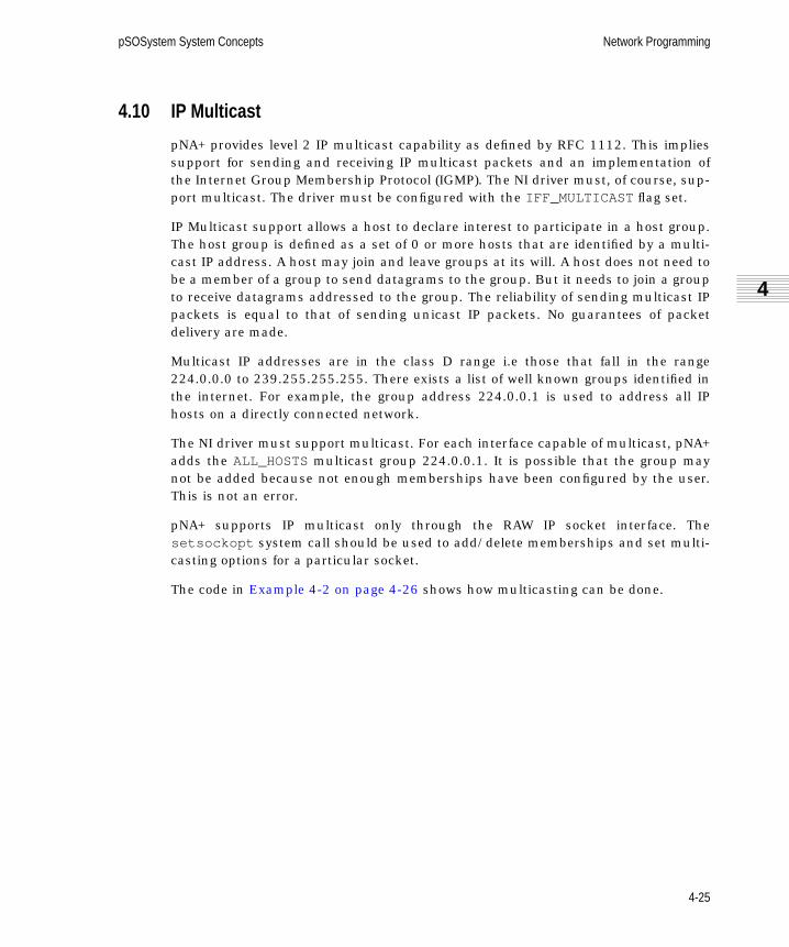
pSOSystem System Concepts Network Programming
4
sc.book Page 25 Friday, January 8, 1999 2:07 PM
4.10 IP Multicast
pNA+ provides level 2 IP multicast capability as defined by RFC 1112. This impliessupport for sending and receiving IP multicast packets and an implementation ofthe Internet Group Membership Protocol (IGMP). The NI driver must, of course, sup-port multicast. The driver must be configured with the IFF_MULTICAST flag set.
IP Multicast support allows a host to declare interest to participate in a host group.The host group is defined as a set of 0 or more hosts that are identified by a multi-cast IP address. A host may join and leave groups at its will. A host does not need tobe a member of a group to send datagrams to the group. But it needs to join a groupto receive datagrams addressed to the group. The reliability of sending multicast IPpackets is equal to that of sending unicast IP packets. No guarantees of packetdelivery are made.
Multicast IP addresses are in the class D range i.e those that fall in the range224.0.0.0 to 239.255.255.255. There exists a list of well known groups identified inthe internet. For example, the group address 224.0.0.1 is used to address all IPhosts on a directly connected network.
The NI driver must support multicast. For each interface capable of multicast, pNA+adds the ALL_HOSTSmulticast group 224.0.0.1. It is possible that the group maynot be added because not enough memberships have been configured by the user.This is not an error.
pNA+ supports IP multicast only through the RAW IP socket interface. Thesetsockopt system call should be used to add/delete memberships and set multi-casting options for a particular socket.
The code in Example 4-2 on page 4-26 shows how multicasting can be done.
4-25

Network Programming pSOSystem System Concepts
sc.book Page 26 Friday, January 8, 1999 2:07 PM
EXAMPLE 4-2: Code for Doing Multicasting
/* a multicast interface IP address 128.0.0.1 */#define MY_IP_ADDR 0x80000001
{int s;char loop;struct ip_mreq ipmreq;struct ip_mreq_intf ipmreq_intf;struct rtentry rt;struct sockaddr_in sin;char Buffer[1000];
#define satosin(sa) ((struct sockaddr_in *)(sa))
/* open a RAW IP socket */s = socket(AF_INET, SOCK_RAW, 100);
/* Add a default Multicast Route for Transmission */satosin(&rt.rt_dst)->sin_family = AF_INET;satosin(&rt.rt_dst)->sin_addr.s_addr = htonl(0xe0000000);satosin(&rt.rt_gateway)->sin_family = AF_INET;satosin(&rt.rt_gateway)->sin_addr.s_addr = htonl(MY_IP_ADDR);rt.rt_netmask = htonl(0xff000000);rt.rt_flags = RTF_MASK;ioctl(s, SIOCADDRT, (char *)&rt));
/* * Add a group membership on the default interface defined above */ipmreq.imr_mcastaddr.s_addr = htonl(0xe0000040);ipmreq.imr_interface.s_addr = htonl(INADDR_ANY);setsockopt(s, IPPROTO_IP, IP_ADD_MEMBERSHIP, (char *)&ipmreq, sizeof(struct ip_mreq)));
/* Disable loopback of multicast packets */loop = 0;setsockopt(s, IPPROTO_IP, IP_MULTICAST_LOOP, (char *)&loop, sizeof(char));/* Send a multicast packet */sin.sin_addr.s_addr = htonl(0xe00000f0);sin.sin_family = AF_INET;sendto(s, Buffer, 1000, 0, &sin, sizeof(sin));
/* Receive a multicast packet */recv(s, Buffer, 1000, 0);
4-26

pSOSystem System Concepts Network Programming
4
sc.book Page 27 Friday, January 8, 1999 2:07 PM
/* * Drop a group membership on the default interface defined * above */ipmreq.imr_mcastaddr.s_addr = htonl(0xe0000040);ipmreq.imr_interface.s_addr = htonl(INADDR_ANY);setsockopt(s, IPPROTO_IP, IP_DROP_MEMBERSHIP, (char *)&ipmreq, sizeof(struct ip_mreq)));
/* Add a group membership on interface number 1 this option is used for unnumbered interfaces for which the local IP address is unknown */ipmreq_intf.imrif_multiaddr.s_addr = htonl(0xe0000040);ipmreq_intf.imrif_ifno = 1;setsockopt(s, IPPROTO_IP, IP_ADD_MEMBERSHIP_INTF, (char*)&ipmreq_intf, sizeof(struct ip_mreq_intf)));
/* Drop the group membership added above on interface number 1 */ipmreq_intf.imrif_multiaddr.s_addr = htonl(0xe0000040);ipmreq_intf.imrif_ifno = 1;setsockopt(s, IPPROTO_IP, IP_DROP_MEMBERSHIP_INTF, (char*)&ipmreq_intf, sizeof(struct ip_mreq_intf)));
}
4.11 Unnumbered Serial Links
pNA+ supports unnumbered serial links as specified in RFC 1716. Assigning aunique IP address to each serial line connected to a host or router can cause an in-efficient use of the scarce IP address space. The unnumbered serial line concept hasbeen proposed to solve this problem. An unnumbered serial line does not have aunique IP address. All unnumbered serial lines connected to a host or router shareone IP address. This single IP address is termed in pNA+ as the Network Node ID.This is equivalent to the RFC's term of Router-ID.
If unnumbered links are to be used, then the pNA+ Network Node ID must be seteither at configuration time or by the ioctl() system call. For PPP and SLIP thisimplies that the source IP address is fixed to be the Network Node ID. pNA+ will theninternally assign the IP address of the serial line to be the Network Node ID. All IPpackets transmitted over this serial line will contain the Network Node ID as thesource address of the packet. An NI is configured as an unnumbered link if theIFF_UNNUMBERED flag is set in ifr_flags .
4-27

Network Programming pSOSystem System Concepts
sc.book Page 28 Friday, January 8, 1999 2:07 PM
4.12 Network Interfaces
The pNA+ component accesses a network by calling a user-provided layer of soft-ware called the Network Interface (NI). The interface between the pNA+ componentand the NI is standard and independent of the network’s physical media or topology;it isolates the pNA+ component from the network’s physical characteristics.
The NI is essentially a device driver that provides access to a transmission medium.(The terms network interface, NI, and network driver are all used interchangeably inthis manual.) A detailed description of the interface between the pNA+ componentand the NI is given in the “Interfaces and Drivers” chapter of the pSOSystemProgrammer’s Reference.
There must be one NI for each network connected to a pNA+ node. In the simplestcase, a node is connected to just one network and will have just one NI. However, anode can be connected to several networks simultaneously and therefore have sev-eral network interfaces. Each NI is assigned a unique IP address.
Each network connection (NI) has a number of attributes associated with it. Theyare as follows:
■ The address of the NI entry point
■ The IP address
■ The maximum transmission unit
■ The length of its hardware address
■ Control flags
■ The network mask
■ Destination IP address (point-to-point links)
The pNA+ component stores these attributes for all of the network interfacesinstalled in your system in the NI Table, discussed in Section 4.12.6 on page 4-31.NI attributes can be modified using ioctl() . The first two attributes are self-explanatory. Maximum transmission units, hardware addresses, control flags, net-work subnet mask, and destination IP address are discussed in the followingsubsections.
4-28

pSOSystem System Concepts Network Programming
4
sc.book Page 29 Friday, January 8, 1999 2:07 PM
4.12.1 Maximum Transmission Units (MTU)
Most networks are limited in the number of bytes that can be physically transmittedin a single transaction. Each NI therefore has an associated maximum transmissionunit (MTU), which is the maximum packet size that can be sent or received. If thesize of a packet exceeds the network’s MTU, the IP layer fragments the packet fortransmission. Similarly, the IP layer on the receiving node reassembles the frag-ments into the original packet.
The minimum MTU allowed by the pNA+ component is 64 bytes. There is no maxi-mum limit. A larger MTU leads to less fragmentation of packets, but usuallyincreases the internal memory requirements of the NI. Generally, an MTU between512 bytes and 2K bytes is reasonable. For example, the MTU for Ethernet is 1500.
4.12.2 Hardware Addresses
In addition to its internet address, every NI has a hardware address. The internetaddress is used by the IP layer, while the hardware address is used by the networkdriver when physically transferring packets on the network. The process by whichinternet addresses are mapped to hardware addresses is called address resolutionand is discussed in Section 4.13.
Unlike an internet address, which is four bytes long, the length of a hardware ad-dress varies depending on the type of network. For example, an Ethernet address is6 bytes while a shared memory address is usually 4 bytes. The pNA+ componentcan support hardware addresses up to 14 bytes in length. The length of a NI’s hard-ware address must be specified.
4.12.3 Flags
Each NI has a set of flags that define optional capabilities, as follows:
IFF_NOARP This is used to enable or disable address resolution (seeSection 4.13).
IFF_BROADCAST This is used to tell the pNA+ component if the NI supportsbroadcasting. If you attempt to broadcast a packet on anetwork with this flag disabled, the pNA+ componentreturns an error.
IFF_EXTLOOPBACK If this is disabled, the pNA+ component ‘‘loops back’’packets addressed to itself. That is, if you send a packet toyourself, the pNA+ component does not call the NI, but thepacket is processed as if it were received externally. If thisflag is enabled, the pNA+ component calls the NI.
4-29

Network Programming pSOSystem System Concepts
sc.book Page 30 Friday, January 8, 1999 2:07 PM
Note that if the ARP flag is enabled, the BROADCASTflag must also be set (seeSection 4.13). Additional flags are provided to control the Network Interface:
4.12.4 Network Subnet Mask
A network can have a network mask associated with it to support subnet address-ing. The network mask is a 32-bit value with ones in all bit positions that are to beinterpreted as the network portion. See Section 4.3.2 for a discussion on subnetaddressing.
IFF_MULTICAST If this is set, the NI is capable of doing multicast (seeSection 4.10 on page 4-25).
IFF_POLL If this is set, the ni_poll service is called by the pSOS+daemon task PNAD. This flag is normally used in conjunc-tion with the pROBE+ debugger.
IFF_POINTTOPOINT If this is set, the NI is a point-to-point interface.
IFF_RAWMEM If this is set, the pNA+ component passes packets to thedriver in the form of mblk (message block) linked lists(see Section 4.14 on page 4-35). Similarly, the driverannounces packets by passing a pointer to the messageblock.
IFF_UNNUMBERED If this is set, the NI is an unnumbered point-to-point link.pNA+ assigns the network node ID as the IP address of thelink (see Section 4.11 on page 4-27).
IFF_UP This flag controls the interface status: up or down. If theflag is set the interface is up; if the flag is not set the inter-face is down.
IFF_INITDOWN This flag must only be specified at the interface initializa-tion time. By default pNA+ sets the interfaces to up statusat initialization. If it is required that the interface be downafter initialization, this flag must be set.
IFF_RECEIVEROFF This flag controls the interface receiving end. If the flag isset, the interface stops receiving packets from the attachednetwork.
IFF_PROMISC This flag controls the promiscuous mode of operation ofthe interface. If the flag is set, the interface runs in promis-cuous mode, and all packets on the attached network arereceived.
4-30

pSOSystem System Concepts Network Programming
4
sc.book Page 31 Friday, January 8, 1999 2:07 PM
4.12.5 Destination Address
In point-to-point networks, two hosts are joined on opposite ends of a network inter-face. The destination address of the companion host is specified in the pNA+ NITable entry DSTIPADDR for point-to-point networks.
4.12.6 The NI Table
The pNA+ component stores the parameters described above for each NI in the NITable. The size of the NI Table is determined by the pNA+ Configuration Table entryNC_NNI, which defines the maximum number of networks that can be connected tothe pNA+ component.
Entries can be added to the NI Table in one of two ways:
1. The pNA+ Configuration Table entry NC_INI contains a pointer to an Initial NITable. The contents of the Initial NI Table are copied to the actual NI Table dur-ing pNA+ initialization.
2. The pNA+ system call add_ni() can be used to add an entry to the NI Tabledynamically, after the pNA+ component has been initialized.
The code segment in Example 4-3 illustrates some NI related ioctl() operations.
EXAMPLE 4-3: Code Illustrating NI-related Operations
{#define satosin(sa) ((struct sockaddr_in *)(sa))#define MAX_BUF 1024
int s, rc;struct ifconf ifc;struct ifreq ifr;char buffer[MAX_BUF];
/* create any type of socket */s = socket(AF_INET, SOCK_DGRAM, 0);
/* get the interface configuration list */ifc.ifc_len = MAX_BUF;ifc.ifc_buf = buffer;rc = ioctl(s, SIOCGIFCONF, (char *)&ifc);
/* * change the IP address of the pNA+ interface 1 * to 192.0.0.1
4-31

Network Programming pSOSystem System Concepts
sc.book Page 32 Friday, January 8, 1999 2:07 PM
*/ifr.ifr_ifno = 1;satosin(&ifr.ifr_addr)->sin_family = AF_INET;satosin(&ifr.ifr_addr)->sin_addr.s_addr = htonl(0xc0000001);rc = ioctl(s, SIOCSIFADDR, (char *)&ifr);
/* * change the destination IP address of a point-point * interface (pNA+ interface 2) such as a PPP line to * 192.0.0.1 */ifr.ifr_ifno = 2;satosin(&ifr.ifr_addr)->sin_family = AF_INET;satosin(&ifr.ifr_dstaddr)->sin_addr.s_addr = htonl(0xc0000001);rc = ioctl(s, SIOCSIFDSTADDR, (char *)&ifr);
/* * change the status of the interface number 1 to down. * this must be done in 2 steps, get the current interface * flags, turn the UP flag off and set the interface flags. */ifr.ifr_ifno = 1;rc = ioctl(s, SIOCGIFFLAGS, (char *)&ifr);ifr.ifr_ifno = 1;ifr.ifr_flags &= ~IFF_UP;rc = ioctl(s, SIOCSIFFLAGS, (char *)&ifr);
/* close the socket */close(s);}
4.13 Address Resolution and ARP
Every NI has two addresses associated with it — an internet address and a hard-ware address. The IP layer uses the internet address, while the network driver usesthe hardware address. The process by which an internet address is mapped to ahardware address is called address resolution.
In many systems, address resolution is performed by the network driver. The ad-dress resolution process, however, can be difficult to implement. Therefore, to sim-plify the design of network drivers, the pNA+ component provides the capability ofresolving addresses internally. To provide maximum flexibility, this feature can beoptionally turned on or off, so that, if necessary, address resolution can still be han-dled at the driver level. This can be used for such applications as implementing ATMARP.
4-32

pSOSystem System Concepts Network Programming
4
sc.book Page 33 Friday, January 8, 1999 2:07 PM
The pNA+ component does the following steps when performing address resolution:
1. The pNA+ component examines the NI flags (see Section 4.12.3) to determine ifit should handle address resolution internally. If not (i.e. the ARP flag is dis-abled), the pNA+ component passes the internet address to the network driver.
2. If the ARP flag is enabled, the pNA+ component searches its ARP Table (seeSection 4.13.1) for an entry containing the internet address. If an entry isfound, the corresponding hardware address is passed to the NI.
3. If the internet address is not found in the ARP Table, the pNA+ component usesthe Address Resolution Protocol (see Section 4.13.2) to obtain the hardware ad-dress dynamically.
4.13.1 The ARP Table
The pNA+ component maintains a table called the ARP Table for obtaining a hard-ware address, given an internet address. This table consists of <internet address,hardware address> tuples.
The ARP Table is created during pNA+ initialization; the pNA+ Configuration Tableentry NC_NARPspecifies its size. Entries can be added to the ARP Table in one ofthree ways:
1. An Initial ARP Table can be supplied. The pNA+ Configuration Table entryNC_IARP contains a pointer to an Initial ARP Table. The contents of the InitialARP Table are copied to the actual ARP Table during pNA+ initialization.
2. Internet-to-hardware address associations can be determined dynamically bythe ARP protocol. When the pNA+ component uses ARP to dynamically deter-mine an internet-to-hardware address mapping, it stores the new <internetaddress, hardware address> tuple in the ARP Table. This is the normal way thatthe ARP Table is updated. The next section explains how ARP operates.
3. ARP Table entries can be added dynamically by using ioctl() .The code seg-ment in Example 4-4 on page 4-34 illustrates the usage of the various ARPioctl() calls.
4-33

Network Programming pSOSystem System Concepts
sc.book Page 34 Friday, January 8, 1999 2:07 PM
EXAMPLE 4-4: Code Illustrating ARP Calls
{#define satosin(sa) ((struct sockaddr_in *)(sa))int s, rc;struct arpreq ar;char *ha;
/* create any type of socket */s = socket(AF_INET, SOCK_DGRAM, 0);
/* * get the arp entry corresponding to the internet * host address 128.0.0.1 */satosin(&ar.arp_pa)->sin_family = AF_INET;satosin(&ar.arp_pa)->sin_addr.s_addr = htonl(0x80000001);ar.arp_ha.sa_family = AF_UNSPEC;rc = ioctl(s, SIOCGARP, (char *)&ar);
/* * set a permanent but not publishable arp entry corresponding * to the internet host address 128.0.0.1. If the entry * exists it will be modified. Set the ethernet address to * aa:bb:cc:dd:ee:ff */satosin(&ar.arp_pa)->sin_family = AF_INET;satosin(&ar.arp_pa)->sin_addr.s_addr = htonl(0x80000001);ar.arp_ha.sa_family = AF_UNSPEC;bzero(ar.arp_ha.sa_data, 14);ha = ar.arp_ha.sa_data;ha[0] = 0xaa; ha[1] = 0xbb; ha[2] = 0xcc;ha[3] = 0xdd; ha[4] = 0xee; ha[5] = 0xff;ar.arp_flags = ATF_PERM;rc = ioctl(s, SIOCSARP, (char *)&ar);
/* * delete the arp entry corresponding to the internet * host address 128.0.0.1 */satosin(&ar.arp_pa)->sin_family = AF_INET;satosin(&ar.arp_pa)->sin_addr.s_addr = htonl(0x80000001);ar.arp_ha.sa_family = AF_UNSPEC;rc = ioctl(s, SIOCDARP, (char *)&ar);
/* close the socket */close(s);}
4-34

pSOSystem System Concepts Network Programming
4
sc.book Page 35 Friday, January 8, 1999 2:07 PM
4.13.2 Address Resolution Protocol (ARP)
The pNA+ component uses the Address Resolution Protocol (ARP) to determine thehardware address of a node dynamically, given its internet address. ARP operates asfollows:
1. A sender, wishing to learn the hardware address of a destination node, preparesand broadcasts an ARP packet containing the destination internet address.
2. Every node on the network receives the packet and compares its own internetaddress to the address specified in the broadcasted packet.
3. If a receiving node has a matching internet address, it prepares and transmitsto the sending node an ARP reply packet containing its hardware address.
ARP can be used only if all nodes on the network support it. If your network consistsonly of pNA+ nodes, this requirement is of course satisfied. Otherwise, you mustmake sure that the non-pNA+ nodes support ARP. ARP was originally developed forEthernet networks and is usually supported by Ethernet drivers. Networks based onother media might or might not support ARP.
The pNA+ component treats internet packets differently than ARP packets. WhenpNA+ calls an NI, it provides a packet type parameter, which is either IP or ARP.Similarly, when the pNA+ component receives a packet, the NI must also return apacket type. All network drivers that support ARP must have some mechanism forattaching this packet type to the packet. For example, Ethernet packets containtype fields. For NIs that do not support ARP, the packet type parameter can beignored on transmission, and set to IP for incoming packets.
4.14 Memory Management
As packets move across various protocol layers in the pNA+ component, they aresubject to several data manipulations, including:
■ Addition of protocol headers
■ Deletion of protocol headers
■ Fragmentation of packets
■ Reassembly of packets
■ Copying of packets
4-35

Network Programming pSOSystem System Concepts
sc.book Page 36 Friday, January 8, 1999 2:07 PM
The pNA+ component is designed with specialized memory management so thatsuch manipulations can be done optimally and easily.
The pNA+ component allows configuration of its memory management data struc-tures via the pNA+ Configuration Table. These structures are critical to its perfor-mance; hence, understanding the basics of pNA+ memory management is crucial toconfiguring your system optimally.
The basic unit of data used internally by the pNA+ component is called a message.Messages are stored in message structures. A message structure contains one ormore message block triplets, linked via a singly-linked list. Each message block trip-let contains a contiguous block of memory defining part of a message. A completemessage is formed by linking such message block triplets in a singly-linked list.
Each message block triplet contains a Message Block, a Data Block, and a Buffer.Figure 4-3 illustrates the message block triplet.
A message block contains the characteristics of the partial message defined by themessage block triplet. A data block contains the characteristics of the buffer towhich it points. A buffer is a contiguous block of memory containing data.
A data block may be contained in several message block triplets. However, there is aone-to-one correspondence between data blocks and buffers. The C language defini-tions of the data structures for message blocks and data blocks are in the headerfile <pna.h> .
Message Block
Data Block
Data Buffer
Next Message
dblk_t
mblk_t
FIGURE 4-3 Message Block Triplet
4-36

pSOSystem System Concepts Network Programming
4
sc.book Page 37 Friday, January 8, 1999 2:07 PM
Figure 4-4 on page 4-38 illustrates a complete message formed by a linked list ofmessage block triplets.
The basic unit of transmission used by protocol layers in the pNA+ component is apacket. A packet contains a protocol header and the data it encapsulates. Each pro-tocol layer tags a header to the packet and passes it to the lower layer for transmis-sion. The lower layer in turn uses the packet as encapsulated data and tags itsprotocol header and passes it to its lower layer. Packets are stored in the form ofmessages.
The buffers in the pNA+ component are used to store data, protocol headers, andaddresses. Data is passed into the pNA+ component via two interfaces. At the userlevel, data is passed via the send() , sendto() and sendmsg() service calls. At theNI interface, data is passed via the “Announce Packet” call (See Section 4.12 onpage 4-28).
The pNA+ component allocates a message block triplet and copies data from theexternal buffer to the buffer associated with the triplet. The message is then passedto the protocol layers for further manipulation. As the data passes through variousprotocol layers, additional message block triplets are allocated to store the protocolheaders and are linked to the message. The pNA+ component also allocates tempo-rary message block triplets to store socket addresses during pNA+ service calls.
As the messages pass through the protocol layers, they are subjected to variousdata manipulations (copying, fragmentation, and reassembly). For instance, whenpreparing a packet for transmission, the TCP layer makes a copy of the packet fromthe socket buffer, tags a TCP header, and passes the packet to the IP layer. Simi-larly, the IP layer fragments packets it receives from the transport layer (TCP, UDP)to fit the MTU of the outgoing Network Interface.
pNA+ memory management is optimized to perform such operations efficiently andmaximize performance by avoiding physical copying of data. For instance, copyingof message block triplets is achieved by allocating a new message block, associatingit with the original data block, and increasing the reference count to the originaldata block. This avoids costly data copy operations.
4.14.1 Memory Management Schemes
The two types of memory management schemes for handling packet buffers are:
■ Centralized-memory pool scheme — Contains the memory required by packettransmission, packet reception, and internal processing that are allocated froma single memory pool. The advantage of a centralized-memory scheme is that itefficiently utilizes the available memory resource.
4-37

Network Programming pSOSystem System Concepts
sc.book Page 38 Friday, January 8, 1999 2:07 PM
b_datap
b_rptr
b_wptr
b_cont
Message Block 1 Message Block 2 Message Block 3
Data Block 1 Data Block 2
db_base
db_lim
db_base
b_cont
b_rptr
b_wptr
b_rptr
b_wptr
b_datapb_datap
Data BufferData Buffer
mblk_t
mblk_t mblk_t
dblk_t dblk_t
db_lim
FIGURE 4-4 Message Block Linkage
4-38
pSOSystem System Concepts Network Programming
4
sc.book Page 39 Friday, January 8, 1999 2:07 PM
■ Distributed-memory pool scheme — Contains the buffer pools that are distrib-uted amongst packet transmission, packet reception, and system processing.
Each scheme offers certain benefits and trade-offs in a system design. Some ofthe advantages of distributed-memory schemes are:
● Deadlock avoidance — The major drawback to the centralized-memory poolscheme is the usage overrun problem. As an example to illustrate thisscenario, consider a system that uses a centralized-memory pool, with mul-tiple TCP connections established and each one is used as a transmitter.
At some point, memory utilization can reach an undesired level of 100%capacity. Consequently, when TCP ACK (Transmission Control ProtocolAcknowledgment) packets are received, these packets must be discardeddue to a lack of processing buffers. However, ACK packets triggers the de-allocation of memory resources occupied by the TCP packets, which aremaintained on the retransmission queues; thus, making more memoryresources available. This deadlock situation can be recovered only througha TCP connection timeout termination. This can be avoided by a distributedmemory pool scheme.
● Configuration accuracy — The distributed-memory scheme allows thememory configuration to reflect on the nature of the embedded application.If the memory configuration accurately represents the characteristics ofhow the application will behave, the more efficiently the memory resourceswill be utilized. This is the reason why the advantage of efficient memoryutilization as observed in a centralized-memory scheme can be alsoachieved in a distributed-memory pool scheme as well.
Also, a distributed-memory scheme can be applied to an embedded systemto study the resource demand and resource utilization characteristics. Theuser can use the results of such a study as feedback into the design of acentralized - memory scheme system.
● Ease of debugging — The centralized-memory pool scheme exhibits unpre-dictable behaviors when memory resource utilization reaches 100% capac-ity. It is both tedious and difficult to investigate the cause of the problemwhen the centralized memory scheme is applied in the system. In regards toa distributed-memory scheme, each memory resource component can beadjusted individually to discover or to precisely analyze the causes of thesymptoms exhibited.
4-39

Network Programming pSOSystem System Concepts
sc.book Page 40 Friday, January 8, 1999 2:07 PM
The main disadvantage of a distributed memory pool scheme is its requirement onthe user to have detailed and accurate knowledge about the application’s memoryusage characteristics. Inappropriate configuration can reduce the available memoryin a particular pool. Thus, this reduces the application’s performance if the applica-tion heavily relies on this memory pool.
pNA+ supports both schemes. See pSOSystem Programmer’s Reference, Chapter 4,Configuration Tables, for additional details about the pNA+ configuration.
4.15 Memory Configuration
During the initialization of the pNA+ component various memory structures are cre-ated and initialized. The initialization sequence creates message blocks, datablocks, and data buffers of multiple sizes. The number of each is configurable in thepNA+ Configuration Table. the pNA+ component provides entries in the configura-tion table to specify the number of message blocks and data buffers. Because thereis a one-to-one relationship between data blocks and data buffers, the pNA+ compo-nent allocates a data block for every buffer configured in the system.
The pNA+ memory configuration is critical to its performance. Configuring too fewbuffers or wrong sizes leads to reduced performance. Configuring too many bufferswastes memory. Optimal performance can be achieved empirically by tuning the fol-lowing configurable elements:
■ Number of message blocks
■ Buffer configuration
■ MTU-size buffers
■ Various size buffers
■ Zero-size buffers
The following sections give general configuration guidelines.
4.15.1 Buffer Configuration
Buffer configuration is specified via the nc_bcfg element in the pNA+ ConfigurationTable (See the “Configuration Tables” chapter of the pSOSystem Programmer’s Refer-ence). It allows you to configure application-specific buffer sizes into the system.Two attributes are associated with a buffer configuration: buffer size and the num-ber of buffers.
4-40

pSOSystem System Concepts Network Programming
4
sc.book Page 41 Friday, January 8, 1999 2:07 PM
The pNA+ component copies data into its internal buffers via two interfaces. It cop-ies data from the user buffers to its internal buffers during send() , sendto() , andsendmsg() service calls. It copies data from the NI buffers to its internal buffersduring “Announce Packet’’ calls.
The pNA+ component allows buffers of multiple sizes to be configured into the sys-tem. In order to allocate a buffer to copy data, it first selects the buffer size, usingthe following best-fit algorithm:
1. The pNA+ component first tries to find an exact match for the data buffer.
2. If there is no such buffer size available, the pNA+ component searches for thesmallest sized buffer that can contain the requested size.
3. If there is none, the pNA+ component selects the maximum buffer size config-ured.
Once a size is selected, the pNA+ component checks for a free buffer from theselected size’s buffer list. If none are available, the pNA+ component blocks thecaller on a blocking call, or returns null on a non-blocking call. If the size of thebuffer is not sufficient to copy all of the data, the pNA+ component copies the datainto multiple buffers.
For optimal configuration, the pNA+ component should always find an exact matchwhen doing buffer size selection. Thus, the configuration should have buffer sizesequal to the MTU of the NI’s configured in the pNA+ component to satisfy therequirement at the NI interface, and buffer sizes equal to the user buffer sizes spec-ified in the send() , sendto() , and sendmsg() service calls to satisfy user inter-face requirements. The number of buffers to be configured for each size depends onthe socket buffer size and incoming network traffic.
pNA+ flexible memory configuration provides multiple buffer sizes. However, 128-byte and zero-size buffers have special meanings. 128-byte buffers are used inter-nally by the pNA+ component for storing protocol headers and for temporary usage.These buffers must always be configured for pNA+ to function. Zero-size buffers areused to create message block triplets with externally specified data buffers (SeeSection 4.16 on page 4-45, and the pna_esballoc() call description in pSOSystemSystem Calls).
4-41

Network Programming pSOSystem System Concepts
sc.book Page 42 Friday, January 8, 1999 2:07 PM
MTU-Size Buffers
When a non-zero copy NI is pNA+ configured, data is copied from the NI buffers topNA+ internal buffers. Hence, it is optimal to have MTU-size buffers configured inthe system. The number of buffers that should be configured depends on the incom-ing network traffic on that NI.
Service-Call-Size Buffers
Data is copied from user buffers to pNA+ internal data buffers during send() ,sendto() , and sendmsg() service calls. For optimal performance, the pNA+ com-ponent should be configured with buffer sizes specified in the service calls. The opti-mal number of buffers depends on the buffer size of the socket.
128-Byte Buffers
The pNA+ component uses 128-byte buffers to store protocol headers and ad-dresses. The number of protocol headers allocated at any given time depends on thenumber of packets sent or received simultaneously by the protocol layers in thepNA+ component. The number of packets sent or received by the pNA+ componentvaries with the number of active sockets and with socket buffer size. The number ofpackets that can exist per active socket is the socket buffer size divided by the MTUof the outgoing NI. pNA+ service calls also use 128-byte buffers for temporary pur-poses; they use a maximum of three buffers per call.
Zero-Size Buffers
Zero-size buffers are used during pna_esballoc service calls to attach externallysupplied user buffers to a message block and a data block. When zero-size buffersare specified, the pNA+ component allocates only a data block; that is, the associ-ated buffer is not allocated.
The optimal number of zero-size buffers to be configured depends on the number ofexternally specified buffers that can be attached to pNA+ message blocks; that is,the number of times pna_esballoc is used. (For more details, see Section 4.16 onpage 4-45.)
4-42

pSOSystem System Concepts Network Programming
4
sc.book Page 43 Friday, January 8, 1999 2:07 PM
4.15.2 Message Blocks
The pNA+ memory manager is highly optimized for data copy and fragmentation.During these operations, the pNA+ component allocates an additional messageblock and reuses the original data block and buffer. The number of pNA+ copy orfragmentation operations per buffer depends on the size of the buffer and on theMTU size of the NI’s configured in the system.
The maximum number of fragments for buffers of sizes less than the smallest MTUis two, and the maximum number of fragments for all other buffers is the buffer sizedivided by the MTU.
The number of message blocks configured in the system should equal the totalnumber of fragments that can be formed from the buffers configured in the system.In most cases, it is sufficient to configure the total number of message blocks to betwice the total number of buffers configured in the system.
4.15.3 Tuning the pNA+ Component
The pNA+ component also provides statistics for buffer and message block usage viathe ioctl() service call. The SIOCGDBSTAT command can be used to returnbuffer usage, and SIOCGMBSTAT can be used to get message block usage.
These commands provide information on the number of times tasks waited for abuffer, the number of times a buffer was unavailable, the number of free buffers,and the total number of buffers configured in the system. You can use this informa-tion to tweak the message block and data buffer configuration.
The code in Example 4-5 on page 4-44 illustrates the use of the SIOCGDBSTATandthe SIOCGMBSTAT ioctl() options.
4-43

Network Programming pSOSystem System Concepts
sc.book Page 44 Friday, January 8, 1999 2:07 PM
EXAMPLE 4-5: Code Illustrating SIOCGDBSTAT and SIOCGMBSTAT ioctl() Options
{int i, s, rc;int buffer_types, size;struct mbstat mbstat;struct dbreq dbr;struct dbstat *dbs;char *buffer;
/* create a socket */s = socket(AF_INET, SOCK_DGRAM, 0);
/* get the message block statistics */ioctl(s, SIOCGMBSTAT, (char *)&mbstat);
/* print out the message buffer statistics */printf("No of Buffer classes = %ld\n", mbstat.mb_bufclasses);printf("No of mblks = %ld\n", mbstat.mb_mblks);printf("No of free mblks = %ld\n", mbstat.mb_free);printf("Times waited for mblks = %ld\n", mbstat.mb_wait);printf("Times failed to get mblks = %ld\n\n", mbstat.mb_drops);
/* allocate a buffer large enough to store all the data buffer statistics */buffer_types = mbstat.mb_bufclasses;size = buffer_types*sizeof(struct dbstat);buffer = malloc(size);
/* fill in the dbr structure */dbr.size = sizedbr.dsp = (struct dbstat *)buffer;rc = ioctl(s, SIOCGDBSTAT, (char *)&dbr);
/* the actual number of buffer types that pNA+ could fit in the provided buffer is returned in the dbr structure */buffer_types = dbr.size/sizeof(struct dbstat);
/* loop and print all the buffer types and their statistics */dbs = dbr.dsp;for (i=0; i < buffer_types; i++) { printf("Buffer Size = %ld\n", dbs[i].db_size); printf(" No data blocks = %ld\n", dbs[i].db_dblks); printf(" No of free = %ld\n", dbs[i].db_free); printf(" Times waited for dblks = %ld\n", dbs[i].db_wait); printf(" Times failed to get dblks = %ld\n\n", dbs[i].db_drops); }
4-44

pSOSystem System Concepts Network Programming
4
sc.book Page 45 Friday, January 8, 1999 2:07 PM
4.16 Zero Copy Options
Copying data is an expensive operation in any networking system. Hence, eliminat-ing it is critical to optimal performance. The pNA+ component performs data copy atits two interfaces. It copies data from the user buffer to pNA+ internal buffers dur-ing send() , sendto() , and sendmsg() service calls, and vice versa duringrecv() , recvfrom() , and recvmsg() calls. A data copy is performed between theNI and pNA+ buffers when data is exchanged.
Because the pNA+ memory manager is highly optimized to eliminate data copy, datais copied only at the interfaces during data transfers. In order to maximize perfor-mance, the pNA+ component provides options to eliminate data copy at its inter-faces, as well. These options are referred to as “zero copy” operations. The pNA+component extends the standard Berkeley socket interface at the user level and pro-vides an option at the NI level to support zero copy operations.
Zero copy is achieved in the pNA+ component by providing a means of exchangingdata at interfaces via message block triplets and by enabling access to its memorymanagement. The zero copy operations provided at the interfaces are independentof each other; that is, an application can choose either one, or both. In most cases,the NI interface is optimized to perform zero copy, while retaining the standardinterface at the socket level.
4.16.1 Socket Extensions
The sendto() , send() , recv() , and recvfrom() service calls are extended tosupport the zero copy option. An option is provided in the calls allowing data to beexchanged via message block triplets. An additional flag (MSG_RAWMEM) is providedin these service calls. When the flags parameter in these service calls is set toMSG_RAWMEM, the buf parameter contains a pointer to a message block triplet. (Seethese service call descriptions in pSOSystem System Calls.)
When the zero copy option is not used, a buffer always remains in the control of itsowner. For example, during a send() call, the address of the buffer containing datato be sent is passed to the pNA+ component. As soon as the call returns, the buffercan be reused or de-allocated by its owner. The pNA+ component has copied thedata into its internal buffers.
When the zero copy option is used, control of the buffer triplet passes to the pNA+component. When the pNA+ component finishes using the message block triplet, thetriplet is freed. Similarly, on a recv() call, control of the buffer passes to the appli-cation, which is responsible for freeing the message block triplet.
4-45

Network Programming pSOSystem System Concepts
sc.book Page 46 Friday, January 8, 1999 2:07 PM
When zero copy is used with non-blocking sockets there is a possibility that a sendcall may return after sending a part of the whole message. In this case the user mayresend the remaining part of the buffer on the next send call using the same mes-sage block triplet. The message block points to the remaining part of the message.Internally pNA+ keeps a reference to the buffer until the data is sent.
Four service calls are provided to access pNA+ memory management. They are asfollows:
4.16.2 Network Interface Option
The pNA+ network interface definition supports data exchange between the pNA+component and an NI via message block triplets. If the RAWMEMflag is set in the NIflags, it indicates that the interface supports the zero copy operation, and theexchange of data between NI and the pNA+ component is in the form of messageblock triplets.
The pointers to the pna_allocb() , pna_freeb() , pna_freemsg() , andpna_esballoc() functions are passed to the NI driver during its ni_init() func-tion call. (See Section 4.12 on page 4-28.) These functions are used by the NI to gainaccess to pNA+ memory management routines.
4.16.3 Zero Copy User Interface Example
The code in Example 4-6 illustrates the usage of the zero copy interface at the userapplication level. The pnabench demo application is also a good example of the zerocopy features in pNA+.
pna_allocb() allocates a message block triplet that contains a databuffer of the size passed in as a parameter. The data bufferis internal to the pNA+ component.
pna_freeb() frees a single message block triplet.
pna_freemsg() frees a message.
pna_esballoc() associates a message block and a data block with an exter-nally specified buffer. pna_esballoc() returns a pointerto a message block triplet that contains a message blockand a data block allocated by the pNA+ component. Thedata buffer in the triplet is passed in as a parameter to thecall.
4-46

pSOSystem System Concepts Network Programming
4
sc.book Page 47 Friday, January 8, 1999 2:07 PM
EXAMPLE 4-6: Code Illustrating Use of Zero Copy Interface
zero_copy_ex(){int rc, s, arg, err;unsigned char buffer[200];mblk_t *mb, *mb1, *mb2;struct sockaddr_in peeraddr_in;frtn_t freefn;void ufreefn();
/* create a TCP socket */s = socket(AF_INET, SOCK_STREAM, 0);
memset((char *)&peeraddr_in, 0, sizeof(struct sockaddr_in));peeraddr_in.sin_family = AF_INET;peeraddr_in.sin_addr.s_addr = htonl (HOST_IP);peeraddr_in.sin_port = htons (SERVER_PORT);connect(s, &peeraddr_in, sizeof(struct sockaddr_in));
/* make the socket non-blocking */arg = 1;ioctl(s, FIONBIO, (char *)&arg);
/* allocate a 200 byte message block triplet from pNA+ buffers */mb = pna_allocb(200, 0);if (mb == 0)error(“pna_allocb() error: “);
/* Advance the message blocks write pointer so pNA will know how muchdata is in the data area of the message block. Note that after thesend calls succeeds pNA+ has ownership of the data. */mb->b_wptr += 200;mb->b_cont = 0;
rc = 200;while (rc != 0) { err = send(s, (char *)mb, rc, MSG_RAWMEM); if (err == -1) { /* Since only one mblock needs to be freed it is ok to call pna_freeb. But pna_freemsg will also work for this case */
pna_freeb(mb); break; }
4-47

Network Programming pSOSystem System Concepts
sc.book Page 48 Friday, January 8, 1999 2:07 PM
/* In the event that TCP was unable to queue up *all* the data, the remaining data should be sent out again later. Once again a send can be called with the same mblock. pNA+ will update the read pointer in cases of partial sends. Note that partial sends are
possible with non-blocking sockets because there may not be enough space in the send buffer for the data to be queued at once */ rc -= err; }
/* mark the socket as blocking */arg = 0;ioctl(s, FIONBIO, (char *)&arg);
/* Create a message out of a pNA+ allocated buffer and a user buffer */
/* Allocate a pNA+ buffer */mb1 = pna_allocb(200, 0);if (mb1 == 0) error(“pna_allocb() error: “);
/* Allocate a user buffer - assign a free function */freefn.free_func = ufreefn;freefn.free_arg = buffer;mb2 = pna_esballoc(buffer, 200, 0, &freefn);if (mb2 == 0) error(“pna_esballoc() error: “);
/* Link the mblocks into one message */mb1->b_cont = mb2;mb2->b_cont = 0;
/* This time the entire data should be buffered in the TCP send queueat once. The task could of course block because the socket is set toblocking mode */err = send(s, (char *)mb1, rc, MSG_RAWMEM);
/* Receive incoming data on the socket - maximum of 400 bytes - thetask may block till 400 bytes of data is received */err = recv(s, (char *)&mb, 400, MSG_RAWMEM);
/* process the data in the received message ... */
/* The application needs to free the mblocks because pNA+ transferredownership of the mblocks to the application. The mb data buffer willbe freed to the pNA+ buffer pool */pna_freemsg(mb);}
4-48

pSOSystem System Concepts Network Programming
4
sc.book Page 49 Friday, January 8, 1999 2:07 PM
/* Nothing to do for the free function since the buffer was allocatedoff the stack. Normally this would free a dynamically allocatedbuffer */voidufreefn(buf)unsigned char *buf;{
return;}
4.17 Internet Control Message Protocol (ICMP)
ICMP is a control and error message protocol for IP. It is layered above IP for inputand output, but it is really part of IP. ICMP can be accessed through the raw socketfacility. The pNA+ component processes and generates ICMP messages in responseto ICMP messages it receives.
ICMP can be used to determine if the pNA+ component is accessible on a network.For example, some workstations (such as SUN) provide a utility program calledping, which generates ICMP echo requests and then waits for corresponding repliesand displays them when received. The pNA+ component responds to the ICMP mes-sages sent by ping.
ICMP supports 11 unique message types, with each reserved to designate specific IPpacket or network status characteristics, as shown in Table 4-3:
TABLE 4-3 Message Types
TYPE CODE DESCRIPTION
0 0 ECHO REPLY. This type is used to test/verify that the desti-nation is reachable and responding. The ping utility relies onthis ICMP message type.
3
012345
DESTINATION UNREACHABLE. This type is generated whenan IP datagram cannot be delivered by a node. This type isfurther delineated by ancillary codes defined as follows:
Network unreachable.Host unreachable.Protocol unreachable.Port unreachable.Fragmentation needed but don’t-fragment bit set.Source route failed.
4-49

Network Programming pSOSystem System Concepts
sc.book Page 50 Friday, January 8, 1999 2:07 PM
4.18 Internet Group Management Protocol (IGMP)
IGMP is used by IP nodes to report their host group memberships to any immedi-ately-neighboring multicast routers. Like ICMP, IGMP is an integral part of IP. It isimplemented by all nodes conforming to the Level 2 IP Multicasting specification inRFC 1112. IGMP messages are encapsulated in IP datagrams, with an IP protocolnumber of 2. IGMP can be accessed through the RAW IP socket facility.
4 0 SOURCE QUENCH. This type is generated when buffers areexhausted at an intermediary gateway or end-host.
5
0123
REDIRECT. This type is generated for a change of route.
Redirect for network.Redirect for host.Redirect for type-of-service and network.Redirect for type-of-service and host.
8 0 ECHO REQUEST. This type is used to test/ verify that thedestination is reachable and responding. The ping utility re-lies on this ICMP message type.
11
01
TIME EXCEEDED FOR DATAGRAM. This type is generatedwhen the datagram's time to live field has exceeded its limit.
Time-to-live equals 0 during transit.Time-to-live equals 0 during reassembly.
12 0 PARAMETER PROBLEM: IP header bad.
13 0 TIMESTAMP REQUEST. This type is generated to request atimestamp.
14 0 TIMESTAMP REPLY.
17 0 ADDRESS MASK REQUEST. This type is sent to obtain asubnet address mask.
18 0 ADDRESS MASK REPLY.
TABLE 4-3 Message Types (Continued)
TYPE CODE DESCRIPTION
4-50

pSOSystem System Concepts Network Programming
4
sc.book Page 51 Friday, January 8, 1999 2:07 PM
Two types of IGMP messages are of concern to nodes, as shown in Table 4-4:
4.19 NFS Support
The pNA+ component can be used in conjunction with the pHILE+ component andthe pRPC+ subcomponent to offer NFS support. To support NFS, the pNA+ compo-nent allows you to assign a host name to your pNA+ system, and a user ID andgroup ID to each task. The host name and user and group IDs are used whenaccessing NFS servers. Every task that uses NFS services must have a user ID and agroup ID. These values are used by an NFS server to recognize a client task andgrant or deny services based on its identity. Refer to your host system (NFS server)documentation for a further discussion of NFS protection mechanisms.
The pNA+ Configuration Table entry NC_HOSTNAMEis used to define the host name.This entry points to a null terminated string of up to 32 characters, which containsthe host name for the node.
The pNA+ Configuration Table entries NC_DEFUIDand NC_DEFGIDcan be used todefine default values for a task's user ID and group ID, respectively. Subsequent totask creation, the system calls set_id() and get_id() can be used to change orexamine a task's user and group ID. Note that similar system calls [setid_u() andgetid_u() ] are provided by the pHILE+ component. Integrated Systems recom-mends, however, that you use the set_id() and get_id() system calls providedin the pNA+ component for future compatibility.
TABLE 4-4 IGMP Message
TYPE DESCRIPTION
1 HOST MEMBERSHIP QUERY. Multicast routers send Host Member-ship Query messages to discover which host groups have memberson their attached local networks. Queries are addressed to theALL_HOSTS group (address 224.0.0.1).
2 HOST MEMBERSHIP REPORT. Hosts respond to a Query by gener-ating Host Membership Reports reporting each host group to whichthey belong on the network interface from which the Query wasreceived. A Report is sent with an IP destination address equal to thehost group address being reported, and with an IP time-to-live of 1.
4-51

Network Programming pSOSystem System Concepts
sc.book Page 52 Friday, January 8, 1999 2:07 PM
4.20 MIB-II Support
The pNA+ component supports a TCP/IP Management Information Base, commonlyknown as MIB-II, as defined in the internet standard RFC 1213. The pSOSystemoptional SNMP (Simple Network Management Protocol) package uses this MIB-II toprovide complete turnkey SNMP agent functionality.
pNA+ MIB-II can also be accessed directly by application developers who have theirown unique requirements. This section describes how this MIB can be accessed.
4.20.1 Background
RFC 1213 groups MIB-II objects into the following categories:
■ System
■ Interfaces
■ Address Translation
■ IP
■ ICMP
■ TCP
■ UDP
■ EGP
■ Transmission
■ SNMP
The pNA+ component contains built-in support for the IP, ICMP, TCP, and UDPgroups. The Interfaces group is supported by pNA+ NIs. The pSOSystem SNMPlibrary provides support for the System and SNMP groups. The Address Translationgroup is being phased out of the MIB-II specification. Its functionality is provided viathe IP group. The Transmission group is not yet defined, and the pNA+ componentdoes not include EGP, so neither of these groups are supported.
MIB-II objects, regardless of which category they fall into, can be classified as simplevariables or tables. Simple variables are types such as integers or character strings.In general, the pNA+ component maintains one instance of each simple variable. Forexample, ipInReceives is a MIB-II object used to keep track of the number ofdatagrams received.
4-52

pSOSystem System Concepts Network Programming
4
sc.book Page 53 Friday, January 8, 1999 2:07 PM
Tables correspond to one-dimensional arrays. Each element in an array (that is,each entry in a table) has multiple fields. For example, MIB-II includes an IP RouteTable where each entry in the table consists of the following fields: ipAdEntAddr ,ipAdEntIfIndex , ipAdEntNetMask , ipAdEntBcastAddr , ipAdEntReasmMax-Size .
4.20.2 Accessing Simple Variables
All MIB-II objects, regardless of type, are accessed by using the pNA+ ioctl(ints, int command, int *arg) system call. The parameter s can be any validsocket descriptor.
The commandargument specifies an MIB-II object and the operation to be performedon that object. Per the SNMP standard, two operations are allowed. You can set thevalue of an MIB-II object (Set command) or retrieve an object’s value (Get command).A valid command parameter is an uppercase string equal to the name of a MIB-IIobject prepended by either SIOCGor SIOCS for Get and Set operations, respectively.A complete list of permissible commands is provided in the ioctl() call descriptionin pSOSystem System Calls.
The way ioctl() is used differs, depending on whether you are accessing simplevariables or tables. For simple variables, arg is a pointer to a variable used either toinput a value (for Set operations) or receive a value (for Get operations). arg must betypecast based on the MIB-II object type.
Table 4-5 shows the C language types used by the pNA+ component to representdifferent types of MIB-II objects..
TABLE 4-5 pNA+ Representation of MIB-II Objects
MIB-II Object Type pNA+ Representation
INTEGER long
OBJECT IDENTIFIER char * (as an ASCII string)
IpAddress struct in_addr (defined in pna.h )
Counter unsigned long
Gauge unsigned long
TimeTicks unsigned long
4-53

Network Programming pSOSystem System Concepts
sc.book Page 54 Friday, January 8, 1999 2:07 PM
Example 4-7 shows code that gets the object ipInReceives , and Example 4-8shows code that sets the object ipForwarding .
EXAMPLE 4-7: Code to Get the Value of ipInReceives
{/* Get the value of ipInReceives */ long s; unsigned long ip_input_pkts;
/* socket type in following call is irrelevant */ s = socket(AF_INET, SOCK_STREAM, 0); ioctl(s, SIOCGIPINRECEIVES, &ip_input_pkts); close(s); printf("%lu IP datagrams recvd\n", ip_input_pkts);}
EXAMPLE 4-8: Code to Set the Value of ipForwarding
/* Set the value of ipForwarding */
int s; /* already open socket descriptor */{ long forwarding; /* get current status first */ ioctl(s, SIOCGIPFORWARDING, &forwarding); if (forwarding == 1) puts("Forwarding was on"); else /* forwarding == 2 */ puts("Forwarding was off"); forwarding = 2; /* corresponds to not-forwarding */ ioctl(s, SIOCSIPFORWARDING, &forwarding); puts("Forwarding turned off");}
DisplayString char *
PhysAddress struct sockaddr (defined in pna.h )
TABLE 4-5 pNA+ Representation of MIB-II Objects (Continued)
MIB-II Object Type pNA+ Representation
4-54

pSOSystem System Concepts Network Programming
4
sc.book Page 55 Friday, January 8, 1999 2:07 PM
4.20.3 Accessing Tables
Accessing information stored in tables is more complicated than accessing simplevariables. The complexity is primarily due to the SNMP specification and the factthat table sizes vary over time, based on the state of your system.
The pNA+ component defines C data structures for each MIB-II table. These defini-tions are contained in <pna_mib.h> and are shown in Section 4.20.4. A table usu-ally consists of multiple instances of the entries shown. The pNA+ component allowsyou to access any field in any entry, add table entries, and delete entries.
The key to understanding how to manipulate tables is to recognize that MIB-II tableentries are not referenced by simple integers (like normal programming arrays).Rather, one or more fields are defined to be index fields, and entries are identified byspecifying values for the index fields. The index fields were selected so that theyidentify a unique table entry. The index fields are indicated in the MIB-II tablesshown.
This raises the question of how you determine the valid indices at any time. You ob-tain them with ioctl() the following way. First, declare a variable of typemib_args (this structure is defined in <pna_mib.h> ) using the following syntax:
struct mib_args { long len; /* bytes pointed to by buffer */ char *buffer; /* ptr to table-specific struct array */};
buffer points to an array of structures with a type corresponding to the table youwant to access. len is the number of bytes reserved for buffer . The buffer shouldbe large enough to hold the maximum possible size of the particular table beingaccessed.
Call ioctl() with commandequal to the MIB-II object corresponding to the name ofthe table. arg is a pointer to the mib_args variable.
Upon return from ioctl() , the array pointed to by arg will have all of its indexfields set with valid values. In addition, there will be one other field set with a validvalue. This field is indicated as default in the tables shown.
After you obtain a list of indices, you may set or retrieve values from fields in thetables. You issue an ioctl() call with command corresponding to the name of afield and arg pointing to a table-specific data structure.
The code fragment in Example 4-9 on page 4-56 shows how this works by traversingthe IP Route Table.
4-55

Network Programming pSOSystem System Concepts
sc.book Page 56 Friday, January 8, 1999 2:07 PM
EXAMPLE 4-9: Code that Traverses the IP Route Table
int s; /* already opened socket descriptor */{ struct mib_iproutereq *routes; /* the array of routes */ struct mib_args arg; int num_routes, len, i;
num_routes = 50; /* default number of routes in array */ routes = NULL; /* to insure it is not free d before
* it is allocated */
/* loop until enough memory is allocated to hold all routes */ do { if (routes) { /* if not the first iteration */ free(routes); /* free memory from previous iteration */ num_routes *= 2; /* allocate more space for the next try */ } len = sizeof(struct mib_iproutereq) * num_routes;
/* number of bytes */
routes = (struct mib_iproutereq *)malloc(len);/* array itself */
arg.len = len; arg.buffer = (char *)routes; ioctl(s, SIOCGIPROUTETABLE, (int *)&arg); }while (arg.len == len); /* if full there may be more routes */
num_routes = arg.len / sizeof(struct mib_iproutereq);/* actual number */
puts("Destination Next hop Interface"); for (i = 0; i < num_routes; i++) {
/* loop through all the routes */ printf("0x%08X 0x%08X", routes[i].ir_idest.s_addr, routes[i].ir_nexthop.s_addr); ioctl(s, SIOCGIPROUTEIFINDEX, (int *)&routes[i]); printf(" %d\n", routes[i].ir_ifindex); } free(routes);}
4-56

pSOSystem System Concepts Network Programming
4
sc.book Page 57 Friday, January 8, 1999 2:07 PM
You can insert a new entry into a table by specifying an index field with a nonexist-ent value. The following code fragment shows an example of how to add an entryinto the IP Route Table.
int s; /* already opened socket descriptor */void add_route(struct in_addr destination, struct in_addr gateway,
unsigned long network){ struct mib_iproutereq route;
route.ir_idest = destination;route.ir_nexthop.s_addr = htonl(gateway.s_addr)
ioctl(s, SIOCSIPROUTENEXTHOP, &route);}
You can delete a table entry by setting a designated field to a prescribed value.These fields and values are defined in RFC 1213. The following code fragment pro-vides an example of deleting a TCP connection from the TCP Connection Table sothat the local port can be re-used:
int s; /* already opened socket descriptor */
void delete_tcpcon(struct in_addr remote_addr, struct in_addr local_addr, short remote_port, short local_port){ struct mib_tcpconnreq tcpconn;
tcpconn.tc_localaddress = local_addr; tcpconn.tc_remaddress = rem_addr; tcpconn.tc_localport = local_port; tcpconn.tc_remport = rem_port; tcpconn.tc_state = TCPCS_DELETETCB; ioctl(s, SIOCSTCPCONNSTATE, &tcpconn);}
4-57

Network Programming pSOSystem System Concepts
sc.book Page 58 Friday, January 8, 1999 2:07 PM
4.20.4 MIB-II Tables
This section presents the MIB-II tables (Table 4-6 through Table 4-11) supported bythe pNA+ component and their corresponding C language representations.
TABLE 4-6 Interfaces Table
Structure and Elements MIB-II Object Type
struct mib_ifentry
ie_iindex ifIndex index
ie_descr ifDescr
ie_type ifType default
ie_mtu ifMtu
ie_speed ifSpeed
ie_physaddress ifPhysAddress
ie_adminstatus ifAdminStatus
ie_operstatus ifOperStatus
ie_lastchange ifLastChange
ie_inoctets ifInOctets
ie_inucastpkts ifInUcastPkts
ie_nucastpkts ifInNUcastPkts
ie_indiscards ifInDiscards
ie_inerrors ifInErrors
ie_inunknownprotos ifInUnknownProtos
ie_outoctets ifOutOctets
ie_outucastpkts ifOutUCastPkts
ie_outnucastpkts ifOutNUcastPkts
ie_outdiscards ifOutDiscards
ie_outerrors ifOutErrors
ie_outqlen ifOutQLen
ie_specific ifSpecific
4-58

pSOSystem System Concepts Network Programming
4
sc.book Page 59 Friday, January 8, 1999 2:07 PM
TABLE 4-7 IP Address Table
Structure and Elements MIB-II Object Type
struct mib_ipaddrreq
ia_iaddr ipAdEntAddr index
ia_ifindex ipAdEntIfIndex default
ia_netmask ipAdEntNetMask
ia_bcastaddr ipAdEntBcastAddr
ia_reasmmaxsize ipAdEntReasm-MaxSize
TABLE 4-8 IP Route Table
Structure and Elements MIB-II Object Type
struct mib_iproutereq
ir_idest ipRouteDest index
ir_ifindex ipRouteIfIndex
ir_nexthop ipRouteNextHop default
ir_type ipRouteType
ir_proto ipRouteProto
ir_mask ipRouteMask
4-59

Network Programming pSOSystem System Concepts
sc.book Page 60 Friday, January 8, 1999 2:07 PM
IP Address Translation Table
TCP Connection Table
TABLE 4-9 IP Address Translation Table
Structure and Elements MIB-II Object Type
structmib_ipnettomediareq
inm_iifindex ipNetToMediaIf-Index
index
inm_iaddr ipNetToMedia-NetAddress
index
inm_physaddress ipNetToMediaPhys-Address
default
inm_type ipNetToMediaType
TABLE 4-10 TCP Connection Table
Structure and Elements MIB-II Object Type
structmib_tcpconnreq
tc_localaddress tcpConnLocal-Address
index
tc_localport tcpConnLocalPort index
tc_remaddress tcpConnRem-Address
index
tc_remport tcpConnRemPort index
tc_state tcpConnState default
4-60

pSOSystem System Concepts Network Programming
4
sc.book Page 61 Friday, January 8, 1999 2:07 PM
4.20.5 SNMP Agents
Table 4-12 list the IP group operations that must be handled within an SNMP agentitself, rather than through ioctl() .
4.20.6 Network Interfaces
Objects defined by the Interfaces group are maintained by the Network Interfacesconfigured in your system. These objects are accessed via the ni_ioctl() systemcall.
pNA+ uses ni_ioctl() when necessary to access Interfaces objects. ni_ioctl()is described in the pSOSystem Programmer's Reference.
TABLE 4-11 UDP Listener Table
Structure and Elements MIB-II Object Type
struct mib_udptabreq
u_localaddress udpLocalAddress index
u_localport udpLocalPort index
TABLE 4-12 IP Group Operations that Must Be Handled Within an SNMP Agent
MIB-II Object Operation Comment
ipRouteIfIndex Set The value of this object cannot be set, becauseit is always determined by the IP address.
ipRouteMetric* Both An SNMP agent should return -1 as their value.
ipRouteAge Get An SNMP agent should return -1 as its value.
ipRouteMask Set The values of these objects can be interrogatedbut not changed.
ipRouteInfo Get An SNMP agent should return { 0 0 } as thevalue of this object.
ipRoutingDiscards Get An SNMP agent should return 0 as the value ofthis object.
4-61

Network Programming pSOSystem System Concepts
sc.book Page 62 Friday, January 8, 1999 2:07 PM
4.21 pRPC+ Subcomponent
The pNA+ component can be “extended” by adding the pRPC+ subcomponent whichimplements remote procedure calls.
The pRPC+ subcomponent provides a complete implementation of the OpenNetwork Computing (ONC) Remote Procedure Call (RPC) and eXternal DataRepresentation (XDR) specifications. The pRPC+ subcomponent is designed to besource-code compatible with Sun Microsystems’ RPC and XDR libraries. Sections4.21.2 through 4.21.5 describe those aspects of pRPC+ that are unique to theIntegrated Systems’ implementation.
The pRPC+ is configurable as a subcomponent of either the pNA+ or the pSE+ com-ponent. This is specified by the pRPC+ configuration table during initialization. (ThepSE+ component provides the STREAMS framework on pSOSystem. It is part of theOpEN product, which includes other components.)
4.21.1 What is a Subcomponent?
A subcomponent is a block of code that extends the feature set of a component. Asubcomponent is similar to all other components, with the caveat that it relies on acomponent for resources and services.
The subcomponent gets initialized via the component of which it is a subcompo-nent. The component first initializes itself and then calls the initialization routine ofthe subcomponent. For example, if pRPC+ is configured as a subcomponent ofpNA+, it gets initialized by pNA+. pNA+ initializes itself and then calls the pRPC+ ini-tialization routine. Like any component, pRPC+ requires a data area in RAM, whichcan be allocated from pSOS+ Region 0 or defined in the pRPC+ Configuration Table.
The component configuration table has a pointer to a subcomponent configurationtable, which, in turn, contains pointers to individual subcomponent configurationtables. In the example in the previous paragraph, the pNA+ Configuration Table en-try NC_CFGTABpoints to a subcomponent table, which in turn contains a pointer tothe pRPC+ Configuration Table.
The pRPC+ subcomponent shares the error code space with pNA+ or pSE+ for fatalerrors based on its configuration.
A pNA+ fatal error code has the form 0x5FXX, where XX is the fatal error value. Aset of 64 fatal errors from the pNA+ fatal error space is allocated for pRPC+ begin-ning at 0x5f40. See the error code appendix of pSOSystem System Calls for a com-plete listing of fatal and nonfatal pNA+ error codes.
4-62

pSOSystem System Concepts Network Programming
4
sc.book Page 63 Friday, January 8, 1999 2:07 PM
If pRPC+ is configured as a subcomponent of OpEN, it shares fatal error codes withpSE+. A set of 64 errors from pSE+ fatal error spec is allocated for pRPC+ starting at0X6fc0. See the error code appendix of pSOSystem System Calls for a complete list-ing of fatal and nonfatal pNA+ error codes.
4.21.2 pRPC+ Architecture
The pRPC+ subcomponent depends on the services of pSOSystem components otherthan the pNA+ or OpEN component. Figure 4-5 illustrates the relationship betweenthe pRPC+ subcomponent and the other parts of pSOSystem.
RPC packets use the TCP or UDP protocols for network transport. The pNA+ compo-nent provides the TCP/UDP network interface to the pRPC+ subcomponent ifpRPC+ is configured as a subcomponent of pNA+. The OpEN TCP/IP stack providesthe TCP/UDP network interface if pRPC+ is configured as a subcomponent of OpEN.
CommunicationDrivers Drivers
DiskDrivers
Network
pSOS+
pNA+/OpEN TCPIP
pRPC+
pHILE+
pREPC+
pRPC+
Devices
TCP/UDP
NFS Files
Local
Files
Files
stdio Streams
FIGURE 4-5 pRPC+ Dependencies
4-63

Network Programming pSOSystem System Concepts
sc.book Page 64 Friday, January 8, 1999 2:07 PM
Direct access to XDR facilities, bypassing RPC, is supported by using memory buff-ers or stdio streams as a translation source or destination. I/O streams are man-aged by pREPC+. Streams may refer to pHILE+ managed files or directly to devices.The pHILE+ component accesses remote NFS files by using network RPCs, utilizingboth the pRPC+ subcomponent and the pNA+/OpEN component.
In addition to the communication paths shown on the diagram, the pRPC+ subcom-ponent also relies on pREPC+ for support of standard dynamic memory allocation.Consequently, XDR memory allocation within the pRPC+ subcomponent uses thesame policy when insufficient memory is available as is used by applications thatuse the pREPC+ ANSI standard interface directly.
The pRPC+ subcomponent uses services provided directly by the pREPC+ and pNA+or OpEN components. Installation of those components is prerequisite to the use ofthe pRPC+ subcomponent. The pHILE+ component is only required if the ability tostore XDR encoded data on local or remote disk files is desired.
The pRPC+ subcomponent must be installed in any system that will use the pHILE+component for NFS, regardless of whether custom RPC/XDR code will be used ornot. This is necessary because NFS is implemented using RPC/XDR. XDR is usefulin conjunction with NFS for sharing raw data files between hosts that use differentnative representations of that data. Using XDR to write data files guarantees theycan be correctly read by all hosts. NFS has no knowledge of file contents or struc-ture, so it cannot perform any data translation itself.
4.21.3 Authentication
The RPC protocol allows client authentication by RPC servers. When authenticationis being employed, servers can identify the client task that made a specific request.Clients are identified by “credentials” included with each RPC request they make.Servers may refuse requests based upon the contents of their credentials.
The representation of credentials is operating-system specific because differentoperating systems identify tasks differently. Consequently, the RPC definition allowsthe use of custom credentials in addition to specifying a format for UNIX taskcredentials.
In order to facilitate porting of UNIX clients to pSOSystem and interoperabilitybetween pSOSystem clients and UNIX servers, pRPC+ fully supports the generationof UNIX-style credentials.
4-64

pSOSystem System Concepts Network Programming
4
sc.book Page 65 Friday, January 8, 1999 2:07 PM
The content of UNIX credentials are defined by the following data structure:
struct authunix_parms{
u_long aup_time; /* credential's creation time */char *aup_machname; /* hostname of client */u_int aup_uid; /* client's UNIX effective uid */u_int aup_gid; /* client's UNIX effective gid */u_int aup_len /* element length of aup_gids */u_int *aup_gids; /* array of groups user is in */
};.
The pRPC+ subcomponent supports the standard RPC routines for manipulatingUNIX-compatible credentials. These routines are authunix_create() andauthunix_create_default() . Both routines automatically set the value of theaup_time element. The authunix_create() routine takes as arguments the val-ues of the remaining fields. The authunix_create_default() routine sets thevalues of the authunix_parms structure members from their pNA+ equivalents. ThepNA+ configuration parameters are fully documented in the “Configuration Tables”section of the pSOSystem Programmer’s Reference
4.21.4 Port Mapper
RPC supports the use of the networking protocols TCP and UDP for message trans-port. Because RPC and TCP/UDP use different task addressing schemes, clientsmust translate servers’ RPC addresses to TCP/UDP addresses prior to makingremote procedure calls. RPC uses a “port mapper” task running on each host to per-form address translation for local servers. Prior to making a remote procedure call,clients contact the server’s port mapper to determine the appropriate TCP/UDP
aup_time Creation time to authenticate the calls when usingauthunix_create() andauthunix_create_default() .
aup_machine pNA+ configuration parameter NC_HOSTNAME.
aup_uid pNA+ configuration parameter, NC_DEFUID, may bechanged on a per-task basis by the pNA+ system callset_id() or the OpEN system call s_set_id().
aup_gid pNA+ configuration parameter, NC_DEFGID, may bechanged on a per-task basis by the pNA+ system callset_id() or the OpEN system call s_set_id().
aup_len, aup_gids aup_len is always 0 so aup_gids is always empty.
4-65

Network Programming pSOSystem System Concepts
sc.book Page 66 Friday, January 8, 1999 2:07 PM
destination address. (The port mapper protocol is handled within the RPC libraryand its existence and use are transparent to application programmers.)
At system initialization time, the pRPC+ subcomponent automatically creates a portmapper task with the pSOS+ name “pmap.” The pmap task creation and startupparameters can be optionally configured through the pRPC+ configuration tableduring the subcomponent initialization. If no configuration information is given, thepmap task is started with a priority of 254. An application may change the priority ofpmap via the standard pSOS+ service call t_setpri() .
4.21.5 Global Variable
pSOSystem tasks all run in the same address space. Consequently, global variablesare accessible to and shared by every task running on the same processor. When-ever multiple tasks use the same global variable, they must synchronize access to itto prevent its value from being changed by one task while it is being used by an-other task. Synchronization can be achieved by using a mutex lock or disabling taskpreemption around the regions of code which access the variable.
The pRPC+ subcomponent eliminates the need to use custom synchronization inRPC/XDR applications by replacing global variables with task-specific equivalents.Subroutines are provided in the pRPC+ subcomponent to provide access to thetask-specific variables.
Table 4-13 lists the global variables that are replaced by local variables in thepRPC+ subcomponent.
Use of these pRPC+ subroutines is described in pSOSystem System Calls.
TABLE 4-13 Global Variables Replaced by Local Variables
Global Variable Service Call Description
svc_fdset get_fdset() Bit mask of used TCP/IP socket IDs
rpc_createerr rpc_getcreateerr() Reason for RPC client handlecreation failure
4-66

sc.book Page 1 Friday, January 8, 1999 2:07 PM
5
pHILE+ File System Manager5
This chapter describes the pSOSystem file management option, the pHILE+ filesystem manager. The following topics are discussed:■ Volume types
■ Formatting and initializing disks
■ How to mount and access volumes
■ Conventions for files, directories, and pathnames
■ Basic services for all volume types
■ Special services for local volume types
■ Blocking and deblocking
■ Cache buffers
■ Synchronization modes
■ Special services for pHILE+ format volumes
■ Organization of pHILE+ format volumes
■ Error handling and reliability
■ Special considerations
5-1

pHILE+ File System Manager pSOSystem System Concepts
sc.book Page 2 Friday, January 8, 1999 2:07 PM
5.1 Volume Types
From the point of view of the pHILE+ file system manager, a file system consists of aset of files, and a volume is a container for one file system. A volume can be a singledevice (such as a floppy disk), a partition within a device (such as a section of a harddisk), or a remote directory tree (such as a file system exported by an NFS server).
The pHILE+ file system manager recognizes the four types of volumes listed below:
■ pHILE+ format volumes
■ MS-DOS FAT format volumes
■ NFS volumes
■ CD-ROM volumes
Disk capacities are usually given in decimal units, for example, a megabyte is 106
bytes. Therefore, all capacities are decimal units rounded to one decimal place.Some earlier System Concept manuals used binary units, i.e. a megabyte is 220
bytes.
The driver support mentioned below refers to support for de_cntrl() cmdDISK_GET_VOLGEOM. Beginning with pSOSystem version 2.5, all pSOSystem SCSI,IDE, floppy, and RAM disk drivers include this driver support.
5.1.1 pHILE+ Format Volumes
These devices are formatted and managed by using proprietary data structures andalgorithms optimized for real-time performance. pHILE+ format volumes offer highthroughput, data locking, selectable cache write-through, and contiguous blockallocation. pHILE+ format volumes can be a wide range of devices from floppy disksto write-once optical disks, as described below:
■ Hard disks:
● IDE
Up to 8.4 gigabytes—Partition and partitioned diskUp to 137.4 gigabytes (the maximum IDE CHS size) - Unpartitioned disk
● SCSI
Up to 2.2 terabytes - Partition and partitioned diskUp to 2.2 terabytes (the maximum SCSI size) - Unpartitioned disk
5-2

pSOSystem System Concepts pHILE+ File System Manager
5
sc.book Page 3 Friday, January 8, 1999 2:07 PM
NOTE: Partitions and partitioned disks greater than 137.4 gigabytes can beused only if the disk is partitioned with pSOSystem apps/dskpart .
● Floppy disks:
Any Size
● Optical disks:
Any Size
● RAM disk:
Any Size
5.1.2 MS-DOS Volumes
These devices are formatted and managed according to MS-DOS FAT file systemconventions and specifications. pHILE+ supports both FAT12 and FAT16. MS-DOSvolumes offer a method for exchanging data between a pSOS+ system and a PC run-ning MS-DOS. Because of their design, MS-DOS volumes are less efficient thanpHILE+ volumes; they should be used only when data interchange is desired (seeSection 5.2.1). The pHILE+ file system manager supports the MS-DOS hard diskand floppy disk formats and storage capacities listed below:
■ Hard disks:
● IDE
Up to 2.1 gigabytes—Partition
Up to 8.4 gigabytes—Partitioned disk
● SCSI
Up to 2.1 gigabytes—Partition
Up to 2.2 terabytes—Partitioned disk
NOTE: Partitioned disks greater than 8.4 gigabytes can be used only if thedisk is partitioned with pSOSystem apps/dskpart . These will not beinterchangeable with MS-DOS/Windows.
5-3

pHILE+ File System Manager pSOSystem System Concepts
sc.book Page 4 Friday, January 8, 1999 2:07 PM
● Floppy disks:
Any size. The following formats can be initialized without driver support.
360 kilobytes (5 1/4” DD double density).
720 kilobytes (3 1/2” DD double density).
1.2 megabytes (5 1/4” DH high density).
1.2 megabytes (5 1/4” NEC).
1.44 megabytes (3 1/2” DH high density).
2.88 megabytes (3 1/2” DQ high density).
● Optical disks:
Any size. The following format can be initialized without driver support.
124.4 megabytes (Fuji M2511A OMEM).
● RAM disk:
Any size. The following sizes can be initialized without driver support.
360 kilobytes
720 kilobytes
1.2 megabytes
1.44 megabytes
2.88 megabytes
124.4 megabytes
5.1.3 NFS Volumes
NFS volumes allow you to access files on remote systems as a Network File System(NFS) client. Files located on an NFS server are treated exactly as though they wereon a local disk. Since NFS is a protocol, not a file system format, you can access anyformat files supported by the NFS server. For example, if a system is runningpSOSystem and the NFS server package, which is part of the Internet Tools, theNFS client can access pHILE+, MS-DOS, or CD-ROM server files, or even NFS fileswhich that server mounts from another server.
5-4

pSOSystem System Concepts pHILE+ File System Manager
5
sc.book Page 5 Friday, January 8, 1999 2:07 PM
5.1.4 CD-ROM Volumes
These are devices that are formatted and managed according to ISO-9660 CD-ROMfile system specifications. pHILE+ does not support the following CD-ROM volumeattributes:
■ Multi-volume sets
■ Interleaved files
■ CD-ROMs with logical block size not equal to 2048
■ Multi-extent files
■ Files with extended attribute records
■ Record format files
5.1.5 Scalability
pHILE+ is scalable. pHILE+ is divided into a main component, and four subcompo-nents, one for each file system format. Each file system format can be independentlyincluded or excluded. To use pHILE+, include the main pHILE+ component and oneor more pHILE+ subcomponents. Table 5-1 below lists the components and sub-components, and the pHILE+ configuration table entries and pSOSystem configura-tion parameters used to include or exclude them. The pSOSystem configurationparameters FC_MSDOSand FC_CDROMare obsolete and replaced by the two corre-sponding parameters below. For more information, see the section “ConfigurationTables pHILE+” in the pSOSystem Programmer's Reference manual.
TABLE 5-1 pHILE+ Components and Subcomponents
File system Letter code Config table entry Config parameterNot present
error 1
Main compo-nent (Required)
fs fc_phile SC_PHILE --------
CD-ROM ISO9660 format
cd fc_sct->fc_cdrom SC_PHILE_CDROM E_NCDVOL
MS-DOS FATformat
fa fc_sct->fc_msdos SC_PHILE_MSDOS E_NMSVOL
5-5

pHILE+ File System Manager pSOSystem System Concepts
sc.book Page 6 Friday, January 8, 1999 2:07 PM
1 If an attempt is made to mount or initialize a file system when its subcomponent is notincluded, an error is returned.
5.2 Formatting and Initializing Disks
If your pSOSystem application writes data, you need to take special care in prepar-ing the data storage medium it uses (either hard disk or floppy disks). In pHILE+you can write data to either MS-DOS format volumes or pHILE+ format volumes.The volume type chosen for the application determines the procedure you use to for-mat and initialize the hard disk or floppy disks.
This section
■ discusses how to choose the volume type for your application,
■ defines the stages of disk formatting and initialization, and
■ provides instructions for formatting and initializing hard or floppy disks to useeither MS-DOS or pHILE+ format volumes.
Throughout this section, the word formatting refers to the entire process of prepar-ing a hard or floppy disk for use. The word initialization refers to the last stage of for-matting, which is creating the file systems to hold MS-DOS or pHILE+ format files.
NOTE: Considerations for writing device drivers that access MS-DOS and pHILE+volumes can be found in Section 8.11 on page 8-16
5.2.1 Which Volume Type Should I Use?
You should use pHILE+ volumes whenever possible because they are faster andmore efficient than MS-DOS volumes. However, you must use MS-DOS volumes ifyou are setting up a data interchange scenario involving a PC — that is, if the datawill be written on the target but read later on a PC. An example of such a scenario isan application on a satellite that collects data in space. When the satellite comesback to earth, the disk is loaded onto a PC and the data is read there.
NFS client nf fc_sct->fc_nfs SC_PHILE_NFS E_NNFSVOL
pHILE+ real-time format
ph fc_sct->fc_phile SC_PHILE_PHILE E_NPHVOL
TABLE 5-1 pHILE+ Components and Subcomponents (Continued)
File system Letter code Config table entry Config parameterNot present
error 1
5-6

pSOSystem System Concepts pHILE+ File System Manager
5
sc.book Page 7 Friday, January 8, 1999 2:07 PM
5.2.2 Format Definitions
Formatting a disk requires several steps, some of which are performed at the factoryand some of which are performed by you. The following definitions describe theentire formatting process:
1. Physical format or Low-level format
A physical format puts markings on the storage medium (typically a magneticsurface) that delineate basic storage units, usually sectors or blocks. On harddisks, physical formatting is purely a hardware operation and is almost alwaysdone at the factory. Instructions for physically formatting hard disks are notprovided in this manual. Floppy disks are available either preformatted orunformatted. On unformatted floppy disks, you normally perform the physicalformatting. Instructions for doing this are provided in, Section 5.2.3.
Physical formatting very rarely needs to be redone. If it is redone, it destroys alldata on the disk.
Unformatted floppy disks can be physically formatted by any of the followingmethods.
● On pSOSystem, use the SCSI driver command de_cntrl() functionSCSI_CTL_FORMAT.
● On MS-DOS, use the format command. This also does steps 3 and 4.
● On MS-DOS, use a format utility provided with the SCSI adapter. This prob-ably also does steps 3 and 4.
2. Partitioning (Hard Disks Only)
A hard disk can be divided into one or more partitions, which are separate phys-ical sections of the disk. Each partition is treated as a logically distinct unit thatmust be separately formatted and mounted.
Each partition can contain only one volume. The partitions on a disk can con-tain volumes of different types. That is, some partitions can contain MS-DOSvolumes while others contain pHILE+ volumes.
You are responsible for executing the commands that partition the hard disk.When a hard disk is divided into partitions, a partition table is also written onthe disk. The partition table is located in the first sector of the disk and providesthe address of each partition on the disk.
5-7

pHILE+ File System Manager pSOSystem System Concepts
sc.book Page 8 Friday, January 8, 1999 2:07 PM
Partitioning can be redone to change the partition boundaries. However, thisdestroys all data in any partition that is changed.
Hard disks can be partitioned by any of the following methods.
● On pSOSystem, use utility application apps/dskpart . This requires diskdriver support for de_cntrl() cmd both DISK_GET_VOLGEOMandDISK_REINITIALIZE . apps/dskpart can be used stand-alone either in-teractively or batch. Alternately, it can be incorporated into your applica-tion. This utility can create primary, extended, and logical partitions. It alsodoes steps 3 and 4 for either MS-DOS FAT or pHILE+ formats.
● For SCSI disks on pSOSystem, use the SCSI driver command de_cntrl()function SCSI_CTL_PARTITION . This function partitions the disk into upto four primary partitions. It cannot create extended partitions or logicalpartitions.
● On MS-DOS, use fdisk .
● On MS-DOS, use a disk partition utility supplied with your SCSI adapter.Most of these utilities also do step 3 and 4. If using pHILE+ format, step 3and 4 need to be redone in pHILE+ format.
3. Writing the Volume Parameter Record
Just as the partition table provides information about each partition on a harddisk, a volume parameter record in the first sector of each volume (partition orfloppy disk) describes the geometry of that volume, which is information suchas volume size and the starting location of data structures on the volume.
On MS-DOS format volumes, the volume parameter record is called the bootrecord. On pHILE+ format volumes, the volume parameter record is called theroot block.
You are responsible for executing the commands that write the volume parame-ter record. The way in which it is written is described below.
The pHILE+ root block is written by any of the following methods. This stepneeds to be done once for each pHILE+ format partition.
● On pSOSystem, use utility application apps/dskpart . See step 1.
● On pSOSystem, use init_vol() . This also does step 4.
5-8

pSOSystem System Concepts pHILE+ File System Manager
5
sc.book Page 9 Friday, January 8, 1999 2:07 PM
The MS-DOS boot record is written by any of the following methods. This stepneeds to be done once for each MS-DOS FAT format partition.
● On pSOSystem, use utility application apps/dskpart . See step 1.
● On pSOSystem, use pcinit_vol() with a built-in format type, orDK_DRIVER with disk driver support. This also does step 4.
● On pSOSystem, use control_vol() cmd CONTROL_VOL_PCINIT_VOLsupplying the volume geometry and file system parameters. This also doesstep 4.
● On MS-DOS, use the format command. On floppy disks, this also doesstep 1. On floppy and hard disk partitions, this also does step 4.
● On MS-DOS for hard disks, use a disk partition utility supplied with yourSCSI adapter. See step 2.
4. Creating an Empty File System Within Each Disk Partition
Each volume must be initialized to contain either an MS-DOS or a pHILE+ for-mat file system. You are responsible for executing the initialization commands.
Create a pHILE+ format empty file system by any of the following methods. Thisstep needs to be done once for each pHILE+ format partition.
● Any of the pHILE+ format methods in step 3. They all do both steps 3 and 4.
Create an MS-DOS FAT format empty file system by any of the following meth-ods. This step needs to be done once for each MS-DOS FAT format partition.
● Any of the MS-DOS FAT format methods in step 3. They all do both steps 3and 4.
● On pSOSystem use pcinit_vol() with dktype DK_HARD. This does onlystep 4, not step 3. Therefore, it can be used only to reinitialize an MS-DOSFAT format volume, not the first time.
Table 5-2 on page 5-10 shows the four format steps, which disk needs them,the methods of performing them, and which steps are performed by eachmethod. Any combination of methods can be used that performs all the stepsrequired by the disk in the proper order.
5-9

pHILE+ File System Manager pSOSystem System Concepts
sc.book Page 10 Friday, January 8, 1999 2:07 PM
TABLE 5-2 pHILE+ Format Empty File System Creation Summary
Method
Steps Performed
1. Physicalformat
(Hard andfloppy)
2. Partitioning(Hard disk
only)
3. Volumeparameter
record(Hard and
floppy)
4. File systeminitialization
(Hard andfloppy)
Factory Hard disk
apps/dskpart Hard disk Hard disk Hard disk
SCSI_CTL_FORMAT Floppy
SCSI_CTL_PARTITION Hard disk
init_vol() pHILE+ pHILE+
pcinit_vol()DK_HARD
DOS FAT
pcinit_vol()others
DOS FAT DOS FAT
DOS FAT fdisk Hard disk
DOS FAT format Floppy DOS FAT DOS FAT
SCSI partition utility Hard disk DOS FAT DOS FAT
SCSI format utility Floppy DOS FAT DOS FAT
Legend:
Hard disk: For a hard disk, either format.
Floppy: For a floppy disk, either format.
DOS FAT: For an DOS FAT format volume, hard disk partition or a floppy disk.
pHILE+: For a pHILE+ format volume, hard disk partition or a floppy disk.
5-10

pSOSystem System Concepts pHILE+ File System Manager
5
sc.book Page 11 Friday, January 8, 1999 2:07 PM
5.2.3 Formatting Procedures
The heading for each set of instructions below defines the disk type, the volumetype, and the system being used, i.e., Using MS-DOS to Format a Hard Disk forMS-DOS Volumes. The formatting steps performed by each step are in parenthesis atthe start of each step. Other procedures are possible by doing some steps withMS-DOS and some with pSOSystem. To accomplish this, pick steps from more thanone procedure.
Hard Disks
Using pSOSystem apps/dskpart to Format a Hard Disk for pHILE+ or MS-DOS Volumes
This requires disk driver support for de_cntrl() cmd both DISK_GET_VOLGEOMand DISK_REINITIALIZE .
1. (Steps 1, 3, and 4) Use pSOSystem utility application apps/dskpart to parti-tion and format the disk. apps/dskpart can be used stand-alone either inter-actively or batch. Alternatively, it can be incorporated into your application.
Using SCSI Commands to Format a Hard Disk for pHILE+ Volumes
1. (Step 2) In your application, use the SCSI driver command de_cntrl() func-tion SCSI_CTL_PARTITION . This function partitions the disk into up to fourprimary partitions. It cannot create extended partitions or logical partitions. Acode example using SCSI_CTL_PARTITION follows:
#include <drv_intf.h>
/* NOTES: * There must be some reserved space before the first partition. * There must be an extra entry with size = 0 to mark the end of * the list. */
#define DEVICE(MAJOR, MINOR, PARTITION) \(((MAJOR) << 16) | ((PARTITION) << 8) | (MINOR))
/* At most 4 partitions */const PARTITION_ENTRY parts[4+1]
= { /* Each entry is: begin, size. */{ 32, /* 1. begin */
100000 — 32 }, /* 1. size */{ 100000, /* 2. begin: Right after 1 */
100000 }, /* 2. size */{ 200000, /* 3. begin: Right after 2 */
50000 }, /* 3. size */
5-11

pHILE+ File System Manager pSOSystem System Concepts
sc.book Page 12 Friday, January 8, 1999 2:07 PM
{ 250000, /* 4. begin: Right after 3 */50000 }, /* 4. size */
{ 0, 0 } }; /* End of list: size == 0 */
UINT err_code; /* For system calls */struct scsi_ctl_iopb iopb; /* For de_cntrl() */ULONG retval;iopb.function = SCSI_CTL_PARTITION;iopb.u.arg = parts;
/* NOTE: Partition must be zero. */
err_code = de_cntrl(DEVICE(4, 5, 0), &iopb, &retval);if (err_code != 0)
/* Error handling */;
2. (Steps 3 and 4) In your application, use the pSOSystem system callinit_vol() to initialize each partition as a pHILE+ volume. init_vol()writes the pHILE+ root block and initializes a pHILE+ file system within the par-tition. Below is a code example using init_vol() .
#include "sys_conf.h" /* FC_LOGBSIZE */
UINT err_code; /* For system calls *//* For init_vol() */char scratchbuf[1 << FC_LOGBSIZE];
/* For init_vol() */const INIT_VOL_PARAMS init_vol_params = { "SAMPLE", /* volume_label */
100000 - 32, /* volume_size:* Number of blocks */
1000, /* num_of_file_descriptors:/* Number of files on volume
4, /* starting_bitmap_block_number: * Must be >= 4. */
0 }; /* starting_data_block_number:* Intermix control and* data blocks. */
err_code = init_vol("4.5.1", init_vol_params, scratchbuf);if (err_code != 0)
/* Error handling */;
5-12

pSOSystem System Concepts pHILE+ File System Manager
5
sc.book Page 13 Friday, January 8, 1999 2:07 PM
Using SCSI Commands to Format a Hard Disk for MS-DOS Volumes
This requires disk driver support for de_cntrl() cmd DISK_GET_VOLGEOM .
1. (Step 2) In your application, use the SCSI driver command de_cntrl() func-tion SCSI_CTL_PARTITION . See the example in the preceding procedure.
2. (Steps 3 and 4) In your application, use the pSOSystem system callpcinit_vol() with dktype DK_DRIVER to initialize each partition as aMS-DOS FAT format volume. pcinit_vol() writes the MS-DOS boot recordand initializes a MS-DOS FAT format file system within the partition. Below is acode example using pcinit_vol() .
ULONG err_code; /* For system calls */char scratchbuf[1 << 9]; /* For pcinit_vol() */err_code = pcinit_vol("4.5.1", scratchbuf, DK_DRIVER);if (err_code != 0)
/* Error handling */;
Using MS-DOS to Format a Hard Disk for MS-DOS Volumes
1. (Step 2) Execute the fdisk command. fdisk partitions the disk.
2. (Steps 3 and 4) Execute the format command once for each partition. formatwrites the boot records and initializes an MS-DOS file system within a partition.
Floppy Disks
Using SCSI Commands to Format a Floppy Disk for pHILE+ Volumes
1. (Step 1) In your application, use the SCSI driver command de_cntrl() func-tion SCSI_CTL_FORMAT. This function performs a physical format of the floppydisk. A code example using SCSI_CTL_FORMAT follows:
#include <drv_intf.h>
#define DEVICE(MAJOR, MINOR, PARTITION) \(((MAJOR) << 16) | ((PARTITION) << 8) | (MINOR))
UINT err_code; /* For system calls */struct scsi_ctl_iopb iopb; /* For de_cntrl() */ULONG retval;
iopb.function = SCSI_CTL_FORMAT;
/* NOTE: Partition must be zero. */
err_code = de_cntrl(DEVICE(4, 5, 0), &iopb, &retval);if (err_code != 0)
/* Error handling */;
5-13

pHILE+ File System Manager pSOSystem System Concepts
sc.book Page 14 Friday, January 8, 1999 2:07 PM
2. (Steps 3 and 4) Use the pSOSystem system call init_vol() to initialize thevolumes in pHILE+ format.
Follow the example on page 5-11, but use a smaller volume_size (number ofblocks). A 1.44 megabyte 3 1/2” floppy disk has 2,880 sectors per disk soinit_vol() cannot have a volume_size above that.
Using SCSI Commands to Format a Floppy Disk for MS-DOS Volumes
Some media formats require disk driver support for de_cntrl() cmdDISK_GET_VOLGEOM.
1. (Step 1) In your application, use the SCSI driver command de_cntrl() func-tion SCSI_CTL_FORMAT. See the example in the preceding procedure.
2. (Steps 3 and 4) In your application, use the pSOSystem system callpcinit_vol() with dktype DK_DRIVER to initialize the unpartitioned disk asan MS-DOS FAT format volume. See the example in the corresponding harddisk procedure on page 5-13. If your disk driver does not support de_cntrl()cmd DISK_GET_VOLGEOM, use one of the seven built-in media types instead ofDK_DRIVER. That only allows initializing those seven media types instead of anymedia type with DK_DRIVER.
Using MS-DOS to Format a Floppy Disk for MS-DOS Volumes
(Steps 1, 3, and 4) Execute the format command. On a floppy disk, format per-forms the physical formatting, writes the boot record, and initializes a volume inMS-DOS format.
RAM Disks
Formatting a pHILE+ format RAM Disk
1. (Steps 3 and 4) In your application, use the pSOSystem system callinit_vol() to initialize the unpartitioned RAM disk as a pHILE+ volume. Seestep 2 on page 5-7 and step 3 on page 5-8.
Formatting an MS-DOS format RAM Disk
Some RAM disk sizes require disk driver support for de_cntrl() cmdDISK_GET_VOLGEOM.
1. (Steps 3 and 4) In your application, use the pSOSystem system callpcinit_vol() with dktype DK_DRIVER to initialize the unpartitioned RAMdisk as an MS-DOS FAT format volume. See the example in the corresponding
5-14

pSOSystem System Concepts pHILE+ File System Manager
5
sc.book Page 15 Friday, January 8, 1999 2:07 PM
hard disk procedure on page 5-13. If your disk driver does not supportde_cntrl() cmd DISK_GET_VOLGEOM , use one of the seven built-in mediatypes instead of DK_DRIVER. That only allows initializing a RAM disk with a sizethat matches one of those seven media types instead of any size RAM disk withDK_DRIVER.
5.3 Working With Volumes
The following sections discuss how to access the pHILE+ file system manager andall types of volumes, what naming conventions are used, and volume formattingdifferences.
5.3.1 Mounting And Unmounting Volumes
Before a volume can be accessed, it must be mounted. Table 5-3 shows which sys-tem call is used to mount each kind of file system. pSOSystem System Calls pro-vides detailed descriptions of these system calls.
The pHILE+ file system manager maintains a mounted volume table, whose entriestrack and control mounted volumes in a system. The size of the mounted volumetable, and hence the maximum number of volumes that can be mounted contempo-raneously, is determined by the parameter fc_nmount in the pHILE+ ConfigurationTable.
When a volume is no longer needed, it should be unmounted by theunmount_vol() system call. A removable volume should always be unmountedbefore it is removed or replaced with another volume. Unmounting writes any modi-fied blocks cached in memory, and, if no I/O errors occur, removes the volume’sentry in the mounted volume table. A volume cannot be unmounted if it has anyopen files or directories, or if an I/O error occurs while processing theunmount_vol() system call.
TABLE 5-3 System Calls for Mounting Volumes
File System Mount system call
pHILE+ mount_vol()
MS-DOS pcmount_vol()
CD-ROM cdmount_vol()
NFS nfsmount_vol()
5-15

pHILE+ File System Manager pSOSystem System Concepts
sc.book Page 16 Friday, January 8, 1999 2:07 PM
There is an alternate way to unmount a volume: control_vol() cmdCONTROL_VOL_CHANGED_VOL. This unmounts the volume slightly differently thanunmount_vol() . Cached blocks for the volume are discarded. Open file descriptorson the volume are marked invalid. All operations upon an invalid file descriptorexcept close_f() or close_dir() , for a file or a directory, respectively, returnerror E_FIDOFF. After changing a volume, the application should close all invalidfile descriptors so they can be reused.
This alternate method is not the preferred way to unmount a volume. Unless thevolume is mounted SM_IMMED_WRITE, any modified blocks cached in memory willbe lost when control_vol() cmd CONTROL_VOL_CHANGED_VOL is called. IfSM_IMMED_WRITEis used for pHILE+ format, even though all blocks are alreadywritten to disk, if the volume has been modified, the volume-modified bit will not becleared. The preferred way to unmount or change a disk is to first callunmount_vol() for all volumes mounted on the disk, i.e. the unpartitioned diskand/or all mounted partitions, and then remove the disk. If the disk is beingchanged then insert a new disk, and mount all desired volumes on the disk. Thisdoes write all modified cached blocks to disk, and pHILE+ format clears the volumemodified bit if the volume was modified.
control_vol() cmd CONTROL_VOL_CHANGED_VOL is used to recover fromcircumstances that are better avoided. It is used with argCONTROL_VOL_ALWAYS_CHANGEDto unmount a disk that cannot be unmountedwith unmount_vol() due to unretried I/O errors while writing to the disk thecached modified blocks or volume modified bit. It is used with argCONTROL_VOL_ALWAYS_CHANGEDif a disk is removed without first beingunmounted. It is used with arg CONTROL_VOL_IF_CHANGEDif a removable disk isremoved and reinserted without first being unmounted.
Any task can unmount or change a volume. It does not have to be the same taskthat originally mounted the volume.
A disk driver can automatically change a volume when a disk is removed. pHILE+provides to the disk driver a call back routine that is equivalent to control_vol()cmd CONTROL_VOL_CHANGED_VOL arg CONTROL_VOL_IF_CHANGED. A disk drivercan call that when a disk is removed to change the disk only if the disk has reallybeen changed. For more details, see Chapter 8 and the pSOSystem Programmer’sReference manual for information about device drivers.
5-16

pSOSystem System Concepts pHILE+ File System Manager
5
sc.book Page 17 Friday, January 8, 1999 2:07 PM
5.3.2 Volume Names and Device Numbers
When a volume is mounted, the caller provides a 32-bit pSOS+ logical device num-ber. This logical device number serves as the volume’s name while it is mounted. Alogical device number consists of two fields: a 16-bit major device number followedby a 16-bit minor device number. By convention, if a device is partitioned (must be ahard disk), the minor device number itself consists of two fields: the partition num-ber in the most significant 8 bits, and the minor device number in the least signifi-cant 8 bits. For more information on hard disk partitions, see Section 8.11.1 onpage 8-18.
The interpretation of the device number by the pHILE+ file system manager dependson the type of volume. For local volumes, the major device number identifies a user-supplied device driver associated with the volume. When the pHILE+ file systemmanager needs to read or write a volume, it makes a pSOS+ I/O system call specify-ing the volume’s major device number. The pSOS+ kernel uses the major devicenumber to find the device driver through its I/O Switch Table. The minor devicenumber is simply passed to the driver. Refer to Chapter 8, for a discussion of pSOS+I/O and pHILE+ drivers.
NFS volumes do not have device drivers per se. I/O requests directed to NFS vol-umes are routed through the pRPC+ and pNA+ components rather than standardpSOS+ I/O mechanisms. The volume name is used only to identify the volume whileit is mounted.
The interpretation of the minor device number of local volumes is determined by thedevice driver. A few typical uses are to select the device if the driver controls multi-ple devices, or to select the device operating mode. For example, the IntegratedSystems’ SCSI hard disk drivers conform with the partition convention above. Theydivide the 16-bit minor device number into two fields: the partition number in themost significant 8 bits and the SCSI ID number in the least significant 8 bits.
A volume name is given to the pHILE+ file system manager as a string of two orthree numbers separated by dots. Each number is decimal or hexadecimal. Hexa-decimal numbers are preceded by 0x. If two numbers are given, they are the 16-bitmajor device number followed by the 16-bit minor device number. If three are given,they are, in order, the 16-bit major device number, the 8-bit minor device number,and the 8-bit partition number. In this case, an equivalent 16-bit minor device num-ber is constructed with the partition number in the most-significant 8 bits, and thegiven minor device number in the least-significant 8 bits.
For a volume name example, consider partition 2 of a partitioned SCSI hard disk. TheSCSI adapter device driver number is 4. The SCSI ID of the disk drive is 3. Some of thedifferent ways of writing the same volume name are given in Table 5-4 on page 5-18.
5-17

pHILE+ File System Manager pSOSystem System Concepts
sc.book Page 18 Friday, January 8, 1999 2:07 PM
5.3.3 Local Volumes: CD-ROM, MS-DOS and pHILE+ Format Volumes
Internally, the pHILE+ file system manager treats local file system volumes differ-ently than NFS volumes. Each local volume consists of a sequence of logical blocks,and a file is a named collection of blocks. In this model, a logical block is a device-independent addressable unit of storage. The pHILE+ file system manager interactswith the device drivers in terms of logical blocks. Logical blocks are numbered start-ing with 0. The conversion between logical block numbers and physical storageunits — such as head, cylinder, and sector — is handled by the device driver.
Logical blocks must be an even multiple of the physical block size of the device. OnpHILE+ format volumes, the size of a logical block is defined by the pHILE+ configu-ration table entry fc_logbsize . This parameter has a large impact on system per-formance. Within limits, a larger logical block size will reduce data scattering on adevice and improve throughput as a result of fewer I/O operations. On MS-DOSvolumes, the logical block size is fixed at 512 bytes. On CD-ROM volumes, thelogical block size is fixed at 2048 bytes.
5.3.4 NFS Volumes
When used in conjunction with pRPC+ and either the pNA+ or OpEN products, thepHILE+ file system manager offers NFS (Network File System) client services. IfOpEN is used, TCP/IP for OpEN and the sockets interface are also used. This meansthat pSOSystem nodes can access files on remote systems that support the NFSprotocol (NFS servers) exactly as though they were on a local disk. The relationshipis depicted in Figure 5-1 on page 5-19.
To implement NFS, you must have the following software elements:
■ An application interface, to provide functions such as open_f() andclose_f() . The application interface is provided by the pHILE+ file systemmanager.
TABLE 5-4 Ways of Writing a Volume name
Name Components
4.3.2 Major device number, Minor device number, Partition
0x4.0x3.0x2 Major device number, Minor device number, Partition
4.515 Major device number, Minor device number
4.0x203 Major device number, Minor device number
5-18

pSOSystem System Concepts pHILE+ File System Manager
5
sc.book Page 19 Friday, January 8, 1999 2:07 PM
■ XDR services to put the data in a format that can be generally recognized, andRemote Procedure Calls to pass requests for NFS service to a server. The pRPC+component provides RPC and XDR services.
■ On the transport level, a socket interface that observes the User Datagram Pro-tocol and the Internet Protocol, to carry the Remote Procedure Calls as UDP/IPmessages for the server. pNA+ provides a UDP/IP transport for communicationwith a server.
For the most part, you treat remote and local files the same way. There are some dif-ferences, however, which you must understand when using NFS volumes.
FIGURE 5-1 How Software Components Interface With NFS
pHILE+ pRPC+ pNA+ pSOS+
Driver
APPLICATION
NFSServer
Ethernet
MS-DOS
CD-ROMCD-ROM FormatSubcomponent
MS-DOS FormatSubcomponent
pHILE+ FormatSubcomponent
NFS ClientSubcomponent
orSockets
TCP/IP for OpENOpEN
pHILE+
5-19

pHILE+ File System Manager pSOSystem System Concepts
sc.book Page 20 Friday, January 8, 1999 2:07 PM
When an NFS client (for example, the pHILE+ file system manager) requests servicesfrom an NFS server, it must identify itself by supplying a user ID, group ID, andhostname. These items are used by the server to accept or reject client requests.How these parameters are used depends on the server.
The hostname is a string of up to 31 characters and must be supplied in the pNA+Configuration Table. The user ID and group ID are 32-bit numbers. Default valuesfor these quantities are supplied in the pNA+ Configuration Table. They may also beexamined and set for individual tasks by using the pNA+ get_id() and set_id()system calls, respectively.
The nfsmount_vol() system call also has some unique features. When mountingan NFS volume, you must specify the IP address of an NFS server and the name of adirectory on that server, which will act as the volume’s root directory.
5.4 Files, Directories, and Pathnames
The pHILE+ file system manager defines two types of files: ordinary files and direc-tory files. An ordinary file contains user-managed data. A directory file containsinformation necessary for accessing ordinary and/or other (sub)directory files underthis directory.
Every volume contains a directory file called the ROOT directory. From it can ema-nate a tree structure of directories and ordinary files to an arbitrary depth. Ofcourse, the ROOT directory might contain only ordinary files, yielding a common,one-level structure.
Files may not cross over volumes and therefore cannot be larger than the volumeson which they reside. Every file is uniquely identified by using a pathname. A path-name specifies a path through a directory structure that terminates on a target fileor directory.
Pathnames are either absolute or relative. An absolute pathname always beginswith a volume name and specifies a complete path through the directory tree lead-ing to a file or directory. On local volumes, a filenumber can be used to start thecomplete path at any file or directory on the volume. (For more information on file-numbers, see The Root Directory on page 5-41). In this case, the volume name mustinclude a partition. The filenumber follows the partition, separated by a dot. If a file-number is not given, the complete path starts at the volume’s root directory.
A relative pathname identifies a file or directory by specifying a path relative to apredefined directory on a predefined volume, together called the current directory.
5-20

pSOSystem System Concepts pHILE+ File System Manager
5
sc.book Page 21 Friday, January 8, 1999 2:07 PM
The current directory is unique for each task. It can be set and changed with thechange_dir() system call.
For examples of absolute pathnames, consider the following MS-DOS file system.For illustration, assume that the filenumber of the root directory is 0x10000 or65536, the filenumber of directory sports is 0x1 or 1, the filenumber of file agendais 0x2 or 2, and the filenumber of file baseball is 0x20003 or 131075. Theget_fn() system call is used to determine the actual filenumber.
This file system is on the example partitioned SCSI hard disk of Section 5.3.2. TheSCSI adapter device number is 4. The SCSI ID of the disk drive is 3. The file systemis on partition 2. Some of the different ways of writing absolute pathnames of thetwo files and the two directories are described in Table 5-5:
TABLE 5-5 Writing Absolute Pathnames
File Absolute Pathname Components
Root 4.3.2/ Volume including partition, Filename
Root 4.3.2/. Volume including partition, Filename
Root 4.3.2.65536/ Volume including partition, Filenumber,Filename
Root 4.3.2.0x10000/. Volume including partition, Filenumber,Filename
sports 4.3.2/sports Volume including partition, Filename
sports 4.3.2.65536/sports Volume including partition, Filenumber,Filename
sports 4.3.2.1/. Volume including partition, Filenumber,Filename
Root Directory/ \sports|baseball
agenda
5-21

pHILE+ File System Manager pSOSystem System Concepts
sc.book Page 22 Friday, January 8, 1999 2:07 PM
An example of a relative pathname is food/fruit/apples . apples is a file in thedirectory fruit , which is in the directory food , which is a directory in the currentdirectory.
/stars/elvis (note the leading slash) is another example of a relative pathname.In this case, the file elvis is in the directory stars , which is in the root directoryon the volume defined by the current directory.
Rules for naming files and specifying pathnames vary according to the type ofvolume. On all volumes, however, the names containing only a single or double dot(. and .. ) are reserved. A single dot refers to the current directory. A double dotrefers to the parent of the current directory.
5.4.1 Naming Files on pHILE+ Format Volumes
On pHILE+ format volumes, a file is named by an ASCII string consisting of 1 to 255characters. All characters except forward slash (/), backslash (\), and null areallowed. Names are case sensitive; that is, ABc and ABC represent different files.
When a pathname is specified, the volume, directory, and filenames all are sepa-rated by either a forward slash (/) or a backslash (\). The following examples showpermissible pathnames for files located on pHILE+ format volumes:
0.1/fruit/apples
apples
./apples
The pHILE+ file system treats a pathname that begins with a digit as absolute if thepath component is a valid, currently mounted pSOSystem logical device name (seeSection 5.3.2). Otherwise, the system treats the pathname as relative.
agenda 4.3.2/agenda Volume including partition, Filename
agenda 4.3.2.65536/agenda Volume including partition, Filenumber,Filename
baseball 4.3.2/sports/baseball Volume including partition, Filename
baseball 4.3.2.1/baseball Volume including partition, Filenumber,Filename
TABLE 5-5 Writing Absolute Pathnames
File Absolute Pathname Components
5-22

pSOSystem System Concepts pHILE+ File System Manager
5
sc.book Page 23 Friday, January 8, 1999 2:07 PM
5.4.2 Naming Files on MS-DOS Volumes
Files located on MS-DOS volumes are named according to the latest MS-DOS nam-ing conventions including long filenames. MS-DOS filenames preserve case but arenot case sensitive on lookup. Thus, files abc and ABC are different files, but onlyone can exist, and either name can be used to look up the file.
For backwards compatibility with old applications, MS-DOS creates a short file-name alias for any filename that does not match the old short filename rules. Forcompatibility with MS-DOS, pHILE+ does the same. A file can be looked up by eitherits long filename, if any, or its short filename, either an alias or the original name ifa long filename is not required. The read_dir() system call returns only one file-name for each file: the long filename, if there is one, or the short filename, if not.With pHILE+, the long filename is almost always used.
The old short filename rules are as follows. MS-DOS short filenames have two parts: afilename and an extension. The filename can be from one to eight characters and theextension may be from zero to 3 characters. Filenames and extensions are separatedby a dot (.). The characters can be uppercase letters, any of the digits 0 - 9, or any ofthe special characters = (equal sign), _ (underscore), ^ (caret), $ (dollar sign), ~ (tilde),! (exclamation point), # (number sign), % (percent sign), & (ampersand), - (hyphen),{} (braces), @ (at sign),' (single quotation mark), ' (apostrophe), and ( ) parentheses).
A long filename can be from 1 to 255 characters. The filename is not separated into afixed-length filename and extension. The filename can contain dots (.). The charactersafter the last dot are the extension. All characters preceding the last dot are the file-name. The characters can be upper or lowercase letters, any of the digits 0 - 9, or anyof the special characters space, + (plus sign), , (comma), ; (semicolon), = (equal sign), [](square brackets), or any of the special characters allowed in short filenames.
Unlike all other directories, the root directory does not grow if it fills up. Long file-names fill up a directory faster than short filenames since they take multiple direc-tory slots. If you have lots of entries in the root directory, to avoid it filling up, moveentries into a subdirectory, use short filenames, or increase the size of the rootdirectory when initializing the disk. Note that if a filename meets all of the short file-name rules except that it contains a lowercase letter, a long filename will be created.At least in the root directory, if you don't care about the case of letters, use upper-case when creating a file or directory. You can use any case when opening it later.
0.1/FRUIT/apples.0
apples.new
./apples
5-23

pHILE+ File System Manager pSOSystem System Concepts
sc.book Page 24 Friday, January 8, 1999 2:07 PM
The MS-DOS file system treats a pathname that begins with a digit as absolute ifthe path component is a valid, currently mounted pSOSystem logical device name(see Section 5.3.2). Otherwise, the system treats the pathname as relative.
5.4.3 Naming Files on NFS Volumes
On NFS volumes, a file is named by a sequence of up to 255 characters. All charac-ters except backslash (\) and null are allowed. Filenames and directory names areseparated in pathnames by forward slashes (/). If the pHILE+ file system managerencounters a symbolic link while traversing an NFS pathname, it recursivelyexpands the link up to three levels of nesting.
5.4.4 Naming Files on CD-ROM Volumes.
A filename on a CD-ROM volume consists of characters from the following set:
0 - 9, A - Z, _, !, #, $, %, &, (), -, ., =, @, ^, ‘, {}, ~
On a CD-ROM volume, letters are upper-case. You can specify names for a filenamein lower-case, but the system maps them to uppercase. The maximum length for afilename is 31 characters.
The CD-ROM file system treats a pathname that begins with a digit as absolute ifthe path component is a valid, currently mounted pSOSystem logical device name(see Section 5.3.2). Otherwise, the system treats the pathname as relative.
As a special case, the file name _VOLUME.$Y$ in the root directory is used to readthe primary volume descriptor, which is the starting point for locating all informationon the volume. For a detailed description of _VOLUME.$Y$, refer to the open_f()system call description in pSOSystem System Calls.
5.5 Basic Services for All Volumes
This section describes basic services that can be used with all types of volumes. Fordetailed descriptions of the system calls discussed in this section, see pSOSystemSystem Calls.
5.5.1 Changing Directories
The current directory for a task can be set and altered using the change_dir()system call. change_dir() accepts as input a pathname specifying the new direc-tory. This pathname can be either an absolute or relative pathname. Once the newdirectory is set, all subsequent relative pathnames are interpreted with respect tothe new current directory.
5-24

pSOSystem System Concepts pHILE+ File System Manager
5
sc.book Page 25 Friday, January 8, 1999 2:07 PM
The pHILE+ file system manager does not assume a default current directory for anytask. If a task intends to use relative pathnames, then it must call change_dir()at least once.
On pHILE+ format volumes, the current directory may be deleted. The results of us-ing a relative pathname after the current directory has been deleted is unpredictableand should never be attempted.
5.5.2 Creating Files and Directories
Because of the differences between ordinary files and directory files, separate sys-tem calls are provided for creating files and directories. The create_f() systemcall is used to create an ordinary file. make_dir() is used to create directories.When an ordinary file is created, an entry for it is added to its parent directory. Bothordinary and directory files are initially empty.
When creating an ordinary file on a pHILE+ format volume, you must specify anexpansion unit. This parameter controls the incremental growth of the file. Detailson this parameter can be found in the section, The File Expansion Unit on page 5-44.
Because of the read-only nature of CD-ROM volumes, the CD-ROM file system doesnot support creation of files and directories.
5.5.3 Opening and Closing Files
Before a file can be read or written, it must be opened with the open_f() systemcall. open_f() accepts as input a pathname that specifies a file, and a modeparameter, which has meaning only when opening files located on NFS volumes.open_f() returns a small integer called a file ID (FID) that is used by all other sys-tem calls that reference the file.
A file may be opened by more than one task at the same time, or by the same taskmore than once at the same time. Each time a file is opened, a new FID is returned.
When a file is opened for the first time, the pHILE+ file system manager allocates adata structure for it in memory called a file control block (FCB). The FCB is used bythe pHILE+ file system manager to manage file operations and is initialized with sys-tem information retrieved from the volume on which the file resides.
All subsequent open calls on the file use the same FCB; it remains in use until thelast connection to the file is closed. At that time, the FCB is reclaimed for reuse. Theclose_f() system call is used to terminate a connection to a file; it should be usedwhenever a file connection is no longer needed.
5-25

pHILE+ File System Manager pSOSystem System Concepts
sc.book Page 26 Friday, January 8, 1999 2:07 PM
At pHILE+ startup, a fixed number of FCBs are created, reflecting the maximumnumber of permissible concurrently open files specified in the pHILE+ ConfigurationTable entry fc_nfcb .
In addition to the FCB, the pHILE+ file system manager uses a system data struc-ture called an open file table to manage open files. Every task has its own open filetable, which is used by the pHILE+ file system manager to store information aboutall of the files that have been opened by that task. Each entry in an open file tablecontrols one connection to a file. The FID mentioned above is actually used to indexinto a task’s Open File Table.
The size of these open file tables is specified in the pHILE+ Configuration Table en-try fc_ncfile . This parameter sets a limit on the number of files which a task canhave open at the same time.
Figure 5-2 shows the relationship between the system data structures discussed inthis section.
Pointer 1FID = 1
Task A
Pointer 2FID = 2
FID = 3 UNUSED
FCB_ i
FCB_ j
FCB_ k
Pointer 1FID = 1
Task B
Pointer 2FID = 2
File File Control Blocks
Open file tablesIDs
Data Structures
File 1
Data Structureson a Devicein Memory
File 2
File 3
FIGURE 5-2 The Relationship Among a File ID, a File Control Block, and a File
5-26

pSOSystem System Concepts pHILE+ File System Manager
5
sc.book Page 27 Friday, January 8, 1999 2:07 PM
5.5.4 Reading And Writing
Once a file is open, it may be read or written with the read_f() and write_f()system calls, respectively.
read_f() accepts as input an FID identifying the file to read, the address of a userdata buffer to receive the data, and the number of bytes to read. Data transferbegins at the byte indicated by the position pointer, as explained in the next section.
read_f() returns the number of bytes transferred from the file to the user’s buffer.If this value is less than the number requested and the return code does not indi-cate that an error occurred, then the end-of-file has been reached. Attempting toread beyond the end-of-file is not considered an error.
The write_f() system call is used to write data to a file. write_f() is similar toread_f() . It accepts as input an FID to identify a file, the address of a user databuffer containing data, and the number of bytes to transfer. Data transfer begins atthe byte indicated by the position pointer, as explained in the next section.write_f() always transfers the number of bytes requested unless the target vol-ume runs out of space or an error occurs.
5.5.5 Positioning Within Files
From the user’s point of view, a file is a numbered sequence of bytes. For example, ifa file contains 210 bytes, they are numbered 0 through 209.
For every connection established by open_f() , the pHILE+ file system managermaintains a position pointer that marks the next byte to read or write. The positionpointer is a 32-bit unsigned integer and is initialized to 0 by open_f() . Every reador write call advances the position pointer by the number of bytes transferred bythat operation. In this way, a file can be read or written sequentially. The positionpointer will be equal to the number of bytes in the file when the end-of-file isreached. In the example cited above, the position marker will be 210 after the lastbyte is read.
The lseek_f() system call can be used to relocate a position pointer. lseek_f()accepts three input parameters. The first parameter is an FID used to specify a file.The second parameter is a signed offset that specifies the number of bytes by whichthe position pointer is to be moved. The third parameter specifies that the moveshould be relative to one of the following:
■ The beginning of file
■ The end of file
■ The current position
5-27

pHILE+ File System Manager pSOSystem System Concepts
sc.book Page 28 Friday, January 8, 1999 2:07 PM
The pHILE+ file system manager does not allow positioning beyond the end of a file.Any attempt to do so results in an error code being returned. The position pointer isleft unchanged.
5.5.6 Moving and Renaming Files
The move_f() system call allows a volume’s directory tree structure to be modifiedby moving a file from one directory to another. On MS-DOS volumes, only ordinaryfiles may be moved. On pHILE+ format volumes and NFS volumes, ordinary anddirectory files may be moved. CD-ROM files cannot be moved or renamed. When adirectory is moved, all of the files and subdirectories are also moved.
move_f() can be used to rename a file by “moving” it within the same directory.Actually, move_f() is a misnomer, because move_f() never really moves data, itonly manipulates directory entries.
Files may not be moved between volumes.
5.5.7 Deleting Files
Ordinary and directory files may be deleted (removed) by using the remove_f()system call. A file may not be removed if it is open or if it is a non-empty directoryfile. On a CD-ROM file system, a file cannot be deleted.
5.5.8 Reading Directories
Three system calls are provided for reading directories: open_dir() , read_dir() ,and close_dir() . Directories can also be opened as read only files. However, thatis difficult since it requires interpreting the directory entries in their file system for-mat dependent disk format. These three system calls provide the directory entry in astandard file system independent format.
5.5.9 Status of Files and Volumes
Two system calls return information about files. The status of a file can be retrievedby name or by file descriptor if open using the stat_f , and fstat_f system calls,respectively.
Two system calls return information about volumes. The status of a volume can beretrieved by name or by the file descriptor of any open file or directory on the volumeusing the stat_vfs , and fstat_vfs system calls, respectively.
5-28

pSOSystem System Concepts pHILE+ File System Manager
5
sc.book Page 29 Friday, January 8, 1999 2:07 PM
The status information stored about local files and volumes varies with the local filesystem format. CD-ROM, MS-DOS FAT, and pHILE+ format file systems have differ-ent file attributes, permission fields, and times. Let’s use times as an example. Thetype of time(s), resolution, and maximum value before overflow varies between filesystems. Table 5-6 shows the times recorded for each file system, the NFS protocol,and the stat_f() result. Note, the times recorded in MS-DOS FAT format changedwith Windows 95. pHILE+ 4.x.x MS-DOS FAT format implements these new times.
TABLE 5-6 Overflow Value Summary
File system Type Resolution Overflows in
CD-ROM Creation 10 millisec January 1, 10,000
Modification 10 millisec January 1, 10,000
Expiration 10 millisec January 1, 10,000
Effective 10 millisec January 1, 10,000
Recorded 10 millisec January 1, 10,000
MS-DOS FAT
pHILE+ 4.x.x
Windows 95
File creation 10 millisec January 1, 2108
File modification 2 sec January 1, 2108
File access 1 day January 1, 2108
Directory creation 10 millisec January 1, 2108
MS-DOS FAT
Before the above
File modification 2 sec January 1, 2108
Directory creation 2 sec January 1, 2108
NFS protocol Modification 1 microsec January 20, 2038
Access 1 microsec January 20, 2038
Status change 1 microsec January 20, 2038
pHILE+ Modification 1 sec January 1, 65,536
stat_f Modification 1 sec January 20, 2038
Access 1 sec January 20, 2038
Status change 1 sec January 20, 2038
5-29

pHILE+ File System Manager pSOSystem System Concepts
sc.book Page 30 Friday, January 8, 1999 2:07 PM
Translation is needed for these four system calls to return the varying status infor-mation of different file systems in only one format for files, and another for volumes.Local file system status must be translated from the file system format to the sys-tem call format. NFS client status must be translated twice: by the NFS server fromthe file system format to the NFS protocol format, and by pHILE+ from that to thesystem call format.
5.5.10 Changing the Size of Files
Two system calls change the size of files. The size of a file can be changed by nameor by file descriptor if open using the truncate_f , and ftruncate_f system calls,respectively. This system call can either decrease or increase the size of a file. If thefile size is increased, the added size is filled with zeros. Unlike system call annex_f ,these system calls change both the logical and the physical file size. annex_fchanges only the physical file size.
5.6 Special Services for Local Volume Types
This section discusses some internal implementation issues that are relevant onlyfor local volumes (that is, not NFS volumes). Understanding the material in thesesections can help you improve the performance of your system.
5.6.1 get_fn, open_fn
Each time a file is opened, the pathname must be parsed and the directoriessearched. If the pathname traverses many levels of the directory tree, or if any direc-tory in the path contains large numbers of files, then a directory search can be time-consuming. Most applications open files infrequently, and the directory search timein such cases is unimportant. However, if the same file must be frequently openedand closed, the parsing and searching overhead can be substantial.
On pHILE+, CD-ROM, and MS_DOS formatted volumes, an alternate method ofopening a file, open_fn() , bypasses all parsing and directory searching. Ratherthan providing a pathname, the calling task can provide the file number. Theget_fn() call is used to obtain the file number. get_fn() accepts a pathname asinput and returns the file number of the corresponding file. get_fn() followed byan open_fn() is functionally equivalent to an open_f() call. If the file is to beopened many times, it is more efficient to call get_fn() once, and then useopen_fn() whenever the file must be opened.
A second and less obvious advantage of get_fn() and open_fn() involves reusingpathnames. Often a pathname must be saved so a file can be reopened later. If a file
5-30

pSOSystem System Concepts pHILE+ File System Manager
5
sc.book Page 31 Friday, January 8, 1999 2:07 PM
is deeply nested, its pathname can be quite long and may consequently require asignificant amount of memory for storage. Even worse, if a saved pathname is ex-pressed relative to a current directory and the current directory changes before thefile is reopened, the operation will fail or the wrong file will be opened.
In these cases, the pathname can instead be converted into a file number. The filecan be (re)opened at a later time, independently of the current directory.
5.6.2 Direct Volume I/O
While a volume's data is usually accessed through the directory organization pro-vided by the pHILE+ file system manager, certain applications may need to accessdata via its logical address on the volume.
Two pHILE+ system calls, read_vol() and write_vol() , allow you to access dataon a local volume by block address. Any number of bytes may be accessed, begin-ning at any byte within any logical block on a volume.
These calls provide two advantages compared to calling the appropriate devicedriver directly, which bypasses the pHILE+ file system manager entirely. First, if thevolume has been mounted with some synchronization mode other than immediatewrite, data recently written to the volume may still be memory-resident, not havingyet been flushed to the device. Calling the driver directly would not read the latestcopy of such data. Worse, data written directly to the volume could be overwrittenby cache data and thus lost entirely.
read_vol() and write_vol() can read/write portions of a block. All the neces-sary caching and blocking/deblocking will be performed by the pHILE+ file systemmanager as required. Thus read_vol() and write_vol() allow a device to beaccessed as a continuous sequence of bytes without regard for block boundaries.
NOTE: read_vol() is available for all local volumes. write_vol() is available forall local volumes except CD-ROM, which is read-only.
5.6.3 Blocking/Deblocking
From the user’s point of view, a file is a sequence of bytes. Internally, however, thepHILE+ file system manager implements a file as a sequence of logical blocks, andinteracts with your driver in units of blocks. Therefore, for each user I/O request,the pHILE+ file system manager must map the requested data bytes into logicalblocks. On top of this, your device driver must, in turn, translate logical blocks intophysical storage units. This process of translating bytes into blocks is called block-ing and deblocking. The following scenarios illustrate how blocking and deblockingwork.
5-31

pHILE+ File System Manager pSOSystem System Concepts
sc.book Page 32 Friday, January 8, 1999 2:07 PM
When a read_f() operation requests bytes that are within a block, the pHILE+ filesystem manager reads the entire block and then extracts the referenced bytes fromit (deblocking).
When a write_f() operation writes bytes that are within a block, the pHILE+ filesystem manager reads the entire block, merges the new data into it (blocking), andthen writes the updated block back to the volume.
When a read_f() or write_f() operation references bytes that fit into an entireblock or blocks, the pHILE+ file system manager transfers the bytes as entireblock(s). No blocking/deblocking is necessary.
When a read_f() or write_f() operation references bytes that straddle multipleblocks, the operation is broken down into separate actions. The bytes at the begin-ning and end of the sequence will require blocking/deblocking. The bytes that fillblocks in the middle of the sequence, if any, are transferred as entire blocks.
Note that read and write operations are most efficient if they start at block bound-aries and have byte counts that are integral multiples of the block size, because noblocking/deblocking is required.
5.6.4 Cache Buffers
The pHILE+ file system manager maintains a pool, or cache, of buffers for blocking/deblocking purposes. The number of cache buffers in your system is determined bythe pHILE+ Configuration Table entry fc_nbuf . The size of the buffers in the buffercache is determined by the pHILE+ Configuration Table entry fc_logbsize . Eachbuffer, when in use, holds an image of a logical block. A buffer can contain ordinaryfile data, directory file data, or system data structures. To improve system perfor-mance, the pHILE+ file system manager uses the buffers as an in-memory cache fordata recently retrieved from a device.
When the pHILE+ file system manager needs to access a logical block, it first checksto see if an image of the block is contained in a cache buffer. If yes, the pHILE+ filesystem manager simply works with the cache buffer in memory. There is no need fora physical I/O operation, thus improving performance.
Buffers in the cache are maintained using a least-recently-used algorithm. Thismeans that if the pHILE+ file system manager needs to use a buffer and they are allin use, then the buffer that has been untouched the longest, regardless of volume,is reused.
5-32

pSOSystem System Concepts pHILE+ File System Manager
5
sc.book Page 33 Friday, January 8, 1999 2:07 PM
Cache buffers are not released when they are written to disk, only when they are re-used for another block. Once a block is in the cache, it stays in the cache until thecontaining cache buffer is reused or the volume is unmounted. A block is not re-moved from the cache when it is written to disk by sync_vol() or due to one of thesynchronization modes discussed in the next section.
Before reusing a buffer, the pHILE+ file system manager must test to see if the datain the buffer has been modified (e.g. because of a write_f() operation). If the datahas been changed, then the pHILE+ file system manager must call your driver totransfer the buffer’s data to the volume before it can be reused. If the buffer has notbeen modified (for example, the data was only read), then the data on the volume isidentical to that in the buffer, and the buffer can be reused.
It is worth noting that the pHILE+ file system manager bypasses the buffer cache, ifpossible, to increase performance. If a read or write call involves all of the byteswithin a block, then the pHILE+ file system manager requests your driver to transferthe data directly between the volume and the user buffer specified in the systemcall. The buffer cache will be bypassed.
The following example illustrates how the pHILE+ file system manager utilizes thebuffer cache. The pHILE+ file system manager receives a write_f() request for asequence of bytes that covers 6 blocks, as follows (see Figure 5-3 on page 5-34):
■ The operation starts in the middle of block 24, which is not in a cache. A cachebuffer is obtained, and block 24 is read into it via a physical read operation.Then, the respective bytes are copied from the user buffer into the cache buffer.
■ Blocks 25 and 26 are not in a cache. Because they are contiguous, a singlephysical write operation is used to write the bytes from the user buffer to blockson the volume.
■ Block 27 is in a cache buffer, so bytes are transferred to it, overwriting its olddata.
■ Block 28 is not in a cache, so a physical write operation is used to write thebytes to the block on the volume.
■ Block 29 is in a cache buffer, so the respective bytes are copied into it.
5-33

pHILE+ File System Manager pSOSystem System Concepts
sc.book Page 34 Friday, January 8, 1999 2:07 PM
5.6.5 Synchronization Modes
Because of the buffer cache, a pHILE+ or MS-DOS format volume might not alwayscontain the most recent data. The data in a cache buffer might have been modified,but not written to disk. If a hardware failure occurs before the disk is updated, thedata will be lost.
A similar situation can arise with the system data structures used by the pHILE+file system manager to manage a volume (for example, FCBs, FATs, bit maps, and soforth). To reduce the number of disk accesses required during normal operation,copies of certain system data structures normally residing on volumes are main-tained in memory. In this case, if a hardware failure occurs before the pHILE+ filesystem manager updates a volume, then the volume will be corrupted.
To deal with these situations, and at the same time to accommodate different appli-cation requirements for security and performance, the pHILE+ file system managerprovides four synchronization modes that dictate when a volume is updated. A fifthsynchronization mode is also provided (Read-Only) which does not dictate when avolume is updated. The synchronization mode is selected when a volume ismounted. The five possible modes are described in Table 5-7 on page 5-35.
24 25 26 27 28 29 30PhysicalBlock #
In Cache? No No No Yes No Yes
FIGURE 5-3 Blocking Factors and Cache-Buffering
5-34
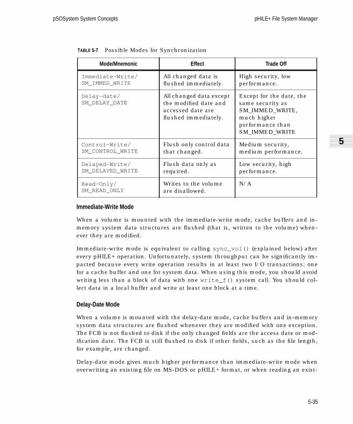
pSOSystem System Concepts pHILE+ File System Manager
5
sc.book Page 35 Friday, January 8, 1999 2:07 PM
Immediate-Write Mode
When a volume is mounted with the immediate-write mode, cache buffers and in-memory system data structures are flushed (that is, written to the volume) when-ever they are modified.
Immediate-write mode is equivalent to calling sync_vol() (explained below) afterevery pHILE+ operation. Unfortunately, system throughput can be significantly im-pacted because every write operation results in at least two I/O transactions: onefor a cache buffer and one for system data. When using this mode, you should avoidwriting less than a block of data with one write_f() system call. You should col-lect data in a local buffer and write at least one block at a time.
Delay-Date Mode
When a volume is mounted with the delay-date mode, cache buffers and in-memorysystem data structures are flushed whenever they are modified with one exception.The FCB is not flushed to disk if the only changed fields are the access date or mod-ification date. The FCB is still flushed to disk if other fields, such as the file length,for example, are changed.
Delay-date mode gives much higher performance than immediate-write mode whenoverwriting an existing file on MS-DOS or pHILE+ format, or when reading an exist-
TABLE 5-7 Possible Modes for Synchronization
Mode/Mnemonic Effect Trade Off
Immediate-Write/SM_IMMED_WRITE
All changed data isflushed immediately.
High security, lowperformance.
Delay-date/SM_DELAY_DATE
All changed data exceptthe modified date andaccessed date areflushed immediately.
Except for the date, thesame security asSM_IMMED_WRITE,much higherperformance thanSM_IMMED_WRITE
Control-Write/SM_CONTROL_WRITE
Flush only control datathat changed.
Medium security,medium performance.
Delayed-Write/SM_DELAYED_WRITE
Flush data only asrequired.
Low security, highperformance.
Read-Only/SM_READ_ONLY
Writes to the volumeare disallowed.
N/A
5-35

pHILE+ File System Manager pSOSystem System Concepts
sc.book Page 36 Friday, January 8, 1999 2:07 PM
ing file on MS-DOS format. The performance can be twice or even more since thereis no need to seek between the file's data blocks and the file's date information. Allother operations, including extending a file, behave exactly the same as immediate-write mode. In the event of a crash, the security is the same as immediate-writemode, except that the access date or modification date of existing files read or over-written, but not extended, can be lost.
Control-Write Mode
When a volume has been mounted with control-write mode, every time an in-mem-ory system data structure is modified, it is flushed to disk. For example, if the con-tents of a File Control Block is changed, it is flushed. User data, however, is notflushed immediately and may linger in a cache buffer for an indefinite period oftime.
Control-write mode provides the same level of volume integrity as immediate-writemode, but provides less protection for your data in the event of a system failure. Itsuse, however, can significantly improve throughput. The difference is most dramaticwhen the application is performing write_f() operations involving small numbersof bytes.
Delayed-Write Mode
When a volume has been mounted with delayed-write mode, the pHILE+ file systemmanager flushes memory-resident data only when required by normal operation.File Control Blocks are flushed only when a file is closed or a volume is synchro-nized. Cache buffers are flushed only when they are reused, a volume is synchro-nized, or a volume is unmounted.
The delayed-write mode is the most efficient of the four modes because it minimizesI/O. When using this mode, however, a system failure may leave a volume with in-consistent system data structures and old user data.
Delayed-write mode is a reasonable choice when high throughput is required. Nor-mally, using the sync_vol() system call periodically is sufficient to maintain aconsistent volume.
Read-Only Mode
This mode prevents writing to the volume. Only system calls that do not write to thevolume are allowed. On MS-DOS volumes, these system calls do not update the fileaccess date. All supported system calls that write to the volume abort and returnthe E_RO error. Unsupported system calls still return their usual error code.
5-36

pSOSystem System Concepts pHILE+ File System Manager
5
sc.book Page 37 Friday, January 8, 1999 2:07 PM
This synchronization mode is useful for both CD-ROM and MS-DOS FAT volumes.However, it can be used on any local volume. It is the only synchronization modesupported on CD-ROM volumes, or write protected MS-DOS volumes. If an MS-DOSFAT volume is only read, not written, read-only mode is faster than the other syn-chronization modes since it does not update the file access date or the archiveattribute.
5.6.6 sync_vol
The sync_vol() system call copies the contents of the cache buffers and all in-memory system data structures to a volume. sync_vol() is automatically executedwhen a volume is unmounted. It is not needed for a volume if the volume ismounted with immediate write mode.
5.7 pHILE+ Format Volumes
This section discusses the special system calls available only for pHILE+ format vol-umes and how pHILE+ format volumes are organized.
5.7.1 System Calls Unique to pHILE+ Format
This section discusses those services available after you create a pHILE+ format vol-ume. These services are not available with any other file system format.
annex_f
write_f() operations will automatically add new blocks to a file as required, butthe blocks added often are not contiguous. This situation can be partially controlledon pHILE+ format volumes by using a larger file expansion unit. For even more effi-cient, contiguous grouping, the annex_f() function may be used to manually allo-cate or expand a file’s physical size, in anticipation of new data.
Call annex_f() by passing the number of contiguous blocks you wish to add to afile, known by a file ID; the call will return the number of blocks added. annex_f()does nothing, however, to the logical size of the file — see the cautions in the de-scription of the call. If a file’s final size can be estimated in advance, thenannex_f() may be used to allocate a single contiguous extent for the file immedi-ately after its creation. So long as subsequent write operations do not extend pastthis size, the file will be truly contiguous. If the file must be expanded, then this maybe left implicitly to write_f() , or performed explicitly using additional annex_f()operations.
5-37

pHILE+ File System Manager pSOSystem System Concepts
sc.book Page 38 Friday, January 8, 1999 2:07 PM
lock_f
The pHILE+ file system manager allows a single file to be opened and accessed bymore than one task simultaneously. Concurrent read access is generally quite safe;however, if one or more tasks perform write operations (concurrent update), then itmay be necessary for such tasks to secure exclusive access to all or part of the file.
The lock_f() function allows a task to lock a specified region of a file. As long asthe lock is in effect, the pHILE+ file system manager will prevent all other file con-nections from reading, writing or locking that region of the file, thus providingexclusive access to a single connection.
lock_f() requires two parameters. The first is the position of the first byte to lock.The second is the number of bytes to lock. A lock may start and/or end beyond boththe physical or logical end of a file. This allows a lock to anticipate future expansionof a file. Thus, lock_f() can be used to prevent all other connections to the filefrom:
■ Modifying or appending any data in the locked region of the file, and
■ Reading any data in, or being appended to, the locked region of the file.
When a lock is in place, the locked region can be accessed only by the task thatplaced the lock and then only via the file ID with which the lock was placed.
Each connection to a file may lock only one region of a file at any time. If a taskneeds to lock two different parts of a file simultaneously, then it must open the filetwice to obtain a second connection (via a different file ID).
If a lock_f() call is issued through a connection that has an existing lock, thenthe existing lock is automatically removed and replaced by the new lock. This lockreplacement takes place as an atomic operation. That is, the existing lock is re-moved, and the new lock is set in a single operation. This precludes, in the case thatthe old and new regions overlap, any opportunity for another task to access — oreven worse, lock — the overlapped region during the replacement window.
To remove an existing lock, replace it with a new lock of length zero, using the samefile ID.
A lock prevents offending read_f() , write_f() , and lock_f() operations only. Itdoes not prevent another task from adding blocks to a file with the annex_f() call.Nor does it prevent access to the file's data via the read_vol() and write_vol()calls.
5-38

pSOSystem System Concepts pHILE+ File System Manager
5
sc.book Page 39 Friday, January 8, 1999 2:07 PM
verify_vol
verify_vol() checks and optionally corrects control structures on a pHILE+ for-matted volume. It can be used to perform the following actions:
■ Volume Integrity Verification
■ Volume Correction
■ Bad Block Elimination
pHILE+ format provides a method to automatically determine whether to runverify_vol() . A volume modified bit was added to the root block by pHILE+ 4.x.x.This bit is set the first time any block is written to the file system. It is cleared afterall modifications to the volume are successfully written to disk by sync_vol() orthe last step of unmount_vol() . This bit can be checked when a volume is firstmounted. If the bit is set, verify_vol() should be run since the volume was notproperly flushed to disk. The bit is actually a 4-byte big-endian word at offset 52 inthe root block.
Refer to verify_vol() in the pSOSystem System Calls manual for further informa-tion.
5.7.2 How pHILE+ Format Volumes Are Organized
As mentioned in Section 5.6.3 on page 5-31, a pHILE+ format volume consists of asequence of logical blocks. Several blocks per volume are dedicated to hold manage-ment information for the volume. These blocks are accessed directly by the pHILE+file system manager without going through normal file operations.
The management blocks are defined as follows:
BOOTLOAD The first and second blocks (0 and 1) are never used by thepHILE+ file system manager. They are reserved in case abootstrap loader is needed for the volume.
ROOTBLOCK Block 2 is always used as the root block for a volume. Thisblock contains all information needed by the pHILE+ filesystem manager to locate other vital information on thevolume.
ROOTDIR Block 3 is always used to hold the first block of the rootdirectory for the volume. As the root directory grows, addi-tional blocks are allocated dynamically as required.
5-39

pHILE+ File System Manager pSOSystem System Concepts
sc.book Page 40 Friday, January 8, 1999 2:07 PM
Thus, a volume has five initial data structures containing vital internal managementdata. Before a volume can be used, it must be initialized using the init_vol() call,described in pSOSystem System Calls. init_vol() builds the root block, the rootdirectory, the bitmap, and the FLIST structures on the volume.
The bitmap can be placed anywhere on a volume and it is always followed by theFLIST. They need not be contiguous with the root block, root directory or any otherdata structure on the volume. Because the bitmap is used during write operations,and FLIST is used extensively during all file creation and connection, overall volumeaccess can be improved by careful placement of these structures.
The Root Block
The root block is the starting point from which the pHILE+ file system managerlocates all other data on the volume. For this purpose, it contains the:
In addition, the root block contains the following information about the volume:
BITMAP This contiguous sequence of blocks is used to hold thebitmap for the volume, which uses bits to indicate whatblocks are free. Its size and location are determined byparameters that you supply when you initialize thevolume.
FLIST This contiguous sequence of blocks is used to hold the filedescriptors for the volume. It is positioned immediatelyfollowing the bitmap. Its size is determined by parametersyou supply when you initialize a volume.
BITMAP_ADDRESS The starting block number of the volume bitmap
FLIST_ADDRESS The starting block number of FLIST
DATA_ADDRESS The starting block number of data space (See Control andData Block Regions on page 5-42.)
INIT_TIME The time and date of volume initialization
VOLUME_NAME The volume label
VOLUME_SIZE The volume size in blocks
NUMBEROF_FD The number of file descriptors (that is, the FLIST size)
VALIDATE_KEY Volume initialization successful
5-40

pSOSystem System Concepts pHILE+ File System Manager
5
sc.book Page 41 Friday, January 8, 1999 2:07 PM
The Root Directory
The volume’s root directory is a directory file that forms the starting point fromwhich the pHILE+ file system manager locates all other files on a volume. From theroot directory emanates the tree structure of (sub)directories and ordinary files. Inthe simplest case, the root directory contains only ordinary files, thus yielding aone-level directory structure common in less-sophisticated file systems.
Immediately after a volume has been initialized, its root directory contains two files:FLIST.SYS , which is the volume’s list of file descriptors, and BITMAP.SYS, which isthe volume’s map of occupied blocks.
As with any user file, ordinary or directory, the root directory is expanded automati-cally by the pHILE+ file system manager, as required. For directory files, suchexpansion occurs one block at a time, and the blocks are generally not contiguous.Contiguous expansion of directory files can be achieved using the annex_f()system call described in pSOSystem System Calls.
The Volume Bitmap
A volume’s bitmap is actually a system file. It is read-only; it performs the criticalfunction of tracking the usage of each block on the volume. One bit is used to tageach block in the volume. If a block is allocated to a file, then the corresponding bitis set to 1. If a block is free, the corresponding bit is 0.
The size of the bitmap is determined by the size of the volume. Thus, for example, ifthe volume has 32K blocks, then the bitmap uses 32K bits or 4 Kbytes. If block sizeis 1 Kbyte, then 4 blocks are allocated for this bitmap. Immediately after a volumehas been initialized, its bitmap shows blocks used by the bootloader, the root block,the bitmap itself, and FLIST.SYS .
The bitmap can be read as <volume>/BITMAP.SYS . This file is write-protected, andhence cannot be written to directly or deleted.
The File Descriptor List
Every file, whether it is an ordinary or directory file, requires a control structurecalled a file descriptor (FD). Each volume contains its own list of file descriptors,called the FLIST, which is stored in a contiguous sequence of blocks. More detailsabout file descriptors are in The File Descriptor on page 5-43.
You specify the number of file descriptors in the FLIST when you initialize a volume.Each file descriptor is 128 bytes long. Therefore, if the number of file descriptors
5-41

pHILE+ File System Manager pSOSystem System Concepts
sc.book Page 42 Friday, January 8, 1999 2:07 PM
specified is 100, the FLIST occupies 12800 bytes, or 13 blocks if the block size is1 Kbyte.
Note that if the number of file descriptors on a volume is specified as n, then themaximum number of user-created files that can exist on the volume is n. The num-ber of file descriptors created will actually be (n + 4), because four internal systemfiles are always present: the root directory (/ ), /BITMAP.SYS , /FLIST.SYS , and areserved null file. These system files are write-protected, and cannot be written todirectly or deleted.
Control and Data Block Regions
pHILE+ format volumes recognize two types of file blocks: control blocks and datablocks. Control blocks contain pHILE+ data structures such as:
■ The bootload (blocks 0 and 1)
■ The root block (block 2)
■ The bitmap
■ The FLIST
■ All directory file blocks
■ Indirect and index blocks
Indirect and index blocks are used with extent maps and are explained in TheExtent Map on page 5-45.
Data and control blocks can be either intermixed or partitioned. Partitioning controland data blocks is a unique feature of pHILE+ format volumes and makes thepHILE+ file system manager capable of working with write-once devices. When apartition is used, the logical address space of a volume is divided into two regions:one for control blocks and one for data blocks. Using this method, control blockscan be temporarily maintained on an erasable media while data blocks are writtenon a write-once device. After the data partition of a volume is filled, the informationfrom the control blocks that had been on erasable media can be transferred to thewrite-once device, where it is permanently recorded.
Intermixing control and data blocks means that your data and pHILE+ data struc-tures will be written randomly on a device.
The manner in which control and data blocks are organized on a volume is deter-mined when the volume is initialized. One of the input parameters to init_vol()specifies the starting block number of the volume’s data blocks. If 0 is specified,
5-42

pSOSystem System Concepts pHILE+ File System Manager
5
sc.book Page 43 Friday, January 8, 1999 2:07 PM
then the data and control blocks are intermixed. Otherwise, data blocks begin at thespecified block. The starting data block number must be divisible by eight. Forexample, if a data block starting number of 200 is specified on a volume containing5000 blocks, then blocks 2 - 199 (recall blocks 0 and 1 are not used by the pHILE+file system manager) are control blocks and blocks 200 - 4999 are data blocks.
5.7.3 How Files Are Organized
A file is a collection of blocks that contain data, a file descriptor that contains con-trol information, and an entry in a parent directory file.
The following sections outline how files are constructed and how data in them isused.
The File Number
Externally, a file is specified by its pathname. Internally, the pHILE+ file systemmanager converts this pathname into a corresponding file number, which is in-dexed. With this file number, the pHILE+ file system manager accesses a filedescriptor, and uses its content to perform the necessary operations on the file. Younormally do not use the file number externally as a file ID. A call such ascreate_f() , for example, returns an external file ID, not the internal, proprietaryfile number. However, file numbers are used in the get_fn() , read_dir() ,open_fn() , and stat_f() system calls.
The File Descriptor
Each file descriptor is 128 bytes and contains the following information:
■ The logical file size in bytes
■ The physical file size in blocks
■ The file type: directory or ordinary, system or data
■ The time of last modification
■ The file’s expansion unit
■ The file’s extent map.
5-43

pHILE+ File System Manager pSOSystem System Concepts
sc.book Page 44 Friday, January 8, 1999 2:07 PM
File Types
There are two type attributes associated with a file. A file may be an ordinary or adirectory file, and it may be a system file or a data file. Ordinary and directory fileswere discussed above.
System files are created by the pHILE+ file system manager when a volume is initial-ized. There are three system files per volume:
Because system files contain vital data structures, they are protected against userremoval and modification. Reading, however, is allowed.
Time of Last Modification
The pHILE+ file system manager maintains the time at which a file was last modi-fied. This field is initialized when a file is created; thereafter, it is updated whenevera file is written, or when blocks are annexed to the file.
The File Expansion Unit
If a write_f() operation extends past the current physical size of a file, the pHILE+file system manager will automatically expand the file to hold the new data. Thistype of file expansion is governed by the following considerations.
When a file is created, you supply a parameter called an expansion unit that deter-mines the minimum expansion increment to use during write_f() operations.This parameter specifies the minimum number of physically contiguous blocks thepHILE+ file system manager attempts to allocate when additional space is requiredby file. This is a lower-bound number, because the number of blocks allocated isactually determined by either the expansion unit, or the number of blocks needed tosatisfy the current write_f() operation, whichever is greater.
Extents
A file is treated simply as a sequence of logical blocks. Each such block correspondsto a physical block on the volume. Because the physical blocks that comprise a filemay be scattered throughout a volume, the pHILE+ file system manager implementsa structure called an extent to keep track of a file’s blocks, and hence its data.
/BITMAP.SYS The volume’s bitmap
/FLIST.SYS The volume’s FLIST
/ The volume’s root directory
5-44

pSOSystem System Concepts pHILE+ File System Manager
5
sc.book Page 45 Friday, January 8, 1999 2:07 PM
An extent is a sequence of physically contiguous blocks. An extent consists of one ormore blocks; similarly, a file with data consists of one or more extents.
A file can acquire an extent in one of two ways:
■ During a write_f() operation, when a file is expanded; or
■ During an annex_f() operation
These operations also might not produce a new extent, because the pHILE+ file sys-tem manager may merge the newly allocated blocks into an existing extent (logicallythe last extent) if the new blocks are contiguous with that extent.
An extent is described by an extent descriptor:
< starting block number, number of blocks >
which identifies the physical address of the blocks that make up the extent.
The Extent Map
The extent map for a file is a list of its extent descriptors. For reasons of efficiency,this map is organized by layers of indirection.
The first 10 extent descriptors are located in the file’s file descriptor. Additionalextent descriptors, when needed, are stored in indirect blocks. Each indirect blockis a physical block that contains up to n extent descriptors. Because an extent de-scriptor is 8 bytes, the number n of extent descriptors that can be held in an indi-rect block is (blocksize / 8). For example, if blocksize is 1 Kbyte, then n is 128.Indirect blocks are allocated as needed for each file.
Each indirect block is addressed via an indirect block descriptor which is also a pairof words:
< starting block number, last logical block number + 1 >
where the first item is a physical block number, and the second item is the logicalnumber (+ 1) of the last block contained in this indirect block of extent descriptors.This last number is useful for quickly determining whether an indirect block needsto be searched while locating a particular logical block within a file.
The indirect block descriptor for the first indirect block, if needed, is held in a filedescriptor. If more than one indirect block is needed, as in the case of rather largeand scattered files, then the second through (n + 1)th indirect block descriptors areheld in an index block.
5-45

pHILE+ File System Manager pSOSystem System Concepts
sc.book Page 46 Friday, January 8, 1999 2:07 PM
If allocated, this index block will contain up to n indirect block descriptors. Again,because each indirect block descriptor is 8 bytes long, the number n of indirectblock descriptors in the index block is equal to (blocksize / 8). For example, if block-size is 1 Kbyte, then this number will be 128. The physical block address of theindex block is contained in a file descriptor. A file can have only one index block.
The structure of the extent map ensures that, in the worst case, no more than twoblock accesses are needed to locate an extent descriptor. Moreover, the cache buff-ers will tend to retain frequently used index and indirect blocks.
This extent map structure clearly favors file contiguity. For example, if a file can becovered in fewer than 10 extents, then access to any of its data can be accomplishedvia the file descriptor alone.
The extent map will hold up to [n * (n + 1) + 10] extents, where n is (blocksize / 8), asabove. For example, if blocksize is 1 Kbyte, then the maximum number of extentsper file is [(128 * 129) + 10], or 16522. In the worst case of 1 block per extent, a filecan contain 16522 blocks, or 16 megabytes of data. However, because the pHILE+file system manager contains both implicit and explicit features to “cluster” manyblocks into a single extent, the number of extents required to map a file is usuallyvery much smaller. In fact, even for a very large file, the number of extents needed tomap the file rarely exceeds 100.
Figure 5-4 on page 5-47 illustrates an example of an extent map layout.
5-46

pSOSystem System Concepts pHILE+ File System Manager
5
sc.book Page 47 Friday, January 8, 1999 2:07 PM
Index
Indirect 0
Size
Extent 9
Size
Extent 0
File Descriptor
Indirect 1
Last block +1
Indirect n
Last block +1
Index Block
Extent 10
Size
Extent n + 9
Size
Indirect Block #0
Size
Size
Indirect Block #1
Size
Size
Indirect Block #n
Extent n + 10
Extent 2n + 9
Extent n*n + 10
Extent (n+1)n + 9
FIGURE 5-4 The Layout of an Extent Map
5-47

pHILE+ File System Manager pSOSystem System Concepts
sc.book Page 48 Friday, January 8, 1999 2:07 PM
5.7.4 Data Address Mapping
The pHILE+ file system manager allows you to access file content down to individualbytes. For each file access, the pHILE+ file system manager performs a number ofaddress translations that convert or map your stretch of data into a volume block orblocks.
As an example of file content access, consider a file with three extents. Assume itsfile descriptor’s extent map looks like the following:
(060,5)
(789,2)
(556,1)
That is, the file has 8 blocks. Assume that block size is 1 Kbyte. If a read call re-quests 100 bytes, starting at byte number 7000, the request is processed by thepHILE+ file system manager as follows:
1. Byte 7000 divided by 1024 = 6, remainder = 856.
2. Logical file block 6 is needed, because blocks are numbered from 0.
3. According to extent map, block #6 is the 2nd block in the extent (789,2).
4. The pHILE+ file system manager calls your driver to read volume block #790.
5. The pHILE+ file system manager extracts bytes 856 to 955 from the 1024 bytesthat were read in.
5.7.5 Block Allocation Methods
Because blocks are the basic unit of the pHILE+ volume, block allocation algorithmsare extremely important to system throughput. Blocks must be allocated whenever:
■ A write_f() extends the logical size of a file beyond the file's physicalsize.
■ An annex_f() call is made.
■ A new block must be added to a directory to accommodate a new entry. This canhappen on a create_f() , make_dir() , or move_f() call.
■ An indirect or index block must be added when a new extent is added to a file.This can happen whenever blocks are allocated — for whatever reason.
5-48

pSOSystem System Concepts pHILE+ File System Manager
5
sc.book Page 49 Friday, January 8, 1999 2:07 PM
When more blocks are needed, the pHILE+ file system manager first determines theallocation size. This is the ideal size of the extent to be allocated. The allocation sizefor each case above is determined as follows:
Case 1: write_f( ) Extends a File
When extending an ordinary file to write data from a write_f() call, the allocationsize is the larger of the number of blocks needed for the data and the expansion unitthat you specified when the file was created. For example, assume that awrite_f() call requires two blocks. If the file was created with an expansion unit offive blocks, then the allocation size will be five blocks. On the other hand, if the file’sexpansion unit is one, then the allocation size will be two blocks.
Case 2: annex_f( ) Extends a File
The allocation size is a parameter of the annex_f() call and is thus provided by thecalling task.
Case 3: A New Entry Extends A Directory File
Directories have the following properties:
■ They grow one entry at a time;
■ Each entry is 16 bytes long; and,
■ There is no expansion unit associated with a directory
For all of these reasons, the directory allocation size is always one block.
Case 4: An Indirect or Index Block Is Needed
These are always single blocks, so the allocation size is one block. Indirect and in-dex blocks are explained below.
After selecting the allocation size, the pHILE+ file system manager chooses the blocktype. Ordinary files use data blocks, while pHILE+ data structures use control anddata blocks.
The block type is used to decide where in the volume to search for free space. If thevolume was partitioned into data and control regions during initialization, which isexplained in more detail below, only the relevant portion of the volume will be used.
The search does not always start with the first block in the appropriate region.Rather, the pHILE+ file system manager will start searching in the bitmap of the
5-49

pHILE+ File System Manager pSOSystem System Concepts
sc.book Page 50 Friday, January 8, 1999 2:07 PM
block last referenced. This increases the chance of scanning a block in the cache,and thus enhances throughput.
The search involves locating the first unused extent containing at least the requirednumber of blocks. This search can have three outcomes:
1. A sufficiently large extent is found and allocated, in which case thesearch is successfully completed. If the length of the extent is greater than theallocation size, the extent will be split.
2. No extents equal to or greater than the allocation size are found. In this case,the pHILE+ file system manager will allocate the largest remaining extent in theappropriate region. If the calling function is annex_f() , the number of blocksactually allocated is returned to the caller. If a write_f() is executed, a newallocation size is calculated (depending on the number of blocks not yet allo-cated) and the operation is repeated. That way, one write_f() call can addseveral extents to a file.
3. The volume is full (no free blocks). In this case, a “volume full” error is returnedto the calling task.
The time to read and write to a file depends on how fragmented the file is. A file frag-mented into many small and scattered extents will take more time to access than afile consisting of fewer and larger extents. If a file can be compacted into 10 or fewerextents, then all of the file’s data blocks can be identified using an extent mapstored in the File Control Block. This is the optimal case. If a file has more than 10extents, indirect blocks or index blocks must be used, which reduces access times.
Some attention should be given to a file’s expansion unit specification, which isdescribed in The File Expansion Unit on page 5-44. A larger expansion unit resultsin higher throughput, but may waste disk space, because some blocks may not beused. On the other hand, a smaller expansion unit uses disk space more efficiently,but may cause fragmentation. This fragmentation will be a function of:
■ The average number of bytes written per write_f() ;
■ The number of annex_f() calls used; and,
■ Concurrent file activity; that is, how many tasks are using the volume at thesame time.
When the pHILE+ file system manager needs to add blocks to a file, it always checksto see if the new blocks can be merged into the last extent used.
5-50

pSOSystem System Concepts pHILE+ File System Manager
5
sc.book Page 51 Friday, January 8, 1999 2:07 PM
5.7.6 How Directories Are Organized
Directories implement the hierarchical file structure of the pHILE+ file system man-ager. A volume’s directory tree structure is built on top of, but also out of, the basicdata file structure. That is, directory files are treated in almost all respects as ordi-nary data files. Directory files hold data about their children, and the parent of a di-rectory will hold data about the directory. A directory file contains an array ofentries. Each entry describes a file in the directory. An entry is nothing more than a2-tuple, as follows:
Entry: < filenumber, filename >.
filenumber is the number of the file and filename is its name. Each directory entryuses 16 bytes, so if the block size is 1 Kbyte, one block can store 64 entries.
When a file is created, the pHILE+ file system manager assigns it a file descriptor inthe volume’s FLIST, described below, and makes an entry in the directory file towhich it belongs.
5.7.7 Logical and Physical File Sizes
Files occupy an integral number of storage blocks on the device. However, thepHILE+ file system manager keeps track of the length of a file in bytes. Unless thelength of a file is an exact multiple of the block size, the last block of the file will bepartially used. There are therefore two sizes associated with every file: a logical sizeand a physical size.
The logical size of a file is the number of data bytes within the file that you can ac-cess. This size automatically increases whenever data is appended to the file, butnever decreases.
The physical size of a file corresponds to the number of blocks currently allocated tothe file. Thus the logical and physical sizes of a file are generally different, unless afile's logical size happens to exactly fill the number of physical blocks allocated tothe file. As with its logical size, a file's physical size never decreases, except when itis deleted or truncated to less than the physical size.
5-51

pHILE+ File System Manager pSOSystem System Concepts
sc.book Page 52 Friday, January 8, 1999 2:07 PM
5.8 Error Handling and Reliability
pHILE+ handles errors differently for each of five classes of errors. Fatal errors,pHILE+ code check sum wrong, for example, are detected during pHILE+ initializa-tion. They abort initialization of pHILE+. All other error classes normally cause thecurrent pHILE+ system call to abort and return an error code. NFS and RPC errorsare errors returned by NFS and RPC system calls made by pHILE+ NFS client.Before being returned they are translated to pHILE+ error codes as shown in tablesB-5 and B-6, respectively, in the pSOSystem System Calls manual. Disk drivererrors are errors returned by disk drivers called from pHILE+. They are returned as-is. Finally, nonfatal pHILE+ errors are errors detected within pHILE+ system calls.They have their own pHILE+ error codes.
NFS timeouts, i.e. error E_ETIMEDOUT, are automatically retried by the network andRPC code. pHILE+ 4.x.x added two fields to nfsmount_vol() parameternfs_parms to control this. Retries is the number of retries. This does not includethe initial try. Zero means try one time with zero retries. timeo is the timeout inter-val in tenths of a second. For backwards compatibility, if timeo is zero, it ischanged to 30, or 3 seconds, and retries is changed to 2, for try 3 times. These arethe parameters used by earlier versions of pHILE+ that did not allow specifyingthese parameters.
Disk driver errors can be retried by providing an optional disk driver error calloutroutine. pHILE+ configuration table entry fc_errco points to the disk driver errorcallout routine, or is zero if one is not provided. If the callout routine exists, it iscalled after every disk driver error. It is passed the BUFFER_HEADERthat was passedto the disk driver, the error code returned by the driver, and the direction of thetransfer, namely, read or write. If it returns a nonzero value, the pHILE+ system callis aborted and that value is returned as the error code. The callout routine canreturn the original error code or a new value if it wants to change the error code. If itreturns zero, the read or write is retried. The callout routine should not blindlyreturn 0 all the time. This would cause an infinite loop if a repeatable disk drivererror occurs. Note that the system call in progress during a disk driver error doesnot have any relationship to the system call to which the disk write belongs if thedisk write was done to flush a modified cache buffer to disk. The disk driver errormight even be on a different volume since cache buffers from any volume can bechosen to be flushed if all cache buffers are in use and one is needed.
5-52

pSOSystem System Concepts pHILE+ File System Manager
5
sc.book Page 53 Friday, January 8, 1999 2:07 PM
pHILE+ is designed for reliability despite system crashes whether caused by powerfailure or anything else. There are two issues to consider for a system crash and aredescribed in the following subsections. The issues are:
■ What happens to pHILE+ system calls that completed before the crash?
■ What happens to a pHILE+ system call in progress at the time of the crash?
What happens to pHILE+ system calls that completed before the crash?
If something is cached in memory and not written to disk, it will be lost. pHILE+ hassynch_modes to adjust what could be cached in memory and not written to disk.They trade off performance for reliability of completed pHILE+ system calls. IfSM_IMMED_WRITEis used, nothing is lost from any completed pHILE+ system callsince all data and control information are written to disk before a pHILE+ systemcall completes. If SM_DELAY_DATEis used, the only thing that can be lost is file anddirectory date and times since all data and all control information except that arewritten to disk before a pHILE+ system call completes. If SM_CONTROL_WRITEisused, data could be lost, but file system control information is not lost, since controlinformation, but not data, is written to disk before a pHILE+ system call completes.If SM_DELAYED_WRITEis used, both data and file control system information couldbe lost since neither is written to disk before a pHILE+ system call completes. There-fore disk consistency is maintained by all except SM_DELAY_WRITE, since file sys-tem control information is written to disk immediately. Data consistency ismaintained by only SM_IMMED_WRITEand SM_DELAY_DATEsince only they writedata to disk immediately. See Section 5.6.5 on page 5-34.
What happens to a pHILE+ system call in progress at the time of the crash?
What happens if the system crashes during a disk write is a function of the diskhardware, not of pHILE+ or even the disk driver. What happens if the systemcrashes between disk writes is the concern of pHILE+. pHILE+ orders disk writes tominimize disk corruption if the system crashes between disk writes of a pHILE+ op-eration that requires multiple disk writes. pHILE+ version 4.x.x improved this order-ing to minimize disk corruption in more pHILE+ operations than earlier versions ofpHILE+.
Table 5-8 on page 5-54 shows the disk corruption that could occur if the systemcrashed between multiple writes of a pHILE+ operation. If the disk cannot be cor-rupted OK is listed. Otherwise, the potential errors are listed. Further operationsafter the potential error occurs could cause other errors. An entry is marked(Improved) if it has been improved in pHILE+ 4.x.x. This table applies to allsynch_modes except SM_DELAYED_WRITE. When using SM_DELAYED_WRITE, all
5-53

pHILE+ File System Manager pSOSystem System Concepts
sc.book Page 54 Friday, January 8, 1999 2:07 PM
disk writes can occur in any order, so any error could occur after a crash. Whenusing SM_CONTROL_WRITE, data disk writes can occur in any order, but controldisk writes are in the order of the table. Thus, the table applies toSM_CONTROL_WRITE, but the data might not actually be there.
Preventing the error in move file/directory is not desirable. It is better to have acrash at the wrong time during a move_f() operation leave two directory entries forthe same file which causes the errors below, than no directory entries which woulddelete the file.
.
Another issue is bad block handling. Bad block handling can be handled at manydifferent levels from disk on up. Blocks can be bad when a disk is initialized, or gobad later. Two techniques used for bad block handling are to mark them bad or in-use so they are never used or not used again, and block forwarding where a goodblock is substituted for a bad block.
The technique used for bad block handling depends on when the block went bad.Blocks that are bad when a disk is initialized can be handled by either markingblocks bad or block forwarding. Blocks that go bad later and are found to be bad
TABLE 5-8 Errors caused by a crash between disk writes of a pHILE+ operation
Operation pHILE+ format MS-DOS FAT format
Create file OK (Improved) OK
Make directory OK (Improved) OK
Remove file/directory OK (Improved) OK (Improved)
Move file/directory VF_FDMU† (Improved)
†. VF_FDMU - FD in use by more than one file.
(Improved‡)
‡. Two directory entries refer to the same cluster. This is a special case of cross-linked files.
Annex OK N/A
Write: Increase file size OK OK
Truncate: Increase file size OK OK
Truncate: Decrease file size OK OK
Read OK OK
Write: Logical size < physical OK OK
5-54

pSOSystem System Concepts pHILE+ File System Manager
5
sc.book Page 55 Friday, January 8, 1999 2:07 PM
when accessed cannot be handled by marking blocks bad. For a write, but not aread, they can be handled by bad block forwarding.
The technique used for bad block handling depends on the level at which the badblock is handled. Marking blocks bad and not allocating them is normally done bythe file system. On pHILE+ format, the verify_vol() system call can be used forthis. Bad block forwarding is normally done by the disk itself, or by the disk driver.For example, SCSI hard disks usually provide bad block forwarding. The disk istested at the factory for bad blocks when it is physically formatted. Any bad blocksare replaced by forwarding them to other extra blocks reserved to replace badblocks. In addition, there are SCSI commands to forward additional bad blocks afterdisk initialization. pSOSystem disk drivers do not use these SCSI commands.
Finally, for pHILE+ format, but not MS-DOS FAT format, pHILE+ provides a way toverify disk consistency, and repair a corrupted disk. See the verify_vol() systemcall in the System Calls Reference manual, and System Concepts Section 5.7 onpage 5-37 and all subsections except Section 5.6 on page 5-30.
5.9 Loadable Device Drivers
pHILE+ provides support for implementing a reference count to prevent loadabledisk device drivers from being unloaded when they are in use by pHILE+. pHILE+calls ioj_lock() before using a driver, for example, at the beginning of any localvolume initialization or mount. It calls ioj_unlock() at the end of any local vol-ume initialization or unmount, and if a local volume mount or initialization fails.
5.10 Special Considerations
5.10.1 Restarting and Deleting Tasks That Use the pHILE+ File System Manager
During normal operation, the pHILE+ file system manager internally allocates andholds resources on behalf of calling tasks. Some resources are held only during exe-cution of a service call, while others are held indefinitely based on the state of thetask (for example when files are open). The pSOS+ service calls t_restart() andt_delete() asynchronously alter the execution path of a task and present specialproblems relative to management of these resources.
This section discusses delete-related and restart-related issues in detail and pre-sents recommended ways to perform these operations.
5-55

pHILE+ File System Manager pSOSystem System Concepts
sc.book Page 56 Friday, January 8, 1999 2:07 PM
Restarting Tasks That Use the pHILE+ File System Manager
The pSOS+ kernel allows a task to be restarted regardless of its current state. Therestart operation has no effect on currently opened files. All files remain open andtheir L_ptr’s are unchanged.
It is possible to restart a task while the task is executing code within the pHILE+component. Consider the following example:
1. Task A makes a pHILE+ call.
2. While executing pHILE+ code, task A is preempted by task B.
3. Task B then restarts task A.
In such situations, the pHILE+ file system manager correctly returns resources asrequired. However, a pHILE+ or MS-DOS file system volume may be left in an incon-sistent state. For example, if t_restart() interrupts a create_f() operation, afile descriptor (FD) may have been allocated but not the directory entry. As a result,an FD may be permanently lost. t_restart() detects potential corruption and re-turns the warning code 0x0D. When this warning code is received, verify_vol()should be used on all pHILE+ format volumes to detect and correct any resultingvolume inconsistencies.
Deleting Tasks That Use the pHILE+ File System Manager
The following normally does not apply for pSOSystem 2.5 and pSOS+ 2.5 and laterversions. The issues are the same but automatically satisfied. The pSOS+ kerneldoes a callout before task deletion that performs the task delete code given below.Thus, when the t_delete() is actually done, no resources are held, and error code0x18 will not be returned.
To avoid permanent loss of pHILE+ resources, the pSOS+ kernel does not allowdeletion of a task that is holding any pHILE+ resource. Instead, t_delete()returns error code 0x18, which indicates that the task to be deleted holds pHILE+resources.
The exact conditions under which the pHILE+ file system manager holds resourcesare complex. In general, any task that has made a pHILE+ service call may holdpHILE+ resources. close_f(0) , which returns all pHILE+ resources held by thecalling task, should be used prior to calling t_delete() .
The pNA+ and pREPC+ components also hold resources which must be returnedbefore a task can be deleted. These resources are returned by calling close(0) andfclose(0) , respectively. Because the pREPC+ component calls the pHILE+ file
5-56

pSOSystem System Concepts pHILE+ File System Manager
5
sc.book Page 57 Friday, January 8, 1999 2:07 PM
system manager, and the pHILE+ file system manager calls the pNA+ component (ifNFS is in use), these services must be called in the correct order.
Example 5-1 shows a sample code fragment that a task can use to delete itself.
EXAMPLE 5-1: Sample Code a Task Can Use to Delete Itself
#if SC_PLM == YESsl_release(-1); /* release pLM+ shared libraries */#endif
#if SC_PREPC == YESfclose(0); /* return pREPC+ resources */#endif
#if SC_PHILE == YESclose_f(0); /* return pHILE+ resources */#endif
#if SC_PNA == YESclose(0); /* return pNA+ resources */#endif
#if SC_PSE == YESpse_close(0); /* return pSE resources */#endif
#if SC_PREPC == YESfree(-1); /* return pREPC+ memory */#endif
t_delete(0); /* and commit suicide */
The conditionals prevent calls to components that are not included. You can omitthe conditionals if you also omit the calls to components that are not included ornot in use.
Because only the task to be deleted can make the necessary close calls, the simplestway to delete a task is to restart the task and pass arguments requesting self dele-tion. Of course, the task being deleted must contain code to handle this condition.
5-57

pHILE+ File System Manager pSOSystem System Concepts
sc.book Page 58 Friday, January 8, 1999 2:07 PM
5-58
sc.book Page 1 Friday, January 8, 1999 2:07 PM
6
pLM+ Shared Library Manager6
This chapter describes pLM+, the Shared Library Manager option for pSOSystem,that manages the use of shared libraries for pSOS+. The following topics arediscussed:■ Overview of Shared Libraries
■ Using pLM+
■ Writing Shared Libraries
Further information regarding the pLM+ API can be found in the pSOSystem SystemCalls manual and the pSOSystem Programmer’s Reference manual.
6.1 Overview of Shared Libraries
This section covers the following topics:
■ What is a shared library?
■ In what situations are shared libraries used?
■ pLM+ features
■ Shared library architecture
6.1.1 What is a Shared Library?
A shared library is a library that can be called from other images or its own image.An image is code and/or data that is linked together. Since a shared library can becalled from other images, one copy of the shared library can be shared by severalapplications (or tasks) that are not linked to the shared library. This saves memory
6-1

pLM+ Shared Library Manager pSOSystem System Concepts
sc.book Page 2 Friday, January 8, 1999 2:07 PM
since only one copy is required. In addition, it simplifies updating a shared librarysince the applications that use it do not need to be relinked.
The shared library can be part of the pSOSystem image, part of a loadable applica-tion, or loaded by itself apart from any application. If loaded by itself, the operatingsystem manages loading and unloading. Shared libraries can be manually pre-loaded by an application, or loaded automatically the first time the first applicationcalls them. When a shared library is loaded, all the shared libraries that it useseither directly or indirectly can be automatically loaded. Shared libraries can bemanually unloaded, or unloaded automatically when the last application finishesusing them. In order to be managed by the operating system, a shared library has aname and version.
In contrast, conventional libraries can be called only from their own image, notother images. They must be linked to their caller. They cannot be loaded apart froman application. If multiple loadable applications use the same conventional libraryand are loaded, then multiple copies of the library are required. If a conventionallibrary is updated, all the applications that call it must be relinked. A conventionallibrary does not have a name or version, only a file name, and that only at link time,not at execution time.
6.1.2 In What Situations are Shared Libraries Used?
Shared libraries are used in dynamic, configurable, or upgradable environments inwhich hardware and/or software changes. The benefits of shared libraries are listedbelow along with case studies of products that could benefit from shared libraries.
■ Configurable hardware
A network router supports several types and combinations of network inter-faces. It consists of a chassis with several slots for network interface cards ofvarious types. A network interface card has a ROM that holds a loadable sharedlibrary to control the card. The shared library is on the card, so the router cansupport new network interface card types developed after the router itself.
■ Safe online hot software upgrade
When a new higher modem speed is first introduced, manufacturers do not waitfor standard protocol. Different manufacturers use different incompatible proto-cols for the new speed. Later, these protocols are replaced by a new standardprotocol. Therefore, a new modem is designed to upgrade to the standard proto-col when it becomes available. (This gives the manufacturer and the customerthe advantage of the standard protocol without having to wait for it.) Themodem calls the manufacturer, downloads the standard protocol, and replaces
6-2

pSOSystem System Concepts pLM+ Shared Library Manager
6
sc.book Page 3 Friday, January 8, 1999 2:07 PM
its own with the standard one. The replacement is done atomically after thedownload completes, so the modem is not broken if the download fails part waythrough. To save money, the modem software is stored in a large ROM. Thedownloaded protocol is stored in a small previously empty flash memory. Theportion of the modem software that implements the original protocol is a sharedlibrary. The standard protocol is a newer version of this shared library. After thenew shared library is successfully downloaded, the registered shared library isupdated with the new version. In future resets, the new shared library is regis-tered instead of the old one. The rest of the modem software, even though it is inROM and has not been changed, now uses the new standardized protocol.
■ Save memory, reduce load time, update a shared library without relinking appli-cations, and reduce application startup time.
A set-top box both displays TV and runs downloaded interactive applications.The built-in software includes shared libraries used by many of the applica-tions; for example, a library to display windows on the TV. Some of these appli-cations share functionality. Both the applications themselves, and the sharedfunctionality, are implemented as shared libraries. When an application isloaded, the shared libraries that it needs, which are not already loaded, areautomatically loaded. When an application is unloaded, the shared librariesthat it uses are automatically unloaded only if they are not used by other appli-cations as well. The use of shared libraries saves memory and reduces loadtime. The downloaded shared libraries need only be downloaded once no matterhow many applications use them, and the built-in shared libraries need not bedownloaded at all.
If the shared functionality is updated, the applications that call it do not need tobe relinked. Some of these applications are large. They are divided into pieces toreduce startup time. Only the main piece needs to be downloaded to start theapplication. The other pieces are downloaded either in the background, or thefirst time they are called, never if not called. Each of the pieces are implementedas a shared library,
There are two main architectures in using shared libraries. A system may combineboth. They are a shared library within the pSOSystem image that is called by loadedapplications, or a loaded shared library that is called by loaded applications and/orthe pSOSystem image.
6.1.3 pLM+ Features
In addition to its standard shared library management functions, pLM+ forpSOSystem also provides the following features:
6-3

pLM+ Shared Library Manager pSOSystem System Concepts
sc.book Page 4 Friday, January 8, 1999 2:07 PM
Automatic loading and unloading — If a shared library is required by your application andis not yet loaded into memory, pLM+ provides a service to automatically load theshared library into memory. Also, pLM+ can subsequently unload the sharedlibrary automatically when it is no longer needed.
Automatic handling of dependencies — If a shared library is dependent on code from othershared libraries, pLM+ automatically loads into memory all dependent libraries.
Loader independence — Applications and shared libraries may be loaded and unloadedby any means (not necessarily by the pSOSystem loader), and at any time.
Version management — pLM+ provides version checking of varying scopes that includes:exact, compatible, or any version level (see Version Handling on page 6-13).
6.1.4 Shared Library Architecture
The shared library architecture consists of the shared library host resident toolshlib , and the target resident shared library manager pLM+. Together, these pro-vide execution time binding of function calls to shared libraries. This binding can becross images; that is, a caller does not have to be linked to a shared library to call it.
pLM+ is a name server for shared libraries. It provides two classes of services: look-ing up shared libraries, and looking up symbols within shared libraries. Togetherthese two services provide execution time binding. Names are added to these twoclasses of services at different times. A shared library is added at execution time inorder to be looked up. A symbol is exported from a shared library at compile timewhen the shared library is built.
pLM+ is a pSOSystem component, not a library. Like all pSOSystem components, itcan be called from any image, not just the pSOSystem image. Since pLM+ servicesare available to any image, shared libraries can be called from any image; that is,the pSOSystem image or any loaded image.
shlib provides code stubs used by code that calls shared libraries, and data usedby pLM+. shlib is a special macro processor that reads a shared library definitionfile, and a template file. It generates a dispatch file, and a stub file. Section 6.3 onpage 6-16 provides more information about shlib .
A shared library definition file is written for each shared library. It specifies theshared library's name and version, the exported functions, and the shared librarieswhich are used by this shared library.
A template file is written for each tool chain. The template file provides the macrodefinitions used by shlib to generate the two output files. You should not need to
6-4

pSOSystem System Concepts pLM+ Shared Library Manager
6
sc.book Page 5 Friday, January 8, 1999 2:07 PM
write template files, because Integrated Systems, Inc. supplies template files forevery tool chain that we support.
The dispatch file generated by shlib is what converts a library into a sharedlibrary. It is assembled and linked with the shared library. It is not executable. Itcontains a constant data structure that supplies the information needed by pLM+ tomanage the shared library.
There are two methods to call exported shared library functions: via stubs in thestub file generated by shlib , or via function pointers obtained with pLM+ systemcalls. These two methods trade off convenience for efficiency. Calling via stubs ismore convenient since it does not require any source code changes in the callingprogram. On the other hand, calling via function pointers obtained with pLM+ sys-tem calls does require source code changes in the caller. However, it is more efficientthan calling via stubs. For example, on the PowerPC™ microprocessor, calling viastubs generated with the Integrated Systems’ template file requires approximately40 instructions more than calling via a function pointer, and calling via a functionpointer requires 1 or 2 more instructions than directly calling a conventionallibrary. Other processors have similar requirements.
Calling a shared library via stubs is just like calling a conventional unsharedlibrary. The caller's source code is not changed. Only the linking is different. First,the stub file is assembled. Then each caller is separately linked to the stub file, notthe library itself as is done when using a conventional unshared library. All theshared library functions are called by their names directly, just like any other func-tion calls using the normal function call syntax. The stub code resolves these namesat link time but binds them to actual addresses within the shared library at runtime. The entire calling mechanism is hidden from the programmer.
Calling a shared library via function pointers obtained with pLM+ system callsrequires source code changes to the caller. The caller is not linked to either the stubfile or the shared library. The caller calls pLM+ once to lookup the index of theshared library. Next it calls pLM+ to look up the address of each exported functionthat it calls. Finally, it calls each function indirectly using the returned functionpointer. There is no stub code in the call path. Therefore, function lookup is doneonly once, not for every call as with a stub. This is what makes calling via functionpointers more efficient than calling with a stub.
An overview of how stubs work is below. Full details of how stubs work are inContents of the Generated Stub File on page 6-24.
6-5

pLM+ Shared Library Manager pSOSystem System Concepts
sc.book Page 6 Friday, January 8, 1999 2:07 PM
1. The stub file contains stubs of the same name as the exported shared libraryfunctions which are called instead of the exported functions.
2. A stub looks up the shared library.
3. The stub then looks up the exported function within the shared library.
4. The stub then branches to the exported function.
5. The exported function returns directly to the stub's caller, not to the stub.
The stub has two optimizations that reduce the overhead of calling a shared library.Only the first function call to any exported function of a shared library does anypLM+ system calls. The first function call invokes pLM+ to look up the sharedlibrary. Later calls use the shared library index stored by the first call. Every func-tion call, not just the first, looks up the exported function. The stub does this itselfwithout calling pLM+. The function lookup is optimized since it is indexed bynumeric function code, not by function name. The function code is assigned by theshlib host tool and used within both the stub file and the dispatch file.
6.2 Using pLM+
This section describes how to use pLM+. The following topics are discussed:
■ pLM+ service calls overview
■ Adding shared libraries
■ Removing shared libraries
■ Automatic adding and unregistering of shared libraries
■ Initialization and cleanup
■ Version handling
■ Error handling of stub files
■ Writing load and unload callouts
6.2.1 pLM+ Service Calls Overview
The pLM+ service calls are calls for acquiring, accessing, updating and releasing ashared library. The service calls are briefly described in this section. Their relation-ship within the pLM+ framework is then detailed in subsequent sections within this
6-6

pSOSystem System Concepts pLM+ Shared Library Manager
6
sc.book Page 7 Friday, January 8, 1999 2:07 PM
chapter. All technical information about these service calls is in the pSOSystemSystems Calls manual. Note that the service call names are of the format:
sl_ callname()
where sl stands for shared library, and the callname is replaced with the actualname of the desired service call. The service calls are listed below:
6.2.2 Adding Shared Libraries
There are two ways to add a shared library to a system:
acquire — Adds the shared library to the pLM+ shared library table, as register does.Before adding the library, the shared library can perform per-task initialization.Also, unlike register, the library cannot be removed while it is in use.
register — Adds the shared library to the pLM+ shared library table.
WARNING: Any shared library that does per-task initialization must beacquired by every task that calls it, not merely registered.
sl_register() Adds a shared library to the pLM+ shared librarytable.
sl_unregister() Removes a shared library from the pLM+ sharedlibrary table.
sl_getindex() Obtains the index of a registered shared library.
sl_getsymaddr() Obtains the address of the symbol defined within aregistered shared library.
sl_getattr() Obtains the attributes of a registered shared library.
sl_setattr() Sets the writable attributes of a registered sharedlibrary.
sl_acquire() Acquires a shared library for the calling task.
sl_release() Releases an acquired shared library from the callingtask.
sl_update() Replaces a currently registered shared library withanother shared library with the same name.
sl_bindindex() A special version of sl_register() used onlywithin function stubs. It is not callable from C.
6-7

pLM+ Shared Library Manager pSOSystem System Concepts
sc.book Page 8 Friday, January 8, 1999 2:07 PM
In sequence of execution, some or all of the following steps are required to add ashared library to the system:
1. load - this step loads the shared library into memory.
2. register - this step adds the shared library to the shared library table. Thelibrary has been registered.
If you are registering a library, steps 3 and 4 are not performed. If you are acquiringa library, steps 3 and 4 are performed.
3. attach - this step attaches the shared library to the calling task.
4. acquire - this step prevents the library from being removed while it is in use.
Performing each step causes all earlier steps to be performed first if they have notalready been performed. So, if you register a library that is not already registered,the library is loaded automatically first and then registered. If you acquire a sharedlibrary that is not already registered, acquire performs all four steps. If you acquirea shared library that is already registered but not attached by the calling task,acquire performs only steps 3 and 4. If you acquire a shared library that is alreadyattached by the calling task, acquire performs only step 4.
Each of the four steps is discussed in the following subsections.
Loading shared libraries
There is no pLM+ call to load a shared library. pLM+ loads a shared library when-ever it needs a shared library that is not registered. It doesn't do this itself. It callsthe load callout. If the load callout returns an error code, the load fails.
The load callout is configurable. It is pointed to by the pLM+ configuration tableentry lm_loadco . pSOSystem sets this to the value of the LM_LOADCOparameter inthe sys_conf.h header file. The load callout is part of the pSOSystem image. Allapplications, whether linked with pSOSystem or downloaded later, share the sameload callout.
The load callout locates the shared library, and loads it, if it is not part of thepSOSystem image. Both locating and loading can be customized. The load calloutcan use any loader, including the pSOSystem loader (See “Loader” in the “SystemServices” chapter in the pSOSystem Programmer's Reference manual).
6-8

pSOSystem System Concepts pLM+ Shared Library Manager
6
sc.book Page 9 Friday, January 8, 1999 2:07 PM
Registering shared libraries
Registering a shared library is done by either sl_register() orsl_bindindex() . It is also done as part of sl_acquire() . Registering a sharedlibrary is adding it to pLM+'s table of registered shared libraries. A shared librarycan only be registered once. Therefore, sl_register() or sl_bindindex() callsfail with error LME_DUPLIB if the shared library is already registered. Registrationfirst assigns an index, that is within the table of registered shared libraries, to theshared library. It fails with error LME_MAXREGif the table of registered shared librar-ies is full. Registration also includes calling the shared library's entry function, ifany, with SL_REGEVto do global initialization of the shared library. If the entryfunction returns an error code, the entire addition fails.
Attaching shared libraries
There is no pLM+ call to attach a shared library. It is done as part ofsl_acquire() . Attaching a shared library prepares it to be called by the attachingtask. A shared library is only attached once by each task, the first time a taskacquires the shared library. The shared library's entry function, if any, is called withSL_ATTACHEVto do per-task initialization of the shared library. If the entry functionreturns an error code, the entire addition fails.
Acquiring shared libraries
Acquiring a shared library is done by sl_acquire() . Acquiring a shared libraryprevents it from being removed while the task that acquired it is using it. This isdone by disallowing unregister, unless all tasks have fully released the sharedlibrary. Fully released means that the shared library and all shared libraries thatdepend on it must each be released the same number of times that each wasacquired. The acquire step increments a counter to keep track of the number oftimes that the acquiring task has acquired a shared library. This counter is usedduring release to ensure that the library is fully released.
6.2.3 Removing Shared Libraries
Removing a shared library is the inverse of adding it. Since there are two ways toadd a shared library, there are two ways to remove a shared library. Release is theinverse of acquire, and unregister is the inverse of register. A shared library that wasacquired must be released, not merely unregistered.
There are two ways to remove a shared library from a system:
unregister — Removes the shared library from the pLM+ shared library table.
6-9

pLM+ Shared Library Manager pSOSystem System Concepts
sc.book Page 10 Friday, January 8, 1999 2:07 PM
release — Removes the shared library from the pLM+ shared library table, as unregis-ter does. Before removing the library, the shared library can perform per-taskshutdown.
In sequence of execution, some or all of the following steps are required to remove ashared library from the system:
1. release - this step is the inverse of acquire.
2. detach - this step is the inverse of attach.
3. unregister - this step is the inverse of register.
4. unload - this step is the inverse of load.
If you are unregistering a library, only steps 3 and 4 are performed. If you arereleasing a library, steps 1 through 4 are performed.
Each of the four steps is discussed in the following subsections.
Releasing shared libraries
Releasing a shared library is done by sl_release() , which is the inverse ofsl_acquire() . One sl_release() undoes one and only one sl_acquire() . Ashared library cannot be removed unless all tasks release it and also release allshared libraries that depend on that library. This step decrements a count of thetimes that the releasing task has acquired a shared library.
Detaching shared libraries
There is no pLM+ call to detach a shared library. It is done as part ofsl_release() . A shared library is detached only once by a task, the last time atask releases the shared library. The shared library's entry function, if any, is calledwith SL_DETACHEVto do per-task shutdown of the shared library. If the entry func-tion returns an error code the remove continues and returns an informational errorcode when done.
Unregistering shared libraries
Unregistering a shared library is done by sl_unregister() . It is also done as partof sl_release() . Unregistering a shared library removes it from pLM+'s table ofregistered shared libraries so it can no longer be used. Unregistering includes call-ing the shared library's entry function, if any, with SL_UNREGEVto do global shut-down of the shared library. If the entry function returns an error code the removecontinues and returns an informational error code when done.
6-10

pSOSystem System Concepts pLM+ Shared Library Manager
6
sc.book Page 11 Friday, January 8, 1999 2:07 PM
Unloading shared libraries
There is no pLM+ call to unload a shared library. It is done as part ofsl_release() or sl_unregister() . pLM+ calls the LM_UNLOADCOunload calloutto unload a shared library. pLM+ passes to it the shared library's name, version,dispatch header address, unloadmode, and loadhandle. The loadhandle is a meansto pass extra information from the load callout to the unload callout that is neededto unload the library. If the pSOSystem loader is used it would be the OF_INFO *returned when the shared library was loaded. If the unload callout returns an errorcode the remove continues and returns an informational error code when done.
6.2.4 Automatic Adding and Unregistering of Shared Libraries
Whenever a shared library is added, all the shared libraries upon which it directly orindirectly depends are also added. Thus, whenever a shared library is registered oracquired all its dependents recursively are also registered or acquired, respectively.
All of the register and acquire system calls are atomic. The registration oracquire of the root shared library and all its dependent shared libraries happensatomically only if all succeed. If any of these shared libraries fails, the libraries areall set back to the way they were before the failing system call.
Whenever a shared library is removed all the shared libraries on which it directly orindirectly depends are automatically removed if possible and if enabled by eachone's unloadmode [the unloadmode, which is an attribute of a shared library, is ini-tialized by the load callout on sl_register() , and is changed by sl_getattr() ].A dependent is not removed if another shared library that will not be removed de-pends on it, or if the dependent is not fully released. If a shared library's unload-mode is SL_AUTOUNREGor SL_AUTOUNLOAD, the shared library is enabled to beunregistered, or both unregistered and unloaded, respectively. If the unloadmode isSL_MANUAL, the shared library is not enabled to be automatically removed.
The remove always completes. All required steps upon each shared library are doneregardless of errors in any of the steps. All shared libraries that should be removedare removed, regardless of errors with any other shared libraries. Therefore, exceptfor parameter errors, the error codes returned by sl_release() andsl_unregister() are only informational. The operation still completed.
A shared library's list of direct dependent shared libraries is specified when it isbuilt. A shared library contains within its dispatch header a list of the shared librar-ies on which it directly depends. This list is specified by USE statements within theshared library's shared library definition file. (See Writing Shared Libraries onpage 6-16 for more details.) The list of all direct and indirect dependent libraries is
6-11

pLM+ Shared Library Manager pSOSystem System Concepts
sc.book Page 12 Friday, January 8, 1999 2:07 PM
constructed by recursively combining the list of direct dependents. Cycles; that is,mutually dependent shared libraries, are properly handled.
6.2.5 Initialization and Cleanup
Each shared library can optionally define an entry function in its dispatch headerthat performs initialization and cleanup. This entry function, if defined, is called bypLM+ whenever the library is registered, attached, detached and unregistered. Thesyntax of the entry function is shown in Example 6-1.
EXAMPLE 6-1: Entry Function Syntax
ULONG <libname>_entry(ULONG index, ULONG event) {switch(event) {case SL_REGEV: /* Do global initialization */break;case SL_UNREGEV: /* Do global cleanup */break;case SL_ATTACHEV: /* Do per task initialization */break;case SL_DETACHEV: /* Do per task cleanup */break;}return 0;}
The entry function is called with its event parameter set to the reason for which it isbeing called, so that the library can perform the appropriate global or per-task ini-tialization and cleanups.
When a shared library is registered, pLM+ calls the entry function with SL_REGEVas the event parameter. When the library is unregistered, pLM+ calls the entry func-tion with SL_UNREGEVas the event parameter. The entry function is called in thecontext of the task that is registering or unregistering the library.
Similarly, the first time a task acquires a library, pLM+ calls the entry function withSL_ATTACHEVas the event parameter. The last time a task releases a library, pLM+calls the entry function with SL_DETACHEVas the event parameter. The entry func-tion is called in the context of the task that is acquiring or releasing the library.
6-12

pSOSystem System Concepts pLM+ Shared Library Manager
6
sc.book Page 13 Friday, January 8, 1999 2:07 PM
Since acquiring and releasing libraries may also result in registering and unregister-ing them, their entry functions are also called with SL_REGEVand SL_UNREGEVevent parameters, respectively.
The index parameter represents the library index assigned by pLM+. This may beused by the library to identify itself. The entry function returns 0 on success and anon-zero value on failure. If a non-zero value is returned, registration and taskattach will fail. Task detach and unregistration ignore the return value but they doreport an information code, denoting that the entry function returned a non-zerovalue.
6.2.6 Version Handling
pLM+ provides support for handling different versions of the same shared library.The version number of a shared library has major and minor components that de-note the major version and the compatible revision of the library, respectively. Themajor version should be changed whenever the library interfaces are changed(incompatible) and the minor versions (revisions) should be changed to provide com-patible updates of the library.
When a code image requests a shared library using sl_acquire() ,sl_getindex(), or sl_bindindex() , it must also provide the expected libraryversion number in addition to the library name. The expected version may berequired to be exact, compatible (equal major versions and equal or higher minorversion) or any. LM_LOADCOmust load the exact version, a compatible version, orany version, depending on the requested version scope. The images that expect anyversion of a library can automatically (without recompile/relink) use the currentlyregistered version of the library, irrespective of its major and minor versions. Theimages that expect a compatible version of a library can automatically (withoutrecompile/relink) use the currently registered version of the library (with the samemajor version) even if that library has the minor version higher than the requestedminor version. Note that the stubs of the shared libraries that are linked with thecode images generally require compatible versions.
pLM+ allows only one version of a library to be registered at any time. If the cur-rently registered version of the library does not meet the request, pLM+ returns anerror. Since all tasks in the system are forced to use the currently registered version,it is important to ensure that the appropriate version is registered.
6.2.7 Library Update
To replace a currently registered version of a library with another library of the samename, pLM+ provides a service called sl_update() . This service places the new
6-13

pLM+ Shared Library Manager pSOSystem System Concepts
sc.book Page 14 Friday, January 8, 1999 2:07 PM
library at the same index of the library being replaced. If sl_update() is success-ful, all the future references to the index of the old library are directed to the newlibrary.
sl_update() is useful in upgrading the system with new versions of libraries with-out having to reboot the system.
Note that even though the tasks have acquired the old library requiring either anexact or compatible match of versions, sl_update() can allow an incompatibleversion to be placed at the same index. Also, the dependent libraries of the newlibrary may have different version requirements than the currently acquired depen-dent libraries, and hence those libraries may now require updates.
NOTE: It is the programmer’s responsibility to perform such additional updatesand also to handle any effects due to version conflicts.
At the time sl_update() is called, some tasks may still be executing within the oldlibrary and/or may have cached function pointers pointing to the old library. It isthe system programmer’s responsibility to decide when to unload the old libraryfrom memory, and also to handle the global and static data in the old library. It isrecommended that the sl_update() operation be well planned on a system-widebasis.
6.2.8 Error Handling of Stub Files
Stub files handle one error: a shared library that is not already registered, and theregistration fails. The stubs call sl_bindindex() if the shared library is not regis-tered. If this succeeds, the shared library has been registered, and the stub calls theappropriate function. If sl_bindindex() returns an error, the stubs must handlethis error.
There are many ways this error could be handled. For example, an error code couldbe returned as the return value of a function, by assigning it to a pointer argument,or by assigning it to the task's errno variable. A message could be sent to a queue,and the calling task suspended. k_fatal() could be called. To make it more com-plicated each function exported by a shared library could handle errors differently.Two different shared libraries could handle errors differently.
The stub files generated by the template files supplied by Integrated Systems callk_fatal() if sl_bindindex() returns an error. This error handling can bechanged by modifying the template file and regenerating the stub file, or by directlymodifying the stub file. This is probably the most common reason to modify a tem-plate file. In this case, only the <stub file definition> portion of the template fileneeds to be modified. See Writing or Modifying Template Files on page 6-21.
6-14

pSOSystem System Concepts pLM+ Shared Library Manager
6
sc.book Page 15 Friday, January 8, 1999 2:07 PM
6.2.9 Writing Load and Unload Callouts
pLM+ passes to the load callout the shared library name, version, version scope andlibinfo . If the load callout is successful, it returns to pLM+ the address of theshared library dispatch header, the unloadmode, and the loadhandle. The versionand version scope are explained in Version Handling on page 6-13. The unloadmodecontrols automatic unloading of the shared library. It is explained in Automatic Add-ing and Unregistering of Shared Libraries on page 6-11.
The libinfo is a means to pass extra information to the load callout that is neededto locate the file that contains the shared library. The libinfo is not interpreted bypLM+, but merely passed along. Some possibilities for libinfo are the path of thedirectory that contains the shared library file, or the IP address of a TFTP server.These are only examples. What the libinfo actually is depends on the load callout.
The libinfo value comes from different places, depending on what is loading theshared library. If the shared library is the shared library named in ansl_acquire() call, the libinfo value is specified at execution time by the appli-cation. The value is from the libinfo parameter of sl_acquire() . If the shared li-brary is the shared library named in an sl_bindindex() call, the libinfo valueis specified at library build time by the shared library. The value is from thelibinfo parameter of sl_bindindex() . This value is embedded in the sharedlibrary’s stub file. That value is specified by the BINDCO_LIBINFO statement in theshared library’s library definition file. If the shared library is a dependent sharedlibrary being loaded by sl_acquire() , sl_register() , or sl_bindindex() , thelibinfo value is specified by a parent shared library; that is, a shared library thatdepends on the shared library being loaded at the time the parent library is built.The value is embedded in the dispatch header of the parent library. That value isspecified by the USEstatement for the shared library being loaded within the parentshared library’s library definition file. Of all these cases, the most useful one is theshared library named in an sl_acquire() call, since it is the only value that isspecified at execution time.
The loadhandle is a means to pass extra information from the load callout to the un-load callout that is needed to unload the library. If the pSOSystem loader is used itwould be the OF_INFO * returned when the shared library was loaded.
An example load callout and unload callout can be found in file slb_call.c of thepSOSystem sample application apps/loader. This load callout locates sharedlibraries that are either part of the initial pSOSystem image, or loaded during execu-tion time. It first searches a table of shared libraries that are part of the pSOSystemimage. If the library is found, no loading is necessary. It returns unloadmodeINITIAL_IMAGE_UNLOADMODE which is defined in sample.h as either
6-15

pLM+ Shared Library Manager pSOSystem System Concepts
sc.book Page 16 Friday, January 8, 1999 2:07 PM
SL_AUTOUNREGor SL_MANUAL. Otherwise, it loads the shared library using thepSOSystem loader. It returns unloadmode LOADED_IMAGE_UNLOADMODEwhich isdefined in sample.h as any unloadmode. It loads via either TFTP or pHILE+. Onlythe pHILE+ case is described here. It constructs the file name by appending .slbonto the shared library name. The volume and directory that contains the sharedlibrary file is specified by the libinfo parameter, or defaults if the libinfo parameter isNULL. The unload callout is much simpler. It just calls unload() with the passedloadhandle. That is the OF_INFO * returned by load() when it loaded the sharedlibrary. The unload callout doesn't have to do anything special for shared librarieswhich are not loaded since it will never be called for them.
6.3 Writing Shared Libraries
This section describes how to write shared libraries. The following topics arecovered:
■ shlib command line syntax
■ Writing a shared library definition file
■ Shared library data areas
■ Writing or modifying template files
The process of building a shared library and an application that calls it in the hostis shown in Figure 6-1 on page 6-17.
6-16

pSOSystem System Concepts pLM+ Shared Library Manager
6
sc.book Page 17 Friday, January 8, 1999 2:07 PM
LibraryDefinition
Filesample.def
shlibTemplate
Fileshlib.tpl
StubFile
sl_stub.s
DispatchFile
sl_disp.s
SharedLibrarySourceFile(s)
SharedLibraryObjectFile(s)
ApplicationSourceFile(s)
ApplicationObjectFile(s)
LinkedApplication
LinkedSharedLibrary
LoadableSharedLibrary
shlib
AssemblerAssembler
and/orCompiler
Linker
ld_prep
Assemblerand/or
Compiler
Linker
StubObject Filesl_stub.o
DispatchObject Filesl_disp.o
Assembler
ld_prep
LoadableApplication
FIGURE 6-1 Building a Shared Library and an Application That Calls It
6-17

pLM+ Shared Library Manager pSOSystem System Concepts
sc.book Page 18 Friday, January 8, 1999 2:07 PM
6.3.1 shlib Command Line Syntax
A host utility, shlib , is used in building a shared library. It takes as input a librarydefinition file, and a shared library template file. It outputs two assembly files: astub file and a dispatch header file. The syntax of the shlib command is below.
perl -S shlib.pl [-s stub-file ] [-d dispatch-file ] [-notarget-symtbl ] [-t shlib-template-file ] library-definition-file
shlib interprets its command line as follows. You must specify -s or -d or both.These options respectively generate the stub file, the dispatch file, or both files. Thestub file is written to the file specified by the -s option. The dispatch header file iswritten to the file specified by the -d option. The -notarget-symtbl option causesthe exported function name table to be omitted from the dispatch file. However,such a shared library can only be called via stubs. It cannot be called via functionpointers since sl_getsymaddr() will return the error LME_NOSYMTBL. If the -toption is present, the named file is used as the shlib-template-file . As adefault, file shlibtpl in the current directory is used as the shlib-template-file .
The library definition file, which is written by the programmer of the shared library,describes the shared library by listing the functions that are exported by the library.The shlib template file customizes the output assembly files (stub and dispatchheader) for a specific target processor and tool chain. A shlib template file is pro-vided for every processor and tool chain supported by Integrated Systems.
6.3.2 Writing a Shared Library Definition File
The library definition file defines the name and version of the library, the names andversions of the first-level dependent shared libraries, if any, the names, number ofparameters, and IDs of the functions exported by the library, and, optionally, thelibrary’s entry function. The syntax for the library definition file is in Figure 6-2 onpage 6-19.
Every exported function is assigned a function ID to use only within the stub file tocall the function. If <exported function> ’s optional parameter function-id is notspecified, the function ID is calculated by shlib by adding one to the highest func-tion ID so far, or is 0 for the first function. Otherwise, the function ID is function-id.
The <dependent library list> lists the libraries (direct dependence only) thatmust be registered in the system before this library can be used. This list will be em-bedded in the dispatch header in the dispatch file.
6-18

pSOSystem System Concepts pLM+ Shared Library Manager
6
sc.book Page 19 Friday, January 8, 1999 2:07 PM
The <entry function> can be used to set the entry function pointer in the dis-patch header. If set, this function will be called when the library is registered,attached, detached and finally, when unregistered.
The shared library key is a nonzero 32-bit unsigned integer. It is used to uniquelyidentify a library in pLM+’s table. It is specified by the LIBRARY command’s optionalparameter library-key. If not supplied, it will be computed by shlib .
■ <library definition file> ::= <library> [<library commands>][<dependent library list>] <exported function list>
■ <library> ::= LIBRARY library-name library-version-number<prefix_enable> [library-key] \n
■ <prefix_enable> ::= on | off
■ <library commands> ::= <library command>[<library commands>]
■ <library command> ::= <bindco libinfo> | <entry function>
■ <bindco libinfo> ::= BINDCO_LIBINFO libinfo \n
■ <entry function> ::= ENTRY_FUNCTION function-name \n
■ <dependent-library-list> ::= <dependent library>[<dependent library list>]
■ <dependent library> ::= USE library-name <version scope>version-number [libinfo] \n
■ <version scope> ::= sl_exact | sl_comp | sl_any
■ <exported function list> ::= <exported function>[<exported function list>]
■ <exported function> ::= EXPORT function-namefunction-parameters [function-id] \n
■ Blank lines are allowed anywhere in the file.
■ Any line that starts with # is a comment. Comment linescan be anywhere in the file.
■ Any command line in the file can contain a comment on the same linestarting with a # after all required parts of the command.
FIGURE 6-2 shlib Library Definition File: Syntax in Backus-Naur Form (BNF)
6-19

pLM+ Shared Library Manager pSOSystem System Concepts
sc.book Page 20 Friday, January 8, 1999 2:07 PM
The shared library version number is a nonzero 32-bit unsigned integer. It is writtenin the library definition file as major.minor. The value is constructed by using majoras the most significant 16 bits, and minor as the least significant 16 bits. Therefore,the range of major and minor is 0 to 65,535 and the range of the version number is0 to 4,294,967,295. It is specified by the LIBRARY command’s library-version-number parameter.
The shared library version scope is used to check if the version available is the ver-sion desired. It can be one of exact, compatible or any. In exact scope, exact matchof the major and minor version numbers is required. In compatible scope, exactmajor version and equal or higher minor version (than the desired minor version) isrequired. In any scope, any major and minor version is accepted. It is specified bythe USE command’s <version scope> parameter.
To supply information to the load callout in order to locate the libraries at run time,the libinfo for the library and for the dependents may optionally be provided.Typically, this parameter can be used to denote the search pathname for locatingthe library in the system. The library libinfo is specified by the optionalBINDCO_LIBINFO command. The dependent library libinfo is specified by theUSE command’s optional libinfo parameter.
6.3.3 Shared Library Data Areas
Shared library data areas can be one copy shared by all tasks that call the sharedlibrary, or have separate private copies for each calling task, or any combination ofthe two on different data. If nothing is done, shared library data is shared by all call-ing tasks. pSOS+ provides two features, either of which can be used to have sepa-rate copies of a shared library data area for each calling task: task variables andtask-specific data. The shared library's entry function can be used to create and ini-tialize the task variable or task specific data at the proper time. For example, if task-specific data is used tsd_create() , tsd_setval() , and tsd_delete() would becalled from the entry function for SL_REGEV, SL_ATTACHEV, and SL_UNREGEV,respectively. If task variables are used t_addvar() and t_delvar() would becalled from the entry function for SL_ATTACHEV, and SL_UNREGEV, respectively.The shared library's source code needs to be modified to use task-specific data. Thatis not necessary to use task variables for small amounts of data. However, task vari-ables are inefficient for large amounts of data. Therefore, such shared libraries, ifthey use task variables, should be modified to access the private data via a pointer.Then, only the pointer needs to be a task variable. For further details on task vari-ables and/or task-specific data, see the pSOS+ chapters of the pSOSystem SystemConcepts manual and the pSOSystem System Calls manual.
6-20

pSOSystem System Concepts pLM+ Shared Library Manager
6
sc.book Page 21 Friday, January 8, 1999 2:07 PM
6.3.4 Writing or Modifying Template Files
This section describes how to write or modify template files. The section covers:
■ Contents of the generated dispatch file
■ Contents of the generated stub file
■ How to write a shared library template file
● Stub file definition
● Dispatch file definition
Contents of the Generated Dispatch File
The dispatch header file is assembled and linked with the object files containing theexecutable code for the library such that the dispatch header object is placed at thestart of the code segment of the final shared library. This header object contains a Cstructure sl_header (the declaration is shown in Example 6-2).
EXAMPLE 6-2: Structure sl_header
typedef USHORT index_t;
typedef ULONG offset_t;
typedef struct sl_dependent {offset_t deplibname; /* Dependent library: Name
(Offset of string) */offset_t deplibinfo; /* Dependent lib: LM_LOADCO call-out
info (Offset of function) */ULONG deplibscope; /* Dependent library: Scope */ULONG deplibver; /* Dependent library: Version */
} sl_dependent;
typedef struct sl_header {UCHAR magic[4]; /* ISI shared library magic number “pLM+” */USHORT type; /* ISI Shared library type */USHORT machine; /* CPU: 0-68K, 1-PPC, 2-MIPS, 3-x86 */offset_t name; /* Library name (Offset of string) */ULONG key; /* Library key */ULONG version; /* Library version number */offset_t libinfo; /* Library LM_LOADCO callout info.
(Offset of string) */ULONG ndeplibs; /* Number of dependent libraries */offset_t deplibs; /* Dependent libraries
6-21

pLM+ Shared Library Manager pSOSystem System Concepts
sc.book Page 22 Friday, January 8, 1999 2:07 PM
(Offset of array [ndeplibs] of sl_dependent */
ULONG max_id; /* Maximum symbol ID (Size of sym. tbl.)*/offset_t addr_tbl; /* Symbol address table
(Offset of array [max_id] of offset */offset_ sym_tbl; /* Symbol name table
(Offset of array [max_id] of offset of string) */
USHORT nbuckets; /* # of buckets in hash table */USHORT ncells; /* # of hash table cells
(max_id+1+nbuckets) */offset_t buckets; /* Hash table buckets
(Offset of array [nbuckets] of index_t in cells) */
offset_t cells; /* Hash table cells (Offset of array [ncells] of index_t in sym_tbl and addr_tbl) */
offset_t sl_entry; /* Lib. entry fn ptr (Offset of function) */
ULONG reserved; /* Reserved for future use */} sl_header;
This structure contains (or points to) information such as the library magic number,type, name, key, version, load callout info, the names, scopes, versions and loadcallout infos of the other shared libraries used, the names and addresses of ex-ported functions (or symbols) in the library, hash table and other library attributes.To ensure position independence, all the pointers or addresses are stored as offsetsfrom the beginning of this dispatch header structure. Hence, at run time, you mustadd the address of this structure in memory to any pointer fields’ offsets to computethe absolute addresses. During registration, address of this structure is passed topLM+, which stores it in its table of pointers to library headers at an entry pointedto by the index assigned to the library.
shlib uses a built-in hash function (Example 6-3 on page 6-23) to generate thehash table (see The Art of Computer Programming for hashing Concepts).sl_getsymaddr() uses the hash table to efficiently look up an exported symbol’saddress, given its name.
6-22

pSOSystem System Concepts pLM+ Shared Library Manager
6
sc.book Page 23 Friday, January 8, 1999 2:07 PM
EXAMPLE 6-3: Hash Function
/****************************************************************************//* crc_table[]: CRC 010041 *//****************************************************************************/static const unsigned short crc_table[256] = { 0x0000, ..., 0x1EF0};
ULONGhash_name(const char * name){ ULONG key = 0; /* Hash key */ UCHAR character; /* One character of name */
while ((character = *name++) != ’\0’) {key = crc_table[((key >> 8) ^ character) & 0xff] ^ (key << 8);
}
/* Key can not be KEY_UNKNOWN (0). That is reserved so that searching * for a key will not match if the key is unknown. */ if (key == KEY_UNKNOWN)
key = KEY_UNKNOWN + 1;/* Guaranteed != KEY_UNKNOWN */
return (key);}
The buckets array stores indices that point to the cells array, to the beginning of thelist of indices of the symbols that have the same hash value. To denote an empty list orthe end of a list, the value -1 is used. The symbol indices in the cells array can beused to index into both sym_tbl and addr_tbl . The hash function accepts a symbolname and returns a value that can be used to compute a buckets index. Conse-quently, if the hashing function returns the value x for some name,buckets[x%nbuckets] gives an index y , into the cells table. If the cells[y] is -1,then the symbol is not in the hash table. Otherwise, if sym_tbl[cells[y]] is not thedesired name, then cells[y+1] gives the next symbol with the same hash value.sl_getsymaddr() follows the cells links until either the selected sym_tbl entry isof the desired name or the cells entry contains the value -1. If sym_tbl[cells[y]] isthe desired name, then addr_tbl[cells[y]] gives the address or offset of the sym-bol of given name.
By default, the symbol table of all exported functions and the hash table will be gen-erated in the dispatch header file. Generation of the tables can be disabled by usingthe -notarget-symtbl option. If disabled, the sym_tbl field would point to 0 andthe hash table entries nbuckets , ncells , buckets , and cells would all be 0.
6-23

pLM+ Shared Library Manager pSOSystem System Concepts
sc.book Page 24 Friday, January 8, 1999 2:07 PM
The sl_entry field is set to the address or offset of the library entry function, if de-fined. Otherwise, it is set to 0. The syntax of the entry function is explained inInitialization and Cleanup on page 6-12.
References to imported functions in addr_tbl() and to the entry function in sl_entryare either offsets or addresses. If they are offsets, the type field should be 1. If theyare addresses, the type field should be 2. Offsets are preferred. However, the linkersof some tools chains do not support offsets. These tools chains must use addresses.
NOTE: The initial PowerPC release of pLM+ supports only offsets; that is, type 1.
Contents of the Generated Stub File
A stub file is an assembly language file that contains a stub for each function ex-ported by a shared library. It is generated by shlib . A stub is a label and associatedcode. The label matches the exported function name exactly. An image that calls ashared library via a stub is linked with the shared library’s stub file. The linker re-solves references to the exported functions using the labels of the stubs. For exam-ple, if a library contains a function named foo , then the stub file will contain a labelfoo . When a call to foo() is executed by the application, control passes to the stubfor foo within the stub file.
A stub passes control to the function exported by the shared library. To do this, itlocates the shared library, looks up the appropriate function within the sharedlibrary, and then passes control to that function. The exported function returnsdirectly to the caller, not to the stub. The C code in Example 6-4 on page 6-25 showsthe computation conceptually performed by the stub.
6-24

pSOSystem System Concepts pLM+ Shared Library Manager
6
sc.book Page 25 Friday, January 8, 1999 2:07 PM
EXAMPLE 6-4: Simple stub
/* SLIB_NAME - library name in the stub. *//* SLIB_VER - library version in the stub. *//* SLIB_INFO - library LM_LOADCO callout libinfo in the stub */
ULONG foo(ULONG a, ULONG b) { /* Stub for foo */ ULONG err; /* Error code */ ULONG slib_index; /* Index of the shared library */ ULONG (*funcptr)(ULONG a, ULONG b); /* Pointer to exported function */
/* 1. Locate the shared library. */ /* This registers it if not already registered. */
err = sl_bindindex(SLIB_NAME, SLIB_VER, SLIB_INFO, &slib_index);
/* Did the bind succeed? */ if (err != 0) { /* No */
/* Error handling. This just calls k_fatal(). */ /* You could do something else. */ k_fatal(err, K_LOCAL);
}
/* 2. Look up the exported function within the shared library */ err = sl_getsymaddr(slib_index, "foo", &funcptr);
/* Did the look up succeed? */ if (err != 0) { /* No */
/* Error handling. This just calls k_fatal(). */ /* You could do something else. */ k_fatal(err, K_LOCAL);
}
/* 3. Pass control to the exported function. */ /* This is shown as a call, but it is really a jump. */ /* Parameters are not passed. The original parameter values passed to */ /* the stub are used by the exported function. */
return (*funcptr)(a, b);}
Real stubs do not do the above. They are optimized, and perform an equivalent butfaster computation. The stubs produced by the template files provided by IntegratedSystems, Inc. include the following optimizations. First, sl_bindindex() is calledonly the first time any stub is called. The stub file contains a static variable sharedby all the stubs. This variable stores the shared library index. The stubs verify thatthe stored shared library index matches the desired shared library. They callsl_bindindex() only if it does not verify. The shared library index returned by
6-25

pLM+ Shared Library Manager pSOSystem System Concepts
sc.book Page 26 Friday, January 8, 1999 2:07 PM
sl_bindindex() is stored in the static variable. So, the stored index does not ver-ify only the first time a stub is called, and sl_bindindex() is called only the firsttime, not every time. Second, the stub itself looks up the exported function insteadof calling sl_getsymaddr() . This is further optimized as it is done by function ID,not by function name. The function ID is assigned by the shlib host tool and usedwithin both generated files: the stub file and the dispatch file. Finally, there is aspace optimization. Most of the stub is common code shared by all stubs in the stubfile. Each stub loads the appropriate function ID and jumps to the common code.
Verifying the stored index should fail, in addition to the first time, if the shared li-brary is unregistered, or the system is warm started. The verification steps are:
■ Is the stored index within bounds?
■ Does it refer to a nonempty entry in the table of registered shared libraries?
■ Does the entry have the right shared library key? Instead of comparing sharedlibrary names, the names are hashed. Only the hash values are compared, notthe names. The hash function is the same used for the initial hash value of anexported function name. Alternatively, the shared library key can be set to anydesired value in the shared library definition file.
■ Is the entry the same version as the stored version from last time? The stub filehas a second static variable that stores the version of the shared library locatedby sl_bindindex() .
■ Is the stored version compatible with the desired version?
Example 6-5 on page 6-27 shows the optimized stub. It includes all the above opti-mizations, and all the above verification checks of the stored shared library index.The example is pseudo C code. It is written like assembly code to make translationto assembly code easier. Like assembly code, all pointer arithmetic is done with char* pointers so that the compiler does not do pointer size scaling for you. It jumps tothe common code and to the exported function, rather than calling them.
Verification of the stored index could be simplified resulting in still faster stubs ifshared libraries are never unregistered, and the system is never warm started. Inthat case, all of the above checks could be replaced with one simple check. Initializethe stored index to zero when the image containing the stub file is loaded. If thestored index is zero, call sl_bindindex() and store a value of:
1 plus the returned index.
6-26

pSOSystem System Concepts pLM+ Shared Library Manager
6
sc.book Page 27 Friday, January 8, 1999 2:07 PM
Otherwise, skip the sl_bindindex() call and use a value of:
1 minus the stored index.
The second static variable to store the last version is not needed.
EXAMPLE 6-5: Optimized Stub
/* SLIB_NAME - library name in the stub. *//* SLIB_KEY - library key in the stub. *//* SLIB_VER - library version in the stub. *//* SLIB_INFO - library LM_LOADCO callout libinfo in the stub */
extern const NODE_CT *anchor;static ULONG slib_index; /* Cached index of shared library
* It is scaled by sizeof(sl_header *) */static ULONG slib_ver; /* Cached version of shared library */
struct plm_data { ULONG max_index; /* Maximum index scaled by
* sizeof(sl_header *) */ char *lmd_headers; /* Pointer to array of pointers
* to registered shared libraries */};
ULONG foo(ULONG a, ULONG b) { /* Binding for foo */ ULONG fnid; /* Function id */
fnid = FOO_ID; /* Code specific to binding for foo */
goto COMMON_CODE;}
/* Common code for all bindings. Calls sl_bindindex() */
{ const pSOS_CT *psosct; /* pSOS+ configuration table */ void (*kc_psoscode)(); /* pSOS+ code */ const void *kc_rn0saddr; /* Region 0 start address */ offset_t plm_data_offset; /* Offset of pLM+ data area address
* within pSOS+ data area */ struct plm_data *plm_data; /* pLM+ data area */ ULONG max_index; /* Maximum index scaled by
* sizeof(sl_header *) */ const sl_header *header; /* Shared lib header */ ULONG header_key; /* Key of header */ ULONG header_ver; /* Version of header */ FUNCPTR func_ptr; /* Pointer to exported function */ ULONG err; /* Error code */
6-27

pLM+ Shared Library Manager pSOSystem System Concepts
sc.book Page 28 Friday, January 8, 1999 2:07 PM
COMMON_CODE: LOCATE: /* Locate the library manager data area. */ psosct = anchor->psosct; /* -> pSOS+ configuration table */ kc_rn0sadr = psosct->kc_rn0sadr; /* Region 0 start address */ kc_psoscode = psosct->kc_psoscode; /* -> pSOS+ code */ plm_data_offset = *(offset_t *) ((char *) kc_psoscode + PLM_COMP*BR_SDATA); plm_data = *(struct plm_data **)((char *) rn0sadr + plm_data_offset);
/* Get the cached library index for this image’s stub file. * Is it within bounds? */ max_index = plm_data->max_index;
if (slib_index >= max_index) goto INIT_BIND;/* No */
/* Get the index’s entry within the table of registered libraries. */ header = *(sl_header **) (plm_data->lmd_headers + slib_index);
/* Is the entry empty? */ if (header == 0) goto INIT_BIND;/* Yes */
/* Does the entry have the right key? */ header_key = header->key;
if (header_key != SLIB_KEY) goto INIT_BIND; /* No */
/* Is the entry the right version? */ header_ver = header->version;
if (header_ver != slib_ver) goto INIT_BIND; /* No */
/* Is the cached version compatible? */ if (PLM_MAJOR(header_ver) != PLM_MAJOR(SLIB_VER) || PLM_MINOR(header_ver) < PLM_MINOR(SLIB_VER)) goto INIT_BIND; /* No */
/* The library has already been bound. Jump to the exported function. */ JUMP_TO: func_ptr = *(FUNCPTR *) ((char *) header + header->addr_tbl + fnid);
goto func_ptr;
/* The verification failed. Initialize the binding. */ INIT_BIND: /* Bind the library’s index. If not already registered, this registers * the library. It returns the index without scaling. */ err = sl_bindindex(SLIB_NAME, SLIB_VER, SLIB_INFO, &slib_index);
/* Did the bind succeed? */ if (err != 0) goto NOT_FOUND;/* No */
6-28

pSOSystem System Concepts pLM+ Shared Library Manager
6
sc.book Page 29 Friday, January 8, 1999 2:07 PM
/* Scale the index */ slib_index *= sizeof(sl_header *);
/* Get and save the library version */ header = *(sl_header **) (plm_data->lmd_headers + slib_index); slib_ver = header->version;
/* Jump to the exported function */ goto JUMP_TO;
/* The binding failed. Call k_fatal. */ NOTFOUND: k_fatal(rc, K_LOCAL);}
How to Write a Shared Library Template File
The template file for your tool chain should be read along with this section. The tem-plate files end in .stp and are in directory $PSS_ROOT/configs/std .
The template file defines the contents of the stub file and the dispatch file. The syn-tax for the shlib template file is shown in Figure 6-3 on page 6-30.
6-29

pLM+ Shared Library Manager pSOSystem System Concepts
sc.book Page 30 Friday, January 8, 1999 2:07 PM
.
■ <shlib-template-file> ::= <tool chain> <id increment><function prefix> <stub file definition><dispatch file definition>
■ <tool chain> ::= TOOL_CHAIN tool-chain-name \n
■ <id increment> ::= ID_INCREMENT id-increment \n
■ <function prefix> ::= FUNCTION_PREFIX function-prefix \n
■ <stub file definition> ::= <stub command>[<stub file definition>]
■ <stub command> ::= <stub once> | <stub foreach>
■ <stub once> ::= STUB_ONCE \n text-lines
■ <stub foreach> ::= STUB_FOREACH <stub unit> \n text-lines
■ <stub unit> ::= FUNCTION
■ <dispatch file definition> ::= <dispatch command> [<dispatch file definition>]
■ <dispatch command> ::= <dispatch once> | <dispatch foreach>
■ <dispatch once> ::= DISPATCH_ONCE [<condition>] \n text-lines
■ <dispatch foreach> ::= DISPATCH_FOREACH <dispatch unit> [<condition>] \n text-lines
■ <dispatch unit> ::= BUCKET | CELL | DEPENDENT | FUNCTION
■ <condition> ::= <condition type> <condition value>
■ <condition type> ::= ENTRY | SYMBOL
■ <condition value> ::= 0 | 1
■ Blank lines are allowed anywhere before the first<stub file definition> line.
■ Any line that starts with # is a comment. Comment lines areallowed anywhere before the first <stub file definition> line.
■ Any command line in the file can contain a comment on thesame line starting with a # after all required parts of thecommand. This is not allowed in text-lines fields.
FIGURE 6-3 shlib Template File Commands: Syntax in Backus-Naur Form (BNF)
6-30

pSOSystem System Concepts pLM+ Shared Library Manager
6
sc.book Page 31 Friday, January 8, 1999 2:07 PM
Stub and dispatch output files are computed using <stub file definition> and<dispatch file definition> , respectively. The *_ONCE commands are used tooutput file prologue, starting a table, and file epilogue. The *_FOREACHcommandsare used to output stubs and table entries. For each command, the text-lines arecopied to the appropriate output file with the pattern substitutions in Table 6-1.
TABLE 6-1 shlib Pattern Substitutions
Pattern Replacement
%L Library: Name
%H Library: KeySubstituted as a decimal number
%V Library: Version NumberSubstituted as a hexadecimal number
%I Library: LOADCO libinfo
%E Library: Entry function
%P Library: Function prefix
%M Maximum valid function IDSubstituted as a decimal number
%F Current function: Name
%D Current function: ID scaled by the ID_INCREMENTSubstituted as a decimal number
%P Current function: ParametersSubstituted as a decimal number.
%C Current function: Index in cell tableSubstituted as a decimal number
%S Current function: Index in symbol tableSubstituted as a decimal number
%u Number of dependent librariesSubstituted as a decimal number
%l Dependent library: Name
%s Dependent library: ScopeSubstituted as a decimal number
%v Dependent library: VersionSubstituted as a hexadecimal number
%i Dependent library: LOADCO libinfo
%b Number of bucketsSubstituted as a decimal number
%% %
6-31

pLM+ Shared Library Manager pSOSystem System Concepts
sc.book Page 32 Friday, January 8, 1999 2:07 PM
They are copied once for *_ONCEcommands, and zero or more times for *_FOREACHcommands. The *_FOREACHcommands are copied once for each occurrence of theirunit parameter: hash table bucket, hash table cell, dependent library, or exportedfunction for units BUCKET, CELL, DEPENDENT, and FUNCTION, respectively.STUB_FOREACH allows only FUNCTION. DISPATCH_FOREACH allows any of them.
Any DISPATCH_ONCEand DISPATCH_FOREACHcommand can be made conditionalby adding two optional parameters: <condition type> and <condition value> .The combinations are ENTRY 1, ENTRY 0, SYMBOL 1, and SYMBOL 0which outputonly if an entry function was specified, an entry function was not specified, a targetsymbol table is produced, and a target symbol table is not produced, respectively.
The TOOL_CHAINcommand is required to document the tool chain that is describedby the file. It is not used to calculate the output files.
The ID_INCREMENTcommand is used to scale the function code values used in thestub file. This can avoid scaling them in the code in the stub file that computes afunction address. If scaling is not required specify an id-increment of 1.
Some checks are made to partially verify the template file. An error is reported if cer-tain commands are out of order, missing, or repeated. An error is reported if aninvalid pattern is found. In any text-line field patterns with any of the followingcharacters are allowed: LHVIEMub%. Some commands have additional allowed pat-terns. An error is reported if a required pattern is not found. Table 6-2 shows therequired patterns and additional allowed patterns.
The contents of a template file is not completely specified by the BNF. Twenty-fivecommands are needed to produce a stub file, and a dispatch file with all stubs,headers, and tables needed by pLM+. Table 6-3 on page 6-33 lists these twenty-five
TABLE 6-2 shlib Template File: Required Patterns
Command Required Pattern(s)Additional Allowed
Pattern(s)
DISPATCH_FOREACH BUCKET C C
DISPATCH_FOREACH CELL S pFDCS
DISPATCH_FOREACH DEPENDENT l lsvi
DISPATCH_FOREACH FUNCTION F pFDPS
DISPATCH_ONCE ENTRY 1 E
STUB_FOREACH_FUNCTION FD pFDPS
6-32

pSOSystem System Concepts pLM+ Shared Library Manager
6
sc.book Page 33 Friday, January 8, 1999 2:07 PM
commands in the order that they appear in the template file. The details are in thetwo sections following the table. These sections explain how to write the two mainparts of a template file: the <stub file definition> and the <dispatch filedefinition> .
TABLE 6-3 shlib Template File: Contents
Order Command Purpose
Patterns in the text-lines Field
Code or Labels(Necessary)
Comments orLabels (Optional)
1 TOOL_CHAIN Documents proces-sor and tool chain.
n/a
2 ID_INCREMENT Prescales function ID. n/a
3 STUB_ONCE Stub file prologueStart assembly fileStructure definitionsData sectionStart of code section
LV
4 STUB_FOREACHFUNCTION
Stub definition FD P
5 STUB_ONCE Stub file epilogueCommon code usedby all stubsShared libraryLM_LOADCO libinfoEnd assemblylanguage file
HILV
6 DISPATCH_ONCE Dispatch file prologueStart assembly fileMost of dispatchheader
HVuM L
7 DISPATCH_ONCESYMBOL 1
Symbol name tableand hash tablepointers if a targetsymbol table isproduced
Mb L
6-33

pLM+ Shared Library Manager pSOSystem System Concepts
sc.book Page 34 Friday, January 8, 1999 2:07 PM
8 DISPATCH_ONCESYMBOL 0
Null symbol nametable and hash tablepointers if a targetsymbol table is notproduced
L
9 DISPATCH_ONCEENTRY 1
Entry functionpointer if there is anentry function
E L
10 DISPATCH_ONCEENTRY 0
Null entry functionpointer if there is notan entry function
L
11 DISPATCH_ONCE End of dispatchheaderStart of dependentlibrary table
L
12 DISPATCH_FOREACHDEPENDENT
Dependent libraryentry
lsv L
13 DISPATCH_ONCE Start of symboladdress table
L
14 DISPATCH_FOREACHFUNCTION
Symbol addresstable entry
pF L
15 DISPATCH_ONCESYMBOL 1
Start of symbol nametable if a target sym-bol table is produced
L
16 DISPATCH_FOREACHFUNCTION SYMBOL 1
Symbol name tableentry if a target sym-bol table is produced
F LS
17 DISPATCH_ONCESYMBOL 1
Start of cell table if atarget symbol table isproduced
L
TABLE 6-3 shlib Template File: Contents (Continued)
Order Command Purpose
Patterns in the text-lines Field
Code or Labels(Necessary)
Comments orLabels (Optional)
6-34

pSOSystem System Concepts pLM+ Shared Library Manager
6
sc.book Page 35 Friday, January 8, 1999 2:07 PM
<stub file definition>
A <stub file definition> contains three commands (commands 3 through 5 inTable 6-3 on page 6-33). The first STUB_ONCEspecifies the stub file prologue whichcontains assembler pseudo operations necessary to begin an assembler file; forexample, selection of the code section. The STUB_FOREACH FUNCTIONspecifies thestub definition. There are many ways to write a stub definition. The stub definitioncontains a public data symbol through which the exported function is called, and
18 DISPATCH_FOREACHCELL SYMBOL 1
Cell table entry if atarget symbol table isproduced
S CpF
19 DISPATCH_ONCESYMBOL 1
Start of bucket tableif a target symboltable is produced
L
20 DISPATCH_FOREACHBUCKET SYMBOL 1
Bucket table entry ifa target symbol tableis produced
C
21 DISPATCH_ONCE Start of dependentlibrary string table
L
22 DISPATCH_FOREACHDEPENDENT
Dependent librarystring table entry
li
23 DISPATCH_ONCESYMBOL 1
Start of symbol stringtable if a target sym-bol table is produced
L
24 DISPATCH_FOREACHFUNCTION SYMBOL 1
Symbol string tableentry if a target sym-bol table is produced
F S
25 DISPATCH_ONCE Dispatch file epilogueShared library nameShared libraryLOADCO libinfoEnd assembly file
LI L
TABLE 6-3 shlib Template File: Contents (Continued)
Order Command Purpose
Patterns in the text-lines Field
Code or Labels(Necessary)
Comments orLabels (Optional)
6-35

pLM+ Shared Library Manager pSOSystem System Concepts
sc.book Page 36 Friday, January 8, 1999 2:07 PM
the stub definition also supplies the function ID used to compute the address of thefunction. The second STUB_ONCEspecifies the stub file epilogue. The stub file epi-logue contains any common code used by all stub definitions, and assemblerpseudo operations necessary to end an assembler file; for example, END. You mustfollow the stub mechanism explained in Contents of the Generated Stub File onpage 6-24 to write the stub definition and the stub file epilogue.
<dispatch file definition>
A <dispatch file definition> contains 20 commands; that is, commands 6through 25 in Table 6-3 on page 6-33. The dispatch file prologue contains assem-bler pseudo operations necessary to begin an assembler file; for example, selectionof the code section, and the label that starts the dispatch file header. Table 6-4shows the contents of the dispatch file header as defined by the C structuresl_header and which commands output the header fields. Some of the fields areoffsets. These are written as the difference between the target and the label thatstarts the dispatch file header. Some of the header fields are offsets to additionaltables. Table 6-4 shows the commands that are used to output the start, and eachentry of these tables. The commands that output the table start are needed sincethe header refers to a label that starts the table. Two of these tables contain offsetsto entries in two string tables. Table 6-3 on page 6-33 also shows the commandsthat are used to output the string tables. Since the string table start labels are notused, these start commands could be omitted or just contain comments withoutlabels. However, the string table entry commands must contain labels since theseare used. The dispatch file epilogue contains strings referred to directly by the dis-patch file header, and assembler pseudo operations necessary to end an assemblerfile; for example, END.
TABLE 6-4 Dispatch File Header
Offset FieldCommand Order in Table 6-3
Output By Target Output By
0 Magic number - pLM+ 6
4 Library Type 6
6 Processor architecture 6
8 Offset of Library name 6 25
12 Library key 6
16 Library version number 6
6-36

pSOSystem System Concepts pLM+ Shared Library Manager
6
sc.book Page 37 Friday, January 8, 1999 2:07 PM
20 Offset of Library load callout info 6 25
24 Number of dependent libraries 6
28 Offset of Dependent library table 6 11 (Start) and12 (Entry) thentheir targets21 (Start) and22 (Entry)
32 Maximum symbol ID 6
36 Offset of Symbol address table 6 13 (Start) and14 (Entry)
40 Offset of symbol name table 7 (Included) or8 (Excluded)
15 (Start) and16 (Entry) thentheir targets23 (Start) and24 (Entry)
44 # of buckets in hash table 7 (Included) or8 (Excluded)
46 # of cells in hash table 7 (Included) or8 (Excluded)
48 Offset of bucket table of hashtable
7 (Included) or8 (Excluded)
19 (Start) and20 (Entry)
52 Offset of cells table of hash table 7 (Included) or8 (Excluded)
17 (Start) and18 (Entry)
56 Offset of the entry function 9 (Exists) or 10(Does not exist)
60 Reserved 11
TABLE 6-4 Dispatch File Header (Continued)
Offset FieldCommand Order in Table 6-3
Output By Target Output By
6-37

pLM+ Shared Library Manager pSOSystem System Concepts
sc.book Page 38 Friday, January 8, 1999 2:07 PM
6-38
sc.book Page 1 Friday, January 8, 1999 2:07 PM
7
pREPC+ ANSI C Library7
7.1 IntroductionMost C compilers are delivered with some sort of run-time library. These run-timelibraries contain a collection of pre-defined functions that can be called from yourapplication program. They are linked with the code you develop when you build yourapplication. However, when you attempt to use these libraries in a real-time embed-ded system, they encounter one or more of the following problems:
■ It is the user’s responsibility to integrate library I/O functions into the targetenvironment, a time-consuming task.
■ The library functions are not reentrant and therefore do not work in a multi-tasking environment.
■ The library functions are not compatible with a published standard, resulting inapplication code that is not portable.
The pREPC+ ANSI C Library solves all of the above problems. First, it is designed towork with the pSOS+ Real-Time Multitasking Kernel and the pHILE+ file systemmanager, so all operating system dependent issues have been addressed andresolved. Second, it is designed to operate in a multitasking environment, andfinally, it complies with the C Standard Library specified by the American NationalStandards Institute.
7-1

pREPC+ ANSI C Library pSOSystem System Concepts
sc.book Page 2 Friday, January 8, 1999 2:07 PM
7.2 Functions Summary
The pREPC+ library provides more than 115 run-time functions. Following the con-ventions used in the ANSI X3J11 standard, these functions can be separated into 4categories:
■ Character Handling Functions
■ String Handling Functions
■ General Utilities
■ Input/Output Functions
The Character Handling Functions provide facilities for testing characters (for exam-ple, is a character a digit?) and mapping characters (for example, convert an ASCIIcharacter from lowercase to uppercase).
The String Handling Functions perform operations on strings. With these functionsyou can copy one string to another string, append one string to another string, com-pare two strings, and search a string for a substring.
The General Utilities provide a variety of miscellaneous functions, including allocat-ing and deallocating memory, converting strings to numbers, searching and sortingarrays, and generating random numbers.
I/O is the largest and most complex area of support. The I/O Functions includecharacter, direct, and formatted I/O functions. I/O is discussed in Section 7.3 onpage 7-2.
Detailed descriptions of each function are provided in pSOSystem System Calls.
NOTE: The pREPC+ ANSI C library opens all files in binary mode regardless ofthe mode parameter passed to the fopen() call. This includes text fileson MS-DOS file systems.
7.3 I/O Overview
There are several different levels of I/O supported by the pREPC+/pSOS+/pHILE+/pSE+ environment, providing different amounts of buffering, formatting, and soforth. This results in a layered approach to I/O, because the higher levels call thelower levels. The main levels are shown in Figure 7-1 on page 7-3.
7-2

pSOSystem System Concepts pREPC+ ANSI C Library
7
sc.book Page 3 Friday, January 8, 1999 2:07 PM
The pREPC+ I/O functions provide a uniform method for handling all types of I/O.They mask the underlying layers and allow application programs to be hardwareand device independent. A user application can, however, call any of the layersdirectly, depending on its requirements.
The lowest, most primitive way of doing I/O is by directly accessing the hardwaredevice involved; for example, a serial channel or a disk controller. Programming atthis level involves detailed knowledge of the device’s control registers, etc. Althoughall I/O eventually reaches this level, it is almost never part of the application pro-gram, as it is too machine-dependent.
The next step up from the actual device is to call a device driver. Under the pSOS+kernel, all device drivers are called in a similar fashion, via the pSOS+ I/O Super-visor, which is explained in Chapter 8. For reading and writing data, all that is gen-erally required is a pointer to the buffer to read into or write from, a byte count, anda way to identify the device being used.
pHILE+
Device (disk, terminal, etc.)
FIGURE 7-1 I/O Structure of the pREPC+ Library
pSE+ StreamsEnvironmentManager
pREPC+ Input/Output
pSOS+ I/O Supervisor
C
Program
Application
7-3

pREPC+ ANSI C Library pSOSystem System Concepts
sc.book Page 4 Friday, January 8, 1999 2:07 PM
The pSOS+ I/O Supervisor provides the fastest, most direct route for getting a pieceof data to a device. In some cases, this is the best way. Generally, however, it is bet-ter to use the pREPC+ direct, character, or formatted I/O services.
The pHILE+ file system manager manages and organizes data as sets of files on stor-age devices and in turn does all of the actual I/O. The pHILE+ I/O path depends onthe type of volume mounted and is described in detail in Chapter 5.
pHILE+ services (such as open_f and write_f ) can be called directly. However, ifyou use the pREPC+ file I/O functions, which in turn call the pHILE+ file systemmanager, your application code will be more portable.
The pREPC+ direct I/O and character I/O functions read and write sequences ofcharacters. The formatted I/O functions perform transformations on the input andoutput and include the familiar printf() and scanf() functions.
7.3.1 Files, Disk Files, and I/O Devices
Under the pREPC+ library, all I/O is directed to and from ‘‘files.’’ The pREPC+library divides files into two categories: I/O devices and disk files. They are treatedas similarly as possible, but there are intrinsic differences between the two.
Disk files are part of a true file system managed by the pHILE+ file system manager.There is a file position indicator associated with each disk file, which marks the cur-rent location within the file. It is advanced whenever data is read from or written tothe file. In addition, it can be changed via system calls.
The pHILE+ file system manager manages four types of volumes. These are pHILE+formatted volumes, CD-ROM volumes, MS-DOS volumes, and NFS (Network FileSystem) volumes. The pREPC+ library does not distinguish between the underlyingvolume types and therefore works equally well with all four volume types. However,there are a number of small differences between the various volumes that may affectthe results of certain pREPC+ functions. Function descriptions indicate those caseswhere the volume type may affect function results and how those functions wouldbe affected.
I/O devices correspond to pSOS+ logical devices, and are usually associated withdevices such as terminals or printers. From an application’s standpoint, their maindifference from disk files is that they have no position indicator. Data being readfrom or written to an I/O device can be thought of as a continuous stream.
I/O devices could also have their drivers written such that they require the streamsenvironment, provided by pSE+, to operate. Just like pSOS® devices, the pSE+devices behave like an I/O stream and have no position indicator.
7-4

pSOSystem System Concepts pREPC+ ANSI C Library
7
sc.book Page 5 Friday, January 8, 1999 2:07 PM
When reading and writing disk files, the pREPC+ library calls the pHILE+ file systemmanager, which in turn calls the pSOS+ I/O Supervisor. When reading and writingI/O devices, the pREPC+ library calls the pSOS+ I/O Supervisor directly, or thepSE+ Streams Environment Manager, depending on the type of device.
Before a file (a disk file or an I/O device) can be read or written, it must be openedusing fopen() . One of the fopen() function’s input parameters is a name thatspecifies the file to open. The file naming conventions have been defined inSection 7.3.2.
When fopen() opens a disk file, it generates a pHILE+ open_f() system call.When it opens an I/O device, fopen() calls the pSOS+ de_open() service or pSE+pse_open() service. Regardless of whether fopen() opens an I/O device or a diskfile, it allocates a FILE data structure, which is discussed in Section 7.3.3 onpage 7-8.
7.3.2 File Naming Conventions
This section describes how pREPC+ fopen() and freopen() calls parse the filena-mes passed to them. The filenames accepted by pREPC+ fall into three categories:
■ Device major and minor number encoded as string
■ Pathnames accepted by pHILE+ file system manager
■ Names that follow pSOSystem resource naming convention (pRNC)
These categories are discussed in the following sections.
Device Major and Minor Number Encoded as String
A device driver can be addressed by encoding its major and minor number in astring of one of the following two forms:
“major.minor”
“major.minor?opt_driver_param”
The major and minor are devices major and minor numbers, respectively, encodedusing characters that represent decimal digits 0 through 9. If the device driver openentry accepts any additional parameters, they can be encoded in a string following aquestion mark character (?) that follows the minor number. The details of theseadditional parameters are driver-specific, and for the standard drivers supplied withpSOSystem, the details can be found in the appropriate section of the pSOSystemProgrammer’s Reference manual describing the driver operation.
7-5

pREPC+ ANSI C Library pSOSystem System Concepts
sc.book Page 6 Friday, January 8, 1999 2:07 PM
Example of some valid device names encoded using this rule are shown below:
"3.2""4.09""5.3?hostip=192.103.54.36,file=ram.hex"
Pathnames Accepted by pHILE+ File System Manager
The complete rules for constructing a valid pathname accepted by the pHILE+ filesystem manager are described in Section 5.4 on page 5-20. In general, any filenamethat cannot be parsed successfully by pREPC+ is passed to the pHILE+ file systemmanager for parsing.
Example of valid pHILE+ pathnames are shown below:
0.3/file.extfile_a./file_bdir/file5.3.9.4/dir1/dir2/dir3/file
Names that Follow pSOSystem Resource Naming Convention (pRNC)
The pSOSystem resource naming convention provides an unambiguous, flexible,and extensible way for addressing a variety of resources, including files and devices.In general, a pRNC name is constructed as follows:
“//location_designator/name_space_designator/resource_designator”
The location_designator is a way of identifying the location of the resource. The loca-tion could be the current node, a different node in a multiple-node-cluster ofpSOSystem, or any system connected to the current node via some kind of networklink. Currently, the only valid designator accepted by pREPC+ is the designator forcurrent node, which can be specified either by altogether omitting thelocation_designator, or by specifying the dot (.) as the location_designator.
Each resource location could support multiple name spaces. Thename_space_designator identifies the name space server that should hand over theresource_designator for further parsing and interpretation. Two name spaces arecurrently defined:
■ The dev name space has rules for identifying pSOS+ and pSE+ devices. Therules for interpreting the resource_designator for the dev name space are thesame as the rules found in Device Major and Minor Number Encoded as String on
7-6

pSOSystem System Concepts pREPC+ ANSI C Library
7
sc.book Page 7 Friday, January 8, 1999 2:07 PM
page 7-5. You could also use the symbolic names for a device’s major-minornumber registered in the pSOS+ Device Name Table via the dnt_add() service.
■ The vol name space has rules for identifying resources on volumes that containfile systems supported by the pHILE+ file system manager. The rules for inter-preting the resource_designator for the vol space are the same as the rulesfound in Pathnames Accepted by pHILE+ File System Manager on page 7-6.
Table 7-1 gives examples of some pRNC file names, and how they are interpreted.
TABLE 7-1 Examples of pRNC FIle Names
pRNC Command Interpretation of Command
"//./dev/5.3" Designates the device that has majornumber 5 and minor number 3.
"///dev/5.3" Same as above.
"///dev/tty00" Designates the device that has been reg-istered in the pSOS+ Device Name Tableas having the symbolic name tty00 .
"///dev/tftp?hostname=isi.com,file=ram.hex"
Designates the device that has been reg-istered in the pSOS+ Device Name Tableas having the symbolic name tftp ;when opening the device, the host-name=isi.com,file=ram.hex string ispassed as the optional parameter to thedevice for further decoding.
"///vol/1.3.6.9/dir1/file1" Designates the file named file1 in adirectory named dir1 on the pHILE+volume 1.3.6.9 .
"///vol//file_a" Designates the file named file_a in theroot directory of the pHILE+ volumewhere the current working directory ofthe task is located.
"///vol/file_b" Designates the file name file_b in thecurrent working directory of the task.
7-7
pREPC+ ANSI C Library pSOSystem System Concepts
sc.book Page 8 Friday, January 8, 1999 2:07 PM
7.3.3 File Data Structure
As mentioned in the previous section, when a file is opened, it is allocated a datastructure of type FILE . In the pREPC+ library, this is a 32-bit address of a pREPC+file structure. fopen() returns a pointer to this allocated data structure. All file op-erations require the pointer to this structure as an input parameter to identify thefile. If it is not explicitly given, it is implied, as in the case of functions which alwaysuse the standard input or output device (See Section 7.3.5).
The FILE data structure is used to store control information for the open file. Someof the more important members of this structure include the address of the file’sbuffer, the current position in the file, an end-of file (EOF) flag, and an error flag. Inaddition, there is a flag that indicates whether the file is a disk file or an I/O device.
Some of these fields have no meaning for I/O devices, such as the position indicator.
7.3.4 Buffers
Open files normally have an associated buffer that is used to buffer the flow of databetween the user application and the device. By caching data in the buffer, thepREPC+ library avoids excessive I/O activity when the application is reading or writ-ing small data units.
When first opened, a file has no buffer. Normally, a buffer is automatically assignedto the file the first time it is read or written. The buffer size is defined by the entryLC_BUFSIZ in the pREPC+ Configuration Table. The pREPC+ component allocatesthe buffer from pSOS+ region 0. If memory is not available, the calling task mayblock based on the values in the pREPC+ configuration table entries LC_WAITOPTand LC_TIMEOPT. If a buffer cannot be obtained, an error is returned to the read orwrite operation.
If the buffer assigned by the pREPC+ library is not appropriate for a particular file, abuffer may be supplied directly by calling the setbuf() or setvbuf() functions.
A special case arises when a file is assigned a buffer of length 0. This occurs ifLC_BUFSIZ is zero, and as an option to the setvbuf() call. In this case, no bufferis assigned to the file, so all I/O is unbuffered. This means that every read or writeoperation through the pREPC+ library results in a call to a pHILE+ device driver.
7.3.5 Buffering Techniques
This section describes the buffering techniques used by the pREPC+ library. Thereare two cases to consider: writing and reading. On output, data is sent to the file'sbuffer and subsequently transferred (or “flushed”) to the I/O device or disk file by
7-8

pSOSystem System Concepts pREPC+ ANSI C Library
7
sc.book Page 9 Friday, January 8, 1999 2:07 PM
calling a pSOS+ device driver (for an I/O device) or the pHILE+ file system manager(for a disk file). The time at which a buffer is flushed depends on whether the file isline-buffered or fully-buffered. If line-buffered, the buffer is flushed when either thebuffer is full or a new line character is detected. If fully-buffered, the buffer isflushed only when it is full. In addition, data can be manually flushed, or forced,from a buffer at any time by calling the fflush() function.
By default, I/O devices are line-buffered, whereas disk files are fully-buffered. Thiscan be changed after a file is opened by using the setbuf() or setvbuf() func-tions.
When reading, the pREPC+ library retrieves data from a file’s buffer. When attempt-ing to read from an empty buffer, the pREPC+ library calls either a pSOS+ driver orthe pHILE+ file system manager to replenish its contents. When attempting toreplenish its internal buffer, the pREPC+ library reads sufficient characters to fillthe buffer. The pSOS+ driver or the pHILE+ file system manager may return fewercharacters than requested. This is not necessarily considered as an error condition.If zero characters are returned, the pREPC+ library treats this as an EOF condition.
Note that the buffering provided by the pREPC+ library adds a layer of buffering ontop of the buffering implemented by the pHILE+ file system manager.
7.3.6 stdin, stdout, stderr
Three files are opened automatically for every task that calls the pREPC+ library. Theyare referred to as the standard input device (stdin ), the standard output device(stdout ) and the standard error device (stderr ). They can be disk files or I/Odevices and are defined by entries in the pREPC+ Configuration Table. stdin ,stdout and stderr are implicitly referenced by certain input/output functions. Forexample, printf() always writes to stdout , and scanf() always reads fromstdin .
stdout and stderr are opened in mode w, while stdin is opened in mode r .Modes are discussed in the fopen() description given in pSOSystem System Calls.
The buffering characteristics for stdin and stdout depend on the type of filesspecified for these devices. In the case of an I/O device, they are line-buffered. For adisk file, they are fully-buffered.
Like any other file, the buffer size and buffering technique of these files can be mod-ified with the setbuf() and setvbuf() function calls.
The pREPC+ library attempts to open stdin , stdout and stderr for a task thefirst time the task performs any I/O operation on that file.
7-9

pREPC+ ANSI C Library pSOSystem System Concepts
sc.book Page 10 Friday, January 8, 1999 2:07 PM
When opened, the pathname of the files is obtained from the pREPC+ configurationtable. Even though each task maintains a separate file structure for each of thethree standard files, they all use the same stdin , stdout , and stderr device orfile. This may not be desirable in your application. The freopen() function can beused to dynamically change the pathnames of any file, including stdin , stdout ,and stderr , in your system. For example, to change the stdout from its defaultvalue of I/O device 1.00 to a disk file (2.00/std_out.dat ) you would use the fol-lowing function:
freopen("2.00/std_out.dat", "w", stdout);
When using freopen with the three standard files, the mode of the standard filesshould not be altered from their default values.
7.3.7 Streams
Streams is a notion introduced by the X3J11 Committee. Using the X3J11 Commit-tee’s terminology, a stream is a source or destination of data that is associated witha file. The Standard defines two types of streams: text streams and binary streams.In pREPC+, the two of them are identical. To avoid confusion with the streams con-cept defined by the pSE+ streams environment, we have chosen to use the word fileinstead of the word stream in this manual. Functionally, there is no differencebetween the ANSI notion of stream and the pREPC+ notion of file.
7.4 Memory Allocation
pREPC+ provides the standard ANSI functions calloc() , malloc() , realloc() ,and free() for allocating and deallocating memory. For amounts of memory thatare greater than or equal to the Region 0 size, the memory allocation occurs frompSOS+ Region 0 via an rn_getseg call. For amounts of memory that are smallerthan the Region 0 size, pREPC+ allocates memory from the buffer pool (see the nexttwo paragraphs). The rn_getseg call’s input parameters include wait/nowaitand timeout options. The wait/nowait and timeout options used by thepREPC+ library when calling rn_getseg are specified by the pREPC+ configurationtable parameters lc_waitopt and lc_timeout , respectively.
Since the majority of memory allocations performed by the malloc() family offunctions typically tend to be small in size, and since Region 0 allocates memoryonly in multiples of the Region 0 unit size (which tends to be large), pREPC+ main-tains a separate pool of smaller memory segments to satisfy the request for smallersize allocations. This second level of memory pool is maintained by pREPC+ only ifthe Region 0 unit size is larger than or equal to 128 bytes.
7-10

pSOSystem System Concepts pREPC+ ANSI C Library
7
sc.book Page 11 Friday, January 8, 1999 2:07 PM
The memory pool maintained by pREPC+ consists of buffers of powers-of-two sizes,starting from 32 bytes to half the Region 0 unit size. For example, if the Region 0unit size is 1024 bytes, pREPC+ will maintain a pool of buffers of sizes 32, 64, 128,256, and 512 bytes. pREPC+ adds eight to the size of memory requested (for book-keeping purposes), rounds it to the next highest buffer size, and allocates a bufferfrom that buffer pool. Any allocation request that is larger than or equal to theRegion 0 unit size is forwarded to pSOS+. The memory pool maintained by pREPC+is replenished by allocating memory from Region 0, on a need basis, one unit at atime. Similarly, when there are no more buffers in use within a Region 0 unit allo-cated by pREPC+, it is returned back to pSOS+.
Any memory allocated through one of the memory allocation functions provided bypREPC+ is tracked on a per task basis. Memory allocated through these functionsby one task can be passed on to another task as long as the task allocating memoryremains alive while the memory is in use by the other task. It is not necessary for atask to keep track of all the memory allocated to it. All the memory allocated by thetask can be freed by a call to free((void *)-1) . This call also frees up any mem-ory implicitly allocated by pREPC+. If you are making use of any of the pREPC+ ser-vices, you must call free((void *)-1) prior to deleting the task; otherwise, anerror might be flagged by pREPC+.
7.5 Error Handling
Most pREPC+ functions can generate error conditions. In most such cases, thepREPC+ library stores an error code into an internal variable maintained by pSOS+called errno and returns an “error indicator” to the calling task. Usually, this errorindicator takes the form of a negative return value. The error indicator for eachfunction, if any, is documented in the individual function calls. Error codes aredescribed in detail in the error codes reference.
pSOS+ maintains a separate copy of errno for each task. Thus, an error occurringin one task will have no effect on the errno of another task. A task’s errno value isinitially zero. When an error indication is returned from a service call, the callingtask can obtain the errno value by referencing the macro errno . This macro isdefined in the include file <errno.h> . Note that once the task has been created, thevalue of errno is never reset to zero unless explicitly set by the application code.
The pREPC+ library also maintains two error flags for each opened file. They arecalled the end-of-file flag and the error flag. These flags are set and cleared by anumber of the I/O functions. They can be tested by calling the feof() andferror() functions, respectively. These flags can be manually cleared by callingthe clearerr() function.
7-11

pREPC+ ANSI C Library pSOSystem System Concepts
sc.book Page 12 Friday, January 8, 1999 2:07 PM
7.6 Restarting Tasks That Use the pREPC+ Library
It is possible to restart a task that uses the pREPC+ library. Because the pREPC+library can execute with preemption enabled, it is possible to issue a restart to atask while it is in pREPC+ code. Note that the t_restart operation does not re-lease any memory, close any files, or reset errno to zero. If you wish to haveclean_ups , then have the task check for restarts and do them as it begins execu-tion again.
NOTE: Restarting a task using pREPC+ that is using pHILE+ (that is, has a diskfile open) may leave the disk volume in an inconsistent state.
7.7 Deleting Tasks That Use the pREPC+ Library
To avoid permanent loss of pREPC+ resources, the pSOS+ kernel does not allowdeletion of a task which is holding any pREPC+ resource. Instead, delete returnserror code ERR_DELLC which indicates the task to be deleted holds pREPC+resources.
The exact conditions under which the pREPC+ library holds resources are complex.In general, any task that has made a pREPC+ service call may hold pREPC+ re-sources. fclose(0) , which returns all pREPC+ resources held by the calling task,should be called by the task to be deleted prior to calling t_delete .
pNA+, pSE+, and pHILE+ components also hold resources that must be returnedbefore a task can be deleted. These resources are returned by calling close(0),pse_close(0) and close_f(0) , respectively. Because the pREPC+ library callsthe pHILE+ file system manager, and the pREPC+ library calls the pNA+ component(if NFS is in use), these services must be called in the correct order. Example 7-1shows a sample code fragment that a task can use to delete itself.
EXAMPLE 7-1: Code a Task Can Use to Delete Itself
sl_release(-1); /* release pLM+ shared libraries */fclose(0)); /* close pREPC+ files */close_f(0); /* return pHILE+ resources */close(0); /* return pNA+ resources */pse_close(0); /* return pSE+ resources */free((void *) -1); /* return pREPC+ resources */t_delete(0); /* and commit suicide */
Obviously, close calls to components not in use should be omitted.
7-12

sc.book Page 1 Friday, January 8, 1999 2:07 PM
8
I/O System8
A real-time system’s most time-critical area tends to be I/O. Therefore, a devicedriver should be customized and crafted to optimize throughput and response. Adriver should not have to be designed to meet the specifications of any externallyimposed, generalized, or performance inhibiting protocols.
In keeping with this concept, the pSOS+ kernel does not impose any restrictions onthe construction or operation of an I/O device driver. A driver can choose among theset of pSOS+ system services, to implement queueing, waiting, wakeup, bufferingand other mechanisms, in a way that best fits the particular driver’s data and con-trol characteristics.
The pSOS+ kernel includes an I/O supervisor whose purpose is to furnish a device-independent, standard method both for integrating drivers into the system and forcalling these drivers from the user’s application. I/O can be done completely outsideof the pSOS+ kernel. For instance, an application may elect to request and servicesome or all I/O directly from tasks. We recommend, however, that device drivers beincorporated under the pSOS+ I/O supervisor. pREPC+ and pHILE+ drivers arealways called via the I/O supervisor.
8.1 I/O System Overview
Figure 8-1 on page 8-2 illustrates the relationship between a device driver, thepSOS+ I/O system, and tasks using I/O services.
8-1

I/O System pSOSystem System Concepts
sc.book Page 2 Friday, January 8, 1999 2:07 PM
As shown, an I/O operation begins when an application task calls the pSOS+ I/Osystem. The pSOS+ kernel examines the call parameters and passes control to theappropriate device driver. The device driver performs the requested I/O service andthen returns control to the pSOS+ kernel, which, in turn, returns control back tothe calling task.
Because device drivers are hardware-dependent, the exact services offered by adevice driver are determined by the driver implementation. However, the pSOS+ ker-nel defines a standard set of six I/O services that a device driver may support. Theseservices are de_init() , de_open() , de_close() , de_read() , de_write() , andde_cntrl() . A driver may support any or all six of these services, depending on thedriver design.
The pSOS+ kernel does not impose any restrictions or make any assumptions aboutthe services provided by the driver. However, in general, the following conventionsapply:
de_init() is normally called once from the ROOTtask to initialize the device. Itshould be called before any other I/O services are directed to the driver.
de_read() and de_write() perform the obvious functions.
de_open() and de_close() are used for duties that are not directly related todata transfer or device operations. For example, a device driver may use
pSOS+ I/O System
Application Task
Device Driver
FIGURE 8-1 I/O System Organization
8-2

pSOSystem System Concepts I/O System
8
sc.book Page 3 Friday, January 8, 1999 2:07 PM
de_open() and de_close() to enforce exclusive use of the device spanningseveral read and/or write operations.
de_cntrl() is dependent on the device. It may include anything that cannotbe categorized under the other five I/O services. de_cntrl() may be used toperform multiple sub-functions, both input and output. If a device does not re-quire any special functions, then this service can be null.
Note that the pSOS+ I/O system has two interfaces — one to the application, thesecond to the device drivers. These two interfaces are described in more detail laterin this chapter. First, it is helpful to introduce the I/O Switch Table.
8.2 I/O Switch Table
The pSOS+ kernel calls device drivers by using the I/O switch table. The I/O switchtable is a user-supplied table that contains pointers to device driver entry points.The pSOS+ configuration table entries KC_IOJTABLE and KC_NIO describe the I/Oswitch table. KC_IOJTABLE points to the table and KC_NIO defines the number ofdrivers in the table.
The I/O switch table is an array of pSOS_IO_Jump_Table (iojent ) structures.This structure is defined as follows:
struct iojent{void (*dev_init) (struct ioparms *); /* device init procedure */void (*dev_open) (struct ioparms *); /* device open procedure */void (*dev_close)(struct ioparms *); /* device close procedure */void (*dev_read) (struct ioparms *); /* device read procedure */void (*dev_write)(struct ioparms *); /* device write procedure */void (*dev_ioctl)(struct ioparms *); /* device control procedure */ULONG dev_param; /* Used by STREAMS Modules */USHORT rsvd2; /* reserved, set to 0 */USHORT flags; /* If set to IO_AUTOINIT, */
/* pSOS will automatically *//* call the devices *//* initialization function */
};
The index of a driver’s entry pointers within the I/O switch table determines themajor device number associated with the driver. The pSOS_IO_Jump_Table struc-ture is also defined in <psos.h> . The flags element is defined in <psos.h> .
flags is a 16-bit field used to control driver options. Bit number 8 of flags , theIO_AUTOINIT bit, controls when the driver’s initialization function is called. If this
8-3

I/O System pSOSystem System Concepts
sc.book Page 4 Friday, January 8, 1999 2:07 PM
bit is set, pSOS+ calls the driver’s initialization function after all pSOSystem compo-nents have been started and just before the root task is started. This event, calleddevice auto-initialization, is described in detail in Section 8.6.
Figure 8-2 illustrates the I/O Switch table structure for a system with two devices.
DEVICE 0 INIT
DEVICE 0 OPEN
DEVICE 0 CLOSE
DEVICE 0 READ
DEVICE 0 WRITE
DEVICE 0 CNTRL
dev_param
RESERVED
DEVICE 1 INIT
DEVICE 1 OPEN
DEVICE 1 CLOSE
DEVICE 1 READ
DEVICE 1 WRITE
DEVICE 1 CNTRL
RESERVED
RESERVED
1
2
3
4
5
6
7
8
9
10
11
12
13
14
15
16
Major Device 0Entry
Major Device 1Entry
FLAGS
FLAGS
FIGURE 8-2 Sample I/O Switch Table
8-4

pSOSystem System Concepts I/O System
8
sc.book Page 5 Friday, January 8, 1999 2:07 PM
8.3 Application-to-pSOS+ Interface
The application-to-pSOS+ interface is defined by the following six system calls:de_init() , de_open() , de_close() , de_read() , de_write() , andde_cntrl() . The calling convention for each is as follows:
err_code = de_init(dev, iopb, &retval, &data_area)err_code = de_open(dev, iopb, &retval)err_code = de_close(dev, iopb, &retval)err_code = de_read(dev, iopb, &retval)err_code = de_write(dev, iopb, &retval)err_code = de_cntrl(dev, iopb, &retval)
The first parameter, dev , is a 32-bit device number that selects a specific device.The most significant 16 bits of the device number is the major device number, whichis used by the pSOS+ kernel to route control to the proper driver. The least signifi-cant 16 bits is the minor device number, which is ignored by the pSOS+ kernel andpassed to the driver. The minor device number is used to select among several unitsserviced by one driver. Drivers that support only one unit can ignore it.
The second parameter, iopb , is the address of an I/O parameter block. This struc-ture is used to exchange device specific input and output parameters between thecalling task and the driver. The length and contents of this I/O parameter block aredriver-specific.
The third parameter, retval , is the address of a variable that receives an optional,32-bit return value from the driver; for example, a byte count on a read operation.Use of retval by the driver is optional because values can always be returned viaiopb . However, using retval is normally more convenient when only a singlescalar value need be returned.
de_init() takes a fourth parameter, data_area . This parameter is no longerused, but remains for compatibility with older drivers and pSOS+ application code.
A service call returns zero if the operation is successful or an error code if an erroroccurred. A few error codes are returned by pSOS+. These codes are defined in<psos.h> . Error codes returned by Integrated Systems’ drivers are defined in<drv_intf.h> . Integrated Systems does not define error codes from other drivers.
With the following exceptions, error codes are driver specific:
■ If the entry in the I/O switch table called by the pSOS+ kernel is -1, then thepSOS+ kernel returns a value of ERR_NODR, indicating that the driver with therequested major number is not configured.
8-5

I/O System pSOSystem System Concepts
sc.book Page 6 Friday, January 8, 1999 2:07 PM
■ If an illegal major device number is input, the pSOS+ kernel returns ERR_IODN.
Note that although the pSOS+ kernel does not define all of them, error codes below0x10000 are reserved for use by pSOSystem components and should not be used bythe drivers.
Finally, note that if a switch table entry is null, the pSOS+ kernel returns 0.
8.4 pSOS+ Kernel-to-Driver Interface
The pSOS+ kernel calls a device driver using the following syntax:
xxxxFunction (struct ioparms *);
xxxxFunction is the driver entry point for the corresponding service called by theapplication. By convention, Function is the service name, and xxxx identifies thedriver being called. For example, a console driver might consist of six functionscalled CnslInit , CnslOpen , CnslRead , CnslWrite , CnslClose , and CnslCntrl .Of course, this is just a convention — any names can be used, because both thedriver and the I/O switch table are user-provided. Figure 8-3 illustrates thisrelationship.
pSOS+
Application
de_write( )
Driver
CnslWrite( )
FIGURE 8-3 pSOS+ Kernel-to-Driver Relationship
8-6

pSOSystem System Concepts I/O System
8
sc.book Page 7 Friday, January 8, 1999 2:07 PM
ioparms is a structure used to pass input and output parameters between thepSOS+ kernel and the driver. It is defined as follows:
struct ioparms {unsigned long used; /* Usage is processor-specific */unsigned long tid; /* Task ID of calling task */unsigned long in_dev; /* Input device number */unsigned long status; /* unused */void *in_iopb; /* Input pointer to IO parameter
block */void *io_data_area; /* No longer used */unsigned long err; /* For error return */unsigned long out_retval; /* For return value */
};
used Usage of the used parameter is different on different proces-sors. Processor specific information is provided below:
On 68K and 960 processors, used is set to zeroby the pSOS+ kernel on entry to the driver. Thedriver must set used to a nonzero value. It isused internally by pSOS+ when it receivescontrol back from the driver.
NOTE: If the driver does not set used to a nonzerovalue, improper operation results.
On Coldfire, PowerPC, MIPS, x86, and SuperHitachi processors, used is an obsolete fieldthat is present only to maintain compatibilitywith older versions of pSOSystem.
tid On entry to the driver, tid contains the task ID of the callingtask. It should not be changed by the driver.
in_dev On entry to the driver, in_dev contains dev as provided by thecalling task; that is, the 32-bit device number. It should not bechanged by the driver.
status status is no longer used.
in_iopb On entry to the driver, in_iopb points to the iopb provided bythe calling task. It should not be changed by the driver.
io_data_area io_data_area is no longer used.
68K 960
CF
MIPS
PPC
x86
SH
8-7

I/O System pSOSystem System Concepts
sc.book Page 8 Friday, January 8, 1999 2:07 PM
8.5 Device Driver Execution Environment
Logically, a device driver executes as a subroutine to the calling task. Note thatdevice drivers always execute in the supervisor state.
Other characteristics of a task’s mode remain unchanged by calling a device driver.Therefore, if a task is preemptible prior to calling a device driver, it remains pre-emptible while executing the driver. If a driver wants to disable preemption, itshould use t_mode() to do so, being careful to restore the task’s original modebefore exiting. Similar precautions apply to Asynchronous Service Routines (ASRs).
Because a device driver executes as a subroutine to the calling task, it can use anypSOS+ system call. The following table lists system services that are commonly usedby drivers:
In addition, a device driver usually has an ISR, which performs wakeup, queueing,and buffer management functions. For a complete list of system calls allowed froman ISR, see Chapter 2, pSOS+ Real-Time Kernel.
err err is used by the driver to return an error code, or 0 if theoperation was successful. See Section 8.3 for a discussion onerror codes.
out_retval out_retval is used by the driver to return an unsigned longvalue to the calling task’s retval variable. The contents ofout_retval is copied into the variable pointed to by theservice call input parameter retval .
TABLE 8-1 Commonly Used System Services
Function System Call
Waiting q_receive(), ev_receive(), sm_p()
Wakeup q_send(), ev_send(), sm_v()
Queueing q_receive(), q_send()
Timing tm_tick(), Timeout parameters on Waits
Mutual exclusion sm_p(), sm_v()
Buffer management pt_getbuf(), pt_retbuf()
Storage allocation rn_getseg(), rn_retseg()
8-8

pSOSystem System Concepts I/O System
8
sc.book Page 9 Friday, January 8, 1999 2:07 PM
Note the following precautions regarding driver usage:
1. You must account for device driver (supervisor) stack usage when determiningthe stack sizes for tasks that perform I/O. The I/O calls can never be made fromthe pSOS+ task creation, task deletion, or context switch callouts.
2. I/O calls can never be made from the pSOS+ task creation, task deletion, orcontext switch callouts.
3. I/O calls can never be made from an ISR.
4. In multiprocessor systems, I/O service calls can only be directed at the localnode. The pSOS+ kernel does not support remote I/O calls. However, it is possi-ble to implement remote I/O services as part of your application design; forexample, with server tasks and standard pSOS+ system services.
5. On some target processors, I/O service calls do not automatically preserve allregisters. Refer to the “Assembly Language Information” appendix of thepSOSystem Advanced Topics for information on register usage by the I/O sub-system.
8.6 Device Auto-Initialization
The pSOS+ kernel provides a feature whereby it can invoke a device’s initializationfunction during pSOS+ kernel startup. This is needed in special cases where adevice is accessed from a daemon task that starts executing before control comes tothe ROOTtask. Examples are the timer and serial devices that can be accessed bypMONT+ daemons.
You control auto-initialization of a device through the flags element of the device’spSOS_IO_Jump_Table structure. You set flags to one of the following symbolicconstants, which are defined in <psos.h> :
For example, if the variable JumpTable is a pointer to a pSOS_IO_Jump_Tablestructure and you want its driver to be initialized by pSOS+, you write the followingline of code:
JumpTable->flags = IO_AUTOINIT;
IO_AUTOINIT Driver is initialized by pSOS+.
IO_NOAUTOINIT Driver is not initialized by pSOS+.
8-9

I/O System pSOSystem System Concepts
sc.book Page 10 Friday, January 8, 1999 2:07 PM
When auto-initialization is enabled for a device, pSOS+ invokes the driver’sdev_init routine and passes an ioparms structure that is initialized as follows:
■ The higher-order 16 bits of the device number (in_dev ) are set to the devicemajor number; the lower sixteen bits are set to 0.
■ The calling task’s ID (tid ) and the used field are set to 0.
■ The pointer to the IOPB (in_iopb ) and data area (io_data_area ) are set toNULL.
The auto-initialization occurs just after pSOS+ initializes itself and all the compo-nents configured in the system, and just before it transfers control to the highestpriority task in the system.
During auto-initialization, no task context is available. This places certain restric-tions on the device initialization functions that can be called during auto-initializa-tion. Follow these guidelines when writing a device initialization function that youintend to use for auto-initialization:
■ Use only system calls that are callable from an ISR.
■ Do not use pSOS+ system calls that block.
■ You can create or delete global objects, but do not make other calls to globalobjects residing on a remote node, because they can block. Note that systemcalls that are non-blocking if made locally are blocking if made across nodeboundaries.
■ Do not use system calls from components other than the pSOS+ kernel, as theyrequire a task context.
These restrictions are not severe for a routine that simply initializes devices. Adevice initialization function can be divided into two parts: one that executes duringdevice auto-initialization, and another that executes when the device initializationroutine is explicitly invoked by the application from within the context of a pSOS+task. The tid field of the ioparms structure can be checked by the device initializa-tion procedure to identify whether the call originated in device auto-initialization orwas made by a task. Note that under pSOSystem, every task has a non-zero tid ,whereas the tid passed during auto-initialization is zero.
8-10

pSOSystem System Concepts I/O System
8
sc.book Page 11 Friday, January 8, 1999 2:07 PM
8.7 Mutual Exclusion
If a device may be used by more than one task, then its device driver must providesome mechanism to ensure that no more than one task at a time will use it. Whenthe device is in use, any task requesting its service must be made to wait.
This exclusion and wait mechanism may be implemented using a message queue orsemaphore. In the case of semaphores, the driver's init() service would callsm_create() to create a semaphore, and set an initial count, typically 1. Thissemaphore represents a resource token. To request a device service, sayde_read() , a task must first acquire the semaphore using the system call sm_p()with SM_WAITattribute. If the semaphore is available, then so is the device. Other-wise, the pSOS+ kernel puts the task into the semaphore wait queue. When a taskis done with the device, it must return the semaphore using sm_v() . If another taskis already waiting, then it gets the semaphore, and therefore the device.
In summary, a shared device may be protected by bracketing its operations withsm_p() and sm_v() system calls. Where should these calls take place? The twopossibilities, referred to later as Type 1 and Type 2, are as follows:
1. sm_p() is put at the front of the read and write operation, and sm_v() at theend.
2. sm_p() is put in de_open() , and sm_v() in de_close() . To read or write, atask must first open the device. When it is finished using the device, the devicemust be closed.
Type 2 allows a task to own a device across multiple read/write operations, whereaswith Type 1, a task may lose control of the device after each operation.
In a real-time application, most devices are not shared, and therefore do not requiremutual exclusion. Even for devices that are shared, Type 1 is usually sufficient.
8.8 I/O Models
Two fundamental methods of servicing I/O requests are known; they are termedsynchronous and asynchronous. Synchronous I/O blocks the calling task until theI/O transaction is completed, so that the I/O overlaps with the execution of othertasks. Asynchronous I/O does not block the calling task, thus allowing I/O to over-lap with this, as well as other tasks. The pSOS+ kernel supports both methods.
The following sections present models of synchronous and asynchronous devicedrivers. The models are highly simplified and do not address hardware-relatedconsiderations.
8-11

I/O System pSOSystem System Concepts
sc.book Page 12 Friday, January 8, 1999 2:07 PM
8.8.1 Synchronous I/O
A synchronous driver can be implemented using one semaphore. If it is needed,Type 1 mutual exclusion would require a second semaphore. To avoid confusion,mutual exclusion is left out of the following discussion.
The device’s init() service creates a semaphore rdy with initial count of 0. When atask calls read() or write() , the driver starts the I/O transaction, and then usessm_p() to wait for the rdy semaphore. When the I/O completion interrupt occurs,the device’s ISR uses sm_v() to return the semaphore rdy , thereby waking up thewaiting task. When the task resumes in read() or write() , it checks the devicestatus and so forth for any error conditions, and then returns. This is shown aspseudo code below:
SYNC_OP: DEV_ISR:
Begin Beginstartio; transfer data/status;sm_p (rdy, wait); sm_v (rdy);get status/data; End;
End;
An I/O transaction may, of course, trigger one or more interrupts. If the transactioninvolves a single data unit, or if the hardware provides DMA, then there will nor-mally only be a single interrupt per transaction. Otherwise, the ISR will have to keepthe data transfer going at successive device interrupts, until the transaction is done.Only at the last interrupt of a transaction does the ISR return the semaphore towake up the waiting task.
8.8.2 Asynchronous I/O
Asynchronous I/O is generally more complex, especially when error recovery mustbe considered. The main advantage it has over synchronous I/O is that it allows thecalling task to overlap execution with the I/O, potentially optimizing throughput ona task basis. The effect that this has at the system level is less clear, because multi-tasking ensures overlap even in the case of synchronous I/O, by giving the CPU toanother task. For this reason, synchronous I/O should be used, unless special con-siderations require asynchronous implementation.
Note that if Type 1 mutual exclusion is required, it is normally taken care of by theasynchronous mechanism, without the need for extra code.
A simple, one-level asynchronous driver can be implemented using just one mes-sage queue. The device’s init() service creates the queue rdy and sends one mes-sage to it. When a task calls read() or write() , the driver first calls q_receive()
8-12

pSOSystem System Concepts I/O System
8
sc.book Page 13 Friday, January 8, 1999 2:07 PM
to get a message from the queue rdy , starts the I/O transaction, and then immedi-ately returns.
The device’s ISR, upon transaction completion, uses q_send() to post a message tothe queue rdy . This indicates that the device is again ready. If this, or another, taskcalls the same device service before the last I/O transaction is done, then theq_receive() puts it into the wait queue, to wait until the ISR sends its completionmessage.
The pseudo code is as follows:
ASYNC_OP: DEV_ISR:
Begin Beginq_receive (rdy, wait); transfer data/status;startio; q_send (rdy);End; End;
This simplified implementation has two weaknesses. First, it does not provide a wayfor the device driver to return status information to more than one task. Second, atmost only one task can overlap with this device. Once the device is busy, allrequesting processes will be made to wait; hence, the term “one-level” asynchro-nous.
A more general and complex asynchronous mechanism requires one message queueand one flag, as follows. The device's init() service creates an empty messagequeue called cmdq. It also initializes a flag to ready .
The device’s read() or write() service and ISR are shown below as pseudo code:
ASYNC_OP: DEV_ISR:Begin Begin
q_send (cmdq); cmd := q_receive (cmdq,no-wait);
t_mode (no-preempt := on); if cmd = empty thenif flag = ready then flag := ready;flag := busy; elsecmd := q_receive (cmdq, no-wait); flag := busy;if cmd = empty then startio (cmd);
exit; endif; else End; startio (cmd); endif; endif; t_mode (no-preempt := off);End;
8-13

I/O System pSOSystem System Concepts
sc.book Page 14 Friday, January 8, 1999 2:07 PM
In essence, the queue cmdq serves as an I/O command queue for the device opera-tion. Each command message should normally contain data or a buffer pointer, andalso the address of a variable so that the ISR can return status information to a call-ing task (not shown in the pseudo code).
The flag global variable indicates whether the device is busy with an I/O transac-tion or not.
The q_send() system call is used to enqueue an I/O command. The q_receive()system call is used to dequeue the next I/O command.
The clause cmd = empty actually represents the test for queue = empty , as re-turned by q_receive() .
Calling t_mode() to disable preemption is necessary to prevent a race condition onthe flag variable. In this example, it is not necessary to disable interrupts alongwith preemption.
8.9 pREPC+ Drivers
As described in Chapter 7, pREPC+ ANSI C Library, pREPC+ I/O can be directed toeither disk files or physical devices. Disk file I/O is always routed via the pHILE+ filesystem manager while device I/O goes directly to the pSOS+ I/O Supervisor. An I/Odevice driver that is called by the pREPC+ library directly via the pSOS+ kernel iscalled a pREPC+ driver, while a disk driver is called a pHILE+ driver, as illustrated inFigure 8-4 on page 8-15.
8-14

pSOSystem System Concepts I/O System
8
sc.book Page 15 Friday, January 8, 1999 2:07 PM
This section discusses pREPC+ drivers; Section 8.11 covers pHILE+ drivers.
The pREPC+ library uses four pSOS+ I/O calls: de_open() , de_close() ,de_read() , and de_write() . Therefore, a pREPC+ driver must supply four corre-sponding functions, e.g. xxxxOpen() , xxxx Close() , xxxx Read() , xxxx Write() .
The pREPC+ library calls de_open() and de_close() when fopen() andfclose() are called, respectively, by your application. The corresponding driverfunctions that are called, xxxx Open() and xxxx Close() , are device specific. How-ever, in general, xxxx Open() will initialize a device, while xxxx Close() will termi-nate I/O operations, such as flushing buffer contents. For many devices, these tworoutines may be null routines. The pREPC+ library does not pass an IOPB whencalling de_open() and de_close() .
The pREPC+ library calls de_read() and de_write() to transfer data to or from adevice. The I/O parameter block (IOPB) looks like the following:
typedef struct {unsigned long count; /* no of bytes to read or write */void *address; /* addr. of pREPC+ data buffer */
} iopb;
pREPC+ pHILE+
pSOS+
pHILE+pREPC+Driver Driver
FIGURE 8-4 pHILE+ and pREPC+ Drivers
8-15

I/O System pSOSystem System Concepts
sc.book Page 16 Friday, January 8, 1999 2:07 PM
Recall that the IOPB is pointed to by the in_iopb member of the ioparms struc-ture passed to the driver. de_write() results in a call to the driver function xxxx-Write() , which must transfer count bytes from the pREPC+ data buffer pointed toby address .
de_read() causes xxxx Read() to be invoked, which transfers count bytes fromthe device to the pREPC+ buffer. xxxx Read() is usually coded so that charactersare read until a delimiter is detected or count bytes are received. Also, a pREPC+xxxx Read() driver routine usually implements backspace, line-erase and other lineediting facilities.
xxxx Read() and xxxx Write() must return the number of bytes successfully reador written.
8.10 Loader Drivers
The pSOSystem loader is capable of loading applications directly from a devicedriver. The driver must comply with the requirements mentioned in Section 8.9 onpage 8-14. The loader invokes only the de_read() function internally.
Drivers that work with a loader must satisfy an additional requirement. The loadercan call the device read function with the address field of the I/O parameter block(IOPB) set to NULL. On receiving a request with address set to NULL, the drivermust read count bytes from the device and discard them. This enables the loader toskip huge sections of object files that it does not need to load. With some devices,this can be accomplished by skipping count bytes, without actually reading them.An example of a loader-compatible device driver is the TFTP pseudo device driversupplied with pSOSystem.
8.11 pHILE+ Devices
This section initially discusses the aspects of pHILE+ devices that are common to alldriver entries, as well as introducing the aspects that only apply to particular driverentries. The remaining portions of this section discuss each driver entry and theaspects that apply to that entry.
Except for NFS volumes, the pHILE+ file system manager accesses a volume by call-ing a device driver via the pSOS+ I/O switch table. When needed, the pHILE+ filesystem manager calls the driver corresponding to the major and minor device num-ber specified when the volume was mounted.
8-16

pSOSystem System Concepts I/O System
8
sc.book Page 17 Friday, January 8, 1999 2:07 PM
Device drivers are not initialized by the pHILE+ file system manager. They must beinitialized by your application before mounting a volume on the device. SeeSection 8.1 for more information about initializing of device drivers.
The pHILE+ file system manager uses driver services for the following three pur-poses:
■ I/O operations
■ First time initialization of disk partitions and magneto-optical disks
■ Media change
Of these three purposes, only I/O operations, is required. Therefore, the corre-sponding driver entries de_read() and de_write() are required to be supplied byevery driver. The other two purposes are optional.
I/O operations
The de_read() and de_write() entries are used for I/O operations. They arerequired in all drivers used with pHILE+.
First time initialization of disk partitions and magneto-optical disks
The de_cntrl() driver entry is called with cmd set to DISK_GET_VOLGEOMtoget the geometry of the partition or unpartitioned disk. Without this,pcinit_vol() supports re-initialization but not first-time initialization of diskpartitions and arbitrary unpartitioned disk geometries since the geometry is notknown. (pcinit_vol() always supports first time initialization of six built-infloppy disk formats and one built-in magneto-optical disk format.)
Media change
The de_cntrl() entry cmd DISK_SET_REMOVED_CALLBACKis required for adriver to report a media change to pHILE+. It could be provided by drivers fordevices with removable media such as floppy disks and magneto-optical disks.It could also be provided by drivers for removable devices, for example, aPCMCIA SCSI card. Here, the media might not be removable but the wholedevice is.
A driver can implement driver services not used by the pHILE+ file system managerfor additional functions; for example, physical I/O, error sensing, formatting, and soforth. As mentioned above, a driver can implement the de_init() , de_open() ,and de_close() driver entries even though they are not called by the pHILE+ filesystem manager. A driver can add additional cmd values to the de_cntrl() entry.
8-17

I/O System pSOSystem System Concepts
sc.book Page 18 Friday, January 8, 1999 2:07 PM
Before a driver exits, it must store an error code indicating the success or failure ofthe call in ioparms.err . A value of zero indicates the call was successful. Anyother value indicates an error condition. In this case, the pHILE+ file system man-ager aborts the current operation and returns the error code back to the callingapplication. Error code values are driver defined. Check the error code appendix ofpSOSystem System Calls for the error code values available to drivers.
8.11.1 Disk Partitions
This section discusses aspects of disk partitions that apply to more than one devicedriver entry point. Disk partitions are discussed again underneath the driver entrypoints to present the aspects that apply to only that device driver entry point.
Disks can be either partitioned or unpartitioned. Normally, hard disks are parti-tioned, and other disks are not. A partitioned disk is divided by a partition table,into one or more partitions each of which contains one volume. An unpartitioneddisk is not divided. The entire disk contains one volume. Note, an unpartitioneddisk and a partitioned disk with only one partition are not the same.
The partitions on a partitioned disk do not all have to contain the same format vol-umes. For example, a disk with four partitions could have two partitions containingpHILE+ format volumes, one containing an MS-DOS FAT12 format volume, and onecontaining an MS-DOS FAT16 format volume, or any other combination.
Our supported disk partitioning is compatible with MS-DOS. The device driverssupplied by Integrated Systems use the same disk partition table format asMS-DOS. This is entirely separate from the file system format used inside a parti-tion. Since the disk table format is the same as MS-DOS, if a partition contains anMS-DOS format volume, that partition can be accessed by MS-DOS or Windows ifthe disk is connected to a computer running those operating systems.
The partition number and drive number are encoded within the 16-bit minor devicenumber field. The standard mapping is as follows:
■ The upper eight bits are the partition number.
■ The first partition is one. Zero is used if the disk is unpartitioned.
■ The lower eight bits are the drive number.
8-18

pSOSystem System Concepts I/O System
8
sc.book Page 19 Friday, January 8, 1999 2:07 PM
The following table shows the mapping of minor device number to drive number andpartition number for drive number zero. All disk drivers supplied by IntegratedSystem, Inc. implement this standard mapping.
In custom device drivers, a nonstandard mapping of 16-bit minor number to parti-tion number and driver number is possible. Disk partitions are implemented by diskdrivers, not by pHILE+ itself. pHILE+ passes the 32-bit device number including the16-bit minor device number to the device driver without interpretation. There is onlyone place internally that pHILE+ divides the 16-bit minor device number into a par-tition number and a drive number: parsing volume names when they are specifiedas major.minor.partition. With a non-standard mapping, an application must usemajor.minor and encode the drive number and partition number into the 16-bitminor number. For example, if custom device driver 3 uses the bottom 12 bits forthe drive number and the top 4 bits for the partition number, an application mustuse 3.0x1002 or 3.4098, not 3.2.1, for driver 3, drive 2, partition 1.
TABLE 8-2 Minor Number to Drive/Partition Mapping
Minor Number Drive Partition
0 (0x0) 0 Unpartitioned
256 (0x100) 0 1
512 (0x200) 0 2
768 (0x300) 0 3
1024 (0x400) 0 4
1280 (0x500) 0 5
1536 (0x600) 0 6
...
8-19

I/O System pSOSystem System Concepts
sc.book Page 20 Friday, January 8, 1999 2:07 PM
8.11.2 The Buffer Header
A buffer header is used to encapsulate the parameters of a disk read or write. In thede_read() and de_write() entries of a device driver, the IOPB parameter blockpointed to by ioparms.in_iopb is a buffer header. One parameter of the applica-tion I/O error callback is a buffer header to describe the operation that failed.
A buffer header has the following structure, which is defined in pSOSysteminclude/phile.h :
typedef struct buffer_header{
unsigned long b_device; /* device major/minor number */unsigned long b_blockno; /* starting block number */unsigned short b_flags; /* block_type: data or control */unsigned short b_bcount; /* number of blocks to transfer */void *b_devforw; /* system use only */void *b_devback; /* system use only */void *b_avlflow; /* system use only */void *b_avlback; /* system use only */void *b_bufptr; /* address of data buffer */void *b_bufwaitf; /* system use only */void *b_bufwaitb; /* system use only */void *b_volptr; /* system use only */unsigned short b_blksize; /* size of blocks in base 2 */unsigned short b_dsktype; /* type of disk */
} BUFFER_HEADER;
8-20

pSOSystem System Concepts I/O System
8
sc.book Page 21 Friday, January 8, 1999 2:07 PM
A driver uses only six of the parameters in the buffer header. They are the following:
The remaining fields are for system use only.
The contents of the buffer header should not be modified by a driver. It is strictly aread-only data structure.
b_blockno Specifies the starting block number to read or write.
b_bcount Specifies the number of consecutive blocks to read or write.
b_bufptr Supplies the address of a data area; it is either the address of apHILE+ cache buffer or a user data area. During a read operation,data is transferred from the device to this data area. Data flows inthe opposite direction during a write operation.
b_flags Contains a number of flags, most of which are for system use only.However, the low order two bits of this field indicate the block type,as follows:
Bit 1 Bit 0 Explanation
0 0 Unknown block type
0 1 Data block
1 0 Control block
b_flags is used by more sophisticated drivers that take specialaction when control blocks are read or written. Most drivers willignore b_flags .
b_flags low bits = 00 (unknown type) can occur only whenread_vol() or write_vol() is issued on a volume that wasinitialized with intermixed control and data blocks. In this case, thepHILE+ file system manager will be unable to determine the blocktype. If read_vol() or write_vol() is used to transfer a group ofblocks that cross a control block/data block boundary, these bitswill indicate the type of the first block.
b_blksize Specifies the size (in base 2) of blocks to read or write.
b_dsktype Specifies the type of MS-DOS disk involved. It is set by the dktypeparameter of pcinit_vol() and is only valid when pHILE+ callsthe driver as a result of a call to pcinit_vol() . During all othersystem calls, this value is undefined. pcinit_vol() is describedin Section 5.2 and in pSOSystem System Calls.
8-21
I/O System pSOSystem System Concepts
sc.book Page 22 Friday, January 8, 1999 2:07 PM
8.11.3 Driver Initialization Entry
This section discusses initialization requirements unique to disk drivers. This in-cludes media change, disk partitions, logical disk geometry, and write-protect.
Media Change
The only media change initialization required is to zero the stored address of thepHILE+ device removed callback routine. This allows the driver to work with olderpHILE+ versions that do not support media change.
Disk Partitions and Logical Disk Geometry
Initialization of disk partitions and logical disk geometry are interrelated. Disk parti-tion initialization reads the on-disk partition tables to initialize the driver's in mem-ory partition table. This table contains for each partition the sys_ind field of thepartition table, the start as a disk logical block address, and the size. Both the startand the size are in units of 512-byte blocks.
Logical disk geometry initialization calculates both sectors per track and number ofheads and stores them for use by the de_cntrl() function DISK_GET_VOLGEOM:Get volume geometry . These two initializations are done differently by each type ofdisk driver. The calculations are briefly explained in the subsections that follow fornon-removable media. The explanation for removable media is inDISK_GET_VOLGEOM: Get Volume Geometry on page 8-30 since it is not done atdriver initialization time. For full details see the pSOSystem disk device drivers.
Your driver should recognize partition 0 as a partition spanning the entire disk; thatis, your driver should not perform partition table translation on accesses in parti-tion 0.
Assuming your driver follows these guidelines, prepare and make use of DOS harddrives in the pHILE+ environment as described in Section 5.2 on page 5-6.
Partitioned SCSI Disk
Disk partitions (Done first)—Both the start and the size are computed from thestart_rsect and nsects partition table fields. The CHS fields cannot be usedsince the logical disk geometry is not known. The start_rsect field of a primarypartition and of the first extended partition is absolute. The start_rsect field ofall other extended partitions is relative to the first extended partition. Thestart_rsect field of a logical partition is relative to the containing extended parti-tion. See the pSOSystem SCSI driver for more specifics.
8-22

pSOSystem System Concepts I/O System
8
sc.book Page 23 Friday, January 8, 1999 2:07 PM
The disk drivers supplied with pSOSystem support the following partitioningscheme. The driver reads logical sector 0 (512 bytes) of the disk and checks for amaster boot record signature in bytes 510 and 511. The signature expected is 0x55in byte 510 and 0xAA in byte 511. If the signature is correct, the driver assumes therecord is a master boot record and stores the partition information contained in therecord in a static table. This table is called the driver’s partition table.
The driver’s partition table contains entries for each partition found on the diskdrive. Each entry contains the beginning logical block address of the partition, thesize of the partition, and a write-protect flag byte. The driver uses the beginningblock address to offset all reads and writes to the partition. It uses the size of thepartition to ensure the block to be read or written is in the range of the partition.
If the driver finds a master boot record, it expects the disk’s partition table to startat byte 446. The driver expects the disk’s partition table to have four entries, eachwith the following structure:
struct ide_part {unsigned char boot_ind; /* Boot indication, 80h=active */unsigned char start_head; /* Starting head number */unsigned char start_sect; /* Starting sector and cyl (hi)*/unsigned char start_cyl; /* Starting cylinder (low) */unsigned char sys_ind; /* System Indicator */unsigned char end_head; /* Ending head */unsigned char end_sect; /* Ending sector and cyl (high) */unsigned char end_cyl; /* Ending cylinder (low) */unsigned long start_rsect; /* Starting relative sector */unsigned long nsects; /* # of sectors in partition */
};
The driver computes the starting relative sector and size of each partition table en-try. If the driver is an IDE driver, it computes these values from the cylinder, head,and sector fields (start_head through end_cyl ). If the driver is a SCSI driver, itcomputes these values from the starting relative sector (start_rsect ) and numberof sector (nsects ) fields.
The driver checks the system indicator (sys_ind ) element of the first entry. If thesystem indicator is 0, the driver considers the entry to be empty and goes on to thenext entry. If the system indicator is 0x05, the driver considers the entry to be anextended partition entry that contains information on an extended partition table. Ifthe system indicator is any other value, the driver considers the entry to be a validentry that contains information on a partition on the disk. The driver then storesthe computed starting relative sector and the computed size of the partition in thedriver’s partition table. No other values in the master boot record are used. (Thedriver never uses cylinder/head/sector information.)
8-23

I/O System pSOSystem System Concepts
sc.book Page 24 Friday, January 8, 1999 2:07 PM
If an extended partition entry is found, the starting relative sector (start_rsect ) isread as an extended boot record and checked the same way the master boot recordis checked. Each extended boot record can have an extended partition entry. Thus,the driver may contain a chain of boot records. While there is no limit to the numberof partitions this chain of boot records can contain, there is a limit to the number ofpartitions the driver will store for its use in its partition table. This limit is set to adefault value of eight. This value may be changed by editing the SCSI_MAX_PARTdefine statement found in the include/drv_intf.h file in pSOSystem, and com-piling the board support package you are using for your application.SCSI_MAX_PART can be any integer between 1 and 256, inclusive.
NOTE: Once an extended partition entry is found, no other entries in the currentBoot Record are used. In other words, an extended partition entry marksthe end of the current disk partition table.
Refer to the “Interfaces and Drivers” chapter of the pSOSystem Programmer’s Refer-ence for more information on the SCSI driver interface.
Logical disk geometry (Done second)—Computed by solving the equations fromequating the logical block address corresponding to the partition table CHSand rela-tive sector fields of the start and end of the first partition. See the pSOSystem SCSIdriver for more information.
Unpartitioned SCSI Disk
Disk partitions—Not applicable. Mark the disk as unpartitioned.
Logical disk geometry—If you need to interchange this disk with another computer,you should pick values using the same algorithm as the SCSI disk partition soft-ware of that other computer. That allows a pSOSystem partition application to callthis de_cntrl() function and partition your SCSI disk such that it is interchange-able with that other computer. The Integrated Systems’ SCSI disk driver uses analgorithm compatible with Adaptec SCSI adapters. They are the SCSI adapters sup-ported by pSOSystem/x86. If you don't need interchangeability with another com-puter or never partition a SCSI disk with pSOSystem, pick any legal values as theRAM disk does.
8-24

pSOSystem System Concepts I/O System
8
sc.book Page 25 Friday, January 8, 1999 2:07 PM
Partitioned IDE Disk
There are three methods. The first two are preferred. The pSOSystem IDE diskdriver supports both of the first two.
Logical disk geometry
■ (Done first) Query the IDE drive for the physical geometry. Translate that to log-ical geometry. See the pSOSystem IDE driver.
■ (Done first) For x86, obtain the logical geometry from CMOS. See thepSOSystem IDE disk driver.
■ (Done second) Compute it the same as the SCSI driver does partitioned disks.
Disk partitions
■ (Done second) This is used with the first two logical disk geometry methods.Compute the starting and ending blocks from the CHS partition table fields us-ing the logical disk geometry.
■ (Done first) This is used with the third logical disk geometry method. Compute itthe same as the SCSI driver does partitioned disks.
Unpartitioned IDE Disk
Disk partitions—Not applicable. Mark the disk as unpartitioned.
Logical disk geometry— There are three methods. The first two are preferred. ThepSOSystem IDE disk driver supports both of the first two.
■ Query the IDE drive for the physical geometry. Translate that to logical geome-try. See Integrated Systems’ IDE driver.
■ For x86, obtain the logical geometry from CMOS. See Integrated Systems’ diskdriver.
■ Compute it the same as the SCSI driver does unpartitioned disks.
8.11.4 de_read( ) and de_write( ) Entries
The de_read() and de_write() driver entries are required in every pHILE+ devicedriver. They are used for I/O operations.
In the de_read() and de_write() entries of a pHILE+ device driver, the IOPBparameter block pointed to by ioparms.in_iopb is a buffer header. (SeeSection 8.11.2 on page 8-20).
8-25

I/O System pSOSystem System Concepts
sc.book Page 26 Friday, January 8, 1999 2:07 PM
If you want interchangeability of MS-DOS FAT format file systems with an MS-DOSor Windows computer use only devices with a 512-byte sector size. Although thepHILE+ file system manager allows you to initialize an MS-DOS partition file systemon devices with other sector sizes, if you connect such devices to an MS-DOS orWindows system, it will not be able to read them.
You can set the write-protect byte through an I/O control call to the driver. Thedriver checks this byte whenever a write is attempted on the partition. If the write-protect byte is set, it does not perform the write and returns an error to indicate thepartition is write-protected.
I/O Transaction Sequencing
pHILE+ drivers must execute transaction (i.e. read and write) requests that refer tocommon physical blocks in the order in which they are received. For example, if arequest to write blocks 3-7 comes before a request to read blocks 7-10, then, be-cause both requests involve block 7, the first request must be executed first.
If a pSOS+ semaphore is used to control access to a driver, then that semaphoremust be created with FIFO queuing of tasks. Otherwise, requests posted to thedriver might not be processed in the order in which they arrive.
Logical-to-Physical Block Translation
The b_blockno , b_count , and b_blksize parameters together specify a sequenceof logical blocks of a volume that must be read or written by the driver. Up to fourtranslations are required to convert this to the physical block addresses on the de-vice. These translations are listed below in the order that they are applied.
1. Block size scaling
This translation converts from a sequence of arbitrary-sized logical blocks of avolume to a sequence of logical blocks of a volume that are sized to match thephysical block size of the volume.
This translation is nearly never needed with MS-DOS format since most diskstoday have a 512 byte physical block size, which is the same as the logical blocksize of MS-DOS format. However, pHILE+ format can have logical block sizes ofany power of 2 from 28 = 256 bytes to 215 = 32K bytes. Therefore, this transla-tion is required for pHILE+ format.
The physical block size of the disk drive can be the same or smaller than thelogical block size of the read or write request. Therefore, b_blockno andb_count must be scaled.
8-26

pSOSystem System Concepts I/O System
8
sc.book Page 27 Friday, January 8, 1999 2:07 PM
This translation is implemented as follows. If the physical block size is greaterthan the logical block size, the driver returns an error without any disk access,e.g. SCSI returns ESODDBLOCKin pSOSystem include/drv_intf.h . Other-wise, the driver multiplies both b_blockno and b_count by the quotient of log-ical block size, i.e. 1 << b_blksize , divided by the physical block size.
2. Partition translation
This translation converts from a sequence of standard-sized logical blocks of avolume to a sequence of standard-sized logical blocks of a disk.
If the partition number is 0, the access is to an unpartitioned disk. No transla-tion is made. b_blockno and b_count are compared to the total disk capacityto detect accessing beyond the end of the disk.
If the partition number is nonzero, the access is to a partition. The first partitionis one. The driver looks up in a table the partition's starting block number andnumber of logical blocks. b_blockno and b_count are compared against thepartition size to detect accessing beyond the end of the partition. Then, the par-tition's starting logical block number is added to b_blockno .
3. Logical block number to Logical CHS (Only IDE disks)
This translation converts from a sequence of logical block numbers on a disk toa sequence of logical cylinder/head/sector parameters on a disk. The logicalCHS parameters match the geometry used in the CHS partition table entries.
This translation uses the following equations:
Cylinder = block/(sectors-per-track * heads)Head = (block/sectors-per-track) MOD headsSector = (block - ((block/sectors-per-track)*sectors-per-track)) + 1
Block starts at 0. Cylinder is 0 to 1023. Head is 0 to 254 or 255. Sector is 1 to63. This gives a maximum partitioned IDE disk capacity of 1024 cylinders * 255heads * 63 sectors-per track * 512 bytes per sector which is between 7.8 and 7.9gigabytes.
4. Logical CHS to Physical CHS (Only large IDE disks)
This translation converts the cylinder/head/sector parameters from the logicalgeometry used by the partition table entries to the physical geometry used atthe IDE hardware interface to the disk. These are not the same for IDE diskswith over 1,024 cylinders.
8-27

I/O System pSOSystem System Concepts
sc.book Page 28 Friday, January 8, 1999 2:07 PM
This translation is a result of differing field widths for cylinder/head/sector in-formation in the partition table entries and the IDE hardware interface. SeeTable 8-3 on page 8-33 for specifics. If field sizes are limited to the smaller of thetwo, no translation from partition table geometry to IDE geometry is needed.Above this geometry, i.e. IDE disks with over 1,024 cylinders or over 63 sectors-per-track, translation is required.
This translation creates another problem. The translation was never standard-ized and can vary from one BIOS to the next. Thus, an IDE disk that requirestranslation might not be accessible by a computer other than the one that parti-tioned it, or even by the same computer if the computer's motherboard isreplaced or the BIOS is upgraded. This is a problem for interchanging a diskbetween two MS-DOS computers, and also between an MS-DOS computer anda pSOSystem computer. Fortunately, one of the translation methods seems tobe much more common than the others; that is, the one implemented in thepSOSystem IDE drivers. Therefore, most of the time IDE disks can be inter-changed between pSOSystem and MS-DOS.
The implementation of this translation is not explained here. Refer to thepSOSystem IDE device driver.
Media Change
If a pHILE+ device driver supports removable media it can notify pHILE+ whenevermedia is removed by calling the disk removed callback routine. The address of thiscallback routine is provided to the de_cntrl() device driver entry cmdDISK_SET_REMOVED_CALLBACK. It stores the disk removed callback routine’s ad-dress in a local variable where it is accessible to the de_read() and de_write()device driver entries. Only one scalar variable is needed since the same callbackroutine is called for every drive and partition. The driver should not call the callbackroutine if the stored address is zero. This allows using the driver with older pHILE+versions that do not support media change.
Cylinder(bits)
Head(bits)
Sector(bits)
Partition table 10 8 6
IDE interface 16 4 8
No translation 10 4 6
8-28

pSOSystem System Concepts I/O System
8
sc.book Page 29 Friday, January 8, 1999 2:07 PM
The device removed callback routine has the following C interface type:
unsigned long (*)(unsigned long dn, unsigned long bitmask);
The bitmask parameter is used to mark removed multiple volumes in one call; thatis, all partitions on one disk, or all disks on one SCSI adapter. The zero bits areignored when checking whether to mark a mounted volume. Therefore, the extremevalues of 0 and ~0UL (zero unsigned long, or -1) would mark all mounted volumes,or only one volume, respectively. The SCSI driver supplied by Integrated Systems,Inc. divides the 16-bit minor device number as follows:
Therefore, the bitmask value used should be 0xffffe0ff to ignore only the partitionnumber. The same bitmask value can be used for other Integrated Systems, Inc.disk drivers.
If a custom disk driver implements a different mapping for the minor device num-ber, it would use a different bitmask value that corresponds to its minor devicenumber mapping. It can call the callback multiple times if no bitmask value marksall of the required volumes in a single call.
Two types of devices are supported:
■ Type 1—Devices that generate an interrupt when media is removed or the doorsecuring media is opened, as in the case of a floppy disk drive.
■ Type 2—Devices that do not report media has been removed until the device isaccessed after the removal, for example: a SCSI driver.
The de_read() and de_write() entries of a type 2 device must be programmed asfollows. First, they determine that the media was removed without successfully per-forming the read or write. This could happen two ways. Either they poll the devicebefore I/O to determine whether the media was changed, or after a media changethe device returns an error code instead of performing a requested read or write.Second, they call the device removed callback routine to report the media removal topHILE+. Third, they return an error code to pHILE+. The value doesn’t matter. Theerror code will be ignored since the media removal was already reported.
3 bits logical unit number
5 bits partition number
3 bits adapter number
5 bits target ID
8-29
I/O System pSOSystem System Concepts
sc.book Page 30 Friday, January 8, 1999 2:07 PM
The de_read() and de_write() entries of a type 1 device can be programmed thesame as a type 2 device. In this case, either the device's media-removed interrupt isdisabled, or the media removed interrupt merely sets a flag in the disk driver whichis checked during the poll for media removal above.
Alternately, the de_read() and de_write() entries of a type 2 device can beprogrammed to report media removals to pHILE+ within the media-removed inter-rupt handler. The media-removed interrupt handler calls the pHILE+ disk removedcallback. The de_read() and dw_write() entries do not call the disk removedcallback.
8.11.5 de_cntrl() Entry
The de_cntrl() driver entry of a pHILE+ device driver is optional. It is used by firsttime initialization of disk partitions and magneto-optical disks, which is done bypcinit_vol() with dktype DK_DRIVER . If not supported, these features are notavailable. It is also used to set the disk removed callback, which the disk driver canuse to notify pHILE+ that a disk has been removed.
In the de_cntrl() entry of a pHILE+ device driver, the IOPB parameter blockpointed to by ioparms.in_iopb is a structure whose first field is an unsigned longthat contains a function code. The remaining fields in the structure, if any, dependon the value of the function code. pHILE+ reserves de_cntrl() function codes 100through 199. Other function code values can be used to provide additionalde_cntrl() features not used by pHILE+ itself. struct disk_ctl_iopb is modi-fied to provide a definition of the IOPB parameter blocks used by all de_cntrl()function codes common to more than one disk driver by adding additional fields tothe enclosed union u . Symbols for the pHILE+ reserved function code values andstruct disk_ctl_iopb are defined in pSOSystem include/phile.h .
DISK_GET_VOLGEOM: Get Volume Geometry
The de_cntrl() function code DISK_GET_VOLGEOMis used to obtain the volumegeometry. pHILE+ pcinit_vol() with dktype DK_DRIVER calls this to obtain thevolume geometry and file system parameters needed to compute the MS-DOS bootrecord of either an unpartitioned disk, such as partition number 0, or a single-diskpartition. The IOPB parameter block is struct disk_ctl_iopb with union fieldvol_geom . The structure definition is listed below. This function returns results instruct vol_geom .
Optional fields are either calculated or defaulted if they are zero. Zero will alwayswork. The only time a nonzero value would be used is if it is necessary to exactly
8-30

pSOSystem System Concepts I/O System
8
sc.book Page 31 Friday, January 8, 1999 2:07 PM
match a standard floppy or magneto-optical disk format and the calculated ordefault value is different.
typedef struct{
ULONG begin; /* Partition: Beginning logical block *//* address or Unpartitioned: 0 */
ULONG nsects; /* Number of sectors in partition/disk */ULONG table_size; /* Size of the immediately preceeding */
/* partition table Unpartitioned: 0. *//* Partitioned: If the first primary *//* partition, this is the same as begin *//* If the first, and usually only, *//* logical partition within an extended *//* partition, this is the begin - the *//* beginning of the immediately enclos *//* -ing extended partition. *//* Otherwise, this is zero. */
ULONG secpfat; /* (Optional) Number of sectors per FAT */USHORT nrsec; /* (Optional) # of reserved sectors */
/* (Default 1) */USHORT nrdent; /* Number of root directory entries */
/* Patition: Usually 512 *//* Unpartitioned: Varies */
USHORT secptrk; /* Number of sectors per track (Maximum 64)*/USHORT nheads; /* Number of heads */UCHAR fat_type; /* FAT type */
/* Output: de_cntrl() DISK_GET_VOLGEOM *//* 12: FAT12, 16: FAT16 *//* Input: control_vol() CONTROL_VOL_ *//* PCINIT_VOL Values defined below */
UCHAR sys_ind; /* Partition: System indicator *//* or Unpartitioned: 0 */
UCHAR media; /* Boot record’s media descriptor */UCHAR secpcls; /* (Optional) Number of sectors per */
/* cluster This must be a power of 2. *//* pHILE+ supports 1 to 64. */
UCHAR nfats; /* (Optional) # of FATs (Default 2) *//* pHILE+ supports 1 or 2. */
UCHAR pad0[19]; /* Reserved. Should be 0. */
} DISK_VOLUME_GEOMETRY;
/* de_cntrl() iopb */struct disk_ctl_iopb{unsigned long function; /* Function code - values defined below */union
8-31

I/O System pSOSystem System Concepts
sc.book Page 32 Friday, January 8, 1999 2:07 PM
{DISK_VOLUME_GEOMETRY vol_geom; /* For DISK_GET_VOLGEOM */void * removed_call_back; /* DISK_SET_REMOVED_CALLBACK */} u;
};
The fields are grouped below. All fields are in terms of a sector size of 512 bytes.
SizeThis describes either the whole unpartitioned disk, if partition number 0, or else asingle disk partition.
nsects Number of sectors on the disk or in the partition.
Logical Geometry of the DiskThese fields are the logical geometry used by CHS partition table fields andrecorded in the boot record:
secptrk Sectors-per-track
heads Number of heads, i.e. number of surfaces per cylinder.
Partition parameters
begin Partition beginning logical block address, or 0 ifunpartitioned.
table_size Size of partition table immediately preceding this partition. Ifunpartitioned, this is zero. If the first primary partition, this isthe same as begin. If the first, and usually only, logical parti-tion within an extended partition, this is the beginning of theimmediately enclosing extended partition. Otherwise, this iszero.
sys_ind System indicator field of the partition table entry, or 0 ifunpartitioned. (See pSOSystem include/diskpart.h forthe definition of a partition table entry.)
File System Parameters:
media Boot record's media descriptor.
nrdent (Optional) Number of root directory entries.
nrsec (Optional) Number of reserved sectors.function
nfats (Optional) Number of FATs.
secpfat (Optional) Sectors per FAT.
secpcls (Optional) Number of sectors per cluster.
8-32

pSOSystem System Concepts I/O System
8
sc.book Page 33 Friday, January 8, 1999 2:07 PM
Standard floppy formats can be obtained by specifying all the optional values. Thegeometry and file system parameters of several standard floppy disk formats aregiven in Table 8-3 on page 8-33. If this format is built-in pcinit_vol() the corre-sponding dktype is given.
TABLE 8-3 Standard Floppy Disk Formats
Format
dkty
pe
size
secp
trk
head
s
med
ia
nrde
nt
nrse
c
nfat
s
secp
fat
secp
cls
DD360 5.25" DD 360K DK_360 720 9 2 0xfd 112 1 2 2 2
DH120 5.25" DH 1.2M DK_12 2400 15 2 0xf9 224 1 2 7 1
DD720 3.5" DD 720K DK_720 1440 9 2 0xf9 112 1 2 3 2
DH144 3.5" DH 1.44M DK_144 2880 18 2 0xf0 224 1 2 9 1
DQ288 3.5" DQ 2.88M DK_288 5760 36 2 0xf0 240 1 2 9 2
NEC120 5.25" NEC 1.2M DK_NEC 2400 15 2 0x98 240 1 2 9 2
M2511A Fuji M2511A124M Optical
DK_OPT 244824 25 1 0xf8 512 1 2 31 32
SS160 5.25" DD Singlesided 160K
N/A 320 8 1 0xfe 64 1 2 1 1
SS180 5.25" DD Singlesided 180K
N/A 360 9 1 0xfc 64 1 2 2 1
DD320 5.25" DD 320K N/A 640 8 2 0xff 112 1 2 1 2
SH320 5.25" DD Singlesided 320K
N/A 640 8 1 0xfa 112 1 2 1 2
DH360 5.25" DH Singlesided 360K
N/A 720 9 1 0xfc 112 1 2 2 2
DH640 3.5" DH 640K N/A 1280 8 2 0xfb 112 1 2 2 2
DH720 3.5" DH 720K N/A 1440 9 2 0xf9 112 1 2 3 2
8-33

I/O System pSOSystem System Concepts
sc.book Page 34 Friday, January 8, 1999 2:07 PM
Different types of disk drivers calculate these fields differently. The calculations foreach type of disk driver are briefly explained below in Table 8-4 through Table 8-10.The calculation of secptrk and heads for non-removable media is explained inDriver Initialization Entry on page 8-22 since it is done by the driver initialization en-try and stored for use by this de_cntrl() function. The calculation of secptrkand heads are given here only for removable media.
TABLE 8-4 RAM Disk
start_rsect ,sys_ind
Zero since unpartitioned.
media Always use 0xF8 .
secptrk ,heads
Pick any legal values; for example: secptrk 1 to 63 andheads 1 to 16. It is optimal to pick values whose productdivides evenly into nsect , but this is not necessary for aRAM disk. For a simple way, see the pSOSystem RAM diskdriver.
Optional fields All optional fields are zero. You could supply values to matchthe standard floppy formats listed in Table 8-3 when the sizematches one of the sizes in the table. Normally, this is notneeded. However, it does allow you to test an application thatuses a floppy disk with a RAM disk of exactly the sameformat.
TABLE 8-5 Floppy Disk
start_rsect ,sys_ind
Zero since unpartitioned.
media ,secptrk ,heads ,optional fields
Sense the density of the floppy disk in the drive. If this is notpossible, either hard code one size if only one size floppy diskis used, or add a device specific de_cntrl() function codeto set the size of floppy disk in the drive. Supply the corre-sponding values from the table of standard floppy formats toreproduce the proper size standard floppy disk format.
8-34

pSOSystem System Concepts I/O System
8
sc.book Page 35 Friday, January 8, 1999 2:07 PM
TABLE 8-6 SCSI Controlled Floppy Disk
start_rsect ,sys_ind
Zero since unpartitioned.
media ,secptrk ,heads ,optional fields
Use the SCSI READ_CAPACITY command to determine thesize of the floppy disk in the drive. Supply the correspondingvalues from the table of standard floppy formats to repro-duce the proper size standard floppy disk format.
TABLE 8-7 Partitioned SCSI Disk
start_rsect ,sys_ind
From the partition table computed by the driverinitialization entry.
media Always use 0xF8 .
secptrk ,heads
Use the logical geometry values computed by the driverinitialization entry.
Optional fields All optional fields are zero.
TABLE 8-8 Unpartitioned SCSI Disk
start_rsect ,sys_ind
Zero since unpartitioned.
media Always use 0xF8 .
secptrk ,heads
Use the logical geometry values computed by the driverinitialization entry.
Optional fields All optional fields are zero.
TABLE 8-9 Partitioned IDE Disk
start_rsect ,sys_ind
From the partition table computed by the driverinitialization entry.
media Always use 0xF8 .
secptrk ,heads
Use the logical geometry values computed by the driverinitialization entry.
Optional fields All optional fields are zero.
8-35

I/O System pSOSystem System Concepts
sc.book Page 36 Friday, January 8, 1999 2:07 PM
DISK_REINITIALIZE
Repeat the initialization done at the driver's initialization entry or when a disk ischanged. Primarily, this consists of re-reading the on-disk partition tables andre-initializing the partition table variables in the disk driver. This de_cntrl() func-tion would be called by a pSOSystem disk partition application after it changes diskpartition tables so that future disk accesses would be according to the new partitiontables.
Media Change
The IOPB parameter block is struct disk_ctl_iopb with the union fieldremoved_call_back. That contains the address of a disk removed call backwithin pHILE+. The disk driver needs to remember this value in a local variable sothat it can be called when media is removed. The callback routine has the followingC definition:
unsigned long (*)(unsigned long dn, unsigned long bitmask);
TABLE 8-10 Unpartitioned IDE Disk
start_rsect ,sys_ind
Zero since unpartitioned.
media Always use 0xF8 .
secptrk ,heads
Use the logical geometry values computed by the driverinitialization entry.
Optional fields All optional fields are zero.
8-36

sc.book Page 1 Friday, January 8, 1999 2:07 PM
Index
Aacquiring a shared library 6-9
action 2-3
adding a shared library 6-7, 6-11
address
external 3-17
internal 3-17
Internet 4-6
address resolution 4-32
Address Resolution Protocol 4-35
addresses
hardware 4-29
Agents 3-9
alarms 2-60
ANSI C standard library 1-2
application-to-pSOS+ interface 8-5
architecture 1-1
architecture of shared library 6-4
ARP 4-5, 4-35
ARP Table 4-33
ASR 2-43
ASR operations 2-44
asynchronous I/O 8-12
asynchronous RSC 3-8
asynchronous signals 2-43
notification 2-44
asynchrony 2-4
attaching a shared library 6-9
auto-initialization 8-4, 8-9
automatic roundrobin scheduling 2-13
Bbinary streams 7-10
blocked task state 2-8
blocking 5-31
boot record 5-8
bounding counting 2-33
broadcasting a message 2-27
buffer header 8-20
buffers 2-24, 4-36
zero-size 4-42
128-byte 4-42
Ccallouts
load 6-15
unload 6-15
CD-ROM volumes 5-5, 5-18, 5-30
naming files on 5-24
client 4-13
client authentication 4-64
clock tick 2-58
coherency checks 3-11
Condition 2-5
index-1

Index pSOSystem System Concepts
sc.book Page 2 Friday, January 8, 1999 2:07 PM
condition variable
information retrieval 2-43
obtaining information about 2-43
condition variables 2-5, 2-41
control blocks
partition (PTCB) 2-24
queue (QCB) 2-26
region (RNCB) 2-23
semaphore (SMCB) 2-33
task (TCB) 2-17
conventional library
contrasted to shared library 6-2
creation
of message queues 2-25
of partitions 2-23
of regions 2-21
of semaphores 2-32
of tasks 2-16, 2-49
of variable length message queues2-29
Ddata blocks 4-36
datagram sockets 4-10
deblocking 5-31
decomposition criteria 2-4
decomposition of an application 2-3
default gateway 4-21
definition file 6-4
writing 6-18
Delay-Date Mode 5-35
deletion
of message queues 2-25
of partitions 2-24
of regions 2-22
of semaphores 2-32
of tasks 2-66
of variable length message queues2-22, 2-29, 2-30
dependent action 2-3
dependent library list 6-18
destination Internet address 4-6
detaching a shared library 6-10
device auto-initialization 8-4, 8-9
device drivers
environment 8-8
pHILE+ 8-16
pREPC+ 8-14
de_read() 8-25
de_write() 8-25
dispatch criteria 2-15
dispatch file 6-5
contents 6-21
definition 6-36
header 6-36
DISPATCH_FOREACH 6-32
DISPATCH_ONCE 6-32
dual-ported memory 3-16
Eend-of-file flag 7-11
entry function 6-12
index parameter 6-13
error flag 7-11
error handling 4-20
errors
fatal 2-64
events 2-31
index-2

pSOSystem System Concepts Index
sc.book Page 3 Friday, January 8, 1999 2:07 PM
operations 2-31
versus messages 2-32
expansion unit 5-44
exporting shared library functions 6-5
extent 5-44
extent map 5-45
external address 3-17
Ffailed nodes 3-12
fast kernel entry path 2-65
fatal error handler 2-64
fatal errors 2-64
FC_LOGBSIZE 5-18, 5-32
FC_NBUF 5-32
FC_NCFILE 5-26
FC_NFCB 5-26
filesystem manager 1-2
flags
NI 4-29
FLIST 5-41
fully- buffered 7-9
function ID 6-18
Ggateways 4-6
Global Object Table 3-4
global objects 3-3
global shutdown 3-15
Hhandling shared library versions 6-13
hardware addresses 4-29
heap management algorithm 2-23
hosts 4-6
IICMP 4-5, 4-49
message types 4-49
idle tasks 2-20
ID_INCREMENT 6-32
IGMP 4-50
index
verifying 6-26
information retrieval 2-22, 2-24
initialization 5-6
internal address 3-17
internet 4-6
Internet address 4-6
Internet Control Message Protocol 4-49
interrupt service routines 2-61
interrupt stack 2-61
IOPB 8-20
IP 4-5, 4-6
IP multicast 4-25
ISR 2-61, 2-62
returning from 2-15
ISR-to-task communication 2-24
I/O 8-1
asynchronous 8-11
block translation 8-26
mutual exclusion 8-11
pREPC+ 8-14
switch table 8-3
synchronous 8-11
system overview 8-1
transaction sequencing 8-26
I_RETURN entry 2-15
index-3

Index pSOSystem System Concepts
sc.book Page 4 Friday, January 8, 1999 2:07 PM
Jjob 2-3
Kkernel 1-2, 2-1
Kernel Interface 3-2
key 6-19
KI 3-2
k_fatal 6-14
LLC_BUFSIZ 7-8
LC_TIMEOPT 7-8
LC_WAITOPT 7-8
libinfo 6-15, 6-20
library definition file 6-18
syntax 6-19
line-buffered 7-9
link field 2-27
loader drivers 8-16
loadhandle 6-15
loading a shared library 6-8
Local Object Table 3-4
local volumes 5-18, 5-30
Mmajor device number 8-3, 8-5
manual roundrobin scheduling 2-15
master node 3-2
maximum transmission unit 4-29
memory
buffers 2-23
dual-ported 3-16
heap management algorithm 2-23
partitions 2-23
Region 0 2-22
regions 2-21
segments 2-21
memory management services 2-21
message
information retrieval 2-27
variable length
finding information about 2-30
information retrieval 2-30
message block triplet 4-36
message blocks 4-36, 4-43
message queue
receiving information about 2-27
message queues 2-25
ordinary 2-27
variable length 2-29
messages 2-27, 4-36
broadcasting 2-27
buffers 2-27
contents of 2-27
length 2-30
notification 2-26
queue length 2-30
receiving 2-27
sending 2-26
synchronization of 2-28
versus events 2-32
MIB-II
accessing tables 4-55
object categories 4-52
object types 4-53
tables 4-58
index-4

pSOSystem System Concepts Index
sc.book Page 5 Friday, January 8, 1999 2:07 PM
MIB-II support 4-52
minor device number 8-5
MPCT 3-2
MS-DOS volumes 5-18, 5-30
initializing 5-6
naming files on 5-23
MTU 4-29
mugents 3-10, 3-13
multicast 4-25
Multiprocessor Configuration Table 3-2
multitasking 2-2
mutex
information retrieval 2-36
obtaining information about 2-36
mutexes 2-5, 2-9, 2-34, 3-3, 3-7, 3-10,3-13
mutual exclusion 2-24, 8-11
NNC_CFGTAB 4-62
NC_DEFGID 4-51
NC_DEFGN 4-22
NC_DEFUID 4-51
NC_HOSTNAME 4-51
NC_INI 4-31
NC_IROUTE 4-21
NC_NNI 4-31
NC_SIGNAL 4-19
Network Interface 4-5, 4-28
network manager 1-2
network mask 4-7
networking facilities 4-1
NFS 4-51
NFS volumes 5-4, 5-18
naming files on 5-24
NI 4-5, 4-28
flags 4-29
NI Table 4-31
node failure 3-12
node numbers 3-3
node restart 3-14
node roster 3-15
nodes 4-6
master 3-2
slave 3-2
notepad registers 2-45
Oobject
obtaining information about 2-55
object classes 2-4
Object Create system calls 2-4
object ID 2-4, 3-4
Object Ident system calls 2-4, 3-5
object name 2-4
objects 3-3
global 3-3
stale 3-14
open socket tables 4-17
out-of-band data 4-16
Ppacket type 4-35
packets 4-6, 4-20, 4-37
partition 2-24
finding information about 2-24
partition control block 2-24
partition table 5-7
index-5

Index pSOSystem System Concepts
sc.book Page 6 Friday, January 8, 1999 2:07 PM
partitions 2-23
pHILE+ 5-1
basic services 5-24
blocking and deblocking 5-31
cache buffers 5-32
deleting tasks 5-56
direct volume I/O 5-31
drivers 8-16
file types 5-20
formatted volumes 5-18, 5-37
NFS services 5-18
pathnames 5-20
restarting tasks 5-56
synchronization modes 5-34
volume names and device numbers5-17
volume operations 5-15
volume types 5-2
pHILE+ driver 8-14
pHILE+ format volumes 5-18, 5-30
block allocation 5-48
data address mapping 5-48
expansion unit 5-44
extent 5-44
extent map 5-45
file block types 5-42
file descriptor 5-43
file descriptor list 5-41
file number 5-43
file structure 5-51
naming files on 5-22
organization 5-37
root block 5-40
root directory 5-41
volume bitmap 5-41
pHILE+ volumes
initializing 5-6
pLM+ 6-1
calling 6-4
definition of a shared library 6-1
features 6-3
function of 6-4
further information 6-1
handling shared library versions 6-13
overview of service functions 6-6
pNAD 4-17
pNA+ 4-4
address resolution 4-32
architecture 4-4
ARP Table 4-33
buffer configuration 4-40
daemon task 4-17
environment 4-6
error handling 4-20
ICMP 4-49
IGMP 4-50
IP multicast 4-25
memory configuration 4-40
MIB-II support 4-52
network interface 4-28
NFS support 4-51
NI attributes 4-28
NI Table 4-31
packet routing 4-20
signal handling 4-19
socket layer 4-9
unnumbered serial links 4-27
zero copy operations 4-45
index-6

pSOSystem System Concepts Index
sc.book Page 7 Friday, January 8, 1999 2:07 PM
p-port 3-16
preemption bit 2-14
pREPC+ 7-1
buffers 7-8
deleting tasks 7-12
environment 7-2
error handling 7-11
file structure 7-8
files 7-4
functions 7-2
I/O 8-14
memory allocation 7-10
restarting tasks 7-12
streams 7-10
pREPC+ drivers 8-14
priority
ceiling 2-38
inheritance 2-37
inversion 2-36
protect 2-38
pROBE+ debugger 1-4
pRPC+
client authentication 4-64
global variables 4-66
port mapper 4-66
pSOSystem
ANSI C standard library 1-2
architecture 1-1
components 1-2
debug environment 1-4
facilities 1-3
filesystem manager 1-2
kernel 1-2, 2-1
network manager 1-2
overview 1-1
RPC library 1-2
pSOS+
attributes 2-2
kernel 2-1
region manager 2-23
services 2-5
pSOS+m 3-1
architecture 3-2
coherency checks 3-11
overview 3-1
startup 3-11
pSOS+-to-driver interface 8-6
PTCB 2-24
QQCB 2-26
queue control block 2-26
queues
operations 2-26
Rraw sockets 4-10
ready task state 2-7
receiving a message 2-27
receiving an event 2-31
region
finding information about 2-22
region control block 2-23
region manager 2-23
Region 0 2-22
regions 2-21, 2-22
registering a shared library 6-9
rejoin latency requirements 3-15
index-7

Index pSOSystem System Concepts
sc.book Page 8 Friday, January 8, 1999 2:07 PM
releasing a shared library 6-10
remote service calls 3-5
removing a shared library 6-9
restarting nodes 3-14
RNCB 2-23
root block 5-8
roundrobin
criteria for disabling 2-15
roundrobin bit 2-14
roundrobin scheduling
automatic 2-13
manual 2-15
routes 4-20
direct 4-20
host 4-20
indirect 4-20
network 4-20
routing facilities 4-20
RPC library 1-2
RSC 3-5
RSC overhead 3-10
running task state 2-8
SSCB 4-17
scheduling 2-11
modification of 2-18
segments 2-21
semaphore
bounded counting 2-33
information retrieval 2-34
obtaining information about 2-34
semaphore control block 2-33
semaphores 2-32
notification 2-34
operations 2-32, 2-33
sending a message 2-26
sending an event 2-31
sequence numbers 3-14
server 4-13
service functions
overview 6-6
sl_acquire 6-7, 6-9, 6-10, 6-13, 6-15
sl_bindindex 6-7, 6-9, 6-13, 6-14,6-15, 6-25, 6-26, 6-27
sl_getattr 6-7
sl_getindex 6-7, 6-13
sl_getsymaddr 6-7, 6-18, 6-23, 6-26
sl_register 6-7, 6-9, 6-15
sl_release 6-7, 6-10, 6-11
sl_setattr 6-7
sl_unregister 6-7, 6-10, 6-11
sl_update 6-7, 6-13, 6-14
shared library
acquiring 6-9
adding 6-7, 6-11
architecture 6-4
attaching 6-9
benefits 6-2
configurable hardware 6-2
reduce load time 6-3
reduce startup time 6-3
safe online hot software upgrade6-2
save memory 6-3
update without relinking 6-3
calling 6-4
linking 6-5
index-8

pSOSystem System Concepts Index
sc.book Page 9 Friday, January 8, 1999 2:07 PM
using function pointers 6-5
callouts 6-15
context 6-2
contrasted to conventional library 6-2
data areas 6-20
definition 6-1
definition file 6-4
writing 6-18
dependent library list 6-18
detaching 6-10
dispatch file 6-5
contents 6-21
definition 6-36
header 6-36
DISPATCH_FOREACH 6-32
DISPATCH_ONCE 6-32
entry function 6-12
index parameter 6-13
error handling 6-14
exporting functions 6-5
function ID 6-18
ID_INCREMENT 6-32
index
verifying 6-26
key 6-19
k_fatal 6-14
libinfo 6-15, 6-20
library definition file 6-18
syntax 6-19
loadhandle 6-15
loading 6-8
registering 6-9
releasing 6-10
removing 6-9
shlib 6-18
shlib pattern substitutions 6-31
stub file 6-5
code to validate library index 6-26
contents 6-24
definition 6-35
example of optimized 6-27
library index 6-24
simple example 6-25
validating library index 6-25
template file 6-4
contents 6-33
required patterns 6-32
writing 6-29
template file commands 6-30
template files 6-21
TOOL_CHAIN 6-32
unloading 6-11
unregistering 6-10, 6-11
version 6-20
version handling 6-13
when to use 6-2
writing 6-16
shlib 6-4, 6-18
template file
contents 6-33
required patterns 6-32
shlib pattern substitutions 6-31
shutdown
global 3-15
shutdown procedure 2-64
signal handler 4-19
signals 4-19, 4-20
signals versus events 2-44
index-9

Index pSOSystem System Concepts
sc.book Page 10 Friday, January 8, 1999 2:07 PM
slave node 3-2
sl_acquire 6-7, 6-9, 6-10, 6-13, 6-15
SL_ATTACHEV 6-12
sl_bindindex 6-7, 6-9, 6-13, 6-14, 6-15,6-25, 6-26, 6-27
SL_DETACHEV 6-12
sl_getattr 6-7
sl_getindex 6-7, 6-13
sl_getsymaddr 6-7, 6-18, 6-23, 6-26
SL_REGEV 6-13
sl_register 6-7, 6-9, 6-15
sl_release 6-7, 6-10, 6-11
sl_setattr 6-7
sl_unregister 6-7, 6-10, 6-11
sl_update 6-7, 6-13, 6-14
SMCB 2-33
SNMP 4-52
agents 4-61
socket control blocks 4-17
socket descriptor 4-10
socket layer 4-4, 4-9
sockets 4-10
addresses 4-11
connection 4-13
connectionless 4-15
creation 4-10
data structures 4-17
data transfer 4-14
datagram 4-10
foreign 4-14
local 4-14
non-blocking 4-16
options 4-16
out-of-band data 4-16
raw 4-10
socket extensions 4-45
stream 4-10
termination 4-15
s-port 3-16
stale IDs 3-14
state transitions 2-8
stdin, stdout, stderr 7-9
storage management services 2-21
stream sockets 4-10
streams 7-10
binary 7-10
text 7-10
stub file 6-5
contents 6-24
definition 6-35
example of optimized 6-27
library index 6-24
code to validate 6-26
validating 6-25
simple example 6-25
subnets 4-7
synchronization 2-24
synchronous I/O 8-11
synchronous RSC 3-6
system architecture 1-1
Ttask 2-3, 2-7
ASR 2-44
asynchronous signals 2-43
control block 2-17
creation 2-16, 2-49
data management 2-47
index-10

pSOSystem System Concepts Index
sc.book Page 11 Friday, January 8, 1999 2:07 PM
deletion 2-53
finding information about 2-20
management 2-6, 2-47
memory 2-19
mode word 2-18
mutual deadlocks 2-40
preemption 2-3
priority 2-3, 2-11
receiving messages 2-26
restart 2-53
scheduling 2-11
services 2-5
startup 2-53
states 2-7
termination 2-19
transitive blocking 2-39
variables 2-45
task-to-task communication 2-24
TCB 2-17
TCP 4-5
template file 6-4
contents 6-33
required patterns 6-32
writing 6-29
template file commands 6-30
template files 6-21
text streams 7-10
time
querying 2-58
time and date 2-58
time management 2-57
time unit 2-58
timeout facility 2-59
timeslicing 2-13, 2-60
timeslice counter 2-14
timeslice quantum 2-13, 2-18
timing
absolute 2-59
relative 2-59
token, semaphore 2-33
TOOL_CHAIN 6-32
transport layer 4-5
UUDP 4-5
unloading a shared library 6-11
unnumbered serial links 4-27
unregistering a shared library 6-10, 6-11
Vvariable length message queue 2-29
version 6-20
version handling
shared library 6-13
volume initialization 5-6
volume parameter record 5-8
volume, definition of 5-2
Wwakeups 2-60
writing shared libraries 6-16
index-11

Index pSOSystem System Concepts
sc.book Page 12 Friday, January 8, 1999 2:07 PM
index-12