PSoC® 1 Thermal Management Expansion Board Kit Guide
44
CY8CKIT-036 PSoC ® 1 Thermal Management Expansion Board Kit Guide Doc. No. 001-89869 Rev ** Cypress Semiconductor 198 Champion Court San Jose, CA 95134-1709 Phone (USA): 800.858.1810 Phone (Intnl): +1.408.943.2600 http://www.cypress.com
Transcript of PSoC® 1 Thermal Management Expansion Board Kit Guide

CY8CKIT-036
PSoC® 1 Thermal Management
Expansion Board Kit Guide
Doc. No. 001-89869 Rev **
Cypress Semiconductor
198 Champion Court
San Jose, CA 95134-1709
Phone (USA): 800.858.1810
Phone (Intnl): +1.408.943.2600
http://www.cypress.com
PSoC®
1 Thermal Management Expansion Board Kit Guide, Doc. No. 001-89869 Rev. ** 2
Copyrights
© Cypress Semiconductor Corporation, 2013. The information contained herein is subject to change without notice. Cypress Semiconductor Corporation assumes no responsibility for the use of any circuitry other than circuitry embodied in a Cypress product. Nor does it convey or imply any license under patent or other rights. Cypress products are not warranted nor intended to be used for medical, life support, life saving, critical control or safety applications, unless pursuant to an express written agreement with Cypress. Furthermore, Cypress does not authorize its products for use as critical components in life-support systems where a malfunction or failure may reasonably be expected to result in significant injury to the user. The inclusion of Cypress products in life-support systems application implies that the manufacturer assumes all risk of such use and in doing so indemnifies Cypress against all charges.
Source Code
Any Source Code (software and/or firmware) is owned by Cypress Semiconductor Corporation (Cypress) and is protected by and subject to worldwide patent protection (United States and foreign), United States copyright laws and international treaty provisions. Cypress hereby grants to licensee a personal, non-exclusive, non-transferable license to copy, use, modify, create derivative works of, and compile the Cypress Source Code and derivative works for the sole purpose of creating custom software and or firmware in support of licensee product to be used only in conjunction with a Cypress integrated circuit as specified in the applicable agreement. Any reproduction, modification, translation, compilation, or representation of this Source Code except as specified above is prohibited without the express written permission of Cypress.
Disclaimer
CYPRESS MAKES NO WARRANTY OF ANY KIND, EXPRESS OR IMPLIED, WITH REGARD TO THIS MATERIAL, INCLUDING, BUT NOT LIMITED TO, THE IMPLIED WARRANTIES OF MERCHANTABILITY AND FITNESS FOR A PARTICULAR PURPOSE. Cypress reserves the right to make changes without further notice to the materials described herein. Cypress does not assume any liability arising out of the application or use of any product or circuit described herein. Cypress does not authorize its products for use as critical components in life-support systems where a malfunction or failure may reasonably be expected to result in significant injury to the user. The inclusion of Cypress’ product in a life-support systems application implies that the manufacturer assumes all risk of such use and in doing so indemnifies Cypress against all charges.
Use may be limited by and subject to the applicable Cypress software license agreement.
Trademarks
PSoC is a registered trademark and PSoC Designer is a trademark of Cypress Semiconductor Corporation. All other trademarks or registered trademarks referenced herein are property of the respective corporations.
Purchase of I2C components from Cypress or one of its sublicensed Associated Companies conveys a license under the
Philips I2C Patent Rights to use these components in an I
2C system, provided that the system conforms to the I
2C Standard
Specification as defined by Philips. As from October 1st, 2006 Philips Semiconductors has a new trade name - NXP Semiconductors.
Flash Code Protection
Cypress products meet the specifications contained in their particular Cypress Datasheets. Cypress believes that its family of products is one of the most secure families of its kind on the market today, regardless of how they are used. There may be methods, unknown to Cypress, that can breach the code protection features. Any of these methods, to our knowledge, would be dishonest and possibly illegal. Neither Cypress nor any other semiconductor manufacturer can guarantee the security of their code. Code protection does not mean that we are guaranteeing the product as "unbreakable." Cypress is willing to work with the customer who is concerned about the integrity of their code. Code protection is constantly evolving. We at Cypress are committed to continuously improving the code protection features of our products.
PSoC® 1 Thermal Management Expansion Board Kit Guide, Doc. No. 001-89869 Rev. ** 3
Contents
1. Introduction .................................................................................................................................................................... 7
Kit Contents ..................................................................................................................................................................... 7 Getting Started ................................................................................................................................................................ 7 Technical Support ............................................................................................................................................................ 8 Document Conventions ................................................................................................................................................... 8
2. Software Installation ..................................................................................................................................................... 9
Before You Begin ............................................................................................................................................................ 9 Install the Software .......................................................................................................................................................... 9 Install Hardware ............................................................................................................................................................. 10 Uninstall the Software .................................................................................................................................................... 10
3. Kit Operation ................................................................................................................................................................ 11
Running the Example Project ........................................................................................................................................ 11 CY8CKIT-001 PSoC DVK ................................................................................................................................... 11 CY8CKIT-036 PSoC TM EBK Jumper Settings ................................................................................................... 13 Programming ....................................................................................................................................................... 14 Demo Walkthrough .............................................................................................................................................. 15
4. Hardware ...................................................................................................................................................................... 17
Board Details ................................................................................................................................................................. 17 2x20 Pin Header ............................................................................................................................................................ 19 CY8CKIT-036 Headers and Jumpers ............................................................................................................................ 20 PWM Temperature Sensors .......................................................................................................................................... 20 I2C Digital Temperature Sensors ................................................................................................................................... 21
1-Wire Digital Temperature Sensors ............................................................................................................................. 21 Diode Analog Temperature Sensors ............................................................................................................................. 21 4-Wire Fan Connectors ................................................................................................................................................. 21
5. Example Project ........................................................................................................................................................... 22
Overview ....................................................................................................................................................................... 22 Screen 1 – Zone 1 Summary ......................................................................................................................................... 23 Screen 2 – Zone 2 Summary ......................................................................................................................................... 24 Screen 3 – Temperature Sensor Summary ................................................................................................................... 24 Technical Details ........................................................................................................................................................... 24
High-Level Architecture ....................................................................................................................................... 24 PSoC 1 Resource Usage Details ......................................................................................................................... 25
Firmware Structure ........................................................................................................................................................ 33

PSoC®
1 Thermal Management Expansion Board Kit Guide, Doc. No. 001-89869 Rev. ** 4
Firmware Flowchart ....................................................................................................................................................... 35
Appendix A: Schematics, Layout, and Components ........................................................................................................ 36
A.1 CYC8CKIT-036 Schematics .................................................................................................................................... 36 A.1.1 Power Supply ............................................................................................................................................. 36 A.1.2 4-Wire Fan Sockets .................................................................................................................................... 37 A.1.3 I
2C/SMBus/PMBus Port .............................................................................................................................. 37
A.1.4 2x20 Pin DVK Connector and Test Points.................................................................................................. 38 A.1.5 1-Wire Temperature Sensor ....................................................................................................................... 38 A.1.6 Temperature Diodes .................................................................................................................................. 38 A.1.7 I
2C Temperature Sensors ........................................................................................................................... 39
A.1.8 PWM Temperature Sensors ....................................................................................................................... 39 A.2 CY8CKIT-036 Board Layout.................................................................................................................................... 40
A.2.1 Top Layer ................................................................................................................................................... 40 A.2.2 Bottom Layer .............................................................................................................................................. 41 A.2.3 Top Silkscreen ........................................................................................................................................... 42
A.3 CY8CKIT-036 Bill of Materials ................................................................................................................................. 43
Revision History ................................................................................................................................................................... 44
Document Revision History ........................................................................................................................................... 44

PSoC® 1 Thermal Management Expansion Board Kit Guide, Doc. No. 001-89869 Rev. ** 5
Safety Information
The CY8CKIT-036 PSoC® 1 Thermal Management Expansion Board Kit is intended for use as a development platform for
hardware or software in a laboratory environment. The board is an open system design, which does not include a shielded enclosure. For this reason, the board may cause interference with other electrical or electronic devices in close proximity. In a domestic environment, this product may cause radio interference. In such cases, the user may be required to take adequate preventive measures. Also, this board should not be used near any medical equipment or RF devices.
Attaching additional wiring to this product or modifying the product operation from the factory default may affect its performance and cause interference with other apparatus in the immediate vicinity. If such interference is detected, suitable mitigating measures should be taken.
The CY8CKIT-036 PSoC 1 Thermal Management Expansion Board Kit contains electrostatic discharge (ESD) sensitive devices. Electrostatic charges readily accumulate on the human body and any equipment, and can discharge without detection. Permanent damage may occur to devices subjected to high-energy discharges. Proper ESD precautions are recommended to avoid performance degradation or loss of functionality. Store unused CY8CKIT-036 boards in the protective shipping package.
End-of-Life/Product Recycling
The end of life for this kit is five years from the date of manufacture mentioned on the back of the box. Contact your nearest recycler to discard the kit.
PSoC®
1 Thermal Management Expansion Board Kit Guide, Doc. No. 001-89869 Rev. ** 6
General Safety Instructions
Electrostatic Discharge (ESD) Protection
ESD can damage boards and associated components. Cypress recommends that you perform procedures only at an ESD workstation. If an ESD workstation is not available, use appropriate ESD protection by wearing an antistatic wrist strap attached to the chassis ground (any unpainted metal surface) on your board when handling parts.
Handling Boards
CY8CKIT-036 PSoC 1 Thermal Management Kit boards are sensitive to ESD. Hold the board only by its edges. After removing the board from its box, place it on a grounded, static-free surface. Use a conductive foam pad if available. Do not slide the board over any surface.
Working with the Fans
Some fans run at very high rotational speeds (30,000 revolutions per minute or RPM) and the motors can provide significant torque. The blades on this type of fan are often deeply angled and large enough for a finger to penetrate. This can cause a lot of pain if the finger accidentally comes into contact with the fan blade.
Under no circumstances should the user attempt to stop or slow the fan using a finger or any other object. To test the PSoC ability to detect and react to fan speed changes, airflow can be modulated by forcing air into the fan (either the input or the output) using an air gun, another fan, or some other appropriate means.
The safest way to test PSoC’s ability to detect fan stall events (no rotation) is to disconnect the tachometer feedback by removing either the tachometer wire, or the power to the fan, or by disconnecting the fan altogether.

PSoC® 1 Thermal Management Expansion Board Kit Guide, Doc. No. 001-89869 Rev. ** 7
1. Introduction
Thank you for your interest in the CY8CKIT-036 Thermal Management Expansion Board Kit (PSoC TM EBK). Thermal management is a critical, system-level function, which ensures that all components in the system operate within safe temperature limits. At the same time, it minimizes power consumption and acoustic noise.
Thermal management systems are complex, often requiring customized solutions with multiple temperature sensor types and different numbers of fans.
The PSoC 1 TM EBK enables you to evaluate PSoC 1 as a single-chip system solution. The example project demonstrates how PSoC 1 interfaces with three types of digital temperature sensors (I
2C based, pulse width modulator based, and 1-wire)
and a diode temperature sensor. The diode temperature sensor is simulated using a potentiometer. The project implements two thermal zones, each with a brushless DC (BLDC) fan and two temperature sensors. The speed of each BLDC fan is controlled based on the composite temperature (the weighted average of two temperature sensors) readings of their respective zones.
The PSoC TM EBK requires the CY8CKIT-001 PSoC Development Kit (DVK) with the CY8CKIT-020 PSoC CY8C28 Family Processor Module Kit.
Kit Contents
The CY8CKIT-036 PSoC TM EBK includes:
CY8CKIT-036 PSoC TM Expansion Board
Quick Start Guide
Power DC Adaptor 12 V/2 A
The latest version of the kit setup file can be downloaded from http://www.cypress.com/go/CY8CKIT-036. Refer to the PSoC 1 tab in the before mentioned link to get the installation specific to PSoC 1.
Getting Started
This kit guide is designed to help you become familiar with the PSoC 1 Thermal Management solution. Follow the steps in the Software Installation chapter to install the kit. See the Kit Operation chapter and Hardware chapter to understand
the kit operation and hardware. The Example Projects chapter on page 31 explains the details of the firmware and provides steps to run the projects.
Additional Learning Resources
Use the following application notes as additional learning resources while working on a thermal management related application:
Application Note (AN78920): PSoC 1 – Temperature Measurement Using Diode
Application Note (AN78737): PSoC 1 – Temperature Sensing Solution using a TMP05/TMP06 Digital Temperature Sensor
Application Note (AN78692): PSoC 1 – Intelligent Fan Controller
Application Note (AN2163): Interfacing to 1-Wire/Two-Wire Digital Temperature Sensors using PSoC 1

PSoC®
1 Thermal Management Expansion Board Kit Guide, Doc. No. 001-89869 Rev. ** 8
Technical Support
For assistance, visit the Cypress support web page at www.cypress.com/go/support, or contact customer support at +1 (800) 541-4736 Ext. 8 (in the U.S.), or +1 (408) 943-2600 Ext. 8 (international).
Document Conventions
Table 1. Document Conventions for Guides
Convention Usage
Courier New Displays file locations, user- entered text, and source code: C:\ ...cd\icc\
Italics Displays file names and reference documentation:
Read about the sourcefile.hex file in the PSoC Designer User Guide.
[Bracketed, Bold] Displays keyboard commands in procedures:
[Enter] or [Ctrl] [C]
File > Open Represents menu paths:
File > Open > New Project
Bold Displays commands, menu paths, and icon names in procedures:
Click the File icon and then click Open.
Times New Roman Displays an equation:
2 + 2 = 4
Text in gray boxes Describes Cautions or unique functionality of the product.

PSoC®
1 Thermal Management Expansion Board Kit Guide, Doc. No. 001-89869 Rev. ** 9
2. Software Installation
This chapter describes the installation of the PSoC 1 TM EBK software and the prerequisites.
Before You Begin
All Cypress software installations require administrator privileges. However, this is not required to run the installed software. Close any other Cypress software that is currently running.
Install the Software
Follow these steps to install the PSoC 1 TM EBK software:
1. Download and install the PSoC 1 TM EBK software from the following web page: http://www.cypress.com/?rID=56655. The PSoC1 TM EBK software is available in three different formats for download:
a. PSoC 1 CY8CKIT-036 EBK ISO: This file is a complete package, stored in a CD-ROM image format that you
can use to create a CD, or extract using ISO extraction programs, such as WinZip or WinRAR. This file includes all the required software, utilities, drivers, hardware files, and user documents.
b. PSoC 1 CY8CKIT-036 EBK Setup: This installation package contains the files related to the kit. However, it
does not include the Windows installer and Microsoft .NET Framework packages. If these packages are not on your computer, the installer directs the user to download and install them from the Internet.
c. PSoC 1 CY8CKIT-036 EBK Kit Only: This executable file installs only the kit contents, which includes kit
code examples, hardware files, and user documents provided all the required software prerequisites are already installed on your PC
2. If you have downloaded the ISO file, mount the file into a virtual drive. The installation window shown in Figure 1 will appear automatically. Note: If auto-run does not execute, then double-click cyautorun.exe in root directory of
ISO to start the installation process. 3. Click Install PSoC 1 Thermal Management Kit to start the kit installation, as shown in Figure 1.

PSoC®
1 Thermal Management Expansion Board Kit Guide, Doc. No. 001-89869 Rev. ** 10
Figure 1. Kit Installer Startup Screen
4. Select the folder to install the PSoC 1 TM EBK related files. Choose the directory and click Next.
5. When you click Next, the PSoC 1 CY8CKIT-036 EBK ISO installer automatically launches the software installation setup for the required software, if it is not present on your computer.
6. Select the installation type. The drop-down menu includes three options: Typical (installs all the required features),
Custom and Complete. Click Next after you select the installation type.
7. When the installation begins, a list of packages appears on the installation page. A green checkmark appears
against every package after successful installation.
8. Enter your contact information or select the checkbox next to Continue Without Contact Information. Click Finish to complete the PSoC 1 TM EBK installation.
9. After the installation is complete, the kit contents are available at the following location: <Install_Directory>\Cypress \ PSoC 1 Thermal Management EBK\<version>
Install Hardware
There is no additional hardware installation required for this kit.
Uninstall the Software
You can uninstall the PSoC 1 TM EBK software using one of the following methods:
Go to Start > All Programs > Cypress > Cypress Update Manager > Cypress Update Manager; select the Uninstall button corresponding to the kit software.
Go to Start > Control Panel > Programs and Features (or ‘Add/Remove Programs’ for Windows XP); select the Uninstall/Change button corresponding to the kit software.

PSoC®
1 Thermal Management Expansion Board Kit Guide, Doc. No. 001-89869 Rev. ** 11
3. Kit Operation
Running the Example Project
Hardware Setup
This section describes how to set up the hardware to run the example project. Make sure that you have following prerequisites:
CY8CKIT-001 PSoC DVK with CY8C28 Family Processor Module
CY8CKIT-036 PSoC TM EBK
CY8CKIT-001 PSoC DVK
1. Using the pin header/breadboard area of the PSoC DVK baseboard, use jumper wires to make the following connections, as shown in Figure 2:
VR to P0_7 SW1 to P1_7
Figure 2. CY8CKIT-001 PSoC DVK Breadboard
2. Set J8 to VREG (1-2), SW3 to 3.3 V, J6 to VDD (1-2), and J7 to VDD (1-2), as shown in Figure 3.

PSoC®
1 Thermal Management Expansion Board Kit Guide, Doc. No. 001-89869 Rev. ** 12
Figure 3. CY8CKIT-001 PSoC DVK Power Jumpers
3. Attach the LCD included with the PSoC DVK and set the LCD power jumper (J12) in the ON position, as shown in Figure 4.
Figure 4. CY8CKIT-001 PSoC DVK LCD Power Jumper
4. Ensure that the VR_PWR jumper (J11) is installed as shown in Figure 5.
Figure 5. CY8CKIT-001 PSoC DVK VR_PWR Jumper

PSoC® 1 Thermal Management Expansion Board Kit Guide, Doc. No. 001-89869 Rev. ** 13
CY8CKIT-036 PSoC TM EBK Jumper Settings
Set the jumpers as follows and as shown in Figure 6:
J2 to SINGLE J3 to 3.3 V J9 to 12V_EXT
Connect fans to FAN1 (J7), FAN2 (J8)
Figure 6. Jumper Settings

PSoC®
1 Thermal Management Expansion Board Kit Guide, Doc. No. 001-89869 Rev. ** 14
Programming
1. If this is the first time that the example project firmware is being programmed into PSoC, make sure that the PSoC TM EBK is not connected to the CY8CKIT-001 DVK.
2. Ensure that the CY8C28 family processor module (CY8CKIT-020) is connected to CY8CKIT-001. 3. Connect the MiniProg3 first to a USB port on the PC and then to the PROG port on the CY8C28 family processor
module, as shown in Figure 7.
Figure 7. MiniProg3 Connected
4. Create a new project by cloning the Example Project provided as part of PSoC 1 TM EBK. Follow below steps for
the same: o Open PSoC Designer.
o Select "File > New Project". Enter a name for your new project. Click Ok. o In the next window, there is an option to select an existing project for Cloning. Click "Browse.." button
under Clone Project and select the PSoC Designer project file in *.cmx or *.soc format from the location where PSoC 1 TM EBK is installed.
o Select “Use Same Target Device”. Press Ok after selecting target device. o Once project is cloned, press F6 or select “Build > Generate/Build ’Project Name’ Project” to generate and
build the project. 5. In PSoC Designer; select Program > Program Part.
o Ensure that the programmer settings correspond to those given in Figure 8 and then click the Program button.
o When programming is completed successfully, remove the MiniProg3.

PSoC® 1 Thermal Management Expansion Board Kit Guide, Doc. No. 001-89869 Rev. ** 15
Figure 8. . PSoC Programmer
Demo Walkthrough
1. Connect the PSoC TM EBK to port A of the CY8CKIT-001 DVK, as shown in Figure 9. 2. Power the CY8CKIT-001 DVK using the 12-V DC adapter provided with CY8CKIT-001 and power the PSoC TM
EBK using the 12-V DC high-current power supply that comes with the PSoC TM EBK, which is capable of supplying the inrush current needed by the fans installed on the PSoC TM EBK.
3. Once powered, “Thermal EBK-PrtA Menu – Press SW1” will be displayed on LCD.If PSoC cannot detect the PSoC TM EBK an error message “EBK Not Detected Check Fans & 12C” will be displayed on the LCD. In this case, make sure that TM EBK is powered, jumper J9 on TM EBK is installed correctly and both fans are connected properly on connectors Fan-1 and Fan-2. Error message will be displayed when PSoC is not receiving tachometer signal from any of the fans.
PSoC®
1 Thermal Management Expansion Board Kit Guide, Doc. No. 001-89869 Rev. ** 16
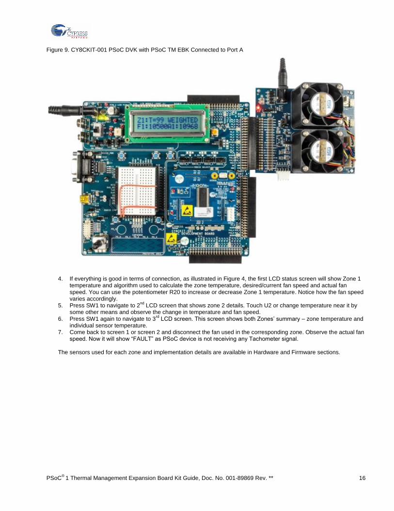
Figure 9. CY8CKIT-001 PSoC DVK with PSoC TM EBK Connected to Port A
4. If everything is good in terms of connection, as illustrated in Figure 4, the first LCD status screen will show Zone 1 temperature and algorithm used to calculate the zone temperature, desired/current fan speed and actual fan speed. You can use the potentiometer R20 to increase or decrease Zone 1 temperature. Notice how the fan speed varies accordingly.
5. Press SW1 to navigate to 2nd
LCD screen that shows zone 2 details. Touch U2 or change temperature near it by some other means and observe the change in temperature and fan speed.
6. Press SW1 again to navigate to 3rd
LCD screen. This screen shows both Zones’ summary – zone temperature and individual sensor temperature.
7. Come back to screen 1 or screen 2 and disconnect the fan used in the corresponding zone. Observe the actual fan speed. Now it will show “FAULT” as PSoC device is not receiving any Tachometer signal.
The sensors used for each zone and implementation details are available in Hardware and Firmware sections.

PSoC®
1 Thermal Management Expansion Board Kit Guide, Doc. No. 001-89869 Rev. ** 17
4. Hardware
Board Details
This section provides an overview of the PSoC TM EBK hardware. The PSoC TM EBK contains two 4-wire, 12-V brushless DC fans with connectors to support an additional two fans for designers who need to prototype with their own specific fan models. Six temperature sensors (four different kinds) are also installed on the kit:
One TMP175 I2C digital temperature sensor
Two TMP05 PWM temperature sensors One DS18S20 1-wire digital temperature sensor Two MMBT3094 temperature diodes
This combination of hardware elements enables you to rapidly prototype thermal management solutions in a variety of configurations.
The PSoC TM EBK also provides an I2C/SMBus/PMBus-compatible header to support systems that have a requirement for
communication with a host controller. All of this functionality is implemented on a single PSoC 1. The PSoC TM EBK routes all the input and output signals for thermal management to a PSoC 1 mounted on a development kit platform such as the CY8CKIT-001. PSoC 1 is not mounted on the PSoC TM EBK.
Figure 10 shows PSoC TM EBK hardware components. Kit enables you to control up to four 4-wire fans using MCU-based control. Independent hardware PWM blocks in PSoC 1 generate fan drive signals to drive the 4-wire fans. PSoC 1 interprets tachometer signals from the fans to determine fan rotational speeds. The firmware running on PSoC 1 achieves speed control to the desired RPM. The firmware also detects fan stall or rotor lock faults.
To support digital sensor temperature sensing, standard PSoC 1 interfaces are used where possible (such as I2C); PSoC
user modules have been developed for nontypical digital temperature sensors such as the PWM temperature sensor (TMP05) and the 1-wire temperature sensor. For analog sensors, PSoC 1 also provides onboard filtering, multiplexing for better resolution, and accurate temperature sensor measurement.
The example project provided with the PSoC TM EBK illustrates how to aggregate temperature sensor readings using a variety of methods. The resultant “zone temperature” is used to set individual fan speeds. This is defined as a “thermal zone.” The example project shows how you can configure each fan to be dependent on any of the available temperature sensors in any combination. It also demonstrates how you can use the composite zone temperature to determine the required fan speed to achieve system cooling needs.
Although not included in the example project, PSoC 1 devices also include nonvolatile EEPROM memory that you can use to store sensor calibration information or for event and fault logging purposes. Communication with a host controller or management processor can be achieved via I
2C, SMBus, PMBus, or a variety of other communications protocols
implemented with easy-to-use PSoC 1 user modules.
Note that PSoC TM EBK hardware limits support to a maximum of four fans. You can easily extend the PSoC 1 Thermal Management solution to support up to 10 fans in a single device. Contact Cypress for further information on the full PSoC 1 Thermal Management solution.

PSoC®
1 Thermal Management Expansion Board Kit Guide, Doc. No. 001-89869 Rev. ** 18
Figure 10. CY8CKIT-036 Hardware Components

PSoC® 1 Thermal Management Expansion Board Kit Guide, Doc. No. 001-89869 Rev. ** 19
2x20 Pin Header
The 40-pin interface (2x20 pin header) provides a mechanism to connect PSoC TM EBK to a Cypress development kit platform. Table 2 lists the pin assignments of the 2x20 connector.
Table 2. 20x20 Connector Pin Assignments
Description Signal Pin Pin Signal Description
Tachometer signal from Fan 4 TACH4 1 2 PWM4 PWM speed control for Fan 4
Tachometer signal from Fan 3 TACH3 3 4 PWM3 PWM speed control for Fan 3
Tachometer signal from Fan 2 TACH2 5 6 PWM2 PWM speed control for Fan 2
Tachometer signal from Fan 1 TACH1 7 8 PWM1 PWM speed control for Fan 1
Analog Ground AGND 9 10 NC –
– NC 11 12 NC –
– NC 13 14 NC –
– NC 15 16 NC –
– NC 17 18 NC –
Analog Ground AGND 19 20 NC –
Temperature diode current source TD-I 21 22 TD-K Temperature diode cathode
Temperature diode anode TD-A 23 24 1-WIRE 1-wire temperature sensor
I2C temperature sensor output T-SDA 25 26 T-SCL I
2C temperature sensor clock
PWM temperature sensor output P-OUT 27 28 P-IN PWM temperature sensor input
Analog Ground AGND 29 30 NC –-
Reserved RESV 31 32 SM-ALT Alert signal (I2C/SMBus/PMBus)
Serial data (I2C/SMBus/PMBus) SM-SDA 33 34 SM-SCL Serial clock (I
2C/SMBus/PMBus)
3.3-V power from DVK 3.3 V 35 36 VADJ Unused
Digital Ground DGND 37 38 5 V 5 V-power from DVK
Optional 12-V power from DVK 12 V 39 40 DGND Digital Ground

PSoC®
1 Thermal Management Expansion Board Kit Guide, Doc. No. 001-89869 Rev. ** 20
CY8CKIT-036 Headers and Jumpers
A number of jumpers are provided on the PSoC TM EBK. Table 3 lists the default jumper settings for the board.
Table 3. CY8CKIT-036 Jumper Settings
Headers and
Jumpers Description Factory Default Configuration
J1 5-pin header for connecting an external host or management processor via I2C/SMBus/PMBus. Connector fitted
J2 3-pin header to choose between single-sensor and dual-sensor (daisy chain) connection for the PWM temperature sensors. Place jumper in 1-2 position to enable dual-sensor daisy-chain mode.
1-2 position (dual-sensor daisy chain)
J3 J3 3-pin header to set logic signal levels for digital temperature sensors. Place in 1-2 position for 5-V interfacing; place in 2-3 position for 3.3-V interfacing.
2-3 position (3.3-V interfacing )
J4 4-pin header (1.25 mm pitch) to connect Fan 1. Supplies 12-V power, ground, PWM drive, and tachometer feedback. All signals are replicated on J7. Not connected
J5 4-pin header (1.25 mm pitch) to connect Fan 2. Supplies 12-V power, ground, PWM drive, and tachometer feedback. All signals are replicated on J8. Not connected
J6 4-pin header (1.25 mm pitch) to connect Fan 3. Supplies 12-V power, ground, PWM drive, and tachometer feedback. All signals are replicated on J10. Not connected
J7 4-pin header (2.54 mm pitch) to connect Fan 1. Supplies 12-V power, ground, PWM drive, and tachometer feedback. All signals are replicated on J4.
Connected to Fan 1
J8 4-pin header (2.54 mm pitch) to connect Fan 2. Supplies 12-V power, ground, PWM drive, and tachometer feedback. All signals are replicated on J5.
Connected to Fan 2
J9 3-pin header for fan power supply. Place in 1-2 position to source external power from the power jack (J13); place in 2-3 position to source 12-V power from the DVK.
1-2 position (fan power from J13)
J10 4-pin header (2.54 mm pitch) to connect Fan 3. Supplies 12-V power, ground, PWM drive, and tachometer feedback. All signals are replicated on J6. Not connected
J11 4-pin header (2.54 mm pitch) to connect Fan 4. Supplies 12-V power, ground, PWM drive, and tachometer feedback. All signals are replicated on J12. Not connected
J12 4-pin header (1.25 mm pitch) to connect Fan 4. Supplies 12-V power, ground, PWM drive, and tachometer feedback. All signals are replicated on J11. Not connected
J13 Power jack. 12-V DC nominal. Connector fitted
J14 2×20 pin header for connecting to the PSoC DVK. Connector fitted
J15 2×20 pin header that replicates signals on J14 for easy connection to a logic analyzer or oscilloscope. Open
PWM Temperature Sensors
The TMP05 PWM output digital temperature sensor is a monolithic temperature sensor that generates a modulated serial digital output (PWM) signal. The duty cycle of this PWM signal is proportional to the ambient temperature measured by the device. The high period (TH) of the PWM remains generally static over all temperatures, while the low period (TL) varies. The ratio of TH/TL provides a method for determining the temperature according to the formula, temperature (°C) = 421 – (751 × TH/TL). The TMP05 sensors have a 2-pin interface; a CONV/IN input that when pulsed by PSoC, initiates a new temperature measurement; and an OUT output, which provides a PWM signal that you can decode using the temperature formula to determine ambient temperature. The TMP05 sensors support a daisy-chain mode of operation, where the OUT signal of the first sensor can be directly connected to the CONV/IN input of the subsequent sensor. The OUT of the second sensor carries the PWM signals from both sensors. Many sensors can be daisy-chained in this fashion, with the final OUT signal carrying the PWM temperature encoding from all sensors in the daisy chain. This sensor is generally operated in either the one-shot mode or continuous mode.
For more details, refer to the TMP05 device datasheet, which is available on the device manufacturer's website or under the datasheet folder at the installation location. Application note AN78737 – PSoC 1 – Temperature Sensing Solution using a TMP05/TMP06 Digital Temperature Sensor discusses details about the digital temperature sensor and the implementation in PSoC 1 with an example project.

PSoC® 1 Thermal Management Expansion Board Kit Guide, Doc. No. 001-89869 Rev. ** 21
I2C Digital Temperature Sensors
PSOC TM EBK demonstrates an I2C temperature sensing capability using a 2-wire I
2C compatible digital temperature
sensor, the TMP175. I2C digital temperature sensors are common sensors for thermal management and are used in a
variety of communication, computer, consumer, environmental, industrial, and instrumentation applications due to the popularity of the I
2C bus. For more details, refer to its datasheet, which is available on the manufacturer's website or under
the datasheet folder at the installation location. Application note AN2163 – Interfacing to 1-Wire/Two-Wire Digital Temperature Sensors using PSoC 1 discusses details about the digital temperature sensor and the implementation in PSoC 1 with an example project.
1-Wire Digital Temperature Sensors
PSOC TM EBK has a Maxim DS18S20 1-wire high-precision digital temperature sensor installed. The DS18S20 digital thermometer provides 9-bit resolution Celsius temperature measurements and has an alarm function with nonvolatile user-programmable upper and lower trigger points. The DS18S20 communicates over a proprietary 1-wire bus that by definition requires only one data line (and ground) to communicate with a host microprocessor. It has an operating temperature range of –55 °C to +125 °C. For more details, refer to its datasheet, which is available on the manufacturer's website or under the datasheet folder at the installation location. Application note AN2163 – Interfacing to 1-Wire/Two-Wire Digital Temperature Sensors using PSoC 1 discusses details about the digital temperature sensor and the implementation in PSoC 1 with an example project.
Diode Analog Temperature Sensors
MMBT3904 is a bipolar junction transistor (BJT) designed as a general-purpose amplifier and switch. The useful dynamic range extends to 100 mA as a switch and to 100 MHz as an amplifier. You can use the delta Vbe method described in application note AN78920 – PSoC 1 Temperature Measurement Using Diode with PSOC TM EBK; the application note discusses the operation theory and relevant mathematical equations. The implementation is primarily driven by firmware due to the complexities associated with varying the source current fed to the BJT, filtering the ADC measurements, and calibrating the analog subsystem, all of which are required to achieve sufficiently high accuracy with these low-cost temperature sensors.
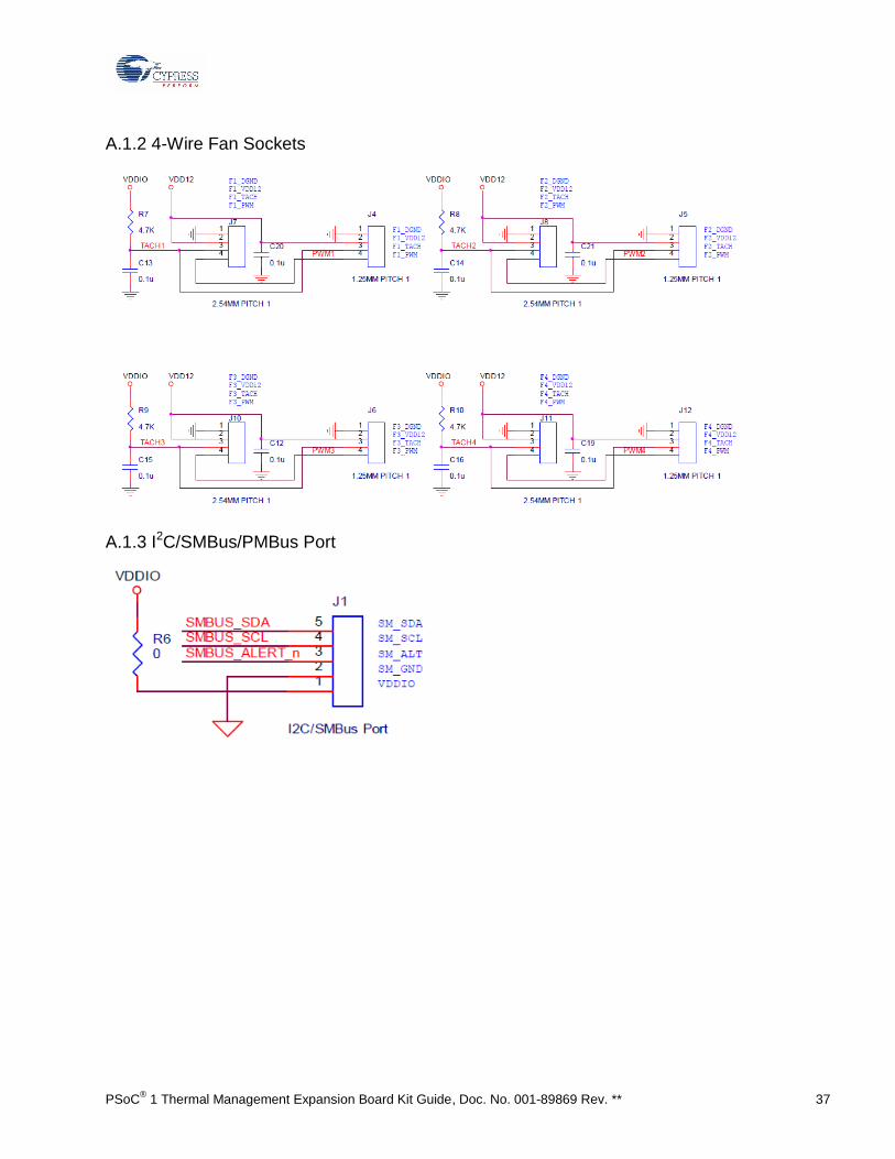
4-Wire Fan Connectors
The PSOC TM EBK provides four industry-standard 4-wire fan interface connectors and two AVC 12-V brushless DC fans. For the fans that are mounted on the EBK,speeds are controllable up to 12,700 RPM via PWM control, with tachometer output to calculate actual fan speeds. For more details, refer to its datasheet, which is available on the manufacturer's website or under the datasheet folder at the installation location.
Table 4. Fan Connector Pinouts
Pin Number Name Colors Description
1 GND Black Ground
2 POWER Red 12-V DC power
3 TACH Yellow Frequency generator signal
4 PWM Blue PWM control signal

PSoC®
1 Thermal Management Expansion Board Kit Guide, Doc. No. 001-89869 Rev. ** 22
5. Example Project
The example project is available at <Install_Directory>\Cypress\PSoC 1 Thermal Management EBK\1.0\firmware.
Note: The default installation location is C:\Program Files\Cypress\PSoC 1 Thermal Management EBK\1.0 for 32-bit
machines and C:\Program Files(x86)\Cypress\PSoC 1 Thermal Management EBK\1.0 for 64-bit machines.
Overview
This example project demonstrates how the temperature sensors combined with the fans on the PSOC TM EBK can create a complete thermal management system. The example shows how to combine temperature readings from a number of temperature sensors in a variety of ways and use the composite temperature to set desired fan speeds according to a customized transfer function.
The thermal management example project uses the concept of a “thermal zone.” A thermal zone describes the following:
How to combine multiple temperature sensor readings to form a composite zone temperature How to map the zone temperature to a fan speed.
By this definition, each fan will be controlled according to its own independent thermal zone. This example has two thermal zones because PSOC
TM EBK has only two fans installed. Algorithms currently implemented to combine multiple
temperature sensors into a composite zone temperature include straight average, weighted average, and maximum. Straight average algorithm returns the average value of all the sensors used in that particular zone. Weighted average algorithm first applies the weight to each sensor temperature as defined in the zone configuration and then takes the average of the resultant number. Maximum algorithm simply returns the maximum temperature from sensors in that particular zone. Algorithm for a particular zone can be selected by changing the zone configuration.
This example project uses the weighted method on both fans. A zone temperature to fan speed transfer function is then definable for each zone. In this project, the transfer function used is table driven on both fans; that is, a lookup table maps composite zone temperature to fan speed.
Two temperature zones: Zone 1 and Zone 2 Two 4-wire BLDC fans: Fan 1 and Fan 2 installed in Zone 1 and Zone 2, respectively Four temperature sensors
Table 5. Zone Configuration
Label Temperature Sensor To Be Installed In Weight
U1 in CY8CKIT-036 I2C output temperature sensor – TMP175 Zone 1 10%
R20 in CY8CKIT-001 Diode temperature sensor 90%
U2 in CY8CKIT-036 1-wire temperature sensor – DS1820 Zone 2 90%
U3 in CY8CKIT-036 PWM temperature sensor – TMP05 10%
This example is a simulation of a thermal management system. The first zone, Zone 1, combines temperature measurements from two temperature sensors (one analog and one digital). The analog sensor is simulated using a variable potentiometer to allow easy demonstration of fan control over a wide simulated temperature range without the need for an environmental chamber to cycle through temperatures. In Zone 1, the temperature sensors are combined using a weighted

PSoC® 1 Thermal Management Expansion Board Kit Guide, Doc. No. 001-89869 Rev. ** 23
average, where the potentiometer is given a 90% weight and the I2C digital temperature sensor (U1 on PSOC TM EBK) is
given a 10% weight. You can adjust the potentiometer (R20 on the CY8CKIT-001 DVK) to vary the simulated temperature value. The Zone 1 speed transfer function is table driven and follows the profile shown in Table 6. When temperature increases, temperature vs speed will be as shown in Table 6. However, when temperature decreases, speed will decrease only when temperature change is more than hysteresis. For example, when temperature is decreasing, speed will change at 30 degree if current temperature is 35 degree or above. This is due to the reason that hysteresis is set to 4 for zone 1.
Table 6. Zone 1 Thermal Profile
Temperature (°C) Fan Speed (RPM)
0–14 5,000
15–34 5,500
35–54 6,500
55–74 8,500
>=75 10,500
Zone 2 consists of two temperature sensors and a single fan. The Zone 2 speed transfer function is table driven and is shown in Table 7. Note that the temperature range is narrow and close to room temperature. This is to allow for simple testing at room temperature by just touching a temperature sensor with a warm finger to cause a fan speed change. In Zone 2, the temperature sensors are combined using a weighted average, where the 1-wire temperature sensor (U2 on PSOC TM EBK) is given a 90% of the weight. The PWM temperature sensor (U3 on PSOC TM EBK) is given a 10% weight. In this example, U2’s temperature reading will dominate the overall zone temperature calculation.
When temperature increases, temperature vs speed will be as shown in Table 7. However, when temperature decreases, speed will decrease only when temperature change is more than hysteresis. For example, when temperature is decreasing, speed will change at 25 degree if current temperature is 27 degree or above. This is due to the reason that hysteresis is set to 1 for zone 2.
Table 7. Zone 2 Thermal Profile
Temperature (°C) Fan Speed (RPM)
0–22 5,000
23–24 6,000
25–26 7,000
27–28 9,000
>=29 10,000
The LCD screen displays status information about the thermal management system across three screens. You can cycle through the status screens by pressing SW1 on the CY8CKIT-001 DVK.
Screen 1 – Zone 1 Summary
This screen shows the current status of Zone 1, as illustrated in Figure 11. Line 1 displays the zone number, the current composite zone temperature, and the zone temperature calculation algorithm used. Line 2 displays the desired fan speed and the actual fan speed for Zone 1.
Note: Actual fan speed may not be same as the desired. Maximum tolerance can be 5%.
Figure 11. Zone 1 Summary

PSoC®
1 Thermal Management Expansion Board Kit Guide, Doc. No. 001-89869 Rev. ** 24
Screen 2 – Zone 2 Summary
This screen shows the current status of Zone 2, as illustrated in Figure 12. Line 1 displays the zone number, the current composite zone temperature, and the zone temperature calculation algorithm used. Line 2 displays the desired fan speed and the actual fan speed for Zone 2.
Note: Actual fan speed may not be same as the desired. Maximum tolerance can be 5%.
Figure 12. Zone 2 Summary
Screen 3 – Temperature Sensor Summary
This screen shows the current temperature sensor readings for all sensors in the system, as displayed in Figure 13. Line 1 displays the Zone 1 temperature sensor values. The leftmost temperature is the zone’s composite temperature, followed by the temperatures of each contributing sensor. Line 2 displays the same information for Zone 2.
Figure 13. Temperature Sensor Summary
Technical Details
High-Level Architecture
Figure 14 shows the high-level architecture inside PSoC 1.

PSoC® 1 Thermal Management Expansion Board Kit Guide, Doc. No. 001-89869 Rev. ** 25
Figure 14. Thermal Management Functional Block Diagram
PSoC 1 Resource Usage Details
Table 8 lists the resources used inside PSoC 1.
Table 8. Resource Usage
IP Functions Digital Blocks Analog Blocks Pins
Fan controller Fan controller 6 1 4 (2 per fan)
TMP05 16-bit timer 2 0 1
I2C I
2C HW 0 0 2
Analog sensor PGA
ADC
1 2 1
OneWire Transceiver
Clock
3 0 2
Global Resources
Figure 15 shows the window used to set the global resource parameters.
Ref Mux setting (Vdd/2)+/-(Vdd/2) sets the ADC measurement range to 0V to 3.3V
Timer
One wire
I2Cm
14 Bit
ADCINCPGA
Interrupt
M8C
4MIPS
16K Flash
1K SRAM
I2C
Clocks
Voltage
Reference
External
Host
FANs
Tachometer
feedback
PWM output
1 Wire
I2C output
Diode
Temperature Sensors
Communication Global resources Analog and Digital functions
PSoC 1
Fan Controller

PSoC®
1 Thermal Management Expansion Board Kit Guide, Doc. No. 001-89869 Rev. ** 26
The VC1 clock of 1.6MHz drives the ADCINC User Module. This gives the sample rate as 24 sps.
Figure 15. Global Resource Parameters
FanController configuration:
Two fan banks are used.
One analog mux bus is used for TACH input connection.
Closed-loop speed regulation is implemented.
An alert is generated when the fan is stalled.
The Fans tab settings are based on the fan used on TM EBK. The settings entered are based on the fan datasheet. If a different fan is used, change these settings.
Pins are assigned per the PSoC TM EBK connection on Port A of the CY8CKIT-001.

PSoC® 1 Thermal Management Expansion Board Kit Guide, Doc. No. 001-89869 Rev. ** 27
Figure 16. Fan Controller
Fan Controller MUM Selection
User Module PSoC Designer Screen

PSoC®
1 Thermal Management Expansion Board Kit Guide, Doc. No. 001-89869 Rev. ** 28
Fan Controller Wizard – Basic Tab
Fan Controller Wizard – Fans Tab

PSoC® 1 Thermal Management Expansion Board Kit Guide, Doc. No. 001-89869 Rev. ** 29
Fan Controller Wizard – Pinout Tab
In TMP05, PulseWidthTimer is the 16-bit timer used to measure pulse width for PWM-based temperature sensors, as shown in Figure 17.
Figure 17. TMP05 (Timer16)
User Module Parameters

PSoC®
1 Thermal Management Expansion Board Kit Guide, Doc. No. 001-89869 Rev. ** 30
User Module PSoC Designer Screen
PGA takes the input from a potentiometer, which is used to simulate the diode sensor output. The PGA gain is set to 1, as shown in Figure 18.
Figure 18. Buffer (PGA)
ADCINC reads the voltage from the potentiometer (simulated diode sensor). Figure 19 shows the following:
The resolution is set to 14 bits.
The sample rate is set to 24 sps
The input for this user module is taken from PGA.
User Module Parameters
User Module PSoC Designer Screen

PSoC® 1 Thermal Management Expansion Board Kit Guide, Doc. No. 001-89869 Rev. ** 31
Figure 19. ADC (ADCINC)
User Module Parameters
OneWire is the 1-wire communication user module to read temperature data from the 1-wire temperature sensor, as shown in Figure 20. PWM_OneWire supplies the input clock to the OneWire User Module.
Figure 20. OneWire
User Module Parameters for OneWire User Module
User Module PSoC Designer Screen

PSoC®
1 Thermal Management Expansion Board Kit Guide, Doc. No. 001-89869 Rev. ** 32
User Module Parameters for PWM_OneWire (PWM8) User Module used for clock generation for OneWire User Module
LCD User Module is used to display temperature, fan speed and fan status on 16x2 character LCD. LCD uses Port 2 as shown in Parameters window in Figure 21.
Figure 21. LCD
User Module Parameters
I2Cm is the User Module for I2C Master. It is used to interface I2C temperature sensor. Pins P4.3 and P4.2 are used for I2C communication as shown in Parameters window in
Figure 22.
Figure 22. I2Cm
User Module Parameters
User Module PSoC Designer Screen

PSoC® 1 Thermal Management Expansion Board Kit Guide, Doc. No. 001-89869 Rev. ** 33
Firmware Structure
The Thermal Management System example consists of dedicated .c and .h files for every function (see Figure 23). You can remove any function you do not need by removing the associated .c and .h file. The main application is responsible for the user interface and for periodically calling the thermal manager. The application implementation can be found in main.c. The thermal manager implementation can be found in ThermalManager.
The main application needs to call ThermalManager_Start() only to initialize the thermal manager, and then it must periodically call ThermalManager_Service() and then call LCD_Menu() to run temperature and speed updates.
All the parameters that define the zone composite temperature sensor algorithm and the zone temperature to fan speed algorithm are defined at the top of thermalmanager.c. To modify these settings, refer to thermalmanager.h for the relevant keywords
Figure 23. Workspace Explorer
The entries in Table 6 and Table 7 are defined in the highlighted boxes in Figure 24. You can change temperature versus fan speed entries based on design requirements.

PSoC®
1 Thermal Management Expansion Board Kit Guide, Doc. No. 001-89869 Rev. ** 34
Figure 24. Zone Temperature Versus Fan Speed Lookup Table
You can also change the key zone configuration parameters shown in Figure 25 based on design requirements. In this figure, the red highlighted box shows where the weights for different temperature sensors are entered. See Table 5 for details.
The blue highlighted box shows where the hysteresis for both the zones is set. Hysteresis has been defined to avoid unnecessary fan speed changes in the temperature borders of the lookup table. For example, if the Zone 1 temperature varies between 34.9 °C and 35.1 °C, the fan speed will be fluctuating between 5,500 and 6,500 RPM. To avoid this, hysteresis logic is implemented in the firmware. In this case, it is defined as “4,” which means that if the temperature changes from 34.9 °C to 35 °C, the fan speed will change from 5,500 to 6,500 RPM, but if the temperature again falls from 35 °C, the fan speed will not change until 31 °C to avoid unnecessary speed fluctuations in the border. You can change this entry according to design requirements.
Figure 25. Zone Configuration

PSoC® 1 Thermal Management Expansion Board Kit Guide, Doc. No. 001-89869 Rev. ** 35
Firmware Flowchart
Figure 26 displays the basic function of the thermal manager inthermalmanager.c, which implements the main service loop.
Figure 26. Thermal Manager Flowchart

PSoC®
1 Thermal Management Expansion Board Kit Guide, Doc. No. 001-89869 Rev. ** 36
Appendix A: Schematics, Layout, and Components
A.1 CYC8CKIT-036 Schematics
A.1.1 Power Supply
PSoC® 1 Thermal Management Expansion Board Kit Guide, Doc. No. 001-89869 Rev. ** 37
A.1.2 4-Wire Fan Sockets
A.1.3 I2C/SMBus/PMBus Port

PSoC®
1 Thermal Management Expansion Board Kit Guide, Doc. No. 001-89869 Rev. ** 38
A.1.4 2x20 Pin DVK Connector and Test Points
A.1.5 1-Wire Temperature Sensor
A.1.6 Temperature Diodes

PSoC® 1 Thermal Management Expansion Board Kit Guide, Doc. No. 001-89869 Rev. ** 39
A.1.7 I2C Temperature Sensors
A.1.8 PWM Temperature Sensors

PSoC®
1 Thermal Management Expansion Board Kit Guide, Doc. No. 001-89869 Rev. ** 40
A.2 CY8CKIT-036 Board Layout
A.2.1 Top Layer

PSoC® 1 Thermal Management Expansion Board Kit Guide, Doc. No. 001-89869 Rev. ** 41
A.2.2 Bottom Layer

PSoC®
1 Thermal Management Expansion Board Kit Guide, Doc. No. 001-89869 Rev. ** 42
A.2.3 Top Silkscreen

PSoC® 1 Thermal Management Expansion Board Kit Guide, Doc. No. 001-89869 Rev. ** 43
A.3 CY8CKIT-036 Bill of Materials
Item Description Qty Reference PCB
Footprint Manufact
urer Mfr Part Number
1 MLCC, 0.1uF, +/-10%, 25V, X5R(0402) 15
C2,C5,C7,C11,C12,C13,C14,C15,C16,C17,C18,C19,C20,C21,C22 C-0402
Taiyo Yuden
TMK105BJ104KV-F
2 MLCC, 22uF, +/-10%, 25V, X5R(1210) 1 C8 C-1210 MURATA
GRM32ER61E226KE15L
3 MLCC, 10uF, +/-10%, 25V, X5R(1206) 3 C9,C10,C23 C-1206 MURATA GRM31CR61E106KA12
4 Schottky Rectifier, 40V/3A(SM340A) 4 D1,D2,D3,D5 DO-214AC GW SM340A
5 Yellow LED 1 D4 LED-0805 LITEON LTST-C170KSKT
6 1X3 .100"CENTER HEADER 3 J2,J3,J9
CON-1X3_2-54MM SAMTEC
TSW-103-07-G-S
7 FAN socket, 1.25mm Wafer 180° 4 J4,J5,J6,J12 FAN_CON4_1-25MM
CHERNG WEEI
CCX-W125-04-DIP
8 FAN socket, 2.54mm Wire-to-Board Header, DIP 180° Type 4 J7,J8,J10,J11
FAN_CON4P
CHERNG WEEI
CD-W254-(3.4)
9 DC JACK 1 J13 JACK-DC_2mm
CHERNG WEEI 32753PA
10 CONN HEADER 40POS .100 R/A TIN 1 J14
CON-2X20R_2-54mm
CHERNG WEEI
P201-R1GP-060/030-40
11 NPN General Purpose Amplifier, SOT-23(MMBT3904) 2 Q1,Q2 SOT-23
FAIRCHILD MMBT3904
12 10K ohm, +/-1%, 1/16W (0402) 1 R1 R-0402 YAGEO RC0402FR-0710KL
13 2.2K ohm, +/-1%, 1/16W(0402) 2 R2,R3 R-0402 YAGEO RC0402FR-072K2L
14 4.7K ohm, +/-1%, 1/16W(0402) 5 R4,R7,R8,R9,R10 R-0402 YAGEO RC0402FR-074K7L
15 1K ohm, +/-0.1%, 1/16W(0402) 1 R5 R-0402 SAMSUNG
RG1005P-102-B-T5
16 0 ohm, Jumper, 1/10W(0603) 2 R6,R11 R-0603 WALSIN WR06X000 PTL
17 Digital Temperature Sensor with Two-Wire Interface 1 U1 SOIC-8 TI TMP75AID
18 High-Precision 1-Wire Digital Thermometer 1 U2 SOIC-8 MAXIM DS18S20Z
19 ±0.5°C Accurate PWM Temperature Sensor in 5-Lead SC-70 2 U3,U4 SOT-23
Analog Devices, Inc. TMP05ART
20 BUMPER CLEAR.370X.19" CYLINDER 4 MH1,MH2,MH3,MH4 Richco RBS-35
21 MINI Jumper,2PIN 3 J2(1-2),J3(1-2),J9(1-2) NA CHERNG WEEI CMJ-135BB
22 M3 35mm 8 CHIN SCREW 3-0.5*35
23 Stainless Screw, Nut 16 CHIN SN03
24 DC FAN 40x28mm, 12V, 2Ball Bearing, 4wire, 13000rpm, PWM control 2 AVC
DB04028B12UP090
25 [TME] PCB, Thermal Management EBK PCB, REV A 1 FHT
10-3101227-A0
26 5 pin CONN HEADER, 2.54mm, Through Hole, Right Angle, Friction Lock 1 J1
FAN_CON5R MOLEX 22-05-3051
No Load Components
27 PIN Header, MA, ST, DIP, 2*20 PIN, P2.54mm, I2.54 mm 1 J15
CHERNG WEEI
P201-SGP-060/030-40
28 MLCC, 4.7uF, +/-10%, 6.3V, X5R(0603) 4 C1,C3,C4,C6 YAGEO CC0603KRX5R5BB475

PSoC®
1 Thermal Management Expansion Board Kit Guide, Doc. No. 001-89869 Rev. ** 44
Revision History
Document Revision History
Document Title: PSoC® 1 Thermal Management Expansion Board Kit Guide
Document Number: 001-89869
Revision Issue Date Origin of
Change
Description of Change
** 10/31/2013 SGUP New kit guide.