
PSB H 0 -H - Injection: Sectorisation Analysis C.Pasquino, J. Hansen, P.Chiggiato LIU - PSB Ho-H-...
13
PSB H 0 -H - Injection: Sectorisation Analysis C.Pasquino, J. Hansen, P.Chiggiato LIU - PSB Ho-H- Injection Meeting 1
-
Upload
ginger-conley -
Category
Documents
-
view
218 -
download
0
Transcript of PSB H 0 -H - Injection: Sectorisation Analysis C.Pasquino, J. Hansen, P.Chiggiato LIU - PSB Ho-H-...
LIU
- PS
B H
o-H
- Inj
ectio
n M
eetin
g
PSB H0-H- Injection: Sectorisation Analysis
C.Pasquino, J. Hansen, P.Chiggiato
1
LIU
- PS
B H
o-H
- Inj
ectio
n M
eetin
g
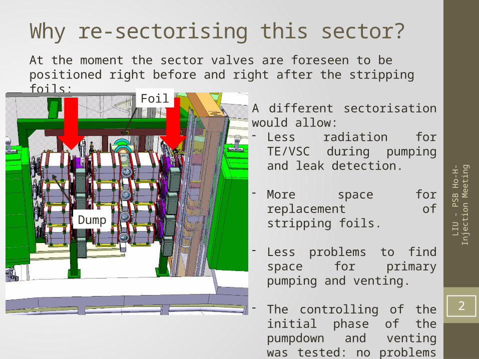
Why re-sectorising this sector?At the moment the sector valves are foreseen to be positioned right before and right after the stripping foils;
2
A different sectorisation would allow:- Less radiation for TE/VSC during
pumping and leak detection.
- More space for replacement of stripping foils.
- Less problems to find space for primary pumping and venting.
- The controlling of the initial phase of the pumpdown and venting was tested: no problems occurred (report under validation).
Foil
Dump
LIU
- PS
B H
o-H
- Inj
ectio
n M
eetin
g
Several Case Study (1)
3
Option1
Option2
Option3
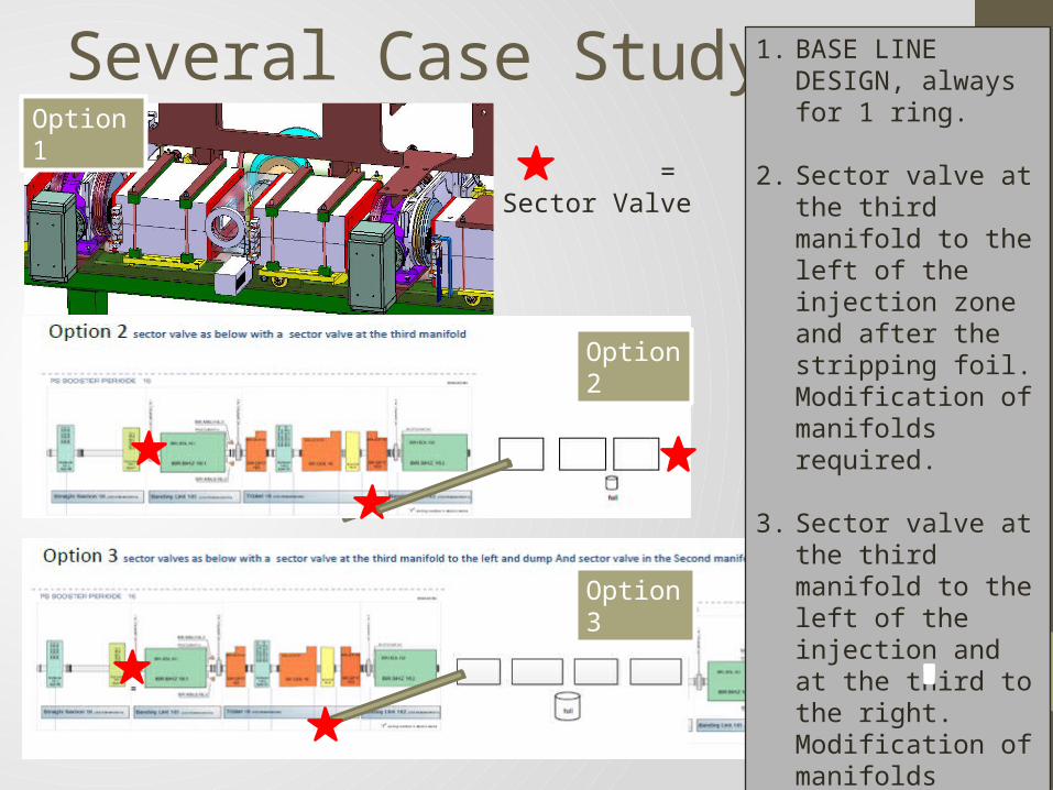
1. BASE LINE DESIGN, always for 1 ring.
2. Sector valve at the third manifold to the left of the injection zone and after the stripping foil. Modification of manifolds required.
3. Sector valve at the third manifold to the left of the injection and at the third to the right. Modification of manifolds required.
= Sector Valve
LIU
- PS
B H
o-H
- Inj
ectio
n M
eetin
g
Several Case Study (2)
4
Option 4
Option 5
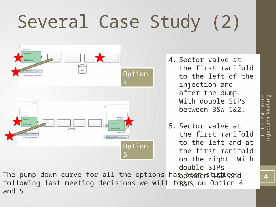
4. Sector valve at the first manifold to the left of the injection and after the dump. With double SIPs between BSW 1&2.
5. Sector valve at the first manifold to the left and at the first manifold on the right. With double SIPs between 1&2 and 3&4.
The pump down curve for all the options has been studied: following last meeting decisions we will focus on Option 4 and 5.
LIU
- PS
B H
o-H
- Inj
ectio
n M
eetin
g
Pump down studies: option 1
5
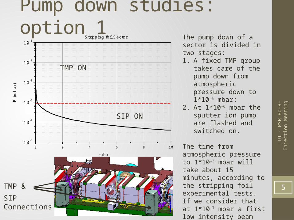
The pump down of a sector is divided in two stages:1. A fixed TMP group takes
care of the pump down from atmospheric pressure down to 1*10-6 mbar;
2. At 1*10-6 mbar the sputter ion pump are flashed and switched on.
The time from atmospheric pressure to 1*10-3 mbar will take about 15 minutes, according to the stripping foil experimental tests.If we consider that at 1*10-7 mbar a first low intensity beam can be sent 5 to 6 hours after the end of the intervention including the leak detections, if the dumps are conditioned before.
0 2 4 6 8 1010-8
10-7
10-6
10-5
10-4
10-3
P (m
bar)
t (h)
Stripping foil Sector
SIP ON
TMP ON
SIP Connections
TMP &
LIU
- PS
B H
o-H
- Inj
ectio
n M
eetin
g
Pump down studies: option 4
6
TMP gate
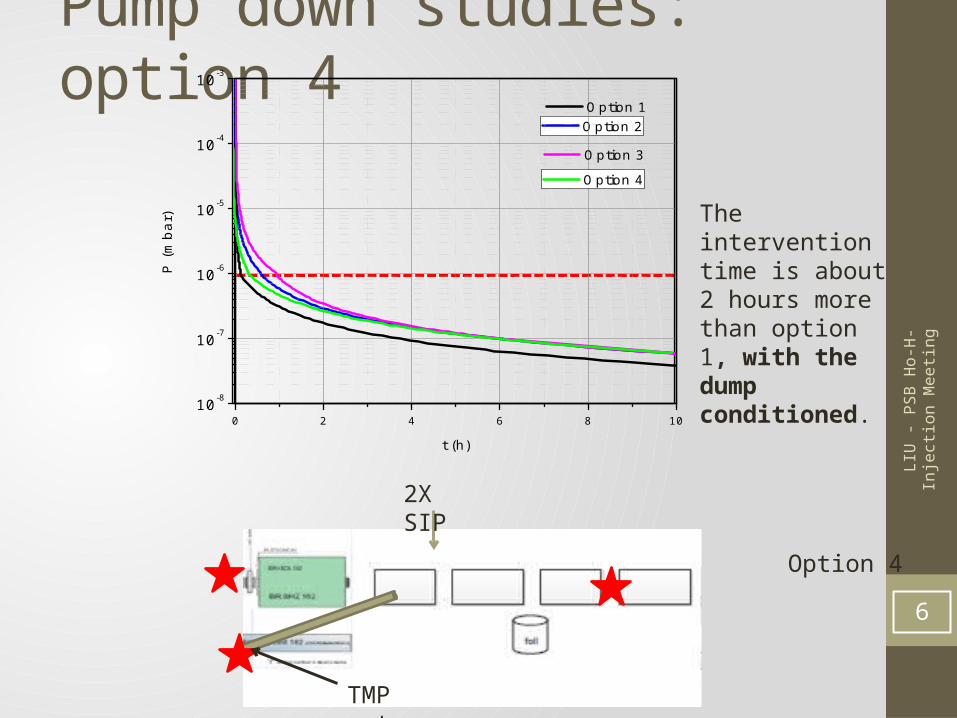
2X SIP
Option 2
0 2 4 6 8 1010-8
10-7
10-6
10-5
10-4
10-3
Option 1
P (m
bar)
t (h)
Option 4
Option 3
Option 4
The intervention time is about 2 hours more than option 1, with the dump conditioned.
LIU
- PS
B H
o-H
- Inj
ectio
n M
eetin
g
Evaluation of the conditioning time for option 5
7
0 1 2 3 4 5 6 7 8 90
50
100
150
200
250
300
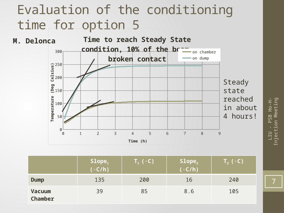
Time to reach Steady State condition, 10% of the beam, broken contact
on chamberon dump
Time (h)
Tem
pera
ture
(Deg
Cel
sius)
Slope1 (◦C/h) T1 (◦C) Slope2 (◦C/h) T2 (◦C)
Dump 135 200 16 240
Vacuum Chamber 39 85 8.6 105
Steady state reached in about 4 hours!
M. Delonca
LIU
- PS
B H
o-H
- Inj
ectio
n M
eetin
g
Evaluation of the conditioning time for option 5
8
0 2 4 6 8 10 12 14 16 18 2010-8
10-7
10-6
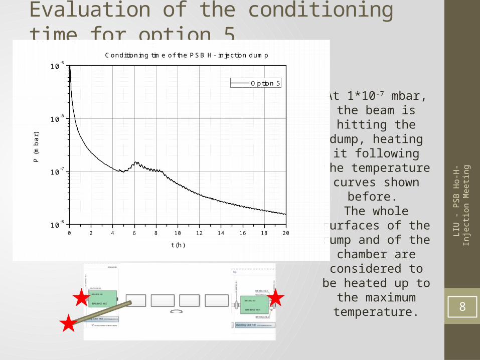
10-5Conditioning time of the PSB H- injection dump
P (m
bar)
t (h)
Option 5
At 1*10-7 mbar, the beam is hitting the dump, heating it
following the temperature curves
shown before. The whole surfaces of the dump and of the
chamber are considered to be heated up to the
maximum temperature.
LIU
- PS
B H
o-H
- Inj
ectio
n M
eetin
g
Evaluation of the conditioning time for option 5
9
0 2 4 6 8 10 12 14 16 18 2010-8
10-7
10-6
10-5Conditioning time of the PSB H- injection dump
P (m
bar)
t (h)
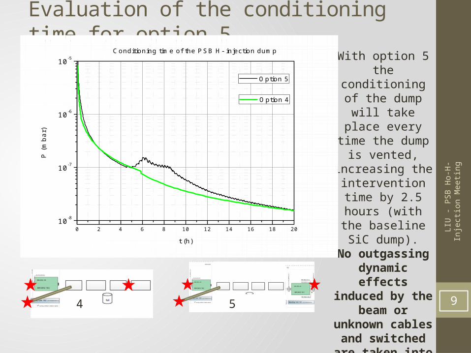
Option 5
Option 4
With option 5 the conditioning of the
dump will take place every time the
dump is vented, increasing the
intervention time by 2.5 hours (with the baseline SiC dump).
No outgassing dynamic effects induced by the
beam or unknown cables and switched
are taken into account: the shown
graph is the best scenario we will
have. 4 5
LIU
- PS
B H
o-H
- Inj
ectio
n M
eetin
g
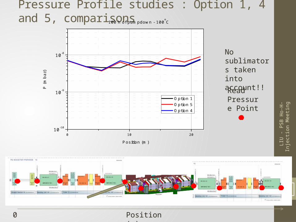
Pressure Profile studies : Option 1, 4 and 5, comparisons
10
Position (m)
Read Pressure Point
0
No sublimators taken into account!!
0 10 2010-10
10-9
10-8
P (m
bar)
Position (m)
Option 1 Option 5 Option 4
100 h of pumpdown - 100C
LIU
- PS
B H
o-H
- Inj
ectio
n M
eetin
g
Intervention probability• Option 1: high risk for the foil integrity and foil mechanical
assembly, high risk for MTV mechanical assembly (high intervention dose).
• Option 5: same as option 1, more stainless steel surface and dumps and we lose the dump conditioning every time the system is vented to air equal longer time to achieve nominal beam (2.5h+less personal dose for pumping and leak detection).
• Option 4: same as for option 1. More stainless steel surface, but not critical. More space in injector zone (less personal dose for pumping and leak detection) and no loss of the dump conditioning.
11
LIU
- PS
B H
o-H
- Inj
ectio
n M
eetin
g
Conclusions
• The displacement of these sector valves would allow for a safer intervention scenarios.• The conditioning time has been evaluated for the worst case scenario of a SiC dump
with broken contact for its cooling.• In this scenario, the maximum temperature reached by the dump is around 240 ◦C,
while the surrounding chamber heats up to 105 ◦C.• Based on measured outgassing rates and excluding dynamic effects, we have
calculated that:• The venting to air of the dump has a limited effect on the pressure in the vacuum sector:
max a factor 2 higher for about 2.5 hours. • The impact on the duty time should be limited to 2 to 3 hours max.
• Other materials than SiC would have a much higher effect on the pressure ( e.g. graphite, more than a factor of 10 higher); as a consequence they should not be vented;
• The position of the valve can be changed from option 4 to option 5 whenever dump materials equivalent to SiC are chosen. No change to option 5 is possible for other materials or sliced SiC dump.
• Anyhow, option 5 will lead to a longer intervention time (at least 2.5 hours) than option 4. 12
LIU
- PS
B H
o-H
- Inj
ectio
n M
eetin
g
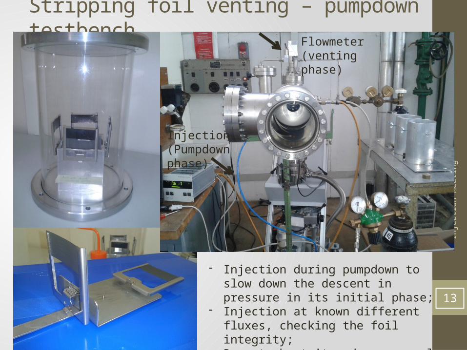
Stripping foil venting – pumpdown testbench
13
- Injection during pumpdown to slow down the descent in pressure in its initial phase;
- Injection at known different fluxes, checking the foil integrity;
- Report about it under approval;
Flowmeter (venting phase)
Injection(Pumpdown phase)