PSB 2342-600 Bicarbonator - Clemco Industries Corpclemcoindustries.com/images/pdfs/25131m.pdf ·...
22
OWNER’S MANUAL © 2012 CLEMCO INDUSTRIES CORP. Stock No.: 25131 Manual No.: 2335-0907 Date of Issue: Dec. 2009, Rev. A, 08/12 NOTICE TO PURCHASERS AND USERS OF OUR PRODUCTS AND THIS INFORMATIONAL MATERIAL Clemco proudly provides products for the abrasive blast industry and is confident that industry professionals will use their knowledge and expertise for the safe and efficient use of these products. The products described in this material, and the information relating to these products, are intended for knowledgeable, experienced users. No representation is intended or made as to: the suitability of the products described here for any purpose or application, or to the efficiency, production rate, or useful life of these products. All estimates regarding production rates or finishes are the responsibility of the user and must be derived solely from the user’s experience and expertise, not from information contained in this material. It is possible that the products described in this material may be combined with other products by the user for purposes determined solely by the user. No representations are intended or made as to the suitability of or engineering balance of or compliance with regulations or standard practice of any such combination of products or components the user may employ. Abrasive blast equipment is only one component of an abrasive blasting job. Other products, such as air compressors, air filters and receivers, abrasives, parts handling or other equipment, even if offered by Clemco, may have been manufactured or supplied by others. The information Clemco provides is intended to support the products Clemco manufactures. Users must contact each manufacturer and supplier of products used in the blast job for warnings, information, training, and instruction relating to the proper and safe use of their equipment. PSB 2342-600 Bicarbonator Bicarbonate of Soda Pressure Blast Cabinets Clemco Industries Corp. One Cable Car Drive Washington, MO 63090 Phone: (636) 239-4300 Fax (800) 726-7559 Email: [email protected] www.clemcoindustries.com
Transcript of PSB 2342-600 Bicarbonator - Clemco Industries Corpclemcoindustries.com/images/pdfs/25131m.pdf ·...

OWNER’S MANUAL© 2012 CLEMCO INDUSTRIES CORP. Stock No.: 25131 Manual No.: 2335-0907 Date of Issue: Dec. 2009, Rev. A, 08/12
NOTICE TO PURCHASERS AND USERS OF OUR PRODUCTS AND THIS INFORMATIONAL MATERIAL
Clemco proudly provides products for the abrasive blast industry and is confident that industry professionals will use their knowledge and expertise for the safe and efficient use of these products. The products described in this material, and the information relating to these products, are intended for knowledgeable, experienced users. No representation is intended or made as to: the suitability of the products described here for any purpose or application, or to the efficiency, production rate, or useful life of these products. All estimates regarding production rates or finishes are the responsibility of the user and must be derived solely from the user’s experience and expertise, not from information contained in this material. It is possible that the products described in this material may be combined with other products by the user for purposes determined solely by the user. No representations are intended or made as to the suitability of or engineering balance of or compliance with regulations or standard practice of any such combination of products or components the user may employ. Abrasive blast equipment is only one component of an abrasive blasting job. Other products, such as air compressors, air filters and receivers, abrasives, parts handling or other equipment, even if offered by Clemco, may have been manufactured or supplied by others. The information Clemco provides is intended to support the products Clemco manufactures. Users must contact each manufacturer and supplier of products used in the blast job for warnings, information, training, and instruction relating to the proper and safe use of their equipment.
PSB 2342-600 BicarbonatorBicarbonate of Soda
Pressure Blast Cabinets
Clemco Industries Corp. One Cable Car Drive Washington, MO 63090 Phone: (636) 239-4300 Fax (800) 726-7559
Email: [email protected] www.clemcoindustries.com

PSB 2342-600 BICARBONATOR SODA BLAST CABINET Page 1
© 2012 CLEMCO INDUSTRIES CORP. www.clemcoindustries.com Manual No. 25131, Rev. A
1.0 INTRODUCTION 1.1 Scope of Manual
1.1.1 These instructions cover set-up, operation, maintenance, troubleshooting, optional accessories, and replacement parts for PSB 2342-600 bicarbonate of soda pressure blast cabinets. 1.1.2 These instructions also contain important information required for safe operation of the cabinet. Before using this equipment, all personnel associated with the blast cabinet operation must read this entire manual, and all accessory manuals to become familiar with the operation, parts and terminology. 1.2 Safety Alerts
1.2.1 Clemco uses safety alert signal words, based on ANSI Z535.4-1998, to alert the user of a potentially hazardous situation that may be encountered while operating this equipment. ANSI's definitions of the signal words are as follows:
This is the safety alert symbol. It is used to alert the user of this equipment of potential personal injury hazards.
Obey all safety messages that follow this symbol to avoid possible injury or death.
CAUTION Caution used without the safety alert symbol indicates a potentially hazardous situation which, if not avoided, may result in property damage.
CAUTION Caution indicates a potentially hazardous situation which, if not avoided, may result in minor or moderate injury.
WARNING Warning indicates a potentially hazardous situation which, if not avoided, could result in death or serious injury.
DANGER Danger indicates an imminently hazardous situation which, if not avoided, will result in death or serious injury.
1.3 General Description
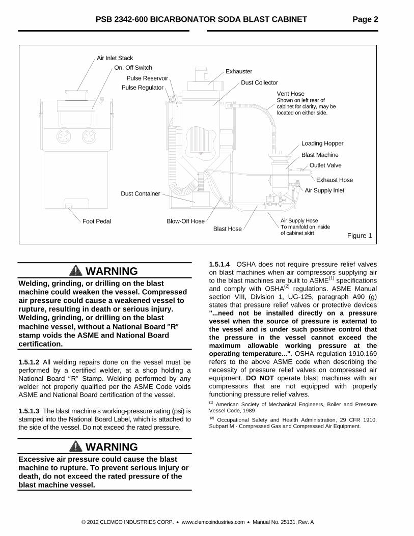
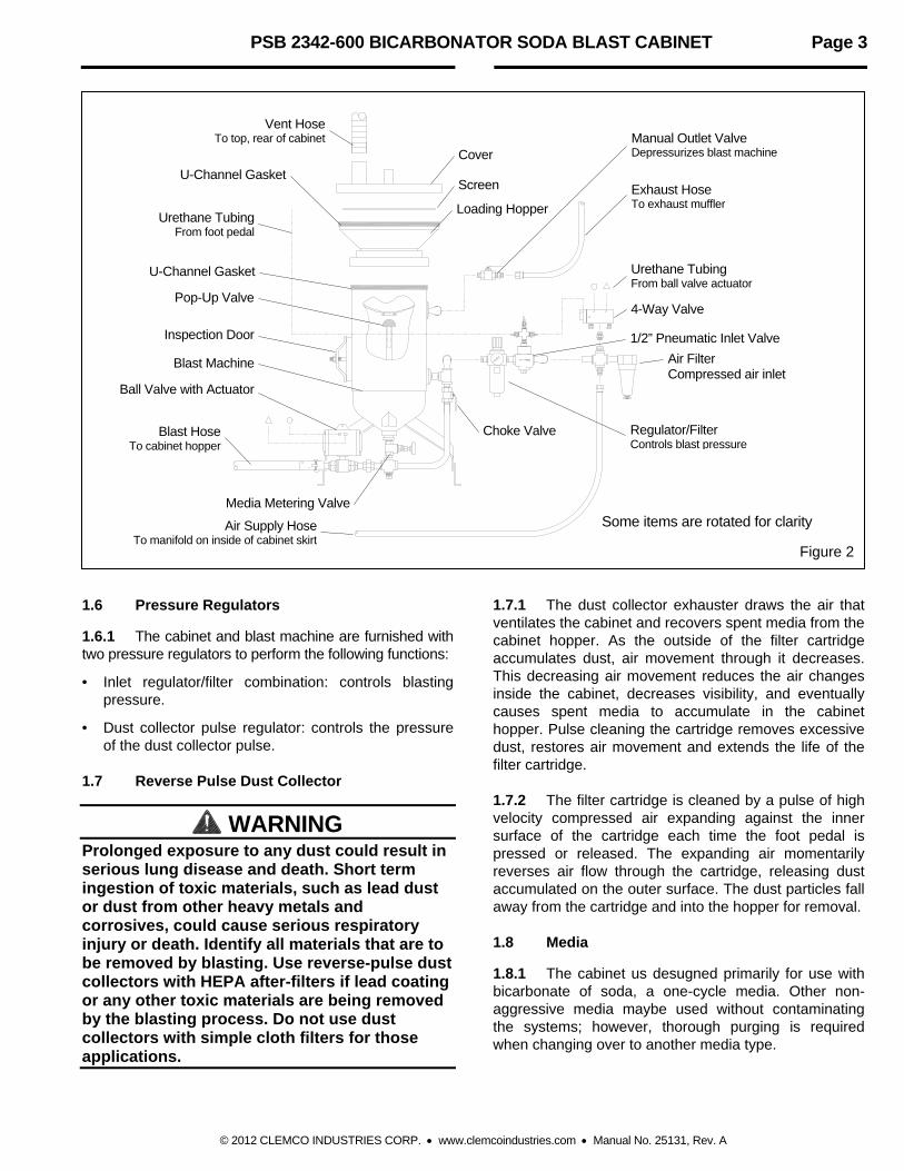
1.3.1 Aerolyte soda cabinets enclose the blasting environment to provide efficient blast cleaning while maintaining a clean surrounding work area. Production rates are influenced by size of nozzle, compressor output, working pressure, type and size of media, angle and distance of the nozzle from the blast surface. Aerolyte PSB 2343 cabinet consists of three major components: 1. Cabinet Enclosure 2. Dust Collector, 600 cfm 3. Blast Machine and Loading Hopper Refer to Figure 1 for the general arrangement and callouts of the major parts, and to Figure 2 for identification of blast machine parts. 1.4 Theory of Operation
1.4.1 When the air supply is ON, and the cabinet doors are closed, the cabinet is ready for operation. Depressing the foot pedal begins the blasting process that propels the media through the blast hose and out the nozzle. After striking the surface of the object being cleaned, the media particals, along with fines, dust, and by-products generated by the process, fall through the mesh work table into the cabinet hopper. These particles are pulled to the dust collector, where a filter cartridge traps the particles, and discharges clean air. When the foot pedal is released, blasting stops. The machine remains under pressure until manually depressurized. 1.5 Blast Machine and Controls Components of the machine are shown on the blast machine assembly drawings. They include the blast machine, manual pressurization valve, foot-pedal blasting controls, and pressure regulator/air filter. 1.5.1 Blast Machine
1.5.1.1 The blast machine pressure vessel is manufactured to American Society of Mechanical Engineers (ASME) standards, as described in Section VII, Div. 1, and carries a National Board certification. It is the owner’s responsibility to maintain the integrity of the vessel as may be required by regulations in some states. Regulations may include regular inspection and hydrostatic testing as described in National Board Inspection Code and Jurisdictional Regulations and/or Laws.
PSB 2342-600 BICARBONATOR SODA BLAST CABINET Page 2
© 2012 CLEMCO INDUSTRIES CORP. www.clemcoindustries.com Manual No. 25131, Rev. A
Figure 1
WARNING Welding, grinding, or drilling on the blast machine could weaken the vessel. Compressed air pressure could cause a weakened vessel to rupture, resulting in death or serious injury. Welding, grinding, or drilling on the blast machine vessel, without a National Board R stamp voids the ASME and National Board certification. 1.5.1.2 All welding repairs done on the vessel must be performed by a certified welder, at a shop holding a National Board R Stamp. Welding performed by any welder not properly qualified per the ASME Code voids ASME and National Board certification of the vessel. 1.5.1.3 The blast machine’s working-pressure rating (psi) is stamped into the National Board Label, which is attached to the side of the vessel. Do not exceed the rated pressure.
WARNING Excessive air pressure could cause the blast machine to rupture. To prevent serious injury or death, do not exceed the rated pressure of the blast machine vessel.
1.5.1.4 OSHA does not require pressure relief valves on blast machines when air compressors supplying air to the blast machines are built to ASME(1) specifications and comply with OSHA(2) regulations. ASME Manual section VIII, Division 1, UG-125, paragraph A90 (g) states that pressure relief valves or protective devices "...need not be installed directly on a pressure vessel when the source of pressure is external to the vessel and is under such positive control that the pressure in the vessel cannot exceed the maximum allowable working pressure at the operating temperature...". OSHA regulation 1910.169 refers to the above ASME code when describing the necessity of pressure relief valves on compressed air equipment. DO NOT operate blast machines with air compressors that are not equipped with properly functioning pressure relief valves. (1) American Society of Mechanical Engineers, Boiler and Pressure Vessel Code, 1989 (2) Occupational Safety and Health Administration, 29 CFR 1910, Subpart M - Compressed Gas and Compressed Air Equipment.
Exhauster On, Off Switch
Vent Hose Shown on left rear of cabinet for clarity, may be located on either side.
Loading Hopper
Exhaust Hose
Blast Machine
Blast HoseAir Supply Hose To manifold on inside of cabinet skirt
Foot Pedal
Pulse Reservoir
Pulse Regulator Dust Collector
Dust Container
Outlet Valve
Air Supply Inlet
Blow-Off Hose
Air Inlet Stack
PSB 2342-600 BICARBONATOR SODA BLAST CABINET Page 3
© 2012 CLEMCO INDUSTRIES CORP. www.clemcoindustries.com Manual No. 25131, Rev. A
Figure 2 1.6 Pressure Regulators
1.6.1 The cabinet and blast machine are furnished with two pressure regulators to perform the following functions:
• Inlet regulator/filter combination: controls blasting pressure.
• Dust collector pulse regulator: controls the pressure of the dust collector pulse.
1.7 Reverse Pulse Dust Collector
WARNING Prolonged exposure to any dust could result in serious lung disease and death. Short term ingestion of toxic materials, such as lead dust or dust from other heavy metals and corrosives, could cause serious respiratory injury or death. Identify all materials that are to be removed by blasting. Use reverse-pulse dust collectors with HEPA after-filters if lead coating or any other toxic materials are being removed by the blasting process. Do not use dust collectors with simple cloth filters for those applications.
1.7.1 The dust collector exhauster draws the air that ventilates the cabinet and recovers spent media from the cabinet hopper. As the outside of the filter cartridge accumulates dust, air movement through it decreases. This decreasing air movement reduces the air changes inside the cabinet, decreases visibility, and eventually causes spent media to accumulate in the cabinet hopper. Pulse cleaning the cartridge removes excessive dust, restores air movement and extends the life of the filter cartridge. 1.7.2 The filter cartridge is cleaned by a pulse of high velocity compressed air expanding against the inner surface of the cartridge each time the foot pedal is pressed or released. The expanding air momentarily reverses air flow through the cartridge, releasing dust accumulated on the outer surface. The dust particles fall away from the cartridge and into the hopper for removal. 1.8 Media
1.8.1 The cabinet us desugned primarily for use with bicarbonate of soda, a one-cycle media. Other non-aggressive media maybe used without contaminating the systems; however, thorough purging is required when changing over to another media type.
Vent Hose To top, rear of cabinet
Loading Hopper
Exhaust Hose To exhaust muffler
Urethane Tubing From ball valve actuator
Regulator/Filter Controls blast pressure
Blast Hose To cabinet hopper
Air Supply Hose To manifold on inside of cabinet skirt
4-Way Valve
Manual Outlet Valve Depressurizes blast machine
Pop-Up Valve
Urethane Tubing From foot pedal
Ball Valve with Actuator
Media Metering Valve
Cover
Air Filter Compressed air inlet
Choke Valve
Some items are rotated for clarity
Screen
1/2” Pneumatic Inlet Valve
U-Channel Gasket
U-Channel Gasket
Blast Machine
Inspection Door
PSB 2342-600 BICARBONATOR SODA BLAST CABINET Page 4
© 2012 CLEMCO INDUSTRIES CORP. www.clemcoindustries.com Manual No. 25131, Rev. A
1.9 Compressed Air Requirements
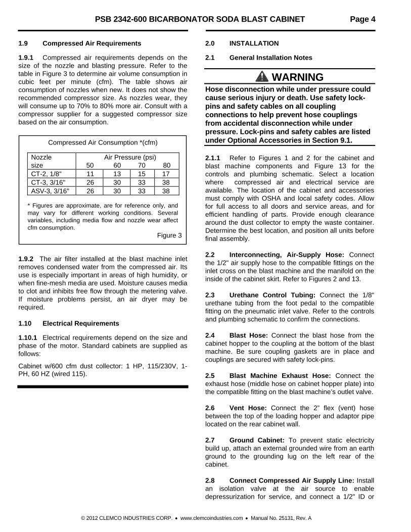
1.9.1 Compressed air requirements depends on the size of the nozzle and blasting pressure. Refer to the table in Figure 3 to determine air volume consumption in cubic feet per minute (cfm). The table shows air consumption of nozzles when new. It does not show the recommended compressor size. As nozzles wear, they will consume up to 70% to 80% more air. Consult with a compressor supplier for a suggested compressor size based on the air consumption.
Compressed Air Consumption *(cfm)
Nozzle Air Pressure (psi) size 50 60 70 80 CT-2, 1/8" 11 13 15 17 CT-3, 3/16" 26 30 33 38 ASV-3, 3/16" 26 30 33 38
* Figures are approximate, are for reference only, and may vary for different working conditions. Several variables, including media flow and nozzle wear affect cfm consumption.
Figure 3 1.9.2 The air filter installed at the blast machine inlet removes condensed water from the compressed air. Its use is especially important in areas of high humidity, or when fine-mesh media are used. Moisture causes media to clot and inhibits free flow through the metering valve. If moisture problems persist, an air dryer may be required. 1.10 Electrical Requirements
1.10.1 Electrical requirements depend on the size and phase of the motor. Standard cabinets are supplied as follows:
Cabinet w/600 cfm dust collector: 1 HP, 115/230V, 1-PH, 60 HZ (wired 115).
2.0 INSTALLATION
2.1 General Installation Notes
WARNING Hose disconnection while under pressure could cause serious injury or death. Use safety lock-pins and safety cables on all coupling connections to help prevent hose couplings from accidental disconnection while under pressure. Lock-pins and safety cables are listed under Optional Accessories in Section 9.1. 2.1.1 Refer to Figures 1 and 2 for the cabinet and blast machine components and Figure 13 for the controls and plumbing schematic. Select a location where compressed air and electrical service are available. The location of the cabinet and accessories must comply with OSHA and local safety codes. Allow for full access to all doors and service areas, and for efficient handling of parts. Provide enough clearance around the dust collector to empty the waste container. Determine the best location, and position all units before final assembly. 2.2 Interconnecting, Air-Supply Hose: Connect the 1/2" air supply hose to the compatible fittings on the inlet cross on the blast machine and the manifold on the inside of the cabinet skirt. Refer to Figures 2 and 13. 2.3 Urethane Control Tubing: Connect the 1/8" urethane tubing from the foot pedal to the compatible fitting on the pneumatic inlet valve. Refer to the controls and plumbing schematic to confirm the connections. 2.4 Blast Hose: Connect the blast hose from the cabinet hopper to the coupling at the bottom of the blast machine. Be sure coupling gaskets are in place and couplings are secured with safety lock-pins. 2.5 Blast Machine Exhaust Hose: Connect the exhaust hose (middle hose on cabinet hopper plate) into the compatible fitting on the blast machine’s outlet valve. 2.6 Vent Hose: Connect the 2” flex (vent) hose between the top of the loading hopper and adaptor pipe located on the rear cabinet wall. 2.7 Ground Cabinet: To prevent static electricity build up, attach an external grounded wire from an earth ground to the grounding lug on the left rear of the cabinet. 2.8 Connect Compressed Air Supply Line: Install an isolation valve at the air source to enable depressurization for service, and connect a 1/2" ID or

PSB 2342-600 BICARBONATOR SODA BLAST CABINET Page 5
© 2012 CLEMCO INDUSTRIES CORP. www.clemcoindustries.com Manual No. 25131, Rev. A
larger air line from the air source to the blast machine inlet. A smaller diameter hose may reduce blasting efficiency.
WARNING If twist-on type air hose couplings are used, they must be secured by safety pins or wires to prevent accidental disconnection while under pressure. Hose disconnection while under pressure could cause serious injury. 2.9 Plug the U-ground plug power cord into a 115-volt outlet.
WARNING Do not use electrical adaptors that eliminate the ground prong on 115 volt plugs. Doing so can cause electric shock and equipment damage. 2.10 Check Motor Rotation: Observe the subsequent warning and check the rotation of the motor. To check, jog the starter (momentarily turn switch on and off). This will cause the motor to rotate slowly. Look through the slots in the fan housing on top of the motor where rotation of the fan can easily be observed. Do not look into the exhauster outlet. Proper rotation is indicated by the arrow on the exhauster housing. The motor should rotate toward the exhauster outlet.
WARNING Do not look into the exhauster outlet while the paddle wheel is turning. Injury to the eye or face could occur from objects being ejected from the exhauster. 2.11 Foot Pedal: Position the foot pedal on the floor at the front of the cabinet.
3.0 Initial Start-Up
3.1 Make sure all hose connections are secure. 3.2 Turn on the lights and exhauster. The on/off switch located on the light shield performs both functions. Verify the operation of the lights and exhauster. 3.3 Close the blast machine’s outlet valve. The valve is closed when the handle is perpendicular to the valve.
3.4 Slowly open the air supply valve to pressurize the air supply line. Listen for leaks. If any are noted, shut off the air supply, and identify and correct the leak(s). 3.5 Adjust the dust collector pulse regulator located on the pulse manifold to 60 psi. 3.6 Depress and release the foot pedal. The blast machine pressurizes and blasting begins when the pedal is depressed. Blasting stops but the machine remains pressurized when the pedal is released. The dust collector should pulse once when the pedal is depressed and once when it is released. 3.7 Adjust the inlet pressure regulator per Section 5.1. 3.8 Check for leaks in the plumbing and hose connections. 3.9 When certain the cabinet is operational, depressurize the machine by opening the manual outlet valve, and load media per Section 4.2. 3.10 Set pulse pressure to 0 psi until the cartridge is seasoned per Section 7.12.
4.0 OPERATION 4.1 Season Filter Cartridge
CAUTION Do not pulse new dust collectors and cartridges until the cartridge is seasoned. See Section 7.12. Premature pulsing decreases the efficiency of collector and cartridge life. 4.2 Loading Media NOTE: Media should be well screened. Use only media specifically manufactured for blast cleaning. 4.2.1 Media Capacity: Media capacity is approximately 0.5 cubic ft. 4.2.2 Do not load new media into the blast machine before emptying the dust collector’s dust container.
CAUTION Failure to empty the dust collector before refilling the blast machine will result in overfilling the dust collector, and as a result, make it difficult to empty the dust container.

PSB 2342-600 BICARBONATOR SODA BLAST CABINET Page 6
© 2012 CLEMCO INDUSTRIES CORP. www.clemcoindustries.com Manual No. 25131, Rev. A
4.2.3 Remove the loading hopper cover, and load media by pouring it through the inlet screen and into the blast machine. Do not let media cover the pop-up valve. Overfilling the blast machine could result in overfilling the dust collector’s dust container. 4.3 Unloading Media
4.3.1 Empty the machine of all media when shutting down for the day. This will eliminate trouble from moist media when starting a new day's blasting. One way to avoid having to empty the machine is to load only as much media as will be used during the work period. To empty the machine, do the following. 4.3.2 Close the choke valve, then open the media metering valve by turning the knob fully counterclockwise. Counting the turns on the metering handle makes it easier to return the valve to the preset position. 4.3.3 Close the doors, hold the nozzle securely, and press the foot pedal. 4.3.4 When the machine is empty, release the foot pedal, return the choke valve to the full open position, and readjust the metering valve. 4.4 Loading and Unloading Parts
WARNING Use solid fixturing to hold heavy parts in place. Do not remove lift equipment until the part is adequately supported to prevent movement. Moving heavy, unsupported parts may cause them to shift or topple, and cause severe injury. This is especially important when using a turntable. 4.4.1 Load and unload parts through either door. 4.4.2 Parts must be free of oil, water, grease, or other contaminants that will cause media to clump, or clog the dust collector filter. 4.4.3 Close door. Be certain door is sealed securely, or door interlock system will prevent the machine from working.
4.5 Blasting Operation
CAUTION Always close cabinet doors and loading
hopper cover before blasting. Keep all doors closed during blasting.
Always wear blast gloves. Avoid pointing the blast nozzle toward the
view window. Use the blow-off nozzle to blow media off
parts before opening doors. After blasting, keep doors closed and
exhauster ON until the cabinet is clear of all airborne dust.
Stop blasting immediately if dust leaks are detected.
4.5.1 Slowly pressurize the air supply hose to the blast machine. 4.5.2 Turn on the lights and exhauster. 4.5.3 Load parts. 4.5.4 Close door. Be certain doors are sealed securely, or door interlock system will prevent blasting. 4.5.5 Close the manual outlet valve. 4.5.6 Firmly grasp the nozzle and apply pressure to the foot pedal. Blasting will begin immediately. 4.5.7 Adjust the blast pressure per Section 5.1. NOTE: Whenever possible avoid holding small parts that will require blasting into the glove.
WARNING Shut down the cabinet immediately if dust discharges from the collector. Make sure the filter is correctly seated and not damaged. Prolonged breathing of any dust could result in serious lung disease. Short term ingestion of toxic dust such as lead, poses an immediate danger to health. Toxicity and health risk vary with dust generated by blasting. Identify all material being removed by blasting, and obtain a material safety data sheet for the media. 4.5.8 When blasting very small parts, place a screen over the grate to prevent parts from falling into the hopper. If an object should fall through the grate, stop blasting immediately and retrieve it.
PSB 2342-600 BICARBONATOR SODA BLAST CABINET Page 7
© 2012 CLEMCO INDUSTRIES CORP. www.clemcoindustries.com Manual No. 25131, Rev. A
4.6 Blasting Technique
4.6.1 Blasting technique is similar to spray painting technique. Smooth continuous strokes are usually most effective. The distance from the part affects size of blast pattern. Under normal conditions, hold the gun approximately 6" from the surface of the part. 4.7 Stop Blasting
4.7.1 To stop blasting, remove pressure on the foot pedal. Releasing the foot pedal closes the inlet valve and ball valve with actuator. The blast machine remains pressurized until the manual outlet valve is opened. NOTE: If there are small leaks in the plumbing, the blast machine may lose pressure. The machine will re-pressurize to full pressure as soon as the foot pedal is pressed. 4.7.2 Use the blow-off nozzle to blow media off cleaned parts. Allow the exhauster to clear the cabinet of airborne dust before opening the door.
CAUTION Do not use the blow-off nozzle to clean accumulated media from the ClearView™ glass partition or view window. Doing so will force dust laden air out the inlet stack. 4.7.3 Unload parts. 4.8 Depressurizing the Blast Machine
4.8.1 When ready to shut-down or refill the blast machine, remove pressure on the foot pedal, then open the manual outlet valve. Opening the outlet valve depressurizes the blast machine through the exhaust hose and into the cabinet hopper. 4.8.2 Refill the blast machine as needed per Section 4.2. 4.9 Shut-Down
4.9.1 Empty the blast machine per Section 4.3. 4.9.2 Depressurize the blast machine per Section 4.8. 4.9.3 Switch off the lights and exhauster. 4.9.4 Empty the dust container per Section 6.3. 4.9.5 Shut-down the compressor or air supply, and bleed the air supply line.
5.0 ADJUSTMENTS NOTE: Pressure regulators furnished on the machine have locking adjustment knobs. Pull the knob out to make the adjustment, push the knob in to lock it and maintain the setting. 5.1 Inlet Regulator (Blast Pressure)
5.1.1 Blasting pressure (the pressure coming out the nozzle), is adjusted at the blast machine’s combination regulator/filter. Air does not pass through the regulator unless the foot pedal is pressed. Two people make the initial adjustment easier. Once pressure is set, it seldom requires readjustment. If the application requires frequent air pressure adjustments, swap the location of the pneumatic inlet valve and regulator. This enables pressure adjustment before pressing the foot pedal. 5.1.2 Blast pressure may be regulated between a low of 5 psi to a maximum of 125 psi. Most bicarbonate of soda blasting is done between 30 and 60 psi. 5.2 Pulse Pressure
CAUTION Do not pulse new dust collectors or new cartridges until the cartridge is seasoned, as explained in Section 7.12. Premature pulsing decreases the efficiency of collector and cartridge life. 5.2.1 After the cartridge is seasoned, adjust pulse pressure using the regulator mounted on the pulse reservoir. Begin pulse at 60 psi. 5.2.2 As the filter cartridge cakes with dust, it may be necessary to pulse during blasting per Section 6.5. 5.2.3 When pulsing alone does not adequately clean the cartridge, increase pulse pressure by 5 to 10 psi increments to a maximum of 100 psi. As dust cakes on the cartridge, the differential pressure increases. Using a manometer to measure the differential pressure is a good way to tell if the cartridge is heavily caked. 5.2.4 Replace the cartridge per Section 7.11, when the frequency of the pulse and maximum pulse pressure no longer sufficiently clean the cartridge to provide good visibility. An excessively dirty cartridge will eventually cause spent media to accumulate in the cabinet hopper and may create positive pressure inside the cabinet, resulting in dust leaks.

PSB 2342-600 BICARBONATOR SODA BLAST CABINET Page 8
© 2012 CLEMCO INDUSTRIES CORP. www.clemcoindustries.com Manual No. 25131, Rev. A
5.3 Media Metering (Abrasive Flow)
5.3.1 Adjust media flow by turning the knob on the metering valve. The valve is closed when the knob is fully clockwise. To adjust, close the valve and slowly turn the knob counterclockwise to increase media flow. Use as little media as possible while maintaining the best cleaning rate. Generally, with the correct mixture, media should barely be seen as light discoloration as it exits the nozzle. 5.4 Door Interlocks, Figure 4.
WARNING Never attempt to override the interlock system. Doing so could result in injury from unexpected blasting. 5.4.1 The door interlocks disable the blasting control circuit when the doors are open. To enable blasting, the door interlock switch must be engaged when the doors are closed. The interlocks are set at the factory and do not usually require field adjustment unless parts are replaced. When adjustment is required, proceed as follows. 5.4.2 Close cabinet doors. 5.4.3 Loosen the actuator bracket screws and adjusting screw nut. Move the actuator adjusting bracket up or down, and the adjusting screw sideways, to center the adjusting screw on the over-travel stop. Tighten the bracket screws.
Figure 4
5.4.4 Turn the adjusting screw in or out as required to engage the switch without applying excessive pressure on it. Tighten the adjusting screw nuts. 5.4.5 Test the operation with the doors open and then again closed. Point the nozzle away from the door during the tests, and open the door onlyenough to disengage the interlock switch. The interlocks should stop the blasting when the doors are opened, and permit blasting when the doors are closed. NOTE: Negative pressure inside the cabinet may cause the doors to flex inward. Tests should be performed with the exhauster on.
6.0 PREVENTIVE MAINTENANCE
WARNING Failure to wear approved respirators and eye protection when servicing dust-laden areas of the cabinet and dust collector, and when emptying the dust collector could result in serious eye irritation and lung disease or death. Toxicity and health risk vary with type of media and dust generated by blasting. The respirator must be approved for the type of dust generated. Identify all material being removed by blasting, and obtain a material safety data sheet for the blast media.
NOTE: To avoid unscheduled downtime, establish a weekly inspection schedule. Inspect all parts subjected to media contact including: nozzle, media hose, flex hose, and all items covered in this section. 6.1 View Window and ClearView™ Air Channel
6.1.1 While the exhauster is running, clean the view window and glass air channel partition with a soft bristle brush. The blow-off nozzle may be used to blow-off the backside (work chamber side) of the partition, but do not direct air into the flow channel. Doing so will blow dust laden air out the inlet stack. The view window and partition is easily removed for thorough cleaning or replacement. To remove the partition, loosen the side and top plastic retaining nuts, and slide the partition from the side retainers. When replacing the partition, tighten the nuts only enough to hold the partition; it takes very little pressure to hold it in place. Refer to Section 7.3 to service the view window. Cabinet Door
Detent Sleeve
Over-travel Stop
Adjusting Screw Nut Loosen, and move sideways to center the adjusting screw on the over-travel stop.
Actuator Adjusting Bracket Loosen the bracket screws, and move the bracket up or down to center the adjusting screw on the over-travel stop.
Adjusting Screw Adjust the screw to depress the valve stem when door is closed.
Bracket Screws
PSB 2342-600 BICARBONATOR SODA BLAST CABINET Page 9
© 2012 CLEMCO INDUSTRIES CORP. www.clemcoindustries.com Manual No. 25131, Rev. A
6.2 Compressed-Air Filters
6.2.1 The cabinet’s blast machine is equipped with an air filter and a combination pressure regulator/air filter. The first inlet filter has a manual drain that must be opened periodically to drain accumulated water. The regulator/filter automatically drains when moisture fills the bowl to a certain level. Moist air inhibits the flow of media. If moisture problems persist, an air dryer may be required. 6.3 Dust Collector Dust Container
6.3.1 Empty the dust container before refilling the blast machine. 6.3.2 Turn off the exhauster and release the dust container from the cover. The cover's flexible inlet hose allows easy removal. Remove the container and dump the contents into a suitable disposal container. Replace the container being certain the cover is in place. NOTE: Blasting media is usually non-toxic, however, some materials being removed by the process may be toxic. Obtain MSDS sheets for the media and identify all material removed by the blast process. Check with proper authorities for disposal restrictions. 6.4 Pulse Reservoir
6.4.1 Open the petcock to drain water from the pulse reservoir before and after each use. See Figure 8 for the location of the drain petcock. 6.5 Routine Additional Cartridge Pulsing
6.5.1 The cartridge is pulsed each time the foot pedal is pressed or released. Additional pulsing should be performed dailey per the following instructions, or more often under dusty conditions, to prevent clogging of the cartridge. 6.5.2 Turn off exhauster. 6.5.3 Hold the blast nozzle and rapidly press and release the foot pedal three times. Activating the foot pedal more than three times may cause dust to escape from the enclosure. 6.5.4 Start the exhauster and let it run for 10 seconds or until all airborne dust is cleared from the cabinet. 6.5.5 Repeat the process several times. 6.5.6 Refer to Section 7.10 for cartridge cleaning.
6.6 Monthly inspection
6.6.1 Before blasting and with air off.
Inspect the blast hose for wear; look for soft spots. Soft spots mean the hose is worn thin. Replace the blast hose before the tube wears into the fabric plies.
Remove the nozzle for inspection. Replace if worn or cracked.
Inspect and clean the compressed air filter and bowl.
Inspect pop-up valve and seal for wear. Refer to Sections 7.6 and 7.7.
6.6.2 During blasting
Inspect the blast machine for leaks. If leaks are found around the pop-up valve, inspection door, or pipe fittings leading into the machine, stop blasting and repair or replace worn parts. If leaks are allowed to continue, irreparable damage caused by abrasive erosion may occur to the blast machine.
Inspect the media metering valve for leaks. If leaks are found, stop blasting and repair.
Inspect blast hose, couplings, and nozzle holders for leaks. At the first sign of a leak, stop blasting and inspect all items for wear.
7.0 SERVICE MAINTENANCE
WARNING Failure to wear approved respirators and eye protection when servicing dust-laden areas of the cabinet and dust collector, and when emptying the dust collector could result in serious eye irritation and lung disease or death. Toxicity and health risk vary with type of media and dust generated by blasting. Identify all material being removed by blasting, and obtain a material safety data sheet for the blast media. 7.1 Gloves
7.1.1 Special static-dissipating gloves have been provided for operator comfort. It will be necessary to change gloves periodically as they wear. The first sign of deterioration may be excessive static shocks. 7.1.2 Gloves are held in place by metal bands on the inside of the cabinet. To replace, loosen the bands with a screwdriver, replace the gloves, and tighten the bands.
PSB 2342-600 BICARBONATOR SODA BLAST CABINET Page 10
© 2012 CLEMCO INDUSTRIES CORP. www.clemcoindustries.com Manual No. 25131, Rev. A
7.2 Nozzle
7.2.1 Replace the nozzle when its diameter has increased by 1/16", or sooner if pressure diminishes noticeably. Make sure the nozzle gasket is in place before screwing the nozzle into the nozzle holder. 7.3 View Window Replacement
WARNING Do not use plate glass for replacement view windows. Plate glass shatters on impact and could cause severe injury. Use only genuine replacement parts.
7.3.1 Lift the light shield up and remove the two window frame nuts located on the upper edge of the window frame, and swing the window frame open. Note: If the frame is to remain open, for cleaning or other reasons, remove it per Section 7.5. 7.3.2 Remove the old window. 7.3.3 Inspect the window frame gaskets, both on the window frame and on the cabinet. If either gasket is damaged, replace it per section 7.4. 7.3.4 Set the new window squarely over the window opening, making sure that all edges of the window are centered and overlapping the window gasket, and that the window is resting on the lower locators. 7.3.5 Swing the window frame into place and tighten the frame nuts. 7.4 Window Gasket Replacement, Figure 5
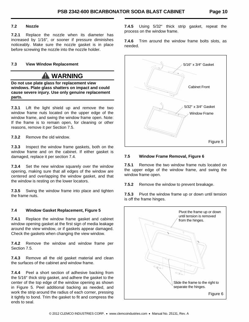
7.4.1 Replace the window frame gasket and cabinet window opening gasket at the first sign of media leakage around the view window, or if gaskets appear damaged. Check the gaskets when changing the view window. 7.4.2 Remove the window and window frame per Section 7.5. 7.4.3 Remove all the old gasket material and clean the surfaces of the cabinet and window frame. 7.4.4 Peel a short section of adhesive backing from the 5/16 thick strip gasket, and adhere the gasket to the center of the top edge of the window opening as shown in Figure 5. Peel additional backing as needed, and work the strip around the radius of each corner, pressing it tightly to bond. Trim the gasket to fit and compress the ends to seal.
7.4.5 Using 5/32 thick strip gasket, repeat the process on the window frame. 7.4.6 Trim around the window frame bolts slots, as needed.
Figure 5 7.5 Window Frame Removal, Figure 6
7.5.1 Remove the two window frame nuts located on the upper edge of the window frame, and swing the window frame open. 7.5.2 Remove the window to prevent breakage. 7.5.3 Pivot the window frame up or down until tension is off the frame hinges.
Figure 6
Cabinet Front
Window Frame
5/16 x 3/4 Gasket
5/32 x 3/4 Gasket
Pivot the frame up or down until tension is removed from the hinges.
Slide the frame to the right to separate the hinges.
PSB 2342-600 BICARBONATOR SODA BLAST CABINET Page 11
© 2012 CLEMCO INDUSTRIES CORP. www.clemcoindustries.com Manual No. 25131, Rev. A
7.5.4 Slide the frame to the right, to remove. The hinges separate as shown in Figure 6. 7.5.5 Replace the frame in reverse order. Align the top bolt holes with the bolts; slide the frame as necessary. 7.5.6 Set the window squarely over the window opening, ensuring that all edges of the window are centered and overlapping the window gasket, and resting on the lower locators. 7.5.7 Swing the window frame into place and tighten the frame nuts. 7.6 Replacing the Pop-up Valve, Figure 7
7.6.1 Empty the machine of media per Section 4.3. 7.6.2 Depressurize the blast machine, and lockout and tagout the compressed-air supply.
WARNING Failure to observe the following procedure before performing any maintenance could cause serious injury or death from the sudden release of compressed air. Depressurize the blast machine. Lockout and tagout the compressed air
supply. Bleed the air supply line to the blast
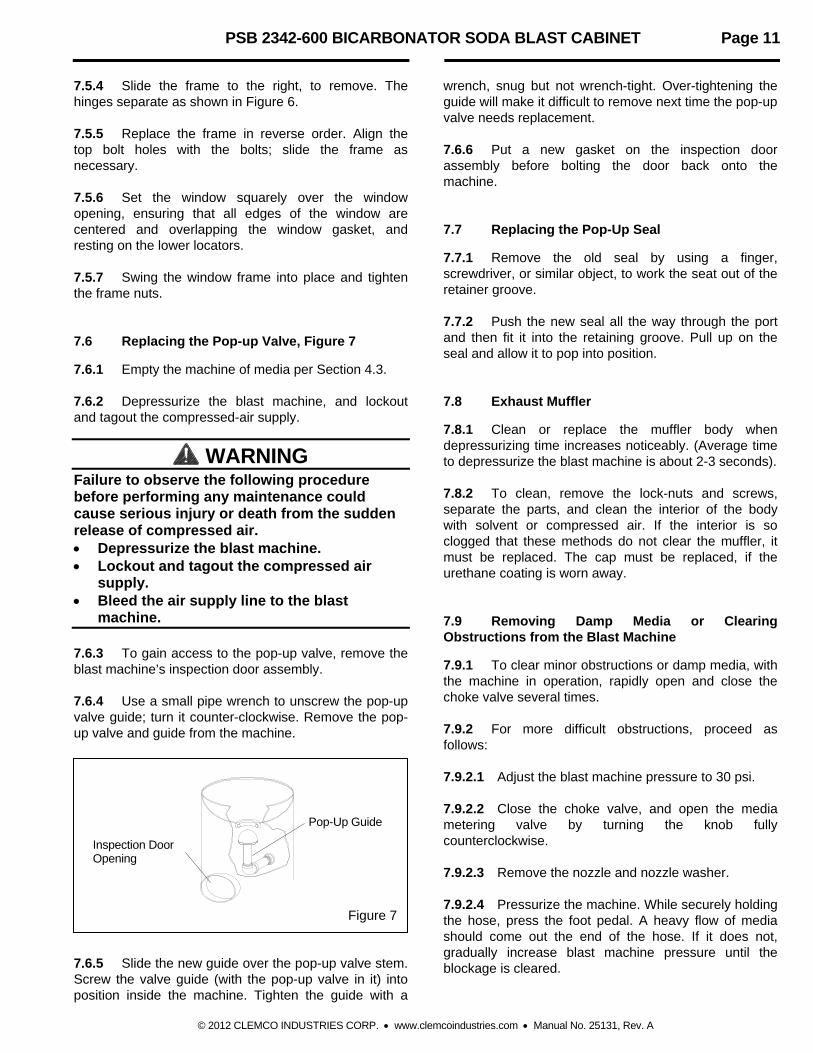
machine. 7.6.3 To gain access to the pop-up valve, remove the blast machine’s inspection door assembly. 7.6.4 Use a small pipe wrench to unscrew the pop-up valve guide; turn it counter-clockwise. Remove the pop-up valve and guide from the machine.
Figure 7 7.6.5 Slide the new guide over the pop-up valve stem. Screw the valve guide (with the pop-up valve in it) into position inside the machine. Tighten the guide with a
wrench, snug but not wrench-tight. Over-tightening the guide will make it difficult to remove next time the pop-up valve needs replacement. 7.6.6 Put a new gasket on the inspection door assembly before bolting the door back onto the machine. 7.7 Replacing the Pop-Up Seal
7.7.1 Remove the old seal by using a finger, screwdriver, or similar object, to work the seat out of the retainer groove. 7.7.2 Push the new seal all the way through the port and then fit it into the retaining groove. Pull up on the seal and allow it to pop into position. 7.8 Exhaust Muffler
7.8.1 Clean or replace the muffler body when depressurizing time increases noticeably. (Average time to depressurize the blast machine is about 2-3 seconds). 7.8.2 To clean, remove the lock-nuts and screws, separate the parts, and clean the interior of the body with solvent or compressed air. If the interior is so clogged that these methods do not clear the muffler, it must be replaced. The cap must be replaced, if the urethane coating is worn away. 7.9 Removing Damp Media or Clearing Obstructions from the Blast Machine
7.9.1 To clear minor obstructions or damp media, with the machine in operation, rapidly open and close the choke valve several times. 7.9.2 For more difficult obstructions, proceed as follows: 7.9.2.1 Adjust the blast machine pressure to 30 psi. 7.9.2.2 Close the choke valve, and open the media metering valve by turning the knob fully counterclockwise. 7.9.2.3 Remove the nozzle and nozzle washer. 7.9.2.4 Pressurize the machine. While securely holding the hose, press the foot pedal. A heavy flow of media should come out the end of the hose. If it does not, gradually increase blast machine pressure until the blockage is cleared.
Pop-Up Guide
Inspection Door Opening

PSB 2342-600 BICARBONATOR SODA BLAST CABINET Page 12
© 2012 CLEMCO INDUSTRIES CORP. www.clemcoindustries.com Manual No. 25131, Rev. A
7.9.2.5 Continue until the media is dry or the machine is empty. Release pressure on the foot pedal and depressurize the machine. 7.9.2.6 Thoroughly inspect the nozzle holder threads for wear before reconnecting the nozzle washer and nozzle. 7.9.2.7 Reset blast pressure. 7.10 Filter Cartridge Cleaning
CAUTION Use extreme caution when inserting cleaning tools inside the filter cartridge or when cleaning the outside surface. Do not use stiff bristle brushes or other materials that could abrade the filter media. Any surface abrasion or punctures will decrease filter performance and may require filter replacement.
WARNING Wear approved respirator and protective gear when cleaning the cartridge. Contain dust generated while cleaning, and collect it in a suitable disposal container. Check with proper authorities for disposal restrictions. 7.10.1 Pulse cartridges as described in Section 6.5. 7.10.2 Remove filter cartridge as explained in Section 7.11. 7.10.3 Dry Method Cleaning 7.10.3.1 Attach a 3/8-inch ID or larger wand to a compressed air line with pressure set at a maximum of 60 psi. 7.10.3.2 Insert the wand inside the filter cartridge and move the wand up and down following the pleats and covering the entire area of the cartridge. 7.10.3.3 Inspect the outside of the cartridge. If any contaminant is still visible on the outside (dust side) of the cartridge, clean the outside as follows.
CAUTION Do not blow air directly onto the outside surface of the cartridge. Blow air at a 45 degree angle to the pleated surface, and with the wand at a sufficient distance away from the surface to avoid damage to the filter media. 7.10.3.4 Use the wand to clean the outside surface. Make sure the wand is kept at 45 degrees and parallel to the pleats. Make sure the wand is at sufficient distance to avoid damaging the filter media. Remove contaminants from the outside surface without forcing it into the pores of the filter. 7.10.3.5 Repeat the cleaning of the inside of the filter one more time. 7.10.3.6 Reinstall the filter beginning at paragraph 7.11.5. 7.10.4 Wet Method Cleaning
CAUTION Do not use high pressure washers or water lines with pressure higher than 50 psi. Do not use oils solvents or harsh detergents. Damage to the filter could occur. 7.10.4.1 Place the filter in a 2-3% solution (about 4-oz. per gallon) of mild dish washing soap, and let cartridge soak for 10 minutes. 7.10.4.2 Remove the filter and rinse the inside with water from a garden hose not exceeding 50 psi. Be careful not to abrade the filter media. 7.10.4.3 Rinse the outside of the filter with the water stream at a 45 degree angle and parallel to the pleats. Thoroughly rinse all traces of detergent from both the inside and outside of the filter. 7.10.4.4 Allow the filter to dry 24 to 48 hours at 70 degrees F or higher. Do not dry the filter inside the collector with the fan. Filters must be completely dry before reuse. 7.10.4.5 Reinstall the filter beginning at paragraph 7.11.5.
PSB 2342-600 BICARBONATOR SODA BLAST CABINET Page 13
© 2012 CLEMCO INDUSTRIES CORP. www.clemcoindustries.com Manual No. 25131, Rev. A
7.11 Filter Cartridge Replacement, Figure 8
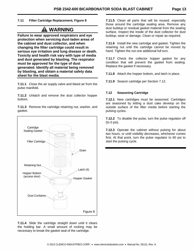
WARNING Failure to wear approved respirators and eye protection when servicing dust-laden areas of the cabinet and dust collector, and when changing the filter cartridge could result in serious eye irritation and lung disease or death. Toxicity and health risk vary with type of media and dust generated by blasting. The respirator must be approved for the type of dust generated. Identify all material being removed by blasting, and obtain a material safety data sheet for the blast media. 7.11.1 Close the air supply valve and bleed air from the pulse manifold. 7.11.2 Unlatch and remove the dust collector hopper bottom. 7.11.3 Remove the cartridge retaining nut, washer, and gasket.
Figure 8 7.11.4 Slide the cartridge straight down until it clears the holding bar. A small amount of rocking may be necessary to break the gasket seal of the cartridge.
7.11.5 Clean all parts that will be reused, especially those around the cartridge sealing area. Remove any dust buildup or residual gasket material from the sealing surface. Inspect the inside of the dust collector for dust buildup, wear or damage. Clean or repair as required. 7.11.6 Install the new cartridge and gasket. Tighten the retaining nut until the cartridge cannot be moved by hand. Tighten the nut one additional full turn. 7.11.7 Check the collector hopper gasket for any condition that will prevent the gasket from sealing. Replace the gasket if necessary. 7.11.8 Attach the hopper bottom, and latch in place. 7.11.9 Season cartridge per Section 7.12. 7.12 Seasoning Cartridge
7.12.1 New cartridges must be seasoned. Cartridges are seasoned by letting a dust cake develop on the outside surface of the filter media before starting the pulsing cycles. 7.12.2 To disable the pulse, turn the pulse regulator off (to 0 psi). 7.12.3 Operate the cabinet without pulsing for about two hours, or until visibility decreases, whichever comes first. At that point, turn the pulse regulator to 60 psi to start the pulsing cycle.
Cartridge Sealing Gasket
Filter Cartridge
Drain
Hopper Gasket
Dust Container
Retaining Nut
Latch (4) Hopper Bottom (access door)
PSB 2342-600 BICARBONATOR SODA BLAST CABINET Page 14
© 2012 CLEMCO INDUSTRIES CORP. www.clemcoindustries.com Manual No. 25131, Rev. A
8.0 TROUBLESHOOTING
WARNING To avoid serious injury, observe the following when troubleshooting. Turn off the air, and lockout and tagout the
air supply. If checking the controls requires air, always
enlist the aid of another person to: Hold the nozzle securely. Operate the foot pedal. Never bypass the foot pedal or wedge it in
the operating position. Never override the door interlock system.
8.1 Poor Visibility
8.1.1 Dirty filter cartridge. Refer to Sections 5.2 and 6.5 for pulse pressure and additional pulsing. 8.1.2 Motor rotating backwards. The motor should rotate as indicated by the arrow on the housing. If it does not rotate in the proper direction, lockout and tagout power, and switch the motor leads as shown on the motor plate. 8.1.3 Hole worn in flex hose between cabinet hopper and dust collector inlet. Replace hose and route it with as few bends as possible to prevent wear. 8.1.4 Obstruction in flex hose between the cabinet hopper and cyclone inlet. 8.1.5 Worn paddle wheel. Check wheel for wear. 8.2 Reduction in Blast Cleaning Rate
8.2.1 Incorrect metering valve adjustment. Adjust per Section 5.3. 8.2.2 Reduced air pressure. This may be caused by a malfunctioning regulator, a dirty filter element in air filter, partially closed air valve, leaking air line, or other air tools in use. 8.2.3 Blockage in nozzle. Blockage may occur because of damp media. 8.2.4 Moist media. Frequent bridges or blockage in the area of the metering valve can be caused by moisture. See Section 8.3.
8.3 Media Bridging
8.3.1 Frequent bridging or blockage in the media metering valve can be caused by damp media. Media becomes damp from moisture in the compressed air line or from absorption. 8.3.2 Moist compressed air may be due to a faulty compressor that overheats, or pumps oil or moisture into the air line, too long an air line permitting moisture to condense on the inside, and from high humidity. Drain filters and receiver tank regularly. If the problem persists, it may be necessary to change media more often, or install an aftercooler or air dryer. 8.3.3 Absorption. Some media tends to absorb moisture from the air, especially fine-mesh media in high humidity areas. Empty the media and store it in an air-tight container when cabinet is not in use. 8.4 Neither Media Nor Air Comes Out the Nozzle When the Foot Pedal is Pressed
8.4.1 Make sure the blast machine pressurizes. 8.4.2 Depressurize the blast machine. After the pop-up valve has dropped, remove the nozzle, and check for obstruction. 8.4.3 Make sure that both the media metering valve and the choke valve are open. 8.4.4 Check plumbing and blast hose for hardened or packed media. 8.4.5 Door interlocks not engaging. Check adjustment per Section 5.4. 8.4.6 Blocked or leaking control lines. Check all urethane tubing for blockage or leaks. 8.4.7 Foot pedal valve malfunction. Check foot pedal alignment, and inlet and outlet lines for pressure. 8.4.8 Make sure lines are not reversed on the foot pedal or 4-way pilot valve. Refer to the control and plumbing schematic in Figure 13. 8.5 Heavy Media Flow
8.5.1 Make sure the choke valve is open. 8.5.2 Media metering valve open too far. Adjust per Section 5.3.

PSB 2342-600 BICARBONATOR SODA BLAST CABINET Page 15
© 2012 CLEMCO INDUSTRIES CORP. www.clemcoindustries.com Manual No. 25131, Rev. A
8.6 Intermittent Media Flow
8.6.1 Moisture in the blast machine or in the air supply. Drain moisture from the compressor's receiver tank and the moisture separator/ filter. If moisture problems persist, installation of a dryer or aftercooler may be required in the air supply line. 8.6.2 Media metering valve may need adjustment. See Section 5.3. 8.7 Media Surge
8.7.1 A certain amount of media surge is normal at startup. When the flow of media continues to surge, reduce the amount of media in the air stream by adjusting the metering valve per Section 5.3. 8.8 Only Air (No Media) Comes Out the Nozzle
8.8.1 Media metering valve may be closed or needs adjustment. See Section 5.3. 8.8.2 Make sure the machine contains media. 8.8.3 Damp media. See Section 8.3. 8.8.4 Check for minor blockage in the media metering valve by fully opening the metering valve, and closing the choke valve. Activate the foot pedal to blow out obstructions. 8.9 Blast Machine Will Not Pressurize
8.9.1 Safety petcock on pneumatic inlet valve open. Make sure petcock is closed. 8.9.2 Make sure that the air compressor is on and air supply valves are open. 8.9.3 Pressure regulator may be turned down or off. Check pressure on regulator. 8.9.4 Inadequate air supply. Refer to the table in Figure 3. 8.9.5 Pop-up valve not sealing. Pop-up valve stuck, or internal piping worn or out of alignment. Inspect pop-up valve and seat for wear. Inspect internal piping for wear and alignment.
8.10 Blast Machine Does Not Depressurize or Depressurizes Too Slowly
8.10.1 Inspect the exhaust hose and outlet muffler for blockage. The muffler (Item 27, Figure 9) is located on the inside of the cabinet hopper. 8.11 Static Shocks
8.11.1 Cabinet and/or operator not grounded. Abrasive blasting creates static electricity. The cabinet must be grounded to prevent static build-up. See Section 2.7. If shocks persist, the operator may be building up static. Attach a small ground wire (such as a wrist strap) from the operator to the cabinet. 8.11.2 Avoid holding parts off the grate. Static will build-up in the part if not dissipated through the metal cabinet. 8.12 Dust Leaking From Cabinet
8.12.1 Filter cartridge heavily caked with dust. Increase pulse pressure or replace cartridge. Refer to Sections 5.2 and 6.5. Also see Section 8.1. 8.13 Dust Leaking From Dust Collector
8.13.1 Damaged or loose cartridge. Inspect filter cartridge. 8.13.2 Faulty seal on the dust collector cone. Inspect seal and replace if damaged.
9.0 ACCESSORIES AND REPLACEMENT PARTS 9.1 Optional Accessories Lock pins (pkg of 25) for twist-on hose couplings .. 11203 Safety cable, blast hose ......................................... 15012 Manometer kit ......................................................... 12528

PSB 2342-600 BICARBONATOR SODA BLAST CABINET Page 16
© 2012 CLEMCO INDUSTRIES CORP. www.clemcoindustries.com Manual No. 25131, Rev. A
9.2 Cabinet Replacement Parts, Figure 9
Item Description Stock No.
1. Gasket, 5/16" x 1", adhesive backed, specify feet required ............................... 00187 2. Light shield assembly with switch ............. 21226 3. Window glass, 12.5" x 19.5" ...................... 12212 4. Gasket, 5/16" x 3/4", applied to cabinet per foot, 6-feet required ......................... 00189 5. Gasket, 5/32" x 3/4", applied to window frame per foot, 6-feet required ......................... 00192 6. Gasket, 3/16" x 1", specify feet required .... 00186 7. Door assembly, left .................................... 20068 8. Door assembly, right ................................. 20069 9. Grate ......................................................... 11813 10. Latch kit, door ............................................ 20064 11. Glove set ................................................... 11215 12. Glove, left hand only .................................. 12710 13. Glove, right hand only ............................... 12711 14. Clamp, glove ............................................. 11576 15. Hose, 5" ID light lined flex 7-ft required ..... 12467 16. Clamp, 5" ................................................... 11578
17. Grommet, blow-off hose ........................... 11798 18. Grommet, blast hose ................................ 00184 19. Nut, plastic, 2 required for window 6 required for ClearView™ partition ....... 23035 20. Actuator, door interlock ............................. 19152 21. Over-travel stop, door interlock ................ 20004 22. Detent sleeve, door interlock .................... 15042 23. Air valve, 3 way, door interlock ................. 12202 24. Foot pedal with tubing .............................. 20194 25. Adaptor pipe, 5" flex hose ........................ 23296 26. Gasket, 5" flex hose adaptor pipe ............. 23259 27. Muffler ....................................................... 05068 28. Bushing, 1", x 1/2", .................................... 01803 29. Nipple, 1" x close ...................................... 01701 30. Elbow, 1" x 45o .......................................... 01782 31. Gasket, hopper plate adaptor ....................... 20247 32. Plate, hopper hose ........................................ 21657 33. Cross, 1/2" NPT ............................................ 10254 34. Adaptor, 1/2" NPT x 1/2" male flare ............. 11351 35. Bushing, 1/2" x 1/8" NPT brass .................... 03991 36. Adaptor, 1/8" NPT x 1/8" barb ...................... 11732 37. Bushing, 1/2"x 1/4" NPT .............................. 01801 38. Adaptor, el. 1/4" male NPT x 3/8" tube ........ 11685
Figure 9
3
5
11, 12, 13
14
17
9
24
19
18
4
2
2729, 30
2831, 32
6 3
1
35
36
34 34
37 38
33
6
27
34
1
8
19
16
26 25
15
7
10
20
23
21, 22
PSB 2342-600 BICARBONATOR SODA BLAST CABINET Page 17
© 2012 CLEMCO INDUSTRIES CORP. www.clemcoindustries.com Manual No. 25131, Rev. A
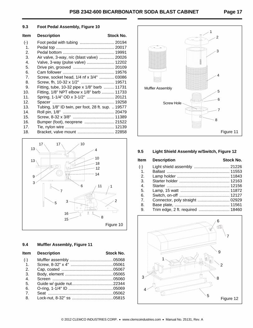
9.3 Foot Pedal Assembly, Figure 10
Item Description Stock No.
(-) Foot pedal with tubing .............................. 20194 1. Pedal top ................................................... 20017 2. Pedal bottom ............................................. 19991 3. Air valve, 3-way, n/c (blast valve) ............. 20026 4. Valve, 3-way (pulse valve) ........................ 12202 5. Drive pin, grooved .................................... 20109 6. Cam follower ............................................. 19576 7. Screw, socket head, 1/4 nf x 3/4" ............. 03086 8. Screw, fh, 10-32 x 1/2" ............................. 19571 9. Fitting, tube, 10-32 pipe x 1/8" barb ......... 11731 10. Fitting, 1/8" NPT elbow x 1/8" barb ........... 11733 11. Spring, 1-1/4" OD x 3-1/2" ........................ 20121 12. Spacer ...................................................... 19258 13. Tubing, 1/8" ID twin, per foot, 28 ft. sup. .. 19577 14. Roll pin, 1/8" ............................................. 20479 15. Screw, 8-32 x 3/8" .................................... 11389 16. Bumper (foot), neoprene .......................... 21522 17. Tie, nylon wire ........................................... 12139 18. Bracket, valve mount ................................ 22858
Figure 10 9.4 Muffler Assembly, Figure 11 Item Description Stock No.
(-) Muffler assembly ...................................... 05068 1. Screw, 8-32" x 4" ..................................... 05061 2. Cap, coated ............................................. 05067 3. Body, element .......................................... 05065 4. Screen ..................................................... 05060 5. Guide w/ guide nut .................................... 22344 6. O-ring, 1-1/4" ID ....................................... 05069 7. Seat ......................................................... 05062 8. Lock-nut, 8-32" ss .................................... 05815
Figure 11 9.5 Light Shield Assembly w/Switch, Figure 12 Item Description Stock No.
(-) Light shield assembly ............................... 21226 1. Ballast ....................................................... 11553 2. Lamp holder .............................................. 11843 3. Starter holder ............................................ 12163 4. Starter ....................................................... 12156 5. Lamp, 15 watt ........................................... 11872 6. Switch, on-off ............................................ 12127 7. Connector, poly straight ............................ 02929 8. Base plate, ................................................ 11561 9. Trim edge, 2 ft. required ........................... 18460
Figure 12
5
4
3
1
8
2
7
9
6
10
17 10 17
13
13
16
12
14
4
7
5
8 16
15
3
11
9
2
3
18
1
Screw Hole
Muffler Assembly
2
3
4
5
6
7
8

PSB 2342-600 BICARBONATOR SODA BLAST CABINET Page 18
© 2012 CLEMCO INDUSTRIES CORP. www.clemcoindustries.com Manual No. 25131, Rev. A
9.6 Controls and Plumbing Schematic, Figure 13
Item Description Stock No.
1. Valve, 4-way air ............................................ 12203 2. Adaptor, 1/8" NPT x 1/8" barb ...................... 11732 3. Bushing 1/4"x 1/8" NPT brass ...................... 02010 4. Adaptor, 1/2" NPT x 1/2" male flare ............. 11351 5. Hose end, 1/2" barb x 1/2" female swivel .... 15002 6. Hose end, 1/2" barb x 3/8" male NPT ......... 06369 7. Blow-off nozzle .............................................. 13116 8. Hose, 1/2" ID air, specify feet required ........ 12472 9. Tubing, 1/8" ID urethane, specify feet required .................................. 12475
10. Tubing, 1/8" ID twin urethane specify feet required .................................. 19577 11. Foot pedal with tubing .................................. 20194 12. Bushing, 1/2" x 1/8" NPT brass .................... 03991 13. Valve, 3 way .................................................. 12202 14. Tee, 1/8" tube barb ....................................... 11734 15. Nipple, 1/8" NPT hex .................................... 01962 16. Actuator, air pilot ........................................... 19123 17 Regulator with gauge, 1/4" ........................... 12050 18. Adaptor, straight 1/4" male NPT x 3/8 tube .......................... 11736 19. Bushing, 1/2"x 1/4" NPT .............................. 01801 20. Tubing, 3/8" OD poly, specify ft. required .... 12478 21. Adaptor, el. 1/4" male NPT x 3/8" tube ........ 11685 22. Valve w/actuator, 3/4" ................................... 25081
Figure 13
21, 19
6
2, 12
7
8
4
2, 3
2, 3
9
10
Muffler Located inside the cabinet
11
Pedal shown without top for clarity
To "OUT" Port
To "IN" Port
To "OUT" Port
To "IN" Port
4
13 2
2 13
2
2
14
10
15
13
16
2
17
8
1
20
10
9
18
5
5
Tee, located inside cabinet skirt
422
5

PSB 2342-600 BICARBONATOR SODA BLAST CABINET Page 19
© 2012 CLEMCO INDUSTRIES CORP. www.clemcoindustries.com Manual No. 25131, Rev. A
9.7 Blast machine and Accessories, Figure 14
Item Description Stock No.
1. Seal, pop-up, rubber ..................................... 01245 2. Pop-up valve and shaft ................................. 01242 3. Handle, 1/2" ball valve ................................... 01252 4. Valve, 1/2" NPT ball w/ handle ..................... 01241 5. Filter, 1/2" manual drain ................................ 01308 6. Metering valve, abrasive ............................... 25128 7. Coupling, CFA-1/2, 1/2" NPT alum. ............. 00558 8. Gasket, inspection door, 3" x 4" ................... 01249 9. Inspection door assembly, 3" x 4" ................ 01267 10. Gaskets, CQG, for 00558, pack of 10 .......... 00850 11. Valve, 4-way air ............................................. 12203 12. Muffler, 1/4" bronze ....................................... 03988 13. U-Channel seal, specify ft. required ............. 19071 14. Valve, 1/2" inlet, bicarb-cab ........................... 25095 15. Filter/regulator w/ gauge, 1/2" ....................... 05530 16. Hose 1/2" x 16-ft blast coupled with items 17 & 18 ....................... 01251
17. Coupling, 1/2" blast hose, CQA-1/2 ............. 00599 18. Nozzle holder, CHE-1/2 ................................ 00577 19. Nozzle, ASV-3, 3/16" orifice x 6" venturi ...... 27014 20. Nozzle, optional CT type, 1-3/4" long CT-2, 1/8" Orifice ........................................ 01351 CT-3, 3/16" Orifice ...................................... 01352 21. Nozzle washer, NW-1, pkg. of 10 ................. 21580 22. Adaptor, 1/2" NPT x 1/2" male flare ............. 11351 23. Hose end, 1/2" barb x 1/2" female swivel .... 15002 24. Lock pin, coupling (package of 25) ............... 11203 25. Hose, 2" vacuum, bulk, 5-ft required ............ 10332 26. Valve w/actuator, 3/4" ................................... 25081 27. Hose, 1/2" ID air, specify feet required ......... 12472 28. Adaptor, 1/8" NPT x 1/8" barb ...................... 11732 29. Bushing 1/4"x 1/8" NPT brass ...................... 02010 30. Nipple. 1/4" brass hex ................................... 02808 31. Pusher line assembly, 11" flexible ................. 24621 32. Adaptor, 1/2" NPT x 3/4 JIC ......................... 25084
Figure 14
5
13
21
2 1
3, 4
6
7
8
9
10
11
12
3, 4
13
14 15
17 16 18 19
27
23
23
24
25
22
29
28
30
22
26
20
22
32
31
PSB 2342-600 BICARBONATOR SODA BLAST CABINET Page 20
© 2012 CLEMCO INDUSTRIES CORP. www.clemcoindustries.com Manual No. 25131, Rev. A
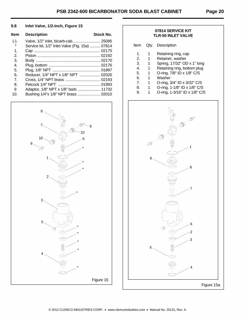
9.8 Inlet Valve, 1/2-Inch, Figure 15
Item Description Stock No.
(-). Valve, 1/2" inlet, bicarb-cab ........................... 25095 * Service kit, 1/2" Inlet Valve (Fig. 15a) .......... 07814 1. Cap ................................................................ 02175 2. Piston ............................................................. 02192 3. Body .............................................................. 02170 4. Plug, bottom .................................................. 02176 5. Plug, 1/8” NPT .............................................. 01897 6. Reducer, 1/4" NPT x 1/8" NPT .................... 02026 7. Cross, 1/4" NPT brass .................................. 02193 8. Petcock 1/4" NPT ......................................... 01993 9 Adaptor, 1/8" NPT x 1/8" barb ...................... 11732 10. Bushing 1/4"x 1/8" NPT brass ...................... 02010
Figure 15
07814 SERVICE KIT
TLR-50 INLET VALVE Item Qty. Description
1. 1 Retaining ring, cap 2. 1 Retainer, washer 3. 1 Spring, 17/32" OD x 1" long 4. 1 Retaining ring, bottom plug 5. 1 O-ring, 7/8" ID x 1/8" C/S 6. 1 Washer 7. 1 O-ring, 3/4" ID x 3/32" C/S 8. 1 O-ring, 1-1/8" ID x 1/8" C/S 9. 1 O-ring, 1-3/16" ID x 1/8" C/S
Figure 15a
1
8
7
6
3
4
9
5
1
2
3
4
10
7
8
9 6
*
*
*
*
*
*
*
*
*
5
2
10
9

PSB 2342-600 BICARBONATOR SODA BLAST CABINET Page 21
© 2012 CLEMCO INDUSTRIES CORP. www.clemcoindustries.com Manual No. 25131, Rev. A
9.9 Dust Collector, Figure 16
Item Description Stock No.
(-) Repair kit, diaphragm pulse valve ............ 21600 1. Valve, 1" diaphragm pulse ........................ 19578 2. Valve, 3 way ............................................. 12202 3. Adaptor, 1/8" NPT x 1/8" barb .................. 11732 4. Nipple, 1/8" NPT hex ................................ 01962 5. Actuator, air pilot ....................................... 19123 6. Adaptor, 1/4" male NPT x 3/8 tube ........... 11736 7. Petcock ..................................................... 01993 8. Filter cartridge, 12" x 30", SB .................... 25967 9. Wing nut, 1/2" NC ..................................... 20108 10. Gasket, 5/16" x 1" adhesive backed, specify feet required .............................. 00187 11. Latch assembly ......................................... 11876
12. Hose, flex, 4", 1 ft. minimum order ........... 12447 13. Clamp, 4" hose ......................................... 11577 14. Dust container assembly includes items 12 & 13 .......................... 23411 15. Washer, 1/2" ID x 1-1/16" OD ................... 03515 16. Elbow, 1/4" brass st. ................................. 02027 17. Washer, 1/2" external lock ........................ 21699 18. Tubing, 3/8" OD poly, specify ft. required . 12478 19. Regulator with gauge, 1/4" ....................... 12050 20. Motor, exhauster, 1 HP, 115/230,1-ph, ....... 12314 21. Plate, motor mount, 600 cfm .................... 12004 22. Housing, exhauster, 600 cfm .................... 12272 23. Paddle wheel, 600 cfm .............................. 12334 24. Clamp, 6" ....................................................... 00750 25. Screen, 600 cfm exhauster outlet ................. 27054 26. Nipple, 1/4" brass hex ................................... 02808
Figure 16
1 2
3
16
18
5
7
8 17
15
12 13
14
10
9
4
6
19
20
21
23
24, 25
10
22
26
11