
aashto.mbakercorp.com PS-I Simple...225 mm L___r- embedment 1350 No. Face of bockwolll I-----' at...
30
L 0 0 * ** -0.673 +0.534 Normal to abutment Light pole foundation End of slob Sta. 125+99.890 Beginning of bridge Beel( o Bacl(\G Ste. 126 1 00.000 29,728 29,500 High water End of bridge boe o boewoll Sta. 126 1 29.500 C.G.Sto. 126+45.000 C.G. Elev. 320.750 v.c = 60.000 End of slob Sta. 126+ 29.618 Finished grade Elev. 320.6 ( I 977) Finished grade Vertical curve Exp. Exp. Fill Fill --------- ---- ---- --- ,- -- ------, ·-------------· Existing Ground line Roadway l excavation f --- -2 Ordinary high water Elev. 313.5 and bockfill Sta. Elev. Elev. (Top ABUTMENT ABUTMENT B A - - - - - - =------ - - ------ - ----- -- - SECTION ALONG CONSTRUCTION Face of bockwall Abutment A j - � - - - - - - - - - - � - � 2 � 8 �.� 8 '.! 1 � 5 ----- ----- --� - J Face of back wall To I 26+00.33 I 321.05 I 320.838 I I of bockwolll , I I , I I / I 0 0 , ' ' along construction i Abutment B Toe of fill 1 4,00 0 0 0 ** Toe of fill , = 7= = ::���1 �,:�:� , - -- - , , � , - �_J�ij 1 � 1 i�--�-------~�,� , - - - � , :<�,� , � ) �·�, _ =_ =_= _= _ =_ =_ = _ =_ = _ � _ ; _ \ 1 1 I I I \ 1 1 I � I II I \ / '/ I , Face of / / / -- - -- - -- r- - 1 ,' 1 ,' 0' sidewalk curb ' , ' , ' ,r - -- , ' 0 0 Radial I I I I II� I / fl/ I I I I , 1 , , ' Radial , , , ,,- - � ' -Buried Approach Slab I I J �� I I / I I I I , I I I I / I 1 1 I � // I I I I / I 1 1 I I t I ' 25 ° -oo·-oo" ,/ / / // � / / / , , ' ��-- 31 ° -52 ' -45 " / , , I I L / 1 1 I � 0 / I I ,' ,' , ' / > , , , , ' Sta. I 26+29.146 / / / // / , ' / - ,,�7 / 0 , , ,' , Elev. 320.878 I I I I I / I I I I q+ , ' , , ' , ' Elev. 320.665 , , / Construction i I I I ; I I I I , / I I , I I \ 0 0 , ) I , , , , (Top of bockwalll I I I Buried Approach Slab Sta. I 25+90.432 Elev. 320.300 Scour protection wall by others I I I I I I I I I I I I I I I I I I I I I I I , I I I I I I I , , I I I ; / I / I I ; I I I I I I ; I I I I / I ; I I / I , / I I I / I I I I / , I I I / / I / I * *' I I I I / 0 , 0 I , ' N Face of sidewalk curb N I �) / I I // L Face > of median I I I I I __ _+- __ r I curb , I , , I ; ; I / I I I I ,' I , / ,, .// I I I I I ; .- / / / / . f/ . I I ; I / I / 0 / / / / / 2 0 0 ' /,1 ,' / I / I / ////g , 0 � 0 0 PLAN I I / 0 0 / / / / / ,✓ s / / / , ' 4 I I I, / / / / / / / / / / I / / / / I I I ; I I I / I I I I I / / I I , / I I , , I I / , , I I I ; I , , / h , , 1, I , / , I I / I I , I / I I / , (, I - - - ----- ---- I I , I I I / I I I I I / I , I I / I I I , ' To I I I I / I , I I / Loop Detector typ. E xtended deck slab No. Description Dote l � c s � u P = E = R �v� 1 = s E = D � , - - - The original approved title sheet, including original signatures, is filed in the VDOT Central Office. Any misuse of electronic files is illegal. Violators will be prosecuted to the full extent of the applicable lows. REVISIONS DESIGNED: DRAWN: CHECKED: Not to scale For Table of Revisions, see Sheet 2. FHWA REGION STATE ROUTE FEDERAL AID STATE SHEET - --------- -------------- , PROJECT ROUTE PROJECT NO. GENERAL NOTE: Width: 1650 mm sidewalk, varying roadway, varying median, 11,700 mm roadway, 1650 mm sidewalk. Overall width 27,900 mm foce-to- foce of roils. Span Layout: 1- 28,000 mm prestressed concrete 1346 mm Bulb-T beam simple span. Capacity: MS18 loading and alternate military loading. Drainage Area: I 05.7 square kilometers. Specifications: Construction: Rood and Bridge Specifications, 1997. Design: AASHTO Standard Specifications for Highway Bridges, 1996; 1997, and 1998 Interim Specifications; and VDOT Modifications. These plans ore incomplete unless accompanied by the Supplemental Specifications and Speclal Provisions Included In the contract documents. Design loading includes 1.0 kNlm 2 allowance for construction tolerances and construction methods. The use of prestressed deck panels as stay-in-place forms will not be permitted. Concrete in prestressed concrete beams shall be Class 55. Concrete in superstructure including sidewalks, roils, terminal walls, and medians shall be Closs 30; in abutments, Class 25. Prestressed concrete in beams shall be Closs 55 having a minimum compressive cylinder strength at 28 days equal to 55 MPo and a minimum compressive cylinder strength at time of release of strands equal to 40 MPo. Deformed reinforcing bars shall conform to ASTM A6 I 5M and shall have a yield strength of 420 MPa. All reinforcing bar dimensions on the detailed drawings ore to centers of bars except where otherwise noted and are subject to fabrication and construction tolerances. H-Piles in abutments hove a design capacity of 490 kN per pile and shall be driven to refusal. Bridge No. of existing bridge is Structural approach slobs ore not included in the bridge contract. B.M.: Chiseled square on southwest corner of traffic signal box located 2.698 m Rt. of Sta. 139+75.54 I Route 460 survey traverse Line Elev. 319.326 m. All dimensions are shown in millimeters <mm) unless otherwise noted. All elevations ore shown in meters (ml. Symbol 0 = diameter. Recommended for Approval: � Approved: METlC Date: Sheet I of 30
Transcript of aashto.mbakercorp.com PS-I Simple...225 mm L___r- embedment 1350 No. Face of bockwolll I-----' at...

L
0 0
0) ""
*
**
-0.6 731/. +0.5341/.
Normal to abutment Light pole foundation
L1. End of slob Sta. 125+99.890
Beginning of bridge Beel( o::f Bacl(\v'GII Ste. 126 1 00.000
L1. 29,728
29,500
High water
End of bridge boelz o-F boel<:woll Sta. 126 1 29.500
C.G.Sto. 126+45.000C.G. Elev. 320.750v.c = 60.000
End of slob L1. Sta. 126+29.6 18
Fini shed grade Elev. 320.6 ( I 977) Finished grade Vertical curve
Exp. Exp.
Fill L1. L1. Fill
--------------------,-
-- ------, ·-------------· \_ Existing Ground line Roadway
l excavation f--- - -- ----,,2 Ordinary high water Elev. 313.5
and bock fill
Sta. Elev.
L1. Elev.(Top
ABUTMENT ABUTMENT B A
--------=--'------ -----------------
SECTION ALONG CONSTRUCTION ct_
Face of bockwall Abutment A j
-�r-----------
-:;-:�-�2�8�.�8'.!.1 �5------- - - - ---�k--J Face of back wall
To
I 26+00.33 I 321.05 I 320.838 I
I of bockwolll
, I
I
, I
I
/ I
0 0,.__ l[)
' '
along construction i Abutment B
Toe of fill
1 4,000
0 0 "1"
**
Toe of fill
,1==-=76===::��t:�1�,:�:�,----1-,,�,-�_J�ij1�1:_-fi�--�------..,....-~i1�1L...,;.�,�,-----;�,:<�,�, /2�
)
�·�,_=_ =_=_= _=_=_=_= _=_�_;_ \11 I I
I \ 11
I � I II I \
/ '/ I ,;;;- Face of / //
--------r--
1 ,' 1 ,' 0' sidewalk curb ' ,',' ,r- - -,'
0 0 LO LO
Radial II
II
II� I
/fl/
II
II
, 1 , "' ,' Radial , , , ,,--�'-Buried Approach Slab I I J �� I I
/ I
I I I ,..,
I I
I I / I 1 1
I �
// I I I I / I r,.: (/) 1
1 I I t I
'25°-oo·-oo" ,/ / / // � Q)
/ / / , ,' ��-- 3 1° -52 '-45" / ,,
I
I L /
11 I
� 0 / I I ,' ,' ,' / z-°' > , , , ,' Sta. I 26+29.146
/ / / // .;::.. / ,' / _,,- -,,�7 / -:---.0 , , ,' , Elev. 320.878
I I I
I I
/ I
I I
I 1_q+ ,' , ,' ,' Elev. 320.665 , , / L1.
Construction i I I
I ; I I
I I
, /
I I
, I I
\ 0 0 a,
,.__
) I , , , , (Top of bockwalll
I I I
L1. Buried Approach Slab
Sta. I 25+90.432 Elev. 320.300
Scour protection wall by others
I
I I
I I
I I
I
I I
I I
I
I I
I
I
I I
I
I
I I
, I
I I
I I
I I
, , I I
I ; / I
/ I
I ; I I
I I
I I
; I
I I I /
I ; I I
/ I
, /
I I I /
I I
I I
/ , I I
I /
/ I
/ I
** ' I
I
I
I / 0
, 0 I
"1"
,' N
Face of sidewalk curb
N
....
I
�) /
I I
//
(I)
L CJ Face > of median
I
I I
I I __ _L,__+- __ _,_r I
curb,
I
,, I
; ; I / I
I I
I ,' I,
/ ,, ('_
.// I I I II
-+-;..s .- / // / . f/,-. I I
; I
/ I /0 / / / / / 200 ' /,1 ,'
/ I / I
/
////g ,.__
0 l[) �
0 0 "1"
PLAN
I
I
/ 00/ / / /. /
,✓ s / / / /, ,' 41\1 I I I, / /
//
/ / /. /
/ / I// /
/ I I I ; I
I I/
I I I I I /
/ I I , / I
I , ,
I I / ,, I I I
; I , , / h ,, 1,
I
, /
, I
I
/ I
I
, I
/ I I /, (,
I - -1- - - - - - - - - - -
I I
, I
I I
/
I I
I
I I
/ I
,
I I
/
I I
I ,
' To I
I I
I
/ I
, I
I
/
Loop Detector typ.
L1, Extended deck slab
No. Description Dote
l
� 1-cs�uP= E=
R�v�1
=sE=
D�,-- -
The original approved title sheet, including original signatures, is filed in the VDOT Central Office. Any misuse of electronic files is illegal. Violators will be prosecuted to the full extent of the applicable lows.
REVISIONS DESIGNED: DRAWN: CHECKED:
Not to scale For Table of Revisions, see Sheet 2.
FHWA REGION STA TE
ROUTE FEDERAL AID STATE SHEET- --- - - - - - --+-- -------------------,
PROJECT ROUTE PROJECT NO.
GENERAL NOTE:
Width: 1650 mm sidewalk, varying roadway, varying median, 11,700 mm roadway, 1650 mm sidewalk. Overall width 27,900 mm foce-tofoce of roils.
Span Layout: 1-28,000 mm prestressed concrete 1346 mm Bulb-T beam simple span.
Capacity: MS 18 loading and alternate military loading.
Drainage Area: I 05. 7 square kilometers.
Specifications: Construction:
Rood and Bridge Specifications, 1997. Design: AASHTO Standard Specifications for Highway Bridges,
1996; 1997, and 1998 Interim Specifications; and VDOT Modifications.
These plans ore incomplete unless accompanied by the Supplemental Specifications and Speclal Provisions Included In the contract documents.
Design loading includes 1.0 kNlm2 allowance for construction tolerances and construction methods.
The use of prestressed deck panels as stay-in-place forms will not be permitted.
Concrete in prestressed concrete beams shall be Class 55. Concrete in superstructure including sidewalks, roils, terminal walls, and medians shall be Closs 30; in abutments, Class 25.
Prestressed concrete in beams shall be Closs 55 having a minimum compressive cylinder strength at 28 days equal to 55 MPo and a minimum compressive cylinder strength at time of release of strands equal to 40 MPo.
Deformed reinforcing bars shall conform to ASTM A6 I 5M and shall have a yield strength of 420 MPa. All reinforcing bar dimensions on the detailed drawings ore to centers of bars except where otherwise noted and are subject to fabrication and construction tolerances.
H-Piles in abutments hove a design capacity of 490 kN per pile andshall be driven to refusal.
Bridge No. of existing bridge is
Structural approach slobs ore not included in the bridge contract.
B.M.: Chiseled square on southwest corner of traffic signal boxlocated 2.698 m Rt. of Sta. 139+ 75.54 I Route 460 survey traverse Line Elev. 319.326 m.
All dimensions are shown in millimeters <mm) unless otherwise noted. All elevations ore shown in meters (ml. Symbol 0 = diameter.
Recommended for Approval: �
Approved:
METflllC
Date: Sheet I of 30
The Bridge As-Built Plans and corresponding BrDR Models are provided for example only and may not represent the modeling techniques used by your agency.

-
L N
0
0
ro '"
ro
N
_Q
0
28,815 (Arc)
Radial Radial
6'/o Construction (i. 3" ro'-z 'tr, Circular Curve Lt. O :i
_ Radius = 240.000 m <o ' ' v'
rChord Sta. 126+00.33
\ cP •
It
I- - -
Face of Backwall 28,800 <Chord) Abutment A
I Face of backwall Abutment B
I
BRIDGE LAYOUT Not to scale
ESTIMATED QUANTITIES
Concrete + + Reinforcing Epoxy Pre stressed Aluminum Bridge Steel PIie Point Structure Steel Coating Concrete Railing Deck Piles For 250 mm Excavation
Reinforcing Bulb-T Beam Grooving 250 mm Steel Pile m 3 Steel 1346mm 0 0 0
<27m-30ml m2 3
Class 30 Class 25 kg. kg. EA. m m EA. m
Superstructure 2'i'l.4 278.0 25,'i'80 28,690 0 + 13 58 -5-96- 616
Footing I 13.5 7025 473 53 125 Abutment A
Neat I 'i' 4.9 170.9 3 'i'90 3650 8
Footing 127.5 8050 574 73 354 Abutment B
Neat 242.5 238.5 "1555 4440 I I
Total 2'i'l.4 278.0 658.4 650.4 15,075 34, 125 36,780 13 77 -5-96- 616 1047 126 479
fil fil fil fil Denotes items to be paid for on basis of plan quantity * Quantity includes 510 kg of epoxy coated welded wire fabric in median.accordance with current Road and Bridge Specifications.
* * Low permeability concrete to be used for construction of entire bridge.Mobilization - Lump Sum
Dismantle and remove structure No. 6245 - Lump SumConstruction Survey - Lump Sum
FHWA FEDERAL AID STATE SHEET REGION STATE
ROUTEI ROUT El PROJECT PROJECT NO.
' .
INDEX OF SHEETS
Sheet No. Description I Plan, Elevatlon & General Notes 2 Bridge Layout, Estimated Quantities & Index of Sheets 3 Substructure Layout & Slope Protection 4 Abutment A, Plan & Elevation 5 Abutment A - Details I 6 Abutment A - Details II 7 Abutment A - Footings 8 Abutment B, Plan & Elevation 9 Abutment B - Details I
10 Abutment B - Details II I I Abutment B - Footings
12 Bearings Details 13 Transverse Section 14 Framing Plan 15 Prestressed Concrete Beam MPCBT-1346
- 16 Intermediate & End Diaphragms Details 17 Deck Slab Plan
Sta. I 26+29.146 18 Deck Slab Elevations 19 Preformed Elastomeric Joint Sealer 20 Aluminum Railing 21 Aluminum Railing 22 Aluminum Railings Miscellaneous Details 23 Bridge Conduit System 24 Reinforcing Steel Schedule I 25 Reinforcing Steel Schedule II
26 Engineering Geology 27 Engineering Geology 28 Approach Slabs Layout 29 Approach Slab Abutment A 30 Approach Slab Abutment B
Preformed Dry Riprap Porous Pipe Elastomeric CL Ill Backfill Underdrain Joint Sealer 1350 mm 150 mm
0mm to 51mm 0 metric ton 3m. 0 m m
--66--- 8
650 -'H- 78
36
730 -94-101 fil 1,2,4,5,8,9, 13, 17, 18,24,25,28,29,30 5/8/08
48 Rev. No. Sheets Revised Date
-6-€,- 8 1380 +6-5- 179 84 TABLE OF REVISIONS
fil fil fil
BRIDGE LAYOUT ESTIMATED QUANTITIES
INDEX OF SHEETS fil Revised Quantities 5/8/08
METPIIC Date I Plan No. Sheet No. No. Description Date Designed: .
I Drawn: ..... 2 of 30 Revisions Checked: '.

.... 0 0
....,.
Face of bockwoll
00"' "'1
Abutment A f---+-------i
Sta. I 26+00.330
---------
BH-01
�
Notes:
I . This layout rs to be used for the purpose of locating fill slopes and footing of abutments and retaining wall For details of neotwork. see abutment and retaining ..,"011 details
2. Symbol � denotes boring location. For additional details,see sheets 26 and 27 •
SUBSTRUCTURE LAYOUT Scale: I = I 00
Chord
Face of bockwoll Abutment B Sta. I 26+29.500
--------------------------------
Construction �
000u,
400 3300
3700
000u,
Radial
1.-------7729
FHWA FEDERAL AID STATE SHEET REGION
ST A TEt-RO::-:U
-::T
:=E
r---::--::-�-::-:----+-----.------=------------l PROJECT ROUTE PROJECT NO.
I 1__-----------77
* * Normal to abutment
Limit of measurement 1----i for payment
Elev. 314.500 9 Abut. A Elev. 313.500@ Abut. B
min 225 mm L___r-embedment �
1350
No.
Face of bockwolll I-------' at abutment J
r,;
min 225 mm embedment
Dry Rlprop Closs Ill
-
' .
,,.
Rlprop filter cloth bedding
Descrip tion
SLOPE PROTECTION Not to scale
STRUCTURE AND BRIDGE DIVISION
SUBSTRUCTURE LAYOUT SLOPE PROTECTION
Da te Des 1 gned: . -- .. t--_D_ac.ct..c.e_-+----'-P.:.:I a:.:.;nc...:.:.:No::.:._+-----"'S hc::e:'..::e'...!.t--!!:N o,'._!•-1
t--.1...----------'-----IDrawn: ...... 3 of 30 Revisions Ch ecked: •.

-
L .,,-0 0 ro.,,-0:, N _Q
?-°'oO�
• • For deta ils
=
. < --E--s-e_ e_ s_h_e_e_t _6_----------------------- 17,580- - - - - - - -- - - - - - - - - - ------ - - - - - -- -- I 0,300- - - - - -----'<- -----s�
-- 250
Line thru centers of bea ring
Const. <t \ Elev. 321.05 I I:\
E lev. 320.838 ill l[) 0r-- 0- ,...,
l[) N l[)
7 o,00 � \ 1/--- AW 16 12
�'(\/V /135 °-oo·-oo"\
Face of Back wall \
\ \' '
rS ta. 126+00.331
I i •
� '\ � AW l61 I
AHl302� �,___ )��K .A7AHl301*
66 °-30'-00" / \1-- II " " ' \\ " / ,; " � " I
\' .' '
I I I
5
I -· I I I I I I I \
I I /
0 I I I O I I
� 1- / � \\11 •
--+-__
\_,_
\
_•+-+:
+-t:; t-- ----+-.----;\,_....\:� i • \\. : -- -+-__ \..,_\__,· -:+
: ---+-+-\7'��-+---+-:+-::-;-+-+- . -�\�
\·-+-�-+-:+-
:---lr-.-\ .... _\•+-g *�_\_,_\_•+-�----++-
• \,
\-\
\ -
'b�i/,,, • � I
\ \\ \ \ \ \ \\ / \ \ \ \ \ w
'---+-'<+-1
�--00�______,\
,-----___ +-----',----_\ ___ \_\ __ \Y.....,...._
�-61 °-3-3'-�8___.___" -------.-1-\-------++---,---+---+-----------\ • \" � • :'\
\ \
I \ •
-I • \
\
C,
* Field bend a s needed* 4 E q ua l spaces
** 8 E q ua 0 8 E q ua
I I
spaces spaces
For see
E lev.
- 1100 -
= 1200
deta ils sheet 6.
32 I .80 I
\ \ \ \ \ \
\ \ \ L, ' r. B ' ' ' 298 Chord to , , \
3 spa. @ 20\00 _
-----'<"'�'t. earns---\-- \ \ -- Abutment B --- 1------600 typ. \
6000- ---i-�- -- 3 spa. @ 2729 - 8187 - - - - ----E--- 2431-----1 -- -- - - - - -- 4 spa. @ 2729 = I 0.916 - - - - - - --� 1750 �
329 --+-I 1--- ------------------16,936------------------�i----- - - - - - - - - -- - -- 13, 150--------------------i f----1- 627
�
-----------------------17,580 14, 177- - - - - - - - - - -- - - ---i
PLAN Not to sca le
& 17,212 & 13,419
AV 1302, AV 1303, AVl304 & AF1319 AVl302, AV 1303, AV 1304 & AF1318 56 spa. @ 300 = 16,800 43 spa. @ 300 = 12,900
150-------S> -(A\ --- 150
/:
_E lev. 32 1.464 & � y � AH 1302 <E.F .l & Elev. 320.350
AHl301 <E.F.l�
FHWA FEDERAL AID REGION STATE
ROUTE PROJECT
Note:
ROUTESTATE
PROJECT
I. For footing reinforcement, see sheet 7.
SHEETNO.
35(4)
2. Back fill sha ll not exceed E lev. 318.400 prior to placementof the superstructure.
3. For deta ils of ra iling, see sheets 20 thru 22.4. For details of bea ring s, see sheet 12.
� 6001
600----a>
Line thru centers of bea ring
75 typ.7 �
Cl. 0(/) tn
• CX)
(I) II
l[)
75 typ. AVl301 7 spa. @ 150
= 1050
i--X x�
7 \ >- \ >-
V7 L
'
AHl6 series -
I
Bae rFac e of
kwall
t 0 l[) 'l[)
�
7 '
Bea m
TYPICAL ANCHOR BOLT LAYOUT Sca le = I :25
Bea m X y o(
B l 411 238 59°-59'-36"
B2 thru BIO 418 226 61° -33'-38"
111 & -H
\ -- & E lev . 320.806 B l I thru B 13 423 215 63 °-00 '-00"
7
7 '
N < - . cD ( - . s: <( I
SJ'( - .
&
�D-�D-
I I I
r ',- -
(/) I L CJD:r: <(
.r:+-•-3:
C CJ)•-<(
-----r
A ff
**
()
7-AHl604 ----- -r
B
* *
0
---
E lev. 315.700 _/
- --- - -re
*
-15 Wa sh - - - -------- typ. ----------------------- ------7 --- --
, , _,_
' ' ' --7 -----rD rE
.e_5 typ. F
rG ,� --------, ' ----------------------
!\
6 eq. spa. typ.
0
AVl301
\
' ' , '
\_ AH 1302 <E.F .l JAH 130 I <E.F .l
0 0
' -
f--
�
�50
, ,
, AH 130 I <E.F.l 150 6 spa.@ 300 1�
•yp.1800 = <D '-
_j
-rJ '
' ---
5 eq. AHl302 <E.F.l 6 spa.@ 300 -spa. 1800 =
---
, ID 0
� �300 min.la p typ. so-
& AF l319
ELEVATION ( piles & footing reinforcement not shown for clarity.)
Not to sca le
rK' r
L
� 7-AH 1603 typ.
0
AVl301 & AF l318
&
---------------r
M
3 eq. spa. 7
4 ' '
I I I I
--N \
" \
' I I I '
I I
I I
0' I I I
' I '
I I I I
- · ,..- · co' e- · s:
�<( I
-I r,,.. &
METPIIC
+- (/) •- L � CJDC
CJ)I = <l <(
LD, Extended deck slob 5/8/0B
Dote Designed: 1---� -- - - - -�- ----1Drawn: '""'
No. Description
Revisions Checked: I
SEAT ELEVATIONS
A 3 19.868 H 319.253
B 3 19. 796 J 319.153
C 319.723 K 319.054
D 319.650 L 318. 955
E 319.550 M 318.856
F 319.45 I N 318. 793
G 319.352
STRUCTURE AND BRIDGE DIVISION
ABUTMENT A PLAN & ELEVATION
Dote Pion No. Sheet No.
4 of 30

-L
Lf) 0 0
00 s,-00 N _Q
Elev. 315. 700
105
-- -- - - - - - - -5330- - - - - - - - -----i RW 130 I, for spacing see railing details
AW l 301 N.F. & AW l 902 F.F. 13 Spa.@ 225 = 2925
AW l 303 E.F. 75 7 Spa.@ 300= 2100
..!+---- -------- ----+-+- ---- -----1
125� � ol Elev. 320.806 \
\ r-75 !It:========:!::: .===:::.=;:========::::.IP.
'
I
t
. • LL
½LL z
<.D L{)0 0 I") ,....,_ -3::3:: <[ <[
.
AF1315 N.F. & AF2516 F.F.
.
.
Elev. 318.350 _j
- 500 (AF25 I 6)
L100
Elev. 320.844
0
LL 0 I")
LL 0
t-lfV 0
0 •NN 0 N 0. II
3:: <I)
<[ t-
0 u.'. 0
• I") w 0 @0
"'" L{) 0 •,...., 0 - 0.11
3:: <I)
<[ L{)
375 min. lap
400 400 ----�-�- --2400- - -�
n
RW l 301 '
�! AW 130 I . AW 1902
�
. Porous back fill AW 1305 •. 450 .,, .
AW 1306
---1-AF25 16 �----+---fJI·�.
t :;: l��----l-AW 1304
AF I 3 I 5-+-�1-11 .. 300
L_�; �:I .- !
AF25 I 3
•
AF25 I I f ... ·'• �:1::1 ., .• uty-AF1914
/AF1912
See Road Plans (Typical Section) for additional excavation and backfill requirements at Abut. A to Elev. 314.500
-
-
- I �AF25 I 3 AF l 903�
15 Wash
FHWA FEDERAL AID ST A TE
REGION ST A TE1---,1
- - - -- - -1-- -� --- - - -- - - --� SHEET
ROUTE1 PROJECT ROUTE PROJECT NO.
400 1000
175-
300
=
AV l 302 --�,
AV 1303 ---._-._
35(5)
525
-. �)fo)�,;.
"-+-1-- - - - - -������ ��ckfill -
subgrade. ' 1400 �
AH 130 I --�--i 7._iap typ. b JH----+1----'-
f=t ����kd 450
n AV l 304 AH I 603 - . a
-
� ,_1�f--- - - - - - - ---+�-+-- -�-CL HP 250x62
steel piles
I> p Weephole - form
' h
I with 150 mm 0
VIEW@
Elev. 315.700
2200
RW 130 I, for spacing see ralllng detalls
Elev. 321.817 \ /
Elev. 321.801
t=========:=::::i
75
I
' ' I I
r-"T-1
I I I I I I I I I I I I I I I I I I I I I I I I I I I
. .
AW 1308 E.F. 7 spa.@ 290=2030
I I I I I I I I I I I I I I I I I I I I I I I I I I I I I I
LL . w
0 -t') -3:: <(
i
f L{) t-N
. LL
w
0t') -3:: <[
L{) t-N
@� <.D ·-
0 0. II
V)
<.D
0 0 0 ,...., II
0 0
@
(])
0 0. V)
0 -
! . : . , ·/1. :
I ; •, •.; I
I I I I I I I
. ;:,. � f . . . IL15
I
I I
·tr. ·• .._<) I
• • • , .11, � I • � � I
I ' ' I
7
VIEW(Retaining wall stem not shown)
375 �---2450------i
--- - -- -3200- - - - -�
SECTION D-D
375
Not to scale
- p non-rigid tubing. b
I> n
AV 130 l-t----+11
I -50 mm Crusher
400 min.}lap typ.
Lowest point feasible for free drainage away -from abutment.
See Road Plans (Typical Section) for additional excavation and backfill requirements at Abut. A to Elev. 314.500
-
-
0 0 0
. 0 0. 0 >-, I") +-
'
-,
AH l 301 JJiL!ocf" �)��80\j 'o C'oC)oC'/
� •
-----
---
---
�--------11 _____ .
----
-
.
i------AF1319--..i
" .
n �AF1904
• • , r
"-"- ; ,I T
-t
I T
LJ ,- AF2508 _ uw-
'--
run aggregate.v See VD0T Spec.'·
�Sec. 40 I .03(i)
0 L{) "'"
AF1905
0 Q_ 0 >-, I") +-
- _,_ _ _- --I-+---+-- - - -- - -_J__ _ _J _ __ _
==
METRIC fil No.
,----t-- - - - - - - - ----+------J Ct HP 250 X 62' Steel Piles 375 I 375 --�-----1650------1-,��
-- -- - - -2400- -- - - -�
ABUTMENT A - DETAILSRevise section A 5/8/08
Description Dote - Date I Plan No. Designed: .
Drawn: .... Revisions Checked: .
Sheet
5 of
No.
30

<D 0 0
... .,.
0 0 ,..._ ,.,,
0 U'l ,..._ N
0 lJ'l lJ'l
0...
Elev. 320.30 0
300 CWF I 30 I l 7
t
I;
.. 1--650
J
' ' ' '' '' '' ' ' '
aN
U'l Oo - U'l ,..._ •N00 C>-- :;;,:::::!:�
Cf.
( '\
' ' ' ' ' ' ' '' ' ' '' ' ' '' ' ' ' ' ' ' '
PLAN
El WH l 305 - N.F.
� WH1306 - F.F. -
WV1301 N.F. S. WV I 602 F .F. 37 spaces@ 225 = 8325
Weephole
l I'\ ( I'\
2500 2500
Elev. 315.700J WF1301 N.F. WF2502 F.F.
!.I ELEVATION
\,..,, \ \
Terminal wall \ \ \ \ \ \ \ \
\ .... \ \ \ ' " \ :,
' ' ' '' '' '' ' ' '
I 20 mm Thick ·Jexpanded rubber
Joint filler
r225
1 WV1301
20 mm Thick
-
Ele 321 694 v. .
''''''
N.F. I
I I I I ' ' '
•
-
expanded rubber ' joint filler ' ''''
I j '\ I
.
\ ' ' '
}: �· ' : -
\
'''''''''''' '
' '''''''''''''''''
�
For details. see Sheet 4
• . LL LI.•z LL
,.,, ..is ... 0 0 .,, .,, :i::: :i::: :;;,: :;;,:
. LI. LL
N 0 .,, -:i::: '3::
-0 C 0
LL . z-0 .,,:;;,:
0 U'l N
0 Clllll
N --0Q II
Vl
U'l
0 0 .,, ,.,, I
0 0 ,.,, a, 1/) Cl) 0 0 a
Vl
2500 l�WF13 01 N.F.
175
(piles S. footing reinforcement not shown for clarity.)
N N 0 .,,
IX) ,..._ <£1
WH
WH
WH
WV
WH
0 U'l 0 N
0 0 a,
U'l ,..._ ,.,,
1305
1303
1304
1301
1301
375 Min. lap
t -
205 typ.
1· :! ci0 >,N +- ,_ -
I I
lJ'l I ,..._ I U) N I 0 0 lJ'l @U'l I
N w I LL ·-
I :;;,: 0 I' Q II N Vl I
<£1 I I
I � I 1- -
2-WF2907 typ.14 spa. 9 160 = 2240
- -
2-WF2907
WF2506-
- ,_ -
3 S
·1 �
. -
- -
--
. I- ...
·'-
� -
·CI II 4
I I I
�-- I
-- -- -T
I •
I ..
■- I ·-
' -2 WF2506 J '
* 2 Equal Spaces = 500
' Indicates direction of the batter.
400 550 2750
WH1306 � '
�1 WV1602
1'1 450
·. ·• ;. : .•- WH1302 . ..; :_ ..
•· . ;
ll' Porous back fill
•.- !·,... ..
WF2502 -
50 mm Crusher-run
/ aggregate - See VD0 Specs. Sec. 401.03(1)-
T
paces
FHWA FEDERAL AID
REGION STATE
ROUTE PROJECT
@ 2650 7950 =
-2-WF2506 2-WF1903
-- - -- - --- - -
WF 1904-
- - -,- .. " .. - I- - - -
I
.:flt-- - - - -• -'
FOOTING PLAN
ROUTE
typ. \
- -
WF 1905
2-WF2907
- ·-
-
STATE
PROJECT
SHEET
NO.
35(6)
425
I I
I I
I
I
II
I I
I.I. ,. ... II
I I
. =II II
'-i::::R
'
-�
--
Cf. HP 250x62 steel piles
,,., ,..,,
I I
Face of backwall
�------- �
For details, see Sheet 5
Lowest point feasible for
drainage awa from wall
;ree
_ .... ll__
............
----!(
� ;-WF2907
I "
1301 . .
0 0 WF
WF250 WF 1903- i!;'.,' lJ'l //
WF1904
fl HP 250x62steel plies
.
6
·--
'
J./ I I
I- .... -
I I
I
375
Not to scale
--
-
�3 J
j ! .I / I I ----,-
I
I
900
-- '.
�3
I
I
WF1905 WF1903-
- - -
- - - �
1-------------- I- - -
2050 375
3700
SECTION E-E
0 0
•-
!
-
. 0. >,+-
0 0 0
See Rood Plans (Typical Section) for additional excavation and bockflll requirements at Abut. A to Elev. 314.500
STRUCTURE AND BRIDGE DIVISION
ABUTMENT A - DETAILS II
Date Designed: I---'--------��---. Drawn: .....
No. Description Date Plan No. Sheet No.
Revisions Checked: 6 of 30
r---
0 0
....,.
,---I I, I ,
I I , I, I I
II I
II I, , II r. , , I
I I
I I
, II
, II
-----7
,
I
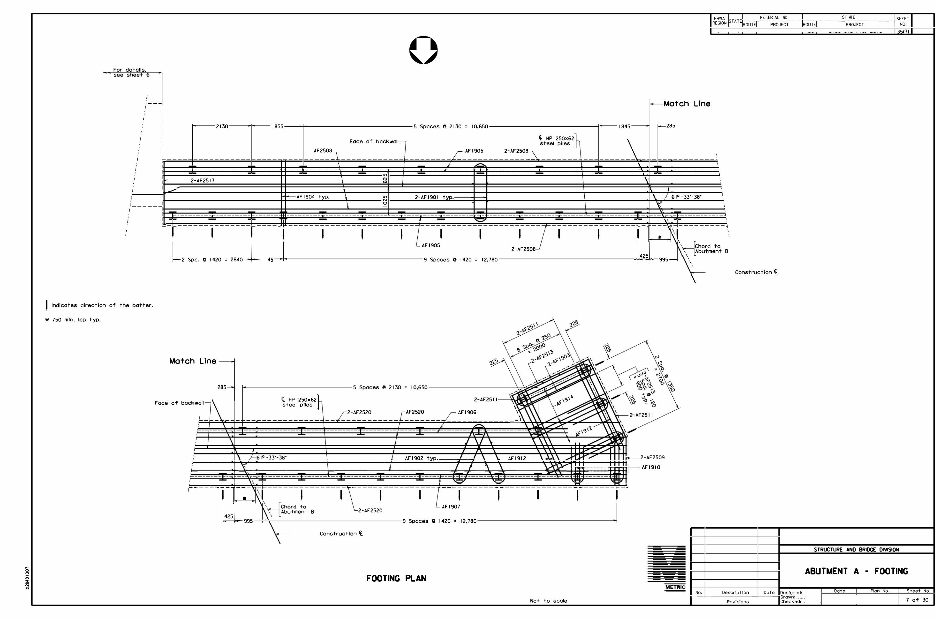
f Indicates direction of the batter.
* 750 min. lap typ.
I I I!:
--
2130 1855
------------------------- --2-AF2517
AF2508_]_
I
- ---- 1---------- ---
AF1904 typ.
5 Spaces @ 2130 = 10,650
Face of back wall-
L_ AF1905
I .......... ----•---------------------------- --1-- - -
N U) .
U'I 2-AF1901 typ.N
0 .
I -
1845 -
Cf. HP 250x62 -
\steel piles -
2-AF2508-�
\ . ---------------------------- -------------
- --\ . \ . . . .
Match Line
f-..-285
.
FHWA 1-----,----FE_ D_E _R _AL_A_ID __ +----r-----S T_ A_T _E _____ ---, SHEETREGION ST ATE ROUTE PROJECT ROUTE PROJECT NO.
35(7)
I ' � I
--------------------. -- . I
' ' . '
� . ' \ '
\, rf:. 1° -33'-38" '
\\ I . '\', .
-------------------- -------- -------------------------- ------- n-------------·-- 1----------------------------------------� ---�--... - ------------\-- - -- - - - - - - - -- \\ --'
- - - � -�
1 ' ' ' ' ' ' ' ' ' ' ' \_, '
*
L, 2840J_ 1145 . I !,,I. \
�
- AF 1905 2-AF2508 ' Chord to \ Abutment B
Spa. @ 1420 = 9 Spaces 9 1420 = 12,780 995- \
\ \
Construction 4.\
Match Line --
285
Face of bockwoll fl HP 250x62steel piles
2-AF2520 AF2520 \
AF1906 \ ------------_)
i AF 1902 typ. ___ r-__ AF 1912--�� --- 2-AF2509 i-------.a.,H�----'-------------,r------------l...._--------+--+-___,;'c-----l�-----+-�12"�K+-l---➔++-H ,__ ____ ---'.,_�1'---"""'-----------+---------'----------+--+--""T-""T _____ ___.�o¥1\
r--
-++.f.:ti:-������.:f':::f.:',l:.l=f�:--AFl910 II
l"----..................... -± ....... ":1--....... ---,"':"---±-........................................................................... T"'" .................................................................................. � ....... ....;;;;;..... ............................ � .................................................................... .a;;;i,. ............................ ""'"'IEI---'�
' * ' ' ' ' ' ' ' ' bl
2-AF2520AF1907
9 Spaces @ 1420 = 12,780 995
Construction 4.
FOOTING PLAN
Not to scale Designed:
1---�------�-----1Drawn: ..... No. Description Date
Revisions Checked:
STRUCTURE AND BRIDGE DIVISION
ABUTMENT A - FOOTING
Date Plan No. Sheet No.
7 of 30

-L
00 0 0
00 '" 00 N .0
* Fi eld bend a s needed * 6 eq. spa. typ.
* * IO spa. @ I 50 = 1500
75 typ. �
I I I I I I I I I I I "'" s
N,
lD " - -
s: 3
<( .,
"'" ,� - -a
&
oo,
o,
Elev.
IJ) L 0 .D
:r: /4
.L+-•-�
CCJ)•-/4
154
320.647 1
' I I I I
-
... - - ,I I I I I I I I I I I I I I I I I I I ,,
Elev. 314.500 /
q_ Weephole
� 6001600 -----
AVl305
FHWA FEDERAL AID REGION STATE
ROUTE PROJECT
i-- ---'<--- -- - - - - - - -- -- I 1,895 - - - - - - - - - - - ----a------------------ - - - 17,589----------------- ----'-"----...-i14,369 -------------------
Construction Ct-� Sta. I 26+29.146 Elev� 320.878 & Elev. 320.665
Line thru cent er s of
400
bearing
AHl310 * Face of back wall0 Lf) Lf) NL{) o:J
* AH 1309L{) 0 r--
0
I I I I I I I I I I I I I I I I I I I I I I I
ROUTE
• \ I ♦I \ • I \ 0 • I I \ • I I \ • 0 ' ' ' r--I I I I I I
I I \ • 0 \ • 0
I I 0 ' I
I \ •• \
I •♦ ' I •
29 °-44'-53" o 0•
�1..r:§)600
• • I I
• • I I I I
I 18° -26 '-23"
• • N • • I I I I I I I I
0 0 "'"
'\ \ 600
Lyp.
typ. 298
Chor d to
�bu tment A
--a-tt--r+-----'c<e-----i Beams
2620-----a-- - - --3 spa. @ 2729 = 8187- - - - -�-----2431--- -- -- - - - - -- 4 spa. @ 2729 = Io, 9 16 - - - - - - - --e----- 2777 _ ___,,,.___ 2000 ----=�- 200011------------------- 14,098----------------�-------------------- 17,986------------------�
-- - - - - - - - - -- - -- 14,155 18,793-------------------- -----i
fil 14 347 ,
AV 1306, AV 1307, AV 1308 & AF1635 47 spa. @ 300 - 14, I 00 -
rF'\ Elev. 320.186 � LV
&
r-7-AHl614 __________________
. -;A-r
B re , r
D
• 1\
\__AHl31 I (E.F .) ** * -
AHl310 (E.F .J 9 spa. @ 300 =2700 �
~ r. 0 ' I -50I I I
AVl30 5 & AF1635
4 spa. @ 3000 = 12,000
PLAN
I '
Not to scale fil 18 247
I AV 1306, AVl307, AVl308 & AF1636 59 spa. @ 300 = 17,700
- �150 Elev. 32 I . 2 7 4 �
II�1 50-----
& �AHl309 (E.F .J AHl310 (E.F .J -
. 7-AH 1613-
--- -----
rE
- ----F-
' '
-�--'
I
____ : __ ; G f 7-AH I 6 15
;:·-
__ -1 5 typ. __ �5
- _V'._<:S_
�t:J
- __ -, ------ --------------------r
L
rM rJ !
4 eq. spa.
, I. 1 500 • I.
" u '
'"
280 typ.
' ' �
r300 min. la p typ.
r.
50-
1500 • I.
ELEVATION
-f--
�
I
1
I
/ AHl312 <E.F.J-
AHl309 (E.F .J � AH 1309 (E.F.J 9 @ 300 spa. =2700 4 eq. 4 eq.
spa. spa.
� r. r.
I I I I
AVl30 5 & AF1636
5 spa. @ 3000 - 1 5,000 -
Not es:
I ""' '
I I I I I I
I I r
-NI
I I ' '
I I ' .
I I I I
.
.
608
Elev. 321 .624
7
l'1 �� N,
lD � - -
s: ;; /4 <
I
00 < D- <u
&
(/) L 0 .D
:r: <(
..c +-.
.
�
C CJ)
<(
"'"
I. For foo ting reinforcement, see sh eet I I.
STATE
PROJECT SHEET
NO.
35 (8)
75 typ. 7�- - -
7 spa. @ 150 rFoce of =1050 Back wall �x x�
(Piles & foo ting r einforcement no t shown for clari ty.) No t to scale
SEAT ELEVATIONS
2. Back flll shall no t exceed Elev. 3 19.000 prior to placement of th esup er structur e.
3. For details of railing, see sh eet s 20 thru 22.4. For details of bearing s, see sh eet 12.
0 Cl. 0 IJ) L{)
• o:J
(I) II
L{)
J 1
\ 7 0 '7 L{) . Lf)
>-�
>-
V '7 7 ' . '
\q_ BeamAH 16 Seri es _
TYPICAL ANCHOR BOLT LAYOUT Scale = I :25
-
Line thru cent er s of bearing
B2
BI I
Beam
Bl
thru BIO
thru Bl3
X y o(
411 238 59° -59 '-36"
418 226 61° -33'-38"
423 215 63°-00'-00"
A 318.639 H 3 19.270
B 318.724 J 319.363
C 318.813 K 319.456
D 318.903 L 3 19.552
E 318.994 M 319.622
F 319.085 N 319.691
G 319.177 METRIC
& Extended deck slab 5/8/08
No. Description Date Designed: Drawn:
Revisions CheckedJ ....
STRUCTURE AND BRIDGE DIVISION
ABUTMENT B PLAN & ELEVATION
Date Plan No.
I '
Sheet No.
8 of 30

-L
0, 00
0:, sr 0:,N _Q
7 5
Elev. 320.635
<XS 0 0 u.: � r')
:z � 0 @0
SJ" OJ(,> •N -- 0 r'">N Q. II -N fJJs:s: <( <( OJ
Elev. 3 I 8. I 35
8800
RW 1 30 I, for spacing see railing details
AW 1 317 E.F. 7 spa. @ 300
= 2100
125
�Level 5i
'
AWl 31 5 N.F. & AWl 916 F.F. 21 spa.@ 300 = 6300
Li) r') N
t
1 50 mm 0 pipeunderdrain extended the surface of fill
-
I
I
,- - - -'i I I I I I I I I
: I I I
I
I
I
I
I
I
I
I
I .
,,
'
/ Elev. 320.647
0 · o
LI, r') W 0
@O SJ" CX) - •-r') 0 - Q. II s: fJJ<(
(!) _ _ _ _ _ _ _ _L
0
00r')
U: 11
Wo
00
N r0 r') @
s: • <( 0
Q. fJJ 0
to-� ,, �x---tr================d�==i==I==;=: ==.1===.===�41
I I I
� i------ - --A_F_l.:.:3-=-3
-=--3 ....:.N.:.:·:....:F ·:........::& _:_A:....:F 2::..:5:.:3:....:4_:_F •:.:_F_:_, - - - ------1
RW 130 I, for spacing see railing details
VIEW ffi w
Scale = I :50
2200
--- ----
Elev. 321.624 \
Elev. 321.615
Elev. 314.500
AWl 321 E.F. 7 spa. @ 290 I I I I I I I I I I I I I I I I I I
=20 30
'I I •
I ' '
VIEW� w
(Retaining wall stem not shown) Scale = I :50
75
.
00 0 (!)
II
LL 0 W 0 r')
N N@ r') - fJJs: (])<( 0
0Q. fJJ
0 N
'
� Elev. 314. 500
150 �---'----J-,e- -- --2 500- - ------i
RW I 3 0 1----+e...i-l.-----i
' AW 1315 ----1---d-1
' • •
AW I 3 I 4 ----1--�..-111
. ' 1 u.---1---1--AW I 9 I 6
. ' I
I '
I 1, I
I
� - .J
'
•
�)-..+- - Porous backfill
AW I 320 _ _..__._ _ _, . ' '
Me---+ - AF 2 5 3 4I '
450 375 lap- I ' , ,
I '. I:, ,.AF1 333- - -+41 -AF2530
I
300
it HP 250x62steel piles
-
-
� , l-"
L_ • b •
- I - �
r- J
�F � 93 I""\- -
r � /
I
[> ' - -l r Ir I
7;J LAFl928_} . .
/ AF 19 39 I
' '
375
? 1·. � 900 ��- -17 50 -��-- 3400- - - - -�
SECTION J-J Scale = I : 40
-150 mm 0 pipe-underdrain extended to the surface of fill (eo�t to be iAelueleel in price bid for porous baol�filll &
1 50
7
375
AF2529 ,)
L 300 t yp,
©2005,
FHWA i::----:----,--F_ E_D_ER_ A_L_A_I D _ _ -+- ---,--- - - -S-T_A_TE _ _ _ _ _ _ ----1 SHEET
R EGION STATEROUTE-1 -I PROJECT ROUTE PROJECT NO. ' . ' '
1757
' '
400 300. I i-e---'----'--"-1-s-- I 000 -�l-e--�...L..J--e---82 5 �
& =
35 (9)
AV I 3 06 ------s Porous back fill -' AVl 307 "
AHl 310 •
- -1---� _ subgrade.
. Li
r extend to
-""---1+_-_-_-_+--1---_--�-__J
15 Wash _ 400 lap typ.
AHl615 . 6
AVl 305 • '.•
-500 min. lop typ. -
, -
. • >
'
•
' '•[> . .
6 " ' • [> •
AHl 310
,
450
�
-
-.--+AV 1 308 -Weephole-form
/"""" with 1 50 mm ¢ / � non-rigid tubing
' I/ -50 mm Crusher3�
run aggregate .. -r'�"I � See VD0T Spec .
' s!i5o>\-bof I/ Sec. 40 I .03(i) . IX" "'-';!;;0
.._
✓
for free drainage -----
---
0 Li) SJ" Lowest point feasible
h '
away from abutment. ------- ---
�----- =I =:=::!f--_
--_-
_-
_--__:
-6�-
_--
_-
1_1 _,µ===i�,1:� -:- - AF 16 32
0 00
Li) • 1--,-
::;::; � L i------- AF 1635-- ----' +-
0 0
Q.
r') t " '
/,' � 3
AF I 632 _/ _J_ -
I
37 5
,
_j
AF 1921 '-; • •
�' .... - ... .
' /J 3
I
A
[" - I
" . II I
- --",-� --+--+-� AF 19 39
I
10 50 900 I 375 '
,-� AF2 527
AF1924
Ct_ HP 250 X 62 Steel Piles
k---- - - - -- 2700 - - - -- -�
ABUTMENT B - DETAILS I
METPllC & Revised section F No. Description
Revisions
5/8/08
Dote Designed: Dr-awn: .... Checked: ---- ------•
Date I Plan No. Sheet No.
9 of 30 .

00....,.
F or details, see sheet 8
---Terminal wall ------,�•
I I
' I '' I
't----1 I ', I ' ' I ' '
' ' ' _J' '-'- ....._ _J '
I'-, I '
' '' '' '' ' ' ' ' '
- 20 mm Thickexpanded rubberJoint filler-
' ' ' '' ' ' '' ' ' '' ' ' ' ' ' ' ' ' ' ' ' I ....._ - - - --r--��---------�-------------1
. . . . I I
', I I
'- ' I I ' '- I I
-----------4700----------'- I
I
I
I l '' '
, '-, I I ,-.•----------- 5000------------i'- " I
:I F ace of backwall
'- I ', I'✓
Elev. 321.517
20 mm Thick expanded rubber joint filler
-
-
.
.
PLAN
Elev. 321.513
WHl309 E.F .
Elev . 319.500 __/
WV1303 N.F. & WV1904 F.F. 19 spaces@ 250 = 4750
'
'
-- ff. Weephole ------
0Illr-N
0IllIll
0V
00r-l"l
0 LL 0
l"l W 0
Cl)Oa:, Ill� 0
Q. II:i::: IJ) s::
00l"l
.
Ill
00a,l"lII
LL 0wo l"lt-o Cl)l"l - IJ):i::: Cl)s:: 0
0 a. Ill
300 (WF 1308) 7�-11.i::::::::
l�l)==
======='�I)=:::
=======� (1)�===1=-1 ======::
�• '
i--c5�0�0---- 2000---------2000----i
Elev. 314.500_/ __!J 125 WF 1308 N.F. 125
WF2509 F .F.
ELEVATION <Piles & footing reinforcement not shown for clority.l
F or details, see sheet 8
ff. HP 250 x62steel piles
-
-
400 2 Spaces@ 2100 = 4200
2-WF2914 200 eq. spa. = I 700 I 1 • typ. �2-WF2513
------------- i- - ------ ------- r-
' - -I
I I
I I I ! 1-<-1i;.;-++- 2-WF2914 I I
I I , , WF I 9 I 2 -H---.....,,1
-+-1__,_'- I .....___ I
I
-
WF2513 -
--- -I '
,�
WF 191 I - 2-WF29 I 4 --+,,_I .,_ I
I
I I I
,- . �,.
FHWA t-----r-_F_E _DE_R_A_L_A_I _D __ +----r-----S_T_A_TE _____ -----i SHE E TR EGION STATEROUTE PROJECT ROUTE! PROJECT NO.
'
/2-WF1910 typ.
o:!ci.0 >.N +-
IllI'--
l"l N - 0Clll 0
N <.D IllLL ·- 00 N
I Q. IIN Ill
<J)
' ' 3 5(10
' ''
! I I ---: =3
00a,
----F ace of bockwoll -+---�
' I ', I '
'-, I
'- I '- I '
'- I
I I
•
'
- - -
2-WF251Jj
,
T
'
'✓FOOTING PLAN
400
WHl309
WH1308
WV l303
WHl307
375 Min. lop
t
550
. ·.
I•
•· . .. .,. ..•
.,"
: � ...
2750
,, �1
WV1904
450
' Porous bock fill I
c-WF2509 -
-Lowest point
/ 50 mm Crusher-run ��aggregate - See VDOT
_ Specs. Sec. 40 1 .03(1)
feasible for free _ .l::ll-. J
�-� drainage away
\_ _ _ _ _ = , �. 11 wF29 I 4
from wall _ ____ fl i:m; v / \ ;:::::::L-X:;;:=::.::;;::::=:;;:t:;;±:;;:=:::::::;i
/ /WF1911WF I 308-+t------l
WF2513
(t HP 250 x62 steel piles
-
-
WF 1910-,1... _
.. I
�3J_l .I
I , I
375 900
I ..... ._
.. '! �3j _,_ II �
I
I
I
LwF 1912 ------
WF 1910-
2050 375
-------- 3700--------
SECTION K-K
0 a.0 >.l"l +-
N ot to scale
...
' Illr-l"l
* 2 Equal Spaces = 500
' Indicates direction of the batter.
ABUTMENT B - DETAILS II
Designed: 1---�-------�----1Drawn: __ ,,
No. Description Date
R evisions Checked:
Date I P lan No. Sheet No. I
10 of 30

....,.
' *
**
***
AF1928
2-AF2930
AF2529
Indicates direction of the batter.
2 Spaces@ 300 = 600
4 Spaces 9 300 = 1200 typ.
750 Min. Lap typ.
AF1931
FHWA 1-----,----FE_ D_E _R _AL_A_ID __ +----r-----S T_ A_T _E _____ ---, SHEETREGION ST ATE ROUTE PROJECT ROUTE PROJECT NO.
35( I I)
i------------ 3 Spaces o 3200 = 9600---------------- 1800---i-- 1400--i--------------------- 5 Spaces @ 3200 = 16,000 __________________ ___.,_ \
Face of bacKwall
AF192'1
2-AF 1939 t p.
' AF1923
2-AF2526
I
200 typ.
2-AF2527
' AF2526
'
2-AF1632**
'
200 typ.
' I I 8°-26'-23"
___ \__
-----"""T---
200 i-----------------8 Spaces@ 1600 = 12,800----------------- 1400
Chord to Abutment A
FOOTING PLAN Scale = I : 50
\
\
\ \
Cf. HP 250x62 steel plies
AF 1921 t p.
' ' AF2525
'
u, u, N
N a,
u, N 0
2-AF2525
'
\
\
� ------------------------------------ �
' ' ' 2-AF2525
2-AF2537
AF1938
----------------------�
' ' ' ' � AF1922
200 typ.
*
I.__ 2-AF1632
10 Spaces @ 1600 16,000 = 1000
\�
Construction Cf.
Date Designed: 1---�------�-----1Drawn: .....
No. Description
Revisions Checked:
STRUCTURE AND BRIDGE DIVISION
ABUTMENT B - FOOTING
Date Plan No. Sheet No.
11 of 30

N
0
00 <:I" 00 N J:J
-
0 I "' 0
I ,._
0
I 0 m m 2
, ', 6
' 6 , .
- - ,, . <l
� d
Face of backwall
Ct. bearing Cf. bearing
, 4 '
12 typ. , , �
�
Cf. pTer
Cf. bearing
:_j , , 12 typ. ' d ' 6 ' ' ,
,
- 4 • <l -, , '
� �
Cf. bearing
, 6 '
' ,
,
' a
:_j' 12 typ.
�
ft. pier
, 6 ,
, , '
' a
Cf. bearing
, 6 , , '
- 4 ,- <l
�
'7L
Cf.
L;,
•
bearing -
, 6
' ,
'
, '
- '' �
I
I
I
il
� ✓ I
/
/ I
_j f-- 12 typ.
• '
_!J
-<t.
I
pier
' 6
' ,
'
, - 4 - <l -
I
I
il '
L7
-Cf. bearin g
I
A L;,
/ I
• '
' 4
, ,
T
, , '
- � ' <1
FHWA t-----r-F_E _DE_R_A_L _ A_I D __ t-------,c-----S_ T_A_TE ____ ----1 SHE E TREGION S T A TE ROUTE PROJECT ROUTE PROJECT NO.
Notes:
Materlal: Elastomer - 50 durometer hardness. Shim - ASTM A36M or A570M mild steel.
Elastomeric bearings shall be molded as a single unit.
Bevel sole plates to grade. Minimum 20 mm thickness.
35( 12)
Insert plate shall provide uniform bearing over its entire contact area.
In welding insert plate to sole plate, ample time shall be allowed between weld passes to prevent heat damage to the concrete, sole plate and elastomeric pad. Elastomer shall not be subjected to temperatures higher than 204 ° C.
For designation of fixed or expansion bearings, see elevation view on front sheet(sl.
All dimensions are shown In mflllmeters Cmm) unless otherwise noted • Symbol (IS = diameter.
ABUTMENT ELEVATION PIER ELEVATION PIER ELEVATION PIER ELEVATION FIXED BEARING
CONTINUOUS SPANS SIMPLE SPANS EXPANSION BEARING
CONTINUOUS SPANS
-----B ----...i• Ii------ B ----...i
Insert PL CL + 50 mml x CB - 16 mml ---�
Studs@ D ea. spa.
>---�--< Typ.
Sole PL WI (L + 25 mml x (B + I 00 mml
���=::::i::::==i==:::::::�:::::���-J Sole PL CL + 25 mml x (2C + I 20) mm
' ': I:' '' ' ' '
w w --+ 2--i-- 2 +---t
125 125
i---- --c- ------- -c- ----
SECTION A-A
90°
,-_-_________ -i;::::::l==;'"f, � - - -'
Laminated elastomerTc bearing
60 typ.
32 mm (IS swedged anchor bolts set 300 mm min. in masonry. One hex nut and one PL washer WI each bolt.
WI to sole PL fTxed >-------< end only before deck
8 forms are in place.
50 x 75 slot in sole PL typ. ' ' ' Span Abut.
,
, ' � --+---150 x 20 mm 0 studs
SECTION C-C
A & B A & B
- " - -
Studs@ D ea. spa.
' ·• ,,
, , ,
w w 2
125 125
SECTION B-B
Beam B C Type
II 456 300 Ill 558 350 IV 661 400 V 711 425 VI 711 425
pcbt- 813 475 series
Beam Beam Type A w
B l-BIO PCBT 83 675 B l I-B l 3 PCBT 75 675
37 mm (IS hole 12 mm PL
n 00+ -
Typ. iJ 50 75
125
WASHER WI Laminated elastomeric bearing
Insert PL
D
I I 2 Top of sole PL 3 3
CHAMFER DETAIL
3
Laminated Elastomerlc BearTng Grade L H Hrc n I @ Hr! n2@ Hs i'.
200 63 2 9 6 4 9 9 5 9 3 0 300 55 2 9 14 I @ 21 2 @ 3 0
Not to scale
L
lQ.
n I interior layers
rCJJ
rn2 shims ::c:
'
3 typ. -
L
SECTION D-D
_Qj
--
- 0I... I...
::c: ::c:
�! ! f i
0 I...
::c:
LAMINATED ELASTOMERIC BEARING
Total load CkNI
765 645
No. Description Date Designed: 1--��------�----1Drawn: .. .S,
Revisions Checked:
PRESTRESSED BEAM
BEARING DETAILS Date Plan No.
' S heet No.
12 of 30

-L
r,') -
-00 st-00 N .0
28 700 ,
--- Cons tr. Ck.
400 1650 Sidewalk
-51 mm 0 lighting
I conduit
/4 " typ.
(! 215 typ.L_
2% == cl
* SW I 004
�
r--' '---, Varies
Face ef bacl�nall .A.bu=l=fflcn+ A
End of slab
Varies
SWI002
* Bend and/or cut in field.
12,550
Varies Varies Roadway Median
'
Varies 2400
Face of median Face of sidewalk curb curb -
Point of 3. 71/. / "finished grade
r200 Min. 3. 71/.
' l
,� � .......__,
l J
r r--' '---, r-' '--i r '--i r-' '---,
8 Spaces@ 2400 = 19,200
TRANSVERSE SECTION
Scale: I = 50
,&.
I 05 spa. @ 275 = 28,875 I 00�1i---------------- SW I 00 1 - 102 si:,e. @ 275 = 28,050
300 min. lap typ.
*
SWIOOI - 100 103
Face of sidewalk curb
Constr. 'l
r_
Face of sidewalk curb
*
31:)G. @ 275 = 27,500 - - --- - - - - - --- - --i�� I 00 spa. @ 275 = 28,325
,&.
Longitudinal SW bar series shall beplaced parallel to the edge of slob.
SIDEWALK PLAN
�
�
,..----,
'---,
Face curb
16,150
I I, 700 1650 Roadway Sidewalk
FHWA FEDERAL AID
REGION STATE
ROUTE PROJECT
400 Aluminum
ROUTE
A
STATE
PROJECT
SHEET
NO.
35( 13)
51 mm 0 loop detector conduit � ��
Railing ty p. ' , 6_ 0 N
of median Face of sidewalk
�
r '---,
3. 71/.
___.
r-' '---i
R=50 mm
Type EP4 or EP5 epoxy
'I 50
*sw1005
.......__,
r--' '---,
Varies
125
75 --1 I--
curb
L ....J
r-' '---,
1782
7 eq. spa.
21/.
.SW series
SIDEWALK SECTION
Foee o F boel< wall Abu I 1ne11 I B
End of slab
BS l 301
300 typ
t. beam ---I
BS l 303
Additional SL I 30 I or Sl_l 302 -place parallel to beam lJ:.
BL l 601
BEAM SECTION meek bars not shown for clarity.)
r-'
-
-
Not to scale except as noted.
ip Detail
. 6.
I'� 'I>
r= See Dr
o 0
L (_) ....J "'-
'---, r-' '---,
1782 Varies
Prestres sed Concret
1346 mm e
Bulb-T p. Beam ty
6 eq. spa.
DRIP DETAIL
* I I eq. spa.
SC series 70 ***
METRIC
SL series
I. * * 4 eq. spa.
2 eq. spa.
PART SECTION
* Use 14 equal spaces between beams B2 and BIO and I I equal spacesbetween other beams.
** Use 7 equal spaces between beams 82 and BIO and 4 equal spacesbetween other beams.
** * Place parallel to edge of deck slab.
,&.
No.
Notes:
I. For spacing of SC series bars, see sheet 17.
2. For beam details, see sheet 15.
3. For median reinforcement, see sheet 17.
4. For aluminum railing, see sheets 20 thru 22.
5. For bridge conduit system, see sheet 23.
6. For beam layout, see sheet 14.
TRANSVERSE SECTION
Extended deck slab 5/8/08
Description Date Designed: Date Plan No.
Drawn: ... �Revisions Checked:
Sheet No.
13 of 30
....0
..........
FHWA �-�F_E _D_ER_A_L_A_ID __ -+------.----S_T_A_T _E _____ -----; SHEETREGION STATEROUTE PROJECT ROUTE PROJECT NO.
--+-----11----...0
35( 14)
Constcuctl
�
n
-��
,,
-----
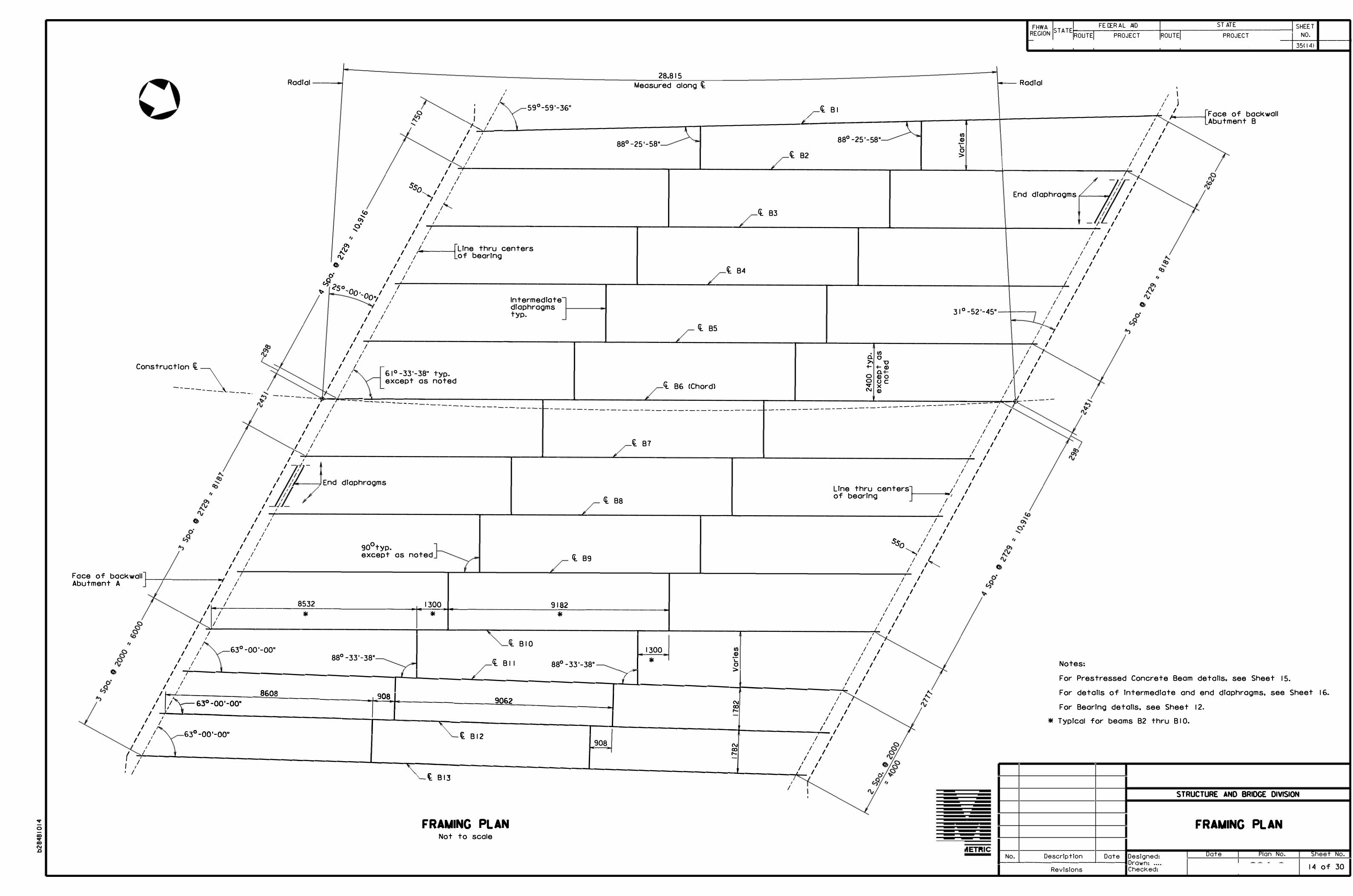
28,815 Rodi al ----o--i Measured along Ck. --- Radial
----
I
I I I
/1
59°-59'-36" Ck, Bl ,/ ) [
::::j_�' __ 1_ __________________ -r-7 ___________ ,L:__ _________
7=---r----r--___.:
1_______________ �r ,,..,.,__ __ _, Face of backwall
/ / Abutment B I
I I
/ / 88°-25'-58" :g / I I
I 88° -25'-58" ·;: / / / 0 , /
�<:::t'
11
/ i B2 > / I I
I I I
I :,,------------------------,---_._ _______ .L,.. ____________ .--__ ___,1 ____ ___,1 ___ --+-------------�I� I
I I sso
i / i
"--J1
/ End diaphragms,---� 11
I � I
I , l B3 I
/ I I
I i'----------------------,--__. _______ ......1,:..._ ___________ --, ___ ..1,_ ____________ +-_________ .,:... I
I I I I ,, I I I I
,,o, 1 1' I/ :v [Line thru centers , 1 ie: 1
1 /""•-------, of bearing / I o, / ;' I /
� B4 ' / ,.,,. I I I Qv / / , /
v5 ,?50 I "'i;,.._ ___________________ -,---L-------.L..-----------,----....L...---------------+-----./--1 I
'1- 'Oo•,oo"/1 / Intermediate / 1
1
I I I 1 / diaphragms 31o_52._45 .. ____ 1
I I typ . /
I II I
I I <l BS
I I
I I
""7;-------------------r----'-------....L..----------,------1'------.-------------+-�,I I . (I) /
I I a.o ,
I ll >- u / +-+-Cl) I
/ / 61°-33'-38" typ. 0 g-t / I , except as noted o o c ;
I I Ci. B6 (Chord) .... x N COI
I
I
I I
I
I I
I
I I
/"1'-�/,1'-=�-==-�-�-:--:::-�-=-=�-=-�---_-_--_-_----------,---..L.-------...L------------,----_J--------....L-------------=-=�-=--�'.-.Jk.-------------- -------------- I
I I -------------------------------------- ---------------- I I
I / / / I I I I
I I I I I / / /
,,
I ; � B7 , / I I I I
I �,"------------------------,,---..L.-------...L------------,---_,l------------------------/-' I
1--1- , I I
I I I
I I I I 1 �---;1 End diaphragms / ILine thru centers] 1 1
11
<t B8 of bearing ,__ - - -1
-•, 1I I I
I T--------------------,------'-------....&...------------,r-----11------------------------'�/ I
I I I I I I I I
/ / / I
// / o S,s.O / 1
1 90 typ .
/ / except as noted '----..,1 I
11
/
<l B9/ 11...._____
I I I I
Face of backwall 1------,
1--------1 , 1 I Abutment A 1 1 , 1
,,
I I I II / / /
/ I 8532 I 300 9 182 ' / I
�/-:r-----------*:------ - - - --------+---=*,::--=--i,--------------=-.:*=:..._-------------1 / I I I I
I I I I I
�l).._ _________________ +--.1...---�;--------------.---_jL-_____ .-------------+, I
I I I <l BIO , /
11
/ 63° -00 '-00" 1300 :g / / I , 88° -33'-38" *
·;: 1 I / / <l, Bl I 88°-33'-38" o / /
I I I I
Notes:
For Prestressed Concrete Beam details, see Sheet 15. 1,r-�-
�
-----
��-�-----�LJ----�
>
�---�,I1'r�/��;;=oc
N�-___!:8�6�0�---------f�t----------2Ql� _________ J , ,
I
I
908 I I ,�-63°-00'-00" SQG2 N / I I co / / /1 2:__.====�--------------t--1... ___ __,,�-=--�=------------r-t------------�
r-�-------j_/ ,
1
For details of Intermediate and end diaphragms, see Sheet 16.
For Bearing details , see Sheet 12.
I I / /
I I 63°-00'-00" r. Bl 2 / 1 1' 't. // 908 "' ' I
( ,l,._/ __ .J... _________________ L __ �::--;-�:-------------1 ____________ ��1 ____ ��// II
I ,I I I
• I / I � Bl 3
I
I
FRAMING PL AN Not to scale
* Typical for beams B2 thru BI 0.
Date Designed: 1---�-------�-----1Drawn: .....No. Description
Revisions Checked:
STRUCTURE AND BRIDGE DIVISION
FRAMING PLAN
Date Plan No. Sheet No.
14 of 30

LJFoce of bockwoll r1 Abutment A
/__ ' { End .,_ .. I�----- ---------
See Note
I Typlcol beam end
O< typ.
E O Abutment A F O Abutment B
L/2
Beam detolls symm. about mldSPon
PART PLAN
Bl1601 Computed finished grade ofter full dead load deflectlon.
Shope of top of form before any deck slob concrete Is placed. Top of form to be no where above this line.
L/4 0 b
L/4 L/4
Shope of top of form (bottom of deck slobl ofter deflectlon from I
dead load. i.--'---i------------------ L/2 ------------------� total concrete deck
� bearing If. bearing Midspan ,__ ____________ BSl301 & •BSl303 ----------------i Adjustment of deck slob forms to correct for dead load deflectlons shall be mode by varying thickness If. end diaphragm.
See Note 7 20 spa. O I SO 3000 12 SPO. 0 2S0 = 3000
50
L
Span
a
a
a
a
i--i------ L/10------i 4 - BLl601 eh min. lop 686J /
If. threaded Inserts. See Notes 4 and 7
t--+-"""T-t----i
2 - BLl601
If. 50 mm • open See Note 3
PART ELEVATION
i------1194 ------i �
__ ,}� .. J--½tl
I.
-m "' '°- �"'
Cl) ..,
Cl)
Cl) <O l'-1'-
ENO VIEW SECTION A-A
EXTERIOR BEAM
DIMENSION TABLE Beam Prestr. force No. and size of Net comber N A B
per strand strand per beam N mm mm mm
Bl 195,450 30-15.2 mm 0 46 315 88 B2 thru BIO 195,450 30-15.2 mm 0 46 315 88
Bl I & Bl2 195,450 30-15.2 mm 0 46 315 88 B13 195,450 30-15.2 mm 0 46 315 88
C mm
2740 2740 2740 2740
14 EQ. spa.
If. Intermediate diaphragm. See Note 7
1-+------+---_J
;J
prestresslng strands
BSl303
ENO VIEW
d. >, +-
I'"'
INTERIOR BEAM
BSl303
of concrete bolster between slob and beam without alteration of slob thickness. Longitudinal screed should be set above flnol finished grade by amounts = 6 C2
6 Cl = Deflection of beam from dead load of concrete deck slob, bolsters and diaphragms and does not Include the deflection of the beam from Its own weight.
6e2= Deflection of composite section from dead load
<e.g. parapet and curb added ofter deck Is costl.
6c=b.c1 + 6e2
ANTICIPATED DEAD LOAD DEFLECTION At o At b
Beam 6c1 6e2 6c1 6 e2
Bl thru BI O 28 5 21 4
Bl I thru Bl3 22 6 16 4
DEAD LOAD DEFLECTION DIAGRAM
BSl301
BLl601 See Note 9
2 spa. O SI 102
I �pa. 9� L15 typ.
L- 813__j
SECTION A-A
For dimensions not shown, see Exterior Beam
E F GI G2 mm mm mm mm
300 210 229 269 230 230 229 269 230 230 229 269 230 400 229 269
L mm
27,972 59°-59"-36" 27,547 61° -33"-38" 27,186 63°-00"-00" 27,186 63°-00"-00"
MldSPon
Expected net comber when stress transfer Is mode = N
'---------If_ storage supports--------
CAMBER DIAGRAM
Not to scale
OUTE
Notes:
STATE PROJECT
SHEET NO.
35(1!il
ll At beam ends use 25 mm deep recesses around local strand groups with 51 mm minimum edge clearances and flll with pneumatically applied mortar Immediately ofter cllpplng strands. An approved epoxy mortar covering the ends of strands with o minimum thickness of 3 mm may be used as on alternate. Strands should be cool before mortar Is applied. After mortar Is allowed to cure, the entire end of beam shall be covered with epoxy type EP-3 T.
2l For reinforcing steel. prestresslno strands and dimensions not shown In the exterior beam, see Interior beam.
3l Beams shall hove 51 mm dlo. open holes formed with non-rigid tubing only on stream crossings. Holes may be slightly shifted to clear reinforcing bars and strands.
4l Threaded Insert when embedded shall develop full strength of 22 mm dlo. threaded bolt (ASTM AJ25 Ml.
5l All prestresslng strands shall be low-relaxation with on ultimate strength equal to 1860 MPo and shall be uncoated.
6l For details of Insert plate. see sheet 12 .
7l 38 mm dlo. open holes formed with non-rigid tubing or threaded Inserts. For location of end and Intermediate diaphragms. see Erection Diagram on sheet 12. For location of holes and Inserts for end diaphragms and Intermediate diaphragms. see sheet 14 .
8l The Contractor, ofter written approval from the Engineer. may use different prestresslng strand arrangement provided that the total prestresslng force and Its e.g. ore the some as shown on the plans.
9l 2 - 12.7 mm dlo. strands stressed to 44SO N may be subtltuted for 2 - • 16 bars.
All dimensions ore shown In mllllmeters (mml unless otherwise noted. Symbol • = diameter.
REINFORCING STEEL SCHEDULE
BSl301
gL[l �I I 1086
n 343
i!!LL 9_J l--131 � 7
BSl302
rel (]]� I
L,,.. � BSl303
Mork Size No. Length Pin • BSl301 • 13 101 2300 76 BSl302 • 13 28 1575 51 BSl303 • 13 IOI 3030 51 BLl601 •16 12 14550 --
Dimensions In bending diagram ore out-to-out of bars.
Reinforcing bars shown on the above schedule ore for beams shown on this sheet only.
•BSl301 or BSl303 may be slightly shifted as directed by the Engineer to clear anchorage Inserts.
Reinforcing bars BSl301 and BSl303 shall be galvanized. All other reinforcing bars shall be epoxy coated.
PRESTRESSED CONCRETE BEAM MPCBT-13-46
No. Description Dote Designed: . 1---J_ ___ ___:. __ _,_ __ --IDrown: ·--��
Checked: .. Revisions
ate Ian No. heet No.
IS of 30

Ill Cl '<I' ;,,, '<I' +-
..... ci. (1l ;,,, U'I +-
C380 x50
Detail A
0
0
Detail B
o:
' O ''
PART TRANSVERSE SECTION
22 mm 0 bolts with hex >-+-�nut end two 57 mm 0
washers.
T hreaded Insert for 22 mm 0 x 57 bolt and 57 mm 0 washer.
i----Cf beam
DETAIL A
Use Detail A at ex terior beams and interior beams where line of diaphragms is discontinued at interior beam. Use Detail B at interior beams where line of diaphragms is continuous across the structure.
Work point O Cf beamand ITne of diaphragms
Cf beam
L 152 X 152 X 12 .7 Cf threaded insert
Line of diaphragms.
D I IL..Ai!i5:::-:Z._LSee erection pion.
8
SECTION C-C
�----1 Form 38 mm 0 holes in web with non- rigid tubing
25 X 57 slotted holes
22 mm 0 bolts with 2 hex nuts and two 57 mm 0 washers.
DETAIL B
C380 x50 --+-...,.,
Cf 27 mm 0 holesin channel
114
51
,.., Ill N
00 ,..,
CHANNEL DETAIL
Line of diaphragms. See erection pion.
Work point 9 Cf beam and line of diaphragms
It. beam
L 152 X 152 X 12 .7
8
SECTION D-D
00 ,..,
00 ,..,
Not to scale
152 152
-76- 54
I-'
" -
( , "
-
I
"
( , " - , ' ' � ,
-L 152 X 152 X 12 .7-
425 x 57 slotted hole}for 22 mm 0 bolt
BEAM FACE DIAPHRAGM FACE
CONNECTOR PLATE OE TAIL
C onstr ct Ton Joint u
-60DS l30 I\
-90
I · . . . .
' . .
.. Ii> . � • I
� . '.
.. �◄
� ◄DLl303
�� DLl902 ;tk
75 typ. -- -'"
250
SECTION A-A
Beam 8
Bl 88 °-25'-58" B2 thru BIO 90 °-00 '-00"
Bl I (Left) 88 °-33'-38" Bl I (Right) 90 °-00'-00" Bl2 & Bl3 90 O..QQ'-00"
I IJ
�
d ( , • . I
. . .
•. .
. '
. .
FHWA 1-----,----F E_D_E _R _AL_A _ID __ +----r-----S T_ A_T _E _____ ---, SHE ETREGION ST A TE
ROUTE PROJECT ROUTE PROJECT N O.
Notes:
All structural steel shall be ASTM A 709M, Grade 250 .
All bolts shall be 22 mm dlo. H. S. bolts, ASTM A325M.
All H. S. bolts shall be tensioned by the turn- of- nut method.
35( 16)
All diaphragm materials Including bolts, nuts and washers shall be galvanized.
All threaded inserts shall develop the full strength of the threaded bolts.
Payment for furnishing and Installing steel intermediate diaphragms shall be Included In the contract unit price for prestressed concrete members.
All dimensions ore shown in millimeters (mm) unless otherwise noted. Symbol 0 = diameter.
Al DS l301 *
5 Equal spa. **
-2 - DLl303
. ' . ' • •
. 0. (I)
n
0 -
• I
i= U'I ..... E (I) t.D +- I: i=
N 0II N DI: j:U'I I
N Q
N N -·-,F
II
• •
I I I L'7 ,
---------- I ----------
------------------------------ '7 ------------------- I ---------
'Y ***Y, 'T2 - DLl902 2 - DLl901
T hreaded .I 600 min. � insert typ.
�38 mm 0 openwith non- rigid
hole for med typ. tubing
END DIAPHRAGM DETAILS
END DIAPHRAGM REINFORCING TABLE
Abutment A Abutment B Location
DLl3 Serles DL 19 Serres DLl3 Serres DL 19 Serles
Between beam Bl & B2 DLl305 DLl904 DLl309 DLl908
Between beam BIO & Bl I DLl307 DLl906 DLl31 I DLl910
Between beam Bl I & Bl2 DLl307 DLl906 DLl307 DLl906
Between beam Bl2 & Bl3 DLl307 DLl906 DLl307 DLl906
* Place parallel to beams, spacing as shown ex cept use two equal spacesbetween the following:
Bl & B2 at Abutment ABIO & Bl I at Abutment A.BIi & Bl2 at both abutmentsBl2 & Bl3 at both abutments
* * Bar designation Ts DL 1303 other than noted at table.
* * * Bar designation Is DL 1902 other than noted at table.
STRUCTURE AND BRIDGE DIVISION
INTERMEDIATE & END DIAPHRAGM DETAILS
Description Date Designed: . 1---�------�----1Drawn: .... �
No. Date Plan No. -- A - -
Sheet No.
Revi sions C hecked: .. 16 of 30

0 0 "'J"
29,992 LD.29,192
SCl602 SC /603 top & bot.
top & bot. zoo 25 spa. @ 2 00
SC 1605- top & bot·52 spa. @ 2 00 = I 0,400
lop with SC 1602 = 5000
nt2r�1r������===-=���J��---=���r-::::::
-==-==-==--==--==--==----==----==�*�--==--==
-il=-
2
==
00
-==========-==-==-1
0 0 ,-.._
0 0 "1"
.!£ L 0 >
&
ES1301
End of slab Face of boelc,,oll
AEtutFFICA=t A f-----
Rodial----i
2 4° -53 '-4 I"25° 00' 00" - - -�
top & bot.
Face of sidewalk curb
, k--------ji-1-----j E S I 3 0 2 top & bot.
SC 1604 top or SC\602 bot.
29,7 28 LD. 28,815
SC l604 top or SC 1602 bot. �-.
150 x 150 - MW42 x MW42 welded wire fabric lr--+t+l-+-l,I'--.-'c
Face of median curb
,__------< Light po I e foundation
&
ES1904 - top spaced @ 150
ES1302 top & bot.
End of slab
Radial
[
R = -�000 m
--___J.-
Construction 4..
ES1303 top & bot.
ES1904 - top spaced @ 150
380 min H lap typ. J
I r 1-""I , -�-i---19 14 typ. llr--------t+--.---------"__,_-++--------.--------'....__..--------.-++------
1 00 SL l301 top & bot. SL l302
top & bot. SL l301 top & bot.
1 00
1-E------jSC l602 top or SC l602 top or >---SC l604 bot. 1_______ SC 1604 bot.
t2" p,__
�:::;�-:-:---��-------l-�--------------------JJ�tE--
--j ES I 302
0 0 "'J"
/ top & bot. t Light pole
foundation
3/5 2 00
SCl60/-top & b t 40 o .spa.@ 2 00 = 8000 SCl602 - top & bot.
25 spa. @ 200= 5000
Face of sidewalk curb
2 00
29,2 06 28,-'lOG LD.
Junction Chamber----s�
LD. See Detail ASCl602 & SCl604- top & bot.
72 spa. @ 200 = 14,400 76 spa. @ 2 00 = 15,2 00 LD.
SC I 603-top & bot.lap with SC 1602
I
I
I
I
Face of sidewalk curb
DECK SLAB PLAN Junction Chamber--�
19 mm x 45 °chomfer � --'".,.- -- End of slob
I
FHWA REGION
STA TE ROUTE
FEDERAL AID STATE SHEET >-- -- -- - - - -+----- - - - - - - - - -------<
PROJECT ROUTE PROJECT NO.
35( 1 7)
Notes:
I. For transverse section, spacing of SL series bars, median andsidewalk reinforcement, see sheet 13.
2 . SL 13 series bars shall be placed parallel to the beam, except as shown on sheet 13.
3. Transverse reinforcement shall be placed radial.
4. All transverse dimensions are radial.
5. All longitudinal dimensions are measured along edge of deck exceptas noted.
6. For deck slab elevations, see sheet 18.
& 7 . For preformed elastomeric joint details, see sheet 19.
3000
8. For aluminum railing details, see sheets 2 0, 2 1 and 2 2 .
9. For bridge conduit system, see sheet 23.
I 0. For reinforcing steel schedule, see sheet 25.
I I. For loop detector on approach slab, see sheet 28.
Face of sidewalk curb
1 Face ofmedian curb
End of slab Face of bacl<.1n•all
� ----, AbutFACA=I= 8
Construction 4..
i-----1'---- 1800 x 47 00 Loop Detector
---+- 1800 x 1800 Loop Detector
4.. 50 mm conduit
Vories Terminal/wing wall PART DECK SLAB PLAN
50
150 x 150 - MW42 x MW42 welded wire fabric
- 50 mm
Type EP 4 or EP5 epoxy typ.
, --1 k--75
MEDIAN SECTION
Not to scale
DETAIL A Detail is typical on all
four corners of slab
13 mm expanded rubber joint filler
METRIC &
No.
Extended deck slab 5/8/08
Description Date Designed: Drawn: ....
Revisions Checked:
STRUCTURE AND BRIDGE DIVISION
DECK SLAB PLAN
Date Plan No. Sheet No.
1 7 of 30

Face of Back wall 7 Abutment A J;
& End of slab -21
Point Elevation
I 320.628 2 320.576 3 320.528 4 320.'19 I
5 320.466
Notes:
/
/
,
/
2 3 4
Face of Sidewalk Curb 4 Equal spaces - -- -- --------1
�{,Ji._,:,, =�L===7 =-==�L�8 =-=�L=-9 =----+-€ftti�
I I
16
Face of Sidewalk Curb 22
23
17
Face
tl 3 I
14 /
18 19 20 of Median Curb
I
/
5
' IF ace of Back wall -------i Abutment B
2'1 25 - -End of slab &
/
PLAN OF DECK ELEVATIONS
DECK ELEVATIONSPoint Elevation Point Elevation Point Elevation Point Elevation
6 320.955 I I 32 1.05 I 16 32 I. 14 7 21 321.614 7 320.905 12 321.003 17 321.099 22 32 1.569 8 320.856 13 320.954 18 321.051 23 321.524 9 320.8 I '1 14 320.910 19 321.007 24 321 .'179
10 320. 782 15 320.877 20 320.972 25 321.437
Deck elevations shown in the table are on top of finished roadway along centerline at point of finished grade and faces of curbs.
Straight line interpolation for intermediate elevations may be made between two adjacent points at no more than 7700 mm intervals.
13 mm tooled radius
200 Min. --3�- -Porous back fill
See Drip Detail _....--150 mm 0 pipe underdrain -:---------...::;:.��
CJ'tJPCA
Slab end detail notes: I. Section is taken normal to the abutment face.2. The 13 mm expanded rubber joint filler shall extend
for the full length of the deck slab extension.3. Dimension shall be increased or decreased for every
5°C temperature drop or rise respectively by t.
Abutment t A 2 B 2
4. For details on spacing of SC series bars, seesheet 17.
5. For details on spacing of SL series bars, seetransverse section on sheet 13.
6. For details of buried approach slab, pipe underdrainand porous back fill see sheets 28, 29 and 30.
Buried approach
" , " I 00 @ 16° C " " · " · See Note 3.
slabJ
13 mm expanded rubber joint sealer. See Note 2.
Back of back wall
. I
End of slab
ES1904 spaced at 150
I
FHWA FEDERAL AID REGION STATE
ROUTE PROJECT ROUTE STATE
PROJECT
I
SHEET NO.
35( 18)
Face of Backwall 7 / /
'Face of Backwall Abutment A J-----1 ;------{Abutment B
I I
Ii. Bearing
SC series bars
SL series bars
/-+----------e--------
2
-------e------------,--
3
-------4-----.::i _
5
� /
Ii. Beam
-�-- - - - - - - - - -'1 Equal spaces - - - -- - - - - -��- Ii. Bearing
PLANShowing point of top of slab elevations
TOP OF SLAB ELEVATIONS ALONG ct BEAMSBeam I 2 3 '1 5
B l 320.586 320.524 320.475 320.444 320.432 B2 320.649 320.595 320.55 I 320.525 320.517
B3 320. 7 '18 320.693 320.6'17 320.618 320.606 B4 320.847 320. 79 I 320. 7 44 320. 71 I 320.696 B5 320.946 320.890 320.84 I 320.805 320. 787B6 321.046 320. 988 320. 938 320.900 320.878 B7 321.1'15 32 I .087 321.036 320.995 320.970 B8 32 I .244 321. 185 32 I . I 33 321.090 321.063 B9 32 I .343 321 .284 321.231 321. 186 321. 156
BIO 32 I .443 321 .382 321 .329 321.283 321.249 B 11 321.516 321 .'162 321.415 321.37'1 32 I .3'15 B l 2 32 I .589 321 .534 321.486 321.445 321.4 15 B13 321.661 32 1.607 321 .558 321.517 321.484
See Framing Plan, sheet 14, for identification of beams by number.
A
Bottom of deck slab 0 N
--t---.-End diaphragm
. . Lt---+----------< Top of backwall and bottom of slab shall be finished parallel to grade. DRIP DETAIL
d
d
�"'"�I b
d
b
.. �
d �
"'"
SL AB END DETAIL
SECTION ���
Not to Scale
METRIC & Extended deck slab 5/8/08
STRUCTURE AND BRIDGE DIVISION
DECK ELEVATIONSTOP OF SLAB ELEVATIONS
ALONG i BEAMSNo. Description Date Deslgned: Date Plan No. Sheet No.
1-- -� -- - - - -�- ----1orawn: ....
Checked: Revisions 18 of 30

cl
Curb llne
Detail A Detail D
5\ 5\ ABUTMENT PIER
PART PLAN
ICf. Joint
Detail B
. lO ·w
I----------.
. _ ----------- J. _ ---------�--------.,----1--------1
f' ' - I I
Face of Backwall
SECTION A-A
----1. - b -------· I
Do not cut above this line
PREFORMED ELAS TOMERIC JOINT SEALER In uncompressed state
�
ABUTMENT OR PIER
(SIDEWALK>
Joint & Cf. pier
Detall B
lO a \D >, - +-
Detail A at abutment Detail D at pier
Face of sidewalk curb
f' , -
. , - ',-., li.
._· : :, -.- : A
:::::::.,,' ::,1' __ ; ·:: ,,, , ,• -:')> ,
, , '"' -:-: ,-'·1.<
SECTION B-B
Curb line
200 mm R
lO
r,ri 50
SECTION C-C
13
�--++ I 00 mm R
Face of sidewalk curb
0 0 I"')
Cf. joint
6 '
6
, b
> , b
DETAIL B
6007
Cut and miter sealer. Field vulcanize
See Detoll B
, b ,
9 typ.
Preformed sealer
SECTION 0-0
225 mm R
Cf. joint
DETAIL D
Not to scale
6 ' 6 '
Mox. R = 6 typ.
0 0 I"')
DETAIL A
13
Curb line or toe of sidewalk parapet
225 mm R
Cf. joint
No.
FHWA 1-----,----FE_ D_E _R _AL_A_ID __ +----r-----S T_ A_T _E _____ ---, SHEETREGION ST A TE
ROUTE PROJECT ROUTE PROJECT NO.
35( 19)
Notes:
Section of sealer shown Is for heavy-duty structural type sealer and may vary slightly depending on manufacturer.
As nearly as possible, sides of Joints shall be straight. vertical and parallel. The area of the installation shall be free from cracks and spoils.
Sealer shall be Installed ln one continuous piece except for sidewalk areas.
Joint width W is the final Joint width of the cured concrete when placed at 16 °c. The width W shall be increased or decreased for every 5 °c temperature drop or rise respectively by t. When formed, joint width W shall be reduced by the amount � to compensate for the opening of the joint caused by the deflection of the beam when the deck concrete is placed. If the joint is formed so that the form material wlll not move and the Joint will not open as the deck concrete is placed, then adjustment � shall not be made.
Fixed Bearing: � = 4d 1::,, 'sL
Expansion Bearing: � = d �·s
L
d = Total rotation depth from top of slob to point of rotation on bearing.
L:i'.s = Deflection of beam at midspan from dead load of concrete deck slab and bolsters. (See dead load deflection diagram.)
L = Length of span.
� = Compensation for Joint opening due to deflection of beam during placement of concrete deck slob and bolsters for the last span placed adjacent to the Joint.
All dimensions ore shown in millimeters (mm) unless otherwise noted.
Abutment Pier
A
B
Sealer Sealer Joint Size Depth Width t
b h w
51 52 32 2
51 52 32 2
STRUCTURE AND BRIDGE DIVISION
PREFORMED ELAS TOMERIC
JOINT DETAILS
Date Plan No. Sheet No. Description Date Designed: 1---�------�----1Drawn: .... � 19 of 30 Revisions Checked: .

0 N
0
00... 00 N
.0
Limit of rolllng for payment on abutment
--------- 22 00--------
1B 125 7 6 I 01 .5
-- ---1 09 4- ------s� �,__-102-----i 101 .5
End of rolllng for payment on superstructure
15 0
�e----5 0
Connect 127 mm l<t, splice Joint ¢ tube to PO St
12 400 max see notes :-r- 600--i-- 600 -�
with TB I . ·•
Connect 75 mm ¢ tube 'A I--- 600 ---I to post with TB2 . E
_x
_p. Joint1 r-- I A
75 mm ¢ x 3 .1 1tube I __ tf=.========�l========ll=:I::::::;: ..... 1;......ci::i......----11..-L....-------I 1---i-----�-+------� -----.c;::l.-----l
RW13 03
Cons tr. Joint
I I
...
I I I
AW
,.
127 mm (6 x 5.6 tube
\, '
Min. lap 375 typ. 1---...... --...--.-+-.-----+---< 4 - anchor
bolts
RL 13 series
II 11
\, ,7 r- 45 0 -�
___ .... , ______ ........,m11_ .... , _____ ---I L RL 13 series L RL 13 series . .
I
95j 5 0
i----- -6_s_p _a _. _o_----i-_1 s ..... o-i---
4------"s-"---p---'---a._@---i-1._�-0 _
0--i= ��sl .� �ii·. I :
1 so = 9 00 15IB
= 6 00 300 _j5� 45 0
eq. spa. -•-?-e�q _.�sp�a-��l._ 6 _ sp��---@_15_ 0-·�L5 0
�[.!__ = 9 00
_,_s_e_;q:.,_. _ S
:..,P:.._O::,,•-i----=6--=s..e::.p-=a.c., . ...,.@=,--=I 5:....:0=---f-i
5,-...:
e:._q:,_:,•--=-SP,::_a.::.·c.__,_ = 9 00
!I !II 4 5 0 --i----- 4 5 0
..... C Cl)
0 a. OI ·-·-0 L
L 0
Typ. for all Intermediate postsRWl3 02 and 2 - RWl3 01 @ each space RGl 601 at each space--
TERMINAL WALL
----4 00 --�
121
12 4
ABUTMENTS
162 0 0 a, 0
lJ'l 0
ELEVATION
C Cl) E
0 a. Cl)
.....
-
•
0 lJ'l 0
a ·- -
'
� . , . , ., . li., ',,:. , 'A' - --
-- --•
- -38
R W13 02
RW 13 03
PIERS
0 lJ'l 0
. l! , , . A . , , ' A
'
• •
-----------------
-----------------
-----------------
l lJ'l N lJ'l
'I- OI Cl) -� L ----1----1----
.....
.§
0 lJ'l . -
-..
. a
. "
38
Top of anchor bolts
89
. fi ', -'', J
----..1--J RL I 3 series
. /', , , .
' A, , ,
. ' -'.J
RG I 60 I ---a..it.D lJ'l
. . .
SECTION A-A
0 lJ'l
·o L
L 0
.....·-E·-
0 C 0 0
0 l"l
ti} 0 u
Cl) ..... (I) L 0 C 0 0
lJ'l N
II) II) 0 u
1 0 0 l"l
' • •
' A ' - - .
- ' •
·;'.• •
-· .• '
• '' •
�
SECTION B-B
ConstructionJoint
RWl3 01
AW series
AW series
� ' A •
4 • • /j, • ' t:,,'
•
•
'
SECTION B-B
Not to scale
L------1 Cf holes
See notes.
L__ __ --1Cf bolts See notes.
©
F HWA '-----�F_E _D E_R_A_L_ A_I _D __ +--�----S_ T_A _TE _____ -----l SHE E TR EGION STA TEROUTE PROJECT ROUTE PROJECT NO.
35(2 0)
Notes:
Posts shall be seated on neoprene bearing pads I mm minimum thickness, having a nominal durometer hardness of 60. Pads shall conform to post base dimensions.
Alumlnum shims may be used for adjusting post allgnment. maximum thickness of shim build- up not to exceed 3 mm. Where more tilting of the post Is required, the concrete area shall be ground down.
Posts shall be cast alumlnum.
Roil members shall be aluminum extruded tube conforming to ASTM B221 M, alloy 6 061 -T6 or 6351 -TS only.
For mlscellaneous details, see sheet 22 .
All bevels for concrete on this sheet shall be 19 mm.
Anchor bolts may be set normal to profile grade.
B id item for railing shall include rails, rail post. bearing pads, anchor assemblles, sleeves and other associated metal parts as shown on the plans. Also included in bid item are concrete noted in plans and reinforcing steel Indicated In Reinforcing Steel Schedule.
Reinforcing bars RG 16 0 I and RW 13 0 I shall be galvanTzed. All other reinforcing bars shall be epoxy coated.
All concrete shall be Closs 3 0.
The Contractor shall determine all dimensions and details necessary for installation.
Post spacing/detailing:
Post spacing Ts measured along t. of anchor bolts.
Intermediate posts shall be equally spaced with maximum spacing not to exceed 24 00 mm.
Ralls to be continuous over o minimum of three posts before splfclng.
Termlnal walls are detailed to toke guordroTI attachment GR-FOA- I . Holes for guardrail attachment shall be formed with sleeves of 38 mm nomlnol dlo. pipe.
For mlscellaneous details CMB M R-181, see sheet 22 .
All dimensions are shown in millimeters Cmml unless otherwise noted. Symbol (II = diameter.
REINFORCING STEEL SCHEDULE
n n
7 7 t.D 0 t.D 0
0--
JlJ'l N -
RGl6 01 RWl3 02 Mark No. Size Pin 0 Length Location
*RGl 60 I •1 6 95 135 0 Curb *RL 13 II 13 - Curb
*RWl3 01 II 13 - 6 00 Terminal wall and wing *RWl3 02 • 13 7 6 226 0 Termlnal wall *RWl3 03 II 13 - 215 0 Terminal wall
*Included in payment for railing.
Dimensions Tn bending diagram ore out-to-out of bars .
D ate Designed: ---'----------'-----ID ra wn: ....
No. Descript ion
Revisions Checked:
STRUCTURE AND BRIDGE DIVISION
ALUMINUM RAILING
Date Pl an No. Sheet No.
20 of 3 0
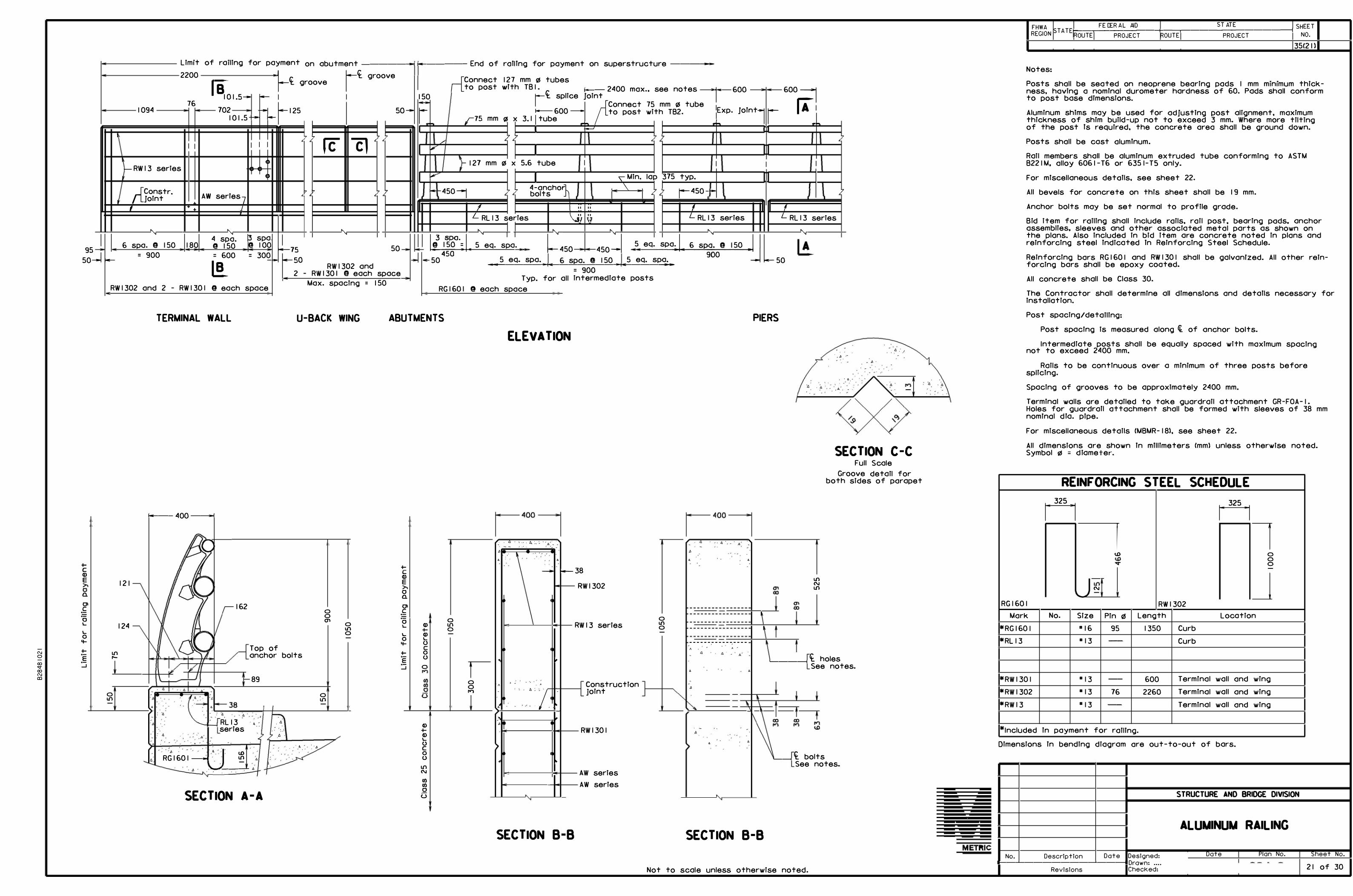
N 0-ro... roNOJ
I 95 I
50---1
+-C <D
a.
-�·oL
L 0
+-·--� ...J
Limit o f ra iling f or payment on abutment -------ii------- End of raT ITng for payment on superstructure -----2200
76 1094
I
I I
- RW 13 series
r{Constr. Joint AW
j i
t T �
• '
6 spa . CD 150 180 = 900
-
RWl302 and 2 - RWl301
• f-ct gr
18
101 .s-- - I
oove 1/f. groove
--� i--125702 101 .5 -f-
so--
I I I
I�
serles7 J
• '
� spa 4 spa. 0 150 0 100 = 600 = 300
[!_ -•
@ each space
7 '
7
'
I-15
-so
2 -
'
7 re 7
cl ' 7 '
7 7 7
'
• '
50
RWl302 and RW1301 CD each space
Max. spacing = 150
r{Connect 12 to post wl
7 mm !!I tubes th TB I . -- 2400 max.. s t ee no es 600
150 1
ct splice Joint �1· 600=1 [A1
r r75 mm QI ;{Connect 75
i------600 - to post wit x 3 .1 I tube -�
mm !!I tube 1Exp. Jolnt
7 h TB2 .
r -�I � I
l 7
/ ' 7 7 ' ' '7
I, I
� 127 mm !!I x 5 .6 tube I I I I<"' I � Min. lap 375 typ.
� -450-----J 7 ' 7 4 -ancho'J)
. \ . 7' bolts I I ' 1450 �
- i-'
I I " " , ?
L RL 13 s rles \..i, "
e L RL l3 series L RL l3 • • • •
I; �yg
a
·� I. 5 eq. spa _ s_p_o .. �+-l .,__6----'sp,_;
_0_0
_CD_l 5_0____,. I I L50 50 5 eq. spa. 6 spa. @! 150 5 eq. spa. :_j
' I I ' '
. �450 450-5 eq.
!I !I E E
'
-----------�------------= 900
Typ. for all intermediate posts RGl601 a each space
• '
--
I
I
series
7 '
7
TERMINAL WALL U-BACK WING ABUTMENTS PIERS
U'l r-
0 U'I
121
124
---400 --�
' - -.
: 4
162
Top of anchor bolts
89
��RL l3 •: series , . ,
-·', ', .. : -· ,
A.,
, '. 't,.
RGl601 --i
u:> U'I
- . , --'----+ 4
SECTION A-A
0 0 Ol
0 U'l
0 U'I 0
+-<D E
0 a.
-�·-0
L 0
+-E
...J
CD CD L u 0 u 0
u
CD +CD L u C 0 u U'l N
Cl) Cl) 0 u
0 U'l 0
I 0 0 ..,
: • '
ELEVATION
A
-- -', ,, . ',,.
A, ,,, .,
.,
- -, ,
A
- -38
• I
• I
' �
' ' A . - A
·;,. -
• ' " >
•
> • I
' "
SECTION B-B
R W1302
R W13 series
Construction joint
RWl301
A
A
W series W series
0 U'I 0
• A
----------------A
'
, •
A
, , . ,
A
A
SECTION B-B
Ll , J - -•- . -
, , t:.,-
'Ll . � , - ,A .
SECTION C-C
�----I
U'I N U'I
Full Scale Groove detail for
both sides of parapet
It holesSee notes .
�__,If. boltsSee notes.
Not to scale unless otherwise noted.
FHWA �-�F _E _D_ER_A_L_A_I D ____ -----, ____ S_T_A_T _E _____ -----; SHEETR EGION STA TEROUTE PROJECT ROUTE PROJECT NO.
35(21)
Notes:
Posts shall be seated on neoprene bearing pads I mm minimum thickness, having a nomlnol durometer hardness of 60 . Pads shall conform to post base dimensions.
Aluminum shims may be used for ad Justing post alignment, maximum thickness of shim build-up not to exceed 3 mm. Where more tilting of the post Ts required, the concrete area shall be ground down.
Posts shall be cast olumTnum.
Rail members shall be aluminum extruded tube conforming to ASTM B221 M, alloy 6061 -T6 or 6351-TS only.
For mlscellaneous detolls, see sheet 22 .
All bevels for concrete on this sheet shall be 19 mm.
Anchor bolts may be set normal to profile grade.
B id item for roiling shall include roils, roil post. bearing pods. anchor assemblies, sleeves and other associated metal parts as shown on the plans. Also included in bid item are concrete noted in plans and reinforcing steel Indicated In Reinforcing Steel Schedule.
Reinforcing bars RG 160 I and RW 130 I shall be galvanfzed. All other reinforcing bars shall be epoxy coated.
All concrete shall be Class 30 .
The Contractor shall determine all dimensions and detalls necessary for installation.
Post spacing/detailing:
Post spacing is measured along ct. of anchor bolts.
Intermediate posts shall be equally spaced with maximum spacing not to exceed 2400 mm.
Rails to be continuous over a minimum of three posts before spllclng.
Spacing of grooves to be approximately 2400 mm.
Terminal walls ore detailed to take guardrail attachment GR-FOA- I . Holes for guardrall attachment shall be formed with sleeves of 38 mm nomfnol dla. pipe.
For miscellaneous details CMB M R-18), see sheet 22 .
All dimensions are shown In mllllmeters Cmml unless otherwise noted. Symbol !!I = diameter.
REINFORCING STEEL SCHEDULE
n n
7 7 <J) 0
0 0-
--
J N-RGl601 RWl302
Mark No. Size Pin 0 Length Location
*RGl60 I •16 95 1350 Curb *RL 13 • 13 -- Curb
*RWl301 • 13 -- 600 Termfnal wall and wing
*RWl302 • 13 76 2260 Terminal wall and wing
*RWl3 • 13 -- Terminal wall and wing
*Included In payment for ralllng.
Dimensions In bending diagram ore out-to-out of bars.
Date Designed: 1---�-------�-----1Drawn: ....
No. Description
Revisions Checked:
STRUCTURE AND BRIDGE DIVISION
ALUMINUM RAILING
Date Plan No. Sheet No.
21 of 30

N N
0 a::
a) E
a) EN
0
a, lO a,
35 °
381 mm R
610 mm R
I
44 mm
' ''
67
6 -+-----i 75 j___ I 2 I ---i----
i------- 262 --
-------300------i
SIDE ELEVATION Scale = I : 4
381 mm R
10 mm R
8
mm R
See Detail B
613 mm R
19
20°
64 mm R
See Detail A
152 mm R
24
20°
64 mm R
,.,-� See DetaTI A
22
Bearing pad
a::
E E
a::
E E
... lO N
a, r-
N
--6
5
25
51
I 9 mm R -�
17 mm R
6
17.5 41 41 ---121---
i---- 203---
3
FRONT ELEVATION Scale = I : 4
1 0 -30'
6 0..,
--.-- -� ,K
//I// /
J./4-f..::,,/+-
---1 25 mm 0 + 5° draft
a::
E E
1° -30'3
SECTION A-A Scale = I : 2
16 mm !IS + 5° draft
8 mm R
45°
' '
*10 mm R
Ci:. rail
22 mm R
119 mm R
6 mm R
A
B
3 mm R
2 mm R
DETAILS A & B Full Scale
SECTION B-B Scale = I : 2
13
10 mm R typ.
33 mm r6 + 5 °
draft 4 holes
121--i
32
SECTION 0-0 Scale = I : 4
M30 X 3.5 each end i-------1 2 I -�
29 mm double chamfer heavy hex jam nut (galv.)
or washer faced heavy hex M30 X 3.5 each end
Jam nut Cgalv.)
lO lO r-- r--
t ASTM F436M. M48 washer! with neoprene washer
0 Top of concrete N ... Stainless steel rod
29 mm fin. hex nut lO X
E
U-TYPE ANCHOR BOLT ANCHOR BOLT
Two LI-Type anchor bolts may be used In place of four anchor bolts.
LI-Type anchor bolts to be set normal toface of rail.
ANCHOR BOLTS
Bolts (Rods): Conform to Section 226.02(c)4 of VDOT Specs. Threads on rods may be rolled or cut.
Nuts: ASTM A563M, Grade BS or ASTM A 194M, Grade 2H. Neoprene washer: 2 mm minimum thickness.
nomlnal durometer of 70.
0 a,
0 N ...
lO r--
FHWA FED ERAL AID STATE SHEET R EGI ON ST A TEI-R O
_U
_T
7
E ,--- P-R -0-JE_C
_T
------tR::-cO-U-=-TE::.-----PR-O-JE_C
_T ___ ------J NO .
35(22)
Notes:
All dimensions are shown In mllllmeters (mm) unless otherwise noted. Symbol 0 = diameter.
lO
M14 X 2 �----64----•
1
11111111111
-29_j
�-----75---------i
Washer &
E E
Lock washer Heavy hex nut
End of taper TOGGLE BOLT ASSEMBLY-TB I
a,
'I
Sleeve - 68 mm O.D. x 5 mm (For 75 mm tube)
Sleeve - I I 5 mm 0.D. x 8 mm (For 127 mm tube)
Exp. joint
Splice joint
Same as slab opening plus allowance for machine screw.
16
' ' ' '
--------������������������������ =======================�--------
Drill and tap M8 X 1.25
i--l •---450 ------I--'---- 450 __j
8 mm 0 x IO mm stainless steel machine screw-fllllster head
SPLICE & EXPANSION JOINT-ALUMINUM RAILS
r-73
...
R varies
\. i\:: +
�
... 17
L mm R typ.
a)
Material for toggle bolt assembly TB I shall be carbon or stainless steel having a minimum elongation of 121/.. Any non-stainless component to be either galvanized to ASTM A 153 or cadmium plated to ASTM B766.
Required minimum tensile load to equal 40.0 kN when in an open position and tested through a 25 mm !IS hole.
'Q
E E
Lock washer Washer - 16 Ga. ( 1.5 mm)
Hex nut--+--� i------83-+------+----i
-- 63--+------
MS X 1.25 �16 Ga. ( 1.5 mm)
TOGGLE BOLT ASSEMBLY-TB2
Material for toggle bolt assembly TB2 shall be steel as follows: Toggle bolt. nut. and washer ASTM A29M and toggle A569M.
All parts to be cadlum plated to ASTM B766. Required minimum tensile load to equal 4.45 kN when
in an open position and tested through a 16 mm 0 hole.
SECTION C-C i--1 •----- 261 ------i• I Scale = I : 2
N
Railing Grind smooth SHIM DETAIL
Shims to be made from 2 mm or 3 mm materlal. Shims shall not project outside of post base.
73 mm 0 x 6 mm alum. PL -75 mm tube 121 mm 0 x IO mm alum. PL -127 mm tube
I
38 --1 ( 1--- I I mm 0 drain hole
RAIL ENO CAP
Not to scale unless otherwise noted.
No.
STRUCTURE AND BRIDGE DIVISION
ALUMINUM RAILING
MISCELLANEOUS OE TAILS
D escrip tion Do te Designed: : · - - ·· {1------'Dc....acc.t..c.e_-+------'---'Pl_a n_N _o _. _____,,--_S _he_e _t _ N_ o_. --t
l---'----------'--------1 D rawn: .... : { 22 of 30 Revisions Checked: : {

n N 0
00 <T 00 N D
,---
/
FHWA REGION ST A TE
ROUTE
FEDERAL AID STATE SHEET1---,--------+--.---------------1 PROJECT ROUTE PROJECT NO.
35(23) 0 51 mm flJ nonmetallic conduit
® Nonmetallic couplingI
I 125 mm Ill opening
@ 51 mm flJ metal conduit
G) Adopter to connect nonmetallicconduit to metal conduit
® Metal expansion anddeflection fitting
® 51 mm flJ pipe cop
G) 200 x 200 x 400 formedjunction chamber
@ 25 mm flJ metal conduit
® Metal expansion fitting
(@) Pipe coupllng
@ 51 mm flJ 45° 325 mm Rsteel elbow
6 3
I
I
I
I I I I I
I
I
I
I
'
1 0 / 1 1 1 0I
I
45°
L min.
3 5
I I I I 1L I
I
I
I
ABUTMENTS
L
Curb llne
7 Ht
light pole anchorage andformed junction chamber
' • .
I
'
. '
l '
�----------------------------�----------------------------
275 mm flJ bolt clrcle --,
,,., t.l)
7 N
lOr--I
I
,------- -------. ' ' ' ' -, --I + : -1_ -----i�-----_ j� ' '' /
"-,I ',,
f ''
�'' '' '' I
\ I i
.
''.
/_ 51 mm flJ conduit , "
r--- ----------------------
r----------------------------
.....-- 25 mm !21 metal condui
? L
FL l302 I
lO N � � FL1301
� RG 1 607 t L225 225J 75- � 75
-300 300-
600
PLAN
t
3 4
250 min.
2
of slob
7
r-----1
I I ----l L __
I I __ 1_ ___ ...... ..._...,_L __
._ .................. ----
2
Detail A shown. If longitudinal movement > 20 mm, use Detail B.
CONDUIT LAYOUT
L 51 X 38 X 6.4
5
One piece 3 mm elostomeric gasket or equal
L 5 I X 38 X 6.4 ----1-
6 mm 0 x 1 00 mm stud - 2 each side
3
Drill. tap and countersink for 6 mm 0 screw, 1 2 required
I---+- PL 6 X 268CX) Ol
Bar 9 ctf typ.
5
I I I I
- _ _J L
3 4
Detail A_/ 250 1 1 8250 250
min. min. min.
'
Detoll B
PIERS PIERS For longitudinal
movement � 20 mm For longitudinal
movement> 20 mm
Typ. >--�1�1 -----,..�
�� - $ -7
'"
•----· ----------------------------------""'I,---------- ;-•--- -
• I
��I
-
7
7
i----i frame
6 mm flJ f .h. bronze or stainless steel screw typ.
.
-----------------� -----�----------------------- - -----------------:
.,..� r ' . ,, -..
' ' ' '
-
CX)
CX)
250 min.
0 0 ,,.,
1 9 � -- - I 09 - -------s-- - -1 09 - -------s�-----i i---- -_,__ 13
i-----------250-----------i
� T""T 1 1 25 mm ¢ metal conduit JUNCTION CHAMBER FRAME
CX) CX)-
•
•
-----------
----
' ' • ' ,
I 14
1
•----,[Bose plates and light polesJf----• I 1I I to be furnished by others. 1
projects 1 00 mm above concrete I
I I
�-_J1A11 r.
38 min. � ..,..,,. --Tr'TT-
--------------
. ' ' • ' ' - .--
n
- - -
'
-�----·
7
I 00 mm anchor bolt projection
FL 1302 ___ __,
FL1301
'' ''''''''''''''''''''''''
I
� '' 7I I ,,, I>
' ' b .' '' ' ' ' '
' ' ' ' ' ' ' '
: : : : - I>.,
'7 I I I I
1 50
' 0 0
-1-1------1-1-, ' I> , ------•. ' '' -!.f.::i- !.f.::i-, [>. , _i>
PL 25 X 300 X 300 with 1 50 mm (21 hole In center
25 mm ra galvanized steel drain pipe
'''''''''''' ''
i conduit and <t formed Junction chamber
Curb line
lO N
,, 0
b
1__25
, b
b r,
projection
ELEVATION SECTION A-A
RGl 607
�I I I I
I �-_J1A11..,..,,. --..,,-
38 ...... • b , . , ' ,
, b ' .
1 50 1 50
7 ICX)
,,., i--l
t
(j)
J lO -
'l uitcond
I
�� conduit for p detectors
ear Abut. B)
N -
, , , I>,'
' .0 .
loo Cn
Curb line
'7 ' ' ,.
, .i>,
,. , , b-,'
'7_,
' !> � , , , , , "_ , ,I> ,
SECTION B-B
Not to scale
Notes:
Close adherence to the manufacturer's reQuirements in regard to clearances for the Installation of deflectTon fittings shall be observed.
Junction chamber frame and cover to be galvanized. after fabrication, in accordance with AASHTO M-1 I I (AS TM A 1 23).
Cost of Bridge Conduit System and anchorages shall be included In price bid for ralllng.
Anchor bolt specifications: Nuts (Top)--- ASTM B21 IM Alloy 6262-T9 or 6061-T6.
(Bottom)--- ASTM F568 Closs 4.6. Thread series for all nuts to be ANSI B I. I 3M.
Washers--- ASTM B209M Alloy Alclod 2024-T3 or T4, 56 mm !21 x 4.2 mm. Nuts and washers of like moterlal shall be used together. Rods--- 25 mm diameter, ASTM A276, type 430 or 4 IO annealed,
hot-finished. Threads on rods may be rolled or cut 88 mm at each end of rod shall be threaded. Each rod shall be supplied with 3 washers and 3 nuts.
Longitudinal movement is the maximum amount of movement of the expansion and deflectlon fitting calculated for placement at 1 6 °cand shall be adjusted in accordance with manufacturer's requirements. The amount of movement shall be increased or decreased for every 5 °c temperature drop or rise respectlvely by t.
The Contractor shall determine all dimensions and details necessary for installation.
For location of light pole foundation, see sheet I.
For location of loop detectors, see sheet 1 7 and 28.
All dimensions ore shown in millimeters Cmml unless otherwise noted . Symbol QS = diameter.
Abutment Pier Longltudlnal t Detoll movement Type
A 5 I A
B 5 I A
When deck Is continuous over pier, expansion and deflectlon fitting detall Is not required.
REINFORCING STEEL SCHEDULE
r r lO
I 1 41
J 0
I 1 4'J r-- 0 .... lO
L typ.
Ltyp.
� 400 -I �425-I
FL l301 FL l302 Mork No. Size Pin !21 Length Location
FL l301 " 13 51 1 850 Light base FL1302 "13 51 1 950 Light base
All reinforcing steel shall be epoxy coated. Dimensions in bending diagram ore out-to-out of bars.
• Bar RC 1 60 I Cgolvonlzed) Is de tolled and accounted foron aluminum roiling sheet.
STRUCTURE AND BRIDGE DIVISION
BRIDGE CONDUIT SYSTEM
Date Designed: 1---�-------�----1 Drawn: ....
No. Description Date Plan No. Sheet No.
23 of 30 Revisions Checked:

L � N
0
MARK
AFl901 AFl902 AFl903 AFl904 AFl905 AFl906 AFl907 AF2508 AF2509 AFl910 AF25 I I AFl912 AF2513 AFl914 AFl315 AF2516 AF2517 AFl318 AFl319 AF2520
AHl301 AH 1302 AHl603 AHl604 AIII ___
"
. "
AVl301 AVl302 AVl303 AVl304
AWl301 AW 1902 AW 1303 AW 1304 AW 1305 AW 1306 AW2207 AW 1308 AW 1309 AWl310 AWl61 I AWl612
WFl301 WF2502 WFl903 WFl904 WF 1905 WF2506 WF2907
WHl301 WH 1302 WHl303 WHl304 WH 1305 WHl306 WVl301 WV 1602
AFl921 AFl922 AFl923 AFl924 AF2525 AF2526 AF2527 AFl928 AF2529 AF2930 AFl931 AFl632 AFl333 AF2534 AFl635 AFl636 AF2537 AFl938 AFl339
NO.
36 56
4 56
4 2 2 9 2 4
22 4
26 6
14 14 2
107 151
9
28 3B-28 3B-
84 7,--
157 101 IO I IO I
14 14 16 12 8 8 8
16 22 14
I I +-3-14 t-6-
39 38 24 6 8
22 98
12 12 6 6 I I
39 38
40 6 4 2 I I 7 4 8
16 56 6
196 22 22
116 155
2 2
128
REINFORCING STEEL SCHEDULE
BAR PIN DIA. LENGTH WEIGHT SIZE
mm mm kg ABUTMENT A
FOOTING
19 450 3150 253 19 450 3350 419 19 450 3950 35 19 2300 288 19 18290 164 19 11500 51 19 14130 63 25 18290 654 25 1730 14 19 1550 14 25 3100 271 19 3450 31 25 3100 320 19 3100 42 13 1000 14 25 152 2280 127 25 2300 18 13 1500 160 13 2100 315 25 14130 505 TOTAL WEIGHT IN PRECEDING GROUP OF BARS 3758
ABUTMENT A - NEAT EPOXY COATED
13 18290 509 -545-13 13300 370 -39-r-16 3000 391 16 1080 12 " -:,--- ·�- ·-- ·~- -
13 51 3190 497 13 51 3220 3919 323 -¾5-13 51 1040 1686 105 -1-68-13 2150 216
13 3780 53 19 3480 109 13 2380 38 13 3080 37 13 5230 42 13 3080 24 22 2900 71 13 5100 81 13 2850 62 13 2100 29 16 95 1750 30 � 16 95 1850 40 -4fr TOTAL WEIGHT IN PRECEDING GROUP OF BARS 3039 -3-+8+
WALL FOOTING
13 1800 70 25 152 2280 344 19 450 2350 126 19 8700 117 19 3600 64 25 8700 760 29 3600 1785 TOTAL WEIGHT IN PRECEDING GROUP OF BARS 3266
STEM -NEAT EPOXY COATED
13 8620 103 13 8450 101 13 475 TO 8620 27 13 300 TO 8450 26 13 8720 9 13 8550 8 13 2400 TO 3750 119 16 3000 TO 4300 215 TOT1L WEIGHT IN PRECEDING GROUP OF BARS 608
ABUTME NT B FOOTING
19 2600 232 19 18290 245 19 15200 136 19 14000 63 25 18290 799 25 15300 426 25 13700 218 19 3300 59 25 7600 483 29 3300 935 19 6800 91 16 2600 791 13 1300 28 25 2500 219 16 1600 288 16 2200 529 25 152 2950 23 19 1500 7 19 450 2250 643 TOTAL WEIGHT IN PRECEDING GROUP OF BARS 6216
DIMENSION
LOCATION MARK TYPE A B C D E p
mm mm mm mm mm
FOOTING AFl901 45 1450 1450 FOOTING AFl902 45 1550 1550 FOOTING AFl903 45 1850 1850 FOOTING AFl904 I 2300 FOOTING AFl905 I 18290 FOOTING AFl906 I I 1500 FOOTING AFl907 I 14130 FOOTING AF2508 I 18290 FOOTING AF2509 I 1730 FOOTING AFl910 I 1550 FOOTING AF25 I I I 3100 FOOTING AFl912 I 3450 FOOTING AF2513 I 3100 FOOTING AFl914 I 3100 FOOTING AFl315 I 1000 FOOTING AF2516 24 2000 FOOTING AF2517 I 2300 FOOTING AFl318 I 1500 FOOTING AFl319 I 2100 FOOTING AF2520 I 14130
SEAT/BACKWALL AH 130 I I 18290 SEAT/BACKWALL AH 1302 I 13300 SEAT AHl603 I 3000 SEAT AHl604 I 1080 n •---•••Al I • • I --- ' ------- . . ' ,
-
SEAT AV 1301 30 1335 1750 BACKWALL AV 1302 7 190 1887 -r+ee- 1187-ae& BACKWALL AV 1303 30 335 600 +r-4€-SEAT AV 1304 I 2150
WINGWALL AWl30 I I 3780 WINGWALL AW 1902 I 3480 WINGWALL AW 1303 I 2375 WINGWALL AW 1304 I 3080 WINGWALL AW 1305 I 5230 WINGWALL AW 1306 I 3080 WINGWALL AW2207 I 2900 WINGWALL AW 1308 I 5100 WINGWALL AW 1309 I 2850 WINGWALL AWl310 I 2100 WINGWALL AWl61 I 25 1400 WINGWALL AWl612 25 1500
FOOTING WFl301 I 1800 FOOTING WF2502 24 2000 FOOTING WFl903 45 1050 1050 FOOTING WFl904 I 8700 FOOTING WFl905 I 3600 FOOTING WF2506 I 8700 FOOTING WF2907 I 3600
STEM WH 1301 I 8620 STEM WHl302 I 8450 STEM WHl303 I VARY STEM WHl304 I VARY STEM WHl305 I 8720 STEM WH 1306 I 8550 STEM WVl30 I I VARY STEM WV 1602 I VARY
FOOTING AFl921 2600 FOOTING AFl922 18290 FOOTING AFl923 15200 FOOTING AFl924 14000 FOOTING AF2525 18290 FOOTING AF2526 15300 FOOTING AF2527 13700 FOOTING AFl928 3300 FOOTING AF2529 7600 FOOTING AF2930 3300 FOOTING AFl931 6800 FOOTING AFl632 2600 FOOTING AFl333 1300 FOOTING AF2534 2500 FOOTING AFl635 1600 FOOTING AFl636 2200 FOOTING AF2537 2 1300 841 FOOTING AFl938 I 1500 FOOTING AFl339 45 1000 1000
FHWA FEDERAL AID STATE SHEET REGIO N STATE
ROUTE I NO.
TABLE PROJECT ROUTE PROJECT
35(24)
F G H I J K L V N Q R s T u DIMENSION VARIATION TABLE
mm mm mm mm mm mm mm mm
MARK NO. I FROM TO VARY BY I FROM TO VARY BY zz zz EA. wo wo
�- �-LEN. - l/) mm mm mm - l/) mm mm mm 0 0
WHl303 I A 475 8620 1629 WHl304 I A 300 8450 1630 WVl301 I A 2400 3750 36 WVl602 I A 3000 4300 35
203
BENDING DIAGRAM
c= A t= B----,I
�
A I
G 1 t-B
L_A_J I
J Type 45 Type I Type 24 Type 30
rs-, 102 I
A
l/',9)
r 7
�
A
102 0
@ �1 D L u
J Type 7 Type 25 Type 2
127 127
203
NOTES:
Dimensions in Bending Diagram are out-to-out of bars.
1433 1650 REINFORCING STEEL SCHEDULE I
&. Extended deck slob 5/8/08
No. Des cription Dote Designed: Date Plan No. Sheet No. Drown: I
Revisions 24 OF 30 Checked: '

MARK
AHl309 AHl310 AH 1311
AHl312 AHl613 AHl614
AHl615 " , r
- �
AVl305 AV 1306 AVl307
AVl308
AWl314
AWl315 AWl916 AWl317
AWl318 AW2219 AWl320
AWl321 AWl322 AWl623
AWl624
WF 1308 WF2509 WFl910
WF191 I WFl912 WF2513
WF2914
WHl307 WH 1308 WHl309
WVl303 WVl904
SCl601
SCl602 SCl603 SCl604
SCl605 SLl301 SLl302
ESl301 ES1302
ES1303 ES1904
SW I OO ISW I 002 SWl003
SWl004 SWl005
DS 301 DL 901 DL 902
DL 303 DL 904 DL 305
DL 906 DL 307 DL 908
DL 309 DL 910 DL 31 I
NO.
3638-32�
2
2 7 7
77 .
'
163 108 108
108
14
22 22 16
9 9
22
14 42
18 -rB-
14 t-6-
20 20 18
6 6
22
52
28 12
2
20 20
82
258 z!' 104
154 +I
106 700 350
4 8
4 370
2102-E 32 16
5 5
126 176 32
96 2 6
10 30
2
6 2 6
REINFORCING STEEL
BAR PIN DIA. LENGTH SIZE
mm mm ABUTMENT B NEAT
EPOXY COATED
13 18290 13 15400 13 10000
13 8300 16 1100 16 3300
16 3000 ,
- �·
13 51 4140 13 51 3220 -364& 13 51 1040 +G8B-
13 3200
13 6500
13 4520 19 4030 13 2400
13 2500 22 2700 13 7200
13 6050 13 2100 16 95 1550
16 95 2350 TOTIL WEIGHT IN PRECEDING GROUP OF BARS
WALL FOOTING
13 1500 25 152 2780 19 450 2250
19 4900 19 3600 25 4900
29 3600 TOT, L WEIGHT IN PRECEDING GROUP OF BARS
STEM - NEAT EPOXY COATED
13 4850 13 725 TO 4200 13 76 5260
13 3150 TO 5150 19 2900 TO 4900
TOT, L WEIGHT IN PRECEDING GROUP OF BARS
SUPERSTRUCTURE
EPOXY COATED
16 1150 TO 18170
� 16 18290 16 1160 TO 10500
14- 16 11200
16 1000 TO 18130 13 9110 9572 13 11450
13 76 13030 13 76 18290
13 76 20600 19 1800
4- 10 1850 10 9110 9572 10 11400
10 2050 10 2240
TOT, L WEIGHT IN PRECEDING GROUP OF BARS
3 51 3350 9 1400 9 2400
3 2400 9 1400 3 1400
9 1650 3 1650 9 2300
3 2300 9 2450 3 2450
TOT, L WEIGHT IN PRECEDING GROUP OF BARS
SCHEDULE
WEIGHT LOCATION
kg
655 -€9-+ SEAT - BACKWALL 490 � SEAT - BACKWALL
20 SEAT - BACKWALL
17 SEAT - BACKWALL 12 SEAT 36 SEAT
359 BACKWALL ~· . ' '
..
670 SEAT 346-32-6- BACKWALL I 12 +8B- BACKWALL
344 SEAT
90 WINGWALL
99 WINGWALL 198 WINGWALL 38 WINGWALL
22 WINGWALL 74 WINGWALL
157 WINGWALL
84 WINGWALL 88 WINGWALL
43 -4B- WINGWALL
51 -5& WINGWALL 4005 +I#
30 FOOTING 221 FOOTING 90 FOOTING
66 FOOTING 48 FOOTING
428 FOOTING
947 FOOTING 1831
135 STEM 29 STEM 10 STEM
83 STEM 174 STEM
432
1229 SLAB
7324 7097 SLAB 941 SLAB
2677 1898 SLAB
1574 SLAB 6660 6360 SLAB
3983 SLAB
52 SLAB 145 SLAB
82 SLAB 1488 SLAB
218-r++ SIDEWALK 172 t-6-4- SIDEWALK
102 SIDEWALK
6 SIDEWALK 6 SIDEWALK
26659 23i'60
419 END DIAPHRAGM 551 END DIAPHRAGM 172 END DIAPHRAGM
229 END DIAPHRAGM 6 END DIAPHRAGM 8 END DIAPHRAGM
37 END DIAPHRAGM 49 END DIAPHRAGM 10 END DIAPHRAGM
14 END DIAPHRAGM I I END DIAPHRAGM
15 END DIAPHRAGM
1520
MARK
AHl309 AHl310 AH 1311
AHl312 AHl613 AHl614
AHl615 0 I --,, I ,-,
-·�
AVl305 AVl306 AVl307
AVl308
AWl314
AWl315 AWl916 AWl317
AWl318 AW2219 AWl320
AWl321 AWl322 AWl623
AW 1624
WF 1308 WF2509 WF 1910
WF 1911 WFl912 WF25 I 3
WF2914
WH 1307 WH 1308 WH 1309
WV 1303 WV 1904
SCl601
SCl602 SCl603 SCl604
SCl605 SLl301 SLl302
ESl301 ES1302
ES1303 ES1904
SW I OO ISW I 002 SWl003
SWl004 SWl005
OS 301 DL 901 DL 902
DL 303 DL 904 DL 305
DL 906 DL 307 DL 908
DL 309 DL 910 DL 311
TYPE
I I I
I I I
I
30 7
30
I
I
I I I
I I I
I I
25
25
I 24 45
I I I
I
I I
2
I I
I
I I I
I I I
2 2
2 I
I I I
I I
69 I I
I I I
I I I
I I I
A B C
mm mm mm
18290 15400 10000
8300 1100 3300
3000 �
1335 2700 190 1887 2100 335 600 li'�O
3200
6500
4520 4030 2400
2500 2700 7200
6050 2100 1200
2000
1500 2500 1000 1000
4900 3600 4900
3600
4850 VARY 5050
VARY VARY
VARY
18290 VARY
11200
VARY 9140 �572 11450
12400 17690
14400 1800
1850 9140
11400
2050 2240
450 450 138 1400 2400
2400 1400 1400
1650 1650 2300
2300 2450 2450
FHWA FEDERAL AID STATE SHEET REGION STATE
ROUTE I NO.
DIMENSION TABLE PROJECT ROUTE PROJECT
35(25)
D E F G H I J K L V N p Q R s T u DIMENSION VARIATION TABLE mm mm mm mm mm mm mm mm mm mm
MARK NO. I FROM TO VARY BY I FROM TO VARY BY zz zz EA. wo wo
::e - ::;;:-LEN. _l/) mm mm mm _l/) mm mm mm 0 0
WHl308 2 A 725 4200 695
WVl303 I A 3150 5150 105
WVl904 I A 2900 4900 105
SCl601 2 A I 150 18170 426
SCl603 4 A 1160 10500 374
SCl605 2 A 1000 18130 329
102 1187-aee-
102
BENDING DIAGRAM
t= s--, rs-, 127
GJ 1 r 7
�
A I 127
L_A_J 0
@L u
J J Type I Type 30 Type 7 Type 25
203 c=A I ' A "IA I
rA
IJ',9)fu {w t=, �1 D .. I L,cJ
Type 24 Type 45 Type 2 Type 69
95 193 210
281 570 630 311 520 600
3273 5272 6200
1230 1180 NOTES:
Dimensions in Bending Diagram are out-to-out of bars.
REINFORCING STEEL SCHEDULE II
& Extended deck slab 5/8/08
No. Des cription Date Designed: Date Plan Na. Sheet No. Drawn:
25 OF 30 Revisions Checked: ' '

"' N
a:, .... a:, N D
BH-0 ABUTMENT II A II
I STATION: 125•95 OFFSET: 5.8m rt EASTING: 3181292.6051 NORTHING: 1111148.1189SURF ACE ELEVATION: JI 7.30 m
FIELO OATADoteCsl Orlle<I: 02/25/04 - 02/25/04
S O I L R O C K DIP OrDllng hie thodlsl: Auger /Core
SPT Uethod:....I
§ ... C .. >- Other T est(sl:1/1"' z > a:: Q
§ .... a:: �z z .., ;,, C) ....
.... �� CJ ... 0 .... > C, OrDler: THO... 0 -o �
a:: z ....I ....I a:;
_,_ �:c u ..,,_ ... ;:::: <o<D .... .... :::, .. c( "' ◄< a- - Logger: THO0.. z ... a:: ....I .... a::
(3� ,- ...
.... > a.. ....I c( ◄ < c( .... a:; °'
c:, .... ::I 0.. .... "'<n a:: -... "'::I ....I "' ... ::I .. ::I a:: Uu, ,- 0 � GROUND WATER.... "' < 0 l?O 1/l .., .., < "' ..,
i:'i :c0.. N
DESCRIPTION OF STRATAu " 0.00 / 317.30
317 Clayey sond w/ cool frogments and o few sandstone cobbles.0.5
. ; -1.0 ·
316-1.5 ·
((
-2.0 · ,/; 2.00 / 315.30
315 Sands tone Boulder-2.5. 2.50 / 314.80
� . ' Clayey sond w/ freCJUent sandstone cobbles and occ. boulders.-3.0.
314-3.5. 9
◄.O313 k;
4.5
5.0 9
3125.5
6.0311
6.5' '/
7.0
I310
-7.5 ·
-8.0. p'
309-8.5.
y
-9.0.',
308 ��;• -9.5. �(
9.50 / 307.80 ��( (
Groy sondstone cobbles <Jnd clayey s�d.-10.0 10
307-10.S·
100 2011.0
30611.5 11.5
12.0305 100 80
-12.5·
-ll.0- 13
REMARKS: RIG TYPE: CUE -550. Book 12, Page 86 Hole Inside bulldlng, offset to outside.
- -
�=:-- -- -- --- -- --- -- -- -
---:=::-- -
�=:-- -- -- --- -- --- -- -- -- -
I 0.00 / 307.30 Dork groy to block, sholy slltstone,sandy streoks and cloy zones.
Bottom of hole ct 304.Jm
THE SUBSURFACE INFORt..fA TION SHOWN ON THE BORING LOGS IN THESE PLANS WAS OBTAINED WITH REASONABLE CARE AND RECORDED IN GOOD FAITH SOLELY FOR USE BY THE DEPARTMENT IN ESTABLISHING DESIGN CONTROLS FOR THE PROJECT. THE DEPARTMENT HAS NO REASON TO SUSPECT THAT SUCH INFORIJA TION IS NOT REASONABLY ACCURATE AS AN APPROXIMATE INDICATION OF THE SUBSURFACE CONDITIONS AT THE SITES WHERE THE
flssDe, some scattered thin
BORINGS WERE TAKEN. THE DEPARTMENT DOES NOT IN ANY WAY WARRANT OR GUARANTEE THAT SUCH DAT A CAN BE PROJECTED AS INDICATIVE OF CONDITIONS BEYOND THE LIIJITS OF THE BORINGS SHOWN; AND ANY SUCH PROJECTIONS BY BIDDERS ARE PURELY INTERPRETIVE AND AL TOGETHER SPECULATIVE. FURTHER THE DEPARTMENT DOES NOT IN ANY WAY GUARANTEE, EITHER EXPRESSLY OR BY IMPLICATION, THE SUFFICIENCY OF THE INFORIJA TION FOR BID PURPOSES.
THE BORING LOGS ARE MADE AVAILABLE TO BIDDERS IN ORDER THAT THEY MAY HAVE ACCESS TO SUBSURFACE DAT A IDENTICAL TO THOSE WHICH ARE POSSESSED BY THE DEPARTMENT, AND ARE NOT INTENDED AS A SUBSTITUTE FOR PERSONAL INVESTIGATION, INTERPRETATION AND JUDGMENT BY THE BIDDERS.
LAB DATA
X ....
... C ,-� a:; .... ....I >- ,-
... z c:, 0 0 5 ;:::: u a
"'::; ....
......Ia.. ,-
Cll
i5 ::E
LL Pl
PG I Cf I
BH-02 ABUTMENT HA II
STATION: 126•00 OFFSET, C/L EASTING: 3181281.3904 NORTHING: 1111148.6408SURFACE ELEVATION: 316.50 m
FIELD DATAOote<sl Orllled: 02/25/04 - 02/25/04
LAB DATAS O I L R O C K
' ..
...
..
§ :c ... 0.. UJC
"
"
"
"
•
•
"
"
•
"
•
•
•
"
•
§
�;::::<>........I....
317
.
316.
.
315.
.
314.
313
312
JI I
310.
.
309.
.
308.
.
307.
306
305.
.
....I... C ..
"'"'z > .... a:: .... ;,, C) .... a '- o .... ... a:: z ....I ....I
a:; <o<D ....a-z ... a:: ....I ............ a.. ....I... a:: ::I ::I 0.. "' ... ::I .. ::I
"' <...... 1/li:'i :c
0.8
9.0
11.3
12.0
REMARKS: RIG TYPE: CUE -550.Book 12, Poge 86
BH-06I
I ' -' - -
, BH-0�
- � � ....._ I
, I ' , I
'-- ,, Siote '- ' - ----, - --._ Creek' ---1 ' - ' I
--._ I ' ___,
I , .. .......,_ I
BH-01
>-a::....>0 u UJ a::....a::0 u
N
100
100
�z -o _,_ .....:::><a�"'<nUu,l?O
BO
100
OIP Orllllng UethodCsl: Auger /Core
..,-<a::,-"'
SPT Method:c:, Other Testis!:z .... <.:> .... Driller: THO ....I
1/l < Logger: THO... ...
a; < a: 0 ... GROUND WATER.., 1/l
DESCRIPTION OF STRATA
0.0 / 316.50 ASl)halt and Aggregote0.50 / 316.00 :,� Brown, clayey sond w/ scottere<I sandstone cobbles.
✓-
,,
J
'>
X
"t-<� 6.oo 1 31 a.so
,;: Gray sondstone cobbles w/ cloyey sand.
/
I C .. _:_ 9.00 / 307.50 C -- - Dork-gray to block, sllty, flsslle Shale, some Jointing, fragile,- -- - SC<Jttered thin 5<Jndy oreos.- -- -
- -- -
C -
C -
C -
- -- -- -C -
- -C -
- -- -
C -
C -
C -
- -
Bottom of hole Cl 304.Sm
Note: See Moteriol ond Sample Symbols List.
Legend: i'.Groundwater, initially encountered :r:Groundwater, stablllzed
RQD Rock Quollty Designation
21 15 25 SPT blow counts
.... ,- C ,-� a:; zUJ....I >- ,-
... zc:, 0 0 5 ;:::: a ::;
"' UJ.. a::....Ia.. :::,
... Cll
i5 ::E
LL Pl
PGIIJI
' ..
+c
! �
§ § �:c ;:::: ... <0.. > Ii.I 0 UJ ....I
UJ
317
.
316.
.
315.
.
JI ◄.
313
312
311
310.
.
309.
.
308.
.
307.
306
305.
.
REMARKS,
FHWA REGION STATE
BH-03
FIELD DATAS 0 I L R O C K
DIP
....I... C, <C >-"'"' z > a::.... er
�z .... ;,, C) .... ..,
o '- o .... >... 0 -o a:: z ....I ....Ia;
_,_ u .,,_ ... 0 <D .... .., :::,..,: .. "' c-z ... a:: ....I .... "' a� ... ...
.. ...... a.. ....I <a; ... a:: ::I ::I 0.. .., "'<n a::
1/l ... ::I .. ::I "' Uu, ... 0 V> <C 0 l?O V, ..,
.... .. "' u i:'i :ca.. N
0
9.1
100 95
10.7
100 100
12.1
RIG TYPE, CUE -550.
FEDERAL AID
ROUTE PROJECT ROUTE
ABUTMENT STATION: 126•05
STATE
PROJECT
II A II
OFFSET: 10m It EASTING: 3181270.2572 NORTHING: 1111148.7411SURFACE ELEVATION: 316.50 m
Dotelsl Orllled: 02/24/04 - 02/24/04
Drllllng Uethodlsl: Auger/Core
SPT Method:c:, Other Testcsi. ,-z �.... 0 ....I.... Orlller: THO ....I c:,
5 < Logger, THO a ... ::; < a::
... GROUND WATER"'
DESCRIPTION OF STRATA LL
0 I 316.50 Aggr. Concrete, Blue plostlc pipe, and sondstone cobbles
1.60 / 31�.90
�t Loose. clayey sand
2.20 I 314.30 Sondstone cobbles. clayey sand, ond scattered boulders.
::
> V
�V
1/ (/
<,
� " 6.20 I 310.30 '.
Gray. sandstone boulders. cobbles. ond clayey sand
ief
IY
-9.10 / 307,40
r ---- Dork-groy slltstone, weothered, flsslle, fractured---- 9.20 / 307.30 _-_----- Dork-groy to block, flsslle, fractured, sllty Shale. few SC<J t tere<I--
-- slderlte pebbles.------
_-_---------
_-_-----------
------_-_---------
Bottom of hole Cl 304.◄m
SHEETNO.
35(26)
LAB DATA
XUJC ,-a;
.... >- ,-... z0 0;:::: "' .... <....I a:: 0.. :::,
,-1/l
::E
Pl
Book 12, Poge 85 PAil I Cf I
BC 51-04-01 SHEET 1 OF 2
No, Description Date Data:
o---�--------�------o Drawn:
Date Plan No. Sheet No.
Not to Scale Revisions Checked: 26 of 30

... N 0 <D ... <D
BH-04 ABUTMENT
.. B
..
BH-05 ABUTMENT
STATION: 126•22 OFFSET: I Im rt STATION: 126•29 EASTING: 3181280. 7061 NORTHING: 1111173.668 EASTING: 3181267.59 SURF ACE ELEVATION: 316.90 m SURFACE ELEVATION: 317.10 m
FIELD DATA DoteCsl Drlled: 02/18/04 - 02/18/04 LAB DATA FIELD DATA
Dotetsl Drllled: 02/19/04 - 02/19/04 S O I L R O C K S O I L R O C K
.. B
..
OFFSET: C/L NORTHING: 1111174.1266
LAB DATA
FHWA REGION STATE
BH-06
FIELD DATA S O I L R O C K
FEDERAL AID
ROUTE I PROJECT ROUTE I
ABUTMENT STATION: I 26•J7.2 EASTING: 3181254.6396 SURFACE ELEVATION: 317.0 m
Dotelsl Orllled: 02/19/0◄ - 02/19/0◄
STATE
PROJECT
IIB
II
OFFSET: I Im It NORTHING: 11 I I I 73.9327
SHEET NO.
35(27)
LAB DATA
DIP DrDllng hie thodlsl: Auger /Core DIP Drllllng UethodCsh Auger /Core DIP Drllllng Uethodlsl: Auger/Core
....I
§ ... 0 .., 1/1"' z >
§ .... a:: .... ;,, C) ....
� o '"" o .... ... a:: z ....I ....I a:; :c ... ;:::: <om .... .. a-4. > z ... a:: ....I UJ ....
< < .... a.. ....I c:, .... ... a:: :::E :::E 4.
....I "' ... :::E ... :::E .... "' < .... ... "' i:'i :ca..
Jl 7 0.0 0.2
J 8 5 ' 0.65 - .
316
- . so 1.25 I .J
- . 315
- .
- . 314
- .
JIJ
312
311
310
- .
- .309
- .
- . 308
- .
9.7 - .
>-a:: �z.... >
0 -o_,_u ..,,_ .... :::>-< c( "' a:: a� ... ... .. a:; .... "'<n a::a:: Uu, ... 0
0 l?O VI .., u
N
Q z � C, � � ..-..°'-�
�c ''" \ '/
:t ;[' C/
� ._:_·:·:
. , ,.t/2 ;'.,
� 'Y
� /,
>J"/
1; % !, , 'Y,
)f t;o ;;,
�
�/ , 'Y,
7 �< (i
'f 'o
I? ;;:'., <�
·•·•• •• ·•·•• •• ·•·• ••• ·•·••••·•·
-.�- --- -
SPT Method: 8X .... ....I
Other T est(sl: ... a ,-§
... 0 .., � a:; z "'"' z > ....
§ .... a:: ....I >- ,- .... ;,, C) .... DrDler: THO � o '"" o ....... z ... c:, 0 0 a:: z ....I ....I a:; :c 5 ;:::: u ... ;:::: <om .... Logger: THO a < a-
::; "' .... 4. > z ... a:: ....I .... .., a:: L,J ... ...... a.. ....I ....I C .... ... a:: :::E :::E 4.
GROUND WATER a.. :::, ....I "' ... :::E .., :::E ,- .... "' ...1/l ....< 1/l i5 i:'i :c::E 0..
DESCRIPTION OF STRATA LL Pl
317 u 0 / 316.90 Aggregate 0.5 /r U.,u I Jlb.ru .Red dog • 1.0 ·
l 0.35 / 316.55 r 316 Light-brown, clayey sond w/ sondstone ond cool fragments.
Ir • 1.5 ·\0.85 / 316.05 Dork-brown. cloyey sond w/ cool fragments ond scattered •2.0 · 315ISOnds tone cobbles.
Jr \!;30 / 315.60
' •2.5 ·
onds tone boulder 2.10 / 31◄.80 •3.0 ·Clayey sond ond numerous sandstone cobbles, some scattered a, 314 sond zones. p
i •3.5 · e p ::,., < ◄.O 313
◄.5
5.0 312
5.5
6.0 311
6.5
7.0 310
• 7.5 ·7.◄0 I 309.50Groy. coarse groined sandstone cobbles. •8.0 · 309
•8.5 ·
•9.0 · 308
•9.5 · 9.5
9. 70 / 307.20 HO.O 307 - - Dork gray to block, sholy slltstone w/ scattered. very thin, sondy 307
- . 100
306 10.8
100
305
- . I 2.J 100
12.7 - .
75
95
100
- -- -- -
�=:-- -- -- -- -- -- -- -
- --- -- -- -- -- -
�=:--
oreas, fractured, very flsslle.
Bottom of hole O 304.2m
REMARKS: RIG TYPE, CME -550. Book 12, Poge 82
THE SUBSURFACE INFORti.fA TION SHOWN ON THE BORING LOGS IN THESE PLANS WAS OBTAINED WITH REASONABLE CARE AND RECORDED IN GOOD FAITH SOLELY FOR USE BY THE DEPARTMENT IN ESTABLISHING DESIGN CONTROLS FOR THE PROJECT. THE DEPARTMENT HAS NO REASON TO SUSPECT THAT SUCH INFORIJA TION IS NOT REASONABLY ACCURATE AS AN APPROXIMATE INDICATION OF THE SUBSURFACE CONDITIONS AT THE SITES WHERE THE BORINGS WERE TAKEN. THE DEPARTUENT DOES NOT IN ANY WAY WARRANT OR GUARANTEE THAT SUCH DAT A CAN BE PROJECTED AS INDICATIVE OF CONDITIONS BEYOND THE LIIJITS OF THE BORINGS SHOWN; AND ANY SUCH PROJECTIONS BY BIDDERS ARE PURELY INTERPRETIVE AND AL TOGETHER SPECULATIVE. FURTHER THE DEPARTMENT DOES NOT IN ANY WAY GUARANTEE, EITHER EXPRESSLY OR BY IIJPLICA TION, THE SUFFICIENCY OF THE INFORUA TION FOR BID PURPOSES.
THE BORING LOGS ARE UADE AVAILABLE TO BIDDERS IN ORDER THAT THEY MAY HAVE ACCESS TO SUBSURFACE DAT A IDENTICAL TO THOSE WHICH ARE POSSESSED BY THE DEPARTMENT, AND ARE NOT INTENDED AS A SUBSTITUTE FOR PERSONAL INVESTIGATION, INTERPRETATION AND JUDGMENT BY THE BIDDERS.
Book 12
H0.5-10.8
11.0 306
11.5
12.0 30512.3
•12.5· I 2.s
slJ.0-
REMARKS: RIG TYPE: CME -550. PGICfl Book 12, Poge 83
BH-06 I
BH-05 I
, 1 BH-04
,
•
:, ' • - •
• I
., � ---�� I '- _, Siote '- ' - --. ,---._ Cree1r1 ---1 � - -, I
BH-03 1
BH-02 BH-0 I
Not to ScoJe
>-a:: �z .... >
0 -o_,_ u .....UJ :::><a:: a�.... "'<na:: Uu, 0 l?O u
N
100 ◄O
100 90
100 100
.., ,-<a:: ,-"'
1/l ... a:;0 ..,
c:, z....<.:> .... ....I
.. ... <a:... VI
,. {,
J', ,0
�
i if
� )
� (�
//,
,[\-, b-D" Oo, D0 o o I>' oo° CY',,o D'Oo
,(y, ,o D'' OCJ, D",, o D'oonQo, o D'oooQO<o D'ooa ('::or
b D" on,D-co D Oo
,Do,
o D oo
t;� a D�~o D'Oo"C:°, o D'ooaQ'\-u D0 oo"CY,o D' un
, (o-� o D','r,,:=i 0 Go'cu D'oo°CY',o D0o-
- ··-- ··-- -- -- ,,-- ,,-- ,,-- ,,-- -- -
- -- -- ,,-- ,,-- ,,-
- -- -- ,,-- ,,-- ,,-- ,,-
Note:
SPT Method: Other Testis!: Driller: THO Logger: THO
GROUND WATER
DESCRIPTION OF STRATA 0.00 / 317.10 Light-brown. cloyey sond w/ coo ond sondstone frogments
1.60 / JIS.50 Light-brown, clayey sond w/ scattered sandstone cobbles.
2.10 I Jl ◄.◄O Clayey sand w/ scattered sondstone cobbles.
6.70 / JI 0.40 Lorge 6and6tone cobbles, numerous w/ clayey sond
8.10 I 308.◄0 Clayey sond w/ scattered groy sandstone cobbles.
9.50 / 307.60 Dark-gray, shaly siltstone, scattered fractures, very fissile.
Bottom of hole O 30◄.6m
See Moteriol ond Sample Symbols List.
Legend: i:'Groundwater, initially encountered :r:Groundwater, stablllzed
RQD Rock Quollty Designation
21 15 25 SPT blow counts
X .... ,- 0 � a:;....I >-
...c:, 0 5 ;:::: a ::; V\ .......I a..
LL Pl
PGICfl
-::5 ,-z ..,,-z0 u .., a:::::, ..."' i5 ::E
....I
§ ... 0 <
"'"'z >
§ .... a:: .... ;,, C) ....
� a '"" o .... ...a:: z ....I ....I a:; :c ... ;:::: .., om .... .. o-4. > z ... a:: ....I .... L,J ... ...... a.. ....I C UJ ... a:: :::E :::E a..
....I VI._ ::I! .., :,; UJ "' < .... < "' i:'i :ca..
317 0
. 316
-
-315
' -
-a, 31◄ p C ., -e p ::,.,..,
313
312
311
310
-
-309
-
-308
-9.5
-307
-
306 11,0
305
-12.5
-
REMARKS: RIG TYPE: CME -550. Book 12. Poge 8◄'
BC 51-04-01 SHEET 2 OF 2
= =
= =
= =
= =
= =
c:::::::J c::::::::J c:::::::J c::::::::J c:::::::; c::::::::J
>-a:: �z .., >
0 -o_,_ u .. ....... :::,..,: a:: a�.... "'<na:: Uu, 0
l?O u N
100 80
100 95
No,
<... <a:: ... 1/l
V\ ...a:;0 ..,
c:,z....0.... ....I
... ... <a:: ..."'
-~,G",C D cu ,e,:, C D co
,(y(
c: D·,
co,(y c D'
(' CJ ,(1:; c D \Cc:i"G\ (: [) Co ,G\c C co'I '
r>' �J <Y/ d) ¥ ;i:
Pc i;:::1
�' '0 Y/ 6)
� i;;; �jPc;;'. I sf l'.l'
0 Y/ oJ
� 0
;1 �/
� � �';, (
� i.
�5 � e;:i 1fo b'
�I
r":, ti> '7; t-···-I-,,,-
t-···-� -I-···-
I-,,,-
I-···-
I-,,,-
� -r -I-,,,-
t-···-I-,,,-
t-···-� -r -� -r -� --� -I-···-
I-,,,-
I-···-
I-,,,-
SPT Method: X .., Other Test(sh ,- c:,
� a:; ....I >-Drlller: THO ...c:, 0 5 ;:::: Logger: THO a ::; "'
< ....I
GROUND WATER a..
DESCRIPTION OF STRATA LL Pl "
U / .>I1.UU Light-brown, cloyey sond w/ grovel ond scottered cobbles.
2.70 / 3 I 4.JO Cobbles and clayey sand.
6.JO / 310.70llumerous. gray sandstone cobbles ond clayey sond.
9.50 / 307.50 Dork-groy, &holy slltstone, fractured, Jointed, very flsslle, scattered • very thin, sondy streaks.
Bottom of hole O 304.5m
PAlllCfl
8 ,-z .... ,-z 0 u .... a:::::, ,-"' 5 ::E
Description Date Data: Date I Plan No. Sheet No. ---�--------�-----o Drawn:
' Revisions Checked: -
' 27 of 30

'OJ N 0 OJ "' aJ N D
Right
Face of sidewalk curb
/50 typ.
6543
00 0 ·.,. D N 0a::.
0 00 ·.,. D N 0a::.
Face of median curb
6600
6600
5649
150 typ.
Face of sidewalk
Left
Face of median curb
Bock of bockwoll Abutment A Sta. I 26+00.000
Face of bockwoll Abutment A
Construction 'L
Bock of bockwoll Abutment B Sta. I 26+29.500
Rodiol-f---�
/800 X "1500 Loop Detector
(See notes)
Face of bock wall 1------,
� -- -�'"'Abutment B
1800 X 5400 Loop Detector
(See notes)
Face of sidewalk
6600 j (linel
ABUTMENT A ABUTMENT B
APPROACH SLABS LAYOUT
ESTIMATED QUANTITIES
Concrete Reinforcing spholt Co� Closs 30 Steel Type
m 3© SM-12.5A fil
kg© tric T n 1
Abutment A - Left 21.0 2585 X Abutment A - Right 29. 7 3525 / 9 ""
Abutment B 65.8 * 7660 / 19 �
Totals I 16.5 13,770 I/ 34 �
© Denotes items to be paid for on basis of pion quantities in accordance with current Road and Bridge Specifications.
* Reinforcing steel quantity includes 57 kg epoxy-coatedwelded wire fabric in median.
Scale: I = I 00
Face of median curb
5500
5132
150 typ.
Face of sidewalk curb
<(
+-c +<I) 4-E ©+---'::J .D
<(
<(
+-c +(I) .c E.�+-a::. ::J .D
<(
aJ
+c(I) E +::J.D<(
& No.
FHWA REGION
STA TE ROUTE
FEDERAL AID STATE SHEET 1-- -� -- - - - -+---�- - - - - - - - - -------i
PROJECT ROUTE PROJECT NO.
Mork AS250I AS/502 AS/603 AS/50"1 AS2508 AS/609 AS250I AS/602 AS/603 AS/605 AS2506 AS/607 AS250I AS/602 AS/610 AS 1611 AS25 l 2AS/613
35(28)
Notes:
All longitudinal dimensions ore measured along ores. unless otherwise noted.
For additional details, see sheets 29 & 30.
For loop detectors on deck slob, see sheet 17. Looi=) detectors ahall be installed in ei=,(:)raaeh ::slab By sfgnal oontraotor prior to pouring ooneroto.
* See rood plans for drop inlet (D/l location. Cut reinforcingsteel to clear DI; place cut lengths of reinforcing steeldiagonally at corners of the opening.
All dimensions ore shown in millimeters (mml unless otherwisenoted.
Sidewalk curbs, median end, median curbs and loop detectorsore to be installed on the finished roadway surface.
REINFORCING No. Size Pin 0 61 #25 31 #/6 45 #/6 "15 #/6
#2 5 #/5
83 #25 "12 #/6 "15 #/6 "15 #/6
#25 #/6
175 #25 88 #/6 90 #/6 45 #/6
#25 #/6
STEEL SCHEDULE Length Location
6450 Bottom longitudinal 6450 Top longitudinal 6100 Top and bottom transverse 3570 Top and bottom transverse 6520 Bottom longitudinal (edge) 5520 Top longitudinal <edge) 6450 Bottom longitudinal 6450 Top longitudinal 6100 Top and bottom transverse 7390 Top and bottom transverse 6370 Bottom longitudinal (edge) 6370 Top longitudinal (edge) 6450 Bottom longitudinal 6450 Top longitudinal
12,190 Top and bottom transverse 7140 Top and bottom transverse 6550 Bottom longitudinal (edgel 6550 Top longitudinal (edgel
STRUCTURE AND BRIDGE DIVISION
APPROACH SLABS LAYOUT
Changed notes 5/8/08 Description Date Designed: Date Plan No. Sheet
Drawn: ..... 28 of Revisions Checked:
No.
30

-L
0 -0) .,,. (',J
150 150 -1-----�----- Match bridge curb
�"-,��----fHTop of flnl
�
rroadway � !·
'6
0 0 OE0 -o N Cl. +-
0 ID
0 0 ASl609 top & AS2508 bottom
along edge of slob
FHWA REGION
STA TE ROUTE
FEDERAL AID STA TE SHEET >-- -� --- - - - ->---�- - - - - - - - -- ------<
Notes:
PROJECT ROUTE PROJECT NO.
35(29)
Capacity: MS 18 loading and alternate military loading. All joints that are to be sealed shall be free of cracked and spelled areas and their faoes shall be free of all foreign matter, euring eompound, oils, greases and dirt. All faees must be sand Slope to match bridge slab 0 ©+-©+- 0
Face of sidewalk curb
ASl604 top & bottom ASl604 top & bottom blasted or brushed with a meohanioal rotary wire brush. dust prior to oeoling, the joint oholl be blown out 1,tith oil free GOR9pF0550d air.
. 6
-, - - -
ASl6
"IJ L 0 ..c 0
0 +-
LO r-- L
0 :::J u
'6 C (I)
L (I)
CL
6
� L
�
series -
E Cl. 0 0 +-
+- +-0
N .J) 0 <D
0 Vl ID <( N
Vl <(
0 0
Cl. 0
+-
0 I 0
0 0 I")
©
(/) (I) 0 0 0. (/)
I") I")
N 0. 0
(Q)+-
-
1 ,,
-" 7
;1 , ;,:.
�,
0 0
� ID r--I")
, ,-' 1l,
-,
7 6 L • '
. C
{AS 160 2
,/ -L
,L:,.:-t t \
- -
� \_ AS250 I
, ' ·, ,:, -' fl , , '
SECTION A-A
b
t
b ' L
13
R = 6 mm typ.
Bond breaker
SECTION C-C
E 0
+-+-0
u I
0
©
(/)
u
0 0. (/)
<D <D
ID N
0 ID
�
0 ID 0 00
OE Oo +
© +-0
ASl605 top & bottom
"IJ L 0 s:. 0
0 Cl. +- 0
+-L 0 N
0 :::J <D 0•-"IJ Vl
C <(
(I) Cl. L (I)
CL
ID 0 .J)
Cl. E 0 0 +-+- +- )
0 0 E I
.J) 0 0 0 +- I +- 0 0 0 0
Left Approach Slab .J) I") 0 ID (Q)
0 ID (/) © N (I) Vl 0 (/) <( 0
Cl. u(/) 0
ASl603 top & Cl. N (/)
N ,q-
( 0 OE 0 Oo 0 N Cl.
0 +- ID
©+- @+- r--0
t t ,q- oo.D
ASl603 top & bottom Face of median curb
0 f LO 0
LO
100 ASl603 & ASl604@ 450 c-c top
100 300 ASl603 & ASl604@ 2 25 c-c bottom 250
6600 * Chord at face of median curb
6600 * Chord at face of median curb
300 ASl603 & ASl605@ 450 c-c top 250 ASl603 & ASl605@ 2 25 c-c bottom
1A
Face of median curb
ASl603 top & bottom
) ASl603 top & bottom
Right Approach Slab
ASl605 top &
(
Face of sidewalk curb
Face of backwall
Back of backwall
300 min.
Slope
150 mm 0 pipe underdrain
,q- oc, .J)
���--1=
tE::::::::::::�::=�=======�=============��
3/4" x ¾" mesh. min. 17 ga. <galvanized after weaving) hardware cloth. Crimp around outlet end and secure with galvanized stool wire. Cost of hardware cloth shall be included in the bid price for Pipe Underdrain, I 50 mm.
0 ID
0 0
ASl607 top & AS2506 bottom I Aalong edge of slab �
PLAN
PIPE UNDERDRAIN END
&
Not to scale
DETAIL
E :::J E ·-
C·-
E
0 ID
r
Deformed reinforcing bars shall conform to ASTM A6 I 5M, and shall have a yield strength of 4 20 MPa. All reinforcing bar dimensions except for bending diagram are to centers of bars.
Face of back wall
The cost for the aggregate material below the approach slab and including the 1500 mm extension will be included in the price bid for concrete for the approach slob and no additional compensation will be allowed.
Back of backwall
15007
Structural approach slabs are not included in the bridge contract. Prime aggregate base material with 1.8 liters per m 2• Liquid Asphalt Material Type RC-70, RC-250 or MC-250 if aggregate base is exposed for more than 2 weeks.
* Spacings for reinforcing steel bars are parallel and perpendicular tothe longitudinal chord at the face of median curb unless otherwisenoted.For layout geometry of median barrier, see the road plans.For estimated quantities and reinforcing steel schedule, see sheet 28.All dimensions are shown in millimeters (mml unless otherwise noted.Symbol !Zl = diameter.Pipe underdrain shall conform to the requirements of Section 23 2.The pipe underdrain shall follow the cross slope of the roadway overthe approach slab. The pipe underdrain shall extend to 300 mm past theedge of the side slope and be located to provide free drainage awayfrom the structure. The slope towards the side slopes shall be no lessthan two percent (21/.l. Porous back ffll shall be placed around the pipeunderdrain as detailed and as directed by the Engineer. The porousbackfill shall extend 300 mm off the end of the deck extension overthe buried approach slab and then 450 mm off the end of the deckextension to the outside edge of wings. The porous back fill shall bepaid for as Porous Backfill when it is a bid item and when porousbackfill is not a bid item it shall be included in the bid price for theburied approach slab. The bid price shall be full compensation for alllabor, tools, materlals, equipment, and Incl dentals required for thesatisfactory completion of the work.
Porous back fill slab
ASl60 2 0 0 0 ID
,q-
i t ' 6
�
LO r--I")
t �
0 0
,
6 /2 '
' 6
', r Face of bockwoll
LD oc,
AS2501 ID 75 Aggregate base material Type I , size no. 2 I B
Bolster as necessary
METRIC
No.
SECTION B-B
Changed to buried 5/8/08
STRUCTURE AND BRIDGE DIVISION
APPROACH SLABS BURIED ABUTMENT A
Description Date Designed: Date Plan No.
1-- -� -- - - - - - -�- --.1 Drawn: ..... .
Sheet No.
Revisions Checked: ........... . 29 of 30
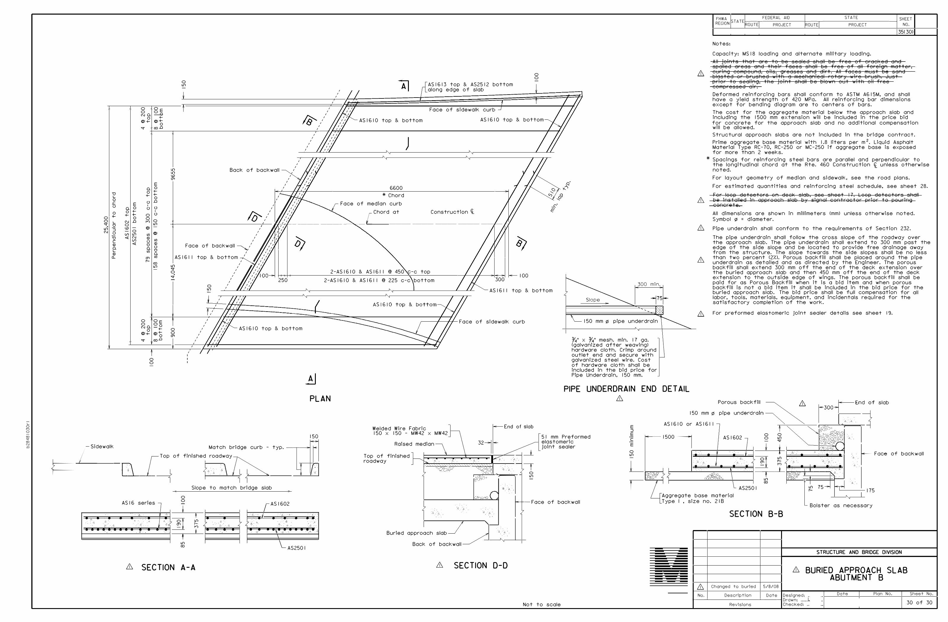
L 0n000 -scr-00 N .0
DL 0.L0
00 +-0 L s:r 0. L{] :::JN 0·-
D
Q) Q L Q) o_
L
dewalk
�--
,. '1 "
" .
E Q 00 +-
+- +-0
N .00<.D
0
\/) L{]
<! N
V1 <!
00 N Q
0 @+-
Q 0
+-
0I 0
00I")
@
Cf)
Q)
00Q Cf)
a,r--
0 0 NO.
0@+-
s:r
OE 0 0 +@ +-
0O'.) .0
E0
+-+-0.0
0I 0
0L{]
Cf)
Q)
0 0 QCf)
co L{]
OE Oo
+-@+-
0roD
00
0L{]
' '
'
' '
' ASl613 top & AS2512 bottom along edge of slab
Face of sidewalk curb
00
ASl610 top & bottom ASl610 top & bottom
Bock of bockwall ,
I
I I
ID',/
' I
' '
' I
'
' '
I
' '
'
'
6600 * Chord
Face of median curb
)
Construction l./'::-..... ,{
Chord at
-+- --------------�,'- u-,---:---,-,-- ---- ---- - �,,___- ---- ---- ---- ---- ---1--
Face of backwall �,'I
AS 1611 top & bottom ' I
L{] I
I s:r ' 0 I
s:r I
' I
0 I
I
I
' I
I '
2-ASl610 & ASl61 I @ 450 c-c top250 2-ASl610 & ASl61 I @ 225 c-c bottom 300
100 300 min.
FHWA REGION
STA TE ROUTE
FEDERAL AID STA TE SHEET>-- -� --- - - - ->---�- - - - - - - - -- ------< PROJECT ROUTE PROJECT NO.
35(30 )
Notes:
Capacity: MS 18 loading and alternate military loading. All jeiA=l=.s tt=ia=I= are =l=e Be sealed sl=.all lse f1-ee ef eraelteel aAeJ spelled areas and their =faces shell be =free of all =foreign ffiottcr, eurin§ eeffl13eunel, eils, �reases anel elirt. All faces must Bo sane! blasted or brushed with a FReehanieal rotary wire brush. dust i:,rior to scalin'§, the joint shall l:>e l:>le•,,n out •,,ith oil free COfflpressed eir.
Deformed reinforcing bars shall conform to ASTM A6 I 5 M, and shall have o yield strength of 420 MPo. All reinforcing bar dimensions except for bending diagram are to centers of bars. The cost for the aggregate material below the approach slab and including the 1500 mm extension will be included in the price bid for concrete for the approach slab and no additional compensation will be allowed. Structural approach slabs are not included in the bridge contract. Prime aggregate base material with 1 .8 liters per m 2• Liquid Asphalt Material Type RC- 70 , RC-250 or MC-250 if aggregate base is exposed for more than 2 weeks.
* Spacings for reinforcing steel bars are parallel and perpendicular tothe longitudinal chord at the Rte. 460 Construction It unless otherwisenoted.
For layout geometry of median and sidewalk, see the road plans. For estimated quantities and reinforcing steel schedule, see sheet 28.
l="or loop deteetoro on deal< slab, see sheet 17. Loop detectors shall 1;Je1 inatgll@d in gpprggch algb by eigngl c0ntrgctor prior tg pgyring cGncr<etfg
All dimensions ore shown in millimeters (mm) unless otherwise noted. Symbol !ZI = diameter.
& Pipe underdrain shall conform to the requirements of Section 232 .
U1 ASl61 I top & bottom
The pipe underdroin shall follow the cross slope of the roadway over the approach slab. The pipe underdrain shall extend to 300 mm past the edge of the side slope and be located to provide free drainage away from the structure. The slope towards the side slopes shall be no less than two percent (21/.l. Porous back fill shall be placed around the pipe underdrain as detailed and as directed by the Engineer. The porous backfill shall extend 300 mm off the end of the deck extension over the buried approach slab and then 450 mm off the end of the deck extension to the outside edge of wings. The porous back fill shall be paid for as Porous Back fill when it is a bid item and when porous backfill is not a bid item it shall be included in the bid price for the buried approach slob. The bid price shall be full compensation for all labor, tools, materials, equipment, and incidentals required for the satisfactory completion of the work.
00a,
' I
I
' I
' I
' I
I '
J ,'
Face of sidewalk curb ASl610 top & bottom
PLAN
Welded Wire Fabric End of slab
150 150 x 150 - MW42 x MW42
Raised median
Slope
' ' For preformed elastomerlc Joint sealer detalls see sheet 19. 150 mm i;; pipe underdroin
3/'4" x ¾" mesh. min. 17 go. (galvanized after weaving) hardware cloth. Crimp around outlet end and secure with galvanized steel wire. Cost of hardware cloth shall be included in the bid price for Pipe Underdrain, 150 mm.
PIPE UNDERDRAIN END DETAIL
& Porous bock fill
E :::J E C
ASl610
150 mm 0 pipe
AS 161 I or -
5 I mm Preformed elostomeric joint sealer
•-E
i------15 00
7 ASl602 7
00
0L{] s:r
slob
Match bridge curb - typ. -�-...i r Top of finished roadway Top of finished
0L{]
-· - ,_,,<l
t L{]
', r Foce of bockwoll
0......--''---..,__
G -- ,' D
Slope to match bridge slab
ASl6 series
6
. ' " 4 .
/j
-
6
"· .. · 76 ,,
00
f U1co
& SECTION A-A
7 1 b
.
r ASl602
- ,'6, - ,I � . , d.', ,- ::, -
" "
/ 'j L ' 1 "
/\- \ 1 .
\
\_ AS2501
roadway
'. : ,,: , .
1
' .1
n.. .0
--+--Face of backwoll
Buried approach slab
Bock of bockwall
SECTION D-D
Not to scale
r
7 -!� ' L . 6 ' - - - .. ·-·
r-- L
I ·,", ' '
.,7 ·rl'c
d-:fzSb60c
ft - ' ."'' t . L
-�t -�- h,,..,,,,,
,'n,+,-'----,.: 6 •
IL AS2501
L{] O'.)
Aggregate base material Type I • size no. 2 I B
SECTION B-B
& Changed to buried 5/8/08
No. Description
L{] 75r--
Bolster as necessary
STRUCTURE AND BRIDGE DIVISION
& BURIED APPROACH SLAB ABUTMENT B
Date Plan No. Sheet No. Date Designed: . 0---�- - - - - - - -�- --.1 Drawn: ..... l
Revisions Checked: .. 30 of 30


![DESIGN EQUATIONS FOR EMBEDMENT …newbuildscanada.ca/wp-content/uploads/2010/11/wcte-2014_PAP716... · Embedment tests were performed in accordance with ASTM D5764 [12] half-hole](https://static.fdocuments.us/doc/165x107/5b701f667f8b9af12d8d2d2e/design-equations-for-embedment-embedment-tests-were-performed-in-accordance.jpg)

