PRV Sizing Selection Application Guidelines -...
72
PRV Sizing, Selection & PRV Sizing, Selection & Application Guidelines Application Guidelines 1
Transcript of PRV Sizing Selection Application Guidelines -...
PRV Sizing, Selection & PRV Sizing, Selection & Application GuidelinesApplication Guidelines
1
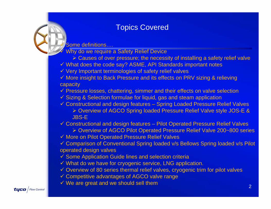
Topics Covered
Some definitions….Why do we require a Safety Relief Device
Causes of over pressure; the necessity of installing a safety relief valveWhat does the code say? ASME, API Standards important notes Very Important terminologies of safety relief valves More insight to Back Pressure and its effects on PRV sizing & relieving capacity Pressure losses, chattering, simmer and their effects on valve selection Sizing & Selection formulae for liquid, gas and steam application Constructional and design features – Spring Loaded Pressure Relief Valves
Overview of AGCO Spring loaded Pressure Relief Valve style JOS-E & JBS-E
Constructional and design features – Pilot Operated Pressure Relief Valves Overview of AGCO Pilot Operated Pressure Relief Valve 200~800 series
More on Pilot Operated Pressure Relief Valves Comparison of Conventional Spring loaded v/s Bellows Spring loaded v/s Pilot operated design valves Some Application Guide lines and selection criteriaWhat do we have for cryogenic service, LNG application. Overview of 80 series thermal relief valves, cryogenic trim for pilot valves Competitive advantages of AGCO valve rangeWe are great and we should sell them 2
3
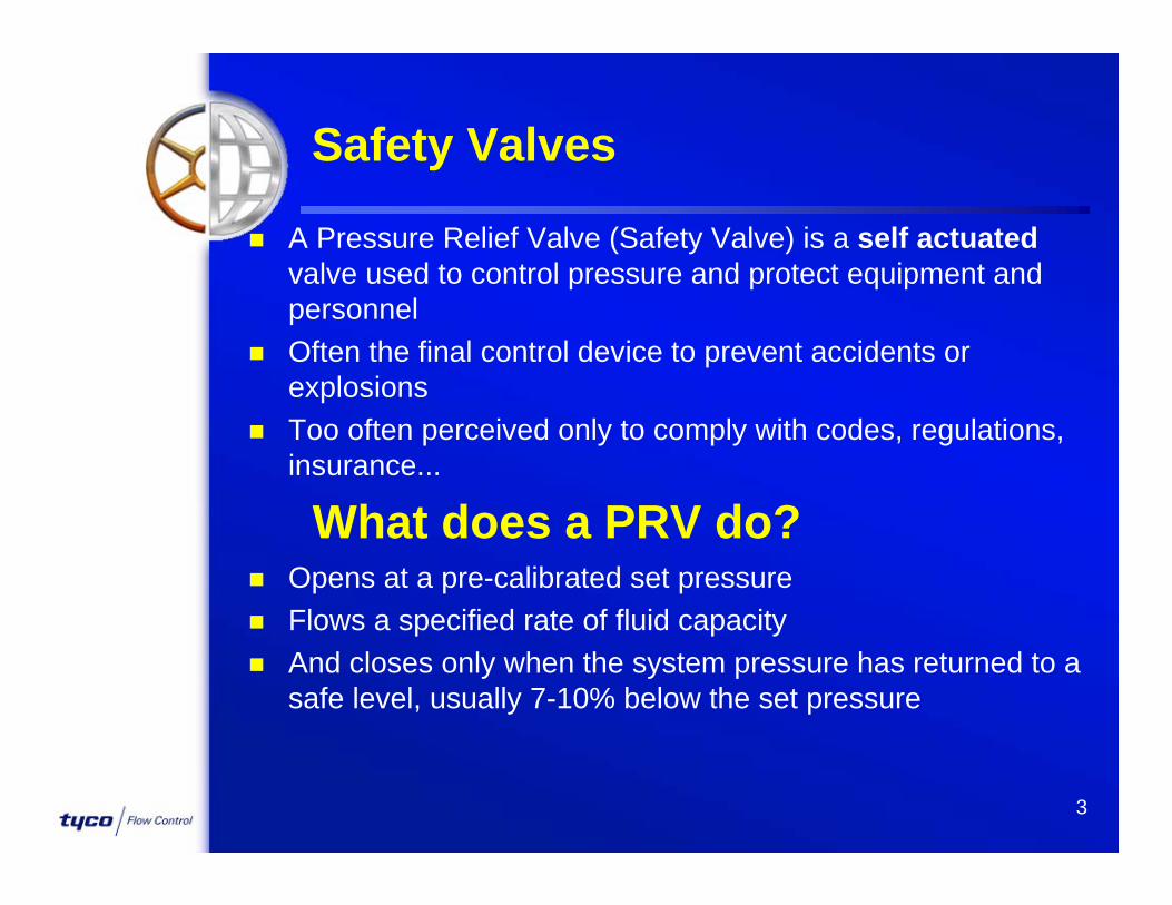
A Pressure Relief Valve (Safety Valve) is a self actuatedvalve used to control pressure and protect equipment and personnel
Often the final control device to prevent accidents or explosions
Too often perceived only to comply with codes, regulations, insurance...
Safety Valves
What does a PRV do? Opens at a pre-calibrated set pressure Flows a specified rate of fluid capacity And closes only when the system pressure has returned to a
safe level, usually 7-10% below the set pressure

4
Most Common Causes of Overpressure
Blocked DischargeThermal ExpansionExposure to External FireFailure of any Equipment such asa Control Valve or an Exchanger Tube
Must consider the one worst case while sizing a PRD

5
Blocked Discharge
FULL INPUT FLOWFULL INPUT FLOWFULL INPUT FLOW
(FROM COMPRESSOROR PUMP)
(FROM COMPRESSOR(FROM COMPRESSOROR PUMP)OR PUMP)
PRDPRDPRD
PressurePressureVesselVessel
OUTLET BLOCKVALVE CLOSED

6
PRDPRD
STORAGE ORSTORAGE ORPROCESS VESSELPROCESS VESSEL
External Fire

7
PRDPRDPRD
LIQUID FULL PIPE OR LIQUID FULL PIPE OR PRESSURE VESSELPRESSURE VESSEL
Thermal Expansion
8
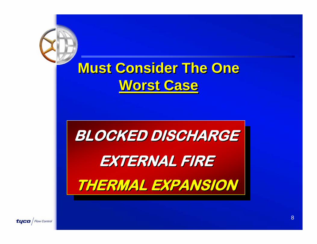
BLOCKED DISCHARGEBLOCKED DISCHARGE
EXTERNAL FIREEXTERNAL FIRE
THERMAL EXPANSIONTHERMAL EXPANSION
Must Consider The OneWorst Case
Must Consider The OneWorst Case

9
Safety ValveProtected System
Maximum Allowable Pressure
(Design Pressure...)
Reseat Pressure
Blowdown (usually 5-7%)
Overpressure
(Full) Opening Pressure
Set Pressure
(Tight) Shut-Off PressureOperating Pressure(service pressure
The “money-maker”)
Accumulation(usually 10%,
depends on code)
Where the SV is normally sized
Pressures

10
Back-Pressure...
Constant Back-Pressure valve discharge into a
system at a constant pressure
pump suction, steam tank, ...
11
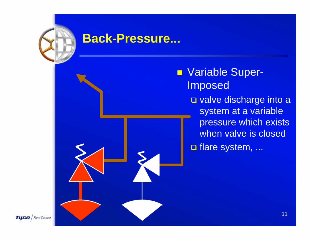
Back-Pressure...
Variable Super-Imposed valve discharge into a
system at a variable pressure which exists when valve is closed
flare system, ...

12
Back-Pressure...
Variable Built-Up exits only when valve is
flowing created by the flow from
the valve always, and increases
with exhaust piping accidents
13
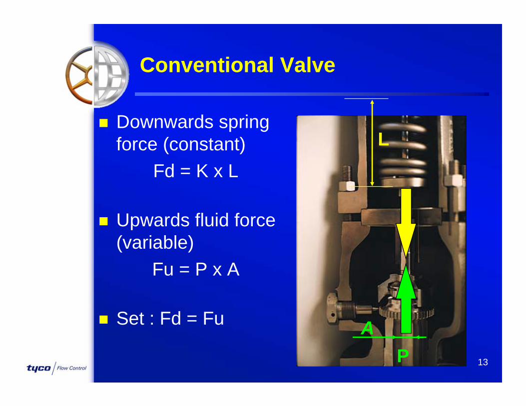
Conventional Valve
Downwards spring force (constant)
Fd = K x L
Upwards fluid force (variable)
Fu = P x A
Set : Fd = Fu AP
L
14
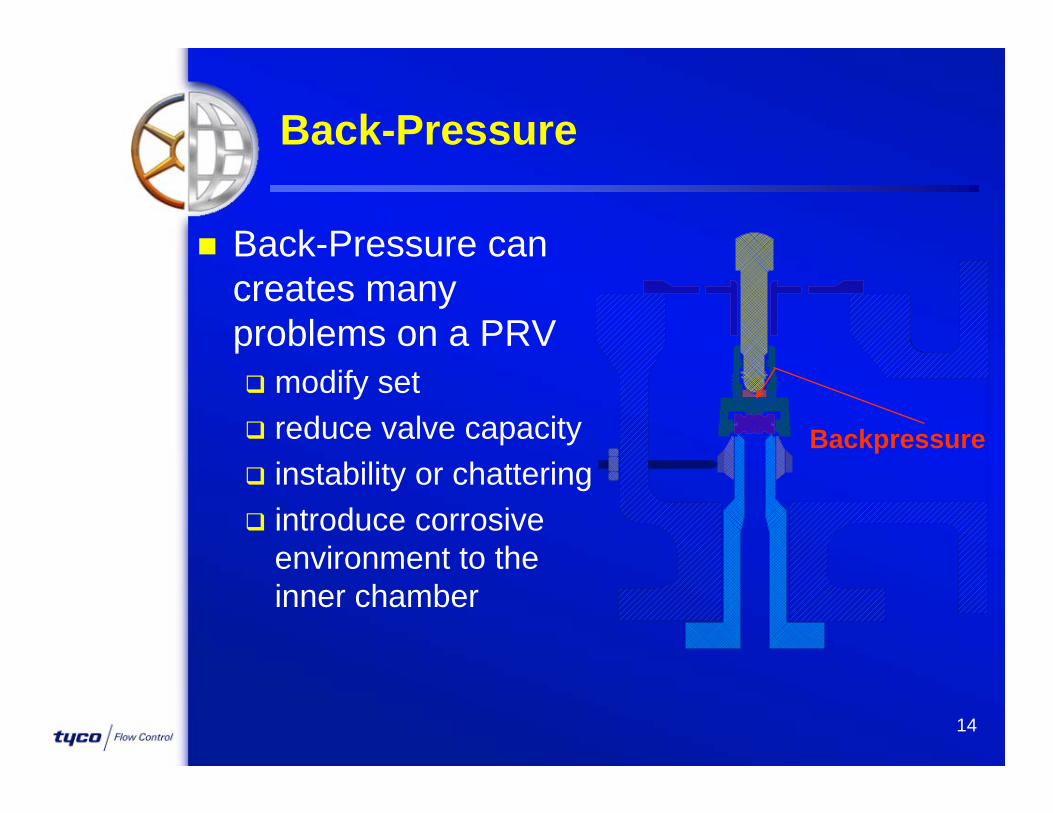
Back-Pressure
Back-Pressure can creates many problems on a PRV modify set reduce valve capacity instability or chattering introduce corrosive
environment to the inner chamber
Backpressure

15
Backpressure on Conventional valves
Conventional Unbalanced Backpressure acts
on top of the Disc Holder Set pressure varies
one for one withbackpressure
BP

16
Backpressure on Conventional valves
Constant Backpressureactual set = bench set + backpressure
required set: 10 barsconstant backpressure: 2 barsbench set = 10 - 2 = 8 bars
Variable BackpressureSuper-imposed = set point will vary with
back-pressureBuilt-up = acceptable up to 10% of set
17
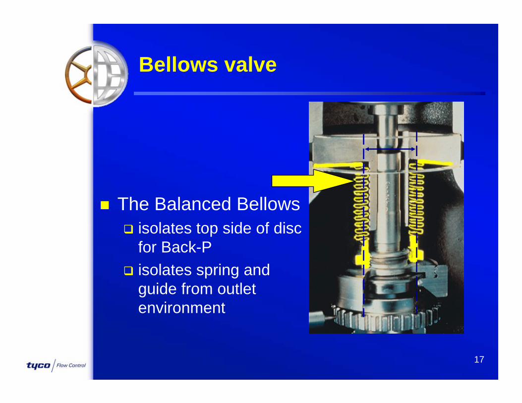
Bellows valve
The Balanced Bellows isolates top side of disc
for Back-P isolates spring and
guide from outlet environment

18
50%
60%
70%
80%
90%
100%
0% 20% 40% 60% 80%
Built-Up Back Pressure in % of SET Pressure
%R
ated
Lift
ConventionalSpring Valve
BalancedSpring Valve
Lift vs Built-Up Back Pressure

ASME Boiler and Pressure Vessel Code
Developed in 1914 to address boiler explosions in the U.S.
Five book sections deal specifically with Pressure Vessel Design & Equipment
What does the code say? ASME, API Standards
ASME Sec I : power boilers ASME Sec II : materials to use ASME Sec V : NDE ASME Sec VIII : Construction of pressure vessels ASME Sec IX : welding, brazing

ASME Boiler and Pressure Vessel Code Section I Power Boilers - “V” Stamp.
Addresses Steam Boiler applications only Safety Valve must attain full lift, discharging
its rated capacity at 3 % overpressure. Valve must close at 96 % of its stamped set
pressure (4 % Blowdown maximum). Lifting Lever mandatory to manually lift the
Disc off the nozzle seat for testing purposes
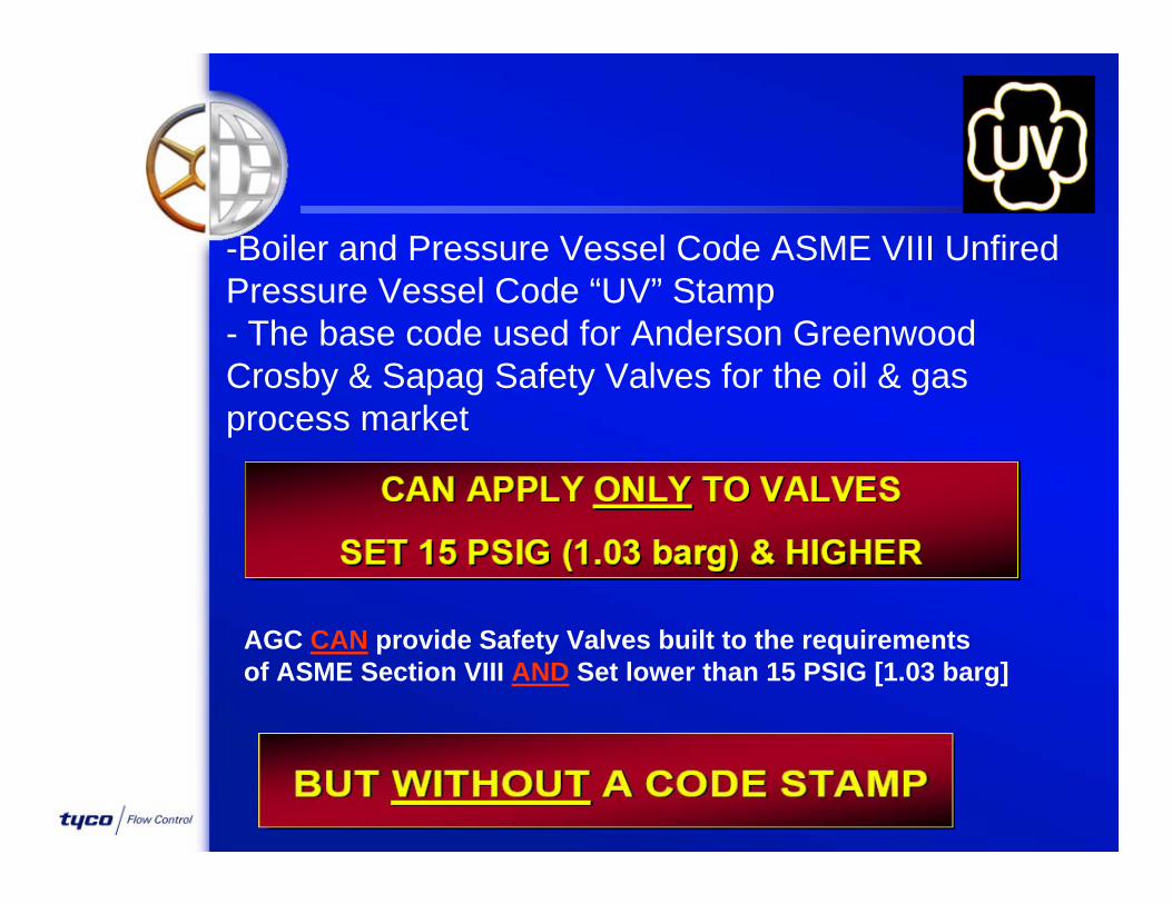
-Boiler and Pressure Vessel Code ASME VIII Unfired Pressure Vessel Code “UV” Stamp- The base code used for Anderson Greenwood Crosby & Sapag Safety Valves for the oil & gas process market
AGC CAN provide Safety Valves built to the requirementsof ASME Section VIII AND Set lower than 15 PSIG [1.03 barg]

THE NATIONAL BOARD CERTIFIES VALVE CAPACITY AND VERIFIES VALVE COMPLIANCE WITH THE ASME CODE
ASME VIII Unfired Pressure Vessel Code Basic Requirements
Pressure Relief Devices must prevent the pressure from rising more than 10% (or 3psi, whichever is greater) above the highest set pressure that any relief device is set, but in no event more than 16% above the MAWP.
(to be continued in next page…)

If an additional hazard can be created by exposure of the vessel to a fire, relief devices must be capable of preventing the pressure from rising more than 21% above MAWP Single Safety Valve as overpressure protection must be set at or below the MAWP Multiple Safety Valves Installation
o One Safety Valve set at or below MAWPo Balance may be staggered, set with the highest being no more than 105% of MAWP
Blowdown (reseat) is not addressed by Section VIII for production valves, therefore blowdown testing is not performed at the factory Depending on process fluid and valve type, blowdown can vary from five to twenty percent

Part UG – General Requirements : UG–126 Set Pressure
Set pressure tolerance:-Up to 70 PSIG (4.8 bar) : ± 2 PSIG (0.14 bar) Above 70 PSIG : ± 3%
UG–136 Minimum Requirements for Pressure Relief Valves
Valves on air, water over 140F, or steam require a lifting device:-Spring Operated valve: Lifting Lever Pilot Operated valve: Lifting Lever, Push Button or Field Test Con Cast iron seats and discs not permitted Springs must be of corrosion resistant material or have a corrosion resistant coating

API Standard 526 Flanged Steel Safety Relief Valves
An industry standard which covers:- Orifice Designation and Effective Area (D to T) Valve Size and Rating, Inlet x Outlet Material Requirements - Body and Spring Pressure and Temperature Limits Center-to-Face Dimensions, inlet and outlet
API Standard 527 Seat Tightness of Pressure Relief Valves
Methods for determining seat tightness for metal & soft seated PRVs Test Methods: air, steam and water Acceptance Criteria Soft Seated Valves: no leakage
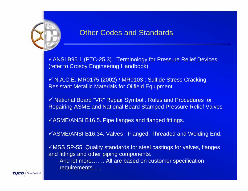
Other Codes and Standards
ANSI B95.1 (PTC-25.3) : Terminology for Pressure Relief Devices (refer to Crosby Engineering Handbook)
N.A.C.E. MR0175 (2002) / MR0103 : Sulfide Stress Cracking Resistant Metallic Materials for Oilfield Equipment
National Board “VR” Repair Symbol : Rules and Procedures for Repairing ASME and National Board Stamped Pressure Relief Valves
ASME/ANSI B16.5. Pipe flanges and flanged fittings.
ASME/ANSI B16.34. Valves - Flanged, Threaded and Welding End.
MSS SP-55. Quality standards for steel castings for valves, flanges and fittings and other piping components.
And lot more……. All are based on customer specification requirements…..

27
MAWPMAWP
(MAX. SET)(MAX. SET)
ONE VALVE ONLYONE VALVE ONLY
ONEONE
PRDPRD
10%10%
OR 3 PSIG,OR 3 PSIG,[0.20 BARG][0.20 BARG]WHICHEVERWHICHEVERIS GREATERIS GREATER
110110
100100
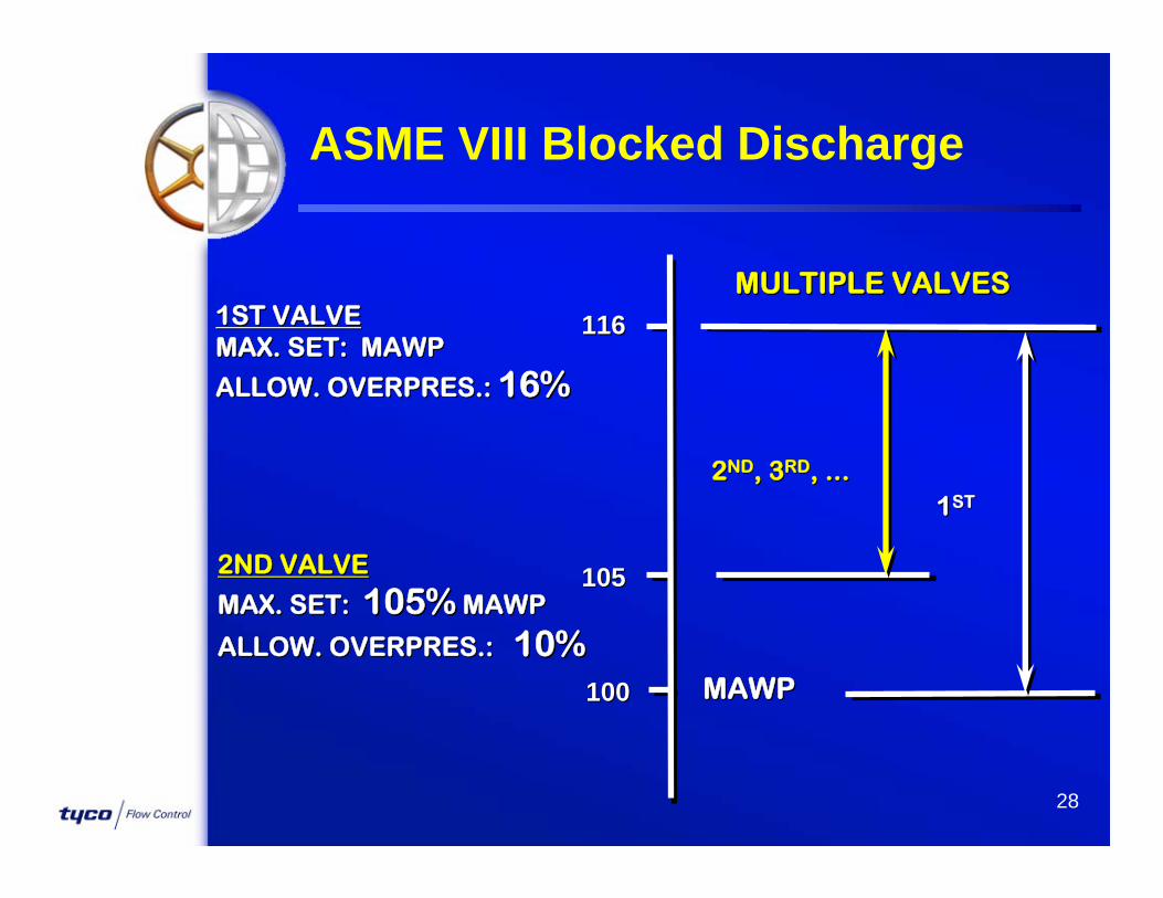
ASME VIII, Blocked Discharge
ALLOWABLE ALLOWABLE OVERPRESSURE:OVERPRESSURE:
28
1ST VALVE1ST VALVEMAX. SET: MAWPMAX. SET: MAWP
ALLOW. OVERPRES.: ALLOW. OVERPRES.: 16%16%
MULTIPLE VALVESMULTIPLE VALVES
MAWPMAWP
116116
105105
100100
22NDND, 3, 3RDRD, ..., ...
2ND VALVE2ND VALVE
MAX. SET: MAX. SET: 105%105% MAWPMAWP
ALLOW. OVERPRES.: ALLOW. OVERPRES.: 10%10%
11STST
ASME VIII Blocked Discharge

29
1 VALVE1 VALVE
ALLOW. OVERPRES.: ALLOW. OVERPRES.: 21%21%
MAWPMAWP
121121
100100
21%21%
ASME VIII, Fire

30
MAX SET:MAX SET:1ST VALVE: MAWP1ST VALVE: MAWP2ND VALVE: 110% OF MAWP2ND VALVE: 110% OF MAWP
ALLOW. OVERPRES.:ALLOW. OVERPRES.:1ST VALVE: 21%1ST VALVE: 21%2ND VALVE: 10%2ND VALVE: 10%
11STST VALVEVALVE
121121121
MAWPMAWPMAWP100100100
110110110
2ND , 3RD, ...22NDND , 3, 3RDRD, ..., ...
2 VALVES2 VALVES
ASME VIII, Fire

31
EFFECTIVE 1EFFECTIVE 1--11--85, VALVES FOR ALL85, VALVES FOR ALL--LIQUID LIQUID SERVICE MUST HAVE SERVICE MUST HAVE CAPACITYCAPACITY AND AND OPERATIONOPERATION CERTIFIED ON WATER. VALVE CERTIFIED ON WATER. VALVE MANUFACTURER MUST:MANUFACTURER MUST:
•• SET THE VALVE ON WATER.SET THE VALVE ON WATER.
•• STAMP NAMEPLATE CAPACITY IN STAMP NAMEPLATE CAPACITY IN ““GPM GPM WATERWATER””..
•• ONLY ONLY 10%10% OVERPRESSURE IS ALLOWED OVERPRESSURE IS ALLOWED ((NOT PREVIOUS 25%NOT PREVIOUS 25%).).
Liquid Service

32
OVER 1OVER 1”” [25 mm] INLET SIZE[25 mm] INLET SIZE
OROR
SET PRESSURE OVER 300 psig [20.7 barg]SET PRESSURE OVER 300 psig [20.7 barg]
PRESSURE TEST TO AT LEAST 1.5 TIMES DESIGN PRESSURE TEST TO AT LEAST 1.5 TIMES DESIGN PRESSURE OF VALVE (1 minute) PRESSURE OF VALVE (1 minute)
NO LEAKAGE ALLOWED.NO LEAKAGE ALLOWED.
Factory Proof Test Factory Proof Test of Primary Section of PRVof Primary Section of PRV

33
OVER 1OVER 1”” (25 mm) INLET SIZE(25 mm) INLET SIZE
ANDAND
WHEN PRV DISCHARGES INTO HEADERWHEN PRV DISCHARGES INTO HEADER
AND BONNET IS A CLOSED DESIGN.AND BONNET IS A CLOSED DESIGN.
GAS PRESSURE TEST OF AT LEAST 30 psigGAS PRESSURE TEST OF AT LEAST 30 psig[2.04 barg].[2.04 barg].
NO LEAKAGE ALLOWED.NO LEAKAGE ALLOWED.
Factory Test Factory Test of Discharge Section of PRVof Discharge Section of PRV

Conventional Spring Valves -General
Advantages Rugged design Wide range of materials Large chemical
compatibility High temperature
capability Compatible with fouling or
dirty service
Disadvantages Metal seat prone to
leakage Long simmer or blowdown Prone to chatter on liquid
if not well selected Sensitive to inlet losses Limitations in
pressure/size No serviceable on line ‘Field test’ not easy
34

Bellows Spring Valves - General
Advantages Protected guiding parts Less sensitive to back
pressure Wide range of materials Large chemical
compatibility High temperature
capability Compatible with fouling or
dirty service
Disadvantages Metal seat prone to
leakage Long simmer or blowdown Prone to chatter on liquid
if not well selected Sensitive to inlet losses Limitations in
pressure/size No serviceable on line Limited bellows life High maintenance costs ‘Field test’ not easy
35
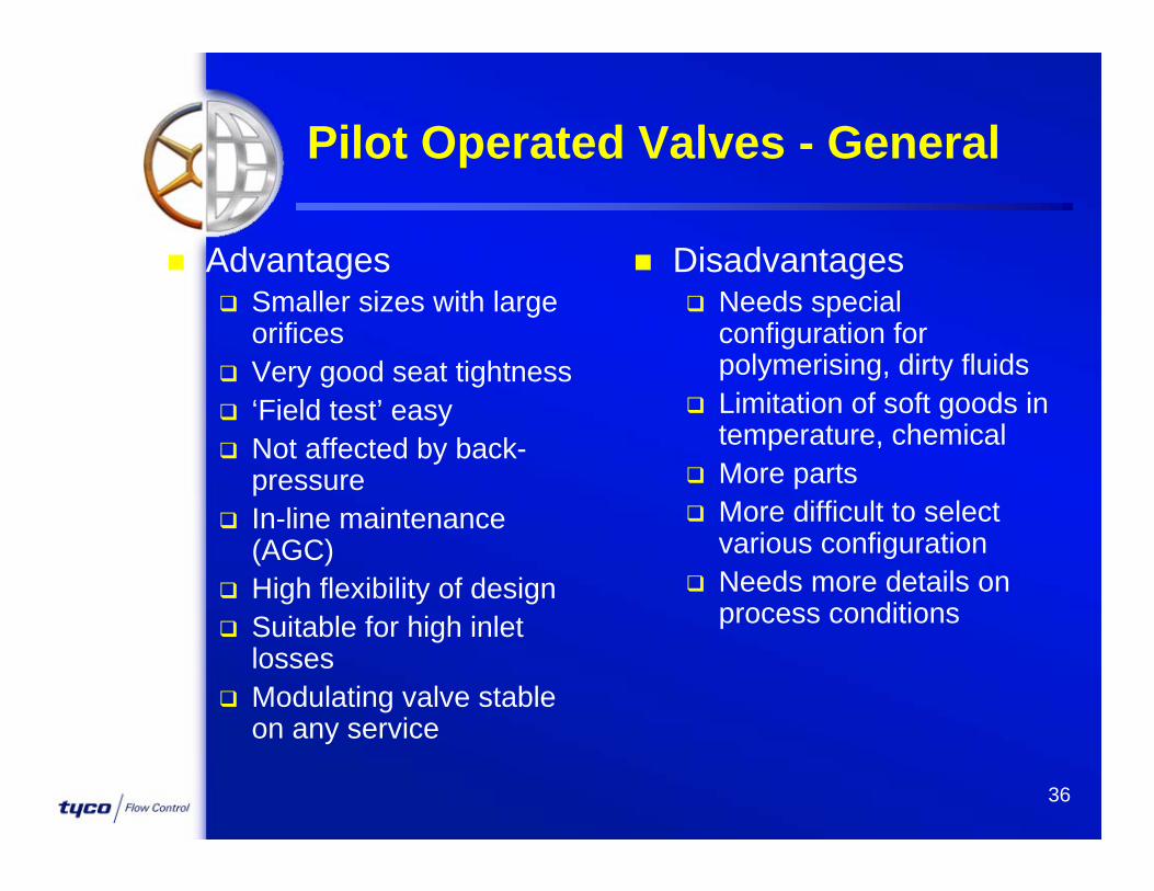
Pilot Operated Valves - General
Advantages Smaller sizes with large
orifices Very good seat tightness ‘Field test’ easy Not affected by back-
pressure In-line maintenance
(AGC) High flexibility of design Suitable for high inlet
losses Modulating valve stable
on any service
Disadvantages Needs special
configuration for polymerising, dirty fluids
Limitation of soft goods in temperature, chemical
More parts More difficult to select
various configuration Needs more details on
process conditions
36
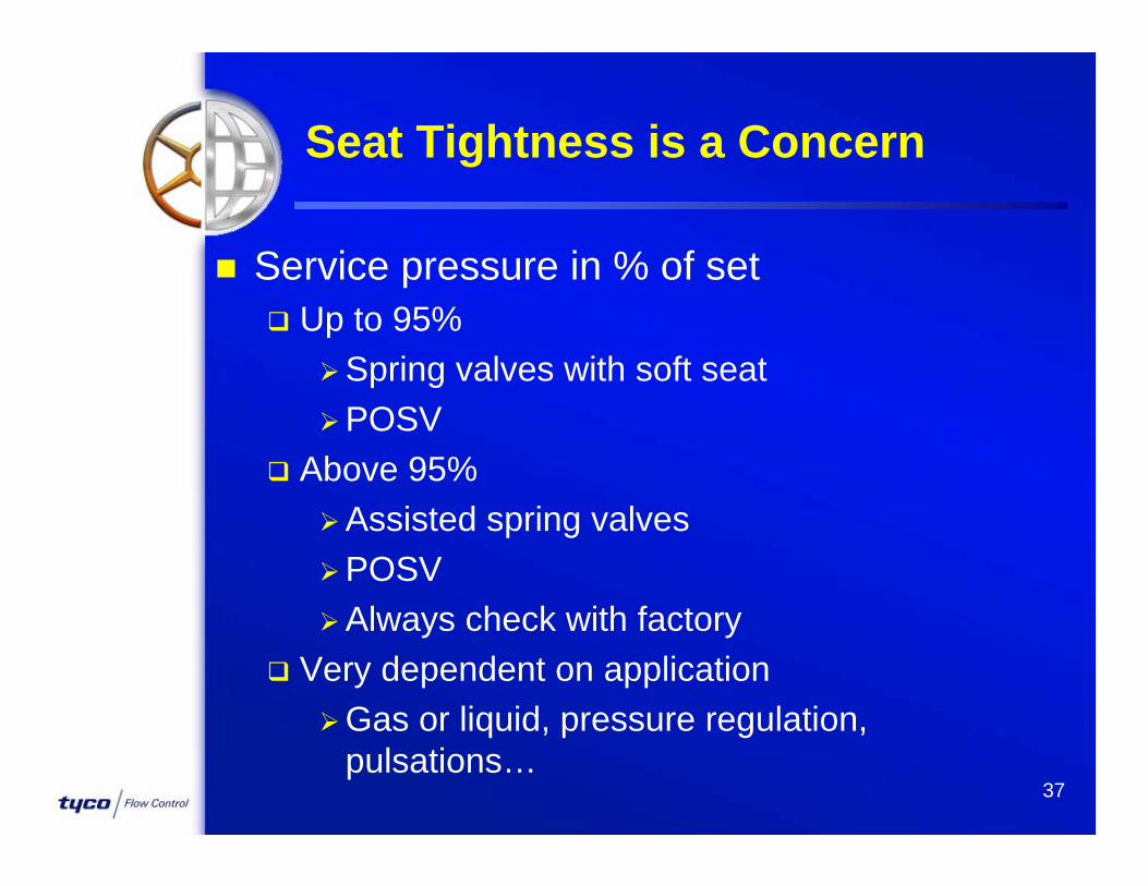
Seat Tightness is a Concern
Service pressure in % of set Up to 95%
Spring valves with soft seatPOSV
Above 95%Assisted spring valvesPOSVAlways check with factory
Very dependent on applicationGas or liquid, pressure regulation,
pulsations…37
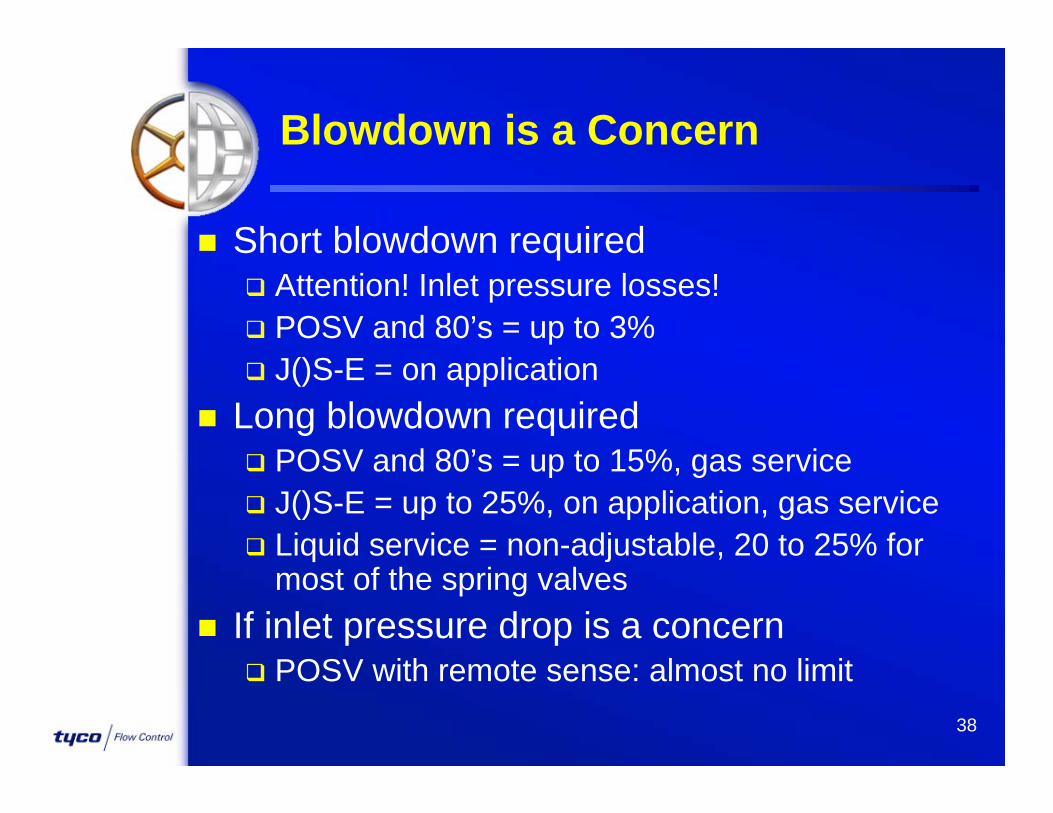
Blowdown is a Concern
Short blowdown required Attention! Inlet pressure losses! POSV and 80’s = up to 3% J()S-E = on application
Long blowdown required POSV and 80’s = up to 15%, gas service J()S-E = up to 25%, on application, gas service Liquid service = non-adjustable, 20 to 25% for
most of the spring valves If inlet pressure drop is a concern
POSV with remote sense: almost no limit38
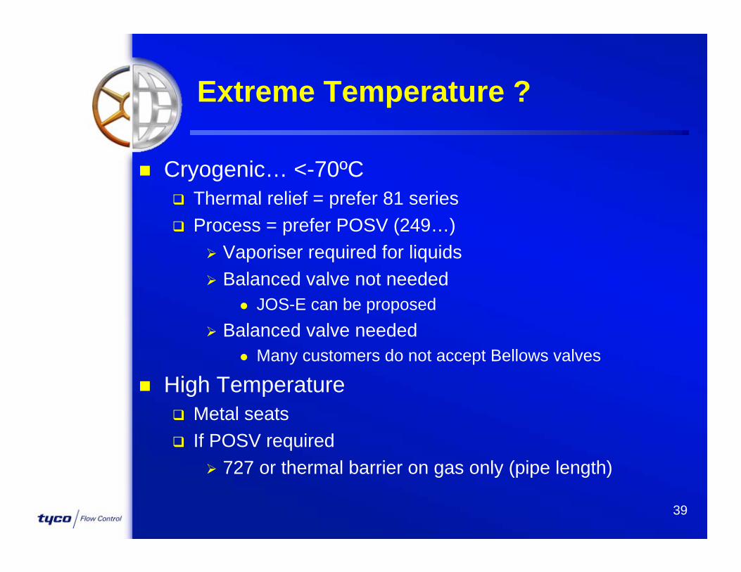
Extreme Temperature ?
Cryogenic… <-70ºC Thermal relief = prefer 81 series Process = prefer POSV (249…)
Vaporiser required for liquids Balanced valve not needed
JOS-E can be proposed Balanced valve needed
Many customers do not accept Bellows valves
High Temperature Metal seats If POSV required
727 or thermal barrier on gas only (pipe length)
39

Weight or Space is Important ?
POSV Particularly in big sizes, up to 50%+ savings
J()S-E A, B, G or H caps (no extended spindle)
Omnis and 80’s available up to G and J orifice Smaller than J()S-E No API 526
40
Large Capacity Required
Spring Loaded valves JOS-E has a T2 orifice (180.1 cm2 with K=0.975) ‘Over – T’ spring valves
Sapag brand with CE mark Or BlockBody®
POSV Full Bore valve, up to 8”x10” (251.3 cm2, gas & liquids) or
10”x14” (464.5 cm2, gas only) straight from catalogue
Multiple valves required PSV 3045-A/B/C/D …
POSV (full bore or even API sizes) or BlockBody®
41
Two-Phase Flow
Modulating POSV recommendedStable alwaysNo risk of over-sizingBack-pressure friendly
Spring loaded valves Recommend
Liquid trimBalanced valvesGas and Liquid certified (same model nr) !
JLT-JBS, 81P, Omni-BP
42
Reciprocating Compressor/Pump
Safety valve may Leak Flutter Open without reason Wear out very quickly
POSV with Pressure Spike Snubber (gas) Liquid Pulsation Dampener (liquid)
43
Set Pressure above API 526
Spring valve required: BlockBody®Using forged blocks, almost no limits
Pilot Operated Safety ValvesMost of the valves can go one rating higher
than shown in catalogue, or more Careful!
Reaction Force Full bore POSV can be supplied with dual outlets
Noise…
44

Now some real Fun!Now some real Fun!
45

SizingSizing
This is funny!This is funny!
46

PRV Sizing Theory
Sizing PRV = Determine the correct orifice for the specific valve type to be used to support a required relieving capacity.
Typical Method: 1 – Establish a set pressure by customer
2 – Determine the relieving capacity by customer
3 – Select an orifice that will flow the required relieving capacity Our Duty !
47

PRV Sizing Theory
How ! Method 1 – By using capacity chart Self explanatory… But only gives capacity for
Air, Water or Saturated Steam.
48
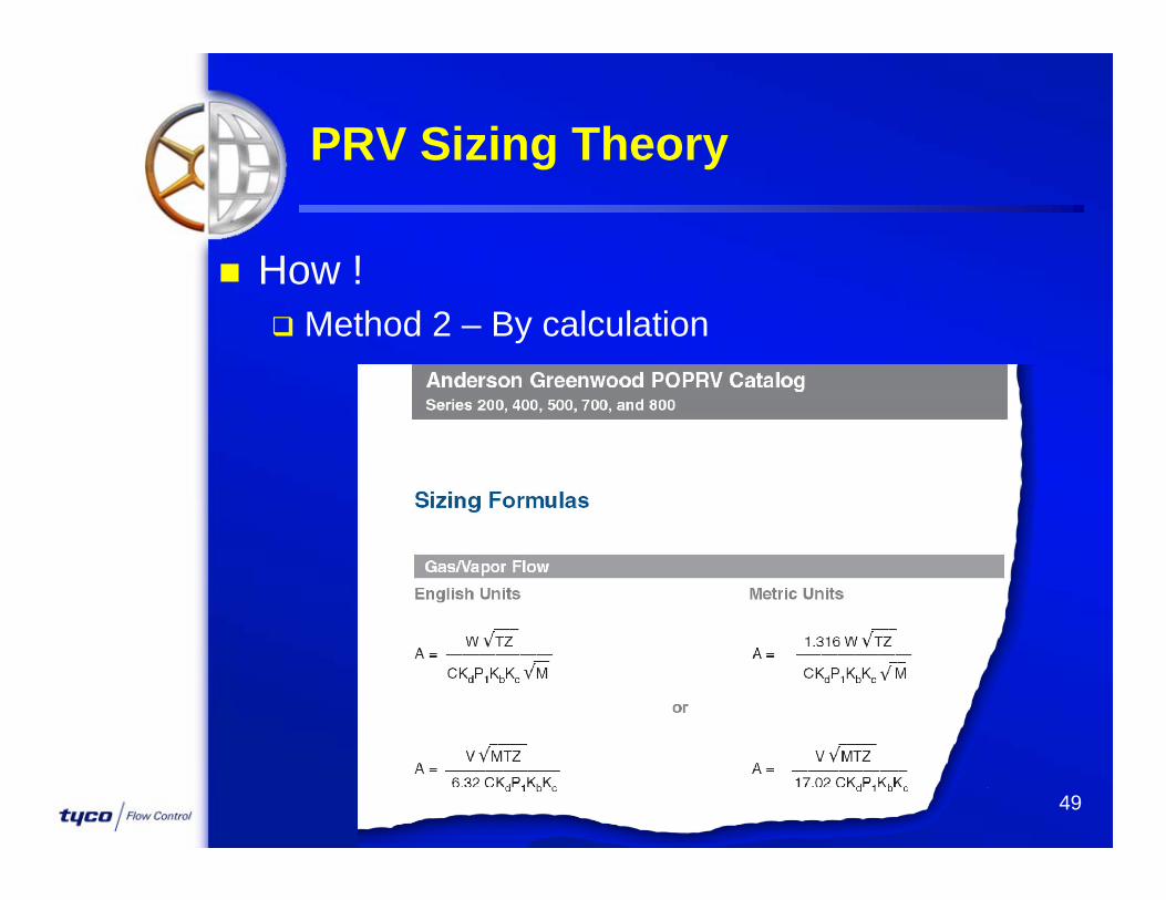
PRV Sizing Theory
How ! Method 2 – By calculation
49

Sizing for Vapors & Gases
Calculated by Capacity Weight or Volume Formulas based on the perfect gas laws
Assume gas does not gain or loss heat (adiabatic)
Energy of expansion converted into kinetic energy
As few gases behave this way correction factors are used (Gas Constants & Compressibility factors)
2 Flowing Conditions: SONIC or SUBSONIC50

Gas Flow above 1.03 Bar G
A nozzle area, cm2 P1 absolute inlet press. barAW flow, kg/hr P2 absolute outlet press. barAV flow, Nm3/hr Kb back-pressure factorC gas constant T relief temp, ºK (ºC+273)K ASME flow coefficient Z compressibility factor
M molecular weightP1 = Set + OverPressure - Inlet Losses + Atmosp.Pres (1.013 bar a)P2 = Back Pressure + Atmospheric Pressure
A T ZM
1316. WC K P K
A V M T Z17.02 C K P K1 b 1 b
51

Gas Flow above 1.03 Bar G
Essential data from customer: W or V, and description of the fluid Set Pressure and Over Pressure Back-pressure Temperature M or Density
Better to have also C or k=Cp/Cv, and Z if unknown: C = 315 and Z=1
A T ZM
1316. WC K P K
A V M T Z17.02 C K P K1 b 1 b
52
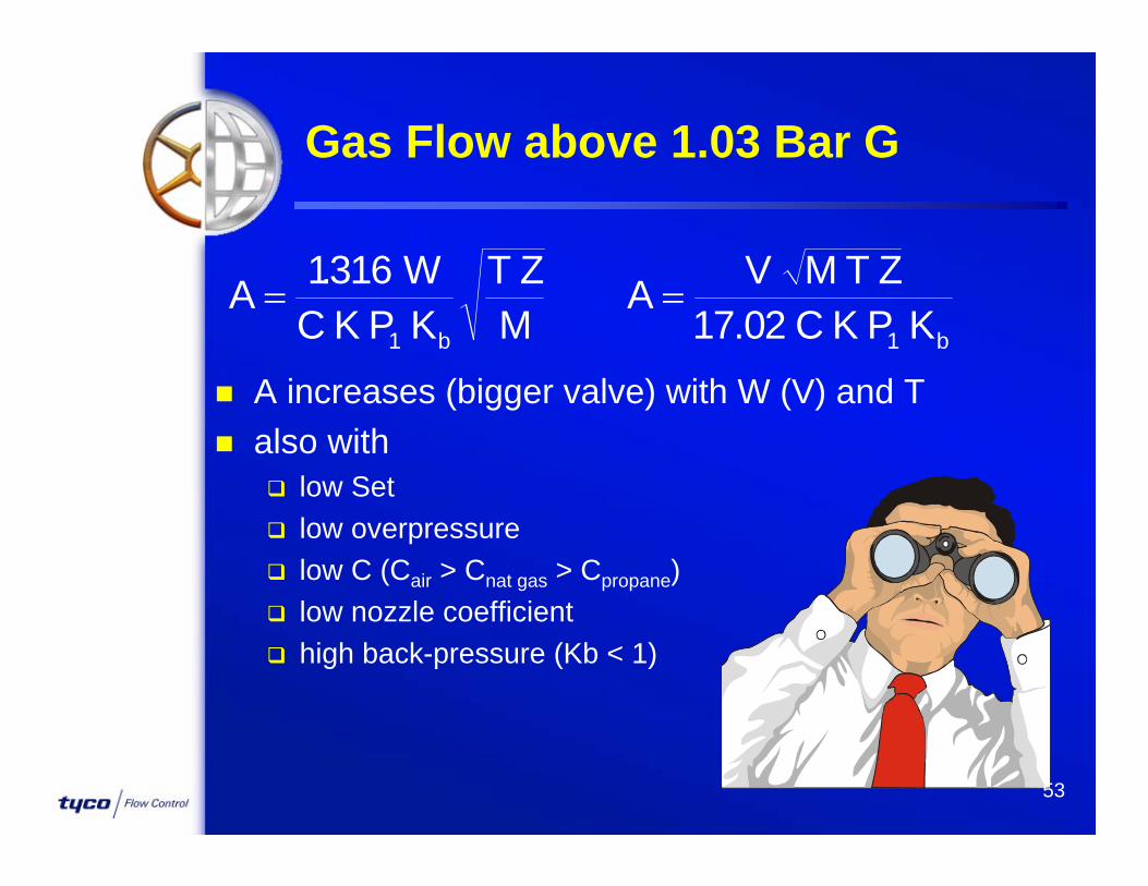
Gas Flow above 1.03 Bar G
A increases (bigger valve) with W (V) and T also with
low Set low overpressure low C (Cair > Cnat gas > Cpropane) low nozzle coefficient high back-pressure (Kb < 1)
A T ZM
1316. WC K P K
A V M T Z17.02 C K P K1 b 1 b
53

Sonic & Subsonic Flow
Theoretical nozzle When BP (P2)< PC, flow is
Sonic capacity depends only on P1 flow reaches the speed of
sound for particular gas no reduction of P2 will
increase the flow
When BP > PC, flow becomes Subsonic flow velocity is now less than
speed of sound then capacity depends on P any increase of P2 will reduce
the velocity thus the actual capacity
Back Pressure
100%
50%
0% 100%50%
Capacity
P PkC
kk
1
121
54
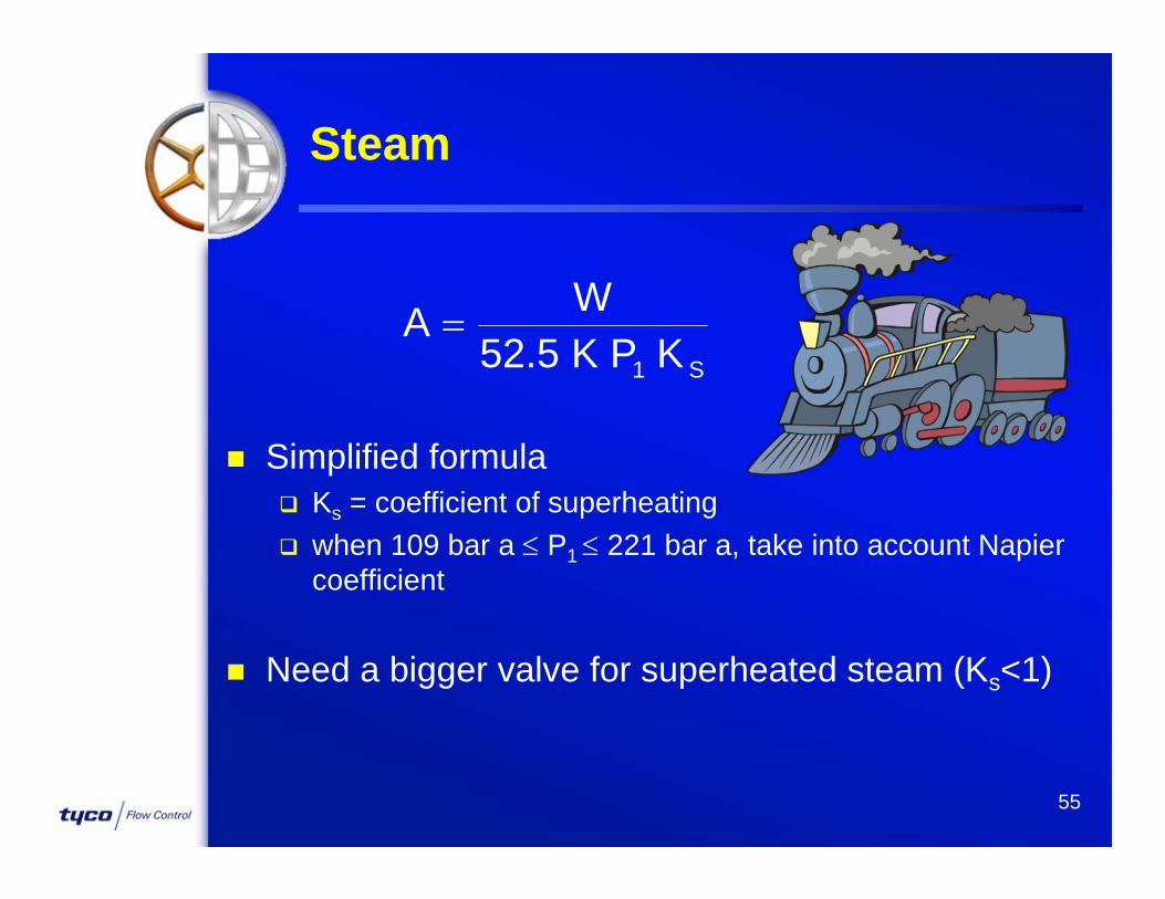
Steam
Simplified formula Ks = coefficient of superheating when 109 bar a P1 221 bar a, take into account Napier
coefficient
Need a bigger valve for superheated steam (Ks<1)
A W
52.5 K P K1 S
55

Steam
Essential data from customer: W Set Pressure and Over Pressure (Code!)
ASME I sizing: 52.5 becomes 52.45! Temperature (will give the superheat factor)
And also any details about the installation, the purity of the steam...
A W
52.5 K P K1 S
56
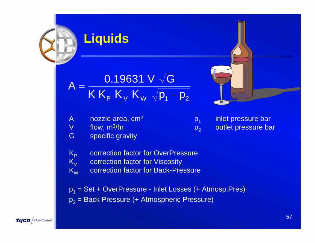
Liquids
A nozzle area, cm2 p1 inlet pressure barV flow, m3/hr p2 outlet pressure barG specific gravity
KP correction factor for OverPressureKV correction factor for ViscosityKW correction factor for Back-Pressure
p1 = Set + OverPressure - Inlet Losses (+ Atmosp.Pres)p2 = Back Pressure (+ Atmospheric Pressure)
Ap
0.19631 V GK K K K pP V W 1 2
57
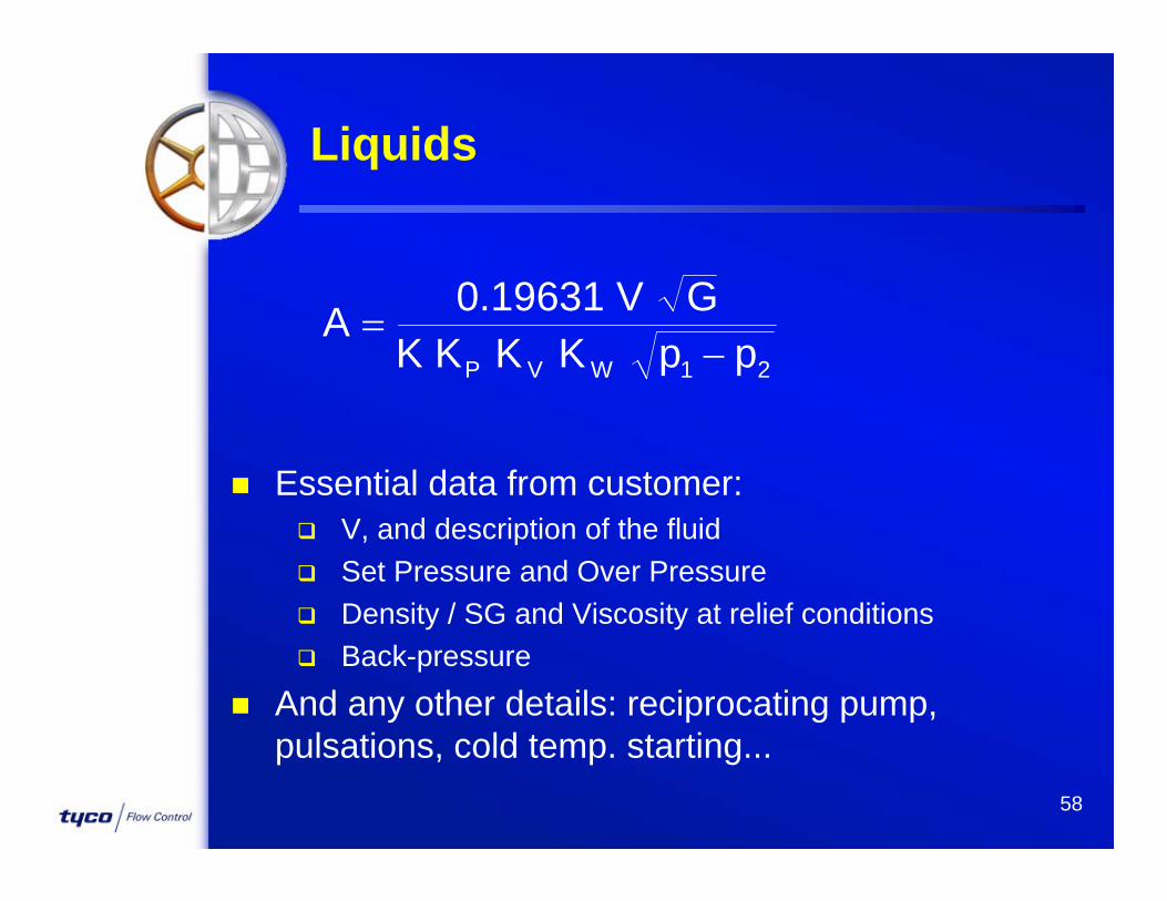
Liquids
Essential data from customer: V, and description of the fluid Set Pressure and Over Pressure Density / SG and Viscosity at relief conditions Back-pressure
And any other details: reciprocating pump, pulsations, cold temp. starting...
Ap
0.19631 V GK K K K pP V W 1 2
58
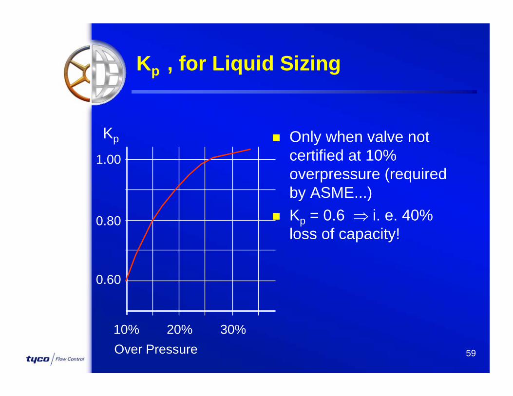
Kp , for Liquid Sizing
Only when valve not certified at 10% overpressure (required by ASME...)
Kp = 0.6 i. e. 40% loss of capacity!
Over Pressure
Kp
10% 30%20%
1.00
0.80
0.60
59
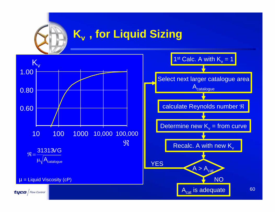
Kv , for Liquid Sizing
100,000
1.00
0.80
0.60
10 1000100 10,000
Kv
catalogueAG V 31313
1st Calc. A with Kv = 1
Select next larger catalogue areaAcatalogue
Determine new Kv = from curve
Recalc. A with new Kv
calculate Reynolds number
A > Acat.YES
Acat is adequate
NOµ = Liquid Viscosity (cP)
60

Conventional Valves on Gas : Constant back pressure
Obtain Kb from manufacturer’s curveBench set = Set - BP
Variable back pressure superimposed: not recommendedbuilt-up <10% okay>10% : definitively NOT!
Kb, Kw... Back Pressure Factors
61

Conventional Valves on Liquid : Constant back pressure
no coefficientBench set = Set - BP
Variable back pressure superimposed: not recommendedbuilt-up <10% okay>10% : definitively NOT!
Kb, Kw... Back Pressure Factors
62

Balanced Valves on Gas : Constant or Variable back pressure
<50% : obtain Kb from manufacturer’s curve>50% : avoid (?!?!)
Balanced Valves on Liquid : Constant or Variable back pressure
(superimposed or built-up)<50% : obtained KW from manufacturer’s
curve>50% : avoid (?!?!)
Kb, Kw... Back Pressure Factors
63
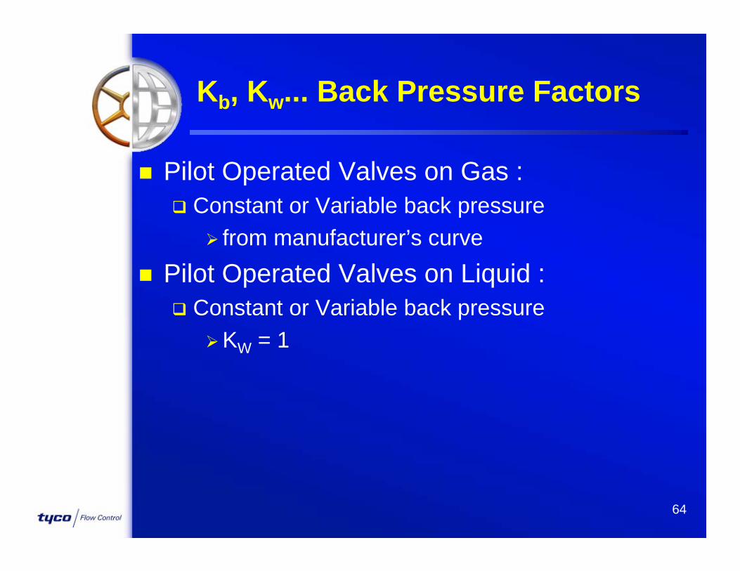
Pilot Operated Valves on Gas : Constant or Variable back pressure
from manufacturer’s curve Pilot Operated Valves on Liquid :
Constant or Variable back pressureKW = 1
Kb, Kw... Back Pressure Factors
64

Example
Type JOS-E, K=0.975 = 18.50 cm2 4M6 (23.23) 81 series, K=0.816 = 22.10 cm2 No
Application on Hydrocarbon Vapors Req’d capacity = 75 000 kg/hr Set = 45 barg, OP =10%, No BP Relief temperature = 100ºC M = 34.0 k=1.31 or C=348 Z=0.94
65

Pressure / Temperature
45 barg
100°C
200°C
66

And When…
And when Set < 1.03 Bar G?
And when Fluid is a Mixture of Gas & Liquid?
We’ll see that
later...
67

68
LNG Characteristics
Natural Gas itself is dangerous: highly flammable suffocating “Green House” effect
Liquid is cryogenic (-162ºC) high level of energy variable composition

NON-FLOWING POP ACTION POPRV (Closed)NON-FLOWING POP ACTION POPRV (Closed)
100%100%
SetSet
100%100%
SetSet
BlowdownBlowdownSeatSeat
ReliefReliefSeatSeat
69

NON-FLOWING POP ACTION POPRV (Relieving)NON-FLOWING POP ACTION POPRV (Relieving)
100%100%
SetSet
100%100%
SetSet0%0%
ReliefReliefSeatSeat
BlowdownBlowdownSeatSeat
70

NON-FLOWING POP ACTION POPRV (Re-Closed)NON-FLOWING POP ACTION POPRV (Re-Closed)
100%100%
SetSet
100%100%
SetSet
BlowdownBlowdownSeatSeat
ReliefReliefSeatSeat
71

We are Great and we should sell it
Widest SV range available We should have the ‘right’ valve for the
application Valuable competitive advantage
We do not just sell what the client wantsWe can propose, use our experienceWhat is most economical in the
short/medium/long term for the client (depends what he cares about)
Look for ‘proposition’ that others cannot match Lowest bid is not always the winner
Still best technical reputation, use it !72