PROVIT Industrial PCs
100
1 PROVIT 4000 USER'S MANUAL Version: 2.0 (December 1995) Model No.: MAPRV4000-E ARCNET is a registered trademark of the Datapoint Corp. ETHERNET is a registered trademark of the XEROX Corp. IBM is a registered trademark of the International Business Machines Corp. MS-DOS is a registered trademark of the Microsoft Corp. Windows is a registered trademark of the Microsoft Corp. OS-2 is a registered trademark of the International Business Machines Corp. PROFIBUS is a registered trademark of the PROFIBUS User Organisation
Transcript of PROVIT Industrial PCs

1
PROVIT 4000USER'S MANUAL
Version: 2.0 (December 1995)Model No.: MAPRV4000-E
ARCNET is a registered trademark of the Datapoint Corp.ETHERNET is a registered trademark of the XEROX Corp.
IBM is a registered trademark of the International Business Machines Corp.MS-DOS is a registered trademark of the Microsoft Corp.Windows is a registered trademark of the Microsoft Corp.
OS-2 is a registered trademark of the International Business Machines Corp.PROFIBUS is a registered trademark of the PROFIBUS User Organisation

2
We reserve the right to change the contents of this manual without warning. The information contained hereinis believed to be accurate as of the date of publication, however, Bernecker and Rainer Industrie-ElektronikGes.m.b.H. makes no warranty, expressed or implied, with regards to the products or the documentationcontained within this book. Bernecker and Rainer Industrie-Elektronik Ges.m.b.H. shall not be liable in the eventof incidental or consequential damages in connection with or arising from the furnishing, performance or useof these products.

3
TABLE OF CONTENTS

4

5
TABLE OF CONTENTS
1. General Information ................................................................................................................................... 91.1 General Information ......................................................................................................................... 111.2 PROVIT 4000 Industrial PC ............................................................................................................ 121.3 Operating System ............................................................................................................................ 141.4 Documentation ................................................................................................................................ 141.5 Model Numbers ............................................................................................................................... 15
2. Start-up .................................................................................................................................................... 172.1 Unpacking ....................................................................................................................................... 192.2 Checking the Delivery ..................................................................................................................... 192.3 Before Power-on ............................................................................................................................. 20
2.3.1 Voltage Selector Switch ......................................................................................................... 202.3.2 Power Cable .......................................................................................................................... 202.3.3 Fan ......................................................................................................................................... 202.3.4 Terminal Block ....................................................................................................................... 20
2.4 PROVIT 4000 Configuration ............................................................................................................ 212.4.1 Operation with One Hard Disk ............................................................................................... 212.4.2 Operation with Two Hard Disks ............................................................................................. 222.4.3 Pentium Setup ....................................................................................................................... 23
2.5 Hard Disk Duplication (MS-DOS) .................................................................................................... 24
3. Installation ................................................................................................................................................ 253.1 19" Rack Installation ........................................................................................................................ 273.2 Door Mount Installation .................................................................................................................... 283.3 Screw Covers .................................................................................................................................. 293.4 Air Circulation .................................................................................................................................. 29
4. Device Description ................................................................................................................................... 314.1 Measurements ................................................................................................................................. 334.2 Display Unit ..................................................................................................................................... 34
4.2.1 Display ................................................................................................................................... 344.2.2 Keyboard ................................................................................................................................ 354.2.3 Key Labelling ......................................................................................................................... 374.2.4 Key Illumination ...................................................................................................................... 374.2.5 Status LEDs ........................................................................................................................... 374.2.6 Disk Drive Cover .................................................................................................................... 384.2.7 Reset Button .......................................................................................................................... 384.2.8 Mounting Holes for 19" Rack ................................................................................................. 384.2.9 Replacing the Display Unit ..................................................................................................... 394.2.10 Touch Screen Information .................................................................................................... 40

6
4.3 Controller ......................................................................................................................................... 414.3.1 Technical Data ....................................................................................................................... 414.3.2 Motherboard ........................................................................................................................... 424.3.3 ISA Bus .................................................................................................................................. 424.3.4 Power Supply ......................................................................................................................... 434.3.5 Disk Drive ............................................................................................................................... 444.3.6 Fan ......................................................................................................................................... 444.3.7 Ground Connection ................................................................................................................ 454.3.8 VGA Controller ....................................................................................................................... 454.3.9 CAN Bus ................................................................................................................................ 464.3.10 Serial Interface ..................................................................................................................... 474.3.11 Parallel Interface LPT1 ........................................................................................................ 484.3.12 Relay Output ........................................................................................................................ 484.3.13 Keypad Connection .............................................................................................................. 494.3.14 Enhanced AT Keyboard Connection ................................................................................... 504.3.15 Coupling to the Keyboard Processor ................................................................................... 504.3.16 Connection Controller - Display ........................................................................................... 504.3.17 Watchdog ............................................................................................................................. 504.3.18 Temperature Monitoring ....................................................................................................... 504.3.19 Jumper ................................................................................................................................. 514.3.20 INTERACT Hardware Key ................................................................................................... 554.3.21 Operation of the Controllers without the Display Unit .......................................................... 57
4.4 Hard Disk ......................................................................................................................................... 594.5 Power Cable .................................................................................................................................... 61
5. Software ................................................................................................................................................... 635.1 B&R I/O Area ................................................................................................................................... 655.2 Key Illumination ............................................................................................................................... 66
5.2.1 Function Key LEDs ................................................................................................................ 665.2.2 Softkey Key LEDs .................................................................................................................. 66
5.3 User LED ......................................................................................................................................... 675.4 Relay Output ................................................................................................................................... 675.5 Temperature Monitoring .................................................................................................................. 67
6. Memory Assignments .............................................................................................................................. 696.1 Memory Assignments ...................................................................................................................... 71
6.1.1 RAM - Address Assignments ................................................................................................. 716.1.2 I/O Address Assignments ...................................................................................................... 716.1.3 Interrupts ................................................................................................................................ 72

7
7. Keypad Modules ...................................................................................................................................... 737.1 Overview ......................................................................................................................................... 757.2 General Information ......................................................................................................................... 76
7.2.1 Measurements ....................................................................................................................... 767.2.2 Standard or Special Keypad Modules .................................................................................... 76
7.3 Standard Keypad Modules .............................................................................................................. 777.3.1 Connection to the PROVIT 4000 or Other Keypad Modules ................................................. 777.3.2 Relationship Between Keypad Module and Display Unit ....................................................... 787.3.3 Keypad Module Cable - 90 cm............................................................................................... 797.3.4 Keypad Module 16 Keys ........................................................................................................ 807.3.5 Keypad Module 12+4 Keys .................................................................................................... 817.3.6 Keypad Module 8 Keys .......................................................................................................... 827.3.7 Keypad Module 4 Keys .......................................................................................................... 83
7.4 Special Keypad Modules ................................................................................................................. 847.4.1 Dummy Module ...................................................................................................................... 847.4.2 E-Stop Button ......................................................................................................................... 857.4.3 Key Switch ............................................................................................................................. 867.4.4 Start/Stop ............................................................................................................................... 87
7.5 Accessories ..................................................................................................................................... 88
8. Options and Accessories ......................................................................................................................... 898.1 Memory Expansion .......................................................................................................................... 918.2 CENTRONICS/Online Converter .................................................................................................... 948.3 PROFIBUS Network Card ............................................................................................................... 948.4 ARCNET Network Card .................................................................................................................. 948.5 ETHERNET Network Card .............................................................................................................. 948.6 Accessories ..................................................................................................................................... 94
Index ............................................................................................................................................................ 95

8

9
SECTION 1GENERAL INFORMATION

1 0
1 1
1.1 GENERAL INFORMATION
PROVIT 4000 is an Industrial PC that distinguishes itself with its high capacity to serve in an industrialenvironment, functionality and flexibility.
Capacity to Serve in an Industrial Environment
- TFT/LCD Displays- Scratch resistant, anti-reflection safety glass- Front is dust and water resistant in compliance with the IP54 (NEMA 12) standard- Large temperature range, software controlled temperature monitoring- Four serial interfaces (three are electrically isolated)- Device complies with DIN-IEC 68-2-27 shock tests and DIN-IEC 68-2-6 vibration tests
Functionality
- Four different display units- Several standard motherboards with different processor performance- Up to 8 MBytes working memory (expandable)- 3.5" disk drive, 1.44 MByte- Parallel interface LPT1- Two RS232 interfaces- One RS232/TTY interfaces- One RS232/RS485 interfaces- CAN interfaces- Interface for external keyboard- Connection of keypad modules possible- One relay output- Matrix keyboard and softkey function keys with key LEDs- Function keys can be labelled with insertable strips
Flexibility
- Several operating systems (MS-DOS, OS-2, ...)- Simple installation in 19" frame rack or door mount- Two plug in hard disks- Four slots for application specific cards- Optional ARCNET, ETHERNET or PROFIBUS network card

1 2
1.2 PROVIT 4000 INDUSTRIAL PC
The following table contains an overview of the components, accessories, equipment and connectionpossibilities of the PROVIT 4000 Industrial PC.
PROVIT 4000
Controller
Display Units
Color Monochrome
5D4000.01 5D4000.04TFT color LCD monochrome
Touch Screen VGA (640 * 480 pixels)VGA (640 * 480 pixels)
5D4000.03LCD STN color
VGA (640 * 480 pixels)
5D4000.05TFT color
VGA (640 * 480 pixels)
Hard Disk
• Up to two hard disks can be inserted
• Plug-in hard disks
• Can be delivered with a memory capacity of ≥ 120 MBytes or ≥ 340 MBytes
Processor: 486SLC2-25/50486SLC2-33/66486DX4-100Pentium-100
Power Cable
• Power cable with connector that can be screwed onto PROVIT 4000
• Can be delivered with grounded plug or open cable end(for international connections)

1 3
Accessories
• Replacement filter
• Cover plate for use without display unit
• Legend sheet templates
• Accessory pack (screws, washers, ...)
• IBM AT enhanced keyboard (19")
• PS2 keyboard adapter
• Memory expansions
• PROFIBUS card
• Serial interface card
• Printer cable (CENTRONICS) 1.8 m
• MS-DOS operating system
• Phoenix PC Card Manager Plus
• MKEY Utility for PROVIT 2000/4000
Connection Possibilities / Equipment(partially dependent on controller)
• Disk drive (3.5" / 1.44 MByte)
• Printer
• AT enhanced keyboard
• B&R keypad modules
• External monitor
• Up to 8 MBytes RAM
• Math co-processor
• Interfaces
• Networks
• Field bus
1 4
1.3 OPERATING SYSTEM
Several operating systems can be used because of the 100 percent compatibility to the IBM AT Standard. TheMS-DOS operating system can be obtained from B&R on request in German or English.
When ordering the PROVIT 4000 Industrial PC as a set, you can specify if MS-DOS should be pre-installed:
Model Number for Pre-installaion: 5A4000.00
1.4 DOCUMENTATION
The following documentation is included with the delivery of the PROVIT 4000:
- PROVIT 4000 User's Manual- MKEY Utilities User's Manual- Motherboard User's Manual
If ordered:
- MS-DOS User's Manual
When required, additional supplement or correction sheets from B&R will be enclosed.

1 5
1.5 MODEL NUMBERS
Controller
Controller C4000.01 - 486SLC2-25/50, 4 MB DRAM 5C4000.01
Controller C4000.02 - 486SLC2-33/66, 4 MB DRAM 5C4000.02
Controller C4000.03 - 486DX4-100, 8 MB DRAM 5C4000.03
Controller C4000.04 - Pentium-100, 8 MB DRAM 5C4000.04
Product Model No.
Display Units
Display TFT Color, Touch - 640 * 480, Diagonal: 9.4" 5D4000.01
Display LCD Color - 640 * 480, Diagonal: 9.4" 5D4000.03
Display LCD B/W - 640 * 480, Diagonal: 9.4" 5D4000.04
Display TFT Color - 640 * 480, Diagonal: 9.4" 5D4000.05
Keypad Modules
Keypad Module - 16 Keys 4E0011.01-090
Keypad Module - 12 + 4 Keys 4E0021.01-090
Keypad Module - 8 Keys 4E0031.01-090
Keypad Module - 4 Keys 4E0041.01-090
Keypad Module - Dummy Module 4E0050.01-090
Keypad Module - E-Stop Switch 4E0060.01-090
Keypad Module - Key Switch 4E0070.01-090
Keypad Module - Start/Stop 4E0080.01-090
Accessories
Hard Disk ≥ 120 MB 5A4000.01
Hard Disk ≥ 340 MB 5A4000.03
Power Cable with Plug - PROVIT 3030/4000 9A0001.01
Power Cable without Plug - PROVIT 3030/4000 9A0001.02
Replacement Filters for Fan (10 pack) 5A4001.01
Cover Plate - PROVIT 4000 5A4002.01
Accessory Pack - PROVIT 4000 5A4003.01
Legend Sheet Templates - PROVIT 4000 5A4003.02

1 6
Special Accessories
IBM AT Keyboard 19" - German 9A0002.01-010
IBM AT Keyboard 19" - English 9A0002.01-020
IBM AT Keyboard 19" - German IP65 9A0002.03-010
IBM AT Keyboard 19" - English IP65 9A0002.03-020
PS2 Keyboard Adapter - AT Connector (F) to PS2 Plug 9A0002.02
1 MB Memory Expansion - 1 MB * 9 (30 pin) 9A0004.01
4 MB Memory Expansion - 4 MB * 9 (30 pin) 9A0004.02
4 MB Memory Expansion - 1 MB * 36 (72 pin) 9A0004.03
16 MB Memory Expansion - 4 MB * 36 (72 pin) 9A0004.04
PROFIBUS ISA Card 5A1104.00-090
RS232 ISA Card 5A1102.00-090
CENTRONICS Cable 1.8 m 9A0005.01
MS-DOS German 9S0000.01-010
MS-DOS English 9S0000.01-020
Pre-installation PROVIT 4000 5A4000.00
PROVIT MKEY Dev Kit - Modular Key Blocks 5S0001.02-090
Touch Screen Utilities 5S0003.01-090
PROVIT PC Card Utilities - Phoenix PC Card Manager 5S0002.01-020
Legend Sheet Templates PANELWARE (blue) 4A0005.00-000

1 7
SECTION 2START-UP

1 8

1 9
2.1 UNPACKING
1. Open carton2. Remove the package with documentation and accessories3. Remove the PROVIT 4000 together with the packing material and place on a flat surface4. Carefully remove all packing material
2.2 CHECKING THE DELIVERY
The packing material used for the PROVIT 4000 Industrial PC is an appropriate safeguard against damageduring normal transport. If in spite of these measures damage is noticed, the device should not be put intooperation. In this case, please contact the B&R office from which the device was purchased.
Contents of delivery:
The contents described below are order dependent .
ACCESSORIES
2 Pole Terminal Block4 Screws4 Washers4 Cage Nuts4 Nuts4 Lock Washers
M6M6M6M6M6
4 Screw Covers2 Legend Sheet TemplatesTerminating Resistor for Keypad Modules
DOCUMENTATION AND SOFTWARE
PROVIT 4000 User's ManualMotherboard Users ManualPROVIT MKEY UtilitiesPROVIT Touch Screen Utilities(only for touch screen display units)
If ordered:
MS-DOS
PROVIT 4000 INDUSTRIAL PC(to be ordered seperately)
- Controller- Display Unit- Power Cable- Hard Disk
F1 F2 F3 F4 F5 F6 F7 F8 F9 F10
POWERHDDUSERWDTEMP.
4 0 0 0P R O V I T
0
1
4
7
2
5
8
3
6
9

2 0
2.3 BEFORE POWER-ON
2.3.1 VOLTAGE SELECTOR SWITCH
The voltage selector switch is optional. It can be found on the left side of the device next to thepower plug. The selector switch is labeled "Voltage Selector".
If the voltage selector is not supplied, the device is equipped with a power supply that has avoltage range from 90 - 260 VAC.
The PROVIT 4000 Industrial PC can be operated with a supply voltage of 230 VAC (Europe) or 115 VAC (USA).The voltage selector setting must correspond with the supply voltage to be connected.
Standard setting for the device when delivered is 230 VAC.
2.3.2 POWER CABLE
The power cable is not included with the delivery of the PROVIT 4000 Controller. It must be ordered separately.The cable is approx. 1.8 m long.
Model Number Power Cable
9A0001.01 Cable with power plug
9A0001.02 Cable without power plug
The connection to the device is made with a screw-on plug. The power mains can be connected with a powerplug or directly to the supply lines.
Attention:
- Only power plugs with protective ground may be used.- The installation may only be made by qualified personnel.- Make sure the connection meets the regulations for electrical installations in your area.
2.3.3 FAN
A fan cover and dust filter is included with the delivery of the PROVIT 4000. Mounting procedure for the fancover:
- Insert dust filter in the fan cover- Mount fan cover on fan
The condition of the filter is to be checked regularly. If necessary, the filter must be changed. Spare filters areavailable from B&R in 10 packs (5A4001.01).
2.3.4 TERMINAL BLOCK
The terminal block for the relay output is not installed when the device is delivered. It must be installed by theuser.

2 1
2.4 PROVIT 4000 CONFIGURATION
The configuration of the PROVIT 4000 Industrial PC is carried out with the help of BIOS Setup. Only thestandard keyboard driver is provided in BIOS Setup.
2.4.1 OPERATION WITH ONE HARD DISK
1) Pull the power plug.
2) Insert the hard disk in the master slot (see Section "4.4 Hard Disk"). The drive designation is c:
3) Reinsert power plug.
4) Enter BIOS Setup:Entering BIOS Setup is done during the system RAM check. The BIOS start -up message indicates whichkey has to be pressed (mostly [Del], it is another key for controllers with a Pentium processor).
5) Determine hard disk type.This set is not required for the controller 5C4000.04, since the Pentium processor determines the hard disktype automatically.
For other controllers, the menu item "Auto Detect Hard Disk" or "IDE HDD Auto Detection" (5C4000.03)must be selected and started.The following message "Accept Parameters for C: (Y/N) ? N" is to be answered with [Y].
After BIOS has detected the first hard disk, it searches for a second. This process can be interrupted bypressing the [Esc] key.The following message "Accept Parameters for D: (Y/N) ? N" is to be answered with [Y].
6) Set date and time if necessary.Select the menu item "Standard CMOS Setup". After the [↵] key has been pressed again, the date and timecan be set.Exit this function with the [Esc] key.
7) Insert the first operating system disk.
8) Exit BIOS Setup:Select the menu item "Write to CMOS and Exit". The message "Write to CMOS and Exit (Y/N) ? N" is tobe answered with [Y].
9) The PC reboots.
10) The operating system is automatically installed. Please read the notes that appear on the screen.

2 2
2.4.2 OPERATION WITH TWO HARD DISKS
1) Pull the power plug.
2) Insert hard disk 1 in the master slot (see Section "4.4 Hard Disk"). The drive designation is c:
3) Insert hard disk 2 in the slave slot. The drive designation is d:
4) Reinsert power plug.
5) Enter BIOS Setup:Entering BIOS Setup is done during the system RAM check. The BIOS start -up message indicates whichkey has to be pressed (mostly [Del], it is another key for controllers with a Pentium processor).
6) Determine hard disk type.This set is not required for the controller 5C4000.04, since the Pentium processor determines the hard disktype automatically.
For other controllers, the menu item "Auto Detect Hard Disk" or "IDE HDD Auto Detection" (5C4000.03)must be selected and started.The following messages "Accept Parameters for C: (Y/N) ? N" and "Accept Parameters for D: (Y/N) ? N"are to be answered [Y].
7) Set date and time if necessary.Select the menu item "Standard CMOS Setup". After the [↵] key has been pressed again, the date and timecan be set.Exit this function with the [Esc] key.
8) Insert the first operating system disk.
9) Exit BIOS Setup:Select the menu item "Write to CMOS and Exit". The message "Write to CMOS and Exit (Y/N) ? N" is tobe answered with [Y].
10) The PC reboots.
11) The operating system is automatically installed. Please read the notes that appear on the screen.

2 3
2.4.3 PENTIUM SETUP
The controller 5C4000.04 is equipped with a Pentium processor. The following note must be adhered to:
The internal interfaces are not allowed to be enabled. The interfaces are set to "disable" by B&Ras a default (in BIOS Setup: "Peripheral Configuration").

2 4
2.5 HARD DISK DUPLICATION (MS-DOS)
The PROVIT 4000 Industrial PC offers hard disk duplication as a feature for mass produce machines. Thecontents of a hard disk (source) is copied to a second hard disk (target). All of the files and data on the sourcehard disk that are necessary for the operation of the system as well as the operating system are copied to thedestination hard disk.
The steps described below are for an MS-DOS System .
The system must be configured for two hard disks (see Section "2.4.2 Operation with Two HardDisks").
Drive c: SourceDrive d:Target (must be formatted if necessary)
1) Pull the power plug.
2) Insert hard disk 1 (source) in the master slot (see Section "4.4 Hard Disk"). The drive designation is c:
3) Insert hard disk 2 (target) in the slave slot. The drive designation is d:
4) Reinsert the power plug.
5) c:\>xcopy c: d: /s/v/e
NOTE: System files and hidden files will not be copied.
6) c:\>sys d:
7) Pull the power plug.
8) Remove hard disk c:.
9) Remove hard disk d: and insert in the master slot.
10) Reinsert the power plug.
11) Enter BIOS Setup:Entering BIOS Setup is done during the system RAM check. The BIOS start -up message indicates whichkey has to be pressed (mostly [Del], it is another key for controllers with a Pentium processor).
12) Select the menu item "Standard CMOS Setup". Define drive d: as "not installed".Exit the function with the [Esc] key.
13) Exit BIOS Setup:Select the menu item "Write to CMOS and Exit". The message "Write to CMOS and Exit (Y/N) ? N" is tobe answered with [Y].
14) The PC reboots.

2 5
SECTION 3INSTALLATION

2 6

2 7
3.1 19" RACK INSTALLATION
Needed for installation:
- Four M6 screws- Four M6 washers- Four cage nuts in 19" rack
Installation:
- Insert cage nuts into the 19" rack.- Place PROVIT 4000 housing in rack.- Fasten the unit to the rack with the hardware provided.- Place the screw covers over the screws.
F1 F2 F3 F4 F5 F6 F7 F8 F9 F10
POWERHDDUSERWDTEMP.
4 0 0 0P R O V I T
0
1
4
7
2
5
8
3
6
9
2 8
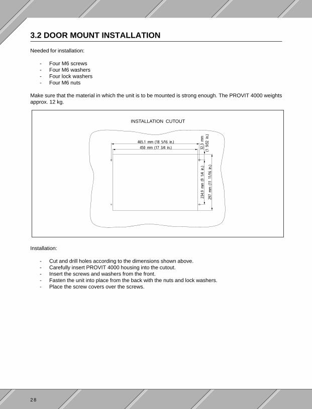
3.2 DOOR MOUNT INSTALLATION
Needed for installation:
- Four M6 screws- Four M6 washers- Four lock washers- Four M6 nuts
Make sure that the material in which the unit is to be mounted is strong enough. The PROVIT 4000 weightsapprox. 12 kg.
Installation:
- Cut and drill holes according to the dimensions shown above.- Carefully insert PROVIT 4000 housing into the cutout.- Insert the screws and washers from the front.- Fasten the unit into place from the back with the nuts and lock washers.- Place the screw covers over the screws.
INSTALLATION CUTOUT
465.1 mm (18 5/16 in.)450 mm (17 3/4 in.)
234.
9m
m(9
1/4
in.)
297
mm
(11
11/1
6in
.)
32.3
mm
(19/
32in
.)

2 9
3.4 AIR CIRCULATION
Proper air circulation is important for the PROVIT 4000. The unit has a fan on the right side of the housing. Thereare air vents on the left and right sides of the housing. The fan and the air vents are not to be blocked!At least a 5 cm (2 ") space must be left between other devices or any other obstructions.
3.3 SCREW COVERS
After installing the device, place the four screw covers over the screws. The cover for the bottom right screwis found under the floppy disk drive cover.
INSTALLING SCREW COVERS REMOVING SCREW COVERS
Set the cover at a slight angle and press with moderatepressure until it clicks into place
Place the end of a small screw driver into the gap betweenthe cover and the housing and pry with moderate pressureuntil the cap pops off

3 0

3 1
SECTION 4DEVICE DESCRIPTION

3 2

3 3
4.1 MEASUREMENTS
NOTE: The cutout measurements for door mount installation are given in section "3.2 Door MountInstallation".
188mm(7 7/16in)
38mm(1 1/2in)
288.
5mm
(11
3/8
in)
10.7
mm
(7/1
6in)
F1 F2 F3 F4 F5 F6 F7 F8 F9 F10
POWERHDDUSERWDTEMP.
4 0 0 0P R O V I T
0
1
4
7
2
5
8
3
6
9
310.
4mm
(12
7/32
in)
465mm(18 5/16in)
59mm(2 5/16in)
33.2mm(1 5/16in)
395.8mm(15 9/16in)10.8mm(7/16in)
483mm(19in)
37.7
mm
(11/
2 in
)23
5mm
(9 1
/4in
)
9mm(11/32 in)

3 4
Model Number 5D4000.01 5D4000.03 5D4000.04 5D4000.05
Display Type TFT color, 256 colors, LCD STN color, 256 colors, LCD monochrome, 16 grey shades, TFT color, 256 colors,CFL back lit CFL back lit CFL back lit CFL back lit
Resolution 640 * 480 pixels 640 * 480 pixels 640 * 480 pixels 640 * 480 pixels
Display Diagonal 9.4" (239 mm) 9.4" (239 mm) 9.4" (239 mm) 9.4" (239 mm)
Touch Screen analog, resistive -- -- --
Ambient Temperature 0 - 50 °C 0 - 40 °C 0 - 50 °C 0 - 50 °C
Relative Humidity 0 - 85 % non-condensing 0 - 85 % non-condensing 0 - 85 % non-condensing 0 - 85 % non-condensing
4.2 DISPLAY UNIT
4.2.1 DISPLAY
There are four different display types:
Jumper:
Jumpers are inserted on the back of the display unit which are display dependent. In order to ensure troublefree operation, these jumpers may not be removed!
Brightness:
The brightness (background lighting) can be adjusted in a range of approx. 20 %. The adjustment is made withthe two shift keys and the cursor key [←] and [→].The shift keys must be pressed at the same time and the brightness is adjusted with the respective cursor key.
Shift Keys:Press both at the same time

3 5
Contrast for the LCD Display:
The contrast on the LCD display can be adjusted. The adjustment is made with the two shift keys and the cursorkeys [↑] and [↓].The shift keys must be pressed at the same time and the contrast is adjusted with the respective cursor key.
4.2.2 KEYBOARD
The built-in matrix keyboard works in parallel to an optional external enhanced AT keyboard or to optionalkeypad modules. The preset key functions of the softkey keys, function key, number keys and cursor keyscorresponds to the ones of an AT keyboard.
The 16 function keys can be labelled with the help of insertable strips (see section "4.2.3 Key Labelling").
The keyboard can be freely configured with the MKEY Utilities. These utilities are on the "PROVIT MKEYUtilities" diskette (model no. 5S0001.01-090). See "PROVIT MKEY Utilities User's Manual".
Four Levels:
Each key can be assigned four functions. The top left function key is used as an example here to show howthe four levels are called.
Shift Keys:Press both at the same time
Level Call Function
1 [F11] F11
2 [⇑up] + [F11] :
3 [⇐left] + [F11] A
4 [⇑up] + [⇐left] + [F11] Ä
A
:
Ä
F11

3 6
Default Key Assignments
The built-in matrix keyboard is already assigned a key code when delivered. There are three different countrycodes in all saved on the unit. You can select between German, English and international according to yourrequirements. This effects characters such as umlauts, special characters etc.The international code is assigned as default. International code means that "Alternate Codes" are sent (e.g."{" refers to the key sequence [Alt] + [0], [1], [2], [3]). This can cause the keys from various operating systems(e.g. MS-Windows®) to be incorrectly interpreted.That means, the German or English key assignments must be selected for a Windows® application.
Selecting the Code Table:
When starting the controller cold, one of the following keys must be pressed:
[F1] ... German Assignments[F2] ... English Assignments[F3] ... International Assignments (default)
The respective key LED is lit briefly if the selection procedure was successful. From this time on, the key codewill be selected automatically each time the unit is booted. The respective LED is lit briefly when booting.

3 7
4.2.3 KEY LABELLING
The 16 function keys are labelled with four legend strips that are inserted under the keypad covering. The stripsare inserted under the disk drive cover.
Two keypad legend sheet templates are delivered with the PROVIT 4000. They can be printed on with a laserprinter and cut using the marks provided. The strips allow for the key LEDs. Legend sheets templates areavailable as replacement accessories (see section "8.6 Accessories").
4.2.4 KEY ILLUMINATION
Softkey keys and function keys are equipped with LEDs that can be controlled with software (see section"5. Software"). A simple operation or status indication is possible by lighting a key LED.
4.2.5 STATUS LEDs
Five status LEDs can be found between the cursor keys.
LED Function
POWER Supply Voltage Indication. Always lit when device is in operation.
HDD Hard Disk LED. Indicates hard disk access.
USER User LED. Can be turned on/off by the user (see section "5. Software").
WD Watchdog LED. Indicates a Watchdog.
TEMP Temperature Monitor. A maximum temperature was exceeded at one of the three temperature measure-ment points.
Key Legend Strips

3 8
4.2.6 DISK DRIVE COVER
The disk drive cover protects the built-in 3.5" disk drive from dust and water (IP54 / NEMA 12).
4.2.7 RESET BUTTON
The reset button is found under the disk drive cover. The button is best actuated with a small screw driver.Pressing the reset button causes a reset with memory test (cold start).
Reset Button
4.2.8 MOUNTING HOLES FOR 19" RACK
Four mounting holes are provided on the display unit for installation in a 19" rack (the fourth is found under thedisk drive cover).
See the following sections:
- "3.1 19" Rack Installation"- "3.3 Screw Covers"
F1 F2 F3 F4 F5 F6 F7 F8 F9 F10
POWERHDDUSERWDTEMP.
4 0 0 0P R O V I T
0
1
4
7
2
5
8
3
6
9
MountingHoles
MountingHoles

3 9
4.2.9 REPLACING THE DISPLAY UNIT
Only replace the display unit with the power cable unplugged!
- Remove the four M5 nuts shown below- Remove the display unit- Insert new display unit- Replace and tighten the four M5 nuts
Remove Nuts Remove Nuts

4 0
4.2.10 TOUCH SCREEN INFORMATION
The display unit is delivered complete with the respective driver for the operation of the Touch Screen.According to the revision of the display unit, either a Dynapro or Elotouch touch screen is used.
If a display unit with an integrated touch screen is used, the COM2 interface is no longer at your disposal!This interface is automatically reserved internally for the operation of the touch screen .
Setting Up the Touch Screen for the Environment:
The installation of both types of touch screens is to be carried out corresponding to the procedure describedin the user's manual. The user's manual is included with the delivery of the display unit. The installation is carriedout automatically with an "install" program.
Make sure to select the proper touch screen:
Type Touch Screen
Dynapro Dynapro-SerialorDynapro-Serial not SC3
Elotouch E271-2210 Accu Touch
The touch screen is to be calibrated after successful installation (hardware calibration). This procedure isdescribed in the user's manual.
The calibration is carried out with the following program:
Type Program
Dynapro TBCAL
Elotouch ELOCALIB
Mouse emulation is to be loaded at the end of the calibration for the operation of the driver.
Example "autoexec.bat" file:
Type "autoexec.bat"
Dynapro TBDRIVER 2 /c:9600,n,8,1
If a mouse is to be used parallel to the touch screen, the mouse driver "mouse" must be called with thefollowing entry.
TBMOUSE 1
Elotouch ELODEV 2210,2,9600 -c.....
The calibration data is entered from ELOCALIB ("-c.....").
MONMOUSE -m5

4 1
Model Number 5C4000.01 5C4000.02 5C4000.03 5C4000.04
Processor 486SLC2-25/50 486SLC2-33/66 486DX4-100 Pentium-100
Internal Cache 16 KBytes 16 KBytes 8 KBytes 16 KBytes
External Cache -- 64 KBytes 256 KBytes 256 KBytes
Working Memory 4 MBytes 4 MBytes 8 MBytes 8 MBytes(DRAM) (max. 16 MBytes) (max. 16 MBytes) (max. 64 MBytes) (max. 128 MBytes)
Math Co-processor -- YES YES YES
Disk Drive 3.5" / 1.44 MByte
Hard Disk Two hard disks can be inserted (different sizes)
Measurements Width * Height * Depth483 * 310 * 188 mm19 * 12 1/4 * 7 3/8 in
7 Module (Height in modules: 1 module = 1 3/4 in)
Front Dust and water resistant (IP54 / NEMA 12)
Installation 19" frame rack or door mount
Total Weight approx. 12 kg
Supply Voltage 90 to 260 VAC 1)
47 to 440 Hz
Power Consumption 170 W max.
Fuse T 3.15 A / 250 V
Interfaces AT compatible keyboard interfaceConnector for up to seven keypad modules
Parallel interfaceRS232 interface electrically isolated
RS232 interface not electrically isolatedRS232/TTY interface electrically isolated
RS232/RS485 interface electrically isolatedCAN interface
Keypad 12 number keys, 4 cursor keys, 10 softkey keys with key LEDs,16 function keys with key LEDs, 2 shift keys
Slots Four standard ISA (16 bit) AT slots
Display Four different display typesResolution 640 * 480 pixels
External Monitor Connector for VGA Monitor
Digital Output A potential free relay contact, 250 VAC or 30 VDC, 1 A
Operating System e.g. MS-DOS, English or German
Options PROFIBUS network card, ARCNET network card, ETHERNET network card
Shock / Vibration Shock tested to DIN-IEC 68-2-27 standard / vibration tested to DIN-IEC 68-2-6 standard
Operating Temperature 0 to 50 °C0 to 40 °C with color LCD
Relative Humiditywith Display Unit 0 to 85 %, non-condensingwithout Display Unit 0 to 95 %, non-condensing
4.3 CONTROLLER
4.3.1 TECHNICAL DATA
1) See section "2.3.1 Voltage Selector Switch".

4 2
4.3.2 MOTHERBOARD
Standard boards with different processors are offered from B&R. The technical data for your processor canbe found in the motherboard description.
Expanding working memory is described in section "8.1 Memory Expansion".
4.3.3 ISA BUS
The PROVIT 4000 Industrial PC provides a 16 bit ISA bus with four slots. Two long and two short cards canbe inserted.
Card Installation / Removal:
In order to get to the bus, the housing cover must be removed. The two screws shown below must be removed.
Remove Screws

4 3
Technical Data: 90 - 260 VAC170 W max.
47 - 440 Hz
Fuse: T 3.15 A / 250 V
Voltage Selector Switch:
The voltage selector switch is optional. It can be found on the left side of the device next to thepower connection. The voltage selector switch is labelled "Voltage Selector".
If the voltage selector switch is not provided, the unit is equipped with a power supply that hasa voltage range of 90 - 260 VAC.
The PROVIT 4000 Industrial PC can be operated with a supply voltage of 230 VAC (Europe) or 115 VAC (USA).The position of the voltage selector switch must be checked before power is connected.
The standard setting for delivery is 230 VAC.
Power Cable:
The power cable is described in section "4.5 Power Cable".
4.3.4 POWER SUPPLY
The power supply is mounted on the controller. Power plug, fuse and voltage selector swtch (optional) can befound on the left side of the device.
230
115Voltage Selector Switch
(optional)
FuseT 3.15 A / 250 V
Power Plug

4 4
4.3.5 DISK DRIVE
The PROVIT 4000 Industrial PC provides a 3.5" disk drive that can be accessed from the front. BothDD diskettes (720 KByte) or HD diskettes (1.44 MByte) can be used. The disk drive is protected against dustand water (IP54 / NEMA 12) with a cover.
If the unit is to be operated in conditions with heavy dust or spray, the cover must be closed. There will be anaudible click when the cover is properly closed.
The LED indicates disk access.
Key Legend Strips
Reset Button
Disk DriveOpening
Diskette Eject ButtonLED Display
4.3.6 FAN
The fan serves to cool the device. It is automatically turned on and off depending on the temperature at the threemeasurement points.The following accessories are delivered with the PROVIT 4000:
Fan cover mounting procedure:
- Insert dust filter in fan cover- Mount fan cover on fan
The filter is to be checked regularly and replaced when required. Replacement filters are available from B&Rin 10 packs (5A4001.01).
aaaaaaaaaaaaaaaaaaaaaaaaaaaaaaaaaaaaaaaa
aaaaaaaaaaaaaaaaaaaaaaaaaaaaaaaaaaaaaaaaaaaaaaaaaaaaaaaaaaaaaaaaaaaaaaaaaaaaaaaaaaaaaaaaaaaaaaaaaaaaaaaaaaaaaaaaaaaaaaaaaaaaaaaaaaaaaaaaaaaaaaaaaaaaaaaaaaaaaaaaaaaaaaaaaaaaaaaaaaaaaaaaaaaaaaaaaaaaaaaaaaaaaaaaaaaaaaaaaaaa
aaaaaaaaaaaaaaaaaaaa
aaaaaaaaaaaaaaaaaaaaaaaaaaaaaaaaaaaaaaaaaaaaaaaaaaaaaaaaaaaaaaaaaaaaaaaaaaaaaaaaaaaaaaaaaaaaaaaaaaaaaaaaaaaaaaaaaaaaaaaaaaaaaaaaaaaaaaaaaaaaaaaaaaaaaaaaaaaaaaaaaaaaaaaaaaaaaaaaaaaaaaaaaaaaaaaaaaaaaaaaaaaaaaaaaaaaaaaaaaaaaaaaaaaaaaaaaaaaaaaa
aaaaaaaaaaaaaaaaaaaaaaaaaaaaaaaaaaaaaaaa
aaaaaaaaaaaaaaaaaaaaaaaaaaaaaaaaaaaaaaaaaaaaaaaaaaaaaaaaaaaaaaaaaaaaaaaaaaaaaaaaaaaaaaaaaaaaaaaaaaaaaaaaaaaaaaaaaaaaaaaaaaaaaaaaaaaaaaaaaaaaaaaaaaaaaaaaaaaaaaaaaaaaaaaaaaaaaaaaaaaa
aaaaaaaaaaaaaaaaaaaaaaaaaaaaaaaaaaaaaaaaaaaaaaaaaaaaaaaaaaaa
Fan Cover Dust Filter

4 5
4.3.7 GROUND CONNECTION
An additional ground connection is to be made to the ground connector on the left side of the PROVIT 4000Industrial PC.
4.3.8 VGA CONTROLLER
Technical Data:
Memory 0.5 MByte RAM
Resolution 640 * 480 pixels
Display Control Various display units can be controlled
External Monitor Can be controlled (resolution: 640 * 480)
Make sure that a multisync monitor with a horizontal frequency of at least 25 kHz is used forparallel operation of monitor/display unit. The vertical frequency is approx. 54Hz for this typeof operation.
If an external monitor is used without a display unit, these limitations are no longer valid (seesection "4.3.21 Operation of the Controller without a Display Unit").
Pin Assignment Pin Assignment
1 red 9 n.c.
2 green 10 GND
3 blue 11 n.c.
4 n.c. 12 n.c.
5 GND 13 HSYNC
6 GND 14 VSYNC
7 GND 15 n.c.
8 GND
515
11 1
10
15 Pin D-TypeConnector (F)
6

4 6
4.3.9 CAN BUS
The CAN bus can be found on the left side of the PROVIT 4000 Industrial PC. An INTEL 82527 processor isused as CAN controller.
The CAN bus is supplied with power either internally or externally. The selection is made with the help of aswitch.The CAN bus is set to the potential of COM1 which is electrically isolated with internal supply.An external supply voltage is used on the bus with external supply.
Pin Assignment
1
2 CAN L
3 GND
4
5
6 GND
7 CAN H
8
9 Vx
5
1
9
6
9 Pin D-TypeConnector (M)
CAN BusVoltage Supply
internal (COM1)
external

4 7
COM1 COM2
RS232 interface RS232 interface
electrically isolated not electrically isolated
up to 115 kBaud up to 115 kBaud
Pin Assignment Pin Assignment
1 DCD 1 DCD
2 RXD 2 RXD
3 TXD 3 TXD
4 DTR 4 DTR
5 GND 5 GND
6 DSR 6 DSR
7 RTS 7 RTS
8 CTS 8 CTS
9 RI 9 RI
COM3 COM4
RS232 / TTY interface RS232 / RS485 interface
electrically isolated electrically isolated
16 Byte UART FIFO (Rev. ≥ 10.xx) 16 Byte UART FIFO
RS232: up to 115 kBaud RS232: up to 115 kBaud
TTY: up to 19200 Baud RS485: up to 115 kBaud
Pin RS232 TTY Pin RS232 RS485
1 TXD 1 RE 1)
2 RXD 2 RXD
3 TXD 3 TXD
4 DTR 4 DTR
5 GND TXD Ret 5 GND GND
6 RXD 6 DATA
7 RTS 7 RTS
8 CTS 8 CTS
9 RXD Ret 9 DATA
4.3.10 SERIAL INTERFACE
The serial interfaces COM1 to COM4 can be found on the left side of the PROVIT 4000 Industrial PC.
1) Pin 1 (RE - receive enable) must beconnected to GND for RS485 operation.
COM2
COM3
COM4COM1
5
1
9
6
9 Pin D-TypeConnector (M)

4 8
4.3.11 PARALLEL INTERFACE LPT1
The parallel interface LPT1 can be found on the left side of the PROVIT 4000 Industrial PC. It is a 25 pin D-typeconnector (F).
Pin Assignment Pin Assignment
1 Data Strobe 14 Autofeed
2 Data 0 15 Error
3 Data 1 16 Printer Init
4 Data 2 17 Printer Select Input
5 Data 3 18 GND
6 Data 4 19 GND
7 Data 5 20 GND
8 Data 6 21 GND
9 Data 7 22 GND
10 Acknowledge 23 GND
11 Busy 24 GND
12 Paper End 25 GND
13 Printer Select Status
4.3.12 RELAY OUTPUT
The relay output can be found on the left side of the PROVIT 4000 Industrial PC. It is a normally open contact.e.g. A horn or lamp can be connected to the relay output.
Pin Assignment
1 Output
2 Ref. Potential
Output Type Relay
Switching Voltage max. 250 VACmax. 30 VDC
Switching Current 1 A
Switching Delaylog. 0 → 1 approx. 6 mseclog. 1 → 0 approx. 3 msec
Wiring
GND
Output
Load
25 Pin D-TypeConnector (F)
1
13
14
25

4 9
Relay Output Protective Circuit:
The relay output generally requires an external protective circuit. It can be placed on the switching load or onthe output. An exact knowledge of the switching load is necessary to size the protective circuit (e.g. internalresistance for contactors and inductivity of the coil). Most manufacturers of contactors and solenoids offerprotective elements for the respective components.
The following elements may be used:
- RC Element: used mostly for AC.
- Varistor: used mostly for AC. Varistors have a relatively short life span, so the use of RC elements ispreferred over the use of varistors.
- Diode: can only be used for DC.
- Diode/Z-Diode Combination: can only be used for DC. This type of protective circuit makes fasterswitching times possible. A higher switching frequency means that the component often becomes verywarm.
4.3.13 KEYPAD CONNECTION
The sockets for the connection of up to seven keypad modules can be found on the left side of the PROVIT 4000Industrial PC. The keypad modules work in parallel to the built-in matrix keypad and to an optional externalenhanced AT keyboard.
1) The keypad modules are only recognized when the device is turned on or after a hardwarereset (pressing the reset button).
2) The operation of the keypad modules is only possible if the display unit is installed.
3) An end plug must be inserted on the last keypad module.
4) The configuration is carried out with the MKEY Utilities.
5) The operation is controlled by the display unit (no additional software required in back-ground - e.g. DOS TSR).

5 0
4.3.14 ENHANCED AT KEYBOARD CONNECTION
The connection of an external enhanced AT keyboard can be made via a 5 pin DIN connector on left side ofthe PROVIT 4000 Industrial PC. The external AT keyboard works in parallel to the built-in matrix keyboard andto optional keypad modules.
The connection can handle a max. 0.5 A.
The keyboard should only plugged in or unplugged with the power disconnected.
4.3.15 COUPLING TO THE KEYBOARD PROCESSOR
The coupling circuit board can be found above the fan. This circuit board establishes the connection from tothe keyboard processor in the display unit.
4.3.16 CONNECTION CONTROLLER - DISPLAY
The connection between the controller and display is made with a plug on the coupling circuit board.
4.3.17 WATCHDOG
The PROVIT 4000 Industrial PC is equipped with a Watchdog. The Watchdog is only activated after theI/O address 312h is accessed.At this point in time, the I/O address must be re-accessed inside a time window of between 25 µsec and70 msec. If the next access does not take place inside of 70 msec, a reset will take place. If access is madetoo fast (access time < 25 µsec), a reset will also take place.
If a Watchdog error occurs, the WD LED is lit. The WD LED remains lit until the device is turned off.
4.3.18 TEMPERATURE MONITORING
Temperature monitoring consists of the evaluation of the three temperature measurement points. The threemeasurement points are:
- CPU (processor)- Display- Power Supply
If one of the three measurement points measures a temperature that is too high, a corresponding bit in theI/O address 302h is set (see section "5.5 Temperature Monitoring"). Additionally, the TEMP LED on the displayunit is lit.
Pin Assignment
1 Keyboard Clock
2 Keyboard Data
3 n.c.
4 GND
5 +5 V

5 1
4.3.19 JUMPER
The jumpers are used for interface, drive and the display settings. There are two different jumper configurationsdependent on the controller revision:
- Controller Rev. < 10.xx- Controller Rev. ≥ 10.xx
Jumper configuration for controllers with a rev. < 10.xx:
Seven rows of jumpers can be found on the top edge of the I/O board. The housing cover has to be removedto access the jumpers. The cover can be removed by loosening the two screws shown below.
Remove Screws
The jumpers are described in the table on the next page. The jumpers are oriented as shown below.
1.11.21.31.41.5
2.12.22.32.4
4.14.24.3
5.15.25.3
3.13.2
6.16.2
7.17.27.37.47.57.6
Video BIOS
Reserve Jumper 7.1 to 7.6

5 2
Jumpers in Row 1
Jumper Function
1.1 disable CAN-IC (Attention: In spite of being disabled, the CAN address area is not freed!)
1.2 CAN IRQ15
1.3 CAN IRQ11
1.4 CAN IRQ10 (default)
1.5 CAN IRQ12
Jumpers in Row 2
Jumper Function
2.1 disable COM1 (address freed)
2.2 disable COM2 (address freed)
2.3 disable HDD (address freed)
2.4 disable FDD (address freed)
Jumpers in Row 3
Jumper Function
3.1 disable LPT1 (address freed)
3.2 disable IRQ7 der LPT1 (Attention: IRQ7 may not be used for plug-in cards!)
Jumpers in Row 4
Jumper Function
4.1 disable COM3 (address not freed)
4.2 COM3 IRQ5
4.3 COM3 IRQ7
Jumpers in Row 5
Jumper Function
5.1 disable COM4 (address not freed)
5.2 COM4 IRQ5
5.3 COM4 IRQ7
Jumpers in Row 6
Jumper Function
6.1 If the device is operated without the front, both jumpers must be inserted.6.2 Attention: In normal operation (operation with front), the jumpers are not to be inserted!

5 3
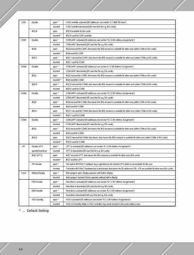
Jumper configuration for controllers with a rev. ≥ 10.xx:
Nine rows of jumpers can be found on the top edge of the I/O board. The housing cover has to be removed toaccess the jumpers. The cover can be removed by loosening the two screws shown below.
Remove Screws
The jumpers are described in the table on the next page. The jumpers are oriented as shown below.
CAN
LPT
FRONT COM1 COM2 COM4 ReserveCOM3Disable
Disable LPT1 FDD Disable
Without Display Disable DisableDisable DisableWithout Display IRQ4* IRQ4IRQ3* IRQ3
IRQ11 IRQ11*IRQ12 IRQ12*IRQ10*
IRQ7* LPT1 HDD DisableITR Disable VGA Standby * ... Default Setting
5 4
CAN Disable open 1) CAN Controller activated (I/O addresses see section "5.1 B&R I/O Area")
inserted CAN Controller deactivated (I/O area free for e.g. ISA cards)
IRQ10 open IRQ10 available for ISA cards
inserted 1) IRQ10 used for CAN Controller
COM1 Disable open 1) COM UART activated (I/O addresses see section "6.1.2 I/O Address Assignments")
inserted COM UART deactivated (I/O area free for e.g. ISA cards)
IRQ4 open IRQ4 not used for COM1, that means this IRQ resource is available for other uses (other COMs or ISA cards)
inserted 1) IRQ4 used for COM1
IRQ11 open 1) IRQ11 not used fro COM1, that means this IRQ resource is available for other uses (other COMs or ISA cards)
inserted IRQ11 used for COM1
COM2 Disable open 1) COM UART activated (I/O addresses see section 6.1.2 I/O Address Assignment")
inserted COM UART deactivated (I/O area free for e.g. ISA cards)
IRQ3 open IRQ3 not used for COM2, that means this IRQ resource is available for other uses (other COMs or ISA cards)
inserted 1) IRQ3 used for COM2
IRQ12 open 1) IRQ12 not used for COM2, that means this IRQ resource is available for other uses (other COMs or ISA cards)
inserted IRQ12 used for COM2
COM3 Disable open 1) COM UART activated (I/O addresses see section "6.1.2 I/O Address Assignments")
inserted COM UART deactivated (I/O area free for e.g. ISA cards)
IRQ4 open 1) IRQ4 not used for COM3, that means this IRQ resource is available for other uses (other COMs or ISA cards)
inserted IRQ4 used for COM3
IRQ11 open IRQ11 not used for COM3, that means this IRQ resource is available for other uses (other COMs or ISA cards)
inserted 1) IRQ11 used fro COM3
COM4 Disable open 1) COM UART activated (I/O addresses see section "6.1.2 I/O Address Assignment")
inserted COM UART deactivated (I/O area free for e.g. ISA cards)
IRQ3 open 1) IRQ3 not used for COM4, that means this IRQ resource is available for other uses (other COMs or ISA cards)
inserted IRQ3 used for COM4
IRQ12 open IRQ12 not used for COM4, that means, that means this IRQ resource is available for other uses (other COMs or ISA cards)
inserted 1) IRQ12 used for COM4
LPT Disable LPT1 open 1) LPT1 is activated (I/O addresses see section "6.1.2 I/O Address Assignment")
(parallel interface) inserted LPT1 is deactivated (I/O area free for e.g. ISA cards)
IRQ7 (LPT1) open IRQ7 not used LPT1, that means this IRQ resource is available for other uses (ISA cards)
inserted 1) IRQ7 used for LPT1
ITR Disable open 1) The built-in INTERACT hardware key is operated via the internal LPT2 which is not available for the user
inserted The built-in INTERACT hardware key is deactivated, that means the I/O addresses 278 - 27F are available for other uses (ISA cards)
Front Without Display open 1) Both jumpers open: Display operates with built-in display
inserted Both jumpers inserted: Device operates without built-in display
FDD Disable open 1) Disk drive is activated (I/O addresses see section "6.1.2 I/O Address Assignments")
inserted Disk drive is deactivated (I/O area free for e.g. ISA cards)
HDD Disable open 1) Hard disk is activated (I/O addresses see section "6.1.2 I/O Address Assignments")
inserted Hard disk is deactivated (I/O area free for e.g. ISA cards)
VGA Standby open 1) VGA is activated (I/O addresses see section "6.1.2 I/O Address Assignments")
inserted VGA is in Standby Mode. A VGA Controller may not be inserted in the same address area
1) ... Default Setting

5 5
4.3.20 INTERACT HARDWARE KEY
The INTERACT hardware key can be used in all PROVIT 4000 Industrial PCs. The controller revision must betaken into consideration:
Controller INTERACT Hardware Key
Rev. < 10.xx For controllers with a rev. < 10.xx, the INTERACT hardware key cannot operate on LPT1 alone. Theoperation of an INTERACT hardware key internally in the device in conjunction with the LPT1parallel interface is not supported. That means, the INTERACT hardware key can only beoperated internally .Furthermore, software package such as e.g. Lap Link which normally use the parallel interface asthe communication port cannot be operated on LPT1!
Rev. ≥ 10.xx For controllers with a rev. ≥ 10.xx, the INTERACT hardware key is operated by the LPT2 interfacewhich is not available for the user. That means, the operation takes place via the I/O addresses 278 -27F. An IRQ is not triggered. The INTERACT hardware key can be operated externally (LPT1) andalso internally (in the key slot). Both can be used together for maintenance work.The limitations stated above concerning the use of software packages are not valid for thesecontrollers!
Key Slot for the INTERACT Hardware Key:
In order to access the key slot for the INTERACT hardware key, the housing cover must be removed. In orderto do this, the two screws shown below must be removed. The circle indicates the area where the key slot canbe found.
Remove Screws
Slot forINTERACTHardware Key
5 6
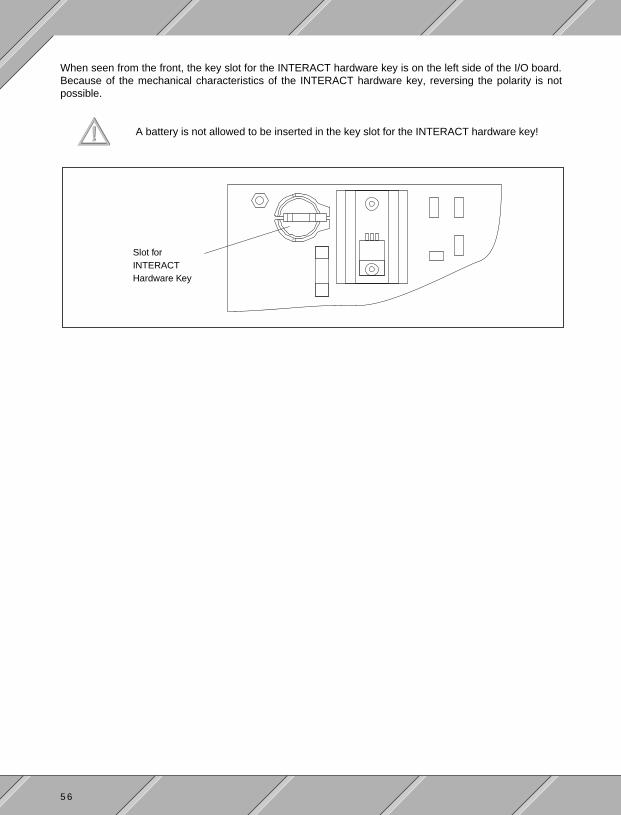
When seen from the front, the key slot for the INTERACT hardware key is on the left side of the I/O board.Because of the mechanical characteristics of the INTERACT hardware key, reversing the polarity is notpossible.
A battery is not allowed to be inserted in the key slot for the INTERACT hardware key!
Slot forINTERACTHardware Key
5 7
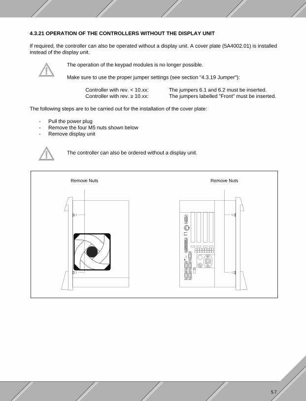
4.3.21 OPERATION OF THE CONTROLLERS WITHOUT THE DISPLAY UNIT
If required, the controller can also be operated without a display unit. A cover plate (5A4002.01) is installedinstead of the display unit.
The operation of the keypad modules is no longer possible.
Make sure to use the proper jumper settings (see section "4.3.19 Jumper"):
Controller with rev. < 10.xx: The jumpers 6.1 and 6.2 must be inserted.Controller with rev. ≥ 10.xx: The jumpers labelled "Front" must be inserted.
The following steps are to be carried out for the installation of the cover plate:
- Pull the power plug- Remove the four M5 nuts shown below- Remove display unit
The controller can also be ordered without a display unit.
Remove Nuts Remove Nuts

5 8
- In order to keep the disk drive from sticking out, it can be set further back in the housing:- Remove the four screws shown below which can be found on the bottom of the PROVIT 4000- Slide the disk drive backwards- Fasten the disk drive in the holes that are 15 mm farther back on the housing
Bottom View:
Remove Screws
- Place cover plate on the unit- Tighten the four M5 nuts
Holes for Installationin a 19" Frame
Cover Plate
Cutout for Disk Drive
Pressed-in Boltsfor Fastening toController Housing

5 9
4.4 HARD DISK
Two hard disks can be inserted in the hard disk frame of the PROVIT 4000 Industrial PC. Two hard disks areavailable from B&R with different memory capacities:
Model Number Hard Disk
5A4000.01 Memory Capacity ≥ 120 MBytes
5A4000.03 Memory Capacity ≥ 340 MBytes
Installation / Removal of a Hard Disk:
The housing cover must be removed in order to access the hard disk frame. The two screws shown below mustbe removed. The circle indicates the area where the hard disk frame can be found.
Remove Screws
Hard Disk Frame

6 0
The hard disk frame can be found on the left side of the I/O board. Two hard disks can be installed (see belowfor drive description). The hard disks are held in place with adhesive foam on the housing cover.
Plug-in Hard Diskfor Drive c:(Master)
Slot forDrive d:(Slave)
1) If only one hard disk is used, it has to be installed in the slot for drive c:.
2) The master hard disk is recognized automatically when two hard disks are used.
3) When the hard disk configuration is changed (e.g. installing a second hard disk), the BIOSsetup must be set to match the configuration. The BIOS setup is described in themotherboard user's manual.
4) See the following section for additional information:
- "2.4.1 Operation with One Hard Disk"- "2.4.2 Operation with Two Hard Disks"

6 1
4.5 POWER CABLE
The power cable is not contained with the delivery of the PROVIT 4000 Controller. It must be orderedseparately. The cable is approx. 1.8 m long.
Model Number Power Cable
9A0001.01 Cable with power plug
9A0001.02 Cable without power plug
The connection to the device is a screw on plug. The connection to the supply can be made either with a powerplug or attached directly.
Attention:
- A power plug with a ground contact must be used.- The connection may only be made by qualified personnel.- Make sure the installation meets the required electrical codes for your area.
Pin Assignments for Device Power Plug:
L (black) N (blue)
GND (yellow/green)
Plug Type:
HIRSCHMANN MK 311

6 2

6 3
SECTION 5SOFTWARE

6 4

6 5
5.1 B&R I/O AREA
I/O Address Bit Function
300h 0 LED 0 1)
1 LED 12 LED 23 LED 34 LED 45 LED 56 LED 67 LED 7
301h 0 LED 81 LED 92 LED 103 LED 114 LED 125 LED 136 LED 147 LED 15
302h 0 reserved1 reserved2 reserved3 reserved4 reserved5 CPU (proc.) Temp. Exceeded6 Display Temp. Exceeded7 Power Supply Temp. Exceeded
303h reserved
304h 0 LED F11 LED F22 LED F33 LED F44 LED F55 LED F66 LED F77 LED F8
I/O Address Bit Function
305h 0 LED F91 LED F102 reserved3 reserved4 reserved5 reserved6 reserved7 reserved
306h 0 reserved1 reserved2 reserved3 reserved4 reserved5 reserved6 Relay Output7 User LED
307h reserved
308h - 30Fh Coupling Area to Front
310h CAN Address
311h CAN Data
312h Watchdog Activation
313h - 31Fh reserved
1) See section "5.2 Key Illumination" for assignments.

6 6
5.2 KEY ILLUMINATION
5.2.1 FUNCTION KEY LEDS
5.2.2 SOFTKEY KEY LEDS
Key I/O Address Bit
F1 304h 0
F2 304h 1
F3 304h 2
F4 304h 3
F5 304h 4
F6 304h 5
F7 304h 6
F8 304h 7
F9 305h 0
F10 305h 1
0 1 2 3
4 5 6 7
8 9 10 11
12
13
14
15
Key
01234567
89
101112131415
I/O Address
300h300h300h300h300h300h300h300h
301h301h301h301h301h301h301h301h
Bit
01234567
01234567

6 7
5.3 USER LED
The User LED is controlled with the I/O address 306h, bit 7.
5.4 RELAY OUTPUT
Setting / resetting the relay output is done with I/O address 306h, bit 6.
5.5 TEMPERATURE MONITORING
The temperature is monitored at three measurement points. The three points are:
- CPU (processor)- Display- Power Supply
If the temperature at one of the three measurement points is too high, the respective bit is set and the TEMPLED on the display unit is turned on.
I/O Address Bit Function
302h 5 CPU (processor) Temp. Exceeded
6 Display Temp. Exceeded
7 Power Supply Temp. Exceeded

6 8

6 9
SECTION 6MEMORY ASSIGNMENTS

7 0

7 1
6.1 MEMORY ASSIGNMENTS
6.1.1 RAM - ADDRESS ASSIGNMENTS
RAM Address Function
000000h - 0003FFh Interrupt Vectors
000400h - 09FFFFh MS-DOS Program Area
0A0000h - 0AFFFFh VGA - Graphics
0B8000h - 0BBFFFh VGA - Text Mode
0C0000h - 0C7FFFh VGA - BIOS
0C8000h - 0EFFFFh free
0F0000h - 0FFFFFh BIOS
6.1.2 I/O ADDRESS ASSIGNMENTS
I/O Address Function
000h - 01Fh DMA Controller 1
020h - 03Fh Interrupt Controller 1
040h - 05Fh Timer
060h - 06Fh Keyboard Controller
070h - 07Fh Real Time Clock, NMI - Mask
080h - 09Fh Page Register
0A0h - 0BFh Interrupt Controller 2
0C0h - 0DFh DMA Controller 2
1F0h - 1F8h Hard Disk
278h - 27Fh LPT2 - INTERACT HW Key
2E8h - 2EFh COM4
2F8h - 2FFh COM2
300h - 31Fh B&R I/O Area, CAN Controller
378h - 37Fh LPT1
3B0h - 3BFh Monochrome Display
3C0h - 3DFh VGA Display
3E8h - 3EFh COM3
3F0h - 3F7h Disk Drive Controller
3F8h - 3FFh COM1
Controller with Rev. ≥≥≥≥≥ 10.xx
I/O Address Function
000h - 01Fh DMA Controller 1
020h - 03Fh Interrupt Controller 1
040h - 05Fh Timer
060h - 06Fh Keyboard Controller
070h - 07Fh Real Time Clock, NMI - Mask
080h - 09Fh Page Register
0A0h - 0BFh Interrupt Controller 2
0C0h - 0DFh DMA Controller 2
1F0h - 1F8h Hard Disk
2E8h - 2EFh COM4
2F8h - 2FFh COM2
300h - 31Fh B&R I/O Area, CAN Controller
378h - 37Fh LPT1
3B0h - 3BFh Monochrome Display
3C0h - 3DFh VGA Display
3E8h - 3EFh COM3
3F0h - 3F7h Disk Drive Controller
3F8h - 3FFh COM1
Controller with Rev. < 10.xx

7 2
6.1.3 INTERRUPTS
1) The interrupt may not be used by any of the four ISA bus slots.
2) Default setting. If the interrupt is free, it can be used by one of the four ISA bus slots.
IRQ No. Controller with Rev. < 10.xx Controller with Rev. ≥≥≥≥≥ 10.xx
IRQ0 System Timer System Timer
IRQ1 Keyboard Keyboard
IRQ2 Daisy Chained with Interrupt Controller 2 Daisy Chained with Interrupt Controller 2
IRQ3 COM2 or COM4 1) COM2, COM4 or free 2)
IRQ4 COM1 or COM3 1) COM1, COM3 or free 2)
IRQ5 reserved B&R 1) (possibly COM3 or COM4) free
IRQ6 Disk Drive (FDD) Disk Drive (FDD)
IRQ7 LPT1 1) (possibly COM3 or COM4) LPT1 or free
IRQ8 Real Time Clock Real Time Clock
IRQ9 free, IRQ2 for 16 Bit Computers free, IRQ2 for 16 Bit Computers
IRQ10 CAN (default) CAN or free 2)
IRQ11 free (possibly CAN) COM3, COM1 or free 2)
IRQ12 free (possibly CAN) COM4, COM2 or free 2)
IRQ13 Math Co-processor (FPU) Math Co-processor (FPU)
IRQ14 Hard Disk (HDD) Hard Disk (HDD)
IRQ15 free (possibly CAN) free

7 3
SECTION 7KEYPAD MODULES

7 4

7 5
7.1 OVERVIEW
16 Keys
Keys: 16
LEDs: 16
12 + 4 Keys
Keys: 16
LEDs: 4
Dummy Module
Keys: none
LEDs: none
E-Stop
E-Stop Button
Key Switch
Key Switch: 1
On/Off Switch: 1
Start / Stop
Keys: 2
Label Fields: 1
STOP
EM
ERGENCY
ON
OFF
987
4 5
1
6
2
0
3
E C
STARTSTOP
8 Keys
4 Keys
Keys: 8
LEDs: 4
Label Fields: 1
Keys: 4
LEDs: 4
Label Fields: 4
7 6
7.2 GENERAL INFORMATION
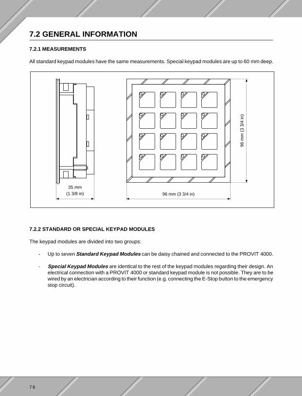
7.2.1 MEASUREMENTS
All standard keypad modules have the same measurements. Special keypad modules are up to 60 mm deep.
7.2.2 STANDARD OR SPECIAL KEYPAD MODULES
The keypad modules are divided into two groups:
- Up to seven Standard Keypad Modules can be daisy chained and connected to the PROVIT 4000.
- Special Keypad Modules are identical to the rest of the keypad modules regarding their design. Anelectrical connection with a PROVIT 4000 or standard keypad module is not possible. They are to bewired by an electrician according to their function (e.g. connecting the E-Stop button to the emergencystop circuit).
96 mm (3 3/4 in)
35 mm(1 3/8 in)
96m
m(3
3/4
in)

7 7
7.3 STANDARD KEYPAD MODULES
7.3.1 CONNECTION TO THE PROVIT 4000 OR OTHER KEYPAD MODULES
All standard keypad modules can be connected to the PROVIT 4000 or another keypad module with a shortconnection cable. There are two female connectors provided on the module for this purpose.The female connectors are labelled as input or output with triangle arrows! An output can be found on thePROVIT 4000 that can be connected with an input on a keypad module!
Make sure that an input is never connected to an input or an output is never connected to anoutput since this causes damage to the modules!
A
From PROVIT 4000or keypad module
To next keypad moduleor termination plug
Termination plug onthe last keypad module
View AB
Female connectors forconnecting the PROVIT 4000or another keypad module
View B
Keypad Module
PROVIT 4000
Keypad Module
TerminationPlug
Schematic:
InputOutput

7 8
7.3.2 RELATIONSHIP BETWEEN KEYPAD MODULE AND DISPLAY UNIT
The operation of the keypad modules is only possible if a display unit is installed. If a display unit with arev. < 20.16 is used, not all keypad modules can be connected to the PROVIT 4000.The following table contains an overview:
Keypad module Display Unit
Model Number Description Rev. < 20.16 Rev. ≥≥≥≥≥ 20.16
4E0010.01-090 16 Keys ● ●
4E0020.01-090 12 + 4 Keys ● ●
4E0030.01-090 8 Keys ● ●
4E0040.01-090 4 Keys ● ●
4E0011.01-090 16 Keys ●
4E0021.01-090 12 + 4 Keys ●
4E0031.01-090 8 Keys ●
4E0041.01-090 4 Keys ●
7 9
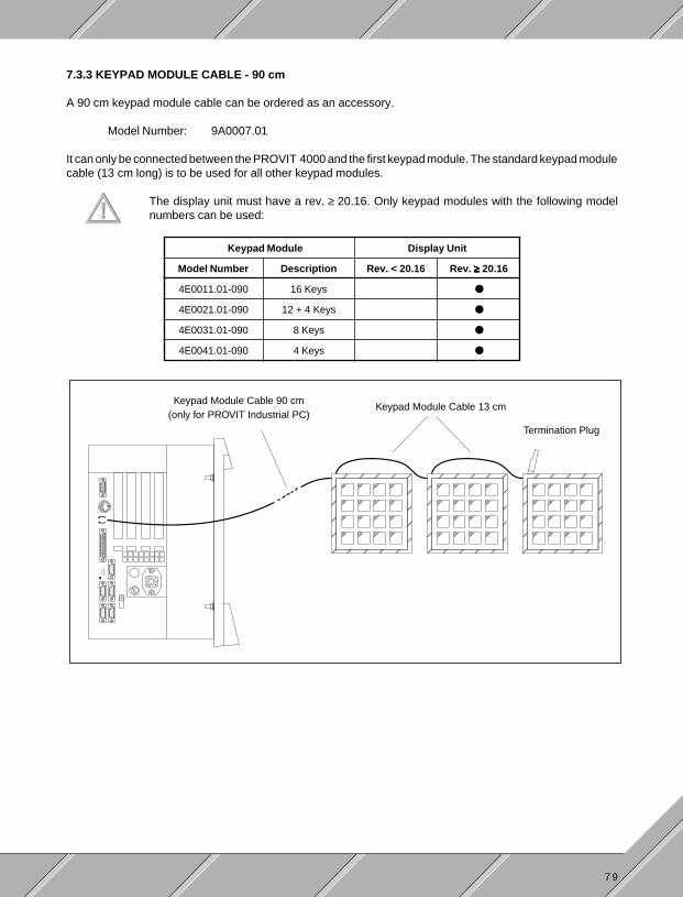
7.3.3 KEYPAD MODULE CABLE - 90 cm
A 90 cm keypad module cable can be ordered as an accessory.
Model Number: 9A0007.01
It can only be connected between the PROVIT 4000 and the first keypad module. The standard keypad modulecable (13 cm long) is to be used for all other keypad modules.
The display unit must have a rev. ≥ 20.16. Only keypad modules with the following modelnumbers can be used:
Keypad Module Display Unit
Model Number Description Rev. < 20.16 Rev. ≥≥≥≥≥ 20.16
4E0011.01-090 16 Keys ●
4E0021.01-090 12 + 4 Keys ●
4E0031.01-090 8 Keys ●
4E0041.01-090 4 Keys ●
Keypad Module Cable 90 cm(only for PROVIT Industrial PC)
Keypad Module Cable 13 cm
Termination Plug

8 0
7.3.4 KEYPAD MODULE 16 KEYS
Model Number 4E0011.01-090
Number of Keys 16 Short Stroke Keys
Number of LEDs 16 (yellow)
Labelling Can be labelled by the user
Temperature RangeOperation 0 to 50 °C (32 to 122 °F)Storage -20 to 60 °C (-4 to 140 °F)
Relative HumidityOperation 5 to 95 % (non-condensing)Storage 5 to 95 % (non-condensing)
Shock Conforms to IEC 68-2-27
Vibration Conforms to IEC 68-2-6
96 mm (3 3/4 in)
35 mm(1 3/8 in)
96m
m(3
3/4
in)

8 1
7.3.5 KEYPAD MODULE 12+4 KEYS
Model Number 4E0021.01-090
Number of Keys 16 Short Stroke Keys
Number of LEDs 4 (yellow)
Labelling 12 keys are labelled as number blocks4 keys can be labelled by the user
Temperature RangeOperation 0 to 50 °C (32 to 122 °F)Storage -20 to 60 °C (-4 to 140 °F)
Relative HumidityOperation 5 to 95 % (non-condensing)Storage 5 to 95 % (non-condensing)
Shock Conforms to IEC 68-2-27
Vibration Conforms to IEC 68-2-6
96 mm (3 3/4 in)
35 mm(1 3/8 in)
96m
m(3
3/4
in)
987
4 5
1
6
2
0
3
E C

8 2
7.3.6 KEYPAD MODULE 8 KEYS
Model Number 4E0031.01-090
Number of Keys 8 Short Stroke Keys
Number of LEDs 4 (yellow)
Labelling Can be labelled by the user
Label Fields One field for additional information
Temperature RangeOperation 0 to 50 °C (32 to 122 °F)Storage -20 to 60 °C (-4 to 140 °F)
Relative HumidityOperation 5 to 95 % (non-condensing)Storage 5 to 95 % (non-condensing)
Shock Conforms to IEC 68-2-27
Vibration Conforms to IEC 68-2-6
96 mm (3 3/4 in)
35 mm(1 3/8 in)
96m
m(3
3/4
in)

8 3
7.3.7 KEYPAD MODULE 4 KEYS
96 mm (3 3/4 in)
35 mm(1 3/8 in)
96m
m(3
3/4
in)
Model Number 4E0041.01-090
Number of Keys 4 Short Stroke Keys
Number of LEDs 4 (yellow)
Labelling Can be labelled by the user
Label Fields Four fields for additional information
Temperature RangeOperation 0 to 50 °C (32 to 122 °F)Storage -20 to 60 °C (-4 to 140 °F)
Relative HumidityOperation 5 to 95 % (non-condensing)Storage 5 to 95 % (non-condensing)
Shock Conforms to IEC 68-2-27
Vibration Conforms to IEC 68-2-6

8 4
7.4 SPECIAL KEYPAD MODULES
7.4.1 DUMMY MODULE
96 mm (3 3/4 in)
35 mm(1 3/8 in)
96m
m(3
3/4
in)
Model Number 4E0050.01-090
Number of Keys none
Number of LEDs none
Temperature RangeOperation 0 to 50 °C (32 to 122 °F)Storage -20 to 60 °C (-4 to 140 °F)
Relative HumidityOperation 5 to 95 % (non-condensing)Storage 5 to 95 % (non-condensing)
Shock Conforms to IEC 68-2-27
Vibration Conforms to IEC 68-2-6

8 5
7.4.2 E-STOP BUTTON
96 mm (3 3/4 in)
35 mm(1 3/8 in)
51 mm (2 in)
96m
m(3
3/4
in)
STOPE
M
ERGENCY
Model Number 4E0060.01-090
Number of Buttons 1 E-Stop Button
Temperature RangeOperation 0 to 50 °C (32 to 122 °F)Storage -20 to 60 °C (-4 to 140 °F)
Relative HumidityOperation 5 to 95 % (non-condensing)Storage 5 to 95 % (non-condensing)
Shock Conforms to IEC 68-2-27
Vibration Conforms to IEC 68-2-6

8 6
7.4.3 KEY SWITCH
Model Number 4E0070.01-090
Number of Switches 1 Key Switch1 On/Off Switch
Temperature RangeOperation 0 to 50 °C (32 to 122 °F)Storage -20 to 60 °C (-4 to 140 °F)
Relative HumidityOperation 5 to 95 % (non-condensing)Storage 5 to 95 % (non-condensing)
Shock Conforms to IEC 68-2-27
Vibration Conforms to IEC 68-2-6
96 mm (3 3/4 in)
35 mm(1 3/8 in)
96m
m(3
3/4
in)
ON
OFF
60mm (2 3/8 in)

8 7
7.4.4 START/STOP
Model Number 4E0080.01-090
Number of Keys 2 Keys (labelled START or STOP)
Temperature RangeOperation 0 to 50 °C (32 to 122 °F)Storage -20 to 60 °C (-4 to 140 °F)
Relative HumidityOperation 5 to 95 % (non-condensing)Storage 5 to 95 % (non-condensing)
Shock Conforms to IEC 68-2-27
Vibration Conforms to IEC 68-2-6
96 mm (3 3/4 in)
35mm(1 3/8 in)
96m
m(3
3/4
in)
STARTSTOP
60 mm (2 3/8 in)

8 8
7.5 ACCESSORIES
Accessories are delivered with each keypad module. They are packed together with the module.
Accessories Amount
Standard SpecialKeypad Module Keypad Module
Connection Elements 2 2
Cable Covers 2 2
Keypad Module Cable (connection to PROVIT 4000 or keypad module) 1 --
Clamps 2 2
Mounting Bolt Pins 1 1

8 9
SECTION 8OPTIONS AND ACCESSORIES

9 0

9 1
8.1 MEMORY EXPANSION
The PROVIT 4000 Industrial PC is equipped with SIMM slots for SIMM memory modules. The PROVIT 4000Industrial PCs are standardly equipped with the following amount of working memory:
Model Number 5C4000.01 5C4000.02 5C4000.03 5C4000.04
Working Memory 4 MBytes 4 MBytes 8 MBytes 8 MBytes(DRAM) (max. 16 MBytes) (max. 16 MBytes) (max. 64 MBytes) (max. 128 MBytes)
The maximum amount of working memory is shown in parentheses. The following SIMM memory modules arepresently available from B&R:
SIMMs from different manufacturers may not be mixed inside of a bank!
Which module sizes can be used with each other is described in the motherboard description.
The memory expansion modules are to be inserted into the designated SIMM slots on the motherboard. To getto the SIMM slots, the following steps must be taken:
- Pull power plug
- Remove display unit- Remove the four M5 nuts shown- Pull display unit out
Remove Nuts Remove Nuts
Model Number Memory Module
9A0004.01 1 MByte (1 MB * 9, 30 pin)
9A0004.02 4 MByte (4 MB * 9, 30 pin)
9A0004.03 4 MByte (1 MB * 36, 72 pin)
9A0004.04 16 MByte (4 MB * 36, 72 pin)

9 2
- Remove the 5 screws shown below
TopView:
Remove Screws
SideView:
RemoveScrews
Back View:
Remove Screws
FrontView:
Remove Screws

9 3
- Pull controller out
- A two pin plug is found on the bus board. It concerns the temperature sensor for the power supply. Thisplug must be removed.
- Remove the three screws shown below
Remove Plug
Remove Screws
- The motherboard must be folded back to access the SIMMs
- Change the SIMMs as described in the motherboard description
- The controller is reassembled in the opposite order
9 4
8.2 CENTRONICS/ONLINE CONVERTER
A CENTRONICS/Online Converter (model no. BRKAOL5-1) can be used to program the PLC processors ofthe B&R MINICONTROL or MULTICONTROL PLC systems. The CENTRONICS/Online Converter is con-nected to the LPT1 parallel interface of the PROVIT 4000. It allows a PLC processor to be programed.
8.3 PROFIBUS NETWORK CARD
The following setting is to be made: RAM Address: D0000h
8.4 ARCNET NETWORK CARD
Settings e.g. for SMC PC 130E: Interrupt number: IRQ2 (9)I/O Address: 2E0hRAM Address: D0000h
8.5 ETHERNET NETWORK CARD
The ETHERNET network card used must be NE2000 compatible.
The following settings are to made: Interrupt number: IRQ15I/O Address: 350h
8.6 ACCESSORIES
Description Consisting of Model Number
PROVIT MKEY Utilities Driver and configuration software for display unit 5S0001.01-090and keypad modules
Touch Screen Utilities Driver for the operation of the integrated Touch Screens 5S0003.01-090
PROVIT PC Card Utilities Phoenix PC Card Manager 5S0002.01-020
Accessory Set 4 screws M6, 4 nuts M6, 4 washes M6, 5A4003.014 lock washers M6, 4 cage nuts M6, 4 screwcovers, 2 pin terminal blocks
Legend Sheet Templates 10 sheets for labelling keys 5A4003.02
Power Cable (approx. 1.8 m long) with power plug 9A0001.01
without power plug 9A0001.02
Replacement Filters 10 replacement fan filters 5A4001.01
Cover Plate Cover plate for operation without display unit 5A4002.01

95
INDEX

96

97
AAccessories
Keypad Modules 88PROVIT 4000 15, 16, 94
Accessories 15, 16Air Circulation 29Application Keys 35ARCNET Network Card 94AT Keyboard (enhanced) 16, 50
BB&R I/O Area 65Brightness 34Bus 42
CCache Memory 41CAN Bus 46Card Installation 42CENTRONICS/Online Converter 94Checking the Delivery 19COM1 47COM2 47COM3 47COM4 47Configuration 21Contrast (LCD) 35Controller 41
CAN Bus 46Disk Drive 44Enhanced AT Keyboard Connection 50Fan 44Ground Connection 45INTERACT Hardware Key 55ISA Bus 42Jumper 51Keypad Module Connection 49Model Number 15, 41Motherboard 42Operation without Display Unit 57Parallel Interface LPT1 48Power Supply 43Processor 41Relay Output 48Serial Interfaces 47Technical Data 41Temperature Monitoring 50VGA Controller 45Watchdog 50
Cover Plate 57Cursor Keys 35
DDelivery Contents 19Digital Output 48, 67Disk Drive 44Disk Drive Cover 38Display
Brightness 34Contrast (LCD) 35Jumper 34Technical Data 34
Display UnitChanging 39Description 34Operation without Display Unit 57Touch Screen 40
Documentation 14Drive Cover 38Dummy Module (special keypad module) 84Dust Filter 20, 44
EE-Stop Button (special keypad module) 85English Key Code 36ETHERNET Network Card 94External Monitor 45
FFan 20, 44Fan Cover 20, 44Front Protection 41Function Keys 35Fuse 43
GGerman Key Code 36Ground Connection 45
HHard Disk
Configuration 21Duplication (MS-DOS) 24Frame 59Installation / Removal 59
Housing Cover 42Humidity 41

98
II/O Area 71
B&R I/O Area 65Installation
in 19" Frame 27in Door Cutout 28
Installation 25INTERACT Hardware Key 55Interfaces
CAN Bus 46COM1 47COM2 47COM3 47COM4 47Parallel Interface LPT1 48
International Key Code 36Interrupts 72ISA Bus 42
JJumper 34, 51
KKey Codes
English Key Code 36German Key Code 36International Key Code 36
Key Illumination 37, 66Key Labelling 37Key Switch (special keypad module) 86Keyboard
Configuration 35Enhanced AT Keyboard 16, 50Keypad Modules 49, 75Matrix Keyboard 35
Keypad Module Cable (90 cm) 79Keypad Modules 49, 75
12+4 Keys 8116 Keys 804 Keys 838 Keys 82Accessories 88Connecting Standard Keypad Modules 77Dummy Module 84E-Stop Switch 85Key Switch 86Keypad Module and Display Unit 78Keypad Module Cable (90 cm) 79Measurements and Remarks 76Overview 75Start/Stop 87
LLabelling the Keys 37LEDs
Key LEDs 37Status LEDs 37TEMP LED 67User LED 67
Legend Strips 37
MMath Co-processor 41Matrix Keyboard 35Measurements
Device Measurements 33Installation Measurements 28
Memory 41, 91Memory Assignments 71Memory Expansion 91MKEY Utilities Diskette 16, 35Model Numbers 15Monitor (external) 45Motherboard 42Mounting Holes for 19" Rack 38MS-DOS 14, 16
NNetwork Card
ARCNET 94ETHERNET 94PROFIBUS 16, 94
Number Keys 35
OOperating System 14Operating Temperature 41Operation without Display Unit 57Output (relay) 48, 67
PPacking Material 19Parallel Interface LPT1 48PC Card Utilities 16Pentium Setup 23Power Cable 20, 43, 61Power Plug 20, 61Power Supply 43Processor 41PROFIBUS Network Card 16, 94Protective Circuit for Relay Output 49PROVIT 4000 Industrial PC 12PROVIT MKEY Utilities 16, 35

99
RRelay Output 48, 67Replacement Filter 15Reset Button 38RS232
Interface Card 16Interfaces 47
RS485 Interface 47
SScrew Covers 29SIMM Memory Modules 91Slots 42Softkey Keys 35Start-up 17Start/Stop (special keypad module) 87Status LEDs 37Supply Voltage 20, 43
TTechnical Data
Controller 41Display Unit 34Keypad Modules 80
TEMP LED 67Temperature Monitoring 50, 67Temperature Range 41Terminal Block 20Termination Plug 77Touch Screen 40Touch Screen Utilities 16Transport Damage 19TTY Interface 47
UUnpacking 19User LED 67
VVGA Controller 45Voltage Selector 20, 43Voltage Selector Switch 20, 43
WWatchdog 50Weight 41Working Memory 41, 91

100


![HMIs and Industrial PCs [PDF, 3.67 MB]](https://static.fdocuments.us/doc/165x107/586b6ade1a28abb7768bd293/hmis-and-industrial-pcs-pdf-367-mb.jpg)