Providing low latency guarantees for slicing-ready 5G ... · the factors contributing to increased...
16
1 Providing low latency guarantees for slicing-ready 5G systems via two-level MAC scheduling Adlen Ksentini * , Pantelis A. Frangoudis * , Amogh PC † , Navid Nikaein * * EURECOM Sophia Antipolis - France, † IIT Hyderabad - India Email: * [email protected], † [email protected] Abstract 5G comes with the promise of sub-millisecond latency, which is critical for realizing an array of emerging Ultra-Reliable Low Latency Communication (URLLC) services, including industrial, enter- tainment, telemedicine, automotive, and tactile Internet applications. At the same time, slicing-ready 5G networks face the challenge of accommodating other heterogeneous coexisting services with different and potentially conflicting requirements. Providing latency and reliability guarantees to URLLC service slices is thus not trivial. We identify transmission scheduling at the Radio Access Network (RAN) level as a significant contributor to end-to-end latency when considering Network Slicing. In this direction, we propose a two-level MAC scheduling framework that can effectively handle uplink and downlink transmissions of network slices of different characteristics over a shared RAN, applying different per- slice scheduling policies, and focusing on reducing latency for URLLC services. Our scheme offers the necessary flexibility to dynamically manage radio resources to meet the stringent latency and reliability requirements of URLLC, as demonstrated by our simulation results. I. I NTRODUCTION 5G is assumed to not only increase the physical data rate, but also support a diverse set of new services coming from the vertical industry. These types of services are known to have different needs in terms of network performance, such as low latency access, high communication reliability and the support of massive numbers of devices. Therefore, the “one size fits all architecture” currently in use by 4G is no more sufficient. This led to think of new ways to design the network architecture at all system levels. Particularly, network slicing is envisioned as a solution to create virtual network instances sharing the common network infrastructure, and hence guarantee the heterogeneous requirements of the April 24, 2018 DRAFT
Transcript of Providing low latency guarantees for slicing-ready 5G ... · the factors contributing to increased...
1
Providing low latency guarantees for
slicing-ready 5G systems via two-level MAC
schedulingAdlen Ksentini∗, Pantelis A. Frangoudis∗, Amogh PC†, Navid Nikaein∗
∗ EURECOM Sophia Antipolis - France, † IIT Hyderabad - India
Email: ∗[email protected], †[email protected]
Abstract
5G comes with the promise of sub-millisecond latency, which is critical for realizing an array of
emerging Ultra-Reliable Low Latency Communication (URLLC) services, including industrial, enter-
tainment, telemedicine, automotive, and tactile Internet applications. At the same time, slicing-ready 5G
networks face the challenge of accommodating other heterogeneous coexisting services with different
and potentially conflicting requirements. Providing latency and reliability guarantees to URLLC service
slices is thus not trivial. We identify transmission scheduling at the Radio Access Network (RAN) level
as a significant contributor to end-to-end latency when considering Network Slicing. In this direction,
we propose a two-level MAC scheduling framework that can effectively handle uplink and downlink
transmissions of network slices of different characteristics over a shared RAN, applying different per-
slice scheduling policies, and focusing on reducing latency for URLLC services. Our scheme offers the
necessary flexibility to dynamically manage radio resources to meet the stringent latency and reliability
requirements of URLLC, as demonstrated by our simulation results.
I. INTRODUCTION
5G is assumed to not only increase the physical data rate, but also support a diverse set of new
services coming from the vertical industry. These types of services are known to have different needs
in terms of network performance, such as low latency access, high communication reliability and the
support of massive numbers of devices. Therefore, the “one size fits all architecture” currently in use
by 4G is no more sufficient. This led to think of new ways to design the network architecture at all
system levels. Particularly, network slicing is envisioned as a solution to create virtual network instances
sharing the common network infrastructure, and hence guarantee the heterogeneous requirements of the
April 24, 2018 DRAFT

2
vertical industry. Taking advantage of the advances in network virtualization, using NFV, SDN and cloud
computing, the 5G system is making network slicing a reality. In fact, recent European research projects1 2, as well as the 3GPP [1], have issued several 5G architectures that natively support network slicing.
One common agreement is to classify slices into three types: (i) extreme Mobile Broadband (xMBB),
which requires high data rates, even in dense areas, (ii) Ultra-Reliable Low-Latency Communication
(URLLC), and (iii) massive Machine-Type Communication (mMTC) to enable IoT services.
The URLLC service category is envisioned to support automotive industry services, such as vehicular
networks and industry 4.0, and other services such as cloud robotics as well as tactile Internet. All
these services require low-latency access. For instance, the most stringent requirement on the end-to-end
latency for tactile Internet services may be 1 ms. End-to-end latency within a slice connection is mainly
composed of (i) access to the service (typically hosted in the Cloud) latency, (ii) core network latency, (iii)
fronthaul/backhaul latency, and (i) Radio Access Network (RAN) latency. While the fronthaul/backhaul
and core network latencies could be reduced using high capacity links, RAN and service access latencies
represent the main challenge to satisfy URLLC requirements. Indeed, the RAN is seen as the bottleneck
of the system, where different important functions are shared among slices, such as Medium Access
Control (MAC) scheduling and low-level Radio-Link Control (RLC) functions. At the same time, access
to the cloud service is not under the full control of the network operator as traffic passes via external
routers. One emerging solution to deal with cloud access latency is to locate the service at the edge of the
network, following the Multi-access Edge Computing (MEC) concept. However, RAN latency persists
and efficient solutions are required, particularly in network-slicing-ready networks, where slices have to
share common RAN functions.
In this article, we propose a novel MAC scheduling mechanism, covering both the uplink (UL) and the
downlink (DL), to reduce access latency for URLLC slices, even with radio resources shared among
them. The proposed scheme relies on the concept of two-level scheduling introduced in [3]: (i) a first
level of UE scheduling is slice-specific, i.e. carried out by a slice-specific scheduler; (ii) a second level is
responsible for inter-slice resource partitioning, that is, sharing the channel among slices and enforcing the
scheduling decisions of the first level, using the Slice-Dedicated Bandwidth (SDB) policy communicated
by the Slice Orchestrator (SO). The improved two-level scheduler presented in this paper provides more
details on how URLLC requirements can be met, and covers not only DL but also UL communication.
The obtained simulation results demonstrate that the SDB as defined in [3] should be updated in order to
1H2020 EU-Japan 5G!Pagoda, https://5g-pagoda.aalto.fi/, last access November 2017.2H2020 5GPPP 5Gexchange (5Gex), http://www.5gex.eu/, last access November 2017.
DRAFT April 24, 2018

3
include not only the amount of resources dedicated to a slice, but also the number of active UEs tolerated
per slice as well as the Modulation and Coding Scheme (MCS) to be used. Particularly, the latter two
are very important to be appropriately configured in order to guarantee low latency and reliability for a
URLLC slice.
The article is organized as follows: Section II provides an overview of the factors contributing to latency
and state-of-the art solutions to limit it in a 5G context. Our proposed approach is presented in Section III
and evaluated via simulation in Section IV. We conclude the article in Section V.
II. RELATED WORK
URLLC slices require low-latency access to remote services. It is important to understand what are
the factors contributing to increased end-to-end latency in 5G (featuring network slicing), and how it
could be reduced to fulfill URLLC requirements. This section reviews the root causes and the solutions
to reduce separately each latency component.
A. Access to the service
This latency component is related to the time needed to access the service endpoint from the mobile
network. In the typical case of a cloud-hosted service, this latency consists in the delay to access a
service from the Packet Data Gateway (P-GW) to the cloud provider, which, to most cloud platforms, is
in the order of 200 ms [2] and may significantly vary due to fluctuations in network conditions. This is
intolerable for URLLC services. Large cloud providers are thus proposing to build a dedicated network
connection with user networks (e.g., Amazon’s direct connect service). However, such a type of solution
suffers from a lack of Service Level Agreement (SLA) support with network operators. Another trend
to reduce cloud service access latency is to locate storage and computing resources at the network edge
(i.e., Edge Computing). Similar to the case of Content Delivery Networks (CDN), which has known a
huge success by using caching techniques, locating computing resources at the edge may reduce latency
considerably (less than 50 ms) [5]. Edge computing is an emerging concept, where two technologies are
well established: Fog computing and MEC. In the former, computing resources are located at (or close)
to edge routers, while in the latter they are located close to eNodeBs or Core Networks. Fog is highly
pushed by large industrial players, while MEC is being standardized by the ETSI. For more details on
edge computing solutions and the differences between MEC and Fog, the reader may refer to [4].
B. Fronthaul/Backhaul and core network
This type of latency is mainly related to the capacity of the links connecting the core network to the
RAN, the core network to the Internet, and more recently, the Baseband Unit (BBU) to Remote Radio
April 24, 2018 DRAFT

4
Fig. 1: Relation of functional split with timing.
Heads (RRH) (fronthaul links). While the latency caused by the links connecting the mobile network
to the Internet is negligible, the latency of the fronthaul links may highly impact the end-to-end delay.
Indeed, with recent advances in Cloud RAN and Centralized RAN (C-RAN), the fronthaul/backhaul links
become vital as they should ensure the transport of radio signals with a low-latency connection from the
RRH to the BBU, particularly in the context of the RAN functional split. The latter refers to the choice
of the RAN functions that should be run at a central unit (BBU) and those that should be run at the
RRHs. The choice between running some RAN functions in the RHH and some in the BBU shall depend
on their latency tolerance and the fronthaul capacity (i.e., bandwidth and latency). Fig. 1 illustrates a
high level view of RAN functions, their relation with latency, and whether they belong to the control
DRAFT April 24, 2018

5
or data plane. Besides, the IEEE NGFI (Next Generation Fronthaul Interface) group has studied seven
options to split RAN functions between BBU and RRH. In [10], these options are studied and compared
in terms of interface bandwidth and latency. Recently, the 3GPP, via the RAN3 study group, has started
discussing the 5G RAN architecture featuring functional split [9]. In the 3GPP design, the BBU will
consist of two new entities named the Central Unit (CU), which may host time-tolerant functions like
PDCP, and the Distributed Unit (DU) that performs time-critical functions, such as MAC and/or part of
the physical layer functions. Note that the DUs are envisioned to be located close to the network edges.
Accordingly, the flexible functional split can highly impact the performance of network slicing, with the
optimal split being different for specific slices considering service-specific constraints. For example, a
URLLC slice may require that most RAN functions run on DU to fulfill latency requirements, while
in an xMBB slice, a higher centralization can enhance the throughput by aggregating RRHs enabling,
e.g., Coordinated Multipoint (CoMP) transmissions. In addition to the delay due to the functional split,
the use of Ethernet as a fronthaul can also introduce latency. In [7], the authors studied the impact of
packetisation (i.e., the time needed to create an Ethernet packet to convey a radio signal) on the latency
in the context of an Ethernet-based fronthaul. They demonstrated that according to the functional split the
impact of packetisation on latency is different. For each split option, a packetisation method is deduced
aiming at reducing latency.
C. RAN latency
RAN latency is heavily contributing to end-to-end latency. Although it is assumed that slice Network
Functions (NF) are isolated and may not be impacted by the presence of other slices, most important
channel access-related functions are shared among all slices. Indeed, it is agreed [3], [8] that MAC
scheduling should be a common NF at the MAC level as it is in charge of sharing the common radio
resources among slices (i.e., UEs) in both directions, uplink and downlink.
RAN latency is composed of the time needed to access the channel (random access channel procedure),
and the latency associated with UE scheduling procedures. The random access channel is used by a UE
to send Sending Reports (SR) to the eNodeB to indicate that data are in its uplink buffer, or to attach
to the network. When the number of active UEs competing for channel access increases, the collision
number increases as well, leading to considerably increased latency as UEs should defer their transmission
attempts by waiting for a random amount of time (back-off). For instance, if we consider one sub-frame
that provides 64 preambles for random access,3 and if 1000 UEs are contending for the channel with 30
3The preamble is a random access channel signal with a specific signature sent by a UE. Up to 64 distinct preambles are
available in a cell. If two users select and simultaneously transmit the same preamble, a collision occurs.
April 24, 2018 DRAFT
6
transmission attempts per second, then the collision probability reaches 0.99, which significantly increases
channel access latency. Such a situation mostly occurs in the case of mMTC. Hence, several works have
been proposed to improve the random channel access procedure aiming at supporting mMTC, while
reducing the impact on normal UE traffic. In [15], the authors propose an analytical model to predict
MTC traffic, which is then used to propose a new paging mechanism to organize the channel access of
a group of MTC devices (i.e., based on the service). This significantly reduces the collision probability,
hence reducing channel access latency. Another solution proposed in [3] involves using a semi-persistent
uplink scheduler for MTC, adding a new Radio Resource Control (RRC) state (RRC connected, UE
inactive), which allows to keep a state for inactive MTC devices (assumed to be active periodically).
Consequently, this avoids the use of the random access procedure each time a device has data to send,
as the radio bearer is always active at the RAN level.
The second component of the RAN latency is the delay introduced by the DL and UL scheduling
procedures. The particular context of network slicing introduces a new challenge on latency, as the
channel resources should be shared among slices with different requirements (latency, bandwidth, etc.),
using a common scheduling algorithm. Several works have been devised for delay-based scheduling,
featuring DL and UL scheduling procedures. For downlink scheduling algorithms, the reader is referred
to [11] and [13]. Regarding the uplink, the most notable work is proposed in [12]. The authors propose
a new uplink scheduling process that uses an analytical model to estimate packet latency, using the
Buffer Status Report (BSR) mechanism provided by LTE, and solves an optimization problem which
aims to minimize UE delays. However, all these solutions are not defined for the case of network slicing,
which requires a joint scheduling algorithm as specified in [14]. The latter formulates a multi-objective
optimization problem in order to satisfy all slice requirements at the same time. However, due to the
problem’s complexity, it is very hard to derive the optimal scheduling solution during one Transmission
Time Interval (TTI).
III. PROPOSED SOLUTION
Even by employing solutions to reduce the first three latency components (i.e. cloud access, fronthaul,
core network), it is still difficult to fulfill the requirements of a URLLC service without reducing as much
as possible the latency associated with RAN access. Although the random access channel procedure could
be improved by applying techniques described in the previous section, the scheduling process remains the
system’s bottleneck, as potentially conflicting slice-specific requirements should be satisfied while sharing
the radio resources among slices. In this article, we focus on providing a MAC scheduling solution in
order to sustain URLLC requirements in the context of a slicing-ready 5G network. As stated earlier,
DRAFT April 24, 2018

7
Fig. 2: System Model
state-of-the-art MAC schedulers for delay sensitive applications operate in one step, requiring the solution
of a complex and multi-objective optimization problem. Contrary, we favor a solution based on two-level
scheduling so as to relax the complexity of the MAC scheduler in both directions.
A. Overview of the two-level MAC scheduling
A global view of the envisioned architecture, where the two-level scheduling process operates, is
illustrated in Fig. 2. The figure shows a case of different slices running over a shared radio channel.
The different involved entities are: (i) the Slice Orchestrator (SO) that manages the lifecycle (creation,
configuration and management) of network slices; (ii) Software-Defined RAN, composed by an eNodeB
hosting an agent, and a remote controller that configures and manages the eNodeB using a southbound
protocol. Each slice is composed of a certain number of RAN functions depending on its requirements.
Note that even though low RLC is shown as common, it could be run within a slice as a NF. However,
unlike high RLC, it cannot be tailored to a specific slice. Each slice has its own NF to schedule its UEs,
in both UL and DL. This function is noted as Slice Specific Resource Management (SSRM). The SSRM
of each slice may run a different scheduling algorithm. The result of each SSRM is an assignment of
virtual Resource Blocks (vRB) to UEs. Note that the vRB number is not limited, and its size should
be aligned with the physical Resource Block (pRB) size. Based on the communication direction, the
SSRM algorithm is different. The SSRM for the DL direction is based on the logical channel queue of
April 24, 2018 DRAFT

8
UEs, while in the UL direction it is based on the periodic Buffer Status Reports (BSR). The common
MAC scheduling NF (Common Resource Management - CRM) is responsible to translate the vRB-UEs
assignment into a pRB-UE assignment. Since there is a limited number of pRBs, the CRM performs
inter-slice resource partitioning by limiting the pRB-UE assignment according to the SDB policy (pRB
percentage dedicated to a slice), which is communicated by the Slice Orchestrator (SO) when instantiating
a new slice at the RAN level. Note that the SO is communicating with the eNodeB using a southbound
protocol like FlexRAN [6]. FlexRAN is a framework to enable a Software Defined RAN. An agent hosted
in the eNodeB communicates with a remote controller, using the FlexRAN southbound API in order to
dynamically (re-)configure and get information on the RAN. If a user participates in multiple different
slices, it maintains a different logical channel per slice. At the eNodeB level, each slice is associated
with its respective set of logical channels, one per UE. The group of logical channels that corresponds
to a slice is collectively managed by a specific SSRM. Readers may refer to [3] for more details on how
the network slice is enforced using FlexRAN.
B. The proposed scheduling algorithm
1) SSRM downlink scheduling: The SSRM process manages the scheduling of UE packets belonging
to its slice. We distinguish between the SSRM for the UL and the DL directions. As in [3], the SSRM
scheduling algorithm for xMBB slices is based on proportional fair (PF) queuing, while for mMTC
it may be based on a semi-persistent algorithm, if the communication timing of the MTC devices is
known, or on the PF algorithm. However, it is well-known that MTC traffic is uplink dominant. Hence
the UL scheduler should be more finely defined than the DL scheduler. On the other hand, for URLLC
slices, the PF algorithm does not appear to be appropriate. This leads us to consider a delay-oriented
scheduling algorithm, or a combination of a delay-based algorithm and PF to both address latency and
increase the channel usage. However, in the latter case, a specific tuning should be achieved to avoid
violating delay requirements. We thus propose that the SSRM of URLLC uses the Earliest Deadline First
scheduling algorithm. First, the SSRM starts by mixing all the UE queues belonging to a URLLC slice,
which will create a single queue per slice. Then, the queue is sorted by placing the packets having their
delays close to the deadline first. Therefore, the head of the queue corresponds to the packet (UE) that
shall be scheduled first. The deadline represents the maximum tolerated delay by the URLLC slice. This
information is communicated by the SO to the eNodeB at slice instantiation time using the FlexRAN
protocol. Finally, the SSRM proposes a vRB-to-UE allocation sorted by priority (i.e., delays).
2) SSRM uplink scheduling: In the uplink direction, the SSRM process is different. Unlike DL, to
allocate vRBs to UEs, the SSRM relies on the BSR defined by LTE, which allows the UE to indicate
DRAFT April 24, 2018

9
its buffer size in the uplink direction. The BSR is sent by a UE either periodically or after the UE has
sent a Scheduling Request (SR) and has gotten a grant from the eNodeB to send a packet. Therefore, we
propose to periodically (TTI-based) organize the received BSRs in a matrix indexed by the UE and slice
identifiers. For that, we introduce a three-dimensional matrix C, where C(s, u, t) represents the BSR sent
by UE u belonging to slice s at time instant t. We also introduce γu,s(t) = C(u, s, t) − C(u, s, t − 1),
which represents the difference between the size of the buffer at t and t − 1. If γu,s is positive, it
means that even if the UE was served during the precedent period, it may still have some data in its
buffer from that period. For xMBB and URLLC slices, the UEs are sorted according to γ; the higher
the value of γ, the higher the UE priority. The SSRM then proceeds to allocate vRBs to UEs. mMTC
traffic, which is uplink-dominant, requires a specific algorithm. We can either adopt the solution in [3]
by considering a semi-persistent scheduler (SPS) and hence add a new RRC state, or use a specific
SSRM-UL for mMTC. In case of using SPS, the SO communicates the timing to the CRM, and the latter
dedicates specific resources to the mMTC slice during the activation period, avoiding high contention
on the channel. Therefore, the mMTC slices will not have a SSRM network function. In case of using
an SSRM dedicated to mMTC, the usage of BSR reports may overload the channel, due to the massive
number of MTC connections. Therefore, we propose to deactivate the BSR report for MTCs; the SSRM
will use only the SR report sent by MTC devices, and apply a simple Round Robin (RR) scheduling
algorithm, as it is assumed that there is no QoS requirement for the mMTC service.
3) Common Resource Manager: The first step of the CRM is similar in both communication directions.
The CRM begins by serving the URLLC slices. This process ends either if the SDB defined for a URLLC
slice has been reached or when the allocation proposed by the SSRM scheduler (for both directions) has
been entirely treated. After having served all the URLLC slices, the CRM moves to the remaining slices
(i.e., xMBB and/or mMTC). When this process ends and there are still some remaining pRBs available,
then the CRM gives priority to the URLLC slices (if these slices have not reached their SDB). Here,
a different strategy is followed between the UL and DL. For the DL direction, we propose that all the
waiting UE/vRB allocations of URLLC, which have not consumed their SDB, are sorted and merged
into one unique queue. In order to deal with different URLLC requirements (i.e., different maximum
tolerated delay), we introduce δv,i =MaxDelay(i)−waiting timev
MaxDelay(i) , which corresponds to the proportion of
time remaining for vRB v allocated to slice i before reaching the maximum delay constraint specified
for the latter. This implies that if δv,i is close to zero, then the system is close to violating the delay
requirement. In the UL direction, all URLLC queues are mixed and sorted according to the value of γ;
those having higher value of γ are served first. By using γ and δ to sort the different SSRM (URLLC)
assignment in two queues (one for UL and one for DL), we tackle the difference in the delay requirements
April 24, 2018 DRAFT

10
of coexisting URLLC slices. The CRM then serves the first UE/vRB until either the allocation list is
empty or all slices have consumed their SDB or no more pRBs are free. In any cases, the loop is ended
after the second iteration, in order to ensure that the SSRM and CRM scheduling can be done during
a TTI interval, i.e. 1ms. Indeed, the two-level scheduler’s complexity is kept low, as the SSRM can be
run on parallel, and the CRM complexity is proportional to the number of Slices. Note that to increase
reliability, all the scheduled pRBs of URLLC slices are using a robust MCS.
C. URLLC management
In order to ensure that URLLC slices are optimally served, the SO, using the FlexRAN protocol,
periodically requests statistics from the RAN (eNodeBs) about the packets that have violated their deadline
requirement. This information allows the SO to monitor the status of URLLC and dynamically optimize
its operation. If the ratio of packets that do not meet their latency requirement is high, the cause might
be that either the URLLC slice does not have enough resources (the SDB is low) or is using large
packets. In the latter case, the use of a robust MCS may increase the time needed to transmit a packet,
in turn causing queuing delays to increase (increased γ). Therefore, depending on this information, the
SO may request to increase the SDB of the URLCC slice or, in the case of large packets, to use the CQI
information to derive the MCS.4 However, the optimal MCS from a delay perspective may not coincide
with the optimal one in terms of reliability. This reveals an interesting trade-off that the SO needs to
address.
IV. PERFORMANCE EVALUATION
A. Results
We present results on the performance of our two-level scheduler after implementing it in Matlab. Our
objective is to demonstrate how our two-level scheduler is able to ensure URLLC requirements in terms
of latency, while guaranteeing throughput to xMBB and mMTC slices. As UL and DL results are similar,
we only present the DL ones, since they can offer a good insight on the scheduler performance. The
reader may refer to [6] about performance issues with respect to the interaction of the SO (controller)
with the eNodeB agent.
We begin with a scenario where one URLLC, one xMBB and one mMTC slices are deployed. For both
xMBB and mMTC slices, a proportionally fair SSRM is used. Each slice has 5 active UEs. We used
a channel bandwidth of 5 Mhz, allowing to have 25 pRBs. The scheduling interval (i.e., TTI) is 1 ms.
4A table mapping CQI to MCS values for LTE is included in the 3GPP Technical Specification 36.213.
DRAFT April 24, 2018

11
Parameter Value
Slices [URLLC,xMBB,mMTC]
Average Packet Size [100/1000,1400,20] Bytes
SDB between [0,20] seconds [33,33,33]% [URLLC,xMBB,mMTC]
SDB between [20,40] seconds [60,20,20]% [URLLC,xMBB,mMTC]
SDB between [40,60] seconds [20,40,40]% [URLLC,xMBB,mMTC]
Bandwidth 5 Mhz
Transmission Time Interval (TTI) 1 ms
Inter-arrival time of packets [20, 25, 50] ms
TABLE I: Simulation parameters
0 1 2 3 4 5 6 7
Time (ms) ×10 4
0
500
1000
1500
2000
2500
3000
3500
4000
4500
5000
Thro
ughput (K
bps)
Throughput (Small Packets)
uRLLCxMBBmMTC
(a) Small packet size.
0 1 2 3 4 5 6 7
Time (ms) ×10 4
0
1000
2000
3000
4000
5000
6000
7000
8000
Thro
ughput (K
bps)
Throughput (Large Packets)
uRLLCxMBBmMTC
(b) Large packet size.
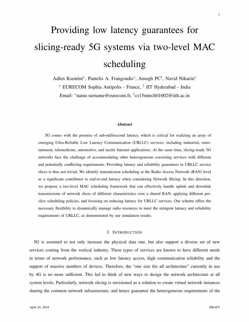
Fig. 3: Throughput vs. time.
The simulation is divided into three periods (resource partitioning windows). In the first period, each
slice gets an equal share of the channel; the SDB is fixed to 33% of the system resources for each slice.
During the second period, we increase the resources of the URLLC slice to 60%. In the last period, we
reduce the resources of the URLLC slice to 20%.
The objective is to show how the two-level scheduler is able to satisfy the slice requirements in terms
of bandwidth, latency and reliability, and the impact of SDB as well as the number of active UEs per slice
on the performance. Table I summarizes the simulation parameters and the considered scenario. Fig. 3
shows the evolution of the throughput regarding the simulated time, when changing dynamically (at t=20 s
and t=40 s) the SDB value of each slice. Fig. 3(a) shows the case of running a URLLC application with
a small packet size, while Fig. 3(b) illustrates the case of a URLLC application using a large packet size.
We clearly see that the proposed two-level scheduler is able to react to the dynamic change of SDB by
ensuring more throughput if the SDB is increased, and inversely. Moreover, we remark that the packet
April 24, 2018 DRAFT

12
2 4 6 8 10 12 14 16 18 20
Delay (ms)
0
0.1
0.2
0.3
0.4
0.5
0.6
0.7
0.8
0.9
1
CD
F
Delay (0-20)s
uRLLC1-Large Packet
(Delay Based) Most - Robust MCS
uRLLC2-Small Packet
(Delay Based) Most - Robust MCS
uRLLC1-Large Packet (PF)
uRLLC2-Small Packet (PF)
uRLLC1-Large Packet
(Delay Based) CQI-MCS
uRLLC2-Small Packet
(Delay Based) CQI-MCS
(a) from t=0s to t=20s
0 2 4 6 8 10 12 14 16 18 20
Delay (ms)
0
0.1
0.2
0.3
0.4
0.5
0.6
0.7
0.8
0.9
1
CD
F
Delay (20-40)s
uRLLC1-Large Packet (Delay Based) Most - Robust MCS
uRLLC2-Small Packet (Delay Based) Most - Robust MCS
uRLLC1-Large Packet (PF)
uRLLC2-Small Packet (PF)
uRLLC1-Large Packet (Delay Based) CQI-MCS
uRLLC2-Small Packet (Delay Based) CQI-MCS
(b) from t=20s to t=40s
2 4 6 8 10 12 14 16 18 20
Delay (ms)
0
0.1
0.2
0.3
0.4
0.5
0.6
0.7
0.8
0.9
1
CD
F
Delay (40-60)s
uRLLC1-Large Packet
(Delay Based) Most - Robust MCS
uRLLC2-Small Packet
(Delay Based) Most - Robust MCS
uRLLC1-Large Packet (PF)
uRLLC2-Small Packet (PF)
uRLLC1-Large Packet
(Delay Based) CQI-MCS
uRLLC2-Small Packet
(Delay Based) CQI-MCS
(c) from t=40s to t=60s
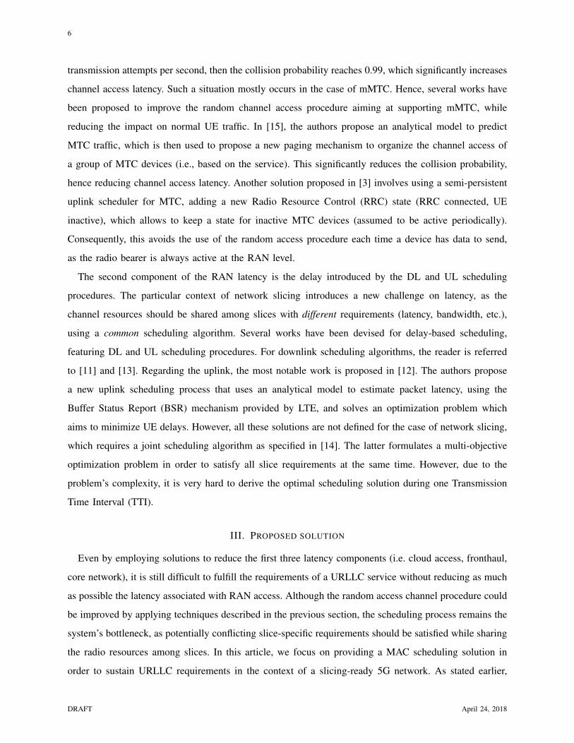
Fig. 4: CDF of latency
size (in case of URLLC) impacts the throughput performance; the throughput is higher when using large
packet sizes.
However, for URLLC slices it is more important to focus on the latency performance; Fig. 4 illustrates
the CDF of latency for URLLC packets, and for each of the three periods. Here, we compared a delay-
based SSRM to a PF-based SSRM. For each SSRM, we considered small and large packet size (100 and
1000 bytes). Moreover, for the delay-based SSRM we considered the use of robust MCS (i.e., increased
reliability) and CQI-based MCS (i.e., less reliability but maximizing the spectrum usage). Note that the
latency represents the needed time for a packet to be scheduled, i.e., the time spent by a packet in the
SSRM queue before being scheduled. We remark that the delay-based SSRM always outperforms PF-
based SSRM, by ensuring lower latency. Furthermore, we observe that using small packet sizes allows to
reduce the latency in all the cases. This is explained by the fact that small packets require less pRBs to
be transmitted, even when using robust MCS (the case of delay-based SSRM). Since the SDB is fixed for
a URLLC slice, using small packets requires less pRBs, and hence more pRBs are available. This allows
to reduce queuing delays, as more packets are scheduled during a TTI. Also, we confirm that the SDB
DRAFT April 24, 2018

13
value has a great impact on latency performance; increasing the SDB of the URLLC slice (between the
20th and 40th second) permits to considerably reduce latency. For instance, the latency is less than 3 ms
and 5 ms, for delay-based SSRM with small and large packet sizes, respectively. Regarding reliability,
we notice that ensuring it (using a robust MCS) comes with increased latency. Indeed, we observe from
the figure that using CQI-based MCS reduces latency, as the throughput is maximized. Therefore, there
is a need to find a trade-off between ensuring reliability and reducing latency, which is a subject of our
ongoing research.
Having seen the impact of both SDB and packet size on latency performance, we investigate the impact
5
10
15
20
25
30
10
25
50
75
100
0
10
20
30
40
Number of UEs
Small packets, delay−based scheduler
SDB (%)
De
lay (
ms)
(a) Small packet size.
5
10
15
20
25
30
10
25
50
75
100
0
10
20
30
40
Number of UEs
Large packets, delay−based scheduler
SDB (%)
De
lay (
ms)
(b) Large packet size.
Fig. 5: Latency vs. number of UE and SDB.
of the number of active UEs on a URLLC slice. Fig 5 (a) and (b) indicate the latency with respect to
the number of UEs and the value of SDB, when using a small and a large packet size, respectively. We
clearly remark that increasing the number of UEs per slice increases latency, as a result of increased
queuing delays. Furthermore, we observe that increasing the SDB, even when a high number of UEs are
active, allows to keep latency low. For instance, an SDB of 50% enables to keep latency to less than
5 ms when 25 UEs are active. However, we observe that there is a number of UEs beyond which latency
increases exponentially for each SDB value. Finally, we observe that reducing the packet size always
reduces latency.
It worth noting that using high bandwidth (more pRBs) will indicate the same results trend. The only
difference will be the threshold of the number of UEs beyond which the latency increases exponentially.
April 24, 2018 DRAFT

14
B. Discussion
From the obtained results, we clearly observed that the two-level scheduler is able to satisfy the different
requirements of the envisioned 5G slices at the MAC scheduling level. Particularly, it allows to guarantee
the strict latency requirements of URLLC slices. However, there is a need to carefully dimension the
SDB value, and use an admission control scheme to limit the number of UE per URLLC slice. Indeed,
we demonstrated that keeping latency under a certain value requires to not exceed a certain number
of UEs per slice, for a specific SDB value and packet size. Therefore, we propose that the SO, when
instantiating a URLLC slice, sends the SDB value along with the maximum number of supported UEs
in order to guarantee a maximum latency value. The SDB format thus has to be extended to include not
only the bandwidth share (amount of resources dedicated to a slice), but also the maximum number of
UEs and the mode of selecting the MCS to be applied (i.e., robust-only or CQI-based). We should finally
note that our solution operates purely at the MAC scheduling level. As such, further research could be
directed towards complementing it with lower-layer schemes, including HARQ.
V. CONCLUSION
We presented a two-level MAC scheduling framework tailored to slicing-ready 5G systems, specifi-
cally designed to accommodate the delay and reliability requirements of URLLC, while respecting the
heterogeneous needs of coexisting xMBB and mMTC services. We demonstrated the flexibility of our
design to carry out dynamic slice management decisions and its capability to improve on timely data
delivery, which is an important step towards providing latency guarantees for URLLC. One of the future
directions of this work is to study the impact of very small TTI (125 µs), as expected in 5G, as it will
introduce more burden on the scheduling process at the MAC layer.
ACKNOWLEDGEMENTS
This work is partially funded by the European Framework Program under H2020 grant agreement No.
723172 5G!Pagoda project
REFERENCES
[1] 3GPP TS 23.501 “System Architecture for the 5G System,” Release 15.
[2] V. Uhlir et al. “Latency-based benchmarking of cloud service providers,” in Proc. 9th ACM International Conference on
Utility and Cloud Computing (UCC), 2016.
[3] A. Ksentini and N. Nikaein, “Towards enforcing Network Slicing on RAN: Flexibility and Resources abstraction,” in IEEE
Communications Magazine, June 2017.
DRAFT April 24, 2018

15
[4] Y. Mao et al. “A Survey on Mobile Edge Computing: The Communication Perspective,” IEEE Communications Surveys &
Tutorials (COMST) Volume: 19, Issue: 4, Fourthquarter 2017.
[5] A. Huang et al. “Low Latency MEC Framework for SDN-based LTE/LTE-A Networks,” in Proc. IEEE ICC, 2017, Paris,
France.
[6] X. Foukas et al. “FlexRAN: A Flexible and Programmable Platform for Software-Defined Radio Access Networks,” in Proc.
of ACM CoNEXT, 2016.
[7] C-Y. Chang et al. “Impact of Packetization and Functional Split on C-RAN Fronthaul Performance,” in Proc. IEEE ICC,
2016.
[8] P. Rost et al. “Network Slicing to Enable Scalability and Flexibility in 5G Mobile Networks,” IEEE Communications
Magazine, Vol. 55, Issue 5, May 2017.
[9] 3GPP TSG RAN2 Tdoc R21700637 “Summary of RAN3 status on CU-DU split Option 2 and Option 3, and questions
issues for RAN2,” RAN3 NR Rapporteur (NTT DoCoMo, Inc.).
[10] IEEE NGFI P1914, https://standards.ieee.org/develop/wg/NGFI.html
[11] F. Capozzi et al. “Downlink Packet Scheduling in LTE Cellular Networks: key Design Issues and a Survey,” in IEEE
Communication Surveys & Tutorials, 2013, pp. 678 - 700.
[12] A. Baid et al. “Delay Estimation and Fast Iterative Scheduling Policies for LTE Uplink,” in Proc. 10th International
Symposium on Modeling and Optimization in Mobile, Ad Hoc and Wireless Networks (WiOpt), 2012.
[13] Y. Liu, C. Yuen, X. Cao, N. UI. Hassan, J. Chen, “Design of a scalable Hybrid MAC protocol for heterogeanous M2M
networks”, IEEE Internet of Things Journal, Feb. 2014, pp 99-111.
[14] X. Costa-Perez and al. “Radio Access Network Virtualization for Future Mobile Carrier Networks”, in IEEE Communica-
tions Magazine, Vol. 51, Issue 7, July 2013.
[15] O. Arouk et al.“Group Paging-Based Energy Saving for Massive MTC Accesses in LTE and Beyond Network,” in IEEE
Journal on Selected Areas in Communications (JSAC), Vol. 35, Issue 5, May 2016.
Adlen Ksentini is a IEEE COMSOC distinguish lecturer. He obtained his Ph.D. degree in computer science from the University
of Cergy-Pontoise in 2005. From 2006 to 2016, he was assistant professor at the University of Rennes 1. In March 2016, he
joined the Communication Systems Department of EURECOM as an assistant professor. He has been working on Network
Slicing in the context of two European projects on 5G, H2020 projects 5G!Pagoda and 5GTransformer.
Pantelis A. Frangoudis received the B.Sc. (2003), M.Sc. (2005), and Ph.D. (2012) degrees in Computer Science from the
Department of Informatics, AUEB, Greece. From 2012 to 2017 he was with team Dionysos, IRISA/INRIA/University of Rennes
1, Rennes, France, which he joined under an ERCIM post-doctoral fellowship (2012-2013). He is currently a post-doctoral
researcher at the Communication Systems Department, EURECOM, Sophia Antipolis, France.
April 24, 2018 DRAFT

16
Amogh PC received his B.Tech. Degree in Computer Science and Engineering from Pondicherry University, India in 2012 and
M.Tech. Degree in Computer Science and Engineering from Indian Institute of Technology (IIT), Hyderabad, India in 2018. He
worked as a Researcher and Developer in TCS Innovation Labs, India between 2012 and 2015. His research interests include
Network Functions Virtualization (NFV), Software-Defined Networking (SDN), Cloud RAN and Service Orchestration of 5G
Network Slices.
Navid Nikaein is an tenured assistant professor in Communication System Department at Eurecom. He is leading a research
group focusing on experimental system research related to wireless systems and networking with a blend of communication,
computing, and data analysis. Broadly, his research contributions are in the areas of wireless access layer techniques, networking
protocols and architectures, flexible and cognitive RAN and CN, wireless network prototyping through OpenAirInterface and
Mosaic-5G platforms.
DRAFT April 24, 2018