PROVEN NOW AND OVER...2 GORE® Spaceflight Microwave/RF Assemblies For Traditional Space...
36
GORE ® Spaceflight Microwave/RF Assemblies For Traditional Space Applications © BOEING PROVEN NOW AND OVER TIME
Transcript of PROVEN NOW AND OVER...2 GORE® Spaceflight Microwave/RF Assemblies For Traditional Space...
GORE® Spaceflight Microwave/RF AssembliesFor Traditional Space Applications
© B
OEI
NG
PROVEN NOW AND OVER TIME

Table of contentsIntroduction ........................................................... 1
High-Performance Solutions ................................3
Advanced Capabilities ...........................................4
Type 5U (1.2 mm /0.047 in) ....................................6
Type 8S (2.2 mm / 0.085 in) ................................. 8
Type 26 (3.0 mm / 0.120 in)................................. 10
Type 27 (3.0 mm / 0.120 in) ................................. 12
Type 2T (3.2 mm / 0.125 in) ................................. 14
Type 56 (3.6 mm / 0.140 in) ................................ 16
Type 5G (4.3 mm / 0.170 in) ................................. 18
Type 21 (4.8 mm / 0.190 in) ............................... 20
Type 41 (4.8 mm / 0.190 in) .................................22
Type 5D (4.8 mm / 0.190 in) ................................24
Type 42 (7.4 mm / 0.290 in) ................................26
Type 28 (8.1 mm / 0.320 in) ............................... 28
Ordering Information ......................................... 30

Publication title in footer, if needed 3 1
With approved materials, Gore offers small, low-mass, flexible solutions in rugged designs for targeted spaceflight applications that have been proven now and over time.
Proven Performance in Critical Systems Now & Over Time
Spacecraft are routinely exposed to severe conditions while traveling millions of miles to explore the galaxy. From challenging launches in space to extreme temperatures with multiple thermal cycles over time in outer space. There are no quick repairs in space, so microwave cable assemblies must reliably transmit signals from the spacecraft back to Earth without failure for the duration of the mission.
Reliable Signals with Integrity
With approved materials, GORE® Spaceflight Microwave/RF Assemblies for traditional space applications are specifically engineered to maintain electrical and mechanical integrity in the harshest environments. They withstand exposure to shock, vibration, extreme temperatures, and radiation while transmitting uninterrupted signals with low insertion/return loss and excellent phase stability.
Our rugged cable assemblies can operate at frequencies ranging from DC to 40 GHz. The small, low-mass and flexible construction of these cable assemblies also make rigorous routing easier and faster without breaking or failing.
We offer cable assemblies in diameters ranging from 1.2 mm (0.047 in) to 8.1 mm (0.320 in) to meet mass-driven or insertion loss application requirements. We also offer a variety of robust, low-profile connector solutions — including, but not limited to SMA, SSMA, MSSS, SMP, SMPM, 2.92 mm, TNCA and TNC engineered to complement cable assembly performance.
Unique Materials Technology
We bring uniqueness to the industry by utilizing our extensive knowledge and unparalleled expertise in manipulating fluoropolymer to manufacturer solutions that have been proven in critical systems now and over time. Our core technology is a proprietary material — expanded polytetrafluoroethylene (ePTFE). This patented technology enables us to design and wrap our ePTFE dielectric around our cable cores, producing high-performance solutions for targeted spaceflight applications (Figure 1).
Program Heritage
For decades, we have provided reliable solutions in hundreds of global spaceflight programs with a 100% failure-free flight record. We work closely with major space organizations such as the ESA (European Space Agency) and NASA (National Aeronautics and Space Administration) to deliver valued reliability from an ESA-qualified and ISO 9001:2000-certified manufacturing facility.
Our products have been used in many missions — including the historic Apollo 11 mission to the moon. Also, other iconic programs such as the International Space Station, Envisat, Space Shuttle Program, Sentinel, Hubble Space Telescope, and more.

2
GORE® Spaceflight Microwave/RF AssembliesFor Traditional Space Applications
Figure 1: Rugged Construction
Benefits ▪ Reliable signal integrity with low loss and excellent phase stability
▪ Outstanding shielding effectiveness across wide operating frequencies
▪ Superior radiation protection due to specialized, high-performance materials
▪ Increased flexibility in design layout with robust, low-profile connector solutions
▪ Small, low-mass, flexible designs tolerate rigorous routing and meet mass-driven requirements
▪ Proven performance through qualification testing replicating integration, launch, in-orbit phases
▪ Decades of 100% failure-free flight record in hundreds of global spaceflight programs

3
28 [8
.1 m
m /
0.3
20 in
]
High Power
42 [7
.4 m
m /
0.2
90 in
]
41 [4
.8 m
m /
0.1
90 in
]
5D[4
.8 m
m /
0.1
90 in
]
5G [4
.3 m
m /
0.1
70 in
]
56 [3
.5 m
m /
0.1
40 in
]
26 [3
.0 m
m /
0.1
20 in
]
8S
[2.2
mm
/ 0
.08
5 in
]
5U [1
.2 m
m /
0.0
47 in
]
2T [3
.0 m
m /
0.1
20 in
]
21 [3
.0 m
m /
0.1
20 in
]
27 [3
.0 m
m /
0.1
20 in
]
High Frequency
High Flex High Density
28 [8
.1 m
m /
0.3
20 in
]
High Power
42 [7
.4 m
m /
0.2
90 in
]
41 [4
.8 m
m /
0.1
90 in
]
5D[4
.8 m
m /
0.1
90 in
]
5G [4
.3 m
m /
0.1
70 in
]
56 [3
.5 m
m /
0.1
40 in
]
26 [3
.0 m
m /
0.1
20 in
]
8S
[2.2
mm
/ 0
.08
5 in
]
5U [1
.2 m
m /
0.0
47 in
]
2T [3
.0 m
m /
0.1
20 in
]
21 [3
.0 m
m /
0.1
20 in
]
27 [3
.0 m
m /
0.1
20 in
] High Frequency
High Flex High Density
We offer a selection of GORE® Spaceflight Microwave/RF Assemblies to meet the needs and requirements of your specific traditional space application — from high power and high frequency to high flex and high density (Figure 2).
Our high-performance solutions have been thoroughly tested and qualified using our replication of integration, launch, and in-orbit phases to ensure mission-critical success every time over the life of the spacecraft.
High Power
Power handling, multipaction, and PIM (Passive Intermodulation) are all considered during the design phase for our high-power connector solutions. Manufactured on our Advanced PIM Processing Line, we offer TNC, SMA, and multipaction-free wedge TNC connectors to meet your critical power needs. With significant 3D RF field simulation capabilities, our high-power Types 28, 42, and 41 are the perfect low-risk solutions for mission-critical success.
High Frequency
Types 5D, 5G, and 56 are optimized for Ka, Q and V band to meet your specific high-frequency application needs. We also offer cable assemblies in small diameters to meet mass-driven applications or larger diameters to meet insertion loss-driven applications.
High-Performance Solutions
High Flex
With greater flexibility, Types 21, 2T and 26 with stranded center conductors provide excellent phase stability in high-flex applications. Please contact a Gore representative to discuss your specific requirements for flexure and to provide the best assembly type for your application.
High Density
With a small footprint, Types 27, 8S and 5U are the premier solutions for inside-the-box or box-to-box applications where the installation path is challenging, and spacecraft mass is critical. Our push-on connector solutions facilitate fast and easy integration without the need for a torque wrench.
Figure 2: GORE® Spaceflight Microwave/RF Assemblies
4
Advanced Capabilities
Thermal Extremes
Based on our extensive testing and long program heritage in real-world applications, our products are qualified for thermal extremes to meet the critical needs of your spacecraft. We offer products that withstand extreme temperatures ranging from -155°C to +150°C, utilizing high-temperature solders and unique termination techniques.
Multipaction
Our high-power connector solutions are specifically designed to reduce the risk of multipactor breakdown on SMA and TNC interface designs. Our wedge TNC interface provides the lowest risk, multipactor-resistant solution in extreme power applications.
GORE® Spaceflight Microwave/RF AssembliesFor Traditional Space Applications

5
Low PIM
We are deeply committed to understanding the causes of PIM. Our Advanced PIM Processing Line precisely manufactures low PIM interconnects that meet the complex, mission-critical needs of your spacecraft application.
Radiation Resistance
We have worked extensively with radiation experts for an in-depth understanding of mission profiles and the potential impact on cable performance. We offer best-in-class, radiation-resistant solutions aligned with your mission requirements.

6
Table 1: Cable Assembly Properties
ElectricalProperty Value
Maximum Frequency (GHz) 18
Insertion Loss dB/m (ft) 1 GHz 18 GHz
0.97 (0.29)3.74 (1.14)
Built precisely for high-density applications, Type 5U provides high-quality signal transmission at frequencies ranging from DC to 18 GHz (Table 1). The construction of our coaxial cable assembly has a very small diameter and is super low mass with more flexibility.
Program Heritage
▪ Griffon ▪ Intelsat 35 ▪ Scout ▪ ViaSat
Typical Applications
▪ High-density interconnects ▪ Low-mass payload ▪ Quick connect ▪ T/R modules
Type 5U (1.2 mm /0.047 in)
Mechanical / EnvironmentalProperty Value
Jacket Material Tefzel® ETFE
Braided Shield Silver-Plated Copper
Conductor Outer Center
Helically Wrapped Foil/Silver-Plated Copper
Solid / Silver-Plated Copper
Dielectric Material Gore ePTFE
Overall Diameter mm (in) 1.2 (0.047)
Mass g/m (g/ft) 5.6 (1.7)
Minimum Bend Radius mm (in) Single Multiple
3.2 (0.125)6.4 (0.25)
Radiation Resistance (MRad) 100
Operating Temperature Range (⁰C) Standard Qualified
-55 to +150-120 to +150
GORE® Spaceflight Microwave/RF AssembliesFor Traditional Space Applications
7
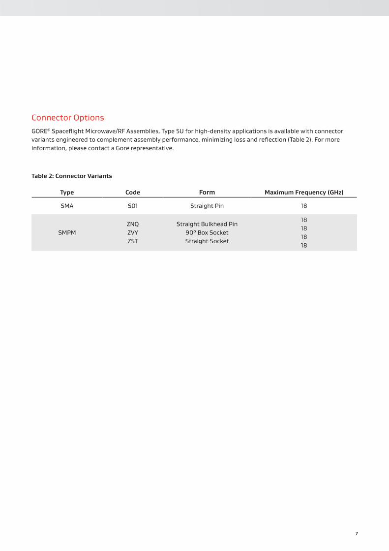
Connector OptionsGORE® Spaceflight Microwave/RF Assemblies, Type 5U for high-density applications is available with connector variants engineered to complement assembly performance, minimizing loss and reflection (Table 2). For more information, please contact a Gore representative.
Table 2: Connector Variants
Type Code Form Maximum Frequency (GHz)
SMA S01 Straight Pin 18
SMPMZNQZVYZST
Straight Bulkhead Pin90° Box SocketStraight Socket
18181818

8
Table 3: Cable Assembly Properties
ElectricalProperty Value
Maximum Frequency (GHz) 32
Standard Impedance (Ohms) 50 ± 1
Insertion Loss dB/m (ft) 1 GHz 18 GHz
0.63 (0.19)2.83 (0.89)
Our coaxial cable assembly delivers stable signals at frequencies ranging from DC to 32 GHz (Table 3). The design of this cable assembly is small, low mass and flexible making it ideal for high-density applications. Type 8S is also available with an SMA connector up to 22 GHz that is qualified according to ESCC-3408 and on the ESA Qualified Parts List (QPL).
Program Heritage
▪ Amos 4 ▪ Galileo IOV ▪ MSG ▪ SBIRS ▪ Sentinel 1
Typical Applications
▪ General payload ▪ High-density interconnects ▪ Inside-the-box connections ▪ Low-mass payload ▪ Multiplexor ▪ Quick connect
Type 8S (2.2 mm / 0.085)
Mechanical / EnvironmentalProperty Value
Jacket Material Tefzel® ETFE
Braided Shield Silver-Plated Copper
Conductor Outer Center
Helically Wrapped Foil/Silver-Plated Copper
Solid / Silver-Plated Copper
Dielectric Material Gore ePTFE
Overall Diameter mm (in) 2.2 (0.085)
Mass g/m (g/ft) 13.1 (4.0)
Minimum Bend Radius mm (in) Single Multiple
6.4 (0.25)12.7 (0.50)
Radiation Resistance (MRad) 700
Operating Temperature Range (⁰C) Standard Qualified
-55 to +150-110 to +150
GORE® Spaceflight Microwave/RF AssembliesFor Traditional Space Applications

9
Connector OptionsGORE® Spaceflight Microwave/RF Assemblies, Type 8S for high-density applications is available with connector variants engineered to complement assembly performance, minimizing loss and reflection (Table 4). For more information, please contact a Gore representative.
Table 4: Connector Variants
Type Code Form Maximum Frequency (GHz)
SMA
S01 S71 ZF8 Y04 S02 R42 S52
Straight Pin90° Box Pin
90° Swept Pin90° Clip Pin
Straight SocketBulkhead Socket
Flange Socket
22 22 22 22 22 22 22
SSMA301371
Straight Pin90° Box Pin
1818
SMP
ZEMZF6ZWCZWKZKRZT4ZS5
Straight Socket90° Box Socket
90° Truncated Box Pin Interface90° Box Socket
90° Extended Box SocketBulkhead PinBulkhead Pin
18 18 18 18 18 18 18
SMPMZVYZST
90° Box SocketStraight Socket
18 18
2.92 mmZMQZQA
Straight Pin90° Box Pin
3232
MCX ZK2 Straight Pin 18
MSSS ZNF Straight Pin 20.5

10
Table 5: Cable Assembly Properties
ElectricalProperty Value
Maximum Frequency (GHz) 22
Insertion Loss dB/m (ft) 1 GHz 18 GHz
0.52 (0.16)2.33 (0.71)
For applications requiring less than 100 flexes, Type 26 is the perfect solution. This flexible coaxial cable assembly ensures reliable signal integrity with excellent phase stability at frequencies ranging from DC to 22 GHz in a small, low-mass footprint (Table 5).
Program Heritage
▪ COSMO ▪ KOMPSAT
Typical Applications
▪ Box-to-box connections ▪ Limited flex applications ▪ Low-mass payload
Type 26 (3.0 mm / 0.120 in)
Mechanical / EnvironmentalProperty Value
Jacket Material Tefzel® ETFE
Braided Shield Silver-Plated Copper
Conductor Outer Center
Helically Wrapped Foil/Silver-Plated Copper
Stranded / Silver-Plated Copper
Dielectric Material Gore ePTFE
Overall Diameter mm (in) 3.0 (0.120)
Mass g/m (g/ft) 29.5 (9.0)
Minimum Bend Radius mm (in) Single Multiple
6.4 (0.25)12.7 (0.50)
Radiation Resistance (MRad) 100
Operating Temperature Range (⁰C) Standard/Qualified -55 to +150
GORE® Spaceflight Microwave/RF AssembliesFor Traditional Space Applications

11
Connector OptionsGORE® Spaceflight Microwave/RF Assemblies, Type 26 for limited flex applications is available with connector variants engineered to complement assembly performance, minimizing loss and reflection (Table 6). For more information, please contact a Gore representative.
Table 6: Connector Variants
Type Code Form Maximum Frequency (GHz)
SMA
S01 S71 ZF8 Y04 S02 R42
Straight Pin90° Box Pin
90° Swept Pin90° Clip Pin
Straight SocketBulkhead Socket
22 22 22 22 22 22
SSMA ZBW 90° Clip Pin 18
SMPZEMZF6ZT3
Straight Socket90° Box Socket
Limited Detent Bulkhead Pin
18 18 18

12
Table 7: Cable Assembly Properties
ElectricalProperty Value
Maximum Frequency (GHz) 32
Insertion Loss dB/m (ft) 1 GHz 18 GHz
0.47 (0.14)2.08 (0.64)
Our coaxial cable assembly transmits optimal signals with improved insertion loss at frequencies ranging from DC to 32 GHz (Table 7). Type 27 offers a low-mass, flexible format that is well-suited for high-density applications such as inside-the-box and box-to-box connections.
Program Heritage
▪ Amos 2 ▪ Intelsat 35 ▪ Quasi-Zenith ▪ ViaSat
Typical Applications
▪ Box-to-box connections ▪ General payload ▪ High-density interconnects ▪ Inside-the-box connections ▪ Low-mass payload ▪ Multiplexer ▪ Quick connect
Type 27 (3.0 mm / 0.120 in Diameter)
Mechanical / EnvironmentalProperty Value
Jacket Material Tefzel® ETFE
Braided Shield Silver-Plated Copper
Conductor Outer Center
Helically Wrapped Foil/Silver-Plated Copper
Solid / Silver-Plated Copper
Dielectric Material Gore ePTFE
Overall Diameter mm (in) 3.0 (0.120)
Mass g/m (g/ft) 29.5 (9.0)
Minimum Bend Radius mm (in) Single Multiple
6.4 (0.25)12.7 (0.50)
Radiation Resistance (MRad) 100
Operating Temperature Range (⁰C) Standard Qualified
-55 to +150-110 to +150
GORE® Spaceflight Microwave/RF AssembliesFor Traditional Space Applications
13
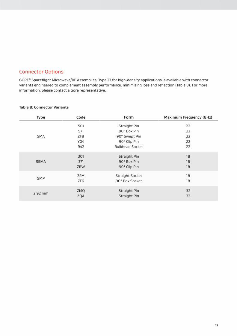
Connector OptionsGORE® Spaceflight Microwave/RF Assemblies, Type 27 for high-density applications is available with connector variants engineered to complement assembly performance, minimizing loss and reflection (Table 8). For more information, please contact a Gore representative.
Table 8: Connector Variants
Type Code Form Maximum Frequency (GHz)
SMA
S01 S71 ZF8 Y04 R42
Straight Pin90° Box Pin
90° Swept Pin90° Clip Pin
Bulkhead Socket
22 22 22 22 22
SSMA301371
ZBW
Straight Pin90° Box Pin90° Clip Pin
18 18 18
SMPZEMZF6
Straight Socket90° Box Socket
18 18
2.92 mmZMQZQA
Straight PinStraight Pin
32 32
14
Table 9: Cable Assembly Properties
ElectricalProperty Value
Maximum Frequency (GHz) 22
Insertion Loss dB/m (ft) 1 GHz 18 GHz
0.59 (0.16)2.33 (0.71)
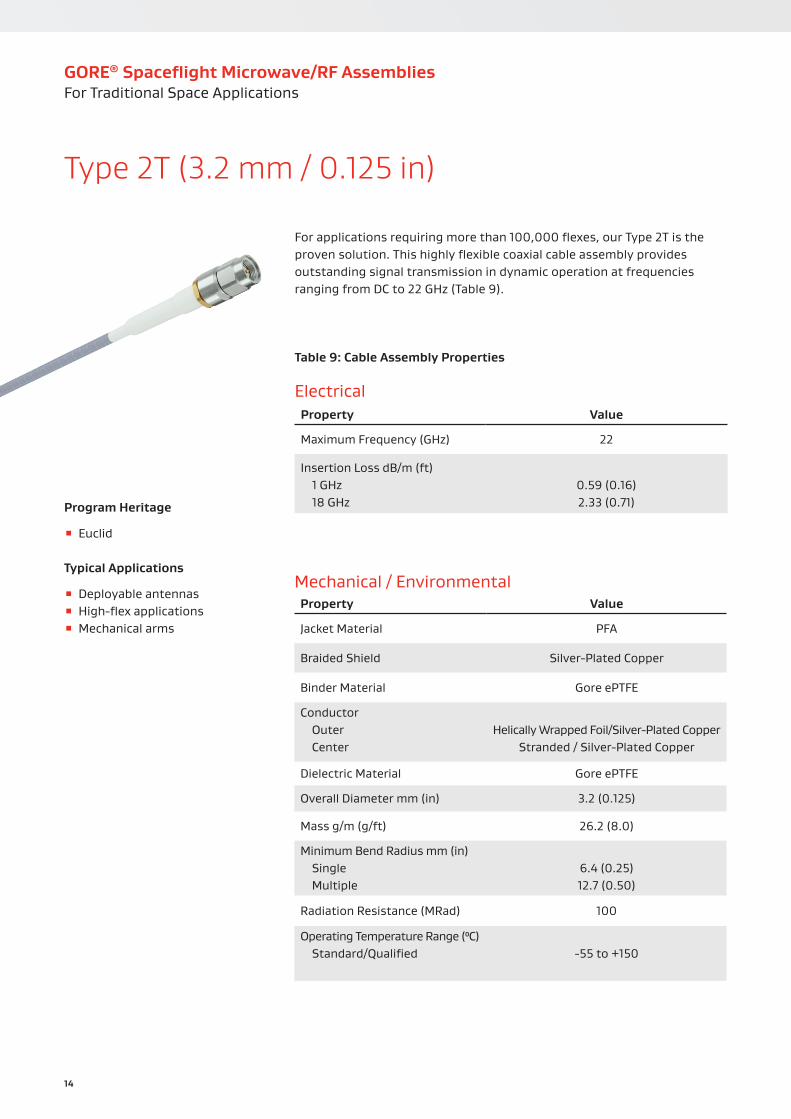
For applications requiring more than 100,000 flexes, our Type 2T is the proven solution. This highly flexible coaxial cable assembly provides outstanding signal transmission in dynamic operation at frequencies ranging from DC to 22 GHz (Table 9).
Program Heritage
▪ Euclid
Typical Applications
▪ Deployable antennas ▪ High-flex applications ▪ Mechanical arms
Type 2T (3.2 mm / 0.125 in)
Mechanical / EnvironmentalProperty Value
Jacket Material PFA
Braided Shield Silver-Plated Copper
Binder Material Gore ePTFE
Conductor Outer Center
Helically Wrapped Foil/Silver-Plated Copper
Stranded / Silver-Plated Copper
Dielectric Material Gore ePTFE
Overall Diameter mm (in) 3.2 (0.125)
Mass g/m (g/ft) 26.2 (8.0)
Minimum Bend Radius mm (in) Single Multiple
6.4 (0.25)12.7 (0.50)
Radiation Resistance (MRad) 100
Operating Temperature Range (⁰C) Standard/Qualified -55 to +150
GORE® Spaceflight Microwave/RF AssembliesFor Traditional Space Applications
15
Connector OptionsGORE® Spaceflight Microwave/RF Assemblies, Type 2T for high-flex applications is available with connector variants engineered to complement assembly performance, minimizing loss and reflection (Table 10). For more information, please contact a Gore representative.
Table 10: Connector Variants
Type Code Form Maximum Frequency (GHz)
2.92 mm ZMQ Straight Pin Vented 22
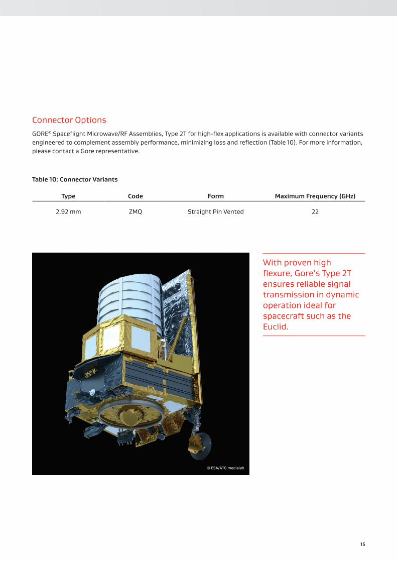
© ESA/ATG medialab
With proven high flexure, Gore’s Type 2T ensures reliable signal transmission in dynamic operation ideal for spacecraft such as the Euclid.

16
Table 11: Cable Assembly Properties
ElectricalProperty Value
Maximum Frequency (GHz) 40
Insertion Loss dB/m (ft) 1 GHz 18 GHz
0.38 (0.11)1.67 (0.52)
Engineered for high-frequency applications, our coaxial cable assembly operates reliably with superior signals ranging from DC to 40 GHz (Table 11). We build Type 56 in a flexible, low-mass package and offer a 2.92 mm connector solution.
Program Heritage
▪ HYLAS ▪ Intelsat 35 ▪ Satmex ▪ SES-15 ▪ TDRS
Typical Applications
▪ Antennas ▪ Box-to-box connections ▪ General payload ▪ High-frequency equipment
Type 56 (3.6 mm / 0.140 in)
Mechanical / EnvironmentalProperty Value
Jacket Material Tefzel® ETFE
Braided Shield Silver-Plated Copper
Conductor Outer Center
Helically Wrapped Foil/Silver-Plated Copper
Solid / Silver-Plated Copper
Dielectric Material Gore ePTFE
Overall Diameter mm (in) 3.6 (0.140)
Mass g/m (g/ft) 36.1 (11.0)
Minimum Bend Radius mm (in) Single Multiple
12.7 (0.50)25.4 (1.0)
Radiation Resistance (MRad) 100
Operating Temperature Range (⁰C) Standard Qualified
-55 to +150 160 to +160
GORE® Spaceflight Microwave/RF AssembliesFor Traditional Space Applications
17
Connector OptionsGORE® Spaceflight Microwave/RF Assemblies, Type 56 for high-frequency applications is available with connector variants engineered to complement assembly performance, minimizing loss and reflection (Table 12). For more information, please contact a Gore representative.
Table 12: Connector Variants
Type Code Form Maximum Frequency (GHz)
2.92 mm
ZMQ ZMR ZMP ZMN
Straight Pin VentedSwept Pin Vented
Straight Socket VentedBulkhead Socket Vented
40 40 40 40
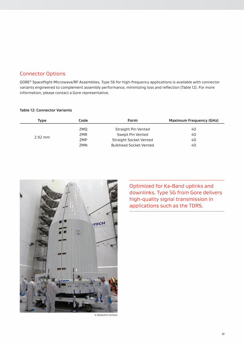
Optimized for Ka-Band uplinks and downlinks, Type 5G from Gore delivers high-quality signal transmission in applications such as the TDRS.
© NASA/Kim Shiflett
18
Table 13: Cable Assembly Properties
ElectricalProperty Value
Maximum Frequency (GHz) 32
Insertion Loss dB/m (ft) 1 GHz 18 GHz
0.26 (0.08)1.14 (0.36)
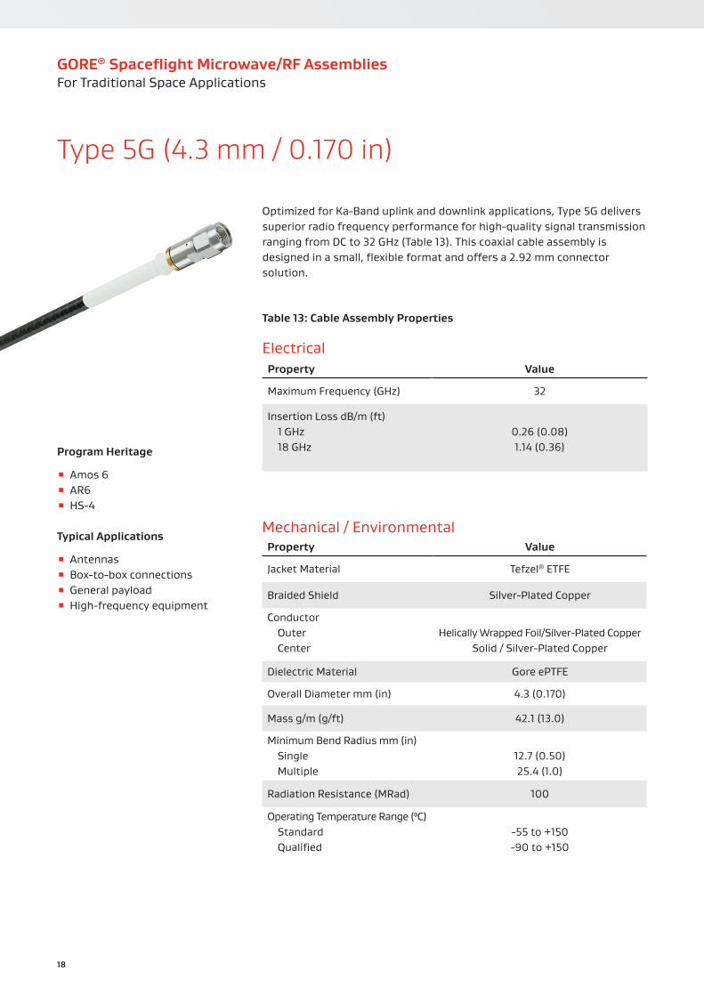
Optimized for Ka-Band uplink and downlink applications, Type 5G delivers superior radio frequency performance for high-quality signal transmission ranging from DC to 32 GHz (Table 13). This coaxial cable assembly is designed in a small, flexible format and offers a 2.92 mm connector solution.
Program Heritage
▪ Amos 6 ▪ AR6 ▪ HS-4
Typical Applications
▪ Antennas ▪ Box-to-box connections ▪ General payload ▪ High-frequency equipment
Type 5G (4.3 mm / 0.170 in)
Mechanical / EnvironmentalProperty Value
Jacket Material Tefzel® ETFE
Braided Shield Silver-Plated Copper
Conductor Outer Center
Helically Wrapped Foil/Silver-Plated Copper
Solid / Silver-Plated Copper
Dielectric Material Gore ePTFE
Overall Diameter mm (in) 4.3 (0.170)
Mass g/m (g/ft) 42.1 (13.0)
Minimum Bend Radius mm (in) Single Multiple
12.7 (0.50)25.4 (1.0)
Radiation Resistance (MRad) 100
Operating Temperature Range (⁰C) Standard Qualified
-55 to +150 -90 to +150
GORE® Spaceflight Microwave/RF AssembliesFor Traditional Space Applications
19
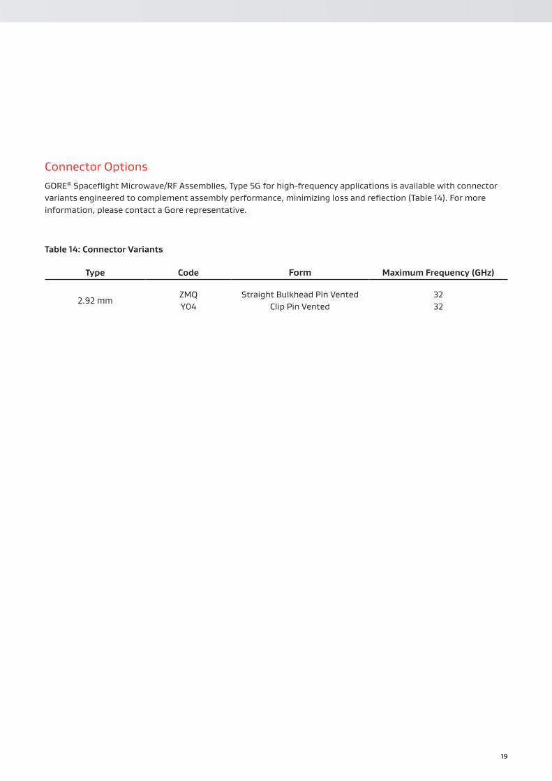
Connector OptionsGORE® Spaceflight Microwave/RF Assemblies, Type 5G for high-frequency applications is available with connector variants engineered to complement assembly performance, minimizing loss and reflection (Table 14). For more information, please contact a Gore representative.
Table 14: Connector Variants
Type Code Form Maximum Frequency (GHz)
2.92 mmZMQ Y04
Straight Bulkhead Pin VentedClip Pin Vented
32 32

20
Table 15: Cable Assembly Properties
ElectricalProperty Value
Maximum Frequency (GHz) 18
Insertion Loss dB/m (ft) 1 GHz 18 GHz
0.31 (0.09)1.39 (0.42)
This flexible coaxial cable assembly is an alternative solution for applications requiring flexing limited to less than 100. Our Type 21 transfers consistently reliable signals with excellent phase stability at frequencies ranging from DC to 18 GHz (Table 15).
Program Heritage
▪ Centaur ▪ CRS ▪ ORB-8 ▪ SES-8
Typical Applications
▪ Box-to-box connections ▪ Limited flex applications ▪ Satellite panel-to-panel equipment
Type 21 (4.8 mm / 0.190 in)
Mechanical / EnvironmentalProperty Value
Jacket Material Tefzel® ETFE
Braided Shield Silver-Plated Copper
Conductor Outer Center
Helically Wrapped Foil/Silver-Plated Copper
Stranded / Silver-Plated Copper
Dielectric Material Gore ePTFE
Overall Diameter mm (in) 4.8 (0.190)
Mass g/m (g/ft) 55.8 (17.0)
Minimum Bend Radius mm (in) Single Multiple
12.7 (0.50)25.4 (1.0)
Radiation Resistance (MRad) 100
Operating Temperature Range (⁰C) Standard/Qualified -55 to +150
GORE® Spaceflight Microwave/RF AssembliesFor Traditional Space Applications

21
Connector OptionsGORE® Spaceflight Microwave/RF Assemblies, Type 21 for high-flex applications is available with connector variants engineered to complement assembly performance, minimizing loss and reflection (Table 16). For more information, please contact a Gore representative.
Table 16: Connector Variants
Type Code Form Maximum Frequency (GHz)
SMAZN1 ZSK ZL7
Straight Pin Vented90⁰ Box Pin Vented
Bulkhead Socket Vented
18 18 18
TNCAZL5 ZSY
Straight Pin Vented Straight Socket Vented
18 18
© ESA/Telerobotics & Haptics Laboratory
Gore’s Type 21 with greater flexibility and consistently reliable signals is an alternative solution for robotic space vehicles requiring limited cable flexing such as the Centaur Rover.
22
Table 17: Cable Assembly Properties
ElectricalProperty Value
Maximum Frequency (GHz) 18
Insertion Loss dB/m (ft) 1 GHz 18 GHz
0.24 (0.07)1.07 (0.34)
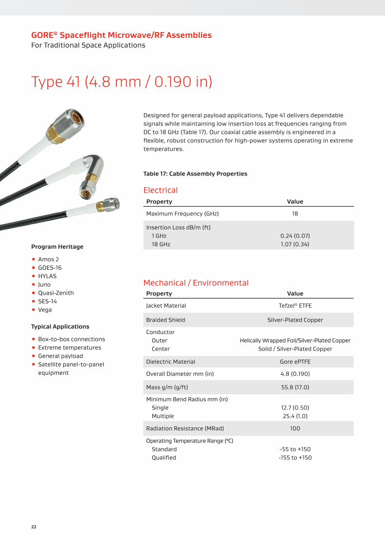
Designed for general payload applications, Type 41 delivers dependable signals while maintaining low insertion loss at frequencies ranging from DC to 18 GHz (Table 17). Our coaxial cable assembly is engineered in a flexible, robust construction for high-power systems operating in extreme temperatures.
Program Heritage
▪ Amos 2 ▪ GOES-16 ▪ HYLAS ▪ Juno ▪ Quasi-Zenith ▪ SES-14 ▪ Vega
Typical Applications
▪ Box-to-box connections ▪ Extreme temperatures ▪ General payload ▪ Satellite panel-to-panel equipment
Type 41 (4.8 mm / 0.190 in)
Mechanical / EnvironmentalProperty Value
Jacket Material Tefzel® ETFE
Braided Shield Silver-Plated Copper
Conductor Outer Center
Helically Wrapped Foil/Silver-Plated Copper
Solid / Silver-Plated Copper
Dielectric Material Gore ePTFE
Overall Diameter mm (in) 4.8 (0.190)
Mass g/m (g/ft) 55.8 (17.0)
Minimum Bend Radius mm (in) Single Multiple
12.7 (0.50)25.4 (1.0)
Radiation Resistance (MRad) 100
Operating Temperature Range (⁰C) Standard Qualified
-55 to +150 -155 to +150
GORE® Spaceflight Microwave/RF AssembliesFor Traditional Space Applications
23
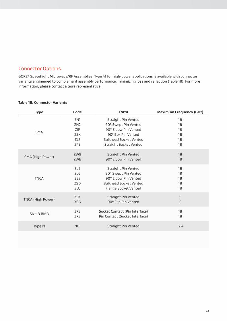
Connector OptionsGORE® Spaceflight Microwave/RF Assemblies, Type 41 for high-power applications is available with connector variants engineered to complement assembly performance, minimizing loss and reflection (Table 18). For more information, please contact a Gore representative.
Table 18: Connector Variants
Type Code Form Maximum Frequency (GHz)
SMA
ZN1 ZN2 ZJP ZSK ZL7 ZP5
Straight Pin Vented90° Swept Pin Vented90° Elbow Pin Vented
90⁰ Box Pin VentedBulkhead Socket VentedStraight Socket Vented
18 18 18 18 18 18
SMA (High Power)ZW9 ZWB
Straight Pin Vented 90° Elbow Pin Vented
18 18
TNCA
ZL5 ZL6 ZS2 ZSD ZLU
Straight Pin Vented90° Swept Pin Vented90° Elbow Pin Vented
Bulkhead Socket VentedFlange Socket Vented
18 18 18 18 18
TNCA (High Power)ZLK Y06
Straight Pin Vented90° Clip Pin Vented
5 5
Size 8 BMBZR2 ZR3
Socket Contact (Pin Interface)Pin Contact (Socket Interface)
18 18
Type N N01 Straight Pin Vented 12.4

24
Table 19: Cable Assembly Properties
ElectricalProperty Value
Maximum Frequency (GHz) 29.5
Insertion Loss dB/m (ft) 1 GHz 18 GHz
0.24 (0.07)1.07 (0.34)
Our coaxial cable assembly with a 2.92 mm connector solution sends high-frequency signals ranging from DC to 29.5 GHz while maintaining low insertion loss (Table 19). Built with durability and flexibility, Type 5D is ideal for general payload applications operating in wide temperatures.
Program Heritage
▪ AMU-1 ▪ DirecTV 15 ▪ HYLAS ▪ SES-14 ▪ ViaSat
Typical Applications
▪ General payload ▪ High-frequency equipment ▪ Satellite panel-to-panel equipment
Type 5D (4.8 mm / 0.190 in)
Mechanical / EnvironmentalProperty Value
Jacket Material Tefzel® ETFE
Braided Shield Silver-Plated Copper
Conductor Outer Center
Helically Wrapped Foil/Silver-Plated Copper
Solid / Silver-Plated Copper
Dielectric Material Gore ePTFE
Overall Diameter mm (in) 4.8 (0.190)
Mass g/m (g/ft) 55.8 (17.0)
Minimum Bend Radius mm (in) Single Multiple
12.7 (0.50)25.4 (1.0)
Radiation Resistance (MRad) 100
Operating Temperature Range (⁰C) Standard Qualified
-55 to +150 -155 to +150
GORE® Spaceflight Microwave/RF AssembliesFor Traditional Space Applications

25
Connector OptionsGORE® Spaceflight Microwave/RF Assemblies, Type 5D for high-frequency applications is available with connector variants engineered to complement assembly performance, minimizing loss and reflection (Table 20). For more information, please contact a Gore representative.
Table 20: Connector Variants
Type Code Form Maximum Frequency (GHz)
2.92 mm
ZUF ZXL ZMQ ZMR ZMP
Straight Pin Vented90° Clip Pin VentedStraight Pin Vented
90° Swept Pin VentedStraight Socket Vented
29.5 29.5 29.5 29.5 29.5
Durable, flexible Type 5D from Gore enables high-frequency signal transmission with low loss in applications such as panel-to-panel equipment in the HYLAS satellite.
© NASA-Bill Stafford
© EADS Astrium

26
Table 21: Cable Assembly Properties
ElectricalProperty Value
Maximum Frequency (GHz) 18
Insertion Loss dB/m (ft) 1 GHz 18 GHz
0.16 (0.05)0.69 (0.22)
With low insertion loss, Type 42 transmits accurate signals at frequencies ranging from DC to 18 GHz (Table 21). Our flexible coaxial cable assembly is ideally suited for applications operating in extreme temperatures such as antennas, high power, and general payload.
Program Heritage
▪ Amos 2 ▪ Atlantic Bird 7 ▪ COSMO ▪ Galileo IOV ▪ GOES-16 ▪ SES-14
Typical Applications
▪ Antennas ▪ Extreme temperatures ▪ General payload ▪ High-power/low PIM/multipaction applications
▪ Satellite panel-to-panel equipment
Type 42 (7.4 mm / 0.290 in)
Mechanical / EnvironmentalProperty Value
Jacket Material Tefzel® ETFE
Braided Shield Silver-Plated Copper
Conductor Outer Center
Helically Wrapped Foil/Silver-Plated Copper
Solid / Silver-Plated Copper
Dielectric Material Gore ePTFE
Overall Diameter mm (in) 7.4 (0.290)
Mass g/m (g/ft) 131.2 (40.0)
Minimum Bend Radius mm (in) Single Multiple
19.0 (0.75)39.1 (1.5)
Radiation Resistance (MRad) 100
Operating Temperature Range (⁰C) Standard Qualified
-55 to +150 -155 to +150
GORE® Spaceflight Microwave/RF AssembliesFor Traditional Space Applications
27
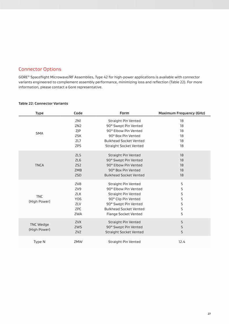
Connector OptionsGORE® Spaceflight Microwave/RF Assemblies, Type 42 for high-power applications is available with connector variants engineered to complement assembly performance, minimizing loss and reflection (Table 22). For more information, please contact a Gore representative.
Table 22: Connector Variants
Type Code Form Maximum Frequency (GHz)
SMA
ZN1 ZN2 ZJP ZSK ZL7 ZP5
Straight Pin Vented90° Swept Pin Vented90° Elbow Pin Vented
90⁰ Box Pin VentedBulkhead Socket VentedStraight Socket Vented
18 18 18 18 18 18
TNCA
ZL5 ZL6 ZS2 ZMB ZSD
Straight Pin Vented 90° Swept Pin Vented 90° Elbow Pin Vented
90° Box Pin Vented Bulkhead Socket Vented
18 18 18 18 18
TNC (High Power)
ZV8 ZV9 ZLK Y06 ZLV ZPC ZWA
Straight Pin Vented90° Elbow Pin Vented
Straight Pin Vented90° Clip Pin Vented
90° Swept Pin VentedBulkhead Socket Vented
Flange Socket Vented
5 5 5 5 5 5 5
TNC Wedge (High Power)
ZVX ZWS ZVZ
Straight Pin Vented90° Swept Pin Vented
Straight Socket Vented
5 5 5
Type N ZMW Straight Pin Vented 12.4

28
Table 23: Cable Assembly Properties
ElectricalProperty Value
Maximum Frequency (GHz) 18
Insertion Loss dB/m (ft) 1 GHz 18 GHz
0.15 (0.04)0.64 (0.02
Our coaxial cable assembly maintains exceptional signal quality and low insertion loss at frequencies ranging from DC to 18 GHz (Table 23). With a flexible format, Type 28 operates reliably and consistently in high-power and antenna applications.
Program Heritage
▪ Alphasat ▪ Astra 5B ▪ Express AM7 ▪ Globalstar 2 ▪ SES-15 ▪ TDRS
Typical Applications
▪ Antennas ▪ Extreme temperatures ▪ High-power/low PIM/multipaction applications
Type 28 (8.1 mm / 0.320 in)
Mechanical / EnvironmentalProperty Value
Jacket Material Tefzel® ETFE
Braided Shield Silver-Plated Copper
Conductor Outer Center
Helically Wrapped Foil/Silver-Plated Copper
Solid / Silver-Plated Copper
Dielectric Material Gore ePTFE
Overall Diameter mm (in) 8.1 (0.320)
Mass g/m (g/ft) 144.3 (44.0)
Minimum Bend Radius mm (in) Single Multiple
25.4 (1.0)50.8 (2.0)
Radiation Resistance (MRad) 100
Operating Temperature Range (⁰C) Standard Qualified
-55 to +150 -155 to +150
GORE® Spaceflight Microwave/RF AssembliesFor Traditional Space Applications

29
Connector OptionsGORE® Spaceflight Microwave/RF Assemblies, Type 28 for high-power applications is available with connector variants engineered to complement assembly performance, minimizing loss and reflection (Table 24). For more information, please contact a Gore representative.
Table 24: Connector Variants
Type Code Form Maximum Frequency (GHz)
SMAZN1 ZSK
Straight Pin Vented90° Box Pin Vented
18 18
TNCAZL5 ZSY ZSD
Straight Pin Vented Straight Socket Vented
Bulkhead Socket Vented
18 18 18
TNC (High Power)
ZLK Y06 ZLW ZPC
Straight Pin Vented90° Clip Pin Vented90° Box Pin Vented
Bulkhead Socket Vented
5 5 5 5
TNC Wedge (High Power)
ZVX ZVZ
Straight Pin VentedStraight Socket Vented
5 5
Type N ZMW Straight Pin Vented 12.4
30
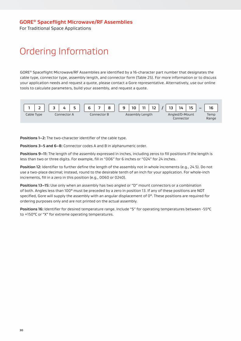
Positions 1–2: The two-character identifier of the cable type.
Positions 3–5 and 6–8: Connector codes A and B in alphanumeric order.
Positions 9–11: The length of the assembly expressed in inches, including zeros to fill positions if the length is less than two or three digits. For example, fill in “006” for 6 inches or “024” for 24 inches.
Position 12: Identifier to further define the length of the assembly not in whole increments (e.g., 24.5). Do not use a two-place decimal; instead, round to the desirable tenth of an inch for your application. For whole-inch increments, fill in a zero in this position (e.g., 0060 or 0240).
Positions 13–15: Use only when an assembly has two angled or “D” mount connectors or a combination of both. Angles less than 100° must be preceded by a zero in position 13. If any of these positions are NOT specified, Gore will supply the assembly with an angular displacement of 0°. These positions are required for ordering purposes only and are not printed on the actual assembly.
Positions 16: Identifier for desired temperature range. Include “S” for operating temperatures between -55°C to +150°C or “X” for extreme operating temperatures.
1 2 3 4 5 6 7 8 9 10 11 12 / 13 14 15 – 16Cable Type Connector A Connector B Assembly Length Angled/D-Mount
ConnectorTemp Range
GORE® Spaceflight Microwave/RF Assemblies are identified by a 16-character part number that designates the cable type, connector type, assembly length, and connector form (Table 25). For more information or to discuss your application needs and request a quote, please contact a Gore representative. Alternatively, use our online tools to calculate parameters, build your assembly, and request a quote.
Ordering Information
GORE® Spaceflight Microwave/RF AssembliesFor Traditional Space Applications
31
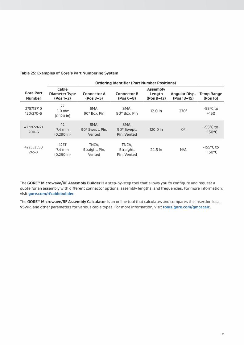
Table 25: Examples of Gore’s Part Numbering System
Ordering Identifier (Part Number Positions)
Gore Part Number
Cable Diameter Type
(Pos 1–2)Connector A
(Pos 3–5)Connector B
(Pos 6–8)
Assembly Length
(Pos 9–12)Angular Disp.
(Pos 13–15)Temp Range
(Pos 16)
27S71S710 120/270-S
27 3.0 mm
(0.120 in)
SMA,90° Box, Pin
SMA,90° Box, Pin
12.0 in 270°-55°C to
+150
42ZN2ZN21 200-S
42 7.4 mm
(0.290 in)
SMA, 90° Swept, Pin,
Vented
SMA, 90° Swept, Pin, Vented
120.0 in 0°-55°C to +150°C
42ZL5ZL50 245-X
42ET 7.4 mm
(0.290 in)
TNCA, Straight, Pin,
Vented
TNCA, Straight,
Pin, Vented24.5 in N/A
-155°C to +150°C
The GORE™ Microwave/RF Assembly Builder is a step-by-step tool that allows you to configure and request a quote for an assembly with different connector options, assembly lengths, and frequencies. For more information, visit gore.com/rfcablebuilder.
The GORE™ Microwave/RF Assembly Calculator is an online tool that calculates and compares the insertion loss, VSWR, and other parameters for various cable types. For more information, visit tools.gore.com/gmcacalc.

32
Notes
______________________________________________________________________________________________
______________________________________________________________________________________________
______________________________________________________________________________________________
______________________________________________________________________________________________
______________________________________________________________________________________________
______________________________________________________________________________________________
______________________________________________________________________________________________
______________________________________________________________________________________________
______________________________________________________________________________________________
______________________________________________________________________________________________
______________________________________________________________________________________________
______________________________________________________________________________________________
______________________________________________________________________________________________
______________________________________________________________________________________________
______________________________________________________________________________________________
______________________________________________________________________________________________
______________________________________________________________________________________________
______________________________________________________________________________________________
______________________________________________________________________________________________
GORE® Spaceflight Microwave/RF AssembliesFor Traditional Space Applications

W. L. Gore & Associates (UK) Ltd.Mariner Drive, Dundee Technology Park, Dundee, DD2 1JA, ScotlandT: 44 1382 561511 F: 44 1382 561007gore.com
GM
CA-0
343-
R3-
DAT
-US-
OCT
19
Information in this publication corresponds to W. L. Gore & Associates’ current knowledge on the subject. It is offered solely to provide possible suggestions for user experimentations. It is NOT intended, however, to substitute for any testing the user may need to conduct to determine the suitability of the product for the user’s particular purposes. Due to the unlimited variety of potential applications for the product, the user must BEFORE production use, determine that the product is suitable for the intended application and is compatible with other component materials. The user is solely responsible for determining the proper amount and placement of the product. Information in this publication may be subject to revision as new knowledge and experience become available. W. L. Gore & Associates cannot anticipate all variations in actual end user conditions, and therefore, makes no warranties and assumes no liability in connection with any use of this information. No information in this publication is to be considered as a license to operate under or a recommendation to infringe any patent right.
NOT INTENDED FOR USE in medical device or food contact applications or with radiation sterilization.
TEFZEL a registered trademark of The CHEMOURS COMPANY FC, LLC.
GORE, Together, improving life, and designs are trademarks of W. L. Gore & Associates, Inc. © 2019 W. L. Gore & Associates, Inc.