Prototyping an Ambient Light System - A Case...
10
PROTOTYPING AN AMBIENT LIGHT SYSTEM - A CASE STUDY Henning Zabel and Achim Rettberg University of Paderborn/C-LAB, Germany {henning.zabel, achim.rettberg}@c-lab.de Abstract: This paper describes an indirect room illumination system which is called Am- bient Light System (ALS). By illumination an object or room in a deliberate manner a certain mood or emotion could be evoked. For example by watching a music video on a television (TV) the room illumination can support the spirit of the music song. The realized room lightning is based on LEDs and enables the illumination with a wide range of RGB colors. The use of LEDs enforces special requirements for power supply, cooling and controlling. In our approach the colors depends on a TV video signal. We propose a hardware setup for driving and controlling a set of LED based lights and a software for capturing and analysing video signals to calculate a representative color, that is used as illumination color. 1. THE AMBIENT LIGHT SYSTEM The development of an ambient light for room lightning is an interesting feature for modern devices, like televisions or music players. Ambient light offers to visualize more visual effects of videos or the spirit of a music song. The ambient light system (ALS) is able to grab a video and light a room with power LEDs in the color shown in the video. The calculation of the lightning is based on the majority of pixels shown in the video. This approach is similar to the idea of the Ambilight c (see [2]) developed by Philips for televisions. Ambilight is an ambient lighting feature that projects a soft light onto the wall behind the TV. The user is able choose from different preset colors and white tones, or it can be fully personalized using the custom settings. Furthermore, Ambilight simply allows adjusting the back light color based upon the action on the screen. In contradiction to the Ambilight, we are able to illuminate the entire room with a specific color. Besides this, due to the flexibility of our ALS it is adaptable to other systems.
Transcript of Prototyping an Ambient Light System - A Case...
PROTOTYPING AN AMBIENT LIGHT SYSTEM -A CASE STUDY
Henning Zabel and Achim RettbergUniversity of Paderborn/C-LAB, Germany{henning.zabel, achim.rettberg}@c-lab.de
Abstract: This paper describes an indirect room illumination system which is called Am-bient Light System (ALS). By illumination an object or room in a deliberatemanner a certain mood or emotion could be evoked. For example by watchinga music video on a television (TV) the room illumination can support the spiritof the music song. The realized room lightning is based on LEDs and enablesthe illumination with a wide range of RGB colors. The use of LEDs enforcesspecial requirements for power supply, cooling and controlling. In our approachthe colors depends on a TV video signal. We propose a hardware setup fordriving and controlling a set of LED based lights and a software for capturingand analysing video signals to calculate a representative color, that is used asillumination color.
1. THE AMBIENT LIGHT SYSTEMThe development of an ambient light for room lightning is an interesting
feature for modern devices, like televisions or music players. Ambient lightoffers to visualize more visual effects of videos or the spirit of a music song.The ambient light system (ALS) is able to grab a video and light a room withpower LEDs in the color shown in the video. The calculation of the lightningis based on the majority of pixels shown in the video. This approach is similarto the idea of the Ambilight c© (see [2]) developed by Philips for televisions.Ambilight is an ambient lighting feature that projects a soft light onto the wallbehind the TV. The user is able choose from different preset colors and whitetones, or it can be fully personalized using the custom settings. Furthermore,Ambilight simply allows adjusting the back light color based upon the actionon the screen. In contradiction to the Ambilight, we are able to illuminate theentire room with a specific color. Besides this, due to the flexibility of our ALSit is adaptable to other systems.
2 Henning Zabel and Achim Rettberg
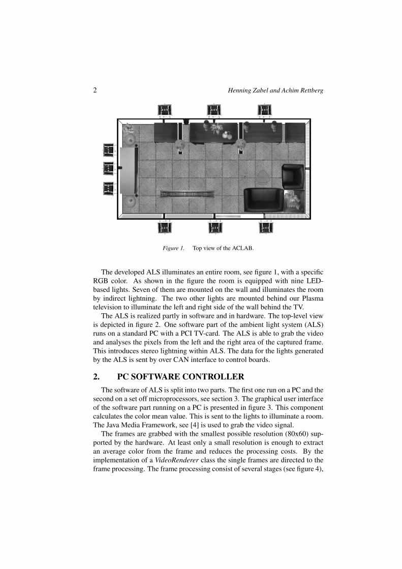
Figure 1. Top view of the ACLAB.
The developed ALS illuminates an entire room, see figure 1, with a specificRGB color. As shown in the figure the room is equipped with nine LED-based lights. Seven of them are mounted on the wall and illuminates the roomby indirect lightning. The two other lights are mounted behind our Plasmatelevision to illuminate the left and right side of the wall behind the TV.
The ALS is realized partly in software and in hardware. The top-level viewis depicted in figure 2. One software part of the ambient light system (ALS)runs on a standard PC with a PCI TV-card. The ALS is able to grab the videoand analyses the pixels from the left and the right area of the captured frame.This introduces stereo lightning within ALS. The data for the lights generatedby the ALS is sent by over CAN interface to control boards.
2. PC SOFTWARE CONTROLLERThe software of ALS is split into two parts. The first one run on a PC and the
second on a set off microprocessors, see section 3. The graphical user interfaceof the software part running on a PC is presented in figure 3. This componentcalculates the color mean value. This is sent to the lights to illuminate a room.The Java Media Framework, see [4] is used to grab the video signal.
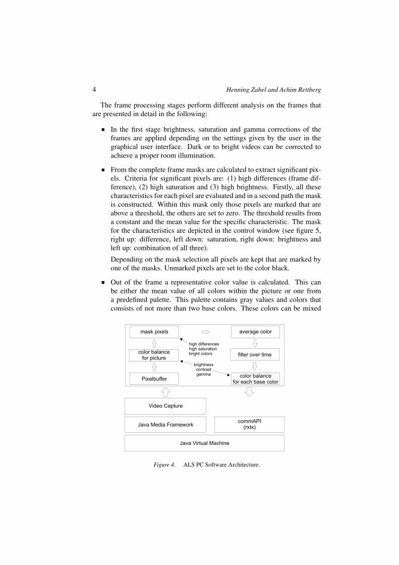
The frames are grabbed with the smallest possible resolution (80x60) sup-ported by the hardware. At least only a small resolution is enough to extractan average color from the frame and reduces the processing costs. By theimplementation of a VideoRenderer class the single frames are directed to theframe processing. The frame processing consist of several stages (see figure 4),

Prototyping an Ambient Light System - a Case Study 3
Figure 2. Ambient Light System (ALS).
Figure 3. Mainwindow of ALS PC Software.
where as each of them can be parameterized by the graphical user interface(see figure 3). The last stage results in an average color value that is transmit-ted via a RS232/CAN interface to the control boards with a communicationAPI (see [1]) for further processing.
4 Henning Zabel and Achim Rettberg
The frame processing stages perform different analysis on the frames thatare presented in detail in the following:
In the first stage brightness, saturation and gamma corrections of theframes are applied depending on the settings given by the user in thegraphical user interface. Dark or to bright videos can be corrected toachieve a proper room illumination.
From the complete frame masks are calculated to extract significant pix-els. Criteria for significant pixels are: (1) high differences (frame dif-ference), (2) high saturation and (3) high brightness. Firstly, all thesecharacteristics for each pixel are evaluated and in a second path the maskis constructed. Within this mask only those pixels are marked that areabove a threshold, the others are set to zero. The threshold results froma constant and the mean value for the specific characteristic. The maskfor the characteristics are depicted in the control window (see figure 5,right up: difference, left down: saturation, right down: brightness andleft up: combination of all three).
Depending on the mask selection all pixels are kept that are marked byone of the masks. Unmarked pixels are set to the color black.
Out of the frame a representative color value is calculated. This canbe either the mean value of all colors within the picture or one froma predefined palette. This palette contains gray values and colors thatconsists of not more than two base colors. These colors can be mixed
Java Virtual Machine
Java Media FrameworkcommAPI
(rxtx)
Video Capture
Pixelbuffer
filter over time
mask pixels average color
color balancefor each base color
color balancefor picture
high differenceshigh saturationbright colors
brightnesscontrastgamma
Figure 4. ALS PC Software Architecture.

Prototyping an Ambient Light System - a Case Study 5
Figure 5. ALS Picture Analysis.
easier as all others. Each pixel of a frame is assigned to one of the palettecolors. The occurrence of each palette color is counted and than the mostcommon color is used as representative. These calculation is performedfor the left and right side of the frame.
During mean value calculation dark areas decrease the brightness of therepresentative color very strong. This reduces the illumination of theroom and with it the effect of the ambient light. Therefore, it is neces-sary that the color has a specific brightness to be involved in the abovementioned calculation. By this, the color black is ignored in general andwith it the above unmarked pixels.
A video card can introduce noise in the captured frames. To filter thisnoise it is possible to calculate a mean value of the representative colorover a specified time period (fading). If the current representative colordiffers from the mean value more than by a user defined value then thisvalue will be taken. In this case the calculation of mean value resets.This allows on the one hand the reduction of noise and jitter that resultsfrom weak color changes and on the other hand direct color switching atscene changes.
To realize a color balance between the calculated representative colorvalue and the real color value that illuminates the room it is necessaryto adjust each base color. This can be done by adjusting the brightness,saturation and most important the gamma value. The calculated colorvalues are transmitted via a serial interface to an RS232/CAN converter.This serial interface is accessed with an implementation of the commu-nication API (see [1]) from SUN.
6 Henning Zabel and Achim Rettberg
3. HARDWARE CONTROLLER BOARDSBesides the software part on a PC, we use a small controller running on a
board (see [3]) with an ATMEL microprocessor AT90CAN128 to control thelights. Each board can handle up to two lights, therefore, to illuminate theroom with nine lights five of these controller boards are needed. These boardsare built in a central control unit. The lights consists of three high-power LEDsmounted on heat sink and a driver board.
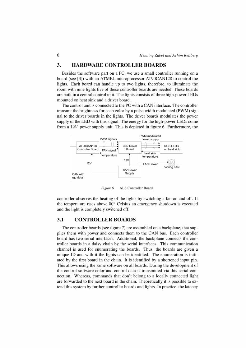
The control unit is connected to the PC with a CAN interface. The controllertransmit the brightness for each color by a pulse width modulated (PWM) sig-nal to the driver boards in the lights. The driver boards modulates the powersupply of the LED with this signal. The energy for the high-power LEDs comefrom a 12V power supply unit. This is depicted in figure 6. Furthermore, the
LED DriverBoard
RGB LED’son heat sink
PWM modulatedpower supply
heat sinktemperature
cooling FANFAN Power
AT90CAN128Controller Board
12V PowerSupply
12V
PWM signals
temperature
FAN signal
CAN withrgb data
12V
Figure 6. ALS Controller Board.
controller observes the heating of the lights by switching a fan on and off. Ifthe temperature rises above 50◦ Celsius an emergency shutdown is executedand the light is completely switched off.
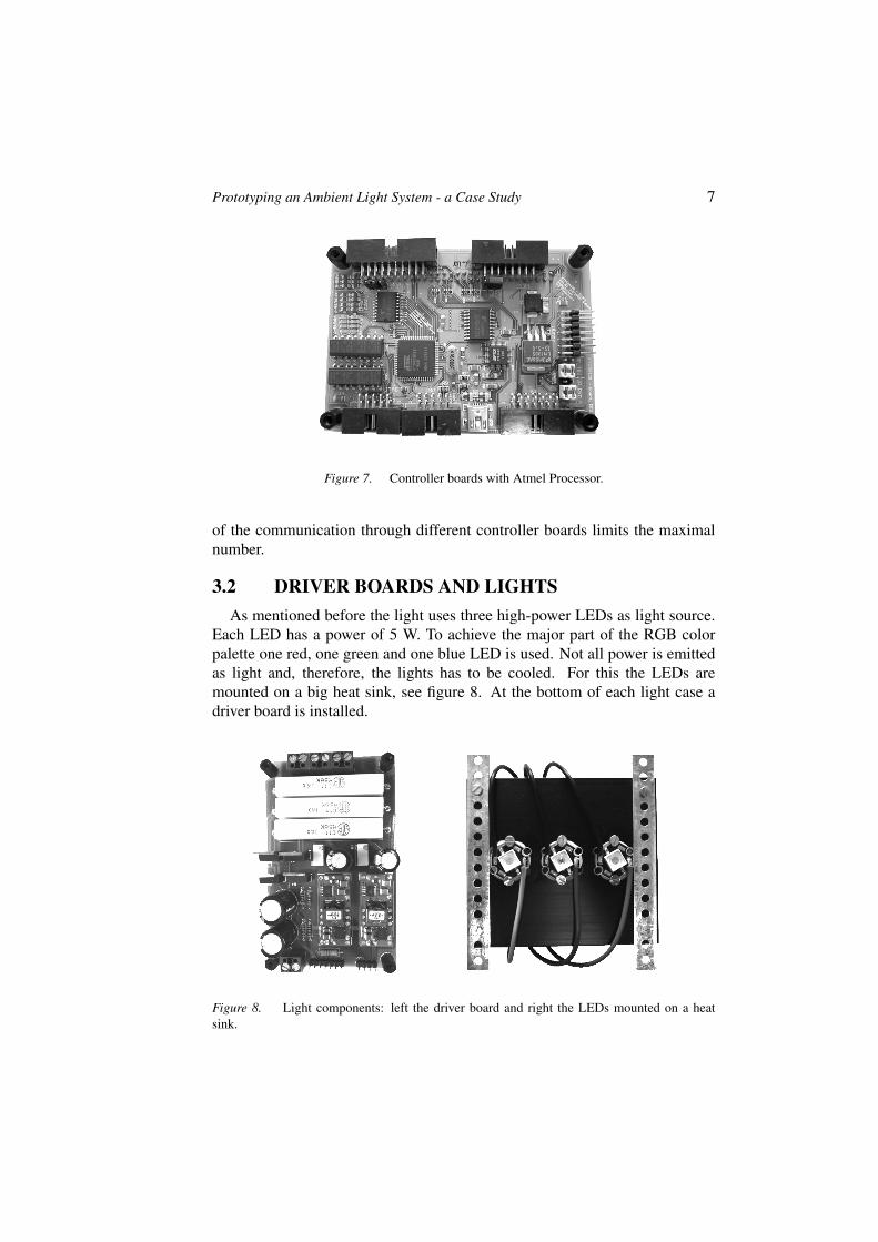
3.1 CONTROLLER BOARDSThe controller boards (see figure 7) are assembled on a backplane, that sup-
plies them with power and connects them to the CAN bus. Each controllerboard has two serial interfaces. Additional, the backplane connects the con-troller boards in a daisy chain by the serial interfaces. This communicationchannel is used for enumerating the boards. Thus, the boards are given aunique ID and with it the lights can be identified. The enumeration is initi-ated by the first board in the chain. It is identified by a shortened input pin.This allows using the same software on all boards. During the development ofthe control software color and control data is transmitted via this serial con-nection. Whereas, commands that don’t belong to a locally connected lightare forwarded to the next board in the chain. Theoretically it is possible to ex-tend this system by further controller boards and lights. In practice, the latency
Prototyping an Ambient Light System - a Case Study 7
Figure 7. Controller boards with Atmel Processor.
of the communication through different controller boards limits the maximalnumber.
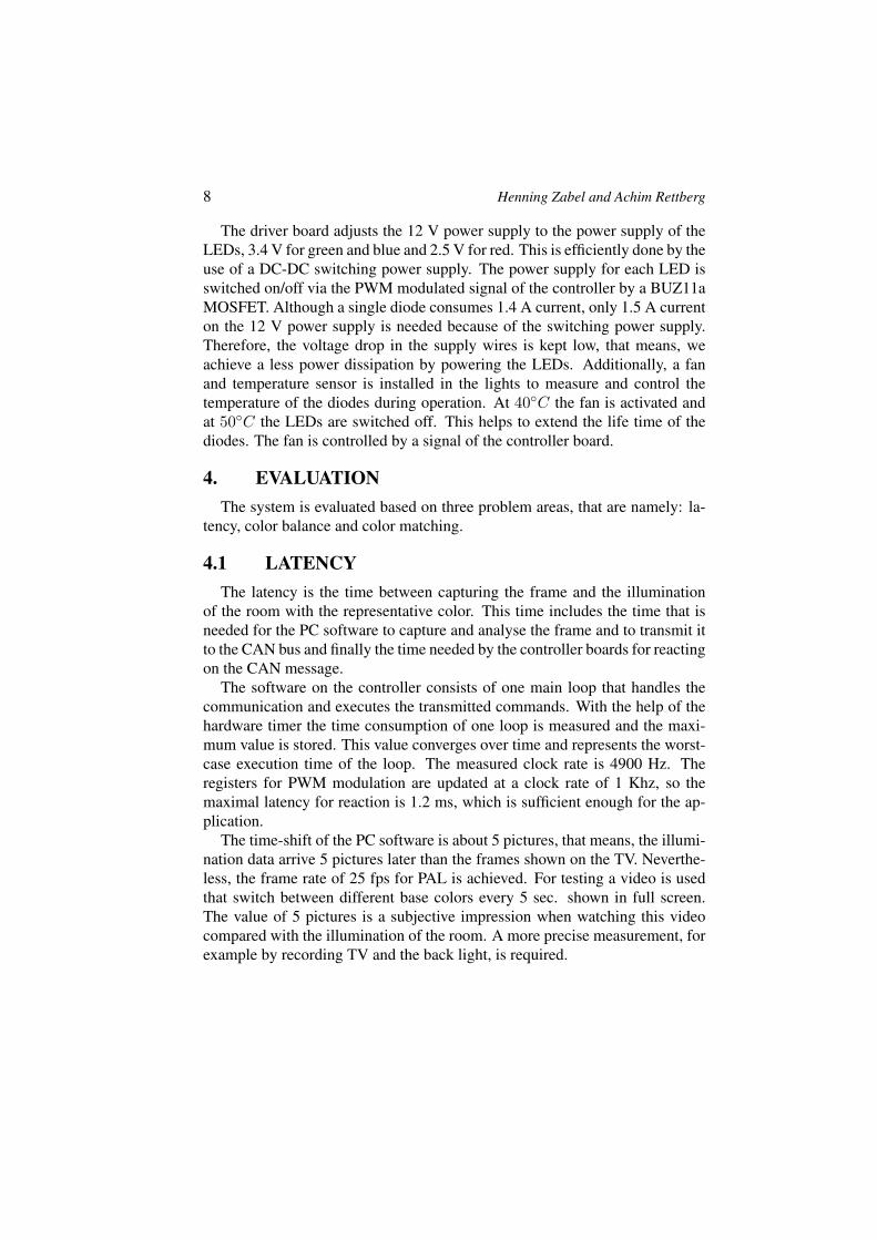
3.2 DRIVER BOARDS AND LIGHTSAs mentioned before the light uses three high-power LEDs as light source.
Each LED has a power of 5 W. To achieve the major part of the RGB colorpalette one red, one green and one blue LED is used. Not all power is emittedas light and, therefore, the lights has to be cooled. For this the LEDs aremounted on a big heat sink, see figure 8. At the bottom of each light case adriver board is installed.
Figure 8. Light components: left the driver board and right the LEDs mounted on a heatsink.
8 Henning Zabel and Achim Rettberg
The driver board adjusts the 12 V power supply to the power supply of theLEDs, 3.4 V for green and blue and 2.5 V for red. This is efficiently done by theuse of a DC-DC switching power supply. The power supply for each LED isswitched on/off via the PWM modulated signal of the controller by a BUZ11aMOSFET. Although a single diode consumes 1.4 A current, only 1.5 A currenton the 12 V power supply is needed because of the switching power supply.Therefore, the voltage drop in the supply wires is kept low, that means, weachieve a less power dissipation by powering the LEDs. Additionally, a fanand temperature sensor is installed in the lights to measure and control thetemperature of the diodes during operation. At 40◦C the fan is activated andat 50◦C the LEDs are switched off. This helps to extend the life time of thediodes. The fan is controlled by a signal of the controller board.
4. EVALUATIONThe system is evaluated based on three problem areas, that are namely: la-
tency, color balance and color matching.
4.1 LATENCYThe latency is the time between capturing the frame and the illumination
of the room with the representative color. This time includes the time that isneeded for the PC software to capture and analyse the frame and to transmit itto the CAN bus and finally the time needed by the controller boards for reactingon the CAN message.
The software on the controller consists of one main loop that handles thecommunication and executes the transmitted commands. With the help of thehardware timer the time consumption of one loop is measured and the maxi-mum value is stored. This value converges over time and represents the worst-case execution time of the loop. The measured clock rate is 4900 Hz. Theregisters for PWM modulation are updated at a clock rate of 1 Khz, so themaximal latency for reaction is 1.2 ms, which is sufficient enough for the ap-plication.
The time-shift of the PC software is about 5 pictures, that means, the illumi-nation data arrive 5 pictures later than the frames shown on the TV. Neverthe-less, the frame rate of 25 fps for PAL is achieved. For testing a video is usedthat switch between different base colors every 5 sec. shown in full screen.The value of 5 pictures is a subjective impression when watching this videocompared with the illumination of the room. A more precise measurement, forexample by recording TV and the back light, is required.
Prototyping an Ambient Light System - a Case Study 9
4.2 COLOR BALANCEThe RGB value of the representative color is represented by three 8 bit val-
ues, one for each color. Also the PWM register on the controller boards have awidth of 8 bit. But in normal the RGB value can not directly be used, becausea color balance has to be applied, similar as it has to be done by crt monitors.For this, it is possible to correct the brightness, saturation and the gamma valuefor each base color. Adjusting the gamma value is most important.
The balance is adjusted manual by comparing different colors on a crt mon-itor with their relating illumination of the room. The easiest way is to startadjusting colors that are a combination of only two base colors. If reducingtheir saturation step by step the color tone should not change until the colorwhite is reached. The colors yellow and orange are problematic, because theyare both a mix ofred and green.
Simply by appliing the gamma correction to each base color, good results incolor representation are achieved. Because each value is only 8bit wide, thiscorrection can be precalculated and stored in arrays. The adjustment duringruntime then simply is an access to this array and avoids further calculations.
4.3 COLOR MATCHINGThe problem of color matching is the question is the representative color
really representative, that means, does it really enhance the impression of thevideo picture. This is very hard to answer, because it heavily depends on thesubjective impression of the viewer and also on the presented video.
When watching life music videos with a stage illumination containing strobelights good results could be achieved by masking the frame with high dif-ference and saturation. When disabling the mean value of the representativecolor over time the stage illumination is transfered in the entire room. In thatcase, the viewer gets the impression of being on stage. During repeating colorswitches that takes less than 5 frames the above mentioned latency leads to aphase shift between the room illumination and the TV. At the worst case theillumination alternates between the TV and the lights. This stresses the eyesextremely.
When watching movies it is more pleasant if averaging the representativecolor over time for about a second. For scenes with less movements (meansless color changes) this reduces flickering of the ambient light and also avoidsnoise produced by the frame grabber card. On the other side, lightnings and fastcolor switches are desired on rapidly changing scenes. For example laser gunshots in science fiction movies should be immediately visible for the audience.Finding an adequate level at which the calculation of the representative colormean value is aborted, is a complicated challenge.
10 Henning Zabel and Achim Rettberg
5. CONCLUSION AND OUTLOOKThis paper presents the ambient light system (ALS). ALS allows the grab-
bing of a video stream and the calculation of the color mean value for lightninga room with power LEDs. The mean value calculation is adaptable by differentmask computations. Therefore, with ALS the user is able to adapt the lightningto his needs. ALS consists of a hardware and software part. For the hardwaretwo boards are developed, the driver board for the low level control of theLEDs and the backplane in the ALS control unit. The software is divided intoa real-time controller and a PC process which analyses the captured frame fromvideo signal to calculate a representative color. On the hardware a maximal la-tency of 1.2 ms is achieved, which is noticeable smaller than the time for oneframe (40 ms). The latency of 5 frames of the PC process is only a subjectivemeasurement. Therefore, the overall latency of our ALS is not precisely de-terminable. Nevertheless, the latency could be measured by recording the TVtogether with the illuminated wall. The difference of the time between the TVshows a single color in full screen and the time point when this color is visibleon the wall is more precise value for this latency. This test should be doneby displaying colors from a small palette to clearly assign the recorded colorsto one of the palette. Additionally, the PC process supports color balance andcolor matching. With our approach of manual adjustment the color balanceachieved sufficient results. The color matching is still an open problem.
As further work, it is planned to replace the PC process step by step withsuitable hardware, like FPGAs for frame processing and when needed addi-tional controller boards. For example calculation of mean value of the repre-sentative color over time and performing of the color balance can be integratedinto the software part running on the controller board.
ACKNOWLEDGMENTSThe following people are involved in the development and assembling pro-
cess and gave some really useful hints and ideas (mentioned in alphabeticalorder): Philip Adelt, Dirk Hopmann, Bernd Kleinjohann, Alexander Krupp,Christoph Löser, Wolfgang Müller, Stefan Rose and Robbie Schäfer.
REFERENCES[1] Keane Jarvi. Communication API for Java: RXTX. http://users.frii.com/
jarvi/rxtx/download.html.
[2] Philips Electronics N.V. Learn about Picture and Sound. http://www.flattv.philips.com/index.cfm?event = main&catid = 1&subcatid = 2&page = pg3.
[3] Paderkicker. ATMEGA128-Board, Rev. 0.2. University of Paderborn/C-LAB, 2005.
[4] Inc. Sun Microsystems. Java Media Framework API (JMF), Version 2.1.1e.http://java.sun.com/products/java-media/jmf/index.jsp, 2006.