
Prototype Design of Fish Feed Pellets Machine based from ...
10
Innovative Systems Design and Engineering www.iiste.org ISSN 2222-1727 (Paper) ISSN 2222-2871 (Online) Vol.7, No.9, 2016 34 Prototype Design of Fish Feed Pellets Machine based from Rice Husk Slamet Riyadi Fakultas Teknik, Universitas Wijaya Putra, Jl. Raya Benowo 1-3 Surabaya 60195 - Indonesia Abstract Prototype Design of fish feed pellets Machine based from Rice Husk, beginning with the planning, design and development of technology. Output planning is an input, it needs to begin concept development stage, the next level of system design and product details. the product development process is the launch of a product testing and improvement of the previous phase. For the design development by identifying opportunities, evaluate and prioritize projects, allocate resources and plan time, completing the preliminary planning of the project, reflecting the results and the process.Stages of Prototype Design of fish feed pellets Machine based from Rice Husk: To identify and study the initial prototype Rice Husk Pellet Machine Manufacturers, which includes: Result Analysis Test Physical Mixture Pellet and Chemical Analysis Feed, Measurement Capacity Pellet Machine Manufacturers Rice Husk.Outcomes Research:, Analysis Prototype Pellet Machine Manufacturers Rice Husk: Effective and efficient in use because there are entrances and exits separate, more efficient because the screw conveyor will be multi-functional, as well as transporting materials rice hulls, screw conveyor will also serve as a stirrer and heat conductor, pipes and cyclone has a low rate for their blower between so it is possible that the maximum powder processes, thermodynamic parameters Static Pressure: 101325.0 Pa, Temperature: 293.2 K, initial solid temperature: 293.2 K, Turbulence parameters Turbulence intensity and length Intensity: 2.00 % Length: 0.015 m, velocity normal to face: 0.5 m/s, thermodynamic parameters Temperature: 293.2 K, Turbulence intensity and length Intensity: 2.00 % Length: 0.015 m. Keywords: prototype design of fish feed pellets machine, rice husk INTRODUCTION Rice husk is always available throughout the year in large enough quantities and are not used as food. Rice husk has the potential to be a feed material because: (1) production is high, (2) use does not compete with human needs, (3) It is not yet widely used for other purposes more economic value so that only waste or burned directly, (4) Its presence is concentrated in certain places (in the rice milling plant) so as to facilitate its collection, (5) continuity guaranteed availability for its main products such as rice. The main obstacle of rice husk as a feed material nutritifnya value is low, characterized by high crude fiber content, protein and low energy. To process the sewage overflow from Rice Husk into pellets in need Pellet Machine Manufacturers. Rice Husk Pellet Machine Manufacturers using the tool electric motor that aims to assist or facilitate the manufacture of pellets economically (Arifuddin, 2014). As The process of making pellet feed by using a machine that has the advantages of its use as follows: Save electricity energy, results of Pellet Good, Maintenance & Repair Easy, Not Easily Broken Use Easy, Automated, attractive design, easy to carry, price, engine capacity, to be overhauled, as shown in the figure below Figure 1: . Figure 1. Rice Husk Pellet Machine Conventional Manufacturers To get rounded the comparison needed a system reducer power and rounded form. With the kind used in fish feed mill in the form of a conveyor, then the rotation used is 150-200 rpm (Brown, 2006). This round was relatively slow rotation. Round slow degradability produced good material and affect the level of dough Hat and solid. Rounded the dough quickly produce crushed and the batter is not out. And the diameter of standard pulleys on additional driving element in diameter and output pulleys reducer too. We can see the two pulleys reducer and diameter input conveyor drive by the formula:
Transcript of Prototype Design of Fish Feed Pellets Machine based from ...

Innovative Systems Design and Engineering www.iiste.org
ISSN 2222-1727 (Paper) ISSN 2222-2871 (Online)
Vol.7, No.9, 2016
34
Prototype Design of Fish Feed Pellets Machine based from Rice
Husk
Slamet Riyadi
Fakultas Teknik, Universitas Wijaya Putra, Jl. Raya Benowo 1-3 Surabaya 60195 - Indonesia
Abstract
Prototype Design of fish feed pellets Machine based from Rice Husk, beginning with the planning, design and
development of technology. Output planning is an input, it needs to begin concept development stage, the next
level of system design and product details. the product development process is the launch of a product testing
and improvement of the previous phase. For the design development by identifying opportunities, evaluate and
prioritize projects, allocate resources and plan time, completing the preliminary planning of the project,
reflecting the results and the process.Stages of Prototype Design of fish feed pellets Machine based from Rice
Husk: To identify and study the initial prototype Rice Husk Pellet Machine Manufacturers, which includes:
Result Analysis Test Physical Mixture Pellet and Chemical Analysis Feed, Measurement Capacity Pellet
Machine Manufacturers Rice Husk.Outcomes Research:, Analysis Prototype Pellet Machine Manufacturers Rice
Husk: Effective and efficient in use because there are entrances and exits separate, more efficient because the
screw conveyor will be multi-functional, as well as transporting materials rice hulls, screw conveyor will also
serve as a stirrer and heat conductor, pipes and cyclone has a low rate for their blower between so it is possible
that the maximum powder processes, thermodynamic parameters Static Pressure: 101325.0 Pa, Temperature:
293.2 K, initial solid temperature: 293.2 K, Turbulence parameters Turbulence intensity and length Intensity:
2.00 % Length: 0.015 m, velocity normal to face: 0.5 m/s, thermodynamic parameters Temperature: 293.2 K,
Turbulence intensity and length Intensity: 2.00 % Length: 0.015 m.
Keywords: prototype design of fish feed pellets machine, rice husk
INTRODUCTION
Rice husk is always available throughout the year in large enough quantities and are not used as food. Rice husk
has the potential to be a feed material because: (1) production is high, (2) use does not compete with human
needs, (3) It is not yet widely used for other purposes more economic value so that only waste or burned directly,
(4) Its presence is concentrated in certain places (in the rice milling plant) so as to facilitate its collection, (5)
continuity guaranteed availability for its main products such as rice. The main obstacle of rice husk as a feed
material nutritifnya value is low, characterized by high crude fiber content, protein and low energy. To process
the sewage overflow from Rice Husk into pellets in need Pellet Machine Manufacturers. Rice Husk Pellet
Machine Manufacturers using the tool electric motor that aims to assist or facilitate the manufacture of pellets
economically (Arifuddin, 2014). As The process of making pellet feed by using a machine that has the
advantages of its use as follows: Save electricity energy, results of Pellet Good, Maintenance & Repair Easy, Not
Easily Broken Use Easy, Automated, attractive design, easy to carry, price, engine capacity, to be overhauled, as
shown in the figure below Figure 1:
.
Figure 1. Rice Husk Pellet Machine Conventional Manufacturers
To get rounded the comparison needed a system reducer power and rounded form. With the kind used
in fish feed mill in the form of a conveyor, then the rotation used is 150-200 rpm (Brown, 2006). This round was
relatively slow rotation. Round slow degradability produced good material and affect the level of dough Hat and
solid. Rounded the dough quickly produce crushed and the batter is not out. And the diameter of standard pulleys
on additional driving element in diameter and output pulleys reducer too. We can see the two pulleys reducer and
diameter input conveyor drive by the formula:

Innovative Systems Design and Engineering www.iiste.org
ISSN 2222-1727 (Paper) ISSN 2222-2871 (Online)
Vol.7, No.9, 2016
35
The parameters are used as reference in motor power is the shaft rotation. The planned rotation axis and diameter
pulleys with a view to maximizing the power contained in the motor without damaging components - the engine
components that have been installed in such a way, so the motor power can be calculated using the equation:
P = Ftot x Vc
Where: P = motor power (W), total Ftot = Force (N), Vc = linear velocity of the shaft (m/s), Ftot = mtot x g, then
power a motor that is used is FtotxW = Vc. Motor power that will be used to drive the chaff processing machine
into pellets (Shigley, 2008)
THEORY
The Design Product Phase
Prototype Design of fish feed pellets Machine based from Rice Husk are generally divided into several phases.
The process begins with a planning phase, associated with the activities of technology development and
advanced research. Output planning phase is the project 's mission statement, which is the input needed to
initiate the concept development phase. Then go on a systems level design phase and product details.
Completion of the product development process is the launch of the product, where the product has been tested
and improved on the previous phase. To develop a product plan and project mission statement, Karl T. Ulrich
and Steven D. Eppinger (2001) proposed a five -stage process is to identify opportunities, evaluate and prioritize
projects, allocate resources and plan time, completing the preliminary planning of the project, reflecting back
results and processes.
Concept Development Phase
In the phase of concept development, Prototype Design of fish feed pellets Machine based from Rice Husk
targets identified market needs, alternative product concepts generated and evaluated, and one or more concepts
selected for further development and experiments. The concept is a description of form, function and appearance
of a product and is usually accompanied by a set of specifications, analysis of competitors' products as well as
economic considerations projects.
System Level Design Phase
System level design phase Prototype Design of fish feed pellets Machine based from Rice Husk include
definition of the product architecture and product descriptions into subsystems and components. Overview final
assembly on the production system is usually defined during this phase. The output of this phase usually includes
the layout of the form of products, functional specifications of each subsystem products, as well as a preliminary
process flow diagram for the final assembly process.
Detail Design Phase Detail design phase Prototype Design of fish feed pellets Machine based from Rice Husk include full
specifications of shapes, materials, and tolerances of all components unique to the product and identification of
all standard components purchased from suppliers. Otherwise the process plan and equipment designed for each
component created in the production system. The output of this phase is the recording control for the product: the
image on the computer file of the shape of each component and equipment production, specifications of
purchased components, as well as plans for the manufacture and assembly process of the product.
Testing and Repair Phase
Prototype testing and refinement phase the design of fish feed pellets Machine based from Rice Husk involves
the construction and evaluation of the various initial production version of the product. An initial prototype
(alpha) are typically made using components with the shape and type of material on actual production, but does
not require the manufacturing process with a process similar to that performed on actual production. Prototype
(alpha) is tested to determine whether the product will work as planned and whether the products meet the needs
of major consumer satisfaction. The next prototype (beta) is usually made with components needed for the
production but not assembled using the final assembly process as the actual assembly. Beta prototype internally
evaluated and tested by consumers to use it directly. The goal of the beta prototype usually is to answer
questions regarding the performance and reliability in order to identify the needs of the changes in techniques for
the final product.
Beginning of the Production Phase
At the beginning of the production phase, Prototype Design of fish feed pellets Machine based from Rice Husk
of products made using actual production system. The purpose of this initial production is to train manpower in

Innovative Systems Design and Engineering www.iiste.org
ISSN 2222-1727 (Paper) ISSN 2222-2871 (Online)
Vol.7, No.9, 2016
36
solving problems that may arise in the actual production process. Products produced during the initial production
sometimes tailored to the customer's wishes and are carefully evaluated to identify deficiencies that arise.
Phase Diagram development of Prototype Design of fish feed pellets Machine
These phases can be described generally as follows Figure 2:
Figure 2. Phase Diagram development of Prototype Design of fish feed pellets Machine based from Rice Husk
To produce a feasibility study conclusions precise and accurate, it is necessary to have the data that is valid and
reliable. The data used to be collected through measures based on the scientific method. The data collected in
this study are primary data and secondary data. According Sekaran and Bougie, 2010: Data can be obtained from
primary and secondary sources. Primary data refers to information obtained first hand the variables necessary for
the specific purpose. Meanwhile, secondary data refers to information from sources that already exists. The
method of collecting data to be used for this research are:
1. Primary Data
a. Direct observation (Observation)
Observation activities will be conducted to get a clear picture before drawing a Prototype Design of fish
feed pellets Machine based from Rice Husk.
b. Structured interview
Structured interview is an interview that dig deeper and add to the information and knowledge about the
object of study Prototype Design of fish feed pellets Machine based from Rice Husk so that the data
obtained will be more complete, accurate and current.
2. Secondary Data
Secondary data is data obtained from various other sources accountable and trustworthy, for example from the
Central Bureau of Statistics, Department of Marine and Fisheries, local, internet websites, papers or studies
sudahpernah made earlier. Secondary data collection aims to increase actuality data have been obtained from the
primary data so that the study of Prototype Design of fish feed pellets Machine based from Rice Husk.
METHODS
Material: Rice husk, Azolla Pinnata, Cassava flour
Tool: SolidWork®
Phase Diagram development of Prototype Design of fish feed pellets Machine based from Rice Husk, see Figure
3
Figure 3. Phase Diagram development of Prototype Design of fish feed pellets Machine
based from Rice Husk (cont.)

Innovative Systems Design and Engineering www.iiste.org
ISSN 2222-1727 (Paper) ISSN 2222-2871 (Online)
Vol.7, No.9, 2016
37
Figure 3. Phase Diagram development of Prototype Design of fish feed pellets Machine
based from Rice Husk
Phase Diagram Information:
1. Identify Phase
Viewing machine rice husk processing into flour determine the formulation of the problem to be achieved.
Conducting a study of various matters relating to the mechanisms and systems in rice husk processing machine
into pellets. In this method intended to obtain feedback on the continuation husk processing machines to be
created so that the machine functions can be made more leverage. To identify and study the corresponding initial
basic information on designing and simulation Prototype Design of fish feed pellets Machine based from Rice
Husk
2. Design Prototype Phase
After undergoing various experimental studies, carried out structural calculations and design drawings for the
process of rice husk processing machine.
a. Making Simulation phase component design. Design drawings and calculations were ripe followed by the
manufacture of the components of the mechanism of rice husk processing machine.
b. Assembly Simulation component design stage. Once all the components are so made the engine components
will be assembled in accordance with the place and function of each - each.
c. Simulation Testing tools phase. All components are installed in this place. Husk processing machines will
be tested using rice husk material. The test covers.
� The process of destruction into flour rice husks
� The formation process of rice husk powder into pellets
3. Product development Prototype
RESULTS AND ANALYSIS
Prototype Design of fish feed pellets Machine based from Rice Husk, there are two design concepts are used as
an alternative and a reference in designing prototype of this machine, namely; Prototype Design of fish feed
pellets Machine based from Rice Husk Without Pipes and Cyclone and Prototype Design of fish feed pellets
Machine based from Rice Husk with Pipe and Cyclone, see Figure 4.
Innovative Systems Design and Engineering www.iiste.org
ISSN 2222-1727 (Paper) ISSN 2222-2871 (Online)
Vol.7, No.9, 2016
38
Figure 4. Prototype Design of fish feed pellets Machine based from Rice Husk
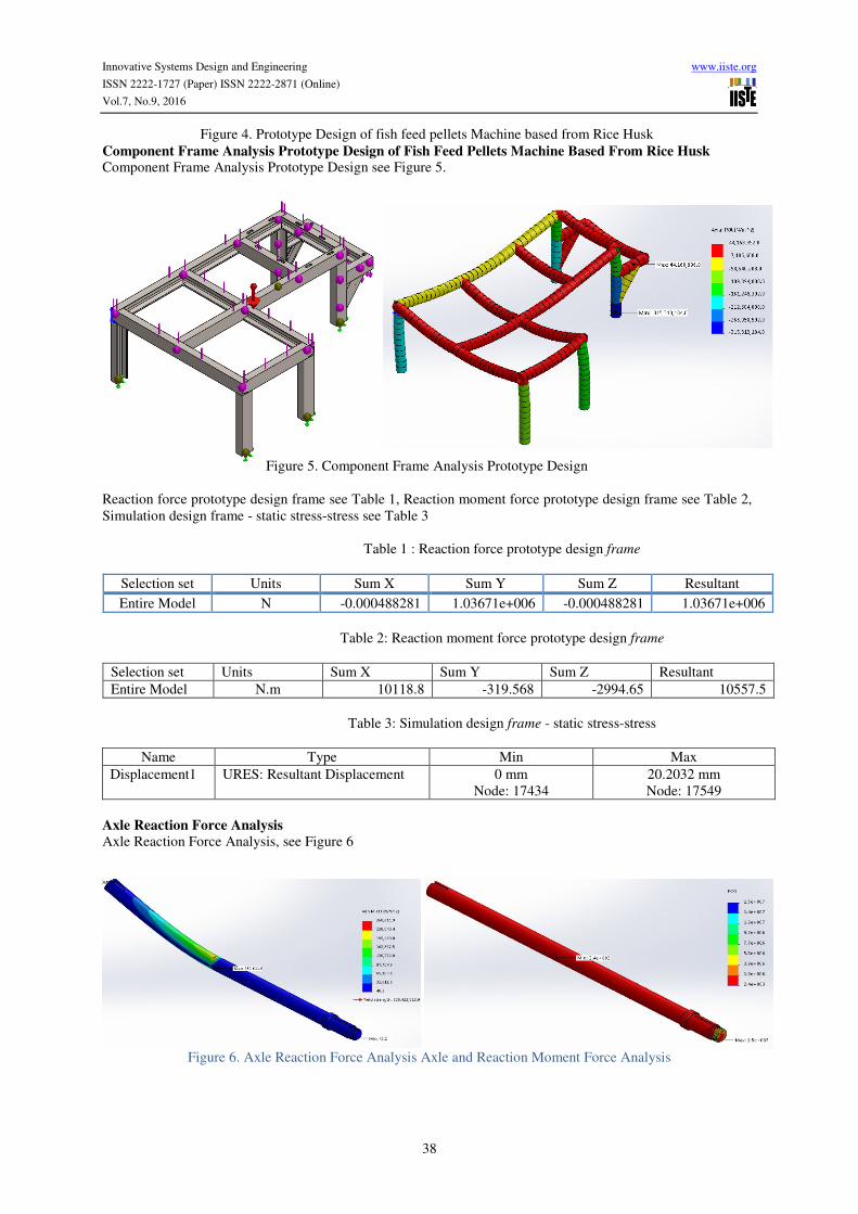
Component Frame Analysis Prototype Design of Fish Feed Pellets Machine Based From Rice Husk Component Frame Analysis Prototype Design see Figure 5.
Figure 5. Component Frame Analysis Prototype Design
Reaction force prototype design frame see Table 1, Reaction moment force prototype design frame see Table 2,
Simulation design frame - static stress-stress see Table 3
Table 1 : Reaction force prototype design frame
Selection set Units Sum X Sum Y Sum Z Resultant
Entire Model N -0.000488281 1.03671e+006 -0.000488281 1.03671e+006
Table 2: Reaction moment force prototype design frame
Selection set Units Sum X Sum Y Sum Z Resultant
Entire Model N.m 10118.8 -319.568 -2994.65 10557.5
Table 3: Simulation design frame - static stress-stress
Name Type Min Max
Displacement1 URES: Resultant Displacement 0 mm
Node: 17434
20.2032 mm
Node: 17549
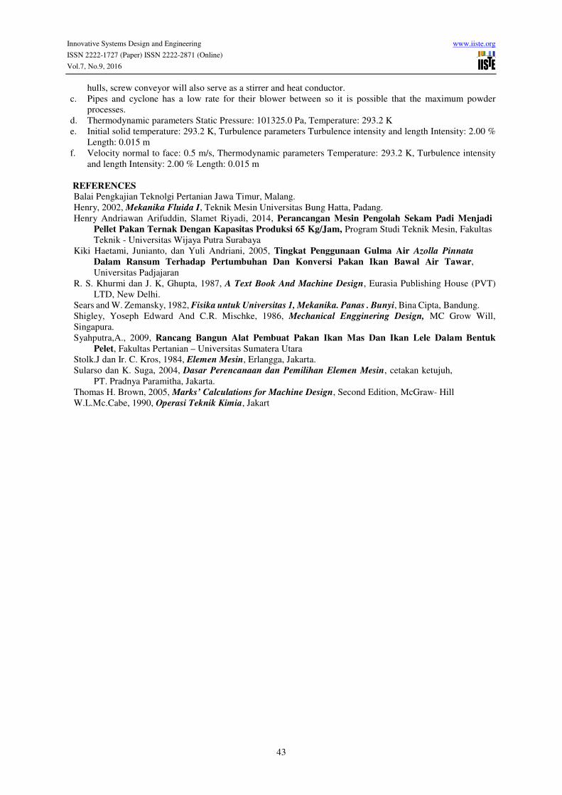
Axle Reaction Force Analysis
Axle Reaction Force Analysis, see Figure 6
Figure 6. Axle Reaction Force Analysis Axle and Reaction Moment Force Analysis

Innovative Systems Design and Engineering www.iiste.org
ISSN 2222-1727 (Paper) ISSN 2222-2871 (Online)
Vol.7, No.9, 2016
39
Axle Reaction Force Analysis Axle see Table 4 and Reaction Moment Force Analysis see Table 5
Table 4: Axle Reaction Force Analysis
Selection set Units Sum X Sum Y Sum Z Resultant
Entire Model N -0.0150707 -6.26986 0.0047828 6.26988
Table 5: Axle Reaction Moment Force Analysis
Selection set Units Sum X Sum Y Sum Z Resultant
Entire Model N.m 0 0 0 0
Results And Analysis Of Fluid Engineering Prototype
Determining configuration The basic steps in the manufacturing flow simulation analysis are as follows:
a. Determine the configuration of which will be used for analysis, either use an existing configuration or new
configuration.
b. Specify the type of analysis to be used for both internal and external. Here also can determine the physical
features.
c. Specifies the default fluid used in this analysis and also the type of flow as laminar, turbulent, or both.
d. Defining the boundary condition for the flow that occurs in the walls of the model geometry.
e. If the project were made does not include heat transfer, we recommend using the "Adiabatic wall". This
type assumes that the walls are insulated completely.
f. If we do not know the degree of fineness of the wall, we should use the default value of "0" (assuming a
smooth wall) Defining density (density) mesh to improve the accuracy of the results obtained.
Computational Domain
Computational domain or wireframe box surrounding the model, defined as a fixed volume with the coordinate
system. Although the fluid in and out of the computational domain computational itself remains fixed. Flow
Simulation to analyze the model and automatically create a computational domain which covers all models, as
shown below Figure 7:
Figure 7. Computational Domain
Cut Process Pressure Plot
Can see the value of maximum pressure and minimum 101098.2 103634.2 Pa Pa look at the color bars are
marked in red to blue for the maximum and minimum. See Figure 8.
Figure 8. Cut Process Pressure Plot
Plot Surface Process Pressure Surface Plot displays results of analysis on the surface of the model. Probe is used to see the value that occurs
diarea we choose. We can see the value of 103634.2 Pa maximum pressure that occur on the surface of the

Innovative Systems Design and Engineering www.iiste.org
ISSN 2222-1727 (Paper) ISSN 2222-2871 (Online)
Vol.7, No.9, 2016
40
hammer mill and minimal body 101098.2 Pa which on the surface look at the color bar outlet marked with red
color to blue color for the maximum and minimum, see Figure 9.
Figure 9. Plot Surface Process Pressure
Pressure Plot Flowtrajectors Process
With Flow trajectories we can see the flow of current and the trajectory of the particles with mass and
temperature that is inserted into the fluid. We can see the value of 103634.2 Pa maximum pressure that occurs in
the body, pressure is happening on the inside of the silo hammer mill with Pa and values 102225.3 101098.2 Pa
minimal value that is on the inside of the outlet channel. Look at the color bars are marked in red to blue for the
maximum and minimum, see Figure 10.
Figure 10. Pressure Plot Flowtrajectors process.
Cut Process Temperature Plot
Temperature can see the value of the maximum and minimum 292.6 293.2 K which look at the color bars are
marked in red to blue for the maximum and minimum see Figure 11.
Figure 11. Cut Process Temperature Plot
Process Temperature Plot FlowTrajectors
Can see the value of the maximum temperature of 293.2 K that occur on the inside of the body, blower and silo
temperature was happening on the inside of the connecting pipe with a minimum value of 292.9 K and 292.6 K

Innovative Systems Design and Engineering www.iiste.org
ISSN 2222-1727 (Paper) ISSN 2222-2871 (Online)
Vol.7, No.9, 2016
41
with the value that the inside of the blower with the vertical direction. Look at the color bars are marked in red to
blue for the maximum and minimum, see Figure 12.
Figure 12. Process Temperature Plot FlowTrajectors
Cut Process Velocity Plot
Can see the value of a maximum speed of 0 m / s and a minimum of 0 m / s which look at the color bars are
marked in red to blue for the maximum and minimum, see Figure 13.
Figure 13. Cut Process Velocity Plot
Plot Surface Velocity process
Velocity can see the value of a maximum of 0:16 m / s in the surface of the hammer mill and minimal blower
0:02 m / s are on the surface of the body look at the color bars are marked in red to blue for the maximum and
minimum, see Figure 14.
Figure 14. Plot Surface Velocity process
Plot FlowTrajectors process Velocity
Can see the value of velocity up to 28.4 m / s happening on the inside of the blower vertical direction, velocity is
happening inside the pipe silo and the outlet pipe to the value 17:10 m / s and a minimum value of 0 m / s are on

Innovative Systems Design and Engineering www.iiste.org
ISSN 2222-1727 (Paper) ISSN 2222-2871 (Online)
Vol.7, No.9, 2016
42
the inside of the body, blower and silo at the color bars are marked in red to blue for the maximum and
minimum, see Figure 15.
Figure 15. Plot FlowTrajectors process Velocity
Process Density Surface Plot
Density can see the value of a maximum of 1:23 kg / m3 in the surface of the hammer mill and minimal body
1:20 kg / m3 at the outlet surface look at the color bars are marked in red to blue for the maximum and
minimum, see Figure 16
Figure 16. Process Density Surface Plot
Plot FlowTrajectors process Density We can see the value of the density maximum of 1:23 kg / m3 occurring on the inside of the body hammer mill
density is happening on the inside of the silo with a value of 1:22 kg / m3 and a minimum value 1:20 kg / m3
which is on the inside of the outlet pipe at the color bar which is marked in red to blue for the maximum and
minimum, see Figure 17.
Figure 17. Plot FlowTrajectors process Density
CONCLUSION
a. Effective and efficient in use because there are entrances and exits separate.
b. More efifien because the screw conveyor will be multi-functional, as well as transporting materials rice
Innovative Systems Design and Engineering www.iiste.org
ISSN 2222-1727 (Paper) ISSN 2222-2871 (Online)
Vol.7, No.9, 2016
43
hulls, screw conveyor will also serve as a stirrer and heat conductor.
c. Pipes and cyclone has a low rate for their blower between so it is possible that the maximum powder
processes.
d. Thermodynamic parameters Static Pressure: 101325.0 Pa, Temperature: 293.2 K
e. Initial solid temperature: 293.2 K, Turbulence parameters Turbulence intensity and length Intensity: 2.00 %
Length: 0.015 m
f. Velocity normal to face: 0.5 m/s, Thermodynamic parameters Temperature: 293.2 K, Turbulence intensity
and length Intensity: 2.00 % Length: 0.015 m
REFERENCES
Balai Pengkajian Teknolgi Pertanian Jawa Timur, Malang.
Henry, 2002, Mekanika Fluida I, Teknik Mesin Universitas Bung Hatta, Padang.
Henry Andriawan Arifuddin, Slamet Riyadi, 2014, Perancangan Mesin Pengolah Sekam Padi Menjadi
Pellet Pakan Ternak Dengan Kapasitas Produksi 65 Kg/Jam, Program Studi Teknik Mesin, Fakultas
Teknik - Universitas Wijaya Putra Surabaya
Kiki Haetami, Junianto, dan Yuli Andriani, 2005, Tingkat Penggunaan Gulma Air Azolla Pinnata
Dalam Ransum Terhadap Pertumbuhan Dan Konversi Pakan Ikan Bawal Air Tawar,
Universitas Padjajaran
R. S. Khurmi dan J. K, Ghupta, 1987, A Text Book And Machine Design, Eurasia Publishing House (PVT)
LTD, New Delhi.
Sears and W. Zemansky, 1982, Fisika untuk Universitas 1, Mekanika. Panas . Bunyi, Bina Cipta, Bandung.
Shigley, Yoseph Edward And C.R. Mischke, 1986, Mechanical Engginering Design, MC Grow Will,
Singapura.
Syahputra,A., 2009, Rancang Bangun Alat Pembuat Pakan Ikan Mas Dan Ikan Lele Dalam Bentuk
Pelet, Fakultas Pertanian – Universitas Sumatera Utara
Stolk.J dan Ir. C. Kros, 1984, Elemen Mesin, Erlangga, Jakarta.
Sularso dan K. Suga, 2004, Dasar Perencanaan dan Pemilihan Elemen Mesin, cetakan ketujuh,
PT. Pradnya Paramitha, Jakarta.
Thomas H. Brown, 2005, Marks’ Calculations for Machine Design, Second Edition, McGraw- Hill
W.L.Mc.Cabe, 1990, Operasi Teknik Kimia, Jakart