ProtoNode FPC-N34 and ProtoNode FPC-N35 Start-up … · (Section 8) ClimateWorx ProtoNode Start-up...
46
Document Revision: 4.A Web Configurator Template Revision: 64 ProtoNode FPC-N34 and ProtoNode FPC-N35 Start-up Guide For Interfacing ClimateWorx Products: M52 Controller To Building Automation Systems: BACnet MS/TP, BACnet/IP, BACnet Ethernet, Modbus TCP/IP, Metasys N2 and LonWorks APPLICABILITY & EFFECTIVITY Explains ProtoNode hardware and how to install it. The instructions are effective for the above as of November 2016.
Transcript of ProtoNode FPC-N34 and ProtoNode FPC-N35 Start-up … · (Section 8) ClimateWorx ProtoNode Start-up...

Document Revision: 4.A Web Configurator
Template Revision: 64
ProtoNode FPC-N34 and ProtoNode FPC-N35 Start-up Guide
For Interfacing ClimateWorx Products: M52 Controller
To Building Automation Systems: BACnet MS/TP, BACnet/IP, BACnet Ethernet, Modbus TCP/IP, Metasys N2 and LonWorks
APPLICABILITY & EFFECTIVITY
Explains ProtoNode hardware and how to install it.
The instructions are effective for the above as of November 2016.

ClimateWorx ProtoNode Start-up Guide
Page 2 of 46
Technical Support
Thank you for purchasing the ProtoNode for ClimateWorx. Please call ClimateWorx for Technical support of the ProtoNode product. Sierra Monitor Corporation does not provide direct support. If ClimateWorx needs to escalate the concern, they will contact Sierra Monitor Corporation for assistance. Support Contact Information:
ClimateWorx 14 Chelsea Lane Brampton, Ontario
Customer Service: (905) 405-0800
Email: [email protected] Website: www.climateworxinternational.com

ClimateWorx ProtoNode Start-up Guide
Page 3 of 46
Quick Start Guide
1. Record the information about the unit. (Section 3.1)
2. Set the device’s COM settings and Node-ID’s for each of the devices that are to connect to
ProtoNode FPC-N34 or FPC-N35. (Section 3.3)
3. ProtoNode FPC-N34 units: Select the Field Protocol on the S Bank Dip Switches. (Section 3.4)
4. BACnet MS/TP (FPC-N34): Set the MAC Address on DIP Switch Bank A. (Section 3.5.1)
5. BACnet MS/TP (FPC-N34): Set the BAUD rate of the BACnet MS/TP Field Protocol on DIP Switch
Bank B. (Section 3.5.2)
6. Connect ProtoNode 6 pin RS-485 connector to the RS-485 network that is connected to each of the
devices. (Section 4.2)
7. Connect ProtoNode FPC-N34’s 3 pin RS-485 port to the Field Protocol cabling, (Section 4.3)
or connect ProtoNode FPC-N35’s 2 pin LonWorks port to the Field Protocol cabling. (Section 4.4)
8. Connect Power to ProtoNode 6 pin connector. (Section 4.5)
9. Use a browser to access the ProtoNode’s embedded tool, which is referred to in this manual as the
Web Configurator, to select the devices that are to attach to the ProtoNode and set the current
Modbus Node-ID for each these products. Once the devices are selected, the ProtoNode
Automatically builds and loads the Configuration for the devices. (Section 5)
10. BACnet/IP or Modbus TCP/IP (FPC-N34): Use a browser to access the ProtoNode Web Configurator
to change the IP Address. No changes to the configuration are necessary. (Section 5.4)
11. LonWorks (FPC-N35): The ProtoNode must be commissioned on the LonWorks Network. This needs
to be done by the LonWorks administrator using a LonWorks Commissioning tool. (Section 8)
ClimateWorx ProtoNode Start-up Guide
Page 4 of 46
TABLE OF CONTENTS
1 Certifications ........................................................................................................................................ 6 1.1 BTL Mark – BACnet
® Testing Laboratory ....................................................................................... 6
1.2 LonMark Certification ...................................................................................................................... 6
2 Introduction .......................................................................................................................................... 7 2.1 ProtoNode Gateway ....................................................................................................................... 7
3 Setup for ProtoNode ............................................................................................................................ 8 3.1 Record Identification Data .............................................................................................................. 8 3.2 Point Count Capacity and Registers per Device ............................................................................ 8 3.3 Configuring Device Communications ............................................................................................. 9
3.3.1 Input COM Settings on all Devices Connected to the ProtoNode ............................................ 9 3.3.2 Set Modbus Node-ID for each Device attached to the ProtoNode ........................................... 9
3.4 Selecting the Desired Field Protocol ............................................................................................ 10 3.5 BMS Network Settings: MAC Address, Device Instance and Baud Rate .................................... 11
3.5.1 BACnet MS/TP (FPC-N34): Setting the MAC Address for BMS Network .............................. 11 3.5.2 BACnet MS/TP (FPC-N34): Setting the Baud Rate for BMS Network .................................... 12
3.5.2.1 Baud Rate DIP Switch Selection ..................................................................................... 12
4 Interfacing ProtoNode to Devices .................................................................................................... 13 4.1 ProtoNode FPC-N34 and FPC-N35 Showing Connection Ports .................................................. 13 4.2 Device Connections to ProtoNode ............................................................................................... 14
4.2.1 Biasing the Modbus RS-485 Device Network ......................................................................... 15 4.2.2 End of Line Termination Switch for the Modbus RS-485 Device Network.............................. 16
4.3 BACnet MS/TP or Metasys N2 (FPC-N34): Wiring Field Port to RS-485 Network ...................... 17 4.4 LonWorks (FPC-N35): Wiring LonWorks Devices to the LonWorks Terminal ............................. 17 4.5 Power-Up ProtoNode.................................................................................................................... 18
5 Use ProtoNode Web Configurator to Setup the Gateway ............................................................. 19 5.1 Connect the PC to ProtoNode via the Ethernet Port .................................................................... 19 5.2 Connecting to ProtoNode Web Configurator ................................................................................ 20 5.3 Selecting Profiles for Devices Connected to ProtoNode .............................................................. 20 5.4 BACnet/IP and Modbus TCP/IP: Setting IP Address for Field Network ....................................... 22
6 BACnet MS/TP and BACnet/IP: Setting Node_Offset to Assign Specific Device Instances ..... 24
7 How to Start the Installation Over: Clearing Profiles ..................................................................... 25
8 LonWorks (FPC-N35): Commissioning ProtoNode on a lonworks Network ............................... 26 8.1 Commissioning ProtoNode FPC-N35 on a LonWorks Network ................................................... 26
8.1.1 Instructions to Download XIF File from ProtoNode FPC-N35 Using Browser ........................ 26
9 BACnet Explorer ................................................................................................................................ 28
Appendix A. Troubleshooting .................................................................................................................. 29 Lost or Incorrect IP Address ............................................................................................ 29 Appendix A.1. Viewing Diagnostic information ........................................................................................ 30 Appendix A.2. Check Wiring and Settings............................................................................................... 31 Appendix A.3. LED Diagnostics for Communications Between ProtoNode and Devices ....................... 32 Appendix A.4. Take Diagnostic Capture with the FieldServer Toolbox .................................................. 33 Appendix A.5. Update Firmware ............................................................................................................. 36 Appendix A.6. BACnet: Setting Network_Number for more than one ProtoNode on Subnet ................. 36 Appendix A.7. Securing ProtoNode with Passwords .............................................................................. 37 Appendix A.8.
Appendix B. Vendor Information - ClimateWorx ................................................................................... 38 M52 Controller Modbus RTU Mappings to BACnet, Metasys N2, Modbus TCP/IP and Appendix B.1.
LonWorks ................................................................................................................................................ 38
Appendix C. “A” Bank DIP Switch Settings ........................................................................................... 42 “A” Bank DIP Switch Settings .......................................................................................... 42 Appendix C.1.
ClimateWorx ProtoNode Start-up Guide
Page 5 of 46
Appendix D. Reference ............................................................................................................................. 45 Specifications ................................................................................................................... 45 Appendix D.1.
Appendix D.1.1. Compliance with UL Regulations ........................................................................... 45
Appendix E. Limited 2 Year Warranty ..................................................................................................... 46
LIST OF FIGURES
Figure 1: ProtoNode Part Numbers .............................................................................................................. 8 Figure 2: Supported Point Count Capacity ................................................................................................... 8 Figure 3: Registers per Device ..................................................................................................................... 8 Figure 4: COM Settings ................................................................................................................................. 9 Figure 5: S Bank DIP Switches ................................................................................................................... 10 Figure 6: MAC Address DIP Switches ........................................................................................................ 11 Figure 7: Baud Rate DIP Switches ............................................................................................................. 12 Figure 8: BMS Baud Rate ........................................................................................................................... 12 Figure 9: ProtoNode FPC-N34 (upper) and ProtoNode FPC-N35 (lower) ................................................. 13 Figure 10: RS-485 and Power Connections ............................................................................................... 14 Figure 11: Modbus RS-485 Biasing Switch on the ProtoNode N34 (left) and ProtoNode N35 (right)........ 15 Figure 12: Modbus RS-485 End-Of-Line Termination Switch on the ProtoNode N34 (left) and ................ 16 Figure 13: Connection from ProtoNode to RS-485 Field Network .............................................................. 17 Figure 14: RS-485 BMS Network EOL Switch ............................................................................................ 17 Figure 15: LonWorks Terminal .................................................................................................................... 17 Figure 16: Required current draw for the ProtoNode .................................................................................. 18 Figure 17: Power Connections .................................................................................................................... 18 Figure 18: Web Configurator Showing no Active Profiles ........................................................................... 20 Figure 19: Web Configurator Showing Active Profile Additions .................................................................. 21 Figure 20: Web Configurator Screen with Active Profiles ........................................................................... 22 Figure 21: Changing IP Address via Web GUI ........................................................................................... 23 Figure 22: Web Configurator Screen .......................................................................................................... 24 Figure 23: LonWorks Service Pin Location ................................................................................................. 26 Figure 24: Sample of Fserver.XIF File Generated ...................................................................................... 27 Figure 25: BACnet Explorer on a BACnet Network .................................................................................... 28 Figure 26: Ethernet Port Location ............................................................................................................... 29 Figure 27: Error Messages Screen ............................................................................................................. 30 Figure 28: Diagnostic LEDs ........................................................................................................................ 32 Figure 29: Ethernet Port Location ............................................................................................................... 33 Figure 30: Web Configurator – Setting Network Number for BACnet......................................................... 36 Figure 31: Specifications ............................................................................................................................. 45
ClimateWorx ProtoNode Start-up Guide
Page 6 of 46
1 CERTIFICATIONS
1.1 BTL Mark – BACnet®1 Testing Laboratory
1.2 LonMark Certif ication
1 BACnet is a registered trademark of ASHRAE
The BTL Mark on ProtoNode is a symbol that indicates that a product has
passed a series of rigorous tests conducted by an independent laboratory
which verifies that the product correctly implements the BACnet features
claimed in the listing. The mark is a symbol of a high-quality BACnet product.
Go to http://www.BACnetInternational.net/btl/ for more information about the BACnet Testing Laboratory. Click here for BACnet PIC Statement.
LonMark International is the recognized authority for certification, education,
and promotion of interoperability standards for the benefit of manufacturers,
integrators and end users. LonMark International has developed extensive
product certification standards and tests to provide the integrator and user with
confidence that products from multiple manufacturers utilizing LonMark
devices work together. Sierra Monitor has more LonMark Certified gateways
than any other gateway manufacturer, including the ProtoCessor, ProtoCarrier
and ProtoNode for OEM applications and the full featured, configurable
gateways.
ClimateWorx ProtoNode Start-up Guide
Page 7 of 46
2 INTRODUCTION
2.1 ProtoNode Gateway
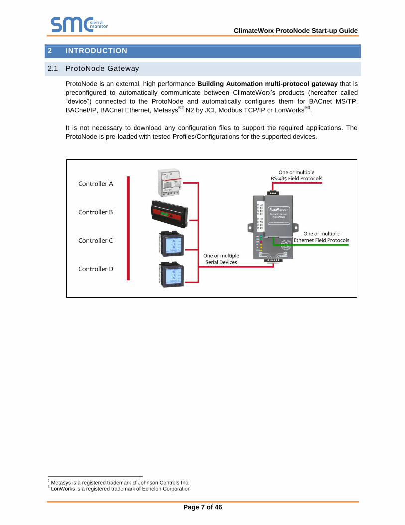
ProtoNode is an external, high performance Building Automation multi-protocol gateway that is
preconfigured to automatically communicate between ClimateWorx’s products (hereafter called
“device”) connected to the ProtoNode and automatically configures them for BACnet MS/TP,
BACnet/IP, BACnet Ethernet, Metasys®2
N2 by JCI, Modbus TCP/IP or LonWorks®3
.
It is not necessary to download any configuration files to support the required applications. The
ProtoNode is pre-loaded with tested Profiles/Configurations for the supported devices.
2 Metasys is a registered trademark of Johnson Controls Inc.
3 LonWorks is a registered trademark of Echelon Corporation
ClimateWorx ProtoNode Start-up Guide
Page 8 of 46
3 SETUP FOR PROTONODE
3.1 Record Identif ication Data
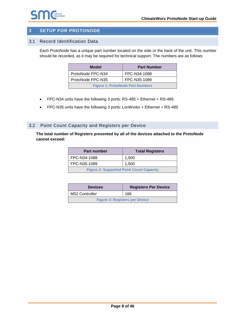
Each ProtoNode has a unique part number located on the side or the back of the unit. This number
should be recorded, as it may be required for technical support. The numbers are as follows:
Model Part Number
ProtoNode FPC-N34 FPC-N34-1088
ProtoNode FPC-N35 FPC-N35-1089
Figure 1: ProtoNode Part Numbers
FPC-N34 units have the following 3 ports: RS-485 + Ethernet + RS-485
FPC-N35 units have the following 3 ports: LonWorks + Ethernet + RS-485
3.2 Point Count Capacity and Registers per Device
The total number of Registers presented by all of the devices attached to the ProtoNode
cannot exceed:
Part number Total Registers
FPC-N34-1088 1,500
FPC-N35-1089 1,500
Figure 2: Supported Point Count Capacity
Devices Registers Per Device
M52 Controller 166
Figure 3: Registers per Device

ClimateWorx ProtoNode Start-up Guide
Page 9 of 46
3.3 Configuring Device Communications
3.3.1 Input COM Settings on all Devices Connected to the ProtoNode
All of the connected serial devices MUST have the same Baud Rate, Data Bits, Stop Bits,
and Parity settings as the ProtoNode.
Figure 4 specifies the device serial port settings required to communicate with the ProtoNode.
Port Setting Device
Protocol Modbus RTU
Baud Rate 9600
Parity None
Data Bits 8
Stop Bits 1
Figure 4: COM Settings
3.3.2 Set Modbus Node-ID for each Device attached to the ProtoNode
Set Modbus Node-ID for each of the devices attached to ProtoNode. The Modbus Node-ID’s
need to be uniquely assigned between 1 and 255.
o The Modbus Node-ID that is assigned for each device needs to be documented
The Modbus Node-ID’s assigned are used for designating the Device Instance
for BACnet/IP and BACnet MS/TP (Section 6)
The Metasys N2 and Modbus TCP/IP field protocol Node-IDs are automatically set to be the
same value as the Node-ID of the Modbus RTU device.
ClimateWorx ProtoNode Start-up Guide
Page 10 of 46
3.4 Selecting the Desired Field Protocol
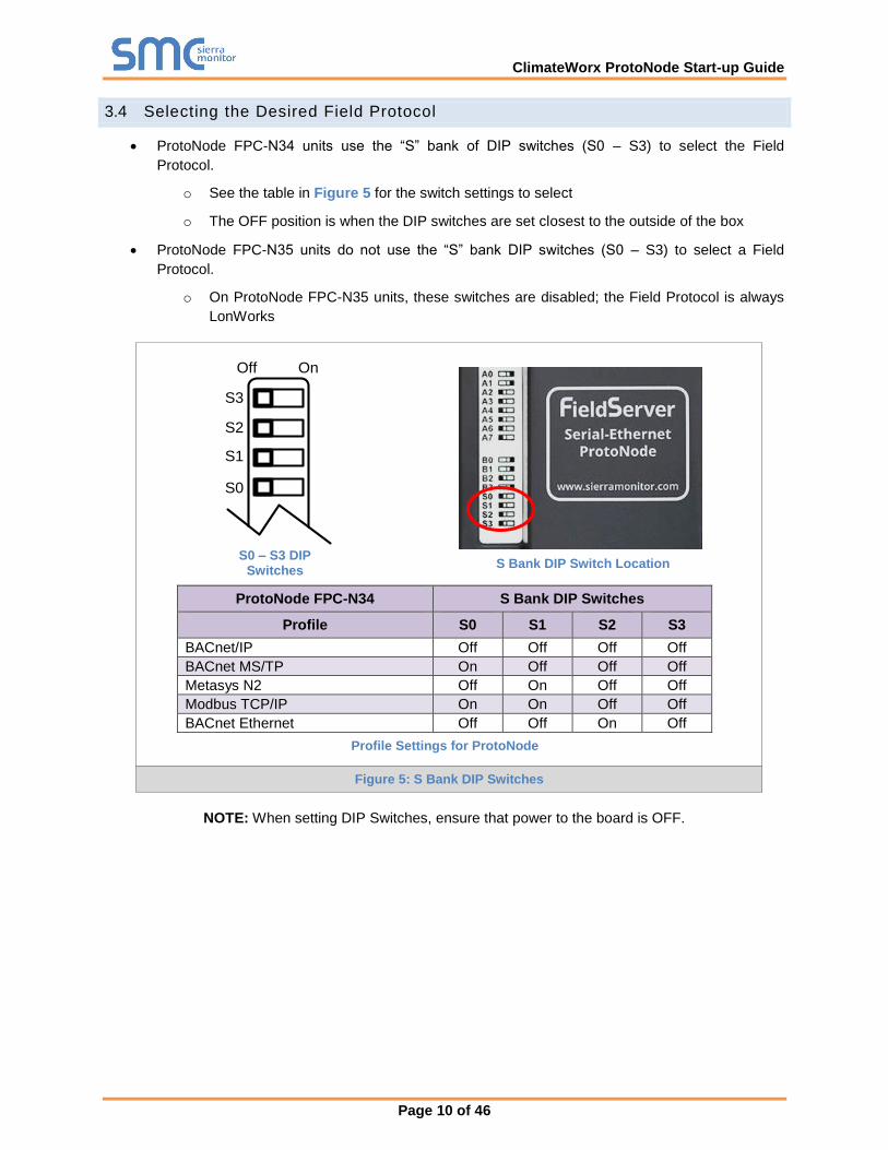
ProtoNode FPC-N34 units use the “S” bank of DIP switches (S0 – S3) to select the Field
Protocol.
o See the table in Figure 5 for the switch settings to select
o The OFF position is when the DIP switches are set closest to the outside of the box
ProtoNode FPC-N35 units do not use the “S” bank DIP switches (S0 – S3) to select a Field
Protocol.
o On ProtoNode FPC-N35 units, these switches are disabled; the Field Protocol is always
LonWorks
ProtoNode FPC-N34 S Bank DIP Switches
Profile S0 S1 S2 S3
BACnet/IP Off Off Off Off
BACnet MS/TP On Off Off Off
Metasys N2 Off On Off Off
Modbus TCP/IP On On Off Off
BACnet Ethernet Off Off On Off
NOTE: When setting DIP Switches, ensure that power to the board is OFF.
S0 – S3 DIP Switches
S Bank DIP Switch Location
Profile Settings for ProtoNode
Figure 5: S Bank DIP Switches
S0
S1
S2
S3
Off On
ClimateWorx ProtoNode Start-up Guide
Page 11 of 46
3.5 BMS Network Settings: MAC Address, Device Instance and Baud Rate
3.5.1 BACnet MS/TP (FPC-N34): Setting the MAC Address for BMS Network
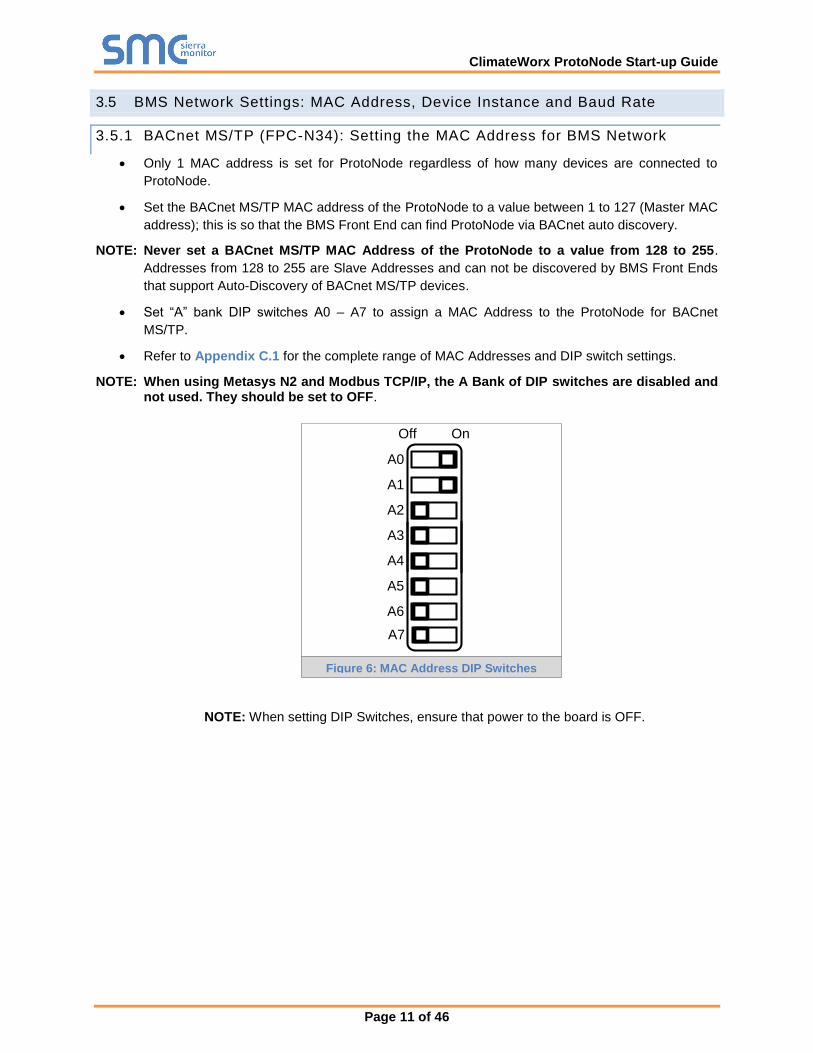
Only 1 MAC address is set for ProtoNode regardless of how many devices are connected to
ProtoNode.
Set the BACnet MS/TP MAC address of the ProtoNode to a value between 1 to 127 (Master MAC
address); this is so that the BMS Front End can find ProtoNode via BACnet auto discovery.
NOTE: Never set a BACnet MS/TP MAC Address of the ProtoNode to a value from 128 to 255.
Addresses from 128 to 255 are Slave Addresses and can not be discovered by BMS Front Ends
that support Auto-Discovery of BACnet MS/TP devices.
Set “A” bank DIP switches A0 – A7 to assign a MAC Address to the ProtoNode for BACnet
MS/TP.
Refer to Appendix C.1 for the complete range of MAC Addresses and DIP switch settings.
NOTE: When using Metasys N2 and Modbus TCP/IP, the A Bank of DIP switches are disabled and not used. They should be set to OFF.
A0
A1
A2
A3
A4
A5
A6
A7
Off On
NOTE: When setting DIP Switches, ensure that power to the board is OFF.
Figure 6: MAC Address DIP Switches
ClimateWorx ProtoNode Start-up Guide
Page 12 of 46
3.5.2 BACnet MS/TP (FPC-N34): Setting the Baud Rate for BMS Network
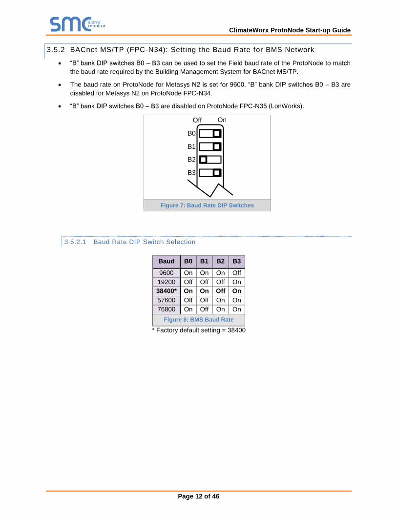
“B” bank DIP switches B0 – B3 can be used to set the Field baud rate of the ProtoNode to match
the baud rate required by the Building Management System for BACnet MS/TP.
The baud rate on ProtoNode for Metasys N2 is set for 9600. “B” bank DIP switches B0 – B3 are
disabled for Metasys N2 on ProtoNode FPC-N34.
“B” bank DIP switches B0 – B3 are disabled on ProtoNode FPC-N35 (LonWorks).
B0
B1
B2
B3
Off On
3.5.2.1 Baud Rate DIP Switch Selection
Baud B0 B1 B2 B3
9600 On On On Off
19200 Off Off Off On
38400* On On Off On
57600 Off Off On On
76800 On Off On On
Figure 8: BMS Baud Rate
* Factory default setting = 38400
Figure 7: Baud Rate DIP Switches
ClimateWorx ProtoNode Start-up Guide
Page 13 of 46
4 INTERFACING PROTONODE TO DEVICES
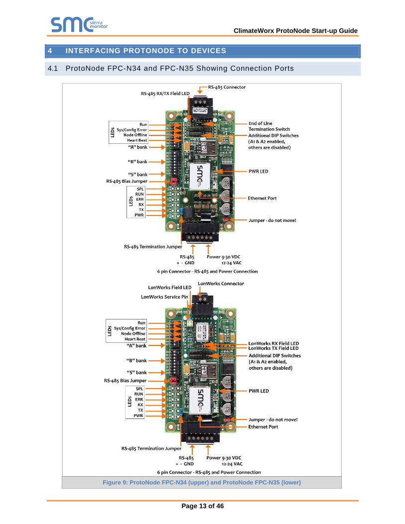
4.1 ProtoNode FPC-N34 and FPC-N35 Showing Connection Ports
Figure 9: ProtoNode FPC-N34 (upper) and ProtoNode FPC-N35 (lower)
ClimateWorx ProtoNode Start-up Guide
Page 14 of 46
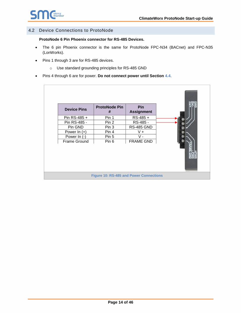
4.2 Device Connections to ProtoNode
ProtoNode 6 Pin Phoenix connector for RS-485 Devices.
The 6 pin Phoenix connector is the same for ProtoNode FPC-N34 (BACnet) and FPC-N35
(LonWorks).
Pins 1 through 3 are for RS-485 devices.
o Use standard grounding principles for RS-485 GND
Pins 4 through 6 are for power. Do not connect power until Section 4.4.
Device Pins ProtoNode Pin
# Pin
Assignment
Pin RS-485 + Pin 1 RS-485 +
Pin RS-485 - Pin 2 RS-485 -
Pin GND Pin 3 RS-485 GND
Power In (+) Pin 4 V +
Power In (-) Pin 5 V -
Frame Ground Pin 6 FRAME GND
Figure 10: RS-485 and Power Connections
ClimateWorx ProtoNode Start-up Guide
Page 15 of 46
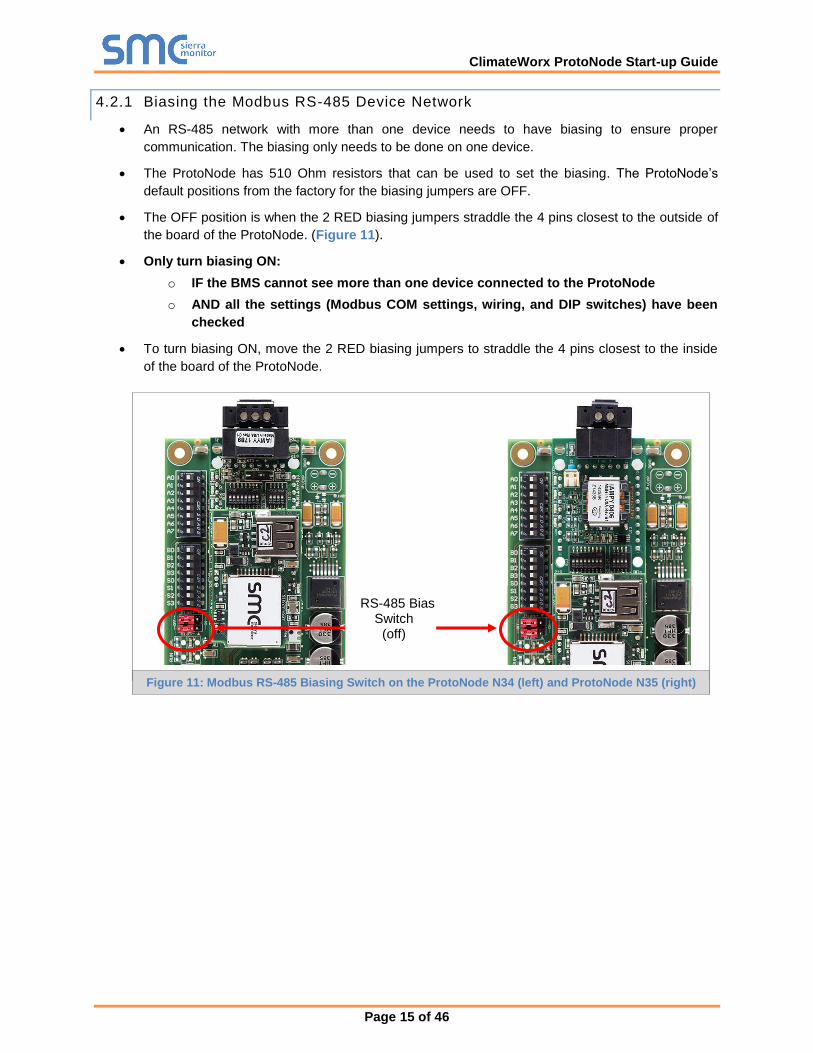
4.2.1 Biasing the Modbus RS-485 Device Network
An RS-485 network with more than one device needs to have biasing to ensure proper
communication. The biasing only needs to be done on one device.
The ProtoNode has 510 Ohm resistors that can be used to set the biasing. The ProtoNode’s
default positions from the factory for the biasing jumpers are OFF.
The OFF position is when the 2 RED biasing jumpers straddle the 4 pins closest to the outside of
the board of the ProtoNode. (Figure 11).
Only turn biasing ON:
o IF the BMS cannot see more than one device connected to the ProtoNode
o AND all the settings (Modbus COM settings, wiring, and DIP switches) have been
checked
To turn biasing ON, move the 2 RED biasing jumpers to straddle the 4 pins closest to the inside
of the board of the ProtoNode.
RS-485 Bias Switch
(off)
Figure 11: Modbus RS-485 Biasing Switch on the ProtoNode N34 (left) and ProtoNode N35 (right)
ClimateWorx ProtoNode Start-up Guide
Page 16 of 46
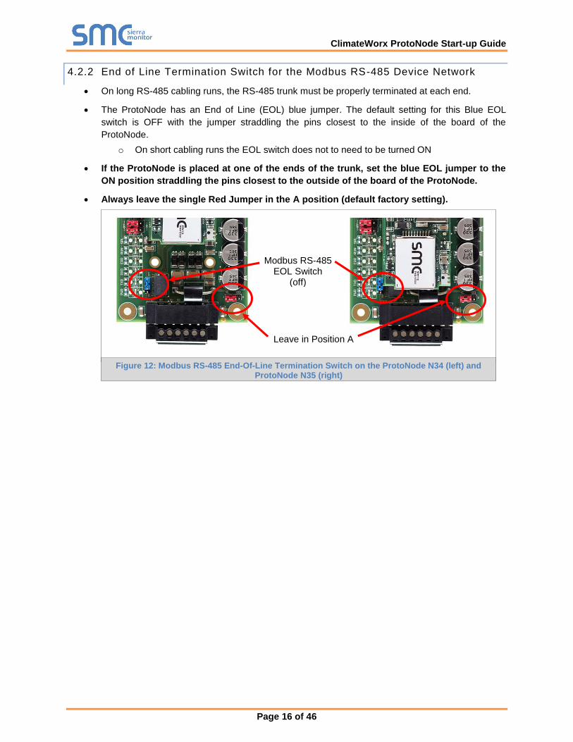
4.2.2 End of Line Termination Switch for the Modbus RS-485 Device Network
On long RS-485 cabling runs, the RS-485 trunk must be properly terminated at each end.
The ProtoNode has an End of Line (EOL) blue jumper. The default setting for this Blue EOL
switch is OFF with the jumper straddling the pins closest to the inside of the board of the
ProtoNode.
o On short cabling runs the EOL switch does not to need to be turned ON
If the ProtoNode is placed at one of the ends of the trunk, set the blue EOL jumper to the
ON position straddling the pins closest to the outside of the board of the ProtoNode.
Always leave the single Red Jumper in the A position (default factory setting).
Modbus RS-485 EOL Switch
(off)
Leave in Position A
Figure 12: Modbus RS-485 End-Of-Line Termination Switch on the ProtoNode N34 (left) and ProtoNode N35 (right)
ClimateWorx ProtoNode Start-up Guide
Page 17 of 46
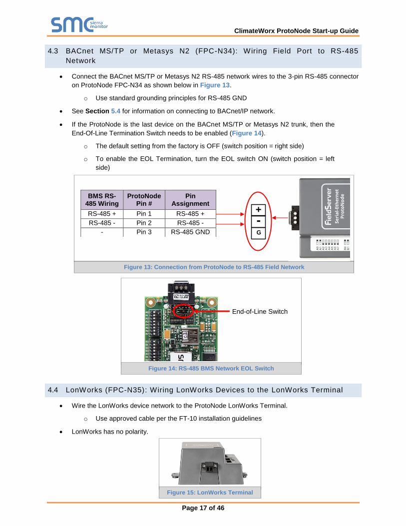
4.3 BACnet MS/TP or Metasys N2 (FPC-N34): Wiring Field Port to RS-485
Network
Connect the BACnet MS/TP or Metasys N2 RS-485 network wires to the 3-pin RS-485 connector
on ProtoNode FPC-N34 as shown below in Figure 13.
o Use standard grounding principles for RS-485 GND
See Section 5.4 for information on connecting to BACnet/IP network.
If the ProtoNode is the last device on the BACnet MS/TP or Metasys N2 trunk, then the
End-Of-Line Termination Switch needs to be enabled (Figure 14).
o The default setting from the factory is OFF (switch position = right side)
o To enable the EOL Termination, turn the EOL switch ON (switch position = left
side)
4.4 LonWorks (FPC-N35): Wiring LonWorks Devices to the LonWorks Terminal
Wire the LonWorks device network to the ProtoNode LonWorks Terminal.
o Use approved cable per the FT-10 installation guidelines
LonWorks has no polarity.
BMS RS-485 Wiring
ProtoNode Pin #
Pin Assignment
RS-485 + Pin 1 RS-485 +
RS-485 - Pin 2 RS-485 -
- Pin 3 RS-485 GND
Figure 14: RS-485 BMS Network EOL Switch
Figure 13: Connection from ProtoNode to RS-485 Field Network
End-of-Line Switch
G
-
+
Figure 15: LonWorks Terminal
ClimateWorx ProtoNode Start-up Guide
Page 18 of 46
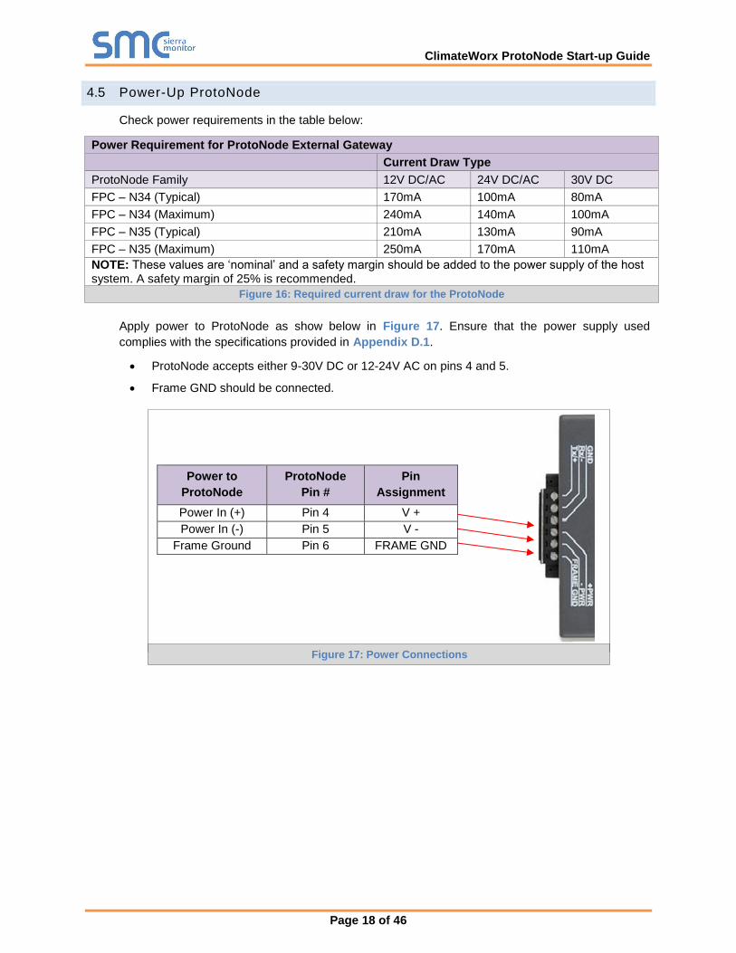
4.5 Power-Up ProtoNode
Check power requirements in the table below:
Power Requirement for ProtoNode External Gateway
Current Draw Type
ProtoNode Family 12V DC/AC 24V DC/AC 30V DC
FPC – N34 (Typical) 170mA 100mA 80mA
FPC – N34 (Maximum) 240mA 140mA 100mA
FPC – N35 (Typical) 210mA 130mA 90mA
FPC – N35 (Maximum) 250mA 170mA 110mA
NOTE: These values are ‘nominal’ and a safety margin should be added to the power supply of the host system. A safety margin of 25% is recommended.
Figure 16: Required current draw for the ProtoNode
Apply power to ProtoNode as show below in Figure 17. Ensure that the power supply used
complies with the specifications provided in Appendix D.1.
ProtoNode accepts either 9-30V DC or 12-24V AC on pins 4 and 5.
Frame GND should be connected.
Power to
ProtoNode
ProtoNode
Pin #
Pin
Assignment
Power In (+) Pin 4 V +
Power In (-) Pin 5 V -
Frame Ground Pin 6 FRAME GND
Figure 17: Power Connections
ClimateWorx ProtoNode Start-up Guide
Page 19 of 46
5 USE PROTONODE WEB CONFIGURATOR TO SETUP THE GATEWAY
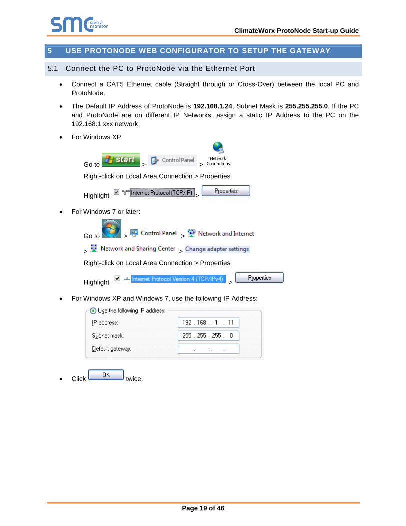
5.1 Connect the PC to ProtoNode via the Ethernet Port
Connect a CAT5 Ethernet cable (Straight through or Cross-Over) between the local PC and
ProtoNode.
The Default IP Address of ProtoNode is 192.168.1.24, Subnet Mask is 255.255.255.0. If the PC
and ProtoNode are on different IP Networks, assign a static IP Address to the PC on the
192.168.1.xxx network.
For Windows XP:
Go to > >
Right-click on Local Area Connection > Properties
Highlight >
For Windows 7 or later:
Go to > >
> >
Right-click on Local Area Connection > Properties
Highlight >
For Windows XP and Windows 7, use the following IP Address:
Click twice.
ClimateWorx ProtoNode Start-up Guide
Page 20 of 46
5.2 Connecting to ProtoNode Web Configurator
After setting a local PC on the same subnet as the ProtoNode (Section 5.1), open a web browser
on the PC and enter the IP Address of the ProtoNode; the default address is 192.168.1.24.
NOTE: If the IP Address of the ProtoNode has been changed by previous configuration, the assigned IP
Address can be discovered using the FS Toolbox utility. See Appendix A.1 for instructions.
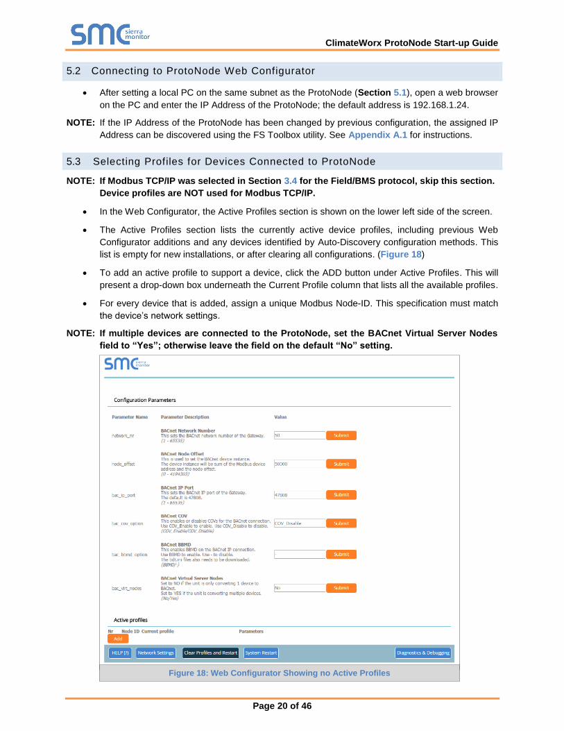
5.3 Selecting Profiles for Devices Connected to ProtoNode
NOTE: If Modbus TCP/IP was selected in Section 3.4 for the Field/BMS protocol, skip this section.
Device profiles are NOT used for Modbus TCP/IP.
In the Web Configurator, the Active Profiles section is shown on the lower left side of the screen.
The Active Profiles section lists the currently active device profiles, including previous Web
Configurator additions and any devices identified by Auto-Discovery configuration methods. This
list is empty for new installations, or after clearing all configurations. (Figure 18)
To add an active profile to support a device, click the ADD button under Active Profiles. This will
present a drop-down box underneath the Current Profile column that lists all the available profiles.
For every device that is added, assign a unique Modbus Node-ID. This specification must match
the device’s network settings.
NOTE: If multiple devices are connected to the ProtoNode, set the BACnet Virtual Server Nodes
field to “Yes”; otherwise leave the field on the default “No” setting.
Figure 18: Web Configurator Showing no Active Profiles

ClimateWorx ProtoNode Start-up Guide
Page 21 of 46
Once the Profile for the device has been selected from the drop-down list, enter the value of the
device’s Modbus Node-ID which was assigned in Section 3.3.2.
Then press the “Submit” button to add the Profile to the list of devices to be configured.
Repeat this process until all the devices have been added.
Completed additions are listed under “Active Profiles” as shown in Figure 19.
Figure 19: Web Configurator Showing Active Profile Additions

ClimateWorx ProtoNode Start-up Guide
Page 22 of 46
5.4 BACnet/IP and Modbus TCP/IP: Setting IP Address for Field Network
After setting a local PC to the same subnet as the ProtoNode (Section 5.1), open a web browser
on the PC and enter the IP Address of the ProtoNode; the default address is 192.168.1.24.
The Web Configurator is displayed as the landing page. (Figure 20)
To access the Web GUI, click on the “Diagnostics & Debugging” button in the bottom right
side of the page.
Figure 20: Web Configurator Screen with Active Profiles

ClimateWorx ProtoNode Start-up Guide
Page 23 of 46
From the Web GUI landing page, click on “Setup” to expand the navigation tree and then select
“Network Settings” to access the IP Settings menu. (Figure 21)
Modify the IP Address (N1 IP Address field) of the ProtoNode Ethernet port.
If necessary, change the Netmask (N1 Netmask field).
Type in a new Subnet Mask.
If necessary, change the IP Gateway (Default Gateway field).
Type in a new IP Gateway.
NOTE: If the ProtoNode is connected to a router, the IP Gateway of the ProtoNode should be set to the
IP Address of that router.
Reset ProtoNode.
Unplug Ethernet cable from PC and connect it to the network hub or router.
Record the IP Address assigned to the ProtoNode for future reference.
NOTE: For FieldPoP™ information, refer to the FieldPoP™ Device Cloud Start-up Guide online at
the Sierra Monitor.com Resource Center.
www.sierramonitor.com/customer-care/resource-center
Figure 21: Changing IP Address via Web GUI
ClimateWorx ProtoNode Start-up Guide
Page 24 of 46
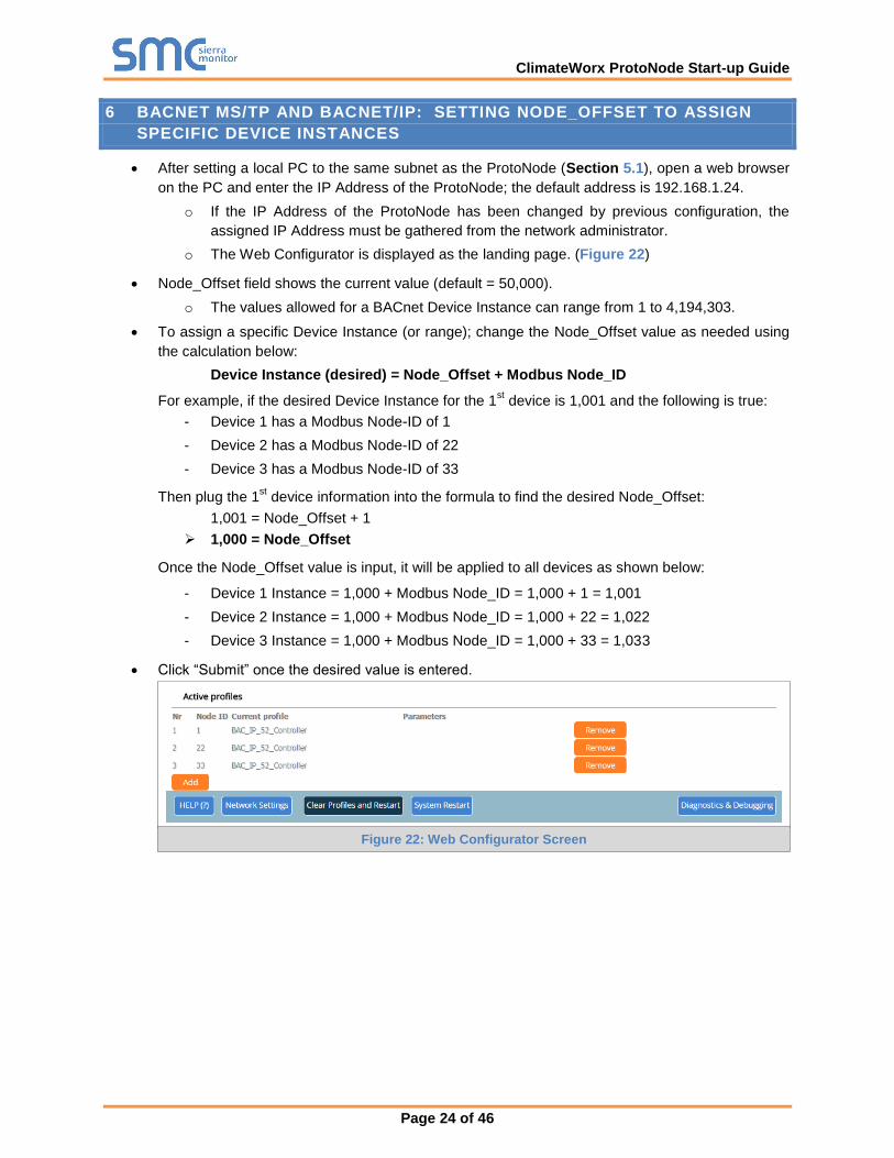
6 BACNET MS/TP AND BACNET/IP: SETTING NODE_OFFSET TO ASSIGN
SPECIFIC DEVICE INSTANCES
After setting a local PC to the same subnet as the ProtoNode (Section 5.1), open a web browser
on the PC and enter the IP Address of the ProtoNode; the default address is 192.168.1.24.
o If the IP Address of the ProtoNode has been changed by previous configuration, the
assigned IP Address must be gathered from the network administrator.
o The Web Configurator is displayed as the landing page. (Figure 22)
Node_Offset field shows the current value (default = 50,000).
o The values allowed for a BACnet Device Instance can range from 1 to 4,194,303.
To assign a specific Device Instance (or range); change the Node_Offset value as needed using
the calculation below:
Device Instance (desired) = Node_Offset + Modbus Node_ID
For example, if the desired Device Instance for the 1st device is 1,001 and the following is true:
- Device 1 has a Modbus Node-ID of 1
- Device 2 has a Modbus Node-ID of 22
- Device 3 has a Modbus Node-ID of 33
Then plug the 1st device information into the formula to find the desired Node_Offset:
1,001 = Node_Offset + 1
1,000 = Node_Offset
Once the Node_Offset value is input, it will be applied to all devices as shown below:
- Device 1 Instance = 1,000 + Modbus Node_ID = 1,000 + 1 = 1,001
- Device 2 Instance = 1,000 + Modbus Node_ID = 1,000 + 22 = 1,022
- Device 3 Instance = 1,000 + Modbus Node_ID = 1,000 + 33 = 1,033
Click “Submit” once the desired value is entered.
Figure 22: Web Configurator Screen

ClimateWorx ProtoNode Start-up Guide
Page 25 of 46
7 HOW TO START THE INSTALLATION OVER: CLEARING PROFILES
After setting a local PC to the same subnet as the ProtoNode (Section 5.1), open a web browser
on the PC and enter the IP Address of the ProtoNode; the default address is 192.168.1.24.
If the IP Address of the ProtoNode has been changed by previous configuration, the assigned IP
Address must be gathered from the network administrator.
The Web Configurator is displayed as the landing page.
At the bottom-left of the page, click the “Clear Profiles and Restart” button.
Once restart is complete, all past profiles discovered and/or added via Web configurator are
deleted. The unit can now be reinstalled.
ClimateWorx ProtoNode Start-up Guide
Page 26 of 46
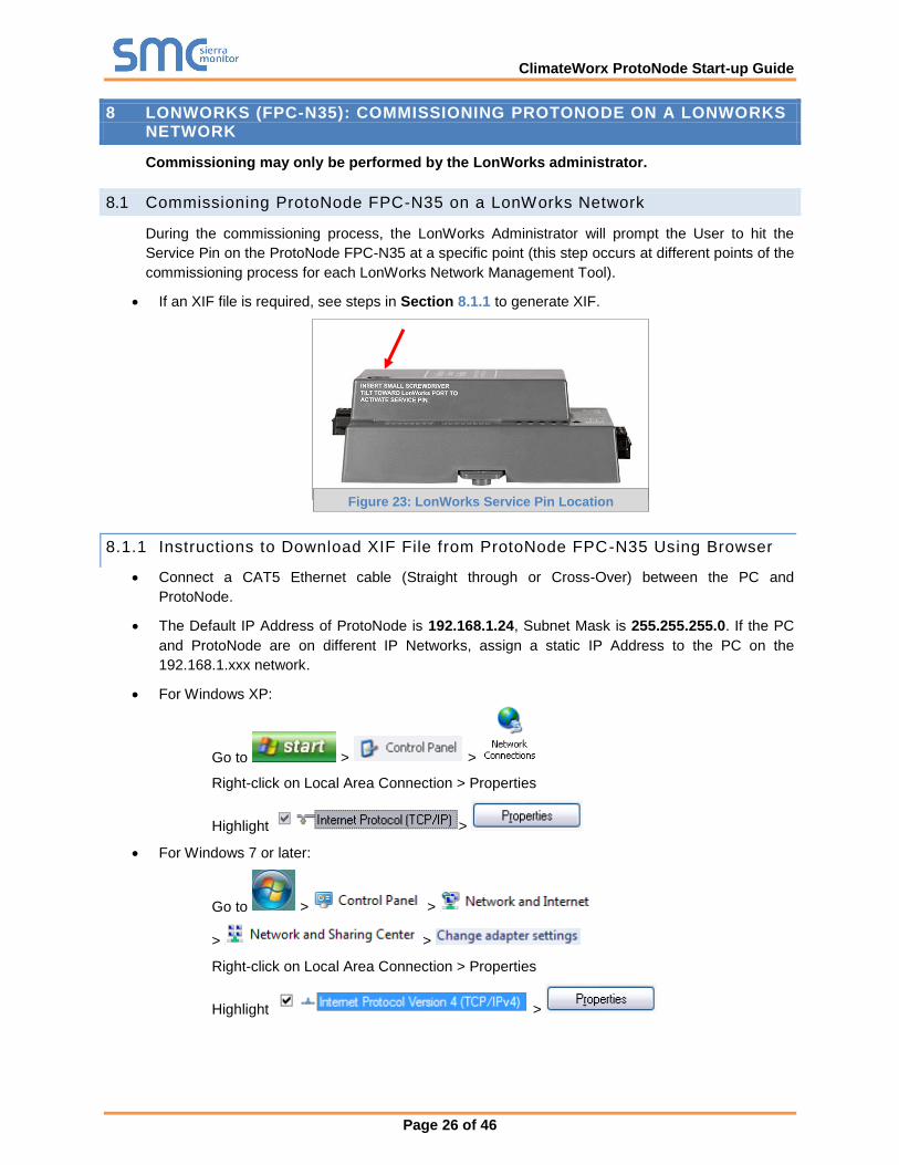
8 LONWORKS (FPC-N35): COMMISSIONING PROTONODE ON A LONWORKS NETWORK
Commissioning may only be performed by the LonWorks administrator.
8.1 Commissioning ProtoNode FPC-N35 on a LonWorks Network
During the commissioning process, the LonWorks Administrator will prompt the User to hit the
Service Pin on the ProtoNode FPC-N35 at a specific point (this step occurs at different points of the
commissioning process for each LonWorks Network Management Tool).
If an XIF file is required, see steps in Section 8.1.1 to generate XIF.
8.1.1 Instructions to Download XIF File from ProtoNode FPC-N35 Using Browser
Connect a CAT5 Ethernet cable (Straight through or Cross-Over) between the PC and
ProtoNode.
The Default IP Address of ProtoNode is 192.168.1.24, Subnet Mask is 255.255.255.0. If the PC
and ProtoNode are on different IP Networks, assign a static IP Address to the PC on the
192.168.1.xxx network.
For Windows XP:
Go to > >
Right-click on Local Area Connection > Properties
Highlight >
For Windows 7 or later:
Go to > >
> >
Right-click on Local Area Connection > Properties
Highlight >
Figure 23: LonWorks Service Pin Location

ClimateWorx ProtoNode Start-up Guide
Page 27 of 46
For Windows XP and Windows 7, use the following IP Address:
Click twice.
Open a web browser and go to the following address: [IP Address of ProtoNode]/fserver.xif
o Example: 192.168.1.24/fserver.xif
If the web browser prompts to save the file, save the file onto the PC. If the web browser displays
the xif file as a web page, save the file onto the local PC as “fserver.xif”.
Figure 24: Sample of Fserver.XIF File Generated
ClimateWorx ProtoNode Start-up Guide
Page 28 of 46
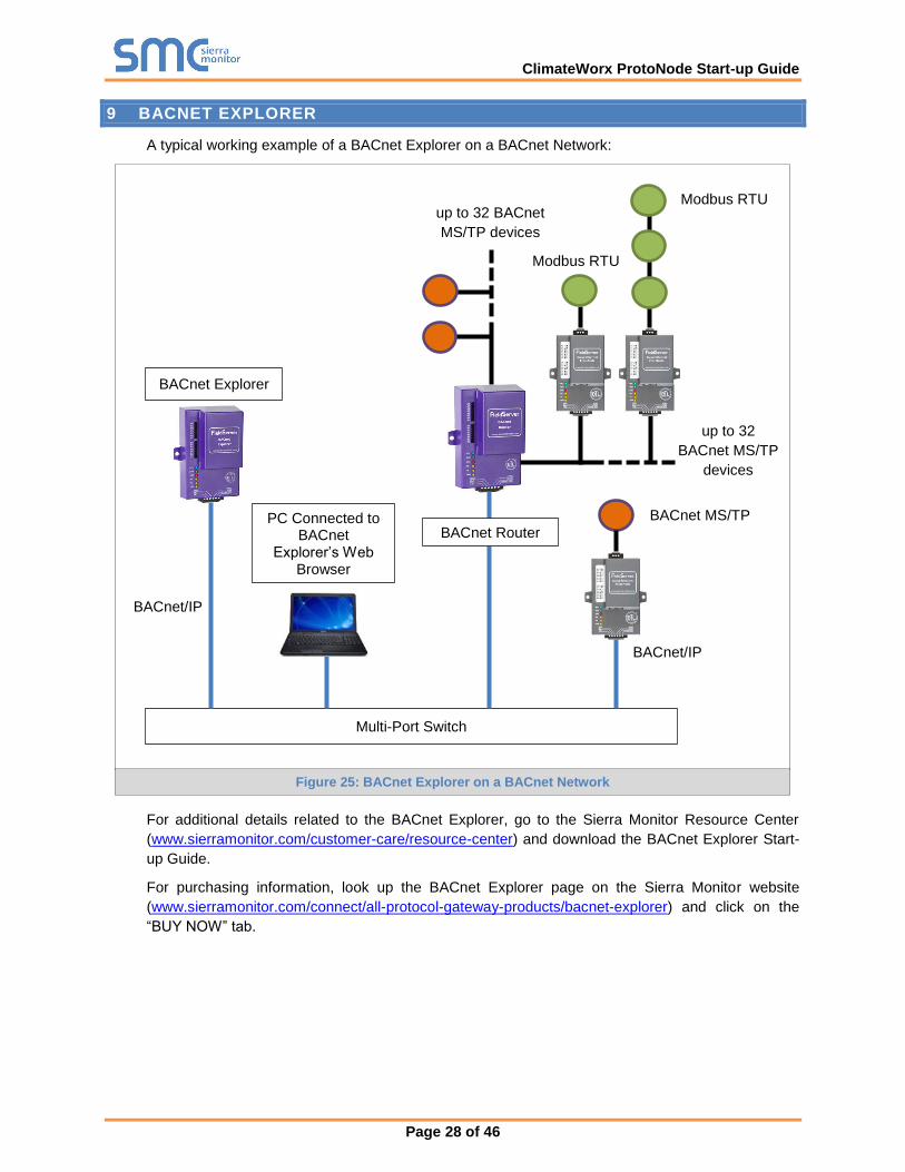
9 BACNET EXPLORER
A typical working example of a BACnet Explorer on a BACnet Network:
For additional details related to the BACnet Explorer, go to the Sierra Monitor Resource Center
(www.sierramonitor.com/customer-care/resource-center) and download the BACnet Explorer Start-
up Guide.
For purchasing information, look up the BACnet Explorer page on the Sierra Monitor website
(www.sierramonitor.com/connect/all-protocol-gateway-products/bacnet-explorer) and click on the
“BUY NOW” tab.
Multi-Port Switch
BACnet MS/TP
BACnet/IP
PC Connected to BACnet
Explorer’s Web Browser
BACnet/IP
BACnet Explorer
Modbus RTU up to 32 BACnet
MS/TP devices
BACnet Router
up to 32
BACnet MS/TP
devices
Modbus RTU
Figure 25: BACnet Explorer on a BACnet Network
ClimateWorx ProtoNode Start-up Guide
Page 29 of 46
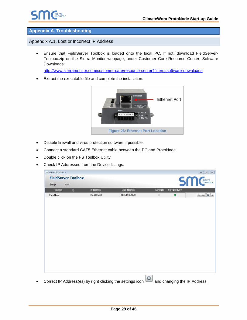
Appendix A. Troubleshooting
Lost or Incorrect IP Address Appendix A.1.
Ensure that FieldServer Toolbox is loaded onto the local PC. If not, download FieldServer-
Toolbox.zip on the Sierra Monitor webpage, under Customer Care-Resource Center, Software
Downloads:
http://www.sierramonitor.com/customer-care/resource-center?filters=software-downloads
Extract the executable file and complete the installation.
Disable firewall and virus protection software if possible.
Connect a standard CAT5 Ethernet cable between the PC and ProtoNode.
Double click on the FS Toolbox Utility.
Check IP Addresses from the Device listings.
Correct IP Address(es) by right clicking the settings icon and changing the IP Address.
Ethernet Port
Figure 26: Ethernet Port Location
ClimateWorx ProtoNode Start-up Guide
Page 30 of 46
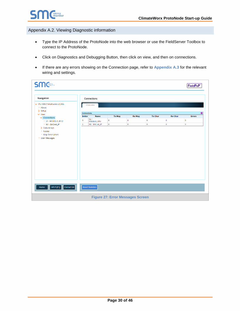
Viewing Diagnostic information Appendix A.2.
Type the IP Address of the ProtoNode into the web browser or use the FieldServer Toolbox to
connect to the ProtoNode.
Click on Diagnostics and Debugging Button, then click on view, and then on connections.
If there are any errors showing on the Connection page, refer to Appendix A.3 for the relevant
wiring and settings.
Figure 27: Error Messages Screen

ClimateWorx ProtoNode Start-up Guide
Page 31 of 46
Check Wiring and Settings Appendix A.3.
No COMS on Modbus RTU side. If the Tx/Rx LEDs are not flashing rapidly then there is a COM
issue. To fix, check the following:
o Visual observations of LEDs on ProtoNode (Appendix A.4)
o Check baud rate, parity, data bits, stop bits
o Check device address
o Verify wiring
o Verify device is connected to the same subnet as the ProtoNode
o Verify the Modbus device was discovered in Web Configurator (Section 5.2)
Field COM problems:
o If Ethernet protocols are used, observe Ethernet LEDs on the ProtoNode (Appendix A.4)
o Check dipswitch settings (using correct baud rate and device instance)
o Verify IP Address setting
o Verify wiring
NOTE: If the problem persists, a Diagnostic Capture needs to be taken and sent to support.
(Appendix A.5)
ClimateWorx ProtoNode Start-up Guide
Page 32 of 46
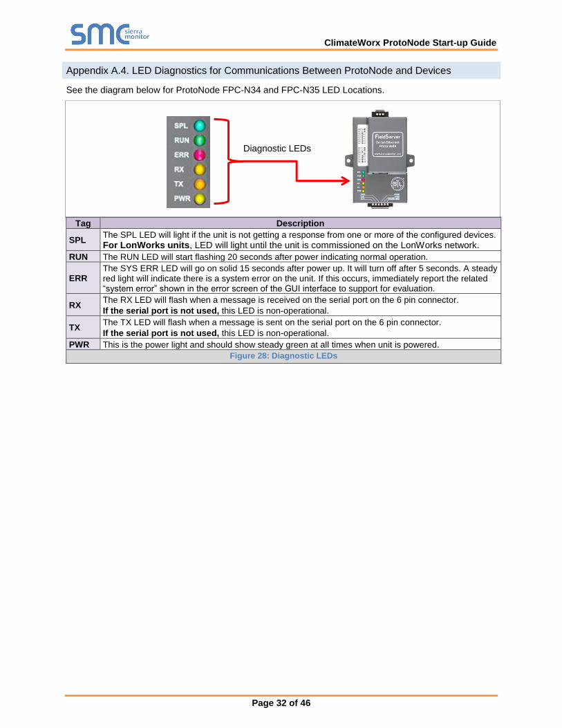
LED Diagnostics for Communications Between ProtoNode and Devices Appendix A.4.
See the diagram below for ProtoNode FPC-N34 and FPC-N35 LED Locations.
Tag Description
SPL The SPL LED will light if the unit is not getting a response from one or more of the configured devices.
For LonWorks units, LED will light until the unit is commissioned on the LonWorks network.
RUN The RUN LED will start flashing 20 seconds after power indicating normal operation.
ERR The SYS ERR LED will go on solid 15 seconds after power up. It will turn off after 5 seconds. A steady red light will indicate there is a system error on the unit. If this occurs, immediately report the related “system error” shown in the error screen of the GUI interface to support for evaluation.
RX The RX LED will flash when a message is received on the serial port on the 6 pin connector.
If the serial port is not used, this LED is non-operational.
TX The TX LED will flash when a message is sent on the serial port on the 6 pin connector.
If the serial port is not used, this LED is non-operational.
PWR This is the power light and should show steady green at all times when unit is powered.
Figure 28: Diagnostic LEDs
Diagnostic LEDs
ClimateWorx ProtoNode Start-up Guide
Page 33 of 46
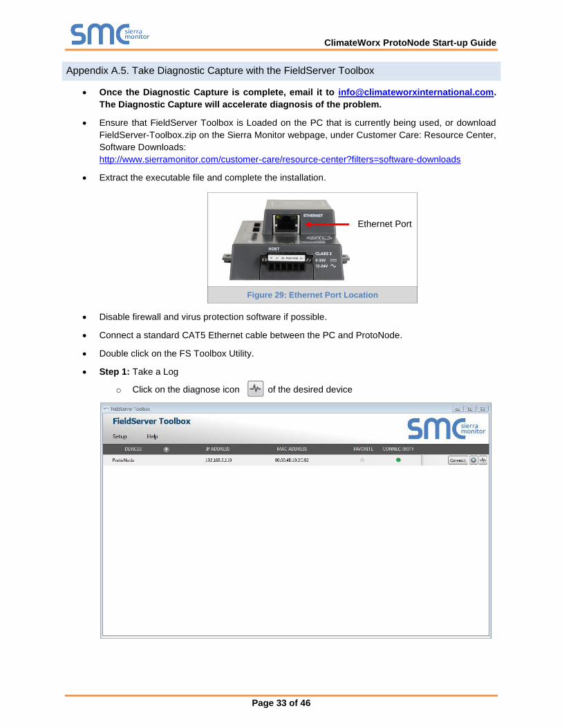
Take Diagnostic Capture with the FieldServer Toolbox Appendix A.5.
Once the Diagnostic Capture is complete, email it to [email protected].
The Diagnostic Capture will accelerate diagnosis of the problem.
Ensure that FieldServer Toolbox is Loaded on the PC that is currently being used, or download
FieldServer-Toolbox.zip on the Sierra Monitor webpage, under Customer Care: Resource Center,
Software Downloads:
http://www.sierramonitor.com/customer-care/resource-center?filters=software-downloads
Extract the executable file and complete the installation.
Disable firewall and virus protection software if possible.
Connect a standard CAT5 Ethernet cable between the PC and ProtoNode.
Double click on the FS Toolbox Utility.
Step 1: Take a Log
o Click on the diagnose icon of the desired device
Ethernet Port
Figure 29: Ethernet Port Location
ClimateWorx ProtoNode Start-up Guide
Page 34 of 46
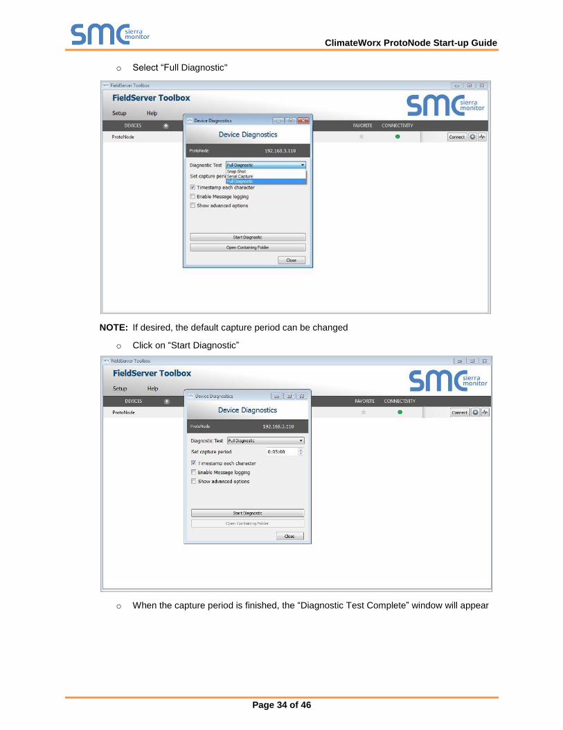
o Select “Full Diagnostic"
NOTE: If desired, the default capture period can be changed
o Click on “Start Diagnostic”
o When the capture period is finished, the “Diagnostic Test Complete” window will appear
ClimateWorx ProtoNode Start-up Guide
Page 35 of 46
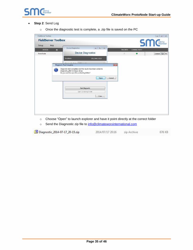
Step 2: Send Log
o Once the diagnostic test is complete, a .zip file is saved on the PC
o Choose “Open” to launch explorer and have it point directly at the correct folder
o Send the Diagnostic zip file to [email protected]

ClimateWorx ProtoNode Start-up Guide
Page 36 of 46
Update Firmware Appendix A.6.
To load a new version of the firmware, follow these instructions:
1. Extract and save the new file onto the local PC.
2. Open a web browser and type the IP Address of the FieldServer in the address bar.
o Default IP Address is 192.168.1.24
o Use the FS Toolbox utility if the IP Address is unknown (Appendix A.1)
3. Click on the “Diagnostics & Debugging” button.
4. In the Navigation Tree on the left hand side, do the following:
a. Click on “Setup”
b. Click on “File Transfer”
c. Click on the “Firmware” tab
5. In the Firmware tab, click on “Choose Files” and select the firmware file extracted in step 1.
6. Click on the orange “Submit” button.
7. When the download is complete, click on the “System Restart” button.
BACnet: Setting Network_Number for more than one ProtoNode on Subnet Appendix A.7.
For both BACnet MS/TP and BACnet/IP, if more than one ProtoNode is connected to the same subnet,
they must be assigned unique Network_Number values.
On the main Web Configuration screen, update the Network Number with the “network_nr” field and click
submit. The default value is 50.
Figure 30: Web Configurator – Setting Network Number for BACnet

ClimateWorx ProtoNode Start-up Guide
Page 37 of 46
Securing ProtoNode with Passwords Appendix A.8.
Access to the ProtoNode can be restricted by enabling a password. There are 2 access levels defined by
2 account names: Admin and User.
The Admin account has unrestricted access to the ProtoNode.
The User account can view any ProtoNode information, but cannot make any changes or restart
the ProtoNode.
The password needs to be a minimum of eight characters and is case sensitive.
If the password is lost, click cancel on the password authentication popup window, and email the
password recovery token to [email protected] to receive a temporary password from the
support team. Access the ProtoNode to set a new password.
ClimateWorx ProtoNode Start-up Guide
Page 38 of 46
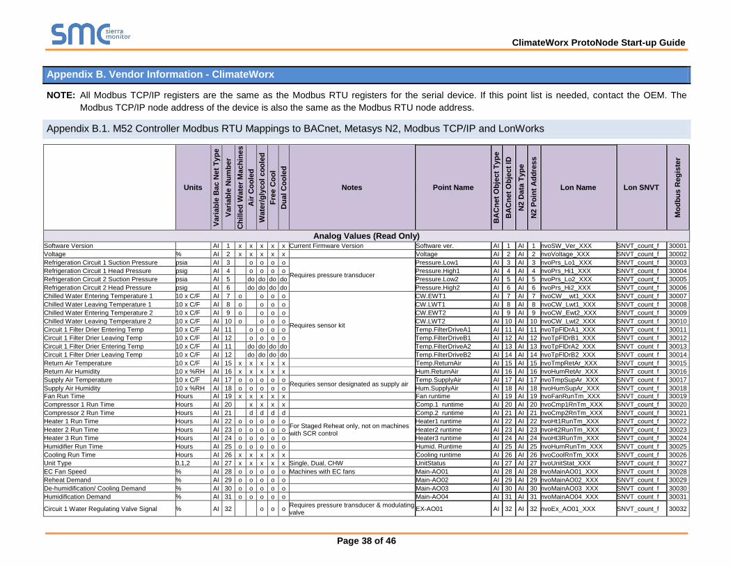
Appendix B. Vendor Information - ClimateWorx
NOTE: All Modbus TCP/IP registers are the same as the Modbus RTU registers for the serial device. If this point list is needed, contact the OEM. The
Modbus TCP/IP node address of the device is also the same as the Modbus RTU node address.
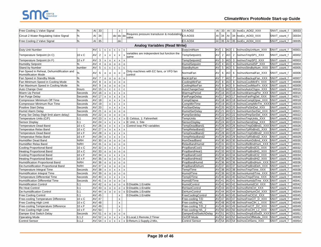
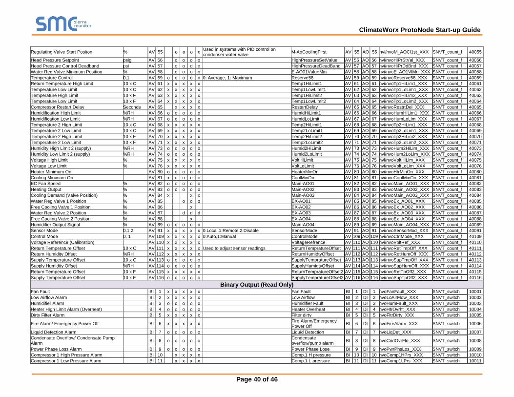
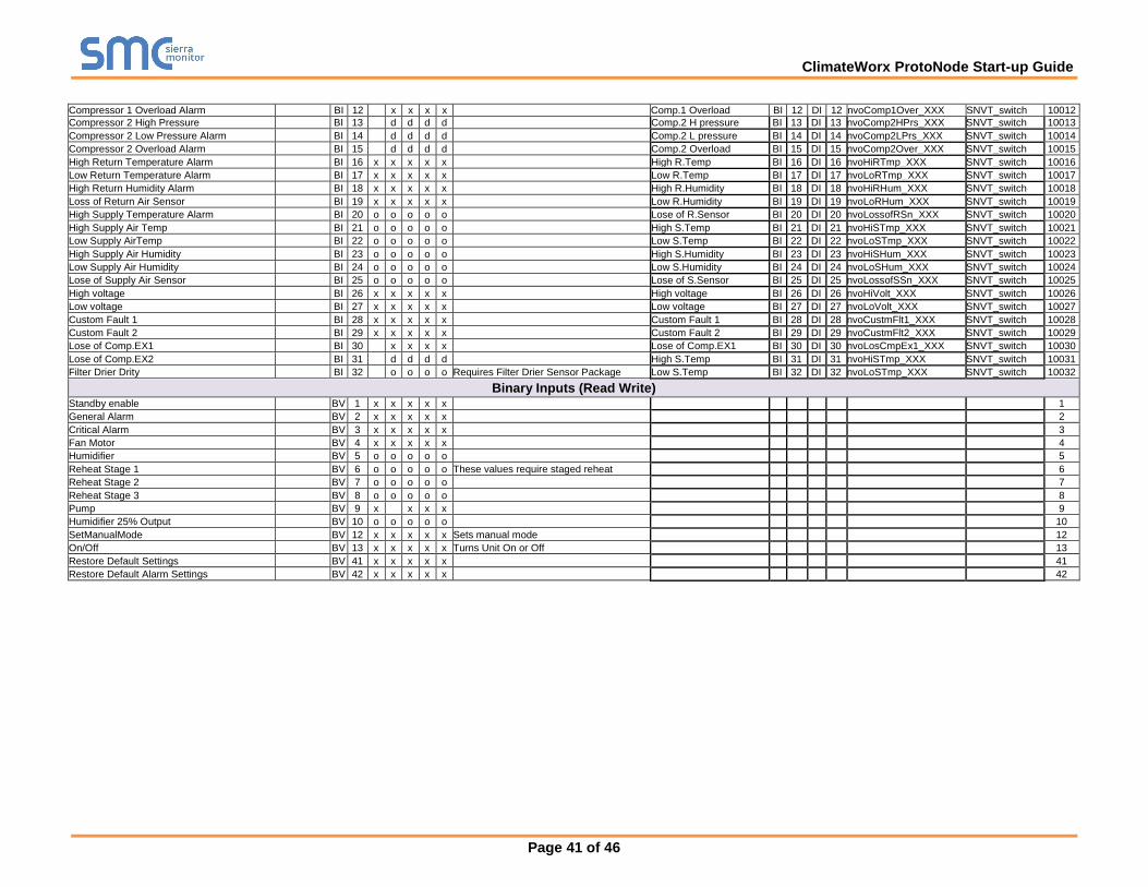
M52 Controller Modbus RTU Mappings to BACnet, Metasys N2, Modbus TCP/IP and LonWorks Appendix B.1.
Units
Vari
ab
le B
ac N
et
Ty
pe
Vari
ab
le N
um
be
r
Ch
ille
d W
ate
r M
ach
ine
s
Air
Co
ole
d
Wate
r/g
lyco
l co
ole
d
Fre
e C
oo
l
Du
al
Co
ole
d
Notes Point Name
BA
Cn
et
Ob
ject
Ty
pe
BA
Cn
et
Ob
ject
ID
N2 D
ata
Ty
pe
N2 P
oin
t A
dd
ress
Lon Name Lon SNVT
Mo
db
us
Reg
iste
r
Analog Values (Read Only) Software Version AI 1 x x x x x Current Firmware Version Software ver. AI 1 AI 1 nvoSW_Ver_XXX SNVT_count_f 30001
Voltage % AI 2 x x x x x Voltage AI 2 AI 2 nvoVoltage_XXX SNVT_count_f 30002
Refrigeration Circuit 1 Suction Pressure psia AI 3
o o o o
Requires pressure transducer
Pressure.Low1 AI 3 AI 3 nvoPrs_Lo1_XXX SNVT_count_f 30003
Refrigeration Circuit 1 Head Pressure psig AI 4
o o o o Pressure.High1 AI 4 AI 4 nvoPrs_Hi1_XXX SNVT_count_f 30004
Refrigeration Circuit 2 Suction Pressure psia AI 5
do do do do Pressure.Low2 AI 5 AI 5 nvoPrs_Lo2_XXX SNVT_count_f 30005
Refrigeration Circuit 2 Head Pressure psig AI 6
do do do do Pressure.High2 AI 6 AI 6 nvoPrs_Hi2_XXX SNVT_count_f 30006
Chilled Water Entering Temperature 1 10 x C/F AI 7 o
o o o
Requires sensor kit
CW.EWT1 AI 7 AI 7 nvoCW__wt1_XXX SNVT_count_f 30007
Chilled Water Leaving Temperature 1 10 x C/F AI 8 o
o o o CW.LWT1 AI 8 AI 8 nvoCW_Lwt1_XXX SNVT_count_f 30008
Chilled Water Entering Temperature 2 10 x C/F AI 9 o
o o o CW.EWT2 AI 9 AI 9 nvoCW_Ewt2_XXX SNVT_count_f 30009
Chilled Water Leaving Temperature 2 10 x C/F AI 10 o
o o o CW.LWT2 AI 10 AI 10 nvoCW_Lwt2_XXX SNVT_count_f 30010
Circuit 1 Filter Drier Entering Temp 10 x C/F AI 11
o o o o Temp.FilterDriveA1 AI 11 AI 11 nvoTpFlDrA1_XXX SNVT_count_f 30011
Circuit 1 Filter Drier Leaving Temp 10 x C/F AI 12
o o o o Temp.FilterDriveB1 AI 12 AI 12 nvoTpFlDrB1_XXX SNVT_count_f 30012
Circuit 1 Filter Drier Entering Temp 10 x C/F AI 11
do do do do Temp.FilterDriveA2 AI 13 AI 13 nvoTpFlDrA2_XXX SNVT_count_f 30013
Circuit 1 Filter Drier Leaving Temp 10 x C/F AI 12
do do do do Temp.FilterDriveB2 AI 14 AI 14 nvoTpFlDrB2_XXX SNVT_count_f 30014
Return Air Temperature 10 x C/F AI 15 x x x x x Temp.ReturnAir AI 15 AI 15 nvoTmpRetAr_XXX SNVT_count_f 30015
Return Air Humidity 10 x %RH AI 16 x x x x x Hum.ReturnAir AI 16 AI 16 nvoHumRetAr_XXX SNVT_count_f 30016
Supply Air Temperature 10 x C/F AI 17 o o o o o Requries sensor designated as supply air
Temp.SupplyAir AI 17 AI 17 nvoTmpSupAr_XXX SNVT_count_f 30017
Supply Air Humidity 10 x %RH AI 18 o o o o o Hum.SupplyAir AI 18 AI 18 nvoHumSupAr_XXX SNVT_count_f 30018
Fan Run Time Hours AI 19 x x x x x Fan runtime AI 19 AI 19 nvoFanRunTm_XXX SNVT_count_f 30019
Compressor 1 Run Time Hours AI 20
x x x x Comp.1 runtime AI 20 AI 20 nvoCmp1RnTm_XXX SNVT_count_f 30020
Compressor 2 Run Time Hours AI 21
d d d d Comp.2 runtime AI 21 AI 21 nvoCmp2RnTm_XXX SNVT_count_f 30021
Heater 1 Run Time Hours AI 22 o o o o o For Staged Reheat only, not on machines with SCR control
Heater1 runtime AI 22 AI 22 nvoHt1RunTm_XXX SNVT_count_f 30022
Heater 2 Run Time Hours AI 23 o o o o o Heater2 runtime AI 23 AI 23 nvoHt2RunTm_XXX SNVT_count_f 30023
Heater 3 Run Time Hours AI 24 o o o o o Heater3 runtime AI 24 AI 24 nvoHt3RunTm_XXX SNVT_count_f 30024
Humidifier Run Time Hours AI 25 o o o o o Humid. Runtime AI 25 AI 25 nvoHumRunTm_XXX SNVT_count_f 30025
Cooling Run Time Hours AI 26 x x x x x Cooling runtime AI 26 AI 26 nvoCoolRnTm_XXX SNVT_count_f 30026
Unit Type 0,1,2 AI 27 x x x x x Single, Dual, CHW UnitStatus AI 27 AI 27 nvoUnitStat_XXX SNVT_count_f 30027
EC Fan Speed % AI 28 o o o o o Machines with EC fans Main-AO01 AI 28 AI 28 nvoMainAO01_XXX SNVT_count_f 30028
Reheat Demand % AI 29 o o o o o Main-AO02 AI 29 AI 29 nvoMainAO02_XXX SNVT_count_f 30029
De-humidification/ Cooling Demand % AI 30 o o o o o Main-AO03 AI 30 AI 30 nvoMainAO03_XXX SNVT_count_f 30030
Humidification Demand % AI 31 o o o o o Main-AO04 AI 31 AI 31 nvoMainAO04_XXX SNVT_count_f 30031
Circuit 1 Water Regulating Valve Signal % AI 32
o o o Requires pressure transducer & modulating valve
EX-AO01 AI 32 AI 32 nvoEx_AO01_XXX SNVT_count_f 30032
ClimateWorx ProtoNode Start-up Guide
Page 39 of 46
Free Cooling 1 Valve Signal % AI 33
x
EX-AO02 AI 33 AI 33 nvoEx_AO02_XXX SNVT_count_f 30033
Circuit 2 Water Regulating Valve Signal % AI 34
do do do Requires pressure transducer & modulating valve
EX-AO03 AI 34 AI 34 nvoEx_AO03_XXX SNVT_count_f 30034
Free Cooling 2 Valve Signal % AI 35
do
EX-AO04 AI 35 AI 35 nvoEx_AO04_XXX SNVT_count_f 30035
Analog Variables (Read Write)
Duty Unit Number AV 1 c c c c c DutyUnitNum AV 1 AO 1 nvi/nvoDtyUnNum_XXX SNVT_count_f 40001
Temperature Setpoint (in C) 10 x C AV 2 x x x x x variables are independent but function the same
TempSetpoint1 AV 2 AO 2 nvi/nvoTmpSP1_XXX SNVT_count_f 40002
Temperature Setpoint (in F) 10 x F AV 3 x x x x x TempSetpoint2 AV 3 AO 3 nvi/nvoTmpSP2_XXX SNVT_count_f 40003
Humidity Setpoint % AV 4 o o o o o HumidSetpoint AV 4 AO 4 nvi/nvoHumidSP_XXX SNVT_count_f 40004
Stand by Number number AV 5 c c c c c StandbyNum AV 5 AO 5 nvi/nvoStndbyNum_XXX SNVT_count_f 40005
Fan Speed in Reheat, Dehumidification and Humidification Mode
% AV 6 o o o o o Only machines with EC fans, or VFD fan control
NormalFan AV 6 AO 6 nvi/nvoNormalFan_XXX SNVT_count_f 40006
Fan Speed in Standby Mode % AV 7 o o o o o
BackUpFan AV 7 AO 7 nvi/nvoBackupFan_XXX SNVT_count_f 40007
Fan Minimum Speed in Cooling Mode % AV 8 o o o o o
CoolingMinFan AV 8 AO 8 nvi/nvoCoolMinFn_XXX SNVT_count_f 40008
Fan Maximum Speed in Cooling Mode % AV 9 o o o o o
CoolingMaxFan AV 9 AO 9 nvi/nvoCoolMaxFn_XXX SNVT_count_f 40009
Auto Change Over Hours AV 15 c c c c c AutoChangeOver AV 15 AO 15 nvi/nvoAutoChgov_XXX SNVT_count_f 40015
Warm Up Period Seconds AV 16 x x x x x WarmupPeriod AV 16 AO 16 nvi/nvoWarmupPer_XXX SNVT_count_f 40016
Fan Purge Delay Seconds AV 17 x x x x x FanPurgeDelay AV 17 AO 17 nvi/nvoFanPrgDel_XXX SNVT_count_f 40017
Compressor Mimimum Off Time Seconds AV 18
x x x x CompElapse AV 18 AO 18 nvi/nvoCompElpse_XXX SNVT_count_f 40018
Compressor Minimum Run Time Seconds AV 19
x x x x CompMinTime AV 19 AO 19 nvi/nvoCompMinTm_XXX SNVT_count_f 40019
Positive Start Delay Seconds AV 20
x x x x PosStartDelay AV 20 AO 20 nvi/nvoPsStrtDel_XXX SNVT_count_f 40020
Humid Alarm Delay Seconds AV 21 o o o o o HumidSerDelay AV 21 AO 21 nvi/nvoHumSerDel_XXX SNVT_count_f 40021
Pump Ser Delay (high limit alarm delay) Seconds AV 22 o o o o o PumpSerdelay AV 22 AO 22 nvi/nvoPmpSerDel_XXX SNVT_count_f 40022
Temperature Units (C/F) 0,1 AV 23 x x x x x 0: Celsius, 1: Fahrenheit TempUnits AV 23 AO 23 nvi/nvoTmpUnits_XXX SNVT_count_f 40023
Sensor Display 0,1 AV 24 x x x x x 0: Unit, 1: Site SensorDisplay AV 24 AO 24 nvi/nvoSensDisp_XXX SNVT_count_f 40024
Temperature Dead Band 10 x C AV 26 x x x x x Control loop PID variables TempDeadBand1 AV 26 AO 26 nvi/nvoTmpDdBnd1_XXX SNVT_count_f 40026
Temperatue Relax Band 10 x C AV 27 x x x x x
TempRelaxBand1 AV 27 AO 27 nvi/nvoTpRlxBnd1_XXX SNVT_count_f 40027
Temperature Dead Band 10 x F AV 28 x x x x x
TempDeadBand2 AV 28 AO 28 nvi/nvoTmpDdBnd2_XXX SNVT_count_f 40028
Temperatue Relax Band 10 x F AV 29 x x x x x
TempRelaxBand2 AV 29 AO 29 nvi/nvoTpRlxBnd2_XXX SNVT_count_f 40029
Humidifier Dead Band %RH AV 30 o o o o o
HumDeadBand AV 30 AO 30 nvi/nvoHumDdbnd_XXX SNVT_count_f 40030
Humidifier Relax Band %RH AV 31 o o o o o
RelaxBandHumid AV 31 AO 31 nvi/nvoRelBndHum_XXX SNVT_count_f 40031
Cooling Proportional Band 10 x C AV 32 x x x x x
PropBandCool1 AV 32 AO 32 nvi/nvoPrpBndCl1_XXX SNVT_count_f 40032
Heating Proportional Band 10 x C AV 33 o o o o o
PropBandHeat1 AV 33 AO 33 nvi/nvoPrpBndHt1_XXX SNVT_count_f 40033
Cooling Proportional Band 10 x F AV 34 x x x x x
PropBandCool2 AV 34 AO 34 nvi/nvoPrpBndCl2_XXX SNVT_count_f 40034
Heating Proportional Band 10 x F AV 35 o o o o o
PropBandHeat2 AV 35 AO 35 nvi/nvoPrpBndHt2_XXX SNVT_count_f 40035
Humidification Proportional Band %RH AV 36 o o o o o
PropBandHumid AV 36 AO 36 nvi/nvoPrpBndHum_XXX SNVT_count_f 40036
De-humidification Proportional Band %RH AV 37 o o o o o
PropBandDehum AV 37 AO 37 nvi/nvoPrpBndDeh_XXX SNVT_count_f 40037
Temperature Integral Time Seconds AV 38 x x x x x
TempITime AV 38 AO 38 nvi/nvoTmpiTime_XXX SNVT_count_f 40038
Humidification Integral Time Seconds AV 39 o o o o o
HumidITime AV 39 AO 39 nvi/nvoHumidiTme_XXX SNVT_count_f 40039
Temperature Differential Time Seconds AV 40 x x x x x
TempDTime AV 40 AO 40 nvi/nvoTmpdTime_XXX SNVT_count_f 40040
Humidification Differential Time Seconds AV 41 o o o o o
HumidDTime AV 41 AO 41 nvi/nvoHumiddTme_XXX SNVT_count_f 40041
Humidification Control 0,1 AV 42 o o o o o 0:Disable,1:Enable HumidControl AV 42 AO 42 nvi/nvoHumidCtrl_XXX SNVT_count_f 40042
Re Heat Control 0,1 AV 43 o o o o o 0:Disable,1:Enable ReHaetControl AV 43 AO 43 nvi/nvoRehtCtrl_XXX SNVT_count_f 40043
De-humidification Control 0,1 AV 44 o o o o o 0:Disable,1:Enable DeHumControl AV 44 AO 44 nvi/nvoDeHumCtrl_XXX SNVT_count_f 40044
Free Cooling Control 0,1 AV 45
x
0:Disable,1:Enable FreeCoolingControl AV 45 AO 45 nvi/nvoFreClCtrl_XXX SNVT_count_f 40045
Free-cooling Temperature Difference 10 x C AV 47
x
Free-cooling T/D AV 47 AO 47 nvi/nvoFreeClT_D_XXX SNVT_count_f 40047
Free Cooling High Limit 10 x C AV 48
x
Free-cooling H/L AV 48 AO 48 nvi/nvoFreeClH_L_XXX SNVT_count_f 40048
Free-cooling Temperature Difference 10 x F AV 49
x
Free-cooling T/D_2 AV 49 AO 49 nvi/nvoFreClT_D2_XXX SNVT_count_f 40049
Free Cooling High Limit 10 x F AV 50
x
Free-cooling H/L_2 AV 50 AO 50 nvi/nvoFreClH_L2_XXX SNVT_count_f 40050
Damper End Switch Delay Seconds AV 51 o o o o o DamperEndSwitchDelay AV 51 AO 51 nvi/nvoDmpEdSwDl_XXX SNVT_count_f 40051
Operating Mode 0,1,2 AV 52 x x x x x 0:Local,1:Remote,2:Timer On/Off Mode AV 52 AO 52 nvi/nvoOnOffMode_XXX SNVT_count_f 40052
Control Sensor 0,1,2 AV 54 x x x x x 0:Return,1:Supply,2:Mix, Control Sensor AV 54 AO 54 nvi/nvoCtrlSens_XXX SNVT_count_f 40054
ClimateWorx ProtoNode Start-up Guide
Page 40 of 46
Regulating Valve Start Positon % AV 55
o o o o Used in systems with PID control on condenser water valve
M-AoCoolingFirst AV 55 AO 55 nvi/nvoM_AOCl1st_XXX SNVT_count_f 40055
Head Pressure Setpoint psig AV 56
o o o o HighPressureSetValue AV 56 AO 56 nvi/nvoHiPrStVal_XXX SNVT_count_f 40056
Head Pressure Control Deadband psi AV 57
o o o o HighPressureDeadBand AV 57 AO 57 nvi/nvoHiPrDdBnd_XXX SNVT_count_f 40057
Water Reg Valve Minimum Position % AV 58
o o o o E-AO01ValueMin AV 58 AO 58 nvi/nvoE_AO1VlMn_XXX SNVT_count_f 40058
Temperature Control 0,1 AV 59 o o o o o 0: Average, 1: Maximum Reserve58 AV 59 AO 59 nvi/nvoReserve58_XXX SNVT_count_f 40059
Return Temperature High Limit 10 x C AV 61 x x x x x Temp1HiLimit1 AV 61 AO 61 nvi/nvoTp1HiLim1_XXX SNVT_count_f 40061
Temperature Low Limit 10 x C AV 62 x x x x x Temp1LowLimit1 AV 62 AO 62 nvi/nvoTp1LoLim1_XXX SNVT_count_f 40062
Temperature High Limit 10 x F AV 63 x x x x x Temp1HiLimit2 AV 63 AO 63 nvi/nvoTp1HiLim2_XXX SNVT_count_f 40063
Temperature Low Limit 10 x F AV 64 x x x x x Temp1LowLimit2 AV 64 AO 64 nvi/nvoTp1LoLim2_XXX SNVT_count_f 40064
Compressor Restart Delay Seconds AV 65
x x x x RestartDelay AV 65 AO 65 nvi/nvoRestrtDel_XXX SNVT_count_f 40065
Humidification High Limit %RH AV 66 o o o o o HumidHiLimit1 AV 66 AO 66 nvi/nvoHumHiLim1_XXX SNVT_count_f 40066
Humidification Low Limit %RH AV 67 o o o o o HumidLoLimit AV 67 AO 67 nvi/nvoHumLoLim_XXX SNVT_count_f 40067
Temperature 2 High Limit 10 x C AV 68 x x x x x Temp2HiLimit1 AV 68 AO 68 nvi/nvoTp2HiLim1_XXX SNVT_count_f 40068
Temperature 2 Low Limit 10 x C AV 69 x x x x x Temp2LoLimit1 AV 69 AO 69 nvi/nvoTp2LoLim1_XXX SNVT_count_f 40069
Temperature 2 High Limit 10 x F AV 70 x x x x x Temp2HiLimit2 AV 70 AO 70 nvi/nvoTp2HiLim2_XXX SNVT_count_f 40070
Temperature 2 Low Limit 10 x F AV 71 x x x x x Temp2LoLimit2 AV 71 AO 71 nvi/nvoTp2LoLim2_XXX SNVT_count_f 40071
Humidity High Limit 2 (supply) %RH AV 73 o o o o o Humid2HiLimit AV 73 AO 73 nvi/nvoHum2HiLim_XXX SNVT_count_f 40073
Humidity Low Limit 2 (supply) %RH AV 74 o o o o o Humid2LoLimit AV 74 AO 74 nvi/nvoHum2LoLim_XXX SNVT_count_f 40074
Voltage High Limit % AV 75 x x x x x VoltHiLimit AV 75 AO 75 nvi/nvoVoltHiLim_XXX SNVT_count_f 40075
Voltage Low Limit % AV 76 x x x x x VoltLoLimit AV 76 AO 76 nvi/nvoVoltLoLim_XXX SNVT_count_f 40076
Heater Minimum On AV 80 o o o o o HeaterMinOn AV 80 AO 80 nvi/nvoHtrMinOn_XXX SNVT_count_f 40080
Cooling Minimum On AV 81 x o o o o CoolMinOn AV 81 AO 81 nvi/nvoCoolMinOn_XXX SNVT_count_f 40081
EC Fan Speed % AV 82 o o o o o Main-AO01 AV 82 AO 82 nvi/nvoMain_AO01_XXX SNVT_count_f 40082
Heating Output % AV 83 o o o o o Main-AO02 AV 83 AO 83 nvi/nvoMain_AO02_XXX SNVT_count_f 40083
Cooling Demand (Valve Position) % AV 84 x
x x Main-AO03 AV 84 AO 84 nvi/nvoMain_AO03_XXX SNVT_count_f 40084
Water Reg Valve 1 Position % AV 85
o o o EX-AO01 AV 85 AO 85 nvi/nvoEx_AO01_XXX SNVT_count_f 40085
Free Cooling Valve 1 Position % AV 86
x
EX-AO02 AV 86 AO 86 nvi/nvoEx_AO02_XXX SNVT_count_f 40086
Water Reg Valve 2 Position % AV 87
d d d EX-AO03 AV 87 AO 87 nvi/nvoEx_AO03_XXX SNVT_count_f 40087
Free Cooling Valve 2 Position % AV 88
x
EX-AO04 AV 88 AO 88 nvi/nvoEx_AO04_XXX SNVT_count_f 40088
Humidifier Output Signal % AV 89 o o o o o Main-AO04 AV 89 AO 89 nvi/nvoMain_AO04_XXX SNVT_count_f 40089
Sensor Mode 0,1,2 AV 91 x x x x x 0:Local,1:Remote,2:Disable SensorMode AV 91 AO 91 nvi/nvoSensorMod_XXX SNVT_count_f 40091
Control Mode 0, 1 AV 109 x x x x x 0:Auto,1:Manual ControlMode AV 109 AO 109 nvi/nvoCtrlMode_XXX SNVT_count_f 40109
Voltage Reference (Calibration) AV 110 x x x x x VoltageRefrence AV 110 AO 110 nvi/nvoVoltRef_XXX SNVT_count_f 40110
Return Temperature Offset 10 x C AV 111 x x x x x Used to adjust sensor readings ReturnTempratureOffset AV 111 AO 111 nvi/nvoRetTmpOff_XXX SNVT_count_f 40111
Return Humidity Offset %RH AV 112 x x x x x
ReturnHumidtyOffset AV 112 AO 112 nvi/nvoRetHumOff_XXX SNVT_count_f 40112
Supply Temperature Offset 10 x C AV 113 o o o o o
SupplyTempratureOffset AV 113 AO 113 nvi/nvoSupTmpOff_XXX SNVT_count_f 40113
Supply Humidity Offset %RH AV 114 o o o o o
SupplyHumidtyOffset AV 114 AO 114 nvi/nvoSupHumOff_XXX SNVT_count_f 40114
Return Temperature Offset 10 x F AV 115 x x x x x
ReturnTempratureOffset2 AV 115 AO 115 nvi/nvoRetTpOff2_XXX SNVT_count_f 40115
Supply Temperature Offset 10 x F AV 116 o o o o o
SupplyTempratureOffset2 AV 116 AO 116 nvi/nvoSupTpOff2_XXX SNVT_count_f 40116
Binary Output (Read Only) Fan Fault BI 1 x x x x x Fan Fault BI 1 DI 1 nvoFanFault_XXX SNVT_switch 10001
Low Airflow Alarm BI 2 x x x x x Low Airflow BI 2 DI 2 nvoLoAirFlow_XXX SNVT_switch 10002
Humidifier Alarm BI 3 o o o o o Humidifier Fault BI 3 DI 3 nvoHumFault_XXX SNVT_switch 10003
Heater High Limit Alarm (Overheat) BI 4 o o o o o Heater Overheat BI 4 DI 4 nvoHtrOvrht_XXX SNVT_switch 10004
Dirty Filter Alarm BI 5 x x x x x Filter dirty BI 5 DI 5 nvoFltrDirty_XXX SNVT_switch 10005
Fire Alarm/ Emergency Power Off BI 6 x x x x x Fire Alarm/Emergency Power Off
BI 6 DI 6 nvoFireAlarm_XXX SNVT_switch 10006
Liquid Detection Alarm BI 7 o o o o o Liquid Detection BI 7 DI 7 nvoLiqDet_XXX SNVT_switch 10007
Condensate Overflow/ Condensate Pump Alarm
BI 8 o o o o o Condensate overflow/pump alarm
BI 8 DI 8 nvoCndOvrFlo_XXX SNVT_switch 10008
Power Phase Loss Alarm BI 9 o o o o o Power Phase Lose BI 9 DI 9 nvoPwrPhsLos_XXX SNVT_switch 10009
Compressor 1 High Pressure Alarm BI 10
x x x x Comp.1 H pressure BI 10 DI 10 nvoComp1HPrs_XXX SNVT_switch 10010
Compressor 1 Low Pressure Alarm BI 11
x x x x Comp.1 L pressure BI 11 DI 11 nvoComp1LPrs_XXX SNVT_switch 10011
ClimateWorx ProtoNode Start-up Guide
Page 41 of 46
Compressor 1 Overload Alarm BI 12
x x x x Comp.1 Overload BI 12 DI 12 nvoComp1Over_XXX SNVT_switch 10012
Compressor 2 High Pressure BI 13
d d d d Comp.2 H pressure BI 13 DI 13 nvoComp2HPrs_XXX SNVT_switch 10013
Compressor 2 Low Pressure Alarm BI 14
d d d d Comp.2 L pressure BI 14 DI 14 nvoComp2LPrs_XXX SNVT_switch 10014
Compressor 2 Overload Alarm BI 15
d d d d Comp.2 Overload BI 15 DI 15 nvoComp2Over_XXX SNVT_switch 10015
High Return Temperature Alarm BI 16 x x x x x High R.Temp BI 16 DI 16 nvoHiRTmp_XXX SNVT_switch 10016
Low Return Temperature Alarm BI 17 x x x x x Low R.Temp BI 17 DI 17 nvoLoRTmp_XXX SNVT_switch 10017
High Return Humidity Alarm BI 18 x x x x x High R.Humidity BI 18 DI 18 nvoHiRHum_XXX SNVT_switch 10018
Loss of Return Air Sensor BI 19 x x x x x Low R.Humidity BI 19 DI 19 nvoLoRHum_XXX SNVT_switch 10019
High Supply Temperature Alarm BI 20 o o o o o Lose of R.Sensor BI 20 DI 20 nvoLossofRSn_XXX SNVT_switch 10020
High Supply Air Temp BI 21 o o o o o High S.Temp BI 21 DI 21 nvoHiSTmp_XXX SNVT_switch 10021
Low Supply AirTemp BI 22 o o o o o Low S.Temp BI 22 DI 22 nvoLoSTmp_XXX SNVT_switch 10022
High Supply Air Humidity BI 23 o o o o o High S.Humidity BI 23 DI 23 nvoHiSHum_XXX SNVT_switch 10023
Low Supply Air Humidity BI 24 o o o o o Low S.Humidity BI 24 DI 24 nvoLoSHum_XXX SNVT_switch 10024
Lose of Supply Air Sensor BI 25 o o o o o Lose of S.Sensor BI 25 DI 25 nvoLossofSSn_XXX SNVT_switch 10025
High voltage BI 26 x x x x x High voltage BI 26 DI 26 nvoHiVolt_XXX SNVT_switch 10026
Low voltage BI 27 x x x x x Low voltage BI 27 DI 27 nvoLoVolt_XXX SNVT_switch 10027
Custom Fault 1 BI 28 x x x x x Custom Fault 1 BI 28 DI 28 nvoCustmFlt1_XXX SNVT_switch 10028
Custom Fault 2 BI 29 x x x x x Custom Fault 2 BI 29 DI 29 nvoCustmFlt2_XXX SNVT_switch 10029
Lose of Comp.EX1 BI 30
x x x x Lose of Comp.EX1 BI 30 DI 30 nvoLosCmpEx1_XXX SNVT_switch 10030
Lose of Comp.EX2 BI 31
d d d d High S.Temp BI 31 DI 31 nvoHiSTmp_XXX SNVT_switch 10031
Filter Drier Drity BI 32
o o o o Requires Filter Drier Sensor Package Low S.Temp BI 32 DI 32 nvoLoSTmp_XXX SNVT_switch 10032
Binary Inputs (Read Write) Standby enable BV 1 x x x x x 1
General Alarm BV 2 x x x x x 2
Critical Alarm BV 3 x x x x x 3
Fan Motor BV 4 x x x x x 4
Humidifier BV 5 o o o o o 5
Reheat Stage 1 BV 6 o o o o o These values require staged reheat 6
Reheat Stage 2 BV 7 o o o o o
7
Reheat Stage 3 BV 8 o o o o o
8
Pump BV 9 x
x x x 9
Humidifier 25% Output BV 10 o o o o o 10
SetManualMode BV 12 x x x x x Sets manual mode 12
On/Off BV 13 x x x x x Turns Unit On or Off 13
Restore Default Settings BV 41 x x x x x 41
Restore Default Alarm Settings BV 42 x x x x x 42

ClimateWorx ProtoNode Start-up Guide
Page 42 of 46
Appendix C. “A” Bank DIP Switch Settings
“A” Bank DIP Switch Settings Appendix C.1.
Address A0 A1 A2 A3 A4 A5 A6 A7
1 On Off Off Off Off Off Off Off
2 Off On Off Off Off Off Off Off
3 On On Off Off Off Off Off Off
4 Off Off On Off Off Off Off Off
5 On Off On Off Off Off Off Off
6 Off On On Off Off Off Off Off
7 On On On Off Off Off Off Off
8 Off Off Off On Off Off Off Off
9 On Off Off On Off Off Off Off
10 Off On Off On Off Off Off Off
11 On On Off On Off Off Off Off
12 Off Off On On Off Off Off Off
13 On Off On On Off Off Off Off
14 Off On On On Off Off Off Off
15 On On On On Off Off Off Off
16 Off Off Off Off On Off Off Off
17 On Off Off Off On Off Off Off
18 Off On Off Off On Off Off Off
19 On On Off Off On Off Off Off
20 Off Off On Off On Off Off Off
21 On Off On Off On Off Off Off
22 Off On On Off On Off Off Off
23 On On On Off On Off Off Off
24 Off Off Off On On Off Off Off
25 On Off Off On On Off Off Off
26 Off On Off On On Off Off Off
27 On On Off On On Off Off Off
28 Off Off On On On Off Off Off
29 On Off On On On Off Off Off
30 Off On On On On Off Off Off
31 On On On On On Off Off Off
32 Off Off Off Off Off On Off Off
33 On Off Off Off Off On Off Off
34 Off On Off Off Off On Off Off
35 On On Off Off Off On Off Off
36 Off Off On Off Off On Off Off
37 On Off On Off Off On Off Off
38 Off On On Off Off On Off Off
39 On On On Off Off On Off Off
40 Off Off Off On Off On Off Off
41 On Off Off On Off On Off Off
42 Off On Off On Off On Off Off
43 On On Off On Off On Off Off
44 Off Off On On Off On Off Off
45 On Off On On Off On Off Off
46 Off On On On Off On Off Off
Address A0 A1 A2 A3 A4 A5 A6 A7
47 On On On On Off On Off Off
48 Off Off Off Off On On Off Off
49 On Off Off Off On On Off Off
50 Off On Off Off On On Off Off
51 On On Off Off On On Off Off
52 Off Off On Off On On Off Off
53 On Off On Off On On Off Off
54 Off On On Off On On Off Off
55 On On On Off On On Off Off
56 Off Off Off On On On Off Off
57 On Off Off On On On Off Off
58 Off On Off On On On Off Off
59 On On Off On On On Off Off
60 Off Off On On On On Off Off
61 On Off On On On On Off Off
62 Off On On On On On Off Off
63 On On On On On On Off Off
64 Off Off Off Off Off Off On Off
65 On Off Off Off Off Off On Off
66 Off On Off Off Off Off On Off
67 On On Off Off Off Off On Off
68 Off Off On Off Off Off On Off
69 On Off On Off Off Off On Off
70 Off On On Off Off Off On Off
71 On On On Off Off Off On Off
72 Off Off Off On Off Off On Off
73 On Off Off On Off Off On Off
74 Off On Off On Off Off On Off
75 On On Off On Off Off On Off
76 Off Off On On Off Off On Off
77 On Off On On Off Off On Off
78 Off On On On Off Off On Off
79 On On On On Off Off On Off
80 Off Off Off Off On Off On Off
81 On Off Off Off On Off On Off
82 Off On Off Off On Off On Off
83 On On Off Off On Off On Off
84 Off Off On Off On Off On Off
85 On Off On Off On Off On Off
86 Off On On Off On Off On Off
87 On On On Off On Off On Off
88 Off Off Off On On Off On Off
89 On Off Off On On Off On Off
90 Off On Off On On Off On Off
91 On On Off On On Off On Off
92 Off Off On On On Off On Off

ClimateWorx ProtoNode Start-up Guide
Page 43 of 46
Address A0 A1 A2 A3 A4 A5 A6 A7
93 On Off On On On Off On Off
94 Off On On On On Off On Off
95 On On On On On Off On Off
96 Off Off Off Off Off On On Off
97 On Off Off Off Off On On Off
98 Off On Off Off Off On On Off
99 On On Off Off Off On On Off
100 Off Off On Off Off On On Off
101 On Off On Off Off On On Off
102 Off On On Off Off On On Off
103 On On On Off Off On On Off
104 Off Off Off On Off On On Off
105 On Off Off On Off On On Off
106 Off On Off On Off On On Off
107 On On Off On Off On On Off
108 Off Off On On Off On On Off
109 On Off On On Off On On Off
110 Off On On On Off On On Off
111 On On On On Off On On Off
112 Off Off Off Off On On On Off
113 On Off Off Off On On On Off
114 Off On Off Off On On On Off
115 On On Off Off On On On Off
116 Off Off On Off On On On Off
117 On Off On Off On On On Off
118 Off On On Off On On On Off
119 On On On Off On On On Off
120 Off Off Off On On On On Off
121 On Off Off On On On On Off
122 Off On Off On On On On Off
123 On On Off On On On On Off
124 Off Off On On On On On Off
125 On Off On On On On On Off
126 Off On On On On On On Off
127 On On On On On On On Off
128 Off Off Off Off Off Off Off On
129 On Off Off Off Off Off Off On
130 Off On Off Off Off Off Off On
131 On On Off Off Off Off Off On
132 Off Off On Off Off Off Off On
133 On Off On Off Off Off Off On
134 Off On On Off Off Off Off On
135 On On On Off Off Off Off On
136 Off Off Off On Off Off Off On
137 On Off Off On Off Off Off On
138 Off On Off On Off Off Off On
139 On On Off On Off Off Off On
140 Off Off On On Off Off Off On
141 On Off On On Off Off Off On
Address A0 A1 A2 A3 A4 A5 A6 A7
142 Off On On On Off Off Off On
143 On On On On Off Off Off On
144 Off Off Off Off On Off Off On
145 On Off Off Off On Off Off On
146 Off On Off Off On Off Off On
147 On On Off Off On Off Off On
148 Off Off On Off On Off Off On
149 On Off On Off On Off Off On
150 Off On On Off On Off Off On
151 On On On Off On Off Off On
152 Off Off Off On On Off Off On
153 On Off Off On On Off Off On
154 Off On Off On On Off Off On
155 On On Off On On Off Off On
156 Off Off On On On Off Off On
157 On Off On On On Off Off On
158 Off On On On On Off Off On
159 On On On On On Off Off On
160 Off Off Off Off Off On Off On
161 On Off Off Off Off On Off On
162 Off On Off Off Off On Off On
163 On On Off Off Off On Off On
164 Off Off On Off Off On Off On
165 On Off On Off Off On Off On
166 Off On On Off Off On Off On
167 On On On Off Off On Off On
168 Off Off Off On Off On Off On
169 On Off Off On Off On Off On
170 Off On Off On Off On Off On
171 On On Off On Off On Off On
172 Off Off On On Off On Off On
173 On Off On On Off On Off On
174 Off On On On Off On Off On
175 On On On On Off On Off On
176 Off Off Off Off On On Off On
177 On Off Off Off On On Off On
178 Off On Off Off On On Off On
179 On On Off Off On On Off On
180 Off Off On Off On On Off On
181 On Off On Off On On Off On
182 Off On On Off On On Off On
183 On On On Off On On Off On
184 Off Off Off On On On Off On
185 On Off Off On On On Off On
186 Off On Off On On On Off On
187 On On Off On On On Off On
188 Off Off On On On On Off On
189 On Off On On On On Off On
190 Off On On On On On Off On

ClimateWorx ProtoNode Start-up Guide
Page 44 of 46
Address A0 A1 A2 A3 A4 A5 A6 A7
191 On On On On On On Off On
192 Off Off Off Off Off Off On On
193 On Off Off Off Off Off On On
194 Off On Off Off Off Off On On
195 On On Off Off Off Off On On
196 Off Off On Off Off Off On On
197 On Off On Off Off Off On On
198 Off On On Off Off Off On On
199 On On On Off Off Off On On
200 Off Off Off On Off Off On On
201 On Off Off On Off Off On On
202 Off On Off On Off Off On On
203 On On Off On Off Off On On
204 Off Off On On Off Off On On
205 On Off On On Off Off On On
206 Off On On On Off Off On On
207 On On On On Off Off On On
208 Off Off Off Off On Off On On
209 On Off Off Off On Off On On
210 Off On Off Off On Off On On
211 On On Off Off On Off On On
212 Off Off On Off On Off On On
213 On Off On Off On Off On On
214 Off On On Off On Off On On
215 On On On Off On Off On On
216 Off Off Off On On Off On On
217 On Off Off On On Off On On
218 Off On Off On On Off On On
219 On On Off On On Off On On
220 Off Off On On On Off On On
221 On Off On On On Off On On
222 Off On On On On Off On On
223 On On On On On Off On On
224 Off Off Off Off Off On On On
225 On Off Off Off Off On On On
226 Off On Off Off Off On On On
227 On On Off Off Off On On On
228 Off Off On Off Off On On On
229 On Off On Off Off On On On
230 Off On On Off Off On On On
231 On On On Off Off On On On
232 Off Off Off On Off On On On
233 On Off Off On Off On On On
234 Off On Off On Off On On On
235 On On Off On Off On On On
236 Off Off On On Off On On On
237 On Off On On Off On On On
238 Off On On On Off On On On
239 On On On On Off On On On
Address A0 A1 A2 A3 A4 A5 A6 A7
240 Off Off Off Off On On On On
241 On Off Off Off On On On On
242 Off On Off Off On On On On
243 On On Off Off On On On On
244 Off Off On Off On On On On
245 On Off On Off On On On On
246 Off On On Off On On On On
247 On On On Off On On On On
248 Off Off Off On On On On On
249 On Off Off On On On On On
250 Off On Off On On On On On
251 On On Off On On On On On
252 Off Off On On On On On On
253 On Off On On On On On On
254 Off On On On On On On On
255 On On On On On On On On

ClimateWorx ProtoNode Start-up Guide
Page 45 of 46
Appendix D. Reference
Specifications Appendix D.1.
ProtoNode FPC-N34 ProtoNode FPC-N35
Electrical Connections
One 6-pin Phoenix connector with:
RS-485 port (+ / - / gnd)
Power port (+ / - / Frame-gnd)
One 3-pin Phoenix connector with
RS-485 port (+ / - / gnd)
One Ethernet 10/100 BaseT port
One 6-pin Phoenix connector with:
RS-485 port (+ / - / gnd) Power port (+ / - / Frame-gnd)
One 2-pin Phoenix connector with:
One FTT-10 LonWorks port
One Ethernet 10/100 BaseT port
Approvals
CE Certified; TUV approved to UL 916, EN 60950-1,
EN 50491-3 and CSA C22-2 standards; FCC Class A Part 15;
DNP 3.0 Conformance Tested; RoHS Compliant; CSA 205 Approved
BTL Marked LonMark Certified
Power Requirements Multi-mode power adapter: 9-30V DC or 12 - 24V AC
Physical Dimensions 11.5 cm L x 8.3 cm W x 4.1 cm H (4.5 x 3.2 x 1.6 in.)
Weight 0.2 kg (0.4 lbs)
Operating Temperature -40°C to 75°C (-40°F to167°F)
Surge Suppression EN61000-4-2 ESD EN61000-4-3 EMC EN61000-4-4 EFT
Humidity 5 - 90% RH (non-condensing)
(Specifications subject to change without notice) Figure 31: Specifications
Appendix D.1.1. Compliance with UL Regulations
For UL compliance, the following instructions must be met when operating ProtoNode.
The units shall be powered by listed LPS or Class 2 power supply suited to the expected operating temperature range.
The interconnecting power connector and power cable shall:
o Comply with local electrical code
o Be suited to the expected operating temperature range
o Meet the current and voltage rating for ProtoNode
Furthermore, the interconnecting power cable shall:
o Be of length not exceeding 3.05m (118.3”)
o Be constructed of materials rated VW-1, FT-1 or better
If the unit is to be installed in an operating environment with a temperature above 65 °C, it should be installed in a Restricted Access Area requiring a key or a special tool to gain access.
This device must not be connected to a LAN segment with outdoor wiring.

ClimateWorx ProtoNode Start-up Guide
Page 46 of 46
Appendix E. Limited 2 Year Warranty
Sierra Monitor Corporation warrants its products to be free from defects in workmanship or
material under normal use and service for two years after date of shipment. Sierra Monitor
Corporation will repair or replace any equipment found to be defective during the warranty
period. Final determination of the nature and responsibility for defective or damaged equipment
will be made by Sierra Monitor Corporation personnel.
All warranties hereunder are contingent upon proper use in the application for which the product
was intended and do not cover products which have been modified or repaired without Sierra
Monitor Corporation’s approval or which have been subjected to accident, improper
maintenance, installation or application, or on which original identification marks have been
removed or altered. This Limited Warranty also will not apply to interconnecting cables or wires,
consumables or to any damage resulting from battery leakage.
In all cases Sierra Monitor Corporation’s responsibility and liability under this warranty shall be
limited to the cost of the equipment. The purchaser must obtain shipping instructions for the
prepaid return of any item under this warranty provision and compliance with such instruction
shall be a condition of this warranty.
Except for the express warranty stated above, Sierra Monitor Corporation disclaims all
warranties with regard to the products sold hereunder including all implied warranties of
merchantability and fitness and the express warranties stated herein are in lieu of all obligations
or liabilities on the part of Sierra Monitor Corporation for damages including, but not limited to,
consequential damages arising out of/or in connection with the use or performance of the
product.