
Protherm 60-80 CI User Installation and Servicing ... · PDF fileSupplied By spares.co Tel....
36
Supplied By www.heating spares.co Tel. 0161 620 6677 9269 One Contact Local Service Customer Services: Tel: (01773) 828100 Fax: (01773) 828070 221974A.10.01 All replacement parts All labour charges All call-out charges Thank you for installing a new Protherm appliance in your home. The appliance is manufactured to the very highest standard so we are pleased to offer our customers' a Comprehensive First Year Guarantee. In the centre pages are to be found your Guarantee Registration Card, which we recommend you complete and return as soon as possible. If this card is missing you can obtain a copy or record your registration by telephoning the Heatcall Customer Service number 01773 828100. Our Guarantee gives you peace of mind plus valuable protection against breakdown by covering the cost of: Guarantee Registration Fanned Flue Boiler Reference in these instructions to British Standards and Statutory Regulations/Requirements apply only to the United Kingdom. For Ireland the rules in force must be used. The instructions consist of three parts, User, Installation and Servicing Instructions, which includes the Guarantee Registration Card. The instructions are an integral part of the appliance and must, to comply with the current issue of the Gas Safety (Installation and Use) Regulations, be handed to the user on completion of the installation. To be left with the user ❏ ✔ ❏ ✔ ❏ ✔ Instructions for Use Installation and Servicing G.C. No. 41-047-66 REGISTER YOUR APPLIANCE FOR 1ST YEAR GUARANTEE PROTECTION CALL 0208 247 9857 60 - 80 CI Cat I 2H PROTHERM
Transcript of Protherm 60-80 CI User Installation and Servicing ... · PDF fileSupplied By spares.co Tel....

Supplied By www.heating spares.co Tel. 0161 620 6677
9269
One Contact Local Service
Customer Services:
Tel: (01773) 828100
Fax: (01773) 828070
221974A.10.01
All replacement parts
All labour charges
All call-out charges
Thank you for installing a new Protherm appliance in your home.
The appliance is manufactured to the very highest standard so we are pleased to offer our customers' aComprehensive First Year Guarantee.
In the centre pages are to be found your Guarantee Registration Card, which we recommend you complete andreturn as soon as possible.
If this card is missing you can obtain a copy or record your registration by telephoning the Heatcall CustomerService number 01773 828100.
Our Guarantee gives you peace of mind plus valuable protection against breakdown by covering the cost of:
Guarantee Registration
Fanned Flue Boiler
Reference in these instructions to British Standards and StatutoryRegulations/Requirements apply only to the United Kingdom.
For Ireland the rules in force must be used.
The instructions consist of three parts, User, Installation and Servicing Instructions, which includes the Guarantee RegistrationCard. The instructions are an integral part of the appliance and must, to comply with the current issue of the Gas Safety
(Installation and Use) Regulations, be handed to the user on completion of the installation.
To b e l e f t w i t h t h e u s e r
❏✔
❏✔
❏✔
Instructions for UseInstallation and Servicing
G.C. No. 41-047-66
REGISTER YOUR APPLIANCEFOR 1ST YEAR GUARANTEE PROTECTION
CALL 0208 247 9857
60 - 80 CI
Cat I2H
PROTHERM

Supplied By www.heating spares.co Tel. 0161 620 6677
2221974A
Testing and Certification
This boiler is tested and certificated for safety and performance. It is therefore important that no alteration is made to the boiler, withoutpermission, in writing, from Hepworth Heating Ltd.
Any alteration not approved by Hepworth Heating Ltd., could invalidate the certification, boiler warranty and may also infringe the current issue ofthe Statutory Requirements, see Section 1.4.
CE MarkThis boiler meets the requirements of Statutory Instrument No. 3083 The boiler (Efficiency) Regulations, and therefore is deemed to meet therequirements of Directive 92/42/EEC on the efficiency requirements for new hot water boilers fired with liquid or gaseous fuels.
Type test for purposes of Regulatioon 5 certified by: Notified body 0086.
Product/productioncertifiedby: Notified body 0086.
The CE mark on this appliance shows compliance with:
1. Directive 90/396/EEC on the approximation of the laws of the Member States relating to appliances burning gaseous fuels.
2. Directive 73/23/EEC on the harmonization of the Laws of the Member States relating to the electrical equipment designed for use withincertain voltage limits.
3. Directive 89/336/EEC on the approximation of the Laws of the Member States relating to electromagnetic compatibility.
INFORMATION FOR THE INSTALLER AND SERVICE ENGINEER.
Under Section 6 of The Health and Safety at Work Act 1974, we are required to provide information on substances hazardous to health.
CERAMIC FIBRE/INSULATION PADS.These can cause irritation to skin, eyes and the respiratory tract. If you have a history of skin complaint you may be susceptible to irritation. High dustlevels are usual only if the material is broken. Normal handling should not cause discomfort, but follow normal good hygiene and wash your handsbefore eating, drinking or going to the lavatory. If you do suffer irritation of the eyes or severe irritation to the skin seek medical attention.
THERMOSTATS
These contain very small amounts of xylene in the sealed phial and capillary. If broken, under normal circumstances the fluid does not cause aproblem, but in case of skin contact, wash with cold water. If swallowed drink plenty of water and seek medical attention.
CUT-OFF DEVICES
These contain activated charcoal and a very small amount of chlorodifluormethane in the sealed phial and capillary. If broken, under normalcircumstances the fluid does not cause a problem. If there is irritation to the eyes or skin then seek medical attention.
SPARE PARTS
REMEMBER, When replacing a part on this appliance, use only spare parts that you can be assured conform to the safety andperformance specification that we require. Do not use reconditioned or copy parts that have not been clearly authorised by HepworthHeating Ltd.
Important Information
Introduction 3Lighting the Boiler 4
General Data 1 5Flue & Ventilation 2 8Water Systems 3 9Flue and Appliance Preparation 4 12Boiler Installation 5 18Commissioning 6 21Instructions to User 7 24
Servicing 8 24Fault Finding 9 26Replacement Parts 10 31Spare Parts 11 35
CONTENTS DESCRIPTION SECTION PAGE No.
INSTRUCTIONS
FOR USE
INSTALLATION
INSTRUCTIONS
SERVICING
INSTRUCTIONS
Supplied By www.heating spares.co Tel. 0161 620 6677
3 221974A
9270
Diagram 1
9364
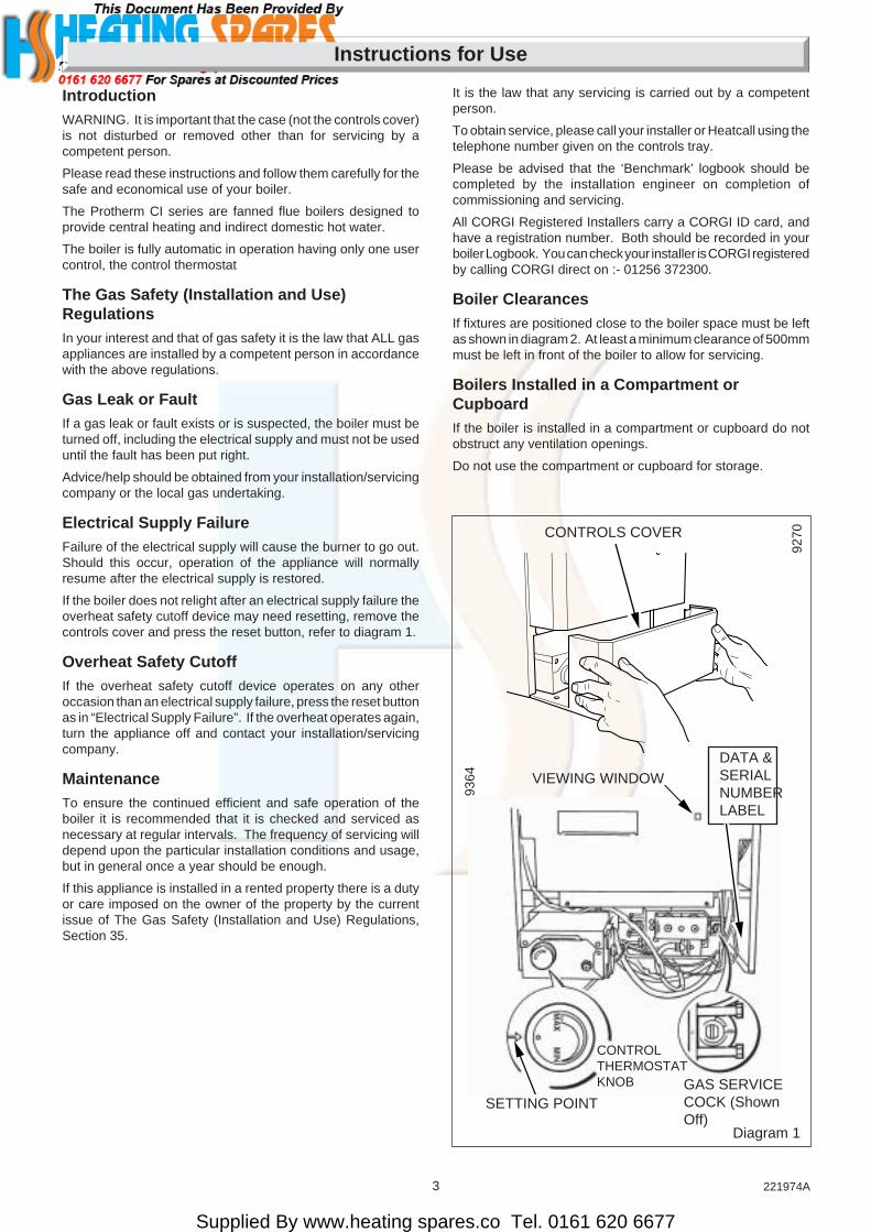
CONTROLS COVER
DATA &SERIALNUMBERLABEL
VIEWING WINDOW
SETTING POINT
CONTROLTHERMOSTATKNOB GAS SERVICE
COCK (ShownOff)
It is the law that any servicing is carried out by a competentperson.
To obtain service, please call your installer or Heatcall using thetelephone number given on the controls tray.
Please be advised that the ‘Benchmark’ logbook should becompleted by the installation engineer on completion ofcommissioning and servicing.
All CORGI Registered Installers carry a CORGI ID card, andhave a registration number. Both should be recorded in yourboiler Logbook. You can check your installer is CORGI registeredby calling CORGI direct on :- 01256 372300.
Boiler ClearancesIf fixtures are positioned close to the boiler space must be leftas shown in diagram 2. At least a minimum clearance of 500mmmust be left in front of the boiler to allow for servicing.
Boilers Installed in a Compartment orCupboardIf the boiler is installed in a compartment or cupboard do notobstruct any ventilation openings.
Do not use the compartment or cupboard for storage.
Instructions for Use
IntroductionWARNING. It is important that the case (not the controls cover)is not disturbed or removed other than for servicing by acompetent person.
Please read these instructions and follow them carefully for thesafe and economical use of your boiler.
The Protherm CI series are fanned flue boilers designed toprovide central heating and indirect domestic hot water.
The boiler is fully automatic in operation having only one usercontrol, the control thermostat
The Gas Safety (Installation and Use)RegulationsIn your interest and that of gas safety it is the law that ALL gasappliances are installed by a competent person in accordancewith the above regulations.
Gas Leak or FaultIf a gas leak or fault exists or is suspected, the boiler must beturned off, including the electrical supply and must not be useduntil the fault has been put right.
Advice/help should be obtained from your installation/servicingcompany or the local gas undertaking.
Electrical Supply FailureFailure of the electrical supply will cause the burner to go out.Should this occur, operation of the appliance will normallyresume after the electrical supply is restored.
If the boiler does not relight after an electrical supply failure theoverheat safety cutoff device may need resetting, remove thecontrols cover and press the reset button, refer to diagram 1.
Overheat Safety CutoffIf the overheat safety cutoff device operates on any otheroccasion than an electrical supply failure, press the reset buttonas in “Electrical Supply Failure”. If the overheat operates again,turn the appliance off and contact your installation/servicingcompany.
MaintenanceTo ensure the continued efficient and safe operation of theboiler it is recommended that it is checked and serviced asnecessary at regular intervals. The frequency of servicing willdepend upon the particular installation conditions and usage,but in general once a year should be enough.
If this appliance is installed in a rented property there is a dutyor care imposed on the owner of the property by the currentissue of The Gas Safety (Installation and Use) Regulations,Section 35.

Supplied By www.heating spares.co Tel. 0161 620 6677
4221974A
500mm FROM A PERMANENT FIXTURE
6mm 6mm
FRONT VIEW
6mm 6mm
6mm160mm
65mm
Diagram 2
CleaningWARNING. This appliance contains metal parts (components)and care should be taken when handling and cleaning, withparticular regard to edges.
Clean the casing occasionally by wiping it over with a dampcloth or dry polishing duster.
Do not use an abrasive cleaner.
Boiler Electrical SupplyWARNING. This boiler must be earthed.
The boiler must only be connected to a 230V~50Hz supplyprotected by a 3A fuse.
All wiring must be in accordance with the current issue ofBS7671.
Wiring to the boiler must be PVC insulated type to the currentissue of BS6500 Table 16, not less than 0.75mm2 (24/0.20mm).
The colours of three core flexible cable are:
Brown - live, Blue - neutral,
Green/yellow - earth.
As the markings on your plug may not correspond with thesecolours continue as follows:
The cable coloured blue must be connected to the terminalmarked “N” or black.
The cable coloured brown must be connected to the terminalmarked “L” or red.
The cable coloured green/yellow must be connected to theterminal marked “E”, or green or the earth symbol .
To Light the BoilerWARNING. Sealed Systems
A sealed water system must be filled and pressurised by acompetent person.
Only light the boiler when you are sure that the system has beenfilled and pressurised.
The pressure gauge should show at least 0.7bar, anything lessthan this figure could indicate a leak and you MUST contact yourinstallation/servicing company.
If there is any doubt about the boiler being full of water consultyour installation/servicing company.
ALL SYSTEMS.
Turn the electrical supply on to the boiler and check that allremote controls are calling for heat.
To Turn the Boiler OnOpen the controls cover door, by pulling it forward and down,see diagram 1.
Turn the control thermostat knob clockwise to any positionbetween MIN and MAX. The maximum temperature setting isabout 82oC (180oF), see diagram 1.
The boiler lighting operation is now automatic as follows.
The fan operates, followed by an ignition spark until the pilot islit. When the pilot is alight the ignition system switches off andthe main burner lights. The flames can be seen through theviewing window, see diagram 1.
The main burner will remain alight until switched off by thecontrol thermostat or any remote control.
If the boiler is switched OFF, by hand, wait at least 30 secondsbefore switching on again.
When the boiler switches off, both the pilot and main burner goout.
The automatic lighting sequence will operate again when heatis required.
Shut the controls cover.
It should be noted that this is a fan flue appliance and fanoperation may be heard.
To Turn the Boiler OffFor short periods, turn the control thermostat knob anti-clockwiseto “O” Off. To relight, turn the control thermostat knob to anyposition between “MIN” and “MAX”.
For longer periods, turn the control thermostat knob fully anti-clockwise to “O” Off and switch off the electrical supply to theboiler.
To relight follow the lighting sequence given above.
Protection Against Freezing.If the boiler is to be out of use for any long period of time duringsevere weather conditions we recommend that the whole of thesystem, including the boiler, be drained off to avoid the risk offreezing up. Make sure that, if fitted, the immersion heater in thecylinder is switched off.
For the position of the serial number, see diagram 1.
Instructions for Use
9271

Supplied By www.heating spares.co Tel. 0161 620 6677
5 221974A
CL
RE
TU
RN
PU
MP
ED
PU
MP
ED
FLO
W
CL
WATER CONNECTIONS22mm COPPER PIPE
GAS CONNECTIONSRC1/2 (1/2 in. BSPT)
SIDE ELEVATION FRONT ELEVATION
A
80
B
300
C
100
D
75
E
700
F
124
G
130
H
400
J
60
K
162
L
110
M
142
N
90
B
A
D
LK
N
J
G
F
E
M
C
R
H
1 General Data
Diagram 1.1
Important NoticeThis boiler is for use only on G20 gas.
This boiler can be used on open vented or sealed watersystems.
When used on an open vented system domestic hot water canonly be provided by a pumped primary circulation.
Wherever possible, all material, appliances and componentsused shall comply with requirements of applicable BritishStandards.
Where no British Standards exist, materials and equipmentshould be fit for their purpose and of suitable quality andworkmanship.
Sheet Metal PartsWARNING. When installing or servicing this boiler care shouldbe taken when handling sheet metal parts, to avoid any possibilityof personal injury.
1.1 Statutory RequirementsThe installation of the boiler must be carried out by a competentperson in accordance with the relevant requirements of thecurrent issue of:-
The manufacturer’s instructions, supplied.
The Gas Safety (Installation and Use) Regulations, The BuildingRegulations, Local Water Company Byelaws, The Health andSafety at Work Act, Control of Substances Hazardous toHealth, The Electricity at Work Regulations and any localregulations which may apply.
Detailed recommendations are contained in the current issue ofthe following British Standards and Codes of Practice:-
BS4814, BS6798, BS5440 Part 1 and 2, BS5546 Part 1,BS5449, BS6891, BS6700, BS7074 Part 1 and 2, BS7593,BS7671.
Manufacturer’s instructions must not be taken as overridingstatutory requirements
9273

Supplied By www.heating spares.co Tel. 0161 620 6677
6221974A
53 kg (117 lb)
47 kg (103lb)
3.35 litre (0.74 gallon)
Rc 1/2 in.
71WInternal fuse F1 & F2 (F1A)
2x22mm copper pipes fromtop of case
230V~50Hz, fused 3A
Bottom right hand side of case
1 General Data
TABLE 2.
RANGE RATING
APPROX. m3/hGASRATE ft3/h
Min. Medium Max.
2.1 2.4 2.7
74 86 97
DATA TABLE 1.
TOTAL DRYWEIGHT(IncludingTerminal)
LIFTWEIGHT
WATERCONTENT
GASCONNECTION
ELECTRICITYRATING
WATERCONNECTION
ELECTRICITYSUPPLY
DATA LABEL
BURNER INJECTOR MARKING: 205710BURNER INJECTOR SIZE: 4.0 mmPILOT INJECTOR MARKING: 7218
1.2 DataSee Table 1 and diagram 1.1.
All dimensions are given in millimetres (except as noted).
The Seasonal Efficiency Domestic Boilers UK (SEDBUK) is78.1%.
The value is used in the UK Government’s Standard AssessmentProcedure (SAP) for energy rating of dwellings. The test datafrom which it has been calculated have been certified by B.S.I.
1.3 Range RatingThis boiler is range rated and may be adjusted to suit individualsystem requirements.
See Table 2 and diagram 1.3 for ratings and settings.
1.4 B.S.I. CertificationThis boiler is certificated to the current issue of British Standard6332 Part 1, invoking the current issue of BS5258 Part 1 forperformance and safety. It is, therefore, important that noalteration is made to this boiler without permission, in writing,from Hepworth Heating Ltd.
Any alteration that is not approved by Hepworth Heating Ltd.,could invalidate the B.S.I. Certification of the boiler, warrantyand could infringe the current issue of the StatutoryRequirements.
1.5 Gas SupplyThe gas installation shall be in accordance with the currentissue of BS6891.
The supply from the governed meter must be of adequate sizeto provide a steady inlet working pressure of 20mbar (8in wg) atthe boiler.
On completion test the gas installation for soundness using thepressure drop method and suitable leak detection fluid, purgein accordance with the above standard.
1.6 Electrical SupplyWARNING. This boiler must be earthed.
All system components shall be of an approved type and shallbe connected in accordance with the current issue of BS7671and any applicable local regulations.
Connection of the boiler and system controls to the mainssupply must be through a common isolator and must be fused3A, maximum. This method of connection must be by a fuseddouble pole isolating switch, with a minimum contact separationof 3mm on both poles. The switch should be readily accessibleand preferably adjacent to the appliance. It should supply theappliance only and be easily identifiable as so doing.
Alternatively, an unswitched shuttered socket outlet and 3Afused 3 pin plug, both to the current issue of BS1363 may beused provided that they are not used in a room containing a bathor shower.
Wiring to the boiler must be to the current issue of BS6500 Table16, not less than 0.75mm2 (24/0.20mm).
1.7 Contents of PackagingThe boiler is delivered in one pack, refer to Section 4.1 forcontents.
1.8 Water SystemThis boiler may be fitted to an open vented or a sealed watersystem.
TABLE 3. COMPARTMENT AIR VENTS
VENTILATION HIGH LEVEL LOW LEVELREQUIREMENTS VENT AREA VENT AREA
VENTILATIONFROM ROOMOR SPACE
VENTILATIONFROMOUTSIDE
cm2 in2 cm2 in2
264 41 264 41
132 21 132 21
1.9 DrainSystem
A drain tap must be provided at the lowest points of the systemwhich will allow the entire system, boiler and hot water cylinderbe drained.
Draining taps should be to the current issue of BS2879.
Boiler
A draining point is fitted at the bottom right hand side of the heatexchanger.
Cover controls to avoid water damage.
If required remove the combustion chamber front cover toimprove access.

Supplied By www.heating spares.co Tel. 0161 620 6677
7 221974A
Diagram 1.2
500mm FROM A PERMANENT FIXTURE
6mm 6mm
FRONT VIEW
6mm 6mm
6mm160mm
65mm
1 General Data
1.10 Safety ValveA safety valve need not be fitted to an open vented system.
1.11 LocationThis boiler is not suitable for outdoor installation.
This boiler may be installed in any room, although particularattention is drawn to the requirements of the current issue ofBS7671 with respect to the installation of a boiler in a roomcontaining a bath or shower. The electrical provisions of theBuilding Standards (Scotland) apply to such installations inScotland.
The boiler must be mounted on a flat wall which is sufficientlyrobust to take its total weight.
The boiler may be fitted to a wall made of combustible material.
1.12 Boiler ClearancesRefer to diagram 1.2.
This boiler must be positioned so that at least the minimumoperational and servicing clearances are provided.
Additional clearances may be required for installation.
If fixtures are positioned next to the boiler they should be maderemovable for access to pipework.
At least a minimum of 500mm clearance must be left in front ofthe boiler for servicing, see diagram 1.2.
1.13 Room VentilationThe boiler is room sealed and does not require the room orspace containing it to have permanent air vents.
1.14 Boilers in a CompartmentWhere the installation of the boiler will be in an unusual position,special requirements are needed, the current issue of BS6798gives detailed guidance on these requirements.
A compartment used to enclose the boiler must be designedand constructed specifically for this purpose. An existingcupboard or compartment modified for the purpose may beused. Details of essential requirements for cupboard orcompartment design are given in the current issue of BS6798.
The doorway opening should be of sufficient size to allow foreasy removal of the boiler.
Where the boiler is fitted in a cupboard or compartment,permanent high and low level ventilation must be provided. Theminimum ventilation areas required are given in Table 3.
1.15 Timber Frame BuildingIf the boiler is to be installed in a timber frame building it shouldbe fitted in accordance with the Institute of Gas Engineersdocument IGE/UP/7/1998. If in doubt seek advice from the localgas undertaking or Hepworth Heating Ltd.
1.16 Heating System ControlsThe heating system should have installed: a programmer androom thermostat controlling the boiler.
Thermostatic radiator valves may be installed, however theymust not be fitted in a room where the room thermostat islocated.
Note: For further information, see The Building Regulations1991 - Conservation of fuel and power, 1995 edition - AppendixG, table 4b.
MINIMUM CLEARANCES FROM WALLSCEILING, FLOOR, CUPBOARD, WORKTOPS,AND INFLAMMABLE MATERIALS
9271
Diagram 1.3
9804

Supplied By www.heating spares.co Tel. 0161 620 6677
8221974A
2 Flue and Ventilation
A
A
FG E
A
G
G
G
B,C B,C
F FK
K
K
C
G
L L
Diagram 2.1
MINIMUM SITING DIMENSIONS FOR FANNED FLUE TERMINALS POSITION
A DIRECTLY BELOW, ABOVE ORHORIZONTALLY TO AN OPENING,
AIR BRICK, OPENING WINDOWS,AIR VENT OR ANY OTHERVENTILATION OPENING. 300
B BELOW GUTTER, DRAIN/SOIL PIPE 75
C BELOW EAVES 200
D BELOW A BALCONY OR CAR PORT 200
E FROM VERTICAL DRAIN PIPES ANDSOIL PIPES 75
F FROM EXTERNAL CORNERS 300
G ABOVE ADJACENT GROUND ORBALCONY LEVEL 300
H FROM A SURFACE FACING THETERMINAL 600
I FACING TERMINALS 1200
J FROM OPENING (DOOR/WINDOW) INCAR PORT INTO DWELLING 1200
K VERTICAL FROM A TERMINAL 1500
L HORIZONTALLY FROM A TERMINAL 300
M FROM INTERNAL CORNERS 25
MINIMUMSPACING
in mm
0103
M
Under Car Port etc.
H,I
JD
FK
M
Note. Detailed recommendations for flue are given in thecurrent issue of BS5440 Part 1.
2.1 Terminal PositionThe minimum acceptable siting dimensions for the terminalfrom obstructions, other terminals and ventilation openings areshown in diagram 2.1.
The terminal must be exposed to the external air, the positionallowing free passage of air across it at all times.
Car ports or similar extensions of a roof only, or a roof and onewall, require special consideration with respect to any openings,doors, vents or windows under the roof. Care is required toprotect the roof if it is made of plastic sheeting. If the car portconsists of a roof and two or more walls, seek advice from thelocal gas company before installing the boiler.
If the terminal is fitted within 600mm below plastic guttering orpainted soffit an aluminium shield 1500mm long should be fittedimmediately beneath the guttering or eaves. If the terminal isfitted within 450mm below painted eaves or a painted gutter, analuminium shield 750mm long should be fitted immediatelybeneath the guttering or eaves.
2.2 Terminal GuardA terminal guard is required if persons could come into contactwith the terminal or the terminal could be subject to damage.
If a terminal guard is required, it must be positioned to providea minimum of 50mm clearance from any part of the terminal andbe central over the terminal.
A suitable guard, reference Type “K3”, can be obtained from:
Tower Flue Components LtdMorley RoadTonbridgeKentTN9 1RA
2.3 Flue OptionsStandard Top Outlet Flue Pack - Pt. No. 230483, supplied withboiler.
1 Metre Extension Kit - Pt. No. 230484.A flue system up to 3 metres in length can be made byconnecting 1 metre extension kits together.
Optional Wall Liner Kit - Pt. No. 900862.
45° Flue Bend Pack - Pt. No. 230485.
90° Flue Bend Pack - Pt. No. 230486.
Vertical Flue Kit - Pt. No. 458115.
2.4 Vertical Balanced Flue SystemIMPORTANT NOTE : See Section 4.8 Easi-Vent Vertical FlueTerminal, for Installation requirements and fitting instructions.
0161
M

Supplied By www.heating spares.co Tel. 0161 620 6677
9 221974A
1000
750
500
250
0
0 5 10 15 20 25 30
Flow rate (litres/minute)
Wat
er p
ress
ure
loss
(mm
hea
d of
wat
er)
9154
Design Flow Rate
30.6L /min
Diagram 3.1
3 Water Systems
The installation of the boiler must comply with the requirementsof the current issue of BS6798.
3.1 Frost ProtectionIf the position of the boiler is such that it may be vulnerable tofreezing it should be protected as specified in the current issueof BS5422. It is recommended that a frost protection thermostatbe fitted.
3.2 PumpThe pump, with integral valves, should be fitted in the heatingflow pipework from the boiler, it should be set to produce atemperature difference of 11oC (20oF) between the flow andreturn, with the boiler thermostat set at “MAX”, which is about82oC (180oF).
The pressure loss of the boiler can be found from diagram 3.1.
High resistance microbore systems may require a higher dutypump.
3.3 Bypass - Fully Pumped and Sealed WaterSystemA bypass is usually unnecessary on systems using a 3 portdiverter valve since one port will remain in the open position atall times. This allows satisfactory operation of the pumpoverrun.
However if thermostatic radiator valves are fitted to all radiatorsor two port valves are used a bypass is required.
The bypass connection must be at least 2.5 metres away fromthe boiler.
The flow through the boiler must not be allowed to fall such thatthere is a temperature difference greater than 20oC between theflow and return.
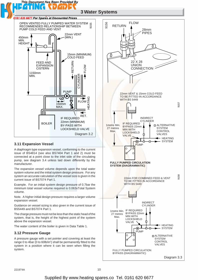
3.4 Water SystemFor an open vented system the boiler must be supplied from anunrestricted water supply taken from a feed and expansioncistern fitted at a maximum height of 27metres above the boiler.
The cold feed must be 15mm minimum size.
It is important that the relative positions of the pump, cold feedand open vent are as shown in diagram 3.2.
The unrestricted open vent from the boiler must rise continuouslyto discharge over the feed and expansion cistern.
3.5 Domestic Hot Water SystemGeneral. The domestic hot water service must be in accordancewith the current issue of BS5546, refer also to the current issueof BS6700.
3.6 CylinderFor all systems supplying domestic hot water the cylinder mustbe indirect. It is recommended that the cylinder be fitted withsome form of temperature control.
3.7 Fully Pumped Domestic Hot WaterThe connection for this type of system MUST be as shown indiagram 3.2 and 3.3.
3.8 InhibitorAttention is drawn to the current issue of BS5449 and BS7593on the use of inhibitors in central heating systems.
If an inhibitor is to be used, contact a manufacturer or HepworthHeating Ltd., for their recommendations as to the best productto use.
When installing in an existing system take special care to drainthe entire system, including radiators, then thoroughly cleaningout before installing the boiler whether or not adding an inhibitor.
3.9 Sealed Water SystemsThe installation should comply with the appropriate requirementsof the current issue of BS4841, BS5449, BS6759, BS6798 andBS7074 Part 1 and 2, see diagram 3.4 for suggested layout.
3.10 Safety ValveA safety valve must be fitted to a sealed water system.
It shall be preset, nonadjustable with a lift pressure of 3bar,incorporating seating of a resilient material, a test device and aconnection for drain.
The drain from the safety valve must be routed clear of anyelectrical fittings and positioned so that any discharge can beseen.
PRESSURE LOSSFF BOILER
Supplied By www.heating spares.co Tel. 0161 620 6677
10221974A
3 Water Systems
Diagram 3.2
9155
FEED ANDEXPANSIONCISTERN
22mm VENT(MIN.)
15mm (MINIMUM)COLD FEED
OPEN VENTED FULLY PUMPED WATER SYSTEMRECOMMENDED RELATIONSHIP BETWEENPUMP COLD FEED AND VENT
450mmMIN.HEIGHT
1150mmMIN.
RE
TU
RN
FLO
W
CY
LIN
DE
R
PUMPH
EA
TIN
G
150mmMAX.
BOILER
IF REQUIRED22mm (MINIMUM)BY-PASS WITHLOCKSHIELD VALVE
FLOW
RET.
Diagram 3.3
1metre Min.27 metres
Max.
22mm VENT & 15mm COLD FEEDTO BE FITTED IN ACCORDANCEWITH BS 5449
INDIRECTCYLINDER
ALTERNATIVESYSTEMCONTROLVALVES
HEATINGSYSTEM
PUMP
FULLY PUMPED CIRCULATIONSYSTEM (DIAGRAMMATIC)
9157
IF REQUIREDBYPASS 22mmMIN WITHLOCKSHIELDVALVE
28mmPIPES
RETURNFLOW
9156
1metre Min.27 metres
Max.
22mm FOR COMBINED FEED & VENTTO BE FITTED IN ACCORDANCE WITH BS 5449
INDIRECTCYLINDER
ALTERNATIVESYSTEMCONTROLVALVES
HEATINGSYSTEM
PUMP
FULLY PUMPED CIRCULATIONBYPASS (DIAGRAMMATIC)
9158
IF REQUIREDBYPASS 22mmMIN WITH LOCKSHIELDVALVE
3.11 Expansion VesselA diaphragm type expansion vessel, conforming to the currentissue of BS4814 (see also BS7404 Part 1 and 2) must beconnected at a point close to the inlet side of the circulatingpump, see diagram 3.4 unless laid down differently by themanufacturer.
The expansion vessel volume depends upon the total watersystem volume and the initial system design pressure. For anysystem an accurate calculation of the vessel size is given in thecurrent issue of BS7074 Part 1.
Example. For an initial system design pressure of 0.7bar theminimum total vessel volume required is 0.063xTotal Systemvolume.
Note. A higher initial design pressure requires a larger volumeexpansion vessel.
Guidance on vessel sizing is also given in the current issue ofBS5449 and BS7074 Part 1.
The charge pressure must not be less than the static head of thesystem, that is, the height of the highest point of the systemabove the expansion vessel.
The water content of the boiler is given in Data Table 1.
3.12 Pressure GaugeA pressure gauge with a set pointer and covering at least therange 0 to 4bar (0 to 60lb/in2) shall be permanently fitted to thesystem in a position where it can be seen when filling thesystem.
22 X 28UNIONCONNECTION

Supplied By www.heating spares.co Tel. 0161 620 6677
11 221974A
METHOD 1
METHOD 2
METHOD 3
SUPPLY STOPVALVESUPPLY
PIPE
HOSEUNIONS
SERVICINGVALVE
TEMPORARYHOSE
HEATINGSYSTEM
HEATINGSYSTEMTEMPORARY
HOSE
HOSEUNIONS
SERVICINGVALVE
SUPPLYPIPE
SUPPLY STOPVALVE
DOUBLE CHECKVALVE ASSEMBLY
HEATINGSYSTEMSERVICING
VALVE
SUPPLYSTOP VALVE
SUPPLYPIPE
HOSEUNIONS DOUBLE CHECK
VALVE ASSEMBLY
OVERFLOWCISTERN
COMBINEDCHECK VALVEAND VACUUMBREAKER
PRESSUREREDUCINGVALVE
0051M
Diagram 3.4
3 LITRES (0.66 gals)MAKE-UP BOTTLE(if required)
NON-RETURNVALVE
AUTOAIRVENT
FLOW
DRAINCOCK
BOILER
SAFETYVALVE
(Make-upalternatives) EXPANSION
VESSEL
PRESSUREGAUGE
CIRCULATINGPUMP
FILLING POINT
AIRRELEASEPOINT
HE
AT
ING
CIR
CU
IT
IF REQUIRED22mm (min)BY-PASS WITHLOCKSHIELD VALVE
RETURN
9159
3 Water Systems
Diagram 3.5
3.13 Domestic Hot Water CylinderSINGLE FEED INDIRECT CYLINDERS ARE NOT SUITABLE.
The domestic hot water cylinder must be of the indirect coil type.It must be suitable for working at a gauge pressure of 0.35barabove the safety valve setting.
3.14 Domestic Hot Water System - UnventedWhere a storage system will not have a vent to atmosphere theinstallation must comply with Building Regulations and localWater Company Bye-laws, see also the current issue of BS6700.
If fitting into an existing system the local authority must also beadvised.
3.15 Filling a Sealed Water SystemProvision for filling the system at low level must be made. Threemethods are shown in diagram 3.5. There must be no permanentconnection to the mains water supply, even through a non-return valve.
3.16 Water MakeupProvision must be made for replacing water lost from thesystem. A make up vessel mounted above the highest point ofthe system and connected through a non-return valve to thesystem on the return side of either the hot water cylinder orheating system, see diagram 3.4.
Alternatively provision for make up can be made by a filling loop.

Supplied By www.heating spares.co Tel. 0161 620 6677
12221974A
Diagram 4.1
4 Flue and Appliance Preparation
REAR FLUESIDE FLUE
15mm
Note: Outer casing, mounting brackets & boiler details removed for clarity
Note: 1 metre extension kits can be joined together, but the total flue system must not exceed 3 metres.
Note: Outer casing, mounting brackets & boiler details removed for clarity
SCREW & TAPE
9370
FLUE LENGTHMAX 570mm (std)
FLUE LENGTHMAX 570mm (std)
15mm
SCREW & TAPE
STANDARD FLUE PACK
'X'
SIDE FLUE
SCREW & TAPE
STANDARD FLUE PACK & 1 METRE EXTENSION KIT
FLUE LENGTHTotal must not excede 3m MAX.
15mm
SCREW & TAPE
'X'
'Y'
31mm
STANDARDREARSIDE R.H.SIDE L.H.
MINIMUMWALL
THICKNESS
MINIMUMFLUE
LENGTH
MAXIMUMFLUE
LENGTH
"Y"BOILER MOUNTING FACETO EXTERNAL WALL FACE
"X"BOILER CASING TO
EXTERNAL WALL FACE
MAXIMUM DISTANCE FROM
12893273
527 - -
- 555 372
757575
570570570
--
- -
2988 2808
7575
30003000
FLUEPACKS
NOTE : FLUE & AIR DUCT CUTTINGTHE DUCTS WILL REQUIRE CUTTING FOR FLUE LENGTHS LESS THAN 280mm.THE DUCTS CAN BE CUT FLUSH BUT MUST HAVE AN OVERLAP OF 50mm.
STANDARD
SIDE R.H.SIDE L.H.
PLUS 1 METREEXTENSION KITS

Supplied By www.heating spares.co Tel. 0161 620 6677
13 221974A
NOTE : Make sure that the ductings do not slope down towardsthe boiler.
4.1 Flue Position and LengthDetermine flue application, length and terminal position beforestarting.
Refer to diagram 4.1.
4.2 Flue PreparationAll flue assemblies are designed for internal installation, giventhat there is sufficient clearances opposite to the flue for theinstallation of the flue.
If there is insufficient clearance the flue can be installed fromoutside.
For a wall thickness of over 300mm the external flue hole willneed to be made good from the outside.
4.3 Top and Side Flue ApplicationSelect the boiler location and flue application, with due regardto the terminal position, see diagram 2.1.
Take the template from the boiler pack and temporarily positionit on the wall, making sure that the minimum clearances aremaintained, see diagram 4.2.
Mark the centre line position of the flue, as diagram 4.2.
For a side flue, extend centre line of flue to L.H. or R.H. corner.Mark the position of the centre of the flue and boiler, asdiagram 4.2.
4.4 Flue Hole CuttingHaving marked out the flue centre cut a hole for the flue using,preferably, a 115mm minimum core drill.
4.5 Wall Mounting BracketReposition the template, making sure of dimensional alignmentwith the flue hole.
Mark the boiler fixing points and mounting bracket position, seediagram 4.3.
Drill holes and plug, to suit No. 12x2in wood screws, fit thescrews allowing sufficient clearance, about 5mm, to allow boilerto be hung.
Secure the mounting bracket to the wall with two No.12x2inwood screws and plugs, see diagram 4.3.
4.6 Flue DuctExtend the telescopic flue to the required length, making surethat the minimum overlap is no less than 25mm, and that the flueterminal projects 15mm minmum beyond wall face, see diagram4.1.
Carefully drill though air duct pilot hole and secure with selftapping screw provided in fittings pack, see diagram 4.1.
Seal the joint with the tape provided.
If the boiler is not to be fitted for some time cover the hole in thewall.
4.7 Top, Side Flue FixingMake sure that the ductings do not slope down towards theboiler.
Make good the area around the flue inside and outside afterinstallation of the boiler.
4 Flue and Appliance Preparation
SIDE FLUE
145mm
115mmMINIMUMHOLE
BOILERCENTRE LINE
FLUECENTRE LINE
90mm
TOP BOILERMOUNTINGPOINT
BOTTOM BRACKETMOUNTING POINT
Diagram 4.2
9288
Diagram 4.3
9210
FLUECENTRE LINE
BOILERMOUNTINGBRACKET
BOILERCENTRE LINE
5mm

Supplied By www.heating spares.co Tel. 0161 620 6677
14221974A
4 Flue and Appliance Preparation
4.8 Easi-Vent Vertical Flue Terminal
GeneralThe kits shown in diagram 4.4, enable the Protherm to be fittedwith the flue configurations shown in diagram 4.6.
For other accessories, see diagram 4.5.
Only proprietary parts supplied by Hepworth Heating Ltd.should be used.
4.9 Accessories
Ceiling Collar - Part No. 208590Used if required as a ceiling trim immediately below the ceilingto make a neat installation.
Fixings are required to hold ceiling collar in position.
FITTINGS PACK
AIR DUCT
FLUE DUCT
FITTINGSPACK
TOP FLUE TRANSITION DUCT
TERMINAL ASSEMBLY
AIR/FLUEDUCT ASSEMBLY
FLUE SPIGOT
EASI-VENT ADAPTORRING
TAPE (FITTINGSPACK SUPPLIEDWITH BOILER)
4 SCREWS(FITTINGS PACKSUPPLIED WITHBOILER)
45o FLUE BEND KIT Pt No. 230485
VERTICAL FLUE PACK Pt No. 458115
1M EXTENSION KIT Pt No. 230484
7527
90o FLUE BEND KIT Pt No. 230486
75297528
FITTINGS PACK
FITTINGS PACK
(DISCARD)
Diagram 4.4
Support Assembly - Part No. 208591Manufactured in galvanised steel and incorporates a fire stopplate with fitted spacer lugs and support collar. This item shouldbe used to support the flue at the top of each floor joist andprovide a fire stop feature. Spacer lugs fitted to the undersideof the plate ensures that a clearance is maintained between theinner liner of the flue and any combustible materials. Thesupport collar which is situated on the top of the plate should besecurely fixed around the flue by tightening the nut and boltfasteners provided. The plate should be nailed or screwed tothe ceiling joists.
Fire Stop Plate - Part No. 208592Manufactured in galvanised steel and fitted with spacer lugswhich ensure that a clearance is maintained between the innerliner of the flue and any combustible materials. The fire stopplate should be fitted to the underside of the ceiling joists bysliding over the flue and nailed or screwed to the joists. Thisitem can act as a dust plate and should be used when the fluesystem passes through non combustible floors such as concrete.

Supplied By www.heating spares.co Tel. 0161 620 6677
15 221974A
4 Flue and Appliance Preparation
FIRESTOP PLATE(Pt.No.208592)
ADJUSTABLE WALL BAND(Pt.No.208594)
CEILING COLLAR(Pt.No.208590)
CEILING PLATE(Pt.No.208593)
SUPPORT ASSEMBLY(Pt.No.208591)
7122
Diagram 4.5
Ceiling Plate - Two Piece - Part No. 208593Manufactured in galvanised steel and should be used on theunderside of floor joists where the flue passes through the flooror roof in a non vertical plane. This item is supplied withoutspacer lugs and should be nailed or screwed to the undersideof the joists.
Adjustable Wall Band - Part No. 208594The wall bracket is supplied in two parts - an aluminium bandwhich fits tightly around the outside of the flue and a galvanised“T” bracket which is secured to a wall or batten. This item is usedwhere the flue is positioned up to 280mm from a wall or point.
4.10 Flue Terminal Position
CautionIf the flue is to pass through or near combustible material itshould be fitted in accordance with the current issue of BS5440Part 1, which requires a minimum clearance of 25mm from theflue duct.
The minimum clearance from the air duct is 5mm.
The terminal should be positioned so as to cause the leastproblem with the dispersal of the products of combustion andany “pluming” that can occur.
If the terminal is fitted less than 500mm below plastic gutters orless than 500mm below painted eaves or any other paintedsurface then an aluminium shield at least 1metre long should befitted immediately beneath the guttering or eaves.
Minimum distances for flue to walls and roof positions areshown in diagram 4.6.
Failure to comply with these instructions could result in apotentially dangerous installation and loss of boiler efficiency.
General guidance only can be found in the current issue ofBS5440 Part 1.
If in doubt consult Heatcall.
��yy
��yy ��yy
�y
PITCHED ROOF WITH STRUCTURE
5712
Diagram 4.6
300mm
350mm
MINIMUM DIMENSIONS
FLAT ROOF INTERNAL CORNER
400mm
300mm
300mm
Supplied By www.heating spares.co Tel. 0161 620 6677
16221974A
4 Flue and Appliance Preparation
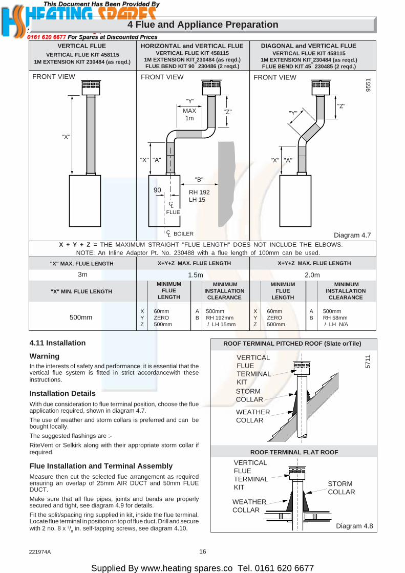
4.11 Installation
WarningIn the interests of safety and performance, it is essential that thevertical flue system is fitted in strict accordancewith theseinstructions.
Installation DetailsWith due consideration to flue terminal position, choose the flueapplication required, shown in diagram 4.7.
The use of weather and storm collars is preferred and can bebought locally.
The suggested flashings are :-
RiteVent or Selkirk along with their appropriate storm collar ifrequired.
Flue Installation and Terminal AssemblyMeasure then cut the selected flue arrangement as requiredensuring an overlap of 25mm AIR DUCT and 50mm FLUEDUCT.
Make sure that all flue pipes, joints and bends are properlysecured and tight, see diagram 4.9 for details.
Fit the split/spacing ring supplied in kit, inside the flue terminal.Locate flue terminal in position on top of flue duct. Drill and securewith 2 no. 8 x 3/8 in. self-tapping screws, see diagram 4.10.
ROOF TERMINAL PITCHED ROOF (Slate orTile)
ROOF TERMINAL FLAT ROOF
5711VERTICAL
FLUETERMINALKIT
VERTICALFLUETERMINALKIT
WEATHERCOLLAR
WEATHERCOLLAR
Diagram 4.8
STORMCOLLAR
STORMCOLLAR
3m
VERTICAL FLUE KIT 458115
"X" MAX. FLUE LENGTH
X + Y + Z = THE MAXIMUM STRAIGHT "FLUE LENGTH" DOES NOT INCLUDE THE ELBOWS.
Diagram 4.7
"X"
HORIZONTAL and VERTICAL FLUEVERTICAL FLUE KIT 458115
1M EXTENSION KIT 230484 (as reqd.)FLUE BEND KIT 90° 230486 (2 reqd.)
"X"
CLFLUE
LC BOILER
"Z"MAX1m
"Y"
DIAGONAL and VERTICAL FLUE
90
X+Y+Z MAX. FLUE LENGTH X+Y+Z MAX. FLUE LENGTH
1.5m 2.0m
VERTICAL FLUE KIT 4581151M EXTENSION KIT 230484 (as reqd.)FLUE BEND KIT 45° 230485 (2 reqd.)
"X"
"Z"
"X" MIN. FLUE LENGTHMINIMUM
FLUELENGTH
500mmX 60mm A 500mmY ZERO B RH 192mmZ 500mm / LH 15mm
FRONT VIEWFRONT VIEW FRONT VIEW
1M EXTENSION KIT 230484 (as reqd.)
MINIMUMINSTALLATIONCLEARANCE
X 60mm A 500mmY ZERO B RH 58mmZ 500mm / LH N/A
VERTICAL FLUE
9551
NOTE: An Inline Adaptor Pt. No. 230488 with a flue length of 100mm can be used.
MINIMUMINSTALLATIONCLEARANCE
MINIMUMFLUE
LENGTH
"B"
"A" "A"
"Y"
RH 192LH 15

Supplied By www.heating spares.co Tel. 0161 620 6677
17 221974A
4 Flue and Appliance Preparation
STEP 1
STEP 2
STEP 4STEP 3
Diagram 4.9
Push flue duct & air ductinto flue spigot and lock intoposition by turning clockwise.
STEP 6
STEP 5Slide flue duct & air ducttogether, mark, drill, screwand seal with tapeprovided.
Push flue bend (45o or 90o)onto flue duct or boiler endstandard flue, drill and screwthen seal with tape provided.
Push flue duct & air ductonto flue bend (45o or 90o),drill and screw then sealwith tape provided.
Push flue bend (45o or 90o)onto flue duct & air duct, drilland screw then seal with tapeprovided.
FLUE BEND(90˚ or 45˚)
SECURINGSCREW (2)
SECURINGSCREW (2)
Push flue duct& air ductonto flue bend(45o or 90o),drill and screwthen seal withtape provided.SECURING
SCREW (2)
FLUE BEND(90˚ or 45˚)
SECURINGSCREW (4)
AIR/FLUE DUCTASSEMBLY
7382
FLUE DUCT SPIGOTSecure to boiler with screws providedin the boiler fittings pack.
No. 8 x 3/8 in.
3mm
TOP FLUETRANSITION DUCT(DISCARD)
Diagram 4.10
FLUEDUCTNo. 8 x 3/
8 in.
3mm
AIRDUCT
TERMINAL
EASI-VENTADAPTORRING
7390
4416
Pitched and Flat RoofFit Weather and Storm Collar onto air duct/terminal assembly,see diagram 4.8.
Make sure the weather collar is correctly positioned and sealedfor the roof type.
Fit the flue adaptor into flue terminal and connect to air duct.
After the flue terminal is fitted, fit an appropiate wall band.
Make sure that a weather proof seal is made in accordance withgood building practice.

Supplied By www.heating spares.co Tel. 0161 620 6677
18221974A
5 Boiler Installation
Diagram 5.1
CONTROLSCOVER
FRONTCOVER
SHAKEPROOFWASHER
9202
NUT
5.1 Boiler PreparationOpen the carton, check the items supplied against the boilerpack contents list on the carton flap.
With the boiler still in in the bottom tray slide the controls coverupwards and remove, see diagram 5.1.
Remove the front cover by undoing the wing nut, nut andwasher, lift the front cover off, see diagram 5.1.
Place controls cover and front cover to one side until required.
Fit suitable compression fittings to the required tappings on theboiler.
Disconnect the air pressure tubes, see diagram 8.1.
Remove the blue and red electrical connections from the fan,see diagram 8.1.
Remove the front right hand flue hood securing screw andslacken off the front left hand one, see diagram 8.3.
Remove fan and flue hood assembly from boiler by drawingassembly forward, place to one side until required.
5.2 Mounting the boilerLift the boiler into position ensuring first that the bottom of theboiler is hooked on to the boiler mounting bracket and thenengage the two keyhole slots, located on top of the boiler, on tothe securing screws. Tighten the two securing screws, seediagram 5.2
Note: Installations where the flue exits to the left of the boiler,complete the water connections to the boiler before fitting theflue.
From the fittings pack, place top turret gasket in position onboiler flue opening, see diagram 5.3
Taking care not to damage the gasket, secure the top turret withflue assembly to the boiler with four self-tap screws, seediagram 5.3.
From the fittings pack, fit flue duct extension assembly into thetop turret flue ducting and loosely fit jubilee clip on elbow of theflue duct extension, see diagram 5.4.
Refit fan and flue hood assembly, ensuring that the flue hood fitsin the flue hood retaining clamps and engage the fan into theelbow of flue duct extension, see diagram 8.3
Tighten up left hand flue hood securing screw, replace the righthand one and tighten, see diagram 8.3.
Secure fan to elbow of flue duct extension by tightening upjubilee clip, see diagram 5.4.
WINGNUT
9270

Supplied By www.heating spares.co Tel. 0161 620 6677
19 221974A
5 Boiler Installation
Diagram 5.2
SECURINGSCREWS (2)
5.3 Water Circulation SystemComplete the water connections to the boiler.
Fill, vent and flush the system.
Check for any water leaks and put right.
5.4 Safety Valve DischargeFit a suitable discharge pipe to the safety valve and route it tooutside the building so that any discharge can be seen but willnot cause injury to persons, damage to property or any electricalinstallation.
5.5 Gas ConnectionMake the gas connection to the Rc1/2in gas service cock, seediagram 6.1.
Check for leaks using a suitable leak detection fluid.
5.6 Control Box RemovalRemove the electrical control box securing screws, see diagram5.5. Slide the box forwards and release, hook it onto the lipbracket at the front, see diagram 5.5.
Diagram 5.4
TOP TURRETFLUE DUCTING 91
39
Diagram 5.3
TOPTURRET
9203
GASKET
SCREWS(4)
TOP TURRET FLUE OUTLET
FLUEDUCTEXTENSION
FLUE DUCTEXTENSION
5mm
BOILERMOUNTINGBRACKET
9283
JUBILEECLIP
Supplied By www.heating spares.co Tel. 0161 620 6677
20221974A
Diagram 5.6
3310
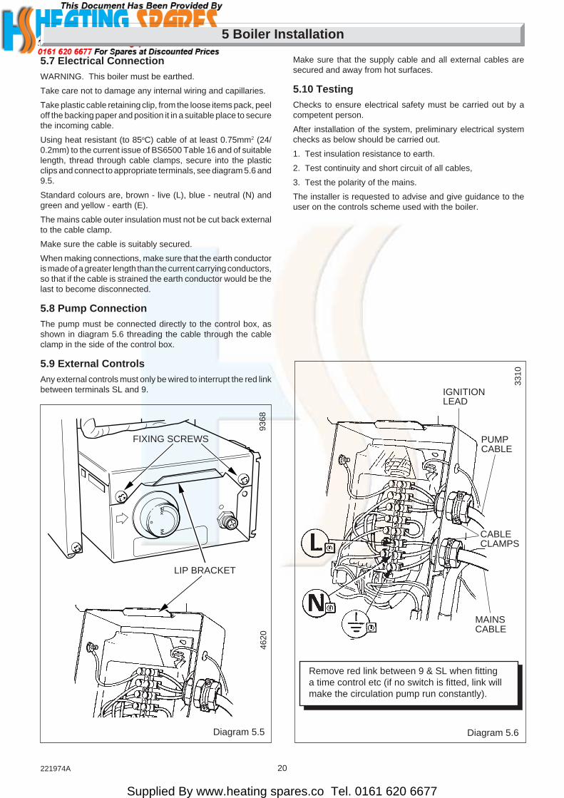
Make sure that the supply cable and all external cables aresecured and away from hot surfaces.
5.10 TestingChecks to ensure electrical safety must be carried out by acompetent person.
After installation of the system, preliminary electrical systemchecks as below should be carried out.
1. Test insulation resistance to earth.
2. Test continuity and short circuit of all cables,
3. Test the polarity of the mains.
The installer is requested to advise and give guidance to theuser on the controls scheme used with the boiler.
Remove red link between 9 & SL when fittinga time control etc (if no switch is fitted, link willmake the circulation pump run constantly).
IGNITIONLEAD
PUMPCABLE
CABLECLAMPS
MAINSCABLE
5 Boiler Installation
5.7 Electrical ConnectionWARNING. This boiler must be earthed.
Take care not to damage any internal wiring and capillaries.
Take plastic cable retaining clip, from the loose items pack, peeloff the backing paper and position it in a suitable place to securethe incoming cable.
Using heat resistant (to 85oC) cable of at least 0.75mm2 (24/0.2mm) to the current issue of BS6500 Table 16 and of suitablelength, thread through cable clamps, secure into the plasticclips and connect to appropriate terminals, see diagram 5.6 and9.5.
Standard colours are, brown - live (L), blue - neutral (N) andgreen and yellow - earth (E).
The mains cable outer insulation must not be cut back externalto the cable clamp.
Make sure the cable is suitably secured.
When making connections, make sure that the earth conductoris made of a greater length than the current carrying conductors,so that if the cable is strained the earth conductor would be thelast to become disconnected.
5.8 Pump ConnectionThe pump must be connected directly to the control box, asshown in diagram 5.6 threading the cable through the cableclamp in the side of the control box.
5.9 External ControlsAny external controls must only be wired to interrupt the red linkbetween terminals SL and 9.
9368
FIXING SCREWS
LIP BRACKET
4620
Diagram 5.5

Supplied By www.heating spares.co Tel. 0161 620 6677
21 221974A
6 Commissioning
Diagram 6.2
9364
4108
Diagram 6.1
Please ensure the “Benchmark” logbook is completed and leftwith the user.
6.1 All SystemsCommissioning should be carried out by a competent person inaccordance with the current issue of BS6798.
Make sure that the system has been thoroughly flushed out withcold water without the pump in place.
Refit the pump, fill the system with water, making sure that allair is properly vented from the system and pump.
Before operating the boiler check that all external controls arecalling for heat.
6.2 Sealed Water Systems OnlyFlush the whole of the system with cold water without the pumpin place. Refit the pump and fill until the pressure gaugeregisters 2.7bar (40lbf/in2). Clear any air locks and check forwater soundness.
Check the operation of the safety valve, by allowing the waterpressure to rise until the valve opens. The valve should openwithin +/-0.3bar (+/-4.3lbf/in2) of the preset pressure. Wherethis is not possible conduct a manual check and test.
Release cold water to initial system design pressure.
The set pointer on the pressure gauge should be set to coincidewith the indicating pointer.
6.3 Initial Lighting and TestingCAUTION. This work must be carried out by a competentperson, in accordance with the current issue of BS6798.
Make sure that all naked lights and cigarettes are out.
Identify the controls by reference to diagram 6.1.
Check that the boiler is isolated from the electrical supply.
Makes sure that the control thermostat is turned to “O” the “Off”position.
Turn the gas service cock “On”, see diagram 6.1.
Test the pilot supply tube and its connections for gas soundnessas follows:
Disconnect the ignition lead from the PCB, see diagram 5.6.
Remove the combustion chamber front, see diagram 6.3.
WARNING. The fan operates on mains voltage, terminals willbecome live.
Turn the electrical supply on and check that all remote controlsare calling for heat.
Check that the pump is circulating water through the system.
To complete the test it is necessary to operate the boiler withoutits case, but UNDER ALL OTHER CIRCUMSTANCES the casemust be correctly fitted and sealed.
Turn the control thermostat knob fully clockwise and the fan willwork.
Note. There will be no sparks at the pilot. Take care and lightthe pilot with a match.
Test the pilot supply and connections for gas soundness, usinga suitable leak detection fluid.
Very cold weather may delay the operating sequence.
The pilot rate is preset and must not be adjusted. The stepadjustment screw must not be touched.
OVERHEATSAFETYCUT-OFF
SETTINGPOINT
CONTROLTHERMOSTATKNOB
GAS SERVICE COCK(SHOWN OFF)
GASPRESSUREADJUSTMENTSCREW
PLASTICCOVER
MULTI-FUNCTIONALCONTROL
MAINBURNERPRESSURETEST SCREW
NOTE:DO NOT ADJUST ANYOTHER SETTING SCREWS
The pilot flame length should be as shown in diagram 6.4.
Turn the control thermostat knob to “O” and isolate the boilerfrom the electrical supply.

Supplied By www.heating spares.co Tel. 0161 620 6677
22221974A
6 Commissioning
Diagram 6.3
Diagram 6.4
NOTE:PILOT SHIELDREMOVED FORCLARITY
SPARK GAP2 to 4mm
10 to 20mm FLAME LENGTH
9136
VIEWINGWINDOW
SECURINGSCREW (4)
4146
4139
Fit the combustion chamber front.
Note: Make sure it fits under lip of flue hood.
Reconnect the ignition lead to the PCB.
Stick the self adhesive arrow indicator to the data label, againstthe rating that the boiler is going to be set to, for future reference.The arrow is in the loose items pack.
Loosen the main burner pressure test point screw and connecta suitable pressure gauge, see diagram 6.2.
Make sure that any remote controls are calling for heat.
Switch on/connect the electrical supply to the boiler and heatingsystem, neon 1 will light.
Note. The neon indicator lights on the printed circuit board arean aid to fault finding, for details refer to Section 9.
6.4 Testing - ElectricalTurn the boiler thermostat knob fully clockwise to the maximumsetting, which is about 82oC (180oF), neon 2 will light.
The lighting sequence is automatic as follows:
The fan operates
The spark ignition operates
The pilot solenoid opens
The pilot burner lights
The ignition spark stops
The main solenoid opens
and after a short period of time the main burner will light, lookthrough viewing window, see diagram 6.3.
Very cold weather may delay the operating sequence.
The main burner will stay alight until switched off, either by thecontrol thermostat or a remote system control.
To make sure thet the flame supervision device is workingcorrectly the following should be done.
1. With the main burner alight, turn the gas service cock “Off”,see diagram 6.1.
After a short period the main burner and pilot will go out.
2. The correct working of the flame supervision device is shownby neon 4 going out within 10 seconds and the ignition startingup.
Neons 1, 2 and 3 should stay alight.
3. If the above does not happen, refer to fault finding Section9.1.
4. To carry on turn gas service cock “On” see diagram 6.1.
When the boiler switches “Off”, both the pilot and main burnergo out. The automatic lighting sequence will work again whenheat is required.
If an external control switches the boiler off, the pump will run onfor several minutes.
6.5 Testing - GasWith the boiler on proceed as follows:-
Test for gas soundness around the boiler gas componentsusing a suitable leak detection fluid, in accordance with thecurrent issue of BS6891.
Check the main burner gas pressure at least 10 minutes afterthe boiler has lit, refer to Data Label, see diagram 1.3.
If necessary adjust the gas pressure to obtain the requiredsetting turning screw clockwise, to decrease pressure, seediagram 6.2.
Should any doubt exist about the gas rate, check it using the gasmeter test dial and stop watch, at least 10 minutes after theburner has lit, making sure that all gas burning appliances andpilot lights are off.
CAPILLARYRETAININGCLIP
neon 3 will light
neon 4 will light
Supplied By www.heating spares.co Tel. 0161 620 6677
23 221974A
6 Commissioning
Diagram 6.5
Diagram 6.6
CONTROLSCOVER
WINGNUT
WASHER
TOPSEAL
SIDESEAL
NOTE: MAKE SUREOF CORRECTENGAGEMENT
NUT
9274
9270
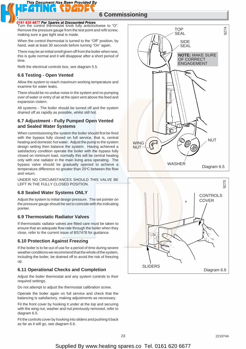
Turn the control thermostat knob fully anticlockwise to “O”.Remove the pressure gauge from the test point and refit screw,making sure a gas tight seal is made.
When the control thermostat is turned to the “Off” position, byhand, wait at least 30 seconds before turning “On” again.
There may be an initial smell given off from the boiler when new,this is quite normal and it will disappear after a short period oftime.
Refit the electrical controls box, see diagram 5.5.
6.6 Testing - Open VentedAllow the system to reach maximum working temperature andexamine for water leaks.
There should be no undue noise in the system and no pumpingover of water or entry of air at the open vent above the feed andexpansion cistern.
All systems - The boiler should be turned off and the systemdrained off as rapidly as possible, whilst still hot.
6.7 Adjustment - Fully Pumped Open Ventedand Sealed Water SystemsWhen commissioning the system the boiler should first be firedwith the bypass fully closed on full service, that is, centralheating and domestic hot water. Adjust the pump to the systemdesign setting then balance the system. Having achieved asatisfactory condition operate the boiler with the bypass fullyclosed on minimum load, normally this will be central heatingonly with one radiator in the main living area operating. Thebypass valve should be gradually opened to achieve atemperature difference no greater than 20oC between the flowand return.
UNDER NO CIRCUMSTANCES SHOULD THIS VALVE BELEFT IN THE FULLY CLOSED POSITION.
6.8 Sealed Water Systems ONLYAdjust the system to initial design pressure. The set pointer onthe pressure gauge should be set to coincide with the indicatingpointer.
6.9 Thermostatic Radiator ValvesIf thermostatic radiator valves are fitted care must be taken toensure that an adequate flow rate through the boiler when theyclose, refer to the current issue of BS7478 for guidance.
6.10 Protection Against FreezingIf the boiler is to be out of use for a period of time during severeweather conditions we recommend that the whole of the system,including the boiler, be drained off to avoid the risk of freezingup.
6.11 Operational Checks and CompletionAdjust the boiler thermostat and any system controls to theirrequired settings.
Do not attempt to adjust the thermostat calibration screw.
Operate the boiler again on full service and check that thebalancing is satisfactory, making adjustments as necessary.
Fit the front cover by hooking it under at the top and securingwith the wing nut, washer and nut previously removed, refer todiagram 6.5.
Fit the controls cover by hooking into sliders and pushing it backas far as it will go, see diagram 6.6.
SLIDERS

Supplied By www.heating spares.co Tel. 0161 620 6677
24221974A
7 Instructions to the User
Diagram 8.1
Diagram 8.2
BAFFLE (8 off)
FLUECONNECTINGELBOW
FLUE DUCTEXTENSION
TOP TURRETFLUE DUCTING 91
3998
03
8 Servicing
Instruct and demonstrate the safe and efficient operation of theboiler, heating system and domestic hot water system.
Advise the user, that to ensure the continued efficient and safeoperation of the boiler it is recommended that it is checked andserviced at regular intervals. The frequency of servicing willdepend upon the particular installation and usage, but in generalonce a year should be enough.
Draw attention, if applicable, to the current issue of the GasSafety (Installation and Use) Regulations, Section 35, which
imposes a duty of care on all persons who let out any propertycontaining a gas appliance.
It is the Law that servicing is carried out by a competent person.
Advise the user of the precautions necessary to prevent damageto the system and building in the event of the heating systembeing out of use during frost and freezing conditions.
Reminder - Leave these instructions and the “Benchmark”logbook with the user.
REMEMBER, When replacing a part on this appliance, use onlyspare parts that you can be assured conform to the safety andperformance specification that we require. Do not usereconditioned or copy parts that have not been clearly authorisedby Hepworth Heating Ltd.
Notes. To ensure the continued efficient and safe operation ofthe boiler it is recommended that it is checked and serviced asnecessary at regular intervals. The frequency of servicing willdepend upon the particular installation conditions and usage,but in general once a year should be enough.
It is the Law that any servicing is carried out by a competentperson.
Before servicing turn off the gas and isolate the electrical supplyto the boiler.
After completing a service always test for gas soundness andcarryout functional check on controls.
Unless stated otherwise all parts are replaced in the reverseorder to removal.
8.1 AccessRemove the controls cover by pulling forward, see diagram 6.6.
Remove the front cover by undoing the wing nut, nut andwasher, lift the front cover off, see diagram 6.6.
Note. As an aid to Servicing the air pressure switch tubeconnection can be used to obtain a products of combustionreading.
Remove the RED tube from the connection on the air pressureswitch and insert the analyser probe into the tube.
Switch on the electrical supply to operate the fan and turn on thegas supply.
On completion of the test switch off the electrical supply and thegas supply and reconnect the red tube to the air pressureswitch.
8.2 Cleaning Heat Exchanger FluewaysDisconnect the air pressure tubes, see diagram 8.1
Remove the blue and red electrical connections from the fan,then loosen jubilee clip to release flue duct extension assembly,see diagram 8.1.
Remove the front right hand flue hood securing screw andslacken off the front left hand one, see diagram 8.3.
Holding the flue duct extension with the right hand and the fanwith the left, draw the fan and flue hood assembly forwardallowing the flue duct extension to rotate slightly in the top turretflue ducting to allow the fan to be withdrawn from the flue ductextension, see diagram 8.1.
Remove the combustion chamber front.
Remove the burner as Section 8.3.
Place a sheet of paper in the base of the combustion chamber.
Remove the baffles, see diagram 8.2.
Clean the heat exchanger flueways with a suitable stiff brush.
Remove the paper together with any debris.
FAN
AIR PRESSURETUBES
ELECTRICALCONNECTIONS
RED
JUBILEECLIP
Diagram 8.3
FLUE HOODRETAININGCLAMP
SECURING SCREWS (4)
JUBILEECLIP
FLUE HOODRETAININGCLAMP
9367

Supplied By www.heating spares.co Tel. 0161 620 6677
25 221974A
8 Servicing
Diagram 8.5
Diagram 8.6
Diagram 8.7
SECURINGSCREW
MAINBURNERINJECTOR
PILOTBURNER
SPRINGCLIP
ELECTRODE
PILOTINJECTOR
4112
4111
4143
8.3 Main BurnerDisconnect the pilot pipe union connector and pilot burner,securing nut and shakeproof washer together with the pilotshield. Remove the pilot burner assembly taking care not todamage the electrode and lead assembly, see diagram 8.4.
Remove the securing screw from the burner support bracket,see diagram 8.5.
Remove the main burner from the main injector at the rear.Raise the burner up and forwards, easing the pilot pipe down,to clear, take care not to damage the combustion chamberinsulation or the pilot p[pipe.
Use a vacuum cleaner or suitable stiff brush to clean the burnerthoroughly, making sure that all the burner ports are clear andunobstructed.
Continue cleaning heat exchanger as Section 8.2.
Note. On refitting and after cleaning the heat exchanger makesure the burner is fitted correctly, that is, located on the maininjector and horizontal.
8.4 Main InjectorWith the main burner removed the main injector can be inspectedand cleaned as necessary, see diagram 8.6.
If removing for cleaning do not use a wire or sharp instrumenton the hole.
Use a little suitable sealant on the external thread when refittingmaking sure a gas tight seal is made.
8.5 Pilot Burner/Electrode and Pilot InjectorClean the pilot burner and electrode.
To remove the electrode release the spring clip, see diagram8.7.
When removing and replacing the pilot injector from the pilotburner take care not to damage the electrode, see diagram 8.7,clean the injector by blowing through it.
Check that the spark gap is as shown in diagram 6.4.
Diagram 8.4
BURNER SUPPORTSCREW
SECURING NUT ANDSHAKEPROOFWASHER
PILOT PIPE
ELECTRODE ANDLEAD ASSEMBLY
UNIONCONNECTOR
4109
8.6 Operational ChecksAfter completing a service and before fitting the case, checkcondition of the case seal and renew if necessary.
Examine flue hood and terminal to make sure they are cleanand clear of obstructions.
Light the boiler and carryout the functional checks as describedin Section 6.
Supplied By www.heating spares.co Tel. 0161 620 6677
26221974A
Diagram 9.1
9 Fault Finding
NEONINDICATORS
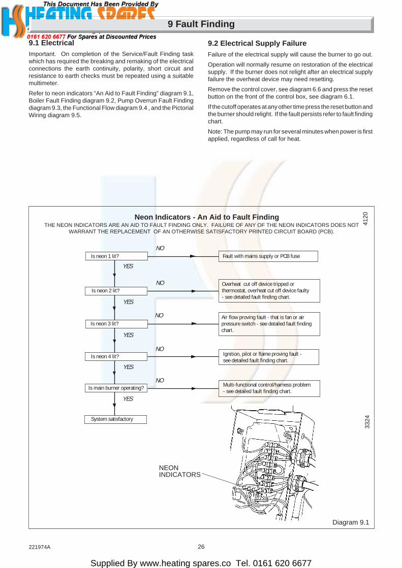
Neon Indicators - An Aid to Fault FindingTHE NEON INDICATORS ARE AN AID TO FAULT FINDING ONLY. FAILURE OF ANY OF THE NEON INDICATORS DOES NOT
WARRANT THE REPLACEMENT OF AN OTHERWISE SATISFACTORY PRINTED CIRCUIT BOARD (PCB).
Fault with mains supply or PCB fuse
Ignition, pilot or flame proving fault -see detailed fault finding chart.
Air flow proving fault - that is fan or airpressure switch - see detailed fault findingchart.
NO
NO
NO
Overheat cut off device tripped orthermostat, overheat cut off device faulty- see detailed fault finding chart.
Is neon 2 lit?
Is neon 4 lit?
System satisfactory
Is neon 3 lit?
Is main burner operating?
Is neon 1 lit?NO
NO
YES
YES
YES
YES
YES
Multi-functional control/harness problem- see detailed fault finding chart.
4120
9.1 ElectricalImportant. On completion of the Service/Fault Finding taskwhich has required the breaking and remaking of the electricalconnections the earth continuity, polarity, short circuit andresistance to earth checks must be repeated using a suitablemultimeter.
Refer to neon indicators “An Aid to Fault Finding” diagram 9.1,Boiler Fault Finding diagram 9.2, Pump Overrun Fault Findingdiagram 9.3, the Functional Flow diagram 9.4 , and the PictorialWiring diagram 9.5.
9.2 Electrical Supply FailureFailure of the electrical supply will cause the burner to go out.
Operation will normally resume on restoration of the electricalsupply. If the burner does not relight after an electrical supplyfailure the overheat device may need resetting.
Remove the control cover, see diagram 6.6 and press the resetbutton on the front of the control box, see diagram 6.1.
If the cutoff operates at any other time press the reset button andthe burner should relight. If the fault persists refer to fault findingchart.
Note: The pump may run for several minutes when power is firstapplied, regardless of call for heat.
3324
Supplied By www.heating spares.co Tel. 0161 620 6677
27 221974A
Diagram 9.2
9 Fault Finding
Is neon 1 lit?
YES YES
Is neon 2 lit?
YES
NO
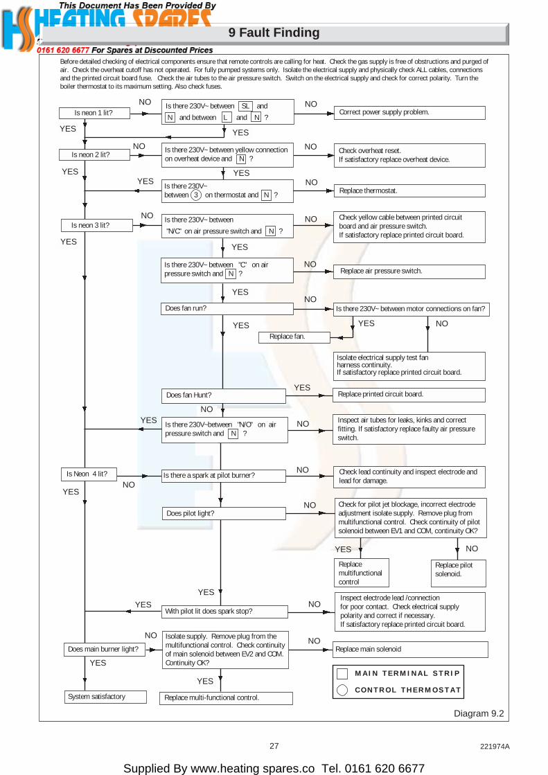
Correct power supply problem.
NOYES Is there 230V~between 3 on thermostat and N ? Replace thermostat.
NO
YES
NOIs neon 3 lit?
Is there 230V~ between
"N/C" on air pressure switch and N ?
YES
Check yellow cable between printed circuitboard and air pressure switch.If satisfactory replace printed circuit board.
YES
NOIs there 230V~ between "C" on airpressure switch and N ? Replace air pressure switch.
Does fan run?
YES
NO
NOYES
Replace fan.
YESReplace printed circuit board.Does fan Hunt?
NO Inspect air tubes for leaks, kinks and correctfitting. If satisfactory replace faulty air pressureswitch.
NO
Is there 230V~between "N/O" on airpressure switch and N ?
NO
NOInspect electrode lead /connectionfor poor contact. Check electrical supplypolarity and correct if necessary.If satisfactory replace printed circuit board.
YES
With pilot lit does spark stop?
NOReplace main solenoid
YES
Replace multi-functional control.
YES
Is Neon 4 lit?NO
Does main burner light?
System satisfactory
NO
YES
NO
YES
YES
NO NOIs there 230V~ between SL and
N and between L and N ?
Is there 230V~ between yellow connectionon overheat device and N ?
YES
Is there 230V~ between motor connections on fan?
YES
Isolate electrical supply test fanharness continuity.If satisfactory replace printed circuit board.
Before detailed checking of electrical components ensure that remote controls are calling for heat. Check the gas supply is free of obstructions and purged ofair. Check the overheat cutoff has not operated. For fully pumped systems only. Isolate the electrical supply and physically check ALL cables, connectionsand the printed circuit board fuse. Check the air tubes to the air pressure switch. Switch on the electrical supply and check for correct polarity. Turn theboiler thermostat to its maximum setting. Also check fuses.
Check overheat reset.If satisfactory replace overheat device.
Is there a spark at pilot burner? Check lead continuity and inspect electrode andlead for damage.
Check for pilot jet blockage, incorrect electrodeadjustment isolate supply. Remove plug frommultifunctional control. Check continuity of pilotsolenoid between EV1 and COM, continuity OK?
Does pilot light?NO
Replacemultifunctionalcontrol
Replace pilotsolenoid.
NOYES
Isolate supply. Remove plug from themultifunctional control. Check continuityof main solenoid between EV2 and COM.Continuity OK?
M A I N T E R M I N A L S T R I P
C O N T R O L T H E R M O S T A T
Supplied By www.heating spares.co Tel. 0161 620 6677
28221974A
9 Fault Finding
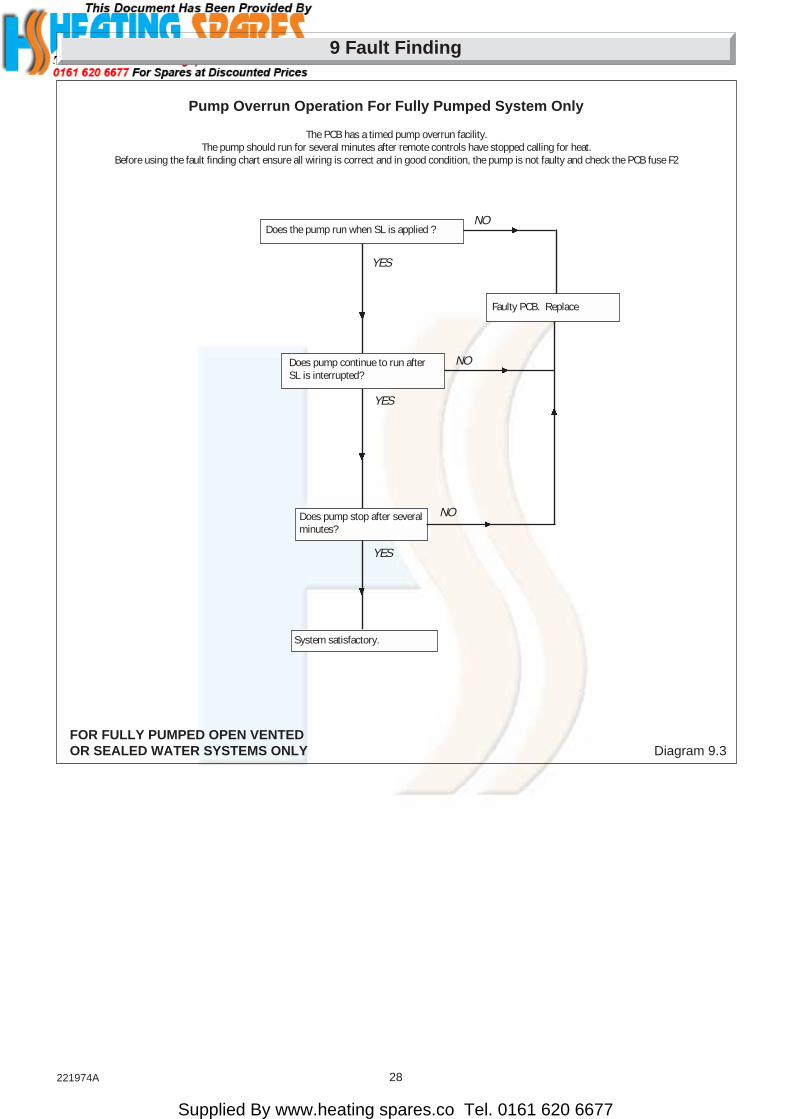
Does pump continue to run afterSL is interrupted?
YES
Does pump stop after severalminutes?
System satisfactory.
Faulty PCB. Replace
NO
YES
YES
NO
NO
Does the pump run when SL is applied ?
Pump Overrun Operation For Fully Pumped System Only
The PCB has a timed pump overrun facility.The pump should run for several minutes after remote controls have stopped calling for heat.
Before using the fault finding chart ensure all wiring is correct and in good condition, the pump is not faulty and check the PCB fuse F2
FOR FULLY PUMPED OPEN VENTEDOR SEALED WATER SYSTEMS ONLY Diagram 9.3

Supplied By www.heating spares.co Tel. 0161 620 6677
29 221974A
9 Fault Finding
FUSEF1 & F2(F1A)
AIR PRESSURE SWITCH CONNECTIONS
SPARKELECTRODE
O/H CUTOFF
CONTROL STAT
FAN
AIRPRESSURESWITCH
PILOTSOLENOID
MAINSOLENOID
N
N
N
N
N
N
N
(N/O) (C)
(N/C)
L
2 3
N
Nb
w
br
yy
y
r b
r
bk b
y
br b
bbkb
KEYbk BLACKbr BROWNb BLUEp PURLPLE
or ORANGEw WHITEr REDy YELLOW
SL
MAIN TERMINAL STRIP CONNECTIONS
CONTROL THERMOSTAT CONNECTIONS
PRINTED CIRCUIT BOARD CONNECTIONS
FULLY PUMPED OPEN VENTEDOR SEALED WATER SYSTEM
PN
9
7
L
PUMPb
brbr
b
b
*RED LINK
*Remove red link between 9 and SL whenfitting a time control etc (if no switch is fitted,link will make the circulation pump run constantly)
F1 F2
or
or
or
p
br
Diagram 9.4
5750

Supplied By www.heating spares.co Tel. 0161 620 6677
30221974A
9 Fault Finding
Diagram 9.5
r
FULLY PUMPED OPENVENTED OR SEALEDWATER SYSTEM
KEY:b - BLUEbk - BLACKbr - BROWNg/y - GREEN/YELLOWor - ORANGEr - REDy - YELLOWw - WHITEp - PURPLE
FAN
MULTI-FUNCTIONALCONTROL
ELECTRODE
PLUG
AIRPRESSURESWITCH
CNO
NC
y
r bbk
g/y CHASSISEARTH
✽ Remove red link between 9 and SL when fitting a time control etc (If no switch is fitted, link will make the circulation pump run constantly)
CHASSIS EARTH
LN
CIRCULATIONPUMP
E
E
N
L 230~50HzPERMANENTMAINSSUPPLYFUSEDAT 3-AMP
N
L
9
8
7
SL
g/y
p
bbr
3-PLUGS
w
y
OVERHEATCUTOFF
SWITCH CONTROL,TIME SWITCH,PROGRAMMER ETC.(if fitted)
✽ SEE NOTE57
51
FUSESF1 & F2(F1A)
g/y
SEQUENCEBOARD g/y
br
b
br
b
g/yy
br
b
or
CONTROLTHERMOSTAT
p
32

Supplied By www.heating spares.co Tel. 0161 620 6677
31 221974A
10 Replacement of Parts
CONTROLTHERMOSTAT
CONTROLKNOB
ELECTRICALCONNECTIONSYELLOW 2 & 3
SPLITGROMMET
RETAININGCLIP
LOCKNUT
ELECTRICALCONNECTIONS
SHAKEPROOFWASHERS ANDSCREWS
5755
Diagram 10.1
10 Replacement of PartsNote. Replacement of parts must only be carried out by acompetent person.
Before replacing any parts isolate the boiler from the electricalsupply and turn the gas supply off at the gas service cock,indicator slot should be vertical.
Unless state otherwise, all parts are replaced in the reverseorder to removal.
After replacing any parts always test for gas soundness and ifnecessary carryout functional check of controls.
10.1 AccessGain access as Section 8.1.
10.2 Control Thermostat diagram 10.1and 10.2Remove and support the electrical control box, refer to Section5.6.
Remove the control knob. Remove the electrical connectionsfrom the thermostat body.
Release the thermostat body by unscrewing the two screws andshakeproof washers in the front of the control box.
Remove the split pin and withdraw the thermostat phial from itspocket. Release the capillary from the base and plastic retainingclip then remove it from the split grommet. Release the capillaryfrom its clips. Remove the thermostat complete from the boiler.
Reassembly note. When fitting the thermostat, make sure thatthe thermostat phial is covered with heat sink compound thenfully inserted into the phial pocket and that the capillary is withinthe gland seal, see diagram 10.2. Remake the electricalconnections. There must be no kinks or sharp bends in thecapillary.
10.3 Over Heat Cutoff Device - diagram 10.1,10.2 and 10.2ARemove and support the electrical control box, refer to Section5.6.
Remove the overheat cutoff electrical connections.
Disconnect the air pressure switch plug from the PCB.
Remove the locking nut from the overheat cutoff.
Release the capillary from the retaining clips then remove itfrom the split grommet.
Loosen the retaining bracket and remove the phial.
When refitting use the heat sink compound supplied.

Supplied By www.heating spares.co Tel. 0161 620 6677
32221974A
10 Replacement of Parts
10.4 Control Board (PCB) - diagram 102ARelease the control box, refer to Section 5.6.
Disconnect the three electrical plugs and ignition lead.
Release the cables from the plastic retaining clip, then disconnectthe cables from the PCB to the main terminal strip, controlthermostat and earth connection.
Release the main terminal strip and plastic label.
Carefully pull the board away from its supports.
When refitting refer to wiring diagram 9.5.
10.5 Pilot Burner and Pilot InjectorProceed as Section 8.3 and 8.5.
10.6 ElectrodeProceed as Section 8.3 and 8.5.
Gain access as Section 5.6 to remove lead from control box.
Diagram 10.2A
ELECTRICAL PLUGS
CHASSISEARTHCONNECTION
MAINTERMINALSTRIPSECURINGSCREW (2)
ELECTRICALCONNECTIONSL BROWN CABLE
PLASTICRETAININGCLIP
ELECTRICALCONNECTIONN BLUE CABLE
SUPPORTPOST (4)
IGNITIONLEAD
BOILERTHERMOSTATELECTRICALCONNECTIONNO.3"YELLOW"CABLE
3328
5756
OVERHEATCUTOFFELECTRICALCONNECTION"WHITE"CABLE
Diagram 10.2
OVERHEATCUTOFF DEVICEPHIAL
9369
PHIAL RETAININGBRACKET SECURINGSCREW
SPLITPIN
CONTROLTHERMOSTATPHIAL POCKETJUBILEE
CLIP SECURINGSCREW (4)
FLUE HOODRETAININGCLAMP (2)

Supplied By www.heating spares.co Tel. 0161 620 6677
33 221974A
10 Replacement of Parts
10.7 Multifunctional Control - diagram 10.3Disconnect the pilot supply by unscrewing the tubing nut at themultifunctional control, take care as there is a restrictor on thepilot pipe.
Disconnect the electrical plug.
Support the multifunctional control, remove the four extendedscrews from the flanged connections at the left and right handside.
Remove and discard the original “O” rings from the flangedconnections and fit the new “O” ring supplied, into recess,before fitting the replacement multifunctional control.
After assembly test for gas soundness and purge in accordancewith the current issue of BS6891.
10.8 Solenoid - diagram 10.3Remove the electrical plug from the multifunctional control.Remove the securing screw and then the solenoid Assembly.
10.9 Main BurnerRemove the main burner as Section 8.3.
10.10 Main InjectorRemove the main burner as Section 8.3.
Remove the main injector as Section 8.4.
10.11 Insulation - 10.4
Combustion Chamber FrontRemove the retaining screw then the insulation.
SidesSlide the insulation out.
RearWith the side insulation removed the rear insulation can beremoved and replaced.
10.12 Viewing Window - diagram 10.5Remove the old self adhesive aluminium foil gasket and the oldmica window. Replace with a new mica window. Peel off thebacking paper and secure with new self adhesive aluminium foilgasket, see diagram 10.5. Ensure no air bubbles are trappedunderneath the foil.
ImportantMake sure that the mica window fully covers the opening andthat the hole in the aluminium foil gasket is centred overopening.
10.13 Air Pressure Switch - diagram 10.6Release the control box as Section 5.6.
Remove the air pressure tubes and electrical connections fromthe PCB, release the screws and remove the switch.
When fitting the replacement make sure that the plastic tubesand electrical connections are made as shown in diagram 9.5and 10.6.
Diagram 10.3
SOLENOIDS
SECURINGSCREW
PILOT PIPETUBING NUT
RESTRICTOR
ELECTRICALPLUG
EXTENDEDSCREW (8)
4123
10.14 Fan - diagram 8.1Remove the electrical connections and disconnect the airDisconnect the air pressure tubes, see diagram 8.1
Remove the blue and red electrical connections from the fan,then loosen jubilee clip to release flue duct extension assembly,see diagram 8.1.
Remove the front right hand flue hood securing screw andslacken off the front left hand one, see diagram 8.3.
Holding the flue duct extension with the right hand and the fanwith the left, draw the fan and flue hood assembly forwardallowing the flue duct extension to rotate slightly in the top turretflue ducting to allow the fan to be withdrawn from the flue ductextension, see diagram 8.1.
Remove the fan from the flue hood by unscrewing the threeretaining screws.
Make sure that the earth connection is remade on to the new fanassembly.
The polarity of the other connections is not important.

Supplied By www.heating spares.co Tel. 0161 620 6677
34221974A
Diagram 10.4 Diagram 10.6
RED
CLEARAIR PRESSURESWITCH TUBES
SECURINGSCREWS
AIRPRESSURE
SWITCHELECTRICALCONNECTIONS CONTROL
BOX
FRONT INSULATION
RETAININGSCREW
SIDE INSULATION
REAR INSULATION
4118
4122
10 Replacement of Parts
Diagram 10.5
SELF ADHESIVEALUMINIUM FOILGASKET
MICA WINDOW
PEEL OFFBACKINGPAPER
OPENING(INSIDE FACEOF THE BOILERFRONT COVER)
7907
9135

Supplied By www.heating spares.co Tel. 0161 620 6677
35 221974A
11 Spare Parts
Key No. Part No. Description GC Part No.
1 800442 Multifunctional control 278 021
2 208040 “O” ring 334 592
3 205710 Injector 278 024
4 203432 Pilot burner 278 023
5 801236 Mica window and gasket
6 800421 Fan assembly 278 008
7 202626 Spark electrode and lead 313 998
8 K3580 Clip 390 983
9 800850 Thermostat
10 202201 Air pressure switch 313 992
11 800400 Control knob 313 609
13 202015 Fuse 334 750
14 900847 Control board PCB
15 800479 Overheat cutoff device 278 188
11.1 Part IdentificationThe key number on the diagram and the list will help to identifythe part.
11.2 OrderingWhen ordering any spare parts please quote the number anddescription from the list together with the model name and serialnumber.
If ordering from Britsh Gas also quote the GC number of theappliance and part.

Supplied By www.heating spares.co Tel. 0161 620 6677
36221974A
Because of our constant endeavour for improvement, details may vary slightly from those shown in these instructions.
11 Spare Parts
Diagram 11.1
4
62
1
10
5
7
8
11
3
13
15
9216
14
9


