Proteon II Management Module Guide
73
Proteon II Management Module Guide ®
Transcript of Proteon II Management Module Guide

Proteon II
Management Module Guide
®

9030915E5i
Notice
Cabletron Systems reserves the right to make changes in speciÞcations and other information contained in this document without prior notice. The reader should in all cases consult Cabletron Systems to determine whether any such changes have been made.
The hardware, Þrmware, or software described in this manual is subject to change without notice.
IN NO EVENT SHALL CABLETRON SYSTEMS BE LIABLE FOR ANY INCIDENTAL, INDIRECT, SPECIAL, OR CONSEQUENTIAL DAMAGES WHATSOEVER (INCLUDING BUT NOT LIMITED TO LOST PROFITS) ARISING OUT OF OR RELATED TO THIS MANUAL OR THE INFORMATION CONTAINED IN IT, EVEN IF CABLETRON SYSTEMS HAS BEEN ADVISED OF, KNOWN, OR SHOULD HAVE KNOWN, THE POSSIBILITY OF SUCH DAMAGES.
Virus Disclaimer
Cabletron has tested its software with current virus checking technologies. However, because no anti-virus system is 100% reliable, we strongly caution you to write protect and then verify that the Licensed Software, prior to installing it, is virus-free with an anti-virus system in which you have conÞdence.
Cabletron Systems makes no representations or warranties to the effect that the Licensed Software is virus-free.
Copyright © April 1998, by Cabletron Systems, Inc. All rights reserved.
Printed in the United States of America.
Order Number: 9030915E5
Cabletron Systems, Inc.P.O. Box 5005Rochester, NH 03866-5005
SPECTRUM
, the
SPECTRUM
IMT/VNM
logo,
DCM
,
IMT
, and
VNM
are registered trademarks, and
SpectroGRAPH
,
SpectroSERVER
,
Inductive Modeling Technology
,
Device Communications Manager
, and
Virtual Network Machine
are trademarks of Cabletron Systems, Inc.
C++
is a trademark of American Telephone and Telegraph, Inc.
UNIX
is a trademark of UNIX System Laboratories, Inc.
OSF/Motif
and
Motif
are trademarks of the Open Software Foundation, Inc.
X Window System
is a trademark of X Consortium, Inc.
Ethernet
is a trademark of Xerox Corporation.

iiProteon II
Management Module Guide
Restricted Rights Notice
(Applicable to licenses to the United States Government only.)
1. Use, duplication, or disclosure by the Government is subject to restrictions as set forth in subparagraph (c) (1) (ii) of the Rights in Technical Data and Computer Software clause at DFARS 252.227-7013.
Cabletron Systems, Inc., 35 Industrial Way, Rochester, New Hampshire 03866-5005.
2. (a) This computer software is submitted with restricted rights. It may not be used, reproduced, or disclosed by the Government except as provided in paragraph (b) of this Notice or as otherwise expressly stated in the contract.
(b) This computer software may be:
(1) Used or copied for use in or with the computer or computers for which it was acquired, including use at any Government installation to which such computer or computers may be transferred;
(2) Used or copied for use in a backup computer if any computer for which it was acquired is inoperative;
(3) Reproduced for safekeeping (archives) or backup purposes;
(4) Modified, adapted, or combined with other computer software, provided that the modified, combined, or adapted portions of the derivative software incorporating restricted computer software are made subject to the same restricted rights;
(5) Disclosed to and reproduced for use by support service contractors in accordance with subparagraphs (b) (1) through (4) of this clause, provided the Government makes such disclosure or reproduction subject to these restricted rights; and
(6) Used or copied for use in or transferred to a replacement computer.
(c) Notwithstanding the foregoing, if this computer software is published copyrighted computer software, it is licensed to the Government, without disclosure prohibitions, with the minimum rights set forth in paragraph (b) of this clause.
(d) Any other rights or limitations regarding the use, duplication, or disclosure of this computer software are to be expressly stated in, or incorporated in, the contract.
(e) This Notice shall be marked on any reproduction of this computer software, in whole or in part.

9030915E5iii
Contents
Preface
What Is in This Guide .......................................................................................................... xiConventions ......................................................................................................................... xiiRelated SPECTRUM Documentation................................................................................. xiiOther Related Documentation ........................................................................................... xiii
Related Hardware Documentation.............................................................................. xiiiGetting Help ....................................................................................................................... xiv
Chapter 1 Introduction
What Is in This Chapter..................................................................................................... 1-1Proteon Router Management Module ............................................................................... 1-1Proteon Router Model Types.............................................................................................. 1-2Proteon Router Applications .............................................................................................. 1-3
Chapter 2 Device View
What Is in This Chapter..................................................................................................... 2-1Accessing the Device View ................................................................................................. 2-1Logical Interface Icons ....................................................................................................... 2-4
Device Topology View Label......................................................................................... 2-5IF Status View Label ................................................................................................... 2-5IF ConÞguration View Label ....................................................................................... 2-5IF Address Translation Table Label............................................................................ 2-7Network Information Panel Label .............................................................................. 2-7Performance View Label .............................................................................................. 2-7Detail View ................................................................................................................... 2-8Interface Threshold View............................................................................................. 2-9
Interface Options Panel...................................................................................................... 2-9Find............................................................................................................................... 2-9Network Information ................................................................................................. 2-10Interface Description ................................................................................................. 2-10
Gauge Control Panel ........................................................................................................ 2-10Selected Attribute ...................................................................................................... 2-10Gauge Mode................................................................................................................ 2-10Gauge Type................................................................................................................. 2-12

iv
Proteon IIManagement Module Guide
Chapter 3 ConÞguration Views
What Is in This Chapter .....................................................................................................3-1Accessing the Device ConÞguration View..........................................................................3-1Device ConÞguration View .................................................................................................3-2
Interface ConÞguration Table ......................................................................................3-2Diagnostic View...................................................................................................................3-6
Chapter 4 Event and Alarm Messages
What Is in This Chapter .....................................................................................................4-1Proteon Router Events and Alarms ...................................................................................4-1
Chapter 5 Application View
What Is in This Chapter .....................................................................................................5-1Accessing the Application Views ........................................................................................5-2
Proteon Ether Application Performance View ............................................................5-4Proteon Token Ring Application Views .......................................................................5-6
Proteon Token Ring Performance View.................................................................5-6Isolated Errors .................................................................................................5-6Non-Isolated Errors.........................................................................................5-7
Proteon Token Ring Information View..................................................................5-8Proteon Serial Application Views ..............................................................................5-11
Proteon Serial Performance View........................................................................5-11Proteon Serial Port Status View..........................................................................5-12
FDDI Application Views.............................................................................................5-13FDDI Performance View ......................................................................................5-13MAC Table ............................................................................................................5-13SMT Table.............................................................................................................5-14

9030915E5v
Chapter 5 Application View (continued)
Routing Application Views ............................................................................................... 5-15Generic Routing ......................................................................................................... 5-15
Generic Routing Performance View.................................................................... 5-15Generic Routing Detail View............................................................................... 5-15
Proteon IP Routing Application Views...................................................................... 5-16Proteon IP ConÞguration View ........................................................................... 5-16Proteon IP Routing Table .................................................................................... 5-17Proteon IP Address Table .................................................................................... 5-17Proteon IP Fragmentation View ......................................................................... 5-18Proteon IP Reassembly View .............................................................................. 5-18Proteon IP Detail View........................................................................................ 5-19
OSPF Application Views ............................................................................................ 5-20OSPF ConÞguration View ................................................................................... 5-20Area Table ............................................................................................................ 5-21Area Metric Table ................................................................................................ 5-22LS Database......................................................................................................... 5-22Address Range Table ........................................................................................... 5-23Host Table ............................................................................................................ 5-24Interface Table ..................................................................................................... 5-24Interface Metric Table ......................................................................................... 5-26Virtual Interface Table ........................................................................................ 5-26Neighbor Table..................................................................................................... 5-27Virtual Neighbor Table........................................................................................ 5-28
Index

vi
Proteon IIManagement Module Guide

9030915E5vii
Figures
Chapter 2 Device View
Figure 2-1. Proteon Router Device View ................................................................................. 2-3Figure 2-2. Logical Interface Icon ........................................................................................... 2-4
Chapter 5 Application View
Figure 5-1. Application View (Icon Mode) .............................................................................. 5-3Figure 5-2. Application View (List Mode) ............................................................................... 5-4

viiiProteon II
Management Module Guide

9030915E5ix
Tables
Chapter 1 Introduction
Table 1-1. Model Type Descriptions ....................................................................................... 1-2
Chapter 2 Device View
Table 2-1. Interface Status Label Definitions ....................................................................... 2-5Table 2-2. Packet Breakdown Pie Chart................................................................................ 2-8Table 2-3. Error Breakdown Pie Chart.................................................................................. 2-8Table 2-4. Discard Breakdown Pie Chart .............................................................................. 2-9Table 2-5. Gauge Totals and Percentages Mode Attributes and Color Definitions........... 2-11Table 2-6. Gauge Rates Mode Attributes and Color Definitions ........................................ 2-11
Chapter 3 ConÞguration Views
Table 3-1. General Proteon Router Interface Types.............................................................. 3-3Table 3-2. Proteon Specific Router Interface Types .............................................................. 3-4
Chapter 4 Event and Alarm Messages
Table 4-1. Events and Alarms ................................................................................................ 4-2
Chapter 5 Application View
Table 5-1. Ethernet Connection Interface Types................................................................... 5-4Table 5-2. Ring Error Status Definitions............................................................................... 5-9Table 5-3. Adapter Error Check Descriptions ....................................................................... 5-9Table 5-4. Level Converter Types......................................................................................... 5-12Table 5-5. Modem Signal Acronym Definitions................................................................... 5-12Table 5-6. Modem Signal State Definitions ......................................................................... 5-13Table 5-7. Packet Breakdown Pie Chart.............................................................................. 5-19Table 5-8. Error Breakdown Pie Chart................................................................................ 5-19Table 5-9. Discard Breakdown Pie Chart ............................................................................ 5-20Table 5-10. Link State Advertisement Types ........................................................................ 5-23Table 5-11. OSPF Interface States......................................................................................... 5-25Table 5-12. OSPF Neighbor States ........................................................................................ 5-28

xProteon II
Management Module Guide

9030915E5 Prefacexi
Preface
Use this Guide if you are going to manage a Proteon Router module through SPECTRUM. Before reading this manual, you should be familiar with SPECTRUMÕs operation. You should also be familiar with any network management and hardware requirements described in the Proteon Router documentation.
What Is in This Guide
The following chapter descriptions outline the organization of the
Proteon II Management Module Guide
.
Chapter Description
Chapter 1
Introduction
Describes the Proteon Router management module and model types.
Chapter 2
Device View
Describes the Device viewÕs representations of the Proteon Router devices, as well as the views available from the Device menu.
Chapter 3
ConÞguration Views
Describes the ConÞguration views available for the Proteon Router which provide network management information for the devices.
Chapter 4
Event and Alarm Messages
Contains a listing and explanation of the alarm/event messages generated in the Event Log or Alarm Manager for the Proteon Router management module.
Chapter 5
Application Views
Describes the Application views for the Proteon Router management module and the major and minor application information provided by the views.
Conventions
Prefacexii
Proteon IIManagement Module Guide
Conventions
In this manual the following conventions are used.
¥ Command names are printed in
bold
; for example,
Clear
or
Save & Close
.
¥ Menu selections to access a view are printed in
bold
; for example,
ConÞguration
or
Detail
.
¥ Buttons are represented by a shadowed box; for example:
¥ Book or chapter titles are in
italics
; for example,
SPECTRUM Views.
Related SPECTRUM Documentation
When using this guide, you should have a clear understanding of SPECTRUM functionality and navigation techniques as described in the Administration, Operation, and following documentation:
SPECTRUM Report Generator UserÕs Guide
Getting Started with SPECTRUM for Operators
Getting Started with SPECTRUM for Administrators
How to Manage Your Network with SPECTRUM
Help

9030915E5 Prefacexiii
Other Related Documentation
Other Related Documentation
Refer to the following documentation for more information on managing TCP/IP-based networks:
LAN Troubleshooting Handbook
, Mark Miller (1989, M&T Publishing, Inc.)
The Simple Book Ñ An Introduction to Management of TCP/IP-based Internets
, Marshall T. Rose, Performance Systems International, Inc.
Computer Networks
, Andrew S. Tanenbaum, Prentice-Hall, Inc.
Local Area Networks, Architectures and Implementations
, James Martin & Kathleen K. Chapman for the Arben Group, Inc. (1989, Prentice-Hall, Inc.)
Related Hardware Documentation
Refer to the following documentation to learn more about the Proteon Routers:
Proteon Bridging Router Reference Guide
, (Part Number 42-040242-00) Proteon, Inc.
Event Logging System Messages Guide
, (Part Number 42-040209-00)Proteon, Inc.
CNX 500 Installation Guide
, (Part Number 42-040219-00) Proteon, Inc.
CNX 500 Diagnostics Guide
, (Part Number 42-040252-00) Proteon, Inc.
Bridging Routing Command Guide
, (Part Number 42-040241-00)Proteon, Inc.

Getting Help
Prefacexiv
Proteon IIManagement Module Guide
Getting Help
For additional support for SPECTRUM products, or to make comments or suggestions regarding SPECTRUM or this manual, contact Cabletron Systems Technical Support via one of the following means:
Location Mail FAX Telephone
North America
Cabletron Systems, Inc.P. O. Box 5005Rochester, NH 03866-5005
E-mail:
603-337-3075 603-337-3500
Europe
Cabletron Systems, Ltd.Network HouseNewbury Business ParkLondon Road, NewburyBerkshire, England RG13 2PZ
E-mail:
(*)-44-635-552062 (*)-44-635-580000
PaciÞc
Cabletron Systems, Inc.Allambie Grove Estate25 FrenchÕs Forest Road EastFrenchÕs Forest, NSW 2086Sydney, Australia
E-mail:
(*)-61-2-950-5950 (*)-61-2-950-5900
Japan
Cabletron Systems, KKHamamatsucho MK Bldg.4th Floor1-4-12 Kaigan, Minato-KuTokyo 101 Japan
E-mail:
(*)-81-3-3459-1985 (*)-81-3-3459-1981
Singapore
Cabletron Systems, Inc.85 Science Park Drive#03-03/04The CavendishSingapore 051
E-mail:
(*)-65-7763382 (*)-65-7755355
Germany
Cabletron Systems GmbHDreieich ParkIm GeÞerth 13d63303 DreieichFrankfurt, Germany
E-mail: [email protected]
(*)-49-6103/991-229 (*)-49-6103/991-269
*International Operator Code
Questions About SPECTRUM Documentation?Send your questions, comments or suggestions regarding SPECTRUM documentation to the Technical Communications Department directly via the following internet address:
9030915E5 Introduction1-1
Chapter 1
Introduction
What Is in This ChapterThis chapter describes the SPECTRUM Management Module for the Proteon Router (Models DNX300, CNX500, and CNX600). It also provides the model type names assigned to the models in SPECTRUM. The model type name refers to the template used to specify attributes, actions, and associations for device models in SPECTRUM.
Proteon Router Management Module
The Proteon Router Management Module manages Proteon Router devices using the SNMP network management agent and the Management Information Bases (MIBs), included with the management module.
NOTE
If you are running a previous version of SPECTRUM, the following user interface aspects may differ from those in SPECTRUM version 4.0:
¥ Order and names of menu selections
¥ Navigational features (mouse button functionality)
For information about menu selections and navigating within previous versions of SPECTRUM, refer to the SPECTRUM System UserÕs Guide. For information about menu selections and navigating within SPECTRUM version 4.0, refer to the SPECTRUM Views reference.
Proteon Router Management Module

Proteon Router Model Types
Introduction1-2
Proteon IIManagement Module Guide
Proteon Router Model TypesThere are Þve Proteon Router model types supported by SPECTRUM. Four of these model types are described in this manual, the Þfth model type, Rtr_Proteon, is described in the Management Module Guide for the Proteon Router. One generic model type, Router_Proteon, is provided for Proteon Router models without a known corresponding model type designation in SPECTRUM. The Proteon Router model types described in this manual are:
¥ PteonCNX500¥ PteonCNX600¥ PteonDNX300¥ Router_Proteon
Table 1-1 provides the model type names for the Proteon Router model types described in this manual, and a brief description of the physical Proteon Router devices that these models represent.
Table 1-1. Model Type Descriptions
Model Type Name Router Description
PteonCNX500 This model type emulates the Proteon CNX500 Router.
PteonCNX600 This model type emulates the Proteon CNX600 Router.
PteonDNX300 This model type emulates the Proteon DNX300 Router.
Router_Proteon This model type emulates Proteon Router models CNX500, CNX600, and DNX300.
NOTE
The Router_Proteon model type can be used to model the Proteon DNX300, CNX500, and CNX600 Routers; however, if the actual device type is known, use the model type speciÞc to that device. The Rtr_Proteon model type (sold as a separate module) is used to model the Proteon p4100 and p4200 Routers. If the Router_Proteon model type is used to model the p4100 or p4200, the icon will display the correct device type, but all of the data speciÞc to that model will be lost.
9030915E5 Introduction1-3
Proteon Router Applications
Proteon Router ApplicationsThe Proteon Router supports common and Device-speciÞc applications. Common applications are described in the MIB II Applications, Bridging Applications, and Miscellaneous Applications references, and are as follows:
¥ MIB-II (SNMP2_Agent)- ICMP (ICMP_App)- IP (IP2_App)- System (System2_App)- UDP (UDP2_App)
Device-speciÞc applications are described in Chapter 5, Application Views, and are as follows:
¥ Routing (GenRtrApp)- PteonIPRtr (PteonIPApp)- OSPF (OSPF2RtrApp)
¥ Proteon Ethernet (PteonEthApp)¥ Proteon Serial (PteonSerial)¥ Proteon Token Ring (PteonTRApp)

Proteon Router Applications
Introduction1-4
Proteon IIManagement Module Guide

9030915E5 Device View2-1
Chapter 2
Device View
What Is in This ChapterThis chapter describes the Device view for the Proteon II. The Device view for the Proteon Router devices allows you to view the logical representations of the Proteon Router devices and ports. The Device view also provides you with menu bar access to views that monitor and control the Proteon RouterÕs interfaces. The Device view gives an actual representation of the Proteon RouterÕs conÞguration. If the conÞguration changes you see the corresponding change within this view. This change in the view occurs after the modelÕs next polling cycle. Figure 2-1 shows an example of a Proteon Router Device view.
Accessing the Device ViewAccess the Device view using one of the following methods.
¥ Double-click on the Device view button of the Proteon RouterÕs device icon.
¥ Highlight the Proteon RouterÕs device icon and select Device from the Icon Subviews menu.
Device View Button

Accessing the Device View
Device View2-2
Proteon IIManagement Module Guide
Figure 2-1 provides an example of a Proteon Router Device view.
Go BackGo UpIcon SubviewsView PathNew ViewBookmarksView HistoryCurrent View Info...Notes...Jump by name...ZoomMap Hierarchy
CloseNavigateAlarmsPerformanceNotes...UtilitiesZoomDeviceDevTop

9030915E5 Device View2-3
Accessing the Device View
Figure 2-1. Proteon Router Device View
* File View Help?
Primary Landscape 0x00400000 - VNM Host - of type CNX500
Filter
Interface Description
Network Information ADDRESSPhysical
2 ONETHERNET
0
0
Model Name
Contact
Description
Location
Network Address System Up Time
Manufacturer
Device Type
Serial NumberPrimary-Application
Proteon Router
CNX500
Null
1 OFFFDDI
0
0Null
3 OFFETHERNET
0
0Null
4 OFFISO88025
0
0Null
5 OFFISO88025
0
0Null
6 OFFPPTPS
0
0Null
7 OFFPPTPS
0
0Null
Interface Options PanelDevice Icon Panel
Logical Interface Icons

Logical Interface Icons
Device View2-4
Proteon IIManagement Module Guide
Logical Interface IconsA Proteon Router Device View displays a logical representation of each of the routerÕs interfaces. An interface icon represents each port on the Proteon Router. Additional views for the interface can be accessed by single-clicking the interface icon to highlight and selecting Icon Subviews from the File menu, single-clicking on the icon with the middle or right mouse button, or double-clicking on the iconÕs zones. The Port Notes facility is also accessed from the Icon Subviews menu.
The Logical Interface Icon consists of six zones, providing conÞguration and performance information.Figure 2-2 provides a detailed illustration of the Logical Interface Icon and the following sections detail each icon zone.
Figure 2-2. Logical Interface Icon
a. Device Topology View Label
b. IF Status View Label
c. IF ConÞguration View Label
d. IF Address Translation Table Label
e. Network Information Panel Label
f. Performance View Label
CloseNavigateAlarmsPerformanceNotesUtilitiesDevTopDetailIF StatusIF ConÞgurationIF Address Translation TableNetwork Information PanelThresholdsModel Information
(a) (b)
(e)
(d)
(c)
(f)

9030915E5 Device View2-5
Logical Interface Icons
Device Topology View Label
Device Topology View Label
The zone also displays the interface number. Double-clicking on this zone opens the Proteon RouterÕs Device Topology View.
IF Status View Label
The IF Status label displays a text label and an appropriate background color to represent the current status of the interface. Table 2-1 shows the possible interface statuses and their respective colors.
Double-clicking on this IF Status View label accesses the Interface Status View which provides the following information on the status of the interface:
Operational StatusA read-only indicator button displaying the current operational state of the interface (ON, OFF, or Testing).
Administrative StatusThe desired operational state of the interface (ON, OFF, or Testing) selectable through the File/Save All Changes feature.
IF ConÞguration View Label
The IF ConÞguration View label displays the type of Proteon Router interface. Possible interface types are shown in Table 2-1. Double-clicking on the IF ConÞguration View label accesses the Interface ConÞguration View, which provides the following information for the interface:
Operation StatusThe current operational state of the interface (On, Off, or Testing).
Table 2-1. Interface Status Label DeÞnitions
Operational Status Administrative Status Text Display Color
ON ON ON Green
OFF OFF OFF Blue
OFF ON OFF Yellow
Testing Testing Test Red
Logical Interface IconsIF ConÞguration View Label
Device View2-6
Proteon IIManagement Module Guide
Admin. StatusThe desired operational state of the interface (On, Off, or Testing) selectable through the File/Save All Changes feature.
Last ChangeThe System UpTime value when the interface entered its current operational state.
Physical AddressThe Ethernet (MAC) address of the interface.
BandwidthThe estimated bandwidth of the interface measured in bits per second. For interfaces that do not vary in bandwidth, or no accurate estimate can be made, a nominal bandwidth is provided.
Packet SizeThe largest packet that can be transmitted or received by the port measured in octets.
Queue LengthThe length of the outbound packet queue in packets.
Status Register AddressThe Command and Status Register address for the interface.
No. Failed Maintenance ChecksThe number of failed maintenance checks since the last successful maintenance check.
Max Maintenance FailuresThe number of maintenance check failures permitted before a self test is run.
Total Maintenance FailuresThe total number of maintenance failures on this interface.
Next Interface MaintenanceThe number of seconds before the next interface maintenance.
Time Between Maint. ChecksThe number of seconds between maintenance checks.
Self Test SuccessesThe total number of successful self tests on this interface.
Self Test FailuresThe total number of failed self tests on this interface.
Next Self TestThe number of seconds before the next self test.
Multi-Bus Interrupt VectorThe multi-bus interrupt vector for the interface.

9030915E5 Device View2-7
Logical Interface Icons
IF Address Translation Table Label
IF Address Translation Table Label
The IF Address Translation Table label displays the physical address of the Proteon Router interface. Double-clicking on the IF Address Translation Table label opens the Interface Address Translation Table. This table cross-references device IP addresses to device MAC (Ethernet) addresses for selected nodes between networks. Double-clicking on any column entry opens an address-speciÞc Address Translation Table Information View. Clicking on a column title displays the applicable action button(s) described below.
Columns in the table can be sorted incrementally by single-clicking the Sort button.
A particular statistical entry can be located by single-clicking the Find button and entering the statistic.
The table can be updated by single-clicking the Update button.
Network Information Panel Label
Double-clicking on this zone of the Logical Interface Icon accesses the Network Information Panel. This panel provides Name, Network Address, and subnet mask information for the interface. Any of the network information entries from this panel can be displayed on zone (f) of the Logical Interface Icon. Refer to the Interface Options Panel section of this chapter.
Performance View Label
Double-clicking on this zone opens the Performance View for the interface. This area is also a Logical Gauge which is described in the next section. The Performance View provides pie charts displaying error information for each interface.
Sort
Find
Update

Logical Interface IconsDetail View
Device View2-8
Proteon IIManagement Module Guide
Detail View
The Interface Detail View is accessed by selecting Detail View from the Icon Subviews menu. This view provides three color-coded pie charts (refer to Table 2-2, Table 2-3, and Table 2-4) displaying the following packet, error, and discard breakdown information for the interface. Each statistic is presented as a total amount since the interface was initialized and as a percentage of overall network trafÞc.
Table 2-2. Packet Breakdown Pie Chart
Statistic DeÞnition
Delivered Packets delivered to a higher level protocol.
Transmitted Packets transmitted through this interface.
Errors Packets containing errors preventing them from being delivered to a higher level protocol.
Discards Packets discarded even though no errors were detected to make them undeliverable - such packets may have been discarded to increase buffer space.
Table 2-3. Error Breakdown Pie Chart
Statistic DeÞnition
In Errors Packets received containing errors.
Out Errors Packets transmitted containing errors.

9030915E5 Device View2-9
Interface Options Panel
Interface Threshold View
Interface Threshold View
The Interface Threshold View is accessed by selecting Thresholds from the Icon Subviews menu. The Interface Threshold View allows a user to set statistical thresholds on a per interface basis with the File/Save All Changes feature. Thresholds can be set for the following statistics:
¥ Load¥ Packet Rate¥ Error Rate¥ % Discarded
Interface Options PanelThe Interface Option Panel area of the Device View allows you to modify the presentation of the Logical Interface Icon.
Find
The Find area of the Interface Options Panel allows you to Þnd a speciÞc interface by selecting either the interfaceÕs Physical Address, IP Address, Type, or Network Name and entering the appropriate information in the Pop-up dialog box. Once the information is entered, the corresponding area of the speciÞc Logical Interface Icon will appear highlighted. The Find option will also look for and display other addresses in the Network Information Panel.
Table 2-4. Discard Breakdown Pie Chart
Statistic DeÞnition
Unknown Locally addressed packets received successfully but discarded because of an unknown or unsupported protocol.
In Discards Received packets discarded even though no errors were encountered to prevent their continued processing - such packets may have been discarded to increase buffer space.
Out Discards Transmitted packets discarded even though no errors were encountered to prevent their continued processing - such packets may have been discarded to increase buffer space.

Gauge Control PanelNetwork Information
Device View2-10
Proteon IIManagement Module Guide
Network Information
The Network Information area of the Interface Options Panel allows you to select what interface information is displayed in the Network Information Label zone of that interfaceÕs Logical Interface Icon. Possible selections are ADDRESS, NAME, or MASK.
Interface Description
Selecting a Logical Interface Icon displays the type of interface in the Interface Description area of the Interface Options Panel. Double-clicking on the Interface Description Þeld accesses the Interface Description Map View which provides a tableÕs mapping interface numbers to their descriptions. This view can also be accessed by single-clicking on the Interface Options Panel to highlight it and then selecting Inf Description Map from the Icon Subviews menu. Double-clicking on a column entry in the Interface Description Map accesses the Interface ConÞguration View described previously.
Gauge Control PanelThe Gauge Control Panel allows you to change the type of statistical information presented in the Logical Gauge area of the Logical Interface Icon. To access the Gauge Control Panel, either double-click on the Interface Options Panel or single-click on the panel to highlight it and then select Gauge Control Panel from the Icon Subviews menu.
Selected Attribute
This area of the Gauge Control Panel allows you to select the statistical attribute displayed on the Logical Interface IconÕs Gauge. The label changes color to reßect the attribute selected. Table 2-5 and Table 2-6 provide a list of the attributes and their corresponding colors.
Gauge Mode
This area of the Gauge Control Panel allows you to select the mode presented by the Logical Gauge. Possible selections are Totals, Rates, or Percentages. The Percentages selection represents the percentage of the interface compared to the rest of the interfaces. Table 2-5 shows the displayed attributes and their color deÞnitions if the Totals or Percentages modes are selected. Table 2-6,

9030915E5 Device View2-11
Gauge Control Panel
Gauge Mode
shows the displayed attributes and their color deÞnitions if the Rates model is selected.
Table 2-5. Gauge Totals and Percentages Mode Attributes and Color DeÞnitions
Selected Attribute Color
In Errors Orange
Out Errors Orange
In Packets Blue
Out Packets Blue
Unknown Protocols Yellow
In Discards Beige
Out Discards Beige
In Octets Green
Out Octets Green
Table 2-6. Gauge Rates Mode Attributes and Color DeÞnitions
Selected Attribute Color
Packet In Rate Blue
Packet Out Rate Blue
Packet Rate Blue
In Error Rate Orange
Out Error Rate Orange
Error Rate Orange
Discard In Rate Beige
Discard Out Rate Beige
Discard Rate Beige
Load In Green
Load Out Green
Load Green
Gauge Control PanelGauge Type
Device View2-12
Proteon IIManagement Module Guide
Gauge Type
This option allows you to select either a numeric or linear presentation of the Logical Gauge. The following buttons are available in the Gauge Control Panel:
Apply the current selections to the Logical Gauge. The settings will not be saved.
Save the current gauge settings while running SpectroGRAPH.
Reset back to the last Keep Settings selections.
Close the Gauge Control Panel.
Reset back to the default attribute of In Errors.
Apply
Keep Settings
Reset
Close
Default

9030915E5 ConÞguration Views3-1
Chapter 3
ConÞguration Views
What Is in This ChapterThis chapter provides general descriptions of the ConÞguration view and Diagnostic view which are available for the Proteon Router devices. These views allow you to access device-speciÞc conÞguration and diagnostic information.
Accessing the Device ConÞguration ViewAccess the ConÞguration view using one of the following methods:
¥ Double-click on the Device ConÞguration view label of the Proteon Router device icon.
¥ Highlight the Proteon Router device icon and select ConÞguration.
Device ConÞguration View Label

Device ConÞguration View
ConÞguration Views3-2
Proteon IIManagement Module Guide
Device ConÞguration ViewThe Device ConÞguration view for the Proteon Router provides information on the Proteon RouterÕs network, host, port, and model conÞguration.
Interface ConÞguration Table
The Interface ConÞguration table provides the following port conÞguration information for each of the Proteon RouterÕs ports.
IndexThe port number on the Proteon Router.
DescriptionA textual description of the interface including the name of the manufacturer, the product name and version number of the hardware interface.
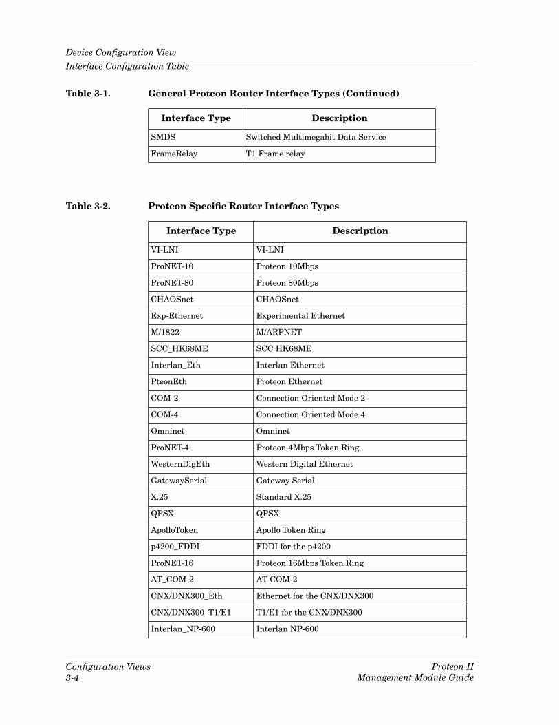
Pteon If TypeThe type of interface for the port. Interface types and descriptions are shown in Table 3-1 and Table 3-2. Table 3-1 lists general interfaces supported by Proteon Routers. Table 3-2 lists interfaces that are speciÞc to Proteon Routers.
Go BackGo UpIcon SubviewsView PathNew ViewBookmarksView HistoryCurrent View Info...Notes...Jump by name...ZoomMap Hierarchy
DeviceDevTopApplicationAcknowledge
ConfigurationModel InformationPrimary Application
Flash Green Enabled
NOTE
This table will fail if Þrmware is not at Rev. 13 or greater. Older devices do not support the new attribute.

9030915E5 ConÞguration Views3-3
Device ConÞguration View
Interface ConÞguration Table
Table 3-1. General Proteon Router Interface Types
Interface Type Description
OTHER None of the following
RR1822 Regular 1822
HDH1822 HDLC Distant Host protocol
DDNX25 Defense Data Network X.25
RFC877X25 RFC877 X.25
ETHERNET Ethernet CSMA/CD
ISO88023 ISO CSMA/CD
ISO88024 ISO token bus
ISO88025 ISO token ring
ISO88026 ISO man
STARLAN StarLAN IEEE 802.3
10MBIT ProNET 10 Mbps
80MBIT ProNET 89 Mbps
HYPCHAN Hyperchannel
FDDI Fiber Distributed Data Interface
LAPB X.25 Line Access Procedure, Balanced
SDLC IBM Synchronous Data Link Control protocol
T1 T1 link (USA and Japan)
CEPT T1 link (Europe)
BISDN Basic Integrated Services Digital Network
PISDN Proprietary Integrated Services Digital Network
PPTPS Proprietary Point to Point Serial
PPP Point to Point protocol
SFTWARLPBK Software Loopback
CLNP-IP Connectionless Network Protocol over IP
Enet3MB Ethernet 3 Mbps
XNS-IP Xerox Network Service Protocol over IP
SLIP Generic Serial Line IP
ULTRA ULTRA Technologies
T-3 T3 link
Device ConÞguration ViewInterface ConÞguration Table
ConÞguration Views3-4
Proteon IIManagement Module Guide
SMDS Switched Multimegabit Data Service
FrameRelay T1 Frame relay
Table 3-1. General Proteon Router Interface Types (Continued)
Interface Type Description
Table 3-2. Proteon SpeciÞc Router Interface Types
Interface Type Description
VI-LNI VI-LNI
ProNET-10 Proteon 10Mbps
ProNET-80 Proteon 80Mbps
CHAOSnet CHAOSnet
Exp-Ethernet Experimental Ethernet
M/1822 M/ARPNET
SCC_HK68ME SCC HK68ME
Interlan_Eth Interlan Ethernet
PteonEth Proteon Ethernet
COM-2 Connection Oriented Mode 2
COM-4 Connection Oriented Mode 4
Omninet Omninet
ProNET-4 Proteon 4Mbps Token Ring
WesternDigEth Western Digital Ethernet
GatewaySerial Gateway Serial
X.25 Standard X.25
QPSX QPSX
ApolloToken Apollo Token Ring
p4200_FDDI FDDI for the p4200
ProNET-16 Proteon 16Mbps Token Ring
AT_COM-2 AT COM-2
CNX/DNX300_Eth Ethernet for the CNX/DNX300
CNX/DNX300_T1/E1 T1/E1 for the CNX/DNX300
Interlan_NP-600 Interlan NP-600

9030915E5 ConÞguration Views3-5
Device ConÞguration View
Interface ConÞguration Table
Module IDThe interface card type for this module. Possible entries are SingleEthernet, SingleToken, DualT1/E1, FDDI, DualEthernet, DualToken, QuadSerial, ISDN, 255-NVRAM0nl (Used when there is no physical interface but a conÞguration exists in NVRAM. Any other value should be construed as an unknown type.)
BandwidthThe estimated bandwidth of the interface measured in bits per second. For interfaces that do not vary in bandwidth or for which no accurate estimate can be made, a nominal bandwidth is provided.
Physical AddressThe Ethernet (MAC) address of the port.
Operation StatusThe current operational state of the port (On, Off, or Testing).
Admin StatusThe desired operational state of the port (On, Off, or Testing) selectable through the File/Save All Changes feature.
Last Change The System UpTime value when the port entered its current operational state.
Queue LengthThe length of the outbound packet queue in packets.
SDLC_Relay_on_Gateway SDLC Relay on Gateway
SDLC_Relay_on_ATComsl SDLC Relay on ATComsl
SDLC_Relay_on_csl SDLC Relay on csl
SRB_Tunnel SRB Tunnel
SDLC_Relay SDLC Relay
NationalEth National Ethernet
X.25_on_atcomsl X.25 on ATComsl
X.25_on_CNX_csl X.25 for CNX, csl
X.25_on_DNX300_csl X.25 for DNX300, csl
CNX_Quad_Serial CNX Quad Serial
Table 3-2. Proteon SpeciÞc Router Interface Types (Continued)
Interface Type Description

Diagnostic ViewInterface ConÞguration Table
ConÞguration Views3-6
Proteon IIManagement Module Guide
Packet SizeThe largest Maximum Transmission Unit (MTU) that can be transmitted or received by the port measured in octets.
The IF Address Translation button accesses the Interface Address Translation Table. This table cross-references device IP addresses to device MAC (Ethernet) addresses for selected nodes between networks. Double-clicking on any column entry opens an address-speciÞc Address Translation Table Information View.
Diagnostic ViewThe Diagnostic view provides information on the Proteon RouterÕs status over time. Buttons are also provided to access the Event Log and Alarm Manager. Access the Diagnostic view by clicking on the Device icon and selecting Diagnostic from the Icon Subviews menu. The Diagnostic view provides the following information:
Status StartsThe number of times that the router has started since the last reload. This value is the number of restarts plus one.
Status CrashesThe number of times the router has crashed since the last reload.
Status Reload TimeThe time, in hundredths of a second, since the router software was reloaded.
Status Crash MsgThe last crash message. If the router has not crashed since the last reload, the message will indicate this.
This button accesses the Event Log, which provides a history of the Proteon RouterÕs status at speciÞc times.
This button accesses the Alarms View which provides information on current alarm conditions (if any) for the Proteon Router.
IF Address Translation
Events
Alarms

9030915E5 Event and Alarm Messages4-1
Chapter 4
Event and Alarm Messages
What Is in This ChapterThis chapter describes the types of events and alarms generated by the Proteon Router and any probable cause messages corresponding to these alarms.
Proteon Router Events and AlarmsThis table describes the event messages appearing in the Event Log, and any corresponding probable cause messages that may displayed in the Enterprise Alarm Manager for the Proteon Router.

Proteon Router Events and Alarms
Event and Alarm Messages4-2
Proteon IIManagement Module Guide
Table 4-1. Events and Alarms
Message in the Event Log Alarm View Probable Cause Message
CsEvFormat/Event00010002
{d "%w- %d %m-, %y - %T"} - A Proteon Router, {t} (name - {m}) has been reloaded. SystemUpTime = {I 1}. (Trap type : 0x10002) - (event [{e}])
No Probable Cause Message
CsEvFormat/Event00010003
{d "%w- %d %m-, %y - %T"} - A Proteon Router {t} (name - {m} has reported the end of a TCP session. tcpConnEntry = {0 1}. sessionType = {I 2}. loctcpConnInBytes = {I 3}. loctcpConnOutBytes = {I 4}. ElapsedTime = {I 5} time ticks. (Trap type : 0x1003) - (event [{e}])
No Probable Cause Message
CsEvFormat/Event00010004 CsEvFormat/Event00010306
{d "%w- %d %m-, %y - %T"} - A Proteon Router, {t} (name - {m}) has reported an X.25 related trap. (Trap type : 0x10002) - (event [{e}])
No Probable Cause Message
CsEvFormat/Event00010013 CsEvFormat/Event00010307
{d "%w- %d %m-, %Y - %T"} - A (n) {t} device, named {m} has been cold started. System UpTime = {I 1}. event [{e}])
No Probable Cause Message
CsEvFormat/Event00010014
{d "%w- %d %m-, %Y - %T"} - A (n) {t} device, named {m} has been warm started. System UpTime = {I 1}. event [{e}])
No Probable Cause Message
CsEvFormat/Event00010017
{d "%w- %d %m-, %Y - %T"} - A(n) {t} device, named {m}, has detected an Authentication Failure. (event [{e}]
CsPCause/Prob0001030a
Authorization failure. Other user is trying to connect to device with an invalid community string.

9030915E5 Event and Alarm Messages4-3
Proteon Router Events and Alarms
CsEvFormat/Event00010018
{d "%w- %d %m-, %Y - %T"} - A(n) {t} device, named {m}, has detected an EGP Neighbor Loss. egpNeighAddr = {0 1} (event [{e}]
CsPCause/Prob0001030b
Lost contact with EGP neighbor.
CsEvFormat/Event00010203
{d "%w- %d %m-, %Y - %T"} - The model created is not the same type as the device. Model type = {t}, Name = {m}, User = {u}. (event [{e}]
CsPCause/Prob00010203
The model created is not the same type as the device.
CsEvFormat/Event00010401
{d "%w- %d %m-, %Y - %T"} - Device {m} of type {t} is created with an IP address already used by another model. (event [{e}]
CsPCause/Prob00010401
DUPLICATE IP ADDRESS
The model has the same IP address as that of some other model.
CsEvFormat/Event00010402
{d "%w- %d %m-, %Y - %T"} - Device {m} of type {t} is created with a physical (Mac) address already used by another model. (event [{e}]
CsPCause/Prob00010402
DUPLICATE PHYSICAL ADDRESS
The model has the same Physical address (Mac address) as that of some other model.
CsEvFormat/Event00220001
{d "%w- %d %m-, %Y - %T"} - A(n) {t} device, named {m}, has detected a Communication Link Down. ifIndex = {I 1}. ifDescr = {S 3}. ifType = {I 4}. locIfReason = {S 5}. (event [{e}]
CsPCause/Prob00220001
Communication link is down for one of its interfaces.
CsEvFormat/Event00220002
{d "%w- %d %m-, %Y - %T"} - A(n) {t} device, named {m}, has detected a Communication Link Up. ifIndex = {I 1}. ifDescr = {S 3}. ifType = {I 4}. locIfReason = {S 5}. (event [{e}]
No Probable Cause Message
Table 4-1. Events and Alarms (Continued)
Message in the Event Log Alarm View Probable Cause Message

Proteon Router Events and Alarms
Event and Alarm Messages4-4
Proteon IIManagement Module Guide
CsEvFormat/Event00220003
{d "%w- %d %m-, %Y - %T"} - Communication Link Down for {t} port, named {m}, locIfReason = {S 5}. (event [{e}]
No Probable Cause Message
CsEvFormat/Event00220004
{d "%w- %d %m-, %Y - %T"} - Communication Link Up for {t} port, named {m}, locIfReason = {S 5}.(event [{e}]
No Probable Cause Message
Table 4-1. Events and Alarms (Continued)
Message in the Event Log Alarm View Probable Cause Message

9030915E5 Application View5-1
Chapter 5
Application View
What Is in This ChapterThis chapter describes the application-speciÞc views available for the Proteon Router management modules. The Proteon Router Application view provides icons that allow you to access increasingly detailed views of network information, and table entries within views that provide you with double-click zones that navigate to the following device-speciÞc information views:
¥ Routing (GenRtrApp)- PteonIPRtr (PteonIPApp)- OSPF (OSPF2RtrApp)
¥ Proteon Ethernet (PteonEthApp)¥ Proteon Serial (PteonSerial)¥ Proteon Token Ring (PteonTRApp)
The Proteon Router supports common applications described in the MIB II Applications, Bridging Applications, and Miscellaneous Applications references and are as follows:
¥ MIB-II (SNMP2_Agent)- ICMP (ICMP_App)- IP (IP2_App)- System (System2_App)- UDP (UDP2_App)
¥ RMON and DLM are also supported and SPECTRUM management of these MIBs may be purchased separately. Refer to the documentation provided with the RMON and DLM management modules for descriptions of these capabilities. The following chapters explain how to use SPECTRUM and the management module software to monitor and manage a Proteon Router device.

Accessing the Application Views
Application View5-2
Proteon IIManagement Module Guide
Accessing the Application ViewsAccess the Application views using one of the following methods:
¥ Double-click on the Application view label of the device icon.
¥ Highlight the device icon and select Application from the Icon Subviews menu.
The Application view can be displayed in two modes; the icon mode and the list mode. Select Mode -> List or Mode -> Icon from the View menu. An example of an Application view in the icon mode is shown in Figure 5-1. An example of the same Application view in the list mode is shown in Figure 5-2.
Application View Label
Go BackGo UpIcon SubviewsView PathNew ViewBookmarksView HistoryCurrent View Info...Notes...Jump by name...ZoomMap Hierarchy
DeviceDevTopApplicationAcknowledge
ConfigurationModel InformationPrimary Application
Flash Green Enabled

9030915E5 Application View5-3
Accessing the Application Views
Figure 5-1. Application View (Icon Mode)
* File View Help?
Primary Landscape 0x00400000 - VNM Host - Proteon Router of type Router
Model Name
Contact
Description
Location
Net Addr
Prime-App
Sys Up Time
Manufacturer
Device Type
Serial Number
ICMP
ICMP_App
ICMP_App
MIB-II
SNMP2_Agent
SNMP2_Agent
IP
IP2_App
IP2_App
System
System2_App
System2_App
Proteon Ether
CtTokenRingApp
Proteon Token
PteonTRApp
PteonEthApp
Proteon Router
Router_Proteon
PteonTRApp
PteonIPRtr
PteonIPApp
Routing
GenRtrAppt

Accessing the Application ViewsProteon Ether Application Performance View
Application View5-4
Proteon IIManagement Module Guide
Figure 5-2. Application View (List Mode)
Proteon Ether Application Performance View
The Proteon Ether Application Performance View presents the following Proteon Ethernet interface group statistics.
TypeThe type of the interface.
Media TypeThe media type in use for the Ethernet connection. Table 5-1 shows the possible connection types.
HubCSITRMM
SNMP2_Agent
ICMP_App
IP2_App
Click on the entry to highlight it and select speciÞc subviews from the Icon Subviews menu.
CtTokenRingApp
System2_App
UDP2_App
CtTokenRingMgt
CtTokenRingMgt
CtDownLoadApp
Table 5-1. Ethernet Connection Interface Types
Bit Media Type
0 Thicknet-ver2
1 Thicknet-ver1
2 Thinnet-ver2
3 Thinnet-ver1
4 TenBaseT-ver2

9030915E5 Application View5-5
Accessing the Application Views
Proteon Ether Application Performance View
In Frames OverrunsNumber of receive frame sequences lost because the Ethernet memory bus was not available to the Ethernet chip in time to transfer them. This will occur occasionally on back-to-back packets.
AlignmentThe number of frames received whose length was not a multiple of 8 bits.
CRC ErrorsThe number of frames received with Cyclical Redundancy Check (CRC) errors.
Frames LostThe number of frames lost due to insufÞcient buffer space.
In DroppedThe number of times that the router asserted an overwrite warning because the receive buffer was full. This does not mean that a frame was lost.
In FIFO OverrunsThe number of times the input FIFO (First In First Out) overßowed while copying a frame from the line.
Out Carrier Detect HeartbeatThe number of times that a heartbeat was not detected after copying a frame.
Out Carrier Sense LostThe number of times that the transmit carrier sense was lost.
Out Excess CollsThe number of times that a frame destined for the network incurred 16 collisions and was discarded.
Out FIFO UnderrunsThe number of times the input FIFO underßowed while copying a frame from the line.
Out Success Write RetriesThe number of frames that were successfully transmitted after one or more collisions.
Out Window CollsThe number of times that a frame in the process of being transmitted collided with a frame after the Þrst 51.2 microseconds of transmission.

Accessing the Application ViewsProteon Token Ring Application Views
Application View5-6
Proteon IIManagement Module Guide
Proteon Token Ring Application Views
The Proteon Token Ring Application views provide ring and port status information for Proteon Routers.
Proteon Token Ring Performance View
The Proteon Token Ring Performance view presents the following Proteon Router token ring interface group statistics. Double-clicking on a table entry brings up Detail view pie charts.
Isolated Errors
Hard ErrorsThe number of times the router was transmitting or receiving beacon frames (a ring status interrupt with the Hard Error bit set).
Transmit BeaconThe number of times the router posted a ring status interrupt with the Transmit Beacon bit set.
Lobe Wire FaultsThe number of times the router detected an open or short circuit on the lobe wires.
Auto-RemovalThe number of times the router has detected an internal hardware error and removed itself from the ring due to the beaconing auto-removal process.
LineThe number of corrupted frames detected by a particular station port, which indicates an intermittent cable or hardware error. A line error can be caused by the following conditions:
¥ A frame was repeated or duplicated.
¥ A code violation existed between the starting delimiter (SDEL) and the ending delimiter (EDEL).
¥ A code violation existed within a token.
¥ An FCS error existed.
¥ Any of the above conditions existed and the Error Detected Indicator (EDI) was zero.

9030915E5 Application View5-7
Accessing the Application Views
Proteon Token Ring Application Views
BurstThe number of signals not accepted by a station port on the ring which indicates a bit encoding error (the absence of transitions for Þve half-bit times between the SDEL and the EDEL).
ARI/FCIThe number of times the router received a frame from an upstream neighbor in which the address recognized indicator (AFI) and/or frame copied indicator (FCI) bits had not been set.
Non-Isolated Errors
Signal LossesThe number of times the router detected a loss of signal on the ring (a ring status interrupt with the signal loss bit set). This results from a broken ring cable, faulty wiring in a concentrator, and a transmitter or receiver malfunction.
Remove Station RequestsThe number of Remove Ring Station MAC frame requests received.
MAC Frame RequestsThe number of remove ring station MAC frame requests received by the router.
Tx/Rx Claim TokensThe number of times the adapter was transmitting or receiving Claim Token MAC frames.
Claim MAC FramesThe number of times the router was transmitting or receiving claim token MAC frames.
Lost FramesThe number of frames that were transmitted on the ring but did not return to the transmitting station. The frame was lost somewhere on the ring but there is no way to pinpoint where. This can be caused by stations entering or leaving the ring.
Receive CongestionsThe number of frames addressed to a speciÞc station that could not be accepted because the station has no available buffer space.
Frame Copy ErrorsThe number of frames addressed to a speciÞc station, with the Frame Status A bits already set to 1, indicating a possible line disturbance or duplicate address on the ring.

Accessing the Application ViewsProteon Token Ring Application Views
Application View5-8
Proteon IIManagement Module Guide
Token ErrorsThe number of times an active monitor has detected an error on the ring that required the transmission of a new token. A token error can be caused by the following conditions:
¥ A token with non-zero priority and a monitor count bit set to 1
¥ A frame and monitor count bit set to 1
¥ No token or frame received within 10ms
¥ The starting delimiter/token sequence had a code violation
Input OverßowThe number of packets received that were larger than the routerÕs buffer size.
Output ErrorsThe number of times that the frame transfer or strip process was in error.
Transmit CongestionsThe number of times that a frame was transmitted, the Address Recognized Indicator (ARI) bit was set, and the Frame Copied Indicator (FCI) was cleared in the Frame Status. This indicates congestion at the receiving node.
Proteon Token Ring Information View
The Proteon Token Ring Information View provides a Port Information Table. Double-clicking on a table entry accesses a Proteon Token Ring Detail View. This view provides two color-coded pie charts showing a breakdown of isolating and non-isolating errors. The following information is provided in the table:
Media TypeThe media type in use for the token ring connection. Possible connection types are shielded and unshielded twisted pair.
Ring Error StateThe current ring status. This Þeld will read ÒGoodÓ unless there is a serious error on the ring which causes a ring status interrupt. Table 5-2 provides the possible ring error status deÞnitions.

9030915E5 Application View5-9
Accessing the Application Views
Proteon Token Ring Application Views
Change StateThe change state as read from the TMS380. Table 5-3 provides descriptions of these error checks.
Table 5-2. Ring Error Status DeÞnitions
Ring State Description
Good The ring is operating without any problems.
Ring_Recovery The ring purge command has not yet been issued to restart communications
Single_Station The router has detected itself as the only station on the ring.
Counter_Overßow Error counters are being reset.
Remove_Received A station is removing itself from the ring.
Auto_removal_Error The router has removed itself due to the beaconing auto-removal process.
Lobe_Wire_fault The router has detected an error condition on the lobe wires.
Transmit_Beacon The router is transmitting a beacon frame.
Soft Error The router is sending an error report frame to the Ring Error Monitor.
Hard_Error The router has detected the ring going into a beaconing state.
Signal_Loss The router has detected a signal loss condition on the ring.
Table 5-3. Adapter Error Check Descriptions
Status Description
Invalid_XOP_Request An unrecognized XOP request was generated in the Communications ProcessorÕs code.
Invalid_error_interrupt An unrecognized error interrupt was generated.
Invalid_interrupt An unrecognized interrupt was generated internal to the TMS380 Adapter.

Accessing the Application ViewsProteon Token Ring Application Views
Application View5-10
Proteon IIManagement Module Guide
DMA_rec_overrun An internal Direct Memory Access (DMA) overrun was detected when receiving from the ring.
DMA_xmit_overrun An internal DMA overrun was detected when transmitting on the ring.
Parity_xmit_error A parity error occurred when transmitting on the ring.
Parity_copy_error A parity error occurred when copying a frame from the ring.
PH_detects_AB_parity_error The Protocol Handler (PH) has detected an Adapter Bus (AB) parity error.
SIF_detects_AB_parity_error The System Interface (SIF) has detected an Adapter Bus (AB) parity error.
Adapter_Bus_parity_error The Communications Processor has detected an Adapter Bus parity error.
Illegal_OP_code An illegal operation code has been detected in the adapterÕs internal program.
DMA_write_abort The adapter has aborted a DMA write operation from the system. This can result from:1) the parity abort threshold being exceeded,2) the bus error abort threshold being exceeded or,3) the adapter has timed out after 110 seconds while awaiting the completion of a DMA bus operation.
DMA_read_abort The adapter has aborted a DMA read operation from the system. This can result from:1) the parity abort threshold being exceeded,2) the bus error abort threshold being exceeded or,3) the adapter has timed out after 110 seconds while awaiting the completion of a DMA bus operation.
DIO_parity The adapter has detected bad parity on data passed from the attached system to the adapter through a direct I/O access (DIO).
Table 5-3. Adapter Error Check Descriptions (Continued)
Status Description

9030915E5 Application View5-11
Accessing the Application Views
Proteon Serial Application Views
DMA Bus ErrorThe number of times that an error was detected by the internal DMA bus.
DMA Parity ErrorsThe number of parity errors detected on the internal DMA bus.
Proteon Serial Application Views
The Proteon Serial Application views provide error and serial port information for the Proteon Router.
Proteon Serial Performance View
The Proteon Serial Performance view provide a Serial Errors table. Double-clicking on a table entry accesses a Proteon Serial Detail view. This view provides two color-coded pie charts showing a breakdown of received and transmitted errors. The following information is provided in the table:
Tx AbortsThe number of transmission aborts requested.
Tx No CountsThe number of transmissions aborted due to the absence of Clear-To-Send (CTS) control signals.
Tx UnderßowsThe number of transmissions aborted due to transmit FIFO underßow.
Rcv ErrorsThe number of errors that occurred while receiving.
Rcv FIFO OverrunsThe number of received FIFO overrun errors.
Rcv Buffer OverrunsThe number of received buffer overrun errors.
Rcv Host OverrunsThe number of received host buffer overrun errors.

Accessing the Application ViewsProteon Serial Application Views
Application View5-12
Proteon IIManagement Module Guide
Proteon Serial Port Status View
The Proteon Serial Port Status view provides a Serial Port Status table. Double-clicking on a table entry accesses a Proteon Serial Detail view. This view provides two color-coded pie charts showing a breakdown of received and transmitted errors. The following information is provided in the table:
IndexThe serial port number.
Interface Rom RevsThe ROM revision level of the T1/E1 serial interface card.
Level Convert TypeThe level converter type for the port. Table 5-4 shows the possible converter types.
Bus AddressThe number of DDLC bus address errors.
Modem SignalsAn indication of the state of certain modem signals. Table 5-5 provides a deÞnition of the modem signal acronym. Table 5-6 provides deÞnitions of the possible modem signal states.
Table 5-4. Level Converter Types
Integer Type
4294967295 EIA-RS-232
4294967294 EIA-RS-449
4294967293 CCITT-V.35
4294967280 Unknown
Table 5-5. Modem Signal Acronym DeÞnitions
Acronym DeÞnition
CD Carrier Detect
CTS Clear-To-Send
DSR Data Set Ready

Accessing the Application ViewsFDDI Application Views
Application View5-13
Proteon IIManagement Module Guide
FDDI Application Views
The Proteon FDDI Application Views provide Media Access Control (MAC) and Station Management (SMT) information for the Proteon Router.
FDDI Performance View
The Proteon FDDI Performance View is not supported.
MAC Table
The MAC table provides information on the Target Token Rotation Time and Frame status for this station.
SMT IndexThe value of the SMT Index associated with this MAC.
MAC IndexA unique value for each MAC on the managed entity.
T-ReqThe Target Token Rotation Time (TTRT) bid made by this station.
T-NegThe winning Target Token Rotation Time (TTRT) bid on the ring displayed in milliseconds.
Table 5-6. Modem Signal State DeÞnitions
Bit DeÞnition
0 Unknown
1 CD_On
2 CTS_On
3 CD_&_CTS_On
4 DSR_On
5 CD_&_DSR_On
6 DSR_&_CTS_On
7 DSR_&_CTS_&_CD_On

Accessing the Application ViewsFDDI Application Views
Application View5-14
Proteon IIManagement Module Guide
T-MaxThe maximum Target Token Rotation Time (TTRT) interval.
TvxValueValid Transmission Timer Value denotes the maximum time in which a valid frame or token should be seen by this station.
T-MinThe minimum Target Token Rotation Time (TTRT) interval.
Frame_CtThe count of all complete frames received.
Error_CtThe count of error frames detected by this station.
Lost_CtThe count of all instances where a format error is detected in a frame or token such that the credibility of Protocol Data Unit (PDU) reception is placed in doubt.
Chip SetThis object identiÞes the hardware chip(s) which is (are) principally responsible for the implementation of the MAC function.
MAC CountThe number of MACs on the FDDI ring.
SMT Table
The SMT table provides version and count information for this station.
IndexA unique value for each SMT.
Station IdThe unique identiÞer for the FDDI station.
Version IdThe version that this station is using for its operation.
Low VersionThe lowest version of SMT that this station supports.
Hi VersionThe highest version of SMT that this station supports.
StateThe attachment conÞguration for the station.
SMT CountThe number of SMTs on the FDDI Ring.

9030915E5 Application View5-15
Routing Application Views
Routing Application ViewsRouting applications appear as icons in the Application view. These applications are for Generic Routing, and Proteon IP Routing.
Generic Routing
The Generic Routing model monitors all routing sub-applications (Proteon IP Routing) through the ÒProvidesÓ relation. Views accessed from the Generic Routing icon provide an average indication of the activity of these routing sub-applications. The Generic Routing model monitors the activity of the routing applications it contains through the following views:
¥ Performance View¥ Routing Detail View
Generic Routing Performance View
The Generic Routing Performance view is accessed by two methods:
1. Highlighting the Proteon Router or Generic Routing icons and selecting Performance from the Icon Subviews menu.
2. Double-clicking the Performance view label zone of the Generic Routing icon.
Generic Routing Detail View
The Routing Detail view is accessed by three methods:
1. Highlighting the Generic Routing icon and selecting Detail from the Icon Subviews menu.
2. Single-clicking the Detail button in the Generic Routing Performance view.
3. Highlighting the Generic Routing icon and selecting Protocol Comparison from the Icon Subviews menu.
Routing Application ViewsProteon IP Routing Application Views
Application View5-16
Proteon IIManagement Module Guide
The view contains Þve color-coded pie charts displaying a breakdown of all protocol trafÞc from all sub-routing applications (Proteon) that the Generic Routing application is monitoring through the ÒProvidesÓ relation. The following statistics are provided for each routing sub-application:
¥ Frames Forwarded¥ Frames Delivered¥ Frames Transmitted¥ Errors¥ Discards
Proteon IP Routing Application Views
The Proteon IP routing application supports the following additional views.
Proteon IP ConÞguration View
The Proteon IP ConÞguration view is accessed by highlighting the PteonIPApp Icon and selecting Proteon IP ConÞguration from the Icon Subviews menu. The Proteon IP ConÞguration view provides the following information:
Time to LiveThe default Time-To-Live value in seconds, which is found in the IP header of datagrams, if a Time to Live value was not provided by the transport layer protocol.
Default Gateway AgeThe number of seconds since the default gateway was last updated or determined to be correct.
Re-Assembles TimeoutThe maximum number of seconds IP datagram fragments are held by the Proteon Router while awaiting reassembly.
Default Gateway IP AddressThe default gatewayÕs IP address.
A read-only indicator button displaying whether the Proteon Router is operating as a gateway or a host.
Default Gateway CostThe total aggregate cost to reach the default gateway.
IP Forwarding

9030915E5 Application View5-17
Routing Application Views
Proteon IP Routing Application Views
Proteon IP Routing Table
The IP Routing table is accessed by double-clicking on text label (c) on the PteonIPApp icon or by highlighting the PteonIPApp icon and selecting Proteon IP Routing from the Icon Subviews menu. The Proteon IP Routing table provides a description of each transmission route known by the Proteon Router. Double-clicking on any column entry opens a route-speciÞc IP Routing table view. Values can be updated in the Proteon IP Routing table view using the File/Save All Changes feature. The Proteon IP Routing table provides the following information:
Destination AddressThe destination IP address of this route. An address of 0.0.0.0 is considered a default route.
Next Hop AddressThe IP address of the next hop on this route.
InterfaceThe local interface through which the next hop on this route should be reached.
Route AgeThe number of seconds since this route was last updated or determined to be correct.
Primary MetricThe primary routing metric for this route. If this metric is not used, its value should be set to -1.
Alt Metric Alternate routing metrics for this route. If these metrics are not used, their values should be set to -1.
Route MaskThe IP routing tableÕs subnet mask.
Metric5An alternate routing metric for this route.
Proteon IP Address Table
The Proteon IP Address table is accessed by highlighting the PteonIPApp icon and selecting Proteon IP Address Table from the Icon Subviews menu. The IP Address table provides a description of each interface on the Proteon Router. The Proteon IP Address table provides the following information:
IP AddressThe IP address of the interface.

Routing Application ViewsProteon IP Routing Application Views
Application View5-18
Proteon IIManagement Module Guide
InterfaceThe number of the interface.
Net Mask AddrThe subnet mask address of the interface.
Broadcast AddrThe broadcast address of the interface.
Largest IP DatagramThe largest Maximum Transmission Unit (MTU) that can be transmitted or received by the interface measured in octets.
Proteon IP Fragmentation View
The Proteon IP Fragmentation view is accessed by highlighting the PteonIPApp Icon and selecting Proteon IP Fragmentation from the Icon Subviews menu. The view is a color-coded pie chart displaying a breakdown of the following IP fragmentation statistics:
CreatesThe number of IP datagram fragments that have been generated as a result of fragmentation.
OKsThe number of IP datagram fragments successfully reassembled.
FailsThe number of IP datagram fragments reassembly failures detected by the IP reassembly algorithm due to time out, errors, etc.
Proteon IP Reassembly View
The IP Reassembly view is accessed by selecting IP Reassembly from the Icon Subviews menu. The view is a color-coded pie chart displaying a breakdown of the following IP reassembly statistics:
Requests The number of IP reassembly requests.
OKsThe number of IP datagram fragments successfully reassembled.
FailsThe number of IP datagram fragments reassembly failures detected by the IP reassembly algorithm due to time out, errors, etc.

9030915E5 Application View5-19
Routing Application Views
Proteon IP Routing Application Views
IP Reassembly TimeoutThe maximum number of seconds IP datagram fragments are held by the Proteon Router while awaiting reassembly.
Proteon IP Detail View
This view provides three color-coded pie charts. Table 5-7 through Table 5-9 provide the IP routing statistical information displayed by each pie chart.
Table 5-7. Packet Breakdown Pie Chart
Statistic DeÞnition
Delivered IP packets delivered to a higher level protocol.
Forwarded IP packets forwarded.
Transmitted IP packets transmitted.
Errors IP packets received containing errors.
Discarded IP packets discarded.
Table 5-8. Error Breakdown Pie Chart
Statistic DeÞnition
Header Received datagrams discarded due to errors in their IP headers (time-to-live exceeded, version number mismatch, bad checksum, etc.).
Address Received datagrams discarded due to invalid addresses in the IP headerÕs destination Þeld. If the Proteon Router is not acting as a gateway, this Þeld includes datagrams discarded because the destination address was not a local address.

Routing Application ViewsOSPF Application Views
Application View5-20
Proteon IIManagement Module Guide
OSPF Application Views
The OSPF routing application supports the following additional views.
OSPF ConÞguration View
The OSPF ConÞguration view provides conÞguration information for the routerÕs OSPF process. It also allows you to change some of the OSPF conÞguration parameters. The OSPF ConÞguration view is accessed by double-clicking text label (c) on the OSPF2RtrApp icon or highlighting the icon and selecting ConÞguration from the Icon Subviews menu. The OSPF ConÞguration view provides the following information:
Router IDA 32-bit integer uniquely identifying the router in the autonomous system. To ensure uniqueness, this should default to the value of one of the routerÕs IP interface addresses.
Table 5-9. Discard Breakdown Pie Chart
Statistic DeÞnition
No Routes IP datagrams discarded because no route could be found to transmit them to their destination address.
Unknown Locally addressed IP datagrams received successfully but discarded because of an unknown, or unsupported protocol.
In Discarded Received IP datagrams discarded even though no errors were encountered to prevent their continued processing - such datagrams may have been discarded to increase buffer space.
Out Discarded Transmitted IP datagrams discarded even though no errors were encountered to prevent their continued processing - such datagrams may have been discarded to increase buffer space.
Reassembly IP datagram fragments reassembly failures detected by the IP reassembly algorithm due to time out, errors, etc.
Fragmentation IP datagrams that could not be fragmented by the Proteon Router because their DonÕt Fragment ßag was set.

9030915E5 Application View5-21
Routing Application Views
OSPF Application Views
The administrative status of OSPF in the router. Setting this Þeld to ÒEnabledÓ with the File/Save All Changes feature, enables OSPF on at least one of the interfaces. Setting the Þeld to ÒDisabled,Ó disables OSPF on all interfaces.
Version NumberThe current version number of the OSPF protocol.
Area Border RouterA ßag denoting whether this router is a border router (True or False).
A ßag denoting whether this router is an Autonomous System border router (True or False).
A ßag denoting whether this router supports type-of-service routing (True or False).
External LS AdvertisementThe number of external link-state advertisements in the link state database.
External LS ChecksumA 32-bit sum of the link-state checksums of the external link state advertisements contained in the link state database. This sum can be used to determine if there has been a change in the routerÕs link state database or to compare the link state database of two routers.
Originated LS AdvertisementsThe number of new link-state advertisements that have been originated. This number increments each time the router originates a new LSA.
LS Ads New InstantiationsThe number of link state advertisements determined to be new instantiations. This number does not include self-originated link state advertisements.
Area Table
The Area Table describes what statistics a default area border router will advertise into a stub area.
Area IDThe 32-bit identiÞer for the stub area. Stub areas have only one point of exit from an area.
Administrative Status
Autonomous Border Router
TOS Support

Routing Application ViewsOSPF Application Views
Application View5-22
Proteon IIManagement Module Guide
Auth TypeWhen set to simplepassword (SimplePwd) only those routers with the correct password are allowed to communicate.
AS ExternThe AS Extern indicates whether or not this area will import AS external link state advertisements. If an area does not import AS external link state advertisements, it is a stub area. When the area is not a stub area this feature is set to TRUE and when the area is a stub area it is set to FALSE.
Spf RunsThe Spf Runs indicate the number of times that the intra-area route table has been calculated using this areaÕs link-state database.
Bdr CountThe Bdr Count indicates the total number of area border routers reachable within this area. This is initially zero and is calculated in each SPF pass.
LSA CountThe LSA Count indicates the number of Link State Acknowledgments received and transmitted.
LS AckThe LS Ack speciÞes the number of Link State Acknowledgments (LSAs) received and transmitted.
Area Metric Table
The Area Metric table describes the metrics that a default area border router will advertise into a stub area.
Area IDThe 32-bit identiÞer for the stub area.
TOSThe type of service associated with the metric.
MetricThe metric value applied at the indicated type of service.
StatusThe status of the Area Metric table entry (valid or invalid).
LS Database
The Link State Database contains the link state advertisements from the areas that the router is attached to.
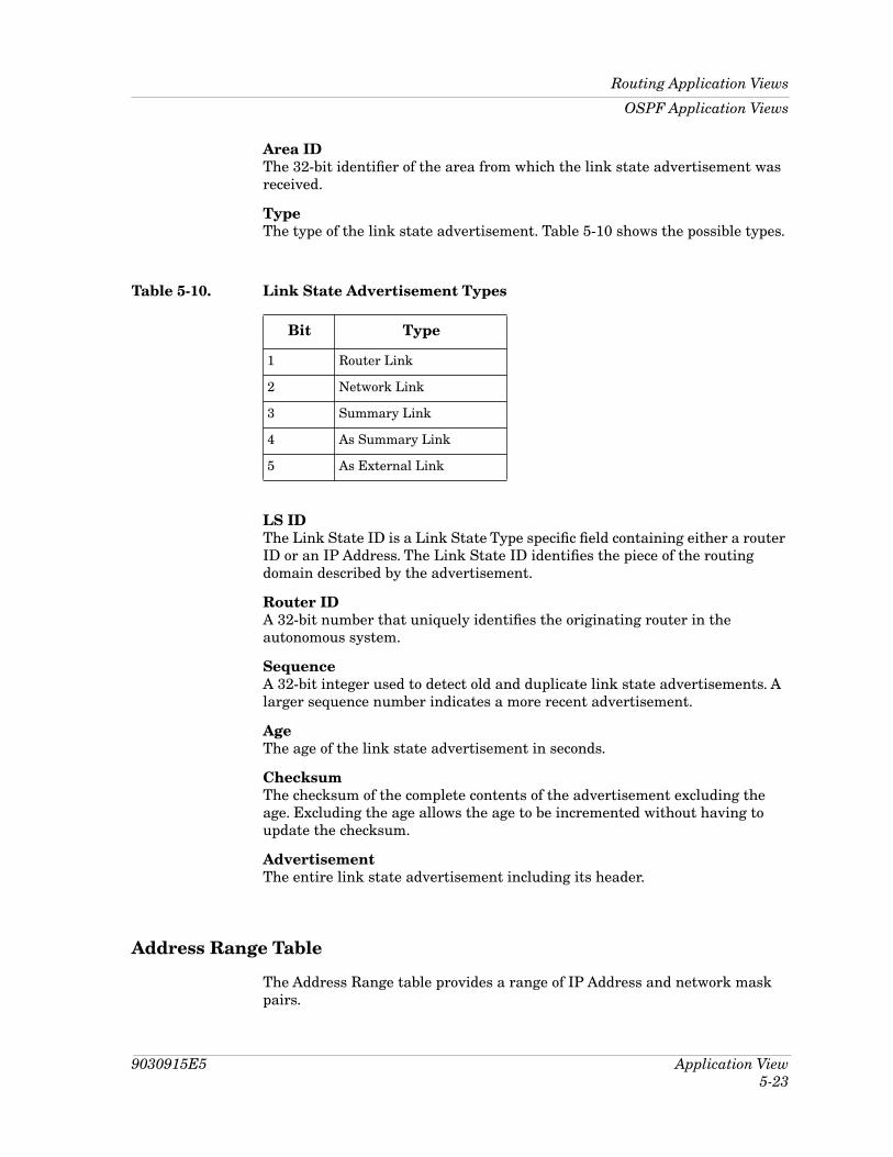
9030915E5 Application View5-23
Routing Application Views
OSPF Application Views
Area IDThe 32-bit identiÞer of the area from which the link state advertisement was received.
TypeThe type of the link state advertisement. Table 5-10 shows the possible types.
LS IDThe Link State ID is a Link State Type speciÞc Þeld containing either a router ID or an IP Address. The Link State ID identiÞes the piece of the routing domain described by the advertisement.
Router IDA 32-bit number that uniquely identiÞes the originating router in the autonomous system.
SequenceA 32-bit integer used to detect old and duplicate link state advertisements. A larger sequence number indicates a more recent advertisement.
AgeThe age of the link state advertisement in seconds.
ChecksumThe checksum of the complete contents of the advertisement excluding the age. Excluding the age allows the age to be incremented without having to update the checksum.
AdvertisementThe entire link state advertisement including its header.
Address Range Table
The Address Range table provides a range of IP Address and network mask pairs.
Table 5-10. Link State Advertisement Types
Bit Type
1 Router Link
2 Network Link
3 Summary Link
4 As Summary Link
5 As External Link

Routing Application ViewsOSPF Application Views
Application View5-24
Proteon IIManagement Module Guide
Area IDThe area in which the address range will be found.
NetworkThe IP Address of the network or subnet indicated by the range.
MaskThe subnet mask that pertains to the network or subnet.
StatusThe status of the Address Range table entry (valid or invalid).
Host Table
The Host table provides information on the hosts that are directly attached to the router and what metrics and types of services should be advertised for them.
IP AddressThe IP Address of the host.
TOSThe type of service (TOS) of the route being conÞgured.
MetricThe metric to be advertised, for a given type of service, when a given host is reachable.
StatusThe status of the Host table entry (valid or invalid).
Interface Table
The Interface table provides the following information speciÞc to the OSPF interfaces.
IP AddressThe IP Address of this OSPF interface.
Address Less IfThis Þeld indicates whether the interface is addressed or addressless. Interfaces with an IP Address display a value of Ò0.Ó Interfaces having no IP Address display that interfaceÕs index.
Area IDA 32-bit integer uniquely identifying the area to which the interface connects. Area ID 0.0.0.0 is used for the OSPF backbone.
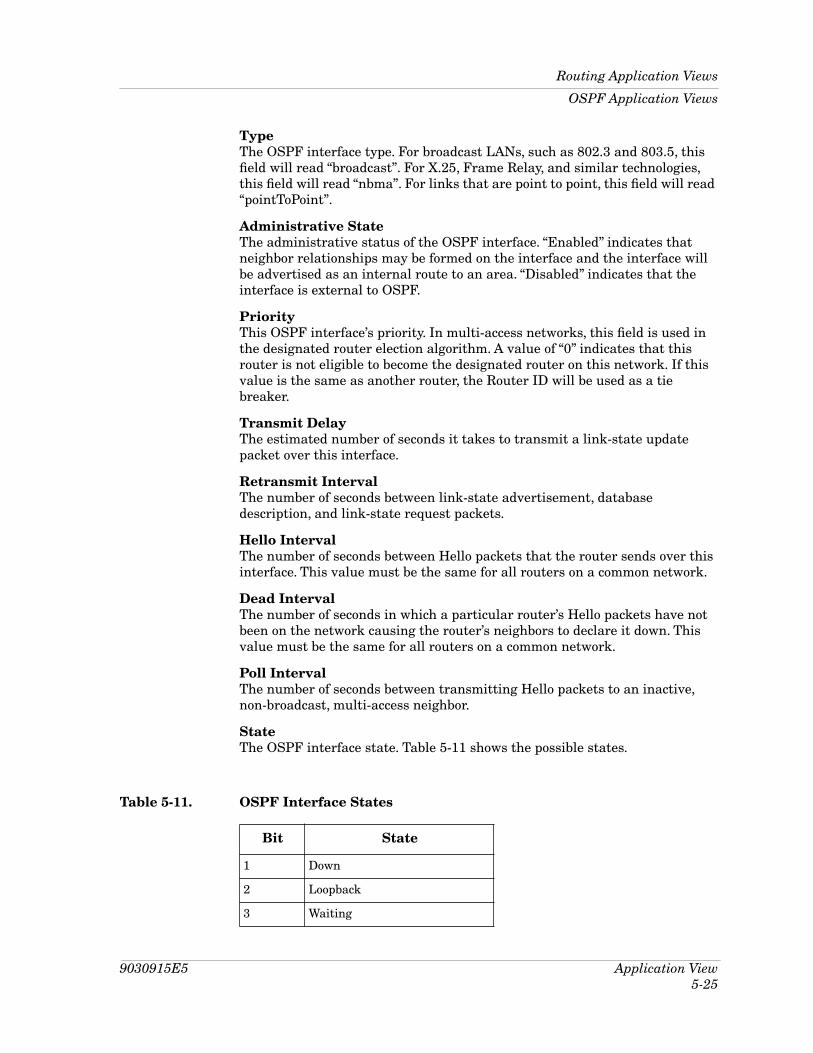
9030915E5 Application View5-25
Routing Application Views
OSPF Application Views
TypeThe OSPF interface type. For broadcast LANs, such as 802.3 and 803.5, this Þeld will read ÒbroadcastÓ. For X.25, Frame Relay, and similar technologies, this Þeld will read ÒnbmaÓ. For links that are point to point, this Þeld will read ÒpointToPointÓ.
Administrative StateThe administrative status of the OSPF interface. ÒEnabledÓ indicates that neighbor relationships may be formed on the interface and the interface will be advertised as an internal route to an area. ÒDisabledÓ indicates that the interface is external to OSPF.
PriorityThis OSPF interfaceÕs priority. In multi-access networks, this Þeld is used in the designated router election algorithm. A value of Ò0Ó indicates that this router is not eligible to become the designated router on this network. If this value is the same as another router, the Router ID will be used as a tie breaker.
Transmit DelayThe estimated number of seconds it takes to transmit a link-state update packet over this interface.
Retransmit IntervalThe number of seconds between link-state advertisement, database description, and link-state request packets.
Hello IntervalThe number of seconds between Hello packets that the router sends over this interface. This value must be the same for all routers on a common network.
Dead IntervalThe number of seconds in which a particular routerÕs Hello packets have not been on the network causing the routerÕs neighbors to declare it down. This value must be the same for all routers on a common network.
Poll IntervalThe number of seconds between transmitting Hello packets to an inactive, non-broadcast, multi-access neighbor.
StateThe OSPF interface state. Table 5-11 shows the possible states.
Table 5-11. OSPF Interface States
Bit State
1 Down
2 Loopback
3 Waiting

Routing Application ViewsOSPF Application Views
Application View5-26
Proteon IIManagement Module Guide
Designated RouterThe IP Address of the designated router.
Backup Designated RouterThe IP Address of the backup designated router.
Events The number of times the OSPF interface has changed its state or an error has occurred.
Interface Metric Table
The Interface Metric table describes the metrics to be advertised for a speciÞed interface at the various types of service.
IP AddressThe IP Address of this OSPF interface.
Address Less IfThis Þeld indicates whether the interface is addressed or addressless. Interfaces with an IP Address display a value of Ò0.Ó Interfaces having no IP Address display that interfaceÕs index.
TOSThe type of service metric being referenced.
StatusThe status of the Interface Metric table entry (valid or invalid).
Virtual Interface Table
The Virtual Interface table provides the following information about the virtual links that the OSPF process is conÞgured to use.
Area IDThe transit area that the virtual link crosses.
4 Point-to-Point
5 Designated Router
6 Backup Designated Router
7 Other Designated Router
Table 5-11. OSPF Interface States (Continued)
Bit State

9030915E5 Application View5-27
Routing Application Views
OSPF Application Views
NeighborThe Router ID of the virtual neighbor.
Transmit DelayThe estimated number of seconds it takes to transmit a link-state update packet over this interface.
Retransmit IntervalThe number of seconds between link-state advertisement, database description, and link-state request packets. This value should be much greater than the expected round trip time.
Hello IntervalThe number of seconds between Hello packets that the router sends over this interface. This value must be the same for the virtual neighbor.
Dead IntervalThe number of seconds in which a particular routerÕs Hello packets have not been on the network causing the routerÕs neighbors to declare it down. This value should be some multiple of the Hello interval and must be the same for the virtual neighbor.
StateThe state of the OSPF virtual interface. Possible states are: down (1) or point-to-point (4).
EventsThe number of times the virtual link has changed its state or an error has occurred.
Authentication KeyThe areaÕs authentication key. If the areaÕs authorization type is a simple password and the key length is shorter than 8 octets, the agent will left justify the Þeld and add zeros until the Þeld reaches 8 octets.
StatusThe status of the Virtual Interface table entry (valid or invalid).
Neighbor Table
The Neighbor table provides the following information about all neighbors in the locality of the router.
IP AddressThe IP Address of this neighbor.
Address Less IfThis Þeld indicates whether the interface is addressed or addressless. Interfaces with an IP Address display a value of Ò0.Ó Interfaces having no IP Address display that interfaceÕs index.

Routing Application ViewsOSPF Application Views
Application View5-28
Proteon IIManagement Module Guide
Router IdA 32-bit integer uniquely identifying the neighboring router in the Autonomous System.
OptionsA bit mask corresponding to the neighborÕs options Þeld.
PriorityThe priority of the neighbor in the designated router election algorithm. A value of Ò0Ó indicates that the neighbor is not eligible to become the designated router on this network.
StateThe state of the relationship with this neighbor. Table 5-12 shows the possible states.
EventsThe number of times this neighbor relationship has changed its state or an error has occurred.
Retransmit QLenThe current length of the retransmission queue.
StatusThe status of the Neighbor table entry (valid or invalid).
Virtual Neighbor Table
The Virtual Neighbor table provides the following information about all virtual neighbors in the locality of the router.
Table 5-12. OSPF Neighbor States
Bit State
1 Down
2 Attempt
3 Init
4 Two Way
5 Exchange Start
6 Exchange
7 Loading
8 Full
9030915E5 Application View5-29
Routing Application Views
OSPF Application Views
Area IDThe transit area identiÞer.
Router IdA 32-bit integer uniquely identifying the neighboring router in the autonomous system.
IP AddressThe IP Address this virtual neighbor is using.
OptionsA bit mask corresponding to the neighborÕs options Þeld.
StateThe state of the relationship with this neighbor. Table 5-12 shows the possible states.
EventsThe number of times this virtual link has changed its state or an error has occurred.
Retransmit QLenThe current length of the retransmission queue.

Routing Application ViewsOSPF Application Views
Application View5-30
Proteon IIManagement Module Guide

9030915E51
IndexAActions 1-1Address Range Table 5-23Alarms View 3-6Application Performance View 5-4Application View 5-11, 5-13Application Views 5-6, 5-16, 5-20Area Metric Table 5-22Area Table 5-21Associations 1-1Attributes 1-1
CComments xivConÞguration View 5-16, 5-20Conventions xii
DDetail View 5-11, 5-19Device
Models 1-1Device ConÞguration View 3-2Diagnostic View 3-6DLM 1-3, 5-1
EEvent Log 3-6Events and Alarms 4-1
FFragmentation View 5-18
GGauge Control Panel 2-10Gauge Mode 2-10Gauge Type 2-12
Generic Routing 5-15Generic Routing Detail View 5-15
HHardware
Requirements xiHelp xivHost Table 5-24
IIF Address Translation 3-6IF Address Translation Table Label 2-7IF ConÞguration View 2-5IF Status View 2-5Inf Description Map 2-10Information View 5-8Interface ConÞguration Table 3-2Interface ConÞguration View
Admin. Status 2-6Bandwidth 2-6Last Change 2-6Max Maintenance Failures 2-6Multi-Bus Interrupt Vector 2-6Next Interface Maintenance 2-6Next Self Test 2-6No. Failed Maintenance Checks 2-6Operation Status 2-5Packet Size 2-6Physical Address 2-6Queue Length 2-6Self Test Failures 2-6Self Test Successes 2-6Status Register Address 2-6Time Between Maint. Checks 2-6Total Maintenance Failures 2-6
Interface Detail View 2-8Interface Icon 2-4Interface Metric Table 5-26

Index2
Proteon IIManagement Module Guide
I (continued)Interface Options Panel 2-9
Find 2-9Interface Description 2-10Network Information 2-10
Interface Status ViewAdministrative Status 2-5Operational Status 2-5
Interface Table 5-24Interface Threshold View 2-9
LLogical Interface Icon 2-4LS Database 5-22
MMAC 5-13Model Type Names 1-1Model Types 1-2
NNeighbor Table 5-27Network Information Panel Label 2-7Network Management xiNotice i
OOSPF 5-20Other Related Documentation xiii
PPerformance View 5-6, 5-11, 5-13, 5-15Performance View Label 2-7Port Status View 5-12Probable Cause Messages 4-1Proteon Ether 5-4Proteon FDDI 5-13Proteon IP 5-16, 5-18, 5-19Proteon IP Address Table 5-17Proteon IP Detail View 5-19Proteon IP Routing 5-16Proteon IP Routing Table 5-17Proteon Router
Applications 1-3Management Information Bases 1-3Model Types 1-2
Proteon Serial 5-11, 5-12Proteon Serial Detail View 5-11Proteon Token Ring 5-6, 5-8
RReassembly View 5-18Related
Hardware Documentation xiiiSPECTRUM Documentation xii
Restricted Rights Notice iiRMON 1-3, 5-1Routing Application Views 5-15
SSMT 5-13SPECTRUM
Documentation xivSPMA
And the Proteon Router 1-3Suggestions xivSupport xiv
TTCP/IP Based Networks xiiiTechnical
Communications xivSupport xiv
Trademarks i
VVirtual Interface Table 5-26Virtual Neighbor Table 5-28Virus Disclaimer i