Protective Device Numbers
24
Protective Device Numbers Protective relays are commonly referred to by standard device numbers. For example, a time overcurrent relay is designated a 51 device, while an instantaneous overcurrent is a 50 device. Multifunction relays have combinations of device numbers. A 27/59 device, for example, is a combination under/over voltage relay. Letters can be added to clarify application (87T for transformer differential, 59G for ground overvoltage). 1 – Master Element 2 – Time Delay Starting or Closing Relay 3 – Checking or Interlocking Relay 4 – Master Contactor 5 – Stopping Device 6 – Starting Circuit Breaker 7 – Rate of Change Relay 8 – Control Power Disconnecting Device 9 – Reversing Device 10 – Unit Sequence Switch 11 – Multi-function Device 12 – Overspeed Device 13 – Synchronous-speed Device 14 – Underspeed Device 15 – Speed – or Frequency, Matching Device 16 – Data Communications Device 17 – Shunting or Discharge Switch 18 – Accelerating or Decelerating Device 19 – Starting to Running Transition Contactor 20 – Electrically Operated Valve 21 – Distance Relay 22 – Equalizer Circuit Breaker 23 – Temperature Control Device 24 – Volts Per Hertz Relay 25 – Synchronizing or Synchronism-Check Device 26 – Apparatus Thermal Device 27 – Undervoltage Relay 28 – Flame detector 29 – Isolating Contactor or Switch 30 – Annunciator Relay 31 – Separate Excitation Device 32 – Directional Power Relay
Transcript of Protective Device Numbers

Protective Device NumbersProtective relays are commonly referred to by standard device numbers. For example, a time overcurrent
relay is designated a 51 device, while an instantaneous overcurrent is a 50 device. Multifunction relays
have combinations of device numbers. A 27/59 device, for example, is a combination under/over voltage
relay. Letters can be added to clarify application (87T for transformer differential, 59G for ground
overvoltage).
1 – Master Element
2 – Time Delay Starting or Closing Relay
3 – Checking or Interlocking Relay
4 – Master Contactor
5 – Stopping Device
6 – Starting Circuit Breaker
7 – Rate of Change Relay
8 – Control Power Disconnecting Device
9 – Reversing Device
10 – Unit Sequence Switch
11 – Multi-function Device
12 – Overspeed Device
13 – Synchronous-speed Device
14 – Underspeed Device
15 – Speed – or Frequency, Matching Device
16 – Data Communications Device
17 – Shunting or Discharge Switch
18 – Accelerating or Decelerating Device
19 – Starting to Running Transition Contactor
20 – Electrically Operated Valve
21 – Distance Relay
22 – Equalizer Circuit Breaker
23 – Temperature Control Device
24 – Volts Per Hertz Relay
25 – Synchronizing or Synchronism-Check Device
26 – Apparatus Thermal Device
27 – Undervoltage Relay
28 – Flame detector
29 – Isolating Contactor or Switch
30 – Annunciator Relay
31 – Separate Excitation Device
32 – Directional Power Relay
33 – Position Switch

34 – Master Sequence Device
35 – Brush-Operating or Slip-Ring Short-Circuiting Device
36 – Polarity or Polarizing Voltage Devices
37 – Undercurrent or Underpower Relay
38 – Bearing Protective Device
39 – Mechanical Condition Monitor
40 – Field (over/under excitation) Relay
41 – Field Circuit Breaker
42 – Running Circuit Breaker
43 – Manual Transfer or Selector Device
44 – Unit Sequence Starting Relay
45 – Abnormal Atmospheric Condition Monitor
46 – Reverse-phase or Phase-Balance Current Relay
47 – Phase-Sequence or Phase-Balance Voltage Relay
48 – Incomplete Sequence Relay
49 – Machine or Transformer, Thermal Relay
50 – Instantaneous Overcurrent Relay
51 – AC Inverse Time Overcurrent Relay
52 – AC Circuit Breaker
53 – Exciter or DC Generator Relay
54 – Turning Gear Engaging Device
55 – Power Factor Relay
56 – Field Application Relay
57 – Short-Circuiting or Grounding Device
58 – Rectification Failure Relay
59 – Overvoltage Relay
60 – Voltage or Current Balance Relay
61 – Density Switch or Sensor
62 – Time-Delay Stopping or Opening Relay
63 – Pressure Switch
64 – Ground Detector Relay
65 – Governor
66 – Notching or Jogging Device
67 – AC Directional Overcurrent Relay
68 – Blocking or "Out-of-Step" Relay
69 – Permissive Control Device
70 – Rheostat
71 – Liquid Level Switch
72 – DC Circuit Breaker
73 – Load-Resistor Contactor
74 – Alarm Relay

75 – Position Changing Mechanism
76 – DC Overcurrent Relay
77 – Telemetering Device
78 – Phase-Angle Measuring Relay
79 – AC Reclosing Relay
80 – Flow Switch
81 – Frequency Relay
82 – DC Reclosing Relay
83 – Automatic Selective Control or Transfer Relay
84 – Operating Mechanism
85 – Communications,Carrier or Pilot-Wire Relay
86 – Lockout Relay
87 – Differential Protective Relay
88 – Auxiliary Motor or Motor Generator
89 – Line Switch
90 – Regulating Device
91 – Voltage Directional Relay
92 – Voltage and Power Directional Relay
93 – Field Changing Contactor
94 – Tripping or Trip-Free Relay
95 to 99 – For specific applications where other numbers are not suitable
* for a full definition of each function, please refer to the ANSI/IEEE C37.2 standard
Prefixes and SuffixesLetters and numbers may be used as prefixes or suffixes to device function numbers to provide a more
specific definition of the function. Prefixes and suffixes should, however, be used only when they
accomplish a useful purpose.
Auxiliary devices
C - Closing relay/contactor
CL - Auxiliary relay, closed
CS - Control switch
D - "Down" position switch relay
L- Lowering relay
O - Opening relay/contactor
OP - Auxiliary relay, open
PB - Push button
R - Raising relay
U - "UP" position switch relay
X - Auxiliary relay
Y - Auxiliary relay
Main device
A - Alarm/auxiliary power
AC - Alternating current
AN - Anode
B - Battery, blower, bus
BK - Brake
BL - Block (valve)
BP - Bypass
BT - Bus tie
C - Capacitor, condenser,
compensator, carrier current, case,
compressor
CA - Cathode

Z - Auxiliary relay
Actuating quantities
A -Air/amperes/alternating
C - Current
D - Direct/discharge
E - Electrolyte
F - Frequency/flow/fault
GP - Gas pressure
H - Explosive/harmonics
I0 - Zero sequence current
I-, I2 - Negative sequence current
I+, I1 - Positive sequence current
J - Differential
L - Level/liquid
P - Power/pressure
PF - Power factor
Q - Oil
S - Speed/suction/smoke
T - Temperature
V - Voltage/volts/vacuum
VAR -Reactive power
VB - Vibration
W - ater/watts
Other suffix letters
A - Accelerating, automatic
B - Blocking, backup
BF - Breaker failure
C - Close, cold
D - Decelerating, detonate, down,
disengaged
E - Emergency, engaged
F - Failure, forward
GP - General purpose
H - Hot, high
HIZ - High impedance fault
HR - Hand reset
HS - High speed
CH - Check (valve)
D - Discharge (valve)
DC - Direct current
E - Exciter
F - Feeder, field, filament, filter, fan
G - Generator/ground
H - Heater/housing
L - Line, logic
M - Motor, metering
MOC - Mechanism operated contact
N - Network, neutral
P - Pump, phase comparison
R - Reactor, rectifier, room
S - Synchronizing, secondary,
strainer, sump ,suction (valve)
T -Transformer, thyratron
TH - Transformer (high-voltage side)
TL - Transformer (low-voltage side)
TM - Telemeter
TOC - Truck-operated contacts
TT - Transformer (tertiary-voltage
side)
U - Unit
Main device parts
BK - Brake
C - Coil, condenser, capacitor
CC - Closing coil, closing contactor
HC - Holding coil
M - Operating motor
MF - Fly-ball motor
ML - Load-limit motor
MS - Speed adjusting or synchronizing
motor
OC - Opening contactor
S - Solenoid
SI - Seal-in
T - Target
TC Trip coil
V - Valve

L - Left, local, low, lower, leading
M - Manual
O - Open, over
OFF - Off
ON - On
P - Polarizing
R - Right, raise, reclosing, receiving,
remote, reverse
S - Sending, swing
SHS - Semi-high speed
T - Test, trip, trailing
TDC - Time-delay closing contact
TDDO - Time delayed relay coil drop-out
TDO - Time-delay opening contact
TDPU - Time delayed relay coil pickup
THD - Total harmonic distortion
U - Up, under
Reference positions of devices
Adjusting means - Low or down
position
Clutch - Disengaged position
Contactor - De-energized position
Contactor (latched-in type) - Main
contacts open
Density switch - Standard reference
Disconnecting switch - Main contacts
open
Flow detector - Lowest flow
Gate - Closed position
Level detector - Lowest level
Load-break switch - Main contacts
open
Power circuit breaker - Main contacts
open
Power electrodes - Maximum gap
position
Pressure switch - Lowest pressure
Reclosure - Main contactor open
Relay - De-energized position
Relay (latched-in type)
Rheostat - Maximum resistance
position
Speed switch - Lowest speed
Tap changer - Center tap
Temperature relay - Lowest
temperature
Turning gear - Disengaged position
Vacuum switch - Lowest pressure that
is highest vacuum
Valve - Closed position
Vibration detector - Minimum
vibration
ANSI IEC ComparisonANSI IEC 60617 Description

21FL FLOC Fault locator
21G Z< Underimpedance
24 U/f> Overexcitation
25 SYNC Synchronisation check
27 U< Undervoltage
32 P→ Directional power relay
32P, P→, - active power
32Q, Q→ - reactive powerpower
37 I< Non-directional undercurrent
40 X< Underexcitation
46 I2> Negative-phase sequence
47 U2> Phase-sequence voltage protection
48, 14, 66 Is²t,n< Start-up supervision for motors
49F Ith> Thermal protection for cables
49M/49G/49T Three-phase thermal protection for machines
M - motor, G - generators, T - transformer
50N/51N I0> Non-directional earth-fault
51 I> Non-directional overcurrent
51C, I> - shunt capacitors
51V, I(U)> - voltage dependant
59 U> Overvoltage
59N, U0> - residual overvoltage
67 I>→ Directional overcurrent
67N, I0>→ - directional earth-fault
68 I2> Transformer/motor inrush current
79 0→1 Auto-reclosure
81 f Frequency relay
81N, f< - underfrquency
81O, f> - overfrequency
87 ΔI> Differential protection
87G, ΔI> - generator
87M, ΔI> - motor

87T, ΔI> - transformer
87N, ΔI0> - restricted earth fault
Notes:
1. for high set and instantaneous tripping, '>' can be replaced with '>>' or '>>'
2. '3' can be placed before designations to indicate three phase, i.e. 3I<- See more at: http://myelectrical.com/notes/entryid/148/ansi-ieee-protective-device-numbering#sthash.pqTpwukA.dpuf
Posted by ecsanyi on Wednesday, April 14, 2010 at 10:23 pm | Technical Articles | Categories | Submit Article
ANSI/IEC Relay Symbols55,700 views
There are two methods for indicating protection relay functions in common use. One is given in ANSI Standard C37-
2, and uses a numbering system for various functions. The functions are supplemented by letters where amplification
of the function is required. The other is given in IEC 60617, and uses graphical symbols. To assist the Protection
Engineer in converting from one system to the other, a select list of ANSI device numbers and their IEC equivalents is
given in Figure A2.1.

Posted by ecsanyi on Monday, September 14, 2009 at 11:29 pm | Technical Articles | Categories | Submit Article
Protection relays – important informations14,574 views
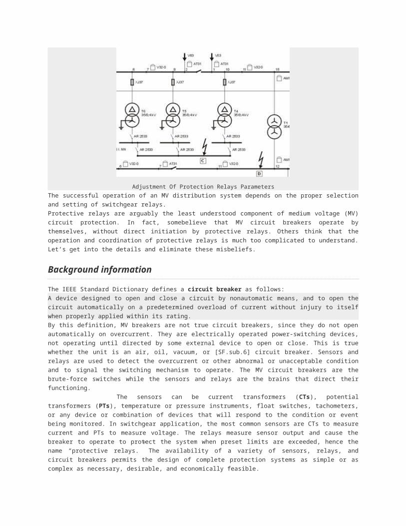
Adjustment Of Protection Relays Parameters
The successful operation of an MV distribution system depends on the proper selection and setting of switchgear
relays.
Protective relays are arguably the least understood component of medium voltage (MV) circuit protection. In fact,
somebelieve that MV circuit breakers operate by themselves, without direct initiation by protective relays. Others think
that the operation and coordination of protective relays is much too complicated to understand. Let’s get into the
details and eliminate these misbeliefs.
Background information
The IEEE Standard Dictionary defines a circuit breaker as follows:
A device designed to open and close a circuit by nonautomatic means, and to open the circuit automatically on a
predetermined overload of current without injury to itself when properly applied within its rating.
By this definition, MV breakers are not true circuit breakers, since they do not open automatically on overcurrent.
They are electrically operated power-switching devices, not operating until directed by some external device to open
or close. This is true whether the unit is an air, oil, vacuum, or [SF.sub.6] circuit breaker. Sensors and relays are used
to detect the overcurrent or other abnormal or unacceptable condition and to signal the switching mechanism to
operate. The MV circuit breakers are the brute-force switches while the sensors and relays are the brains that direct
their functioning.
The sensors can be current transformers (CTs), potential transformers (PTs), temperature
or pressure instruments, float switches, tachometers, or any device or combination of devices that will respond to the
condition or event being monitored. In switchgear application, the most common sensors are CTs to measure current
and PTs to measure voltage. The relays measure sensor output and cause the breaker to operate to protect the
system when preset limits are exceeded, hence the name “protective relays.” The availability of a variety of sensors,
relays, and circuit breakers permits the design of complete protection systems as simple or as complex as necessary,
desirable, and economically feasible.

Electromechanical relays
Electromechanical relay
For many years, protective relays have been electromechanical devices, built like fine watches, with great precision
and often with jeweled bearings. They have earned a well-deserved reputation for accuracy, dependability, and
reliability. There are two basic types of operating mechanisms: the electromagnetic-attraction relay and the
electromagnetic-induction relay.
Magnetic attraction relays. Magnetic-attraction relays, have either a solenoid that pulls in a plunger, or one or more
electromagnets that attract a hinged armature. When the magnetic force is sufficient to overcome the restraining
spring, the movable element begins to travel, and continues until the contact(s) close or the magnetic force is
removed. The pickup point is the current or voltage at which the plunger or armature begins to move and, in a
switchgear relay, the pickup value can be set very precisely.
These relays are usually instantaneous in action, with no intentional time delay, closing as soon after pickup as the
mechanical motion permits. Time delay can be added to this type of relay by means of a bellows, dashpot, or a
clockwork escapement mechanism. However, timing accuracy is considerably less precise than that of induction-type
relays, and these relays are seldom used with time delay in switchgear applications.
Attraction-type relays can operate with either AC or DC on the coils; therefore, relays using this principle are affected
by the DC component of an asymmetrical fault and must be set to allow for this.
Induction relays. Induction relays, are available in many variations to provide accurate pickup and time-current
responses for a wide range of simple or complex system conditions. Induction relays are basically induction motors.
The moving element, or rotor, is usually a metal disk, although it sometimes may be a metal cylinder or cup. The
stator is one or more electromagnets with current or potential coils that induce currents in the disk, causing it to
rotate. The disk motion is restrained by a spring until the rotational forces are sufficient to turn the disk and bring its
moving contact against the stationary contact, thus closing the circuit the relay is controlling. The greater the fault
being sensed, the greater the current in the coils, and the faster the disk rotates.
A calibrated adjustment, called the time dial, sets the spacing between the moving and stationary contacts to vary the
operating time of the relay from fast (contacts only slightly open) to slow (contacts nearly a full disk revolution apart).
Reset action begins when the rotational force is removed, either by closing the relay contact that trips a breaker or by
otherwise removing the malfunction that the relay is sensing. The restraining spring resets the disk to its original
position. The time required to reset depends on the type of relay and the time-dial setting (contact spacing).
With multiple magnetic coils, several conditions of voltage and current can be sensed simultaneously. Their signals
can be additive or subtractive in actuating the disk. For example, a current-differential relay has two current coils with
opposing action. If the two currents are equal, regardless of magnitude, the disk does not move. If the difference
between the two currents exceeds the pickup setting, the disk rotates slowly for a small difference and faster for a
greater difference. The relay contacts close when the difference continues for the length of time determined by the
relay characteristics and settings. Using multiple coils, directional relays can sense direction of current or power flow,
as well as magnitude. Since the movement of the disk is created by induced magnetic fields from AC magnets,
induction relays are almost completely unresponsive to the DC component of an asymmetrical fault.
Most switchgear-type relays are enclosed in a semiflush-mounting drawout case. Relays usually are installed on the
door of the switchgear cubicle. Sensor and control wiring are brought to connections on the case. The relay is

inserted into the case and connected by means of small switches or abridging plug, depending on the manufacturer.
It can be disconnected and withdrawn from the case without disturbing the wiring. When the relay is disconnected,
the CT connections in the case are automatically shorted to short circuit the CT secondary winding and protect the
CT from overvoltages and damage.
Many relays are equipped with a connection for a test cable. This permits using a test set to check the relay
calibration. The front cover of the relay is transparent, can be removed for access to the mechanism, and has
provisions for wire and lead seals to prevent tampering by unauthorized personnel.
Solid-state relays
Solid state relay
Recently, solid-state electronic relays have become more popular. These relays can perform all the functions that can
be performed by electromechanical relays and, because of the versatility of electronic circuitry and microprocessors,
can provide many functions not previously available. In general, solid-state relays are smaller and more compact than
their mechanical equivalents. For example, a 3-phase solid-state overcurrent relay can be used in place of three
single-phase mechanical overcurrent relays, yet is smaller than one of them.
The precision of electronic relays is greater than that of mechanical relays, allowing closer system coordination. In
addition, because there is no mechanical motion and the electronic circuitry is very stable, they retain their calibration
accuracy for a long time. Reset times can be extremely short if desired because there is no mechanical motion.
Electronic relays require less power to operate than their mechanical equivalents, producing a smaller load burden on
the CTs and PTs that supply them. Because solid-state relays have a minimum of moving parts, they can be made
very resistant to seismic forces and are therefore especially well suited for areas susceptible to earthquake activity.
In their early versions, some solid-state relays were sensitive to the severe electrical environment of industrial
applications. They were prone to failure, especially from high transient voltages caused by lightning or utility and on-
site switching. However, today’s relays have been designed to withstand these transients and other rugged
application conditions, and this type of failure has essentially been eliminated. Solid-state relays have gained a strong
and rapidly growing position in the marketplace as experience proves their accuracy, dependability, versatility, and
reliability.
The information that follows applies to electromechanical and solid-state relays, although one functions mechanically
and the other electronically. Significant differences will be pointed out.
Relay types
There are literally hundreds of different types of relays. The catalog of one manufacturer of electromechanical relays
lists 264 relays for switchgear and system protection and control functions. For complex systems with many voltage
levels and interconnections over great distances, such as utility transmission and distribution, relaying is an art to
which some engineers devote their entire careers. For more simple industrial and commercial distribution, relay
protection can be less elaborate, although proper selection and application are still very important.

The most commonly used relays and devices are listed HERE in the Table by their American National Standards
Institute (ANSI) device-function number and description. These standard numbers are used in one-line and
connection diagrams to designate the relays or other devices, saving space and text.
Where a relay combines two functions, the function numbers for both are shown. The most frequently used relay is
the overcurrent relay, combining both instantaneous and inverse-time tripping functions. This is designated device
50/51. As another example, device 27/59 would be a combined undervoltage and overvoltage relay. The complete
ANSI standard lists 99 device numbers, a few of which are reserved for future use.
Relays can be classified by their operating-time characteristics. Instantaneous relays are those with no intentional
time delay. Some can operate in one-half cycle or less; others may take as long as six cycles. Relays that operate in
three cycles or less are called high-speed relays.
Time-delay relays can be definite-time or inverse-time types. Definite-time relays have a preset time delay that is not
dependent on the magnitude of the actuating signal (current, voltage, or whatever else is being sensed) once the
pickup value is exceeded. The actual preset time delay is usually adjustable.
Inverse-time relays, such as overcurrent or differential relays, have operating times that do depend on the value of
actuating signal. The time delay is long for small signals and becomes progressively shorter as the value of the signal
increases. The operating time is inversely proportional to the magnitude of the event being monitored.
Overcurrent relays
Sepam protection relay
In switchgear application, an overcurrent relay usually is used on each phase of each circuit breaker and often one
additional overcurrent relay is used for ground-fault protection. Conventional practice is to use one instantaneous
short-circuit element and one inverse-time overcurrent element (ANSI 50/51) for each phase.
In the standard electromechanical relay, both elements for one phase are combined in one relay case. The
instantaneous element is a clapper or solenoid type and the inverse-time element is an induction-disk type.
In some solid-state relays, three instantaneous and three inverse-time elements can be combined in a single relay
case smaller than that of one induction-disk relay.
Overcurrent relays respond only to current magnitude, not to direction of current flow or to voltage. Most relays are
designed to operate from the output of a standard ratio-type CT, with 5A secondary current at rated primary current.
A solid-state relay needs no additional power supply, obtaining the power for its electronic circuitry from the output of
the CT supplying the relay.
On the instantaneous element, only the pickup point can be set, which is the value of current at which the
instantaneous element will act, with no intentional time delay, to close the trip circuit of the circuit breaker. The actual
time required will decrease slightly as the magnitude of the current increases, from about 0.02 sec maximum to about
0.006 sec minimum, as seen from the instantaneous curve. This time will vary with relays of different ratings or
manufacturers and also will vary between electromechanical and solid-state relays.
Time delays can be selected over a wide range for almost any conceivable requirement. Time-delay selection starts
with the choice of relay. There are three time classifications: standard, medium, and long time delay. Within each
classification, there are three classes of inverse-time curve slopes: inverse (least steep), very inverse (steeper), and

extremely inverse (steepest). The time classification and curve slopes are characteristic of the relay selected,
although for some solid-state relays these may be adjustable to some degree. For each set of curves determined by
the relay selection, the actual response is adjustable by means of the time dial.
On the inverse-time element, there are two settings. First the pickup point is set. This is the value of current at which
the timing process begins as the disk begins to rotate on an electromechanical relay or the electronic circuit begins to
time out on a solid-state relay.
Next the time-dial setting is selected. This adjusts the time-delay curve between minimum and maximum curves for
the particular relay. A given relay will have only one set of curves, either inverse, very inverse, or extremely inverse,
adjustable through the full time-dial range. Note that the current is given in multiples of pickup setting.
Each element, instantaneous or time delay, has a flag that indicates when that element has operated. This flag must
be reset manually after relay operation.
Setting the pickup point
The standard overcurrent relay is designed to operate from a ratio-type CT with a standard 5A secondary output. The
output of the standard CT is 5A at the rated nameplate primary current, and the output is proportional to the primary
current over a wide range. For example, a 100/5 ratio CT would have a 5A output when the primary current (the
current being sensed and measured) is 100A. This primary-to-secondary ratio of 20-to-1 is constant so that for a
primary current of 10A, the secondary current would 0.5A; for 20A primary, 1.0A secondary; for 50A primary, 2.5A
secondary; etc. For 1000A primary, the secondary current is 50A, and similarly for all values of current up to the
maximum that the CT will handle before it saturates and becomes nonlinear.
The first step in setting the relay is selecting the CT so that the pickup can be set for the desired primary current
value. The primary current rating should be such that a primary current of 110 to 125% of the expected maximum
load will produce the rated 5A secondary current. The maximum available primary fault current should not produce
more than 100A secondary current to avoid saturation and excess heating. It may not be possible to fulfill these
requirements exactly, but they are useful guidelines. As a result, some compromise may be necessary.
On the 50/51 overcurrent relay, the time-overcurrent-element (device 51) setting is made by means of a plug or screw
inserted into the proper hole in a receptacle with a number of holes marked in CT secondary amperes, by an
adjustable calibrated lever or by some similar method. This selects one secondary current tap (the total number of
taps depends on the relay) on the pickup coil. The primary current range of the settings is determined by the ratio of
the CT selected.
For example, assume that the CT has a ratio of 50/5A. Typical taps will be 4, 5, 6, 7, 8, 10, 12, and 16A. The pickup
settings would range from a primary current of 40A (the 4A tap) to 160A (the 16A tap). If a 60A pickup is desired, the
6A tap is selected. If a pickup of more than 160A or less than 40A is required, it would be necessary to select a CT
with a different ratio or, in some cases, a different relay with higher or lower tap settings.
Various types of relays are available with pickup coils rated as low as 1.5A and as high as 40A. Common coil ranges
are 0.5 to 2A, for low-current pickup such as ground-fault sensing; 1.5 to 6A medium range; or 4 to 16A, the range
usually chosen for overcurrent protection. CTs are available having a wide range of primary ratings, with standard 5A
secondaries or with other secondary ratings, tapped secondaries, or multiple secondaries.
A usable combination of CT ratio and pickup coil can be found for almost any desired primary pickup current and
relay setting.
The instantaneous trip (device 50) setting is also adjustable. The setting is in pickup amperes, completely
independent of the pickup setting of the inverse-time element or, on some solid-state relays, in multiples of the
inverse-time pickup point. For example, one electromechanical relay is adjustable from 2 to 48A pickup; a solid-state
relay is adjustable from 2 to 12 times the setting of the inverse-time pickup tap. On most electromechanical relays,
the adjusting means is a tap plug similar to that for the inverse-time element. With the tap plug, it is possible to select
a gross current range. An uncalibrated screw adjustment provides final pickup setting. This requires using a test set

to inject calibration current into the coil if the setting is to be precise. On solid-state relays, the adjustment may be a
calibrated switch that can be set with a screwdriver.
Setting the time dial
For any given tap or pickup setting, the relay has a whole family of time-current curves. The desired curve is selected
by rotating a dial or moving a lever. The time dial or lever is calibrated in arbitrary numbers, between minimum and
maximum values, as shown on curves published by the relay manufacturer. At a time-dial setting of zero, the relay
contacts are closed. As the time dial setting is increased, the contact opening becomes greater, increasing relay
operating time. Settings may be made between calibration points, if desired, and the applicable curve can be
interpolated between the printed curves.
The pickup points and time-dial settings are selected so that the relay can perform its desired protective function. For
an overcurrent relay, the goal is that when a fault occurs on the system, the relay nearest the fault should operate.
The time settings on upstream relays should delay their operation until the proper overcurrent device has cleared the
fault. A selectivity study, plotting the time-current characteristics of every device in that part of the system being
examined, is required. With the wide selection of relays available and the flexibility of settings for each relay, selective
coordination is possible for most systems.
Selecting and setting other than overcurrent relays are done in similar fashion. Details will vary, depending on the
type of relay, its function in the system, and the relay manufacturer.
Relay operation
An electromechanical relay will pick up and start to close its contacts when the current reaches the pickup value. At
the inverse-time pickup current, the operating forces are very low and timing accuracy is poor. The relay timing is
accurate at about 1.5 times pickup or more, and this is where the time-current curves start. This fact must be
considered when selecting and setting the relay.
When the relay contacts close, they can bounce, opening slightly and creating an arc that will burn and erode the
contact surfaces. To prevent this, overcurrent relays have an integral auxiliary relay with a seal-in contact in parallel
with the timing relay contacts that closes immediately when the relay contacts touch. This prevents arcing if the relay
contacts bounce. This auxiliary relay also activates the mechanical flag that indicates that the relay has operated.
When the circuit breaker being controlled by the relay opens, the relay coil is deenergized by an auxiliary contact on
the breaker. This protects the relay contacts, which are rated to make currents up to 30A but should not break the
inductive current of the breaker tripping circuit, to prevent arcing wear. The disk is then returned to its initial position
by the spring. The relay is reset. Reset time is the time required to return the contacts fully to their original position.
Contacts part about 0.1 sec (six cycles) after the coil is deenergized. The total reset time varies with the relay type
and the time-dial setting. For a maximum time-dial setting (contacts fully open), typical reset times might be 6 sec for
an inverse-time relay and up to 60 sec for a very inverse or extremely inverse relay. At lower time-dial settings,
contact opening distance is less, therefore reset time is lower.
A solid-state relay is not dependent on mechanical forces or moving contacts for its operation but performs its
functions electronically. Therefore, the timing can be very accurate even for currents as low as the pickup value.
There is no mechanical contact bounce or arcing, and reset times can be extremely short.

CT and PT selection
MV current transformer
In selecting instrument transformers for relaying and metering, a number of factors must be considered; transformer
ratio, burden, accuracy class, and ability to withstand available fault currents.
CT ratio. CT guidelines mentioned earlier are to have rated secondary output at 110 to 125% of expected load and no
more than 100A secondary current at maximum primary fault current. Where more than one CT ratio may be
required, CTs with tapped secondary windings or multi-winding secondaries are available.
CT burden. CT burden is the maximum secondary load permitted, expressed in voltamperes (VA) or ohms
impedance, to ensure accuracy. ANSI standards list burdens of 2.5 to 45VA at 90% power factor (PF) for metering
CTs, and 25 to 200VA at 50% PF for relaying CTs.
CT accuracy class. ANSI accuracy class standards are [+ or -] 0.3, 0.6, or 1.2%. Ratio errors occur because of
[I.sup.2]R heating losses. Phase-angle errors occur because of magnetizing core losses.
CTs are marked with a dot or other polarity identification on primary and secondary windings so that at the instant
current is entering the marked primary terminal it is leaving the marked secondary terminal. Polarity is not required for
overcurrent sensing but is important for differential relaying and many other relaying functions.
PT ratio. PT ratio selection is relatively simple. The PT should have a ratio so that, at the rated primary voltage, the
secondary output is 120V. At voltages more than 10% above the rated primary voltage, the PT will be subject to core
saturation, producing voltage errors and excess heating.
PT burden. PTs are available for burdens from 12.5VA at 10% PF to as high as 400VA at 85% PF.
PT accuracy. Accuracy classes are ANSI standard [+ or -] 0.3, 0.6, or 1.2%. PT primary circuits, and where feasible
PT secondary circuits as well, should be fused.
CTs and PTs should have adequate capacity for the burden to be served and sufficient accuracy for the functions
they are to perform. However, more burden or accuracy than necessary will merely increase the cost of the metering
transformers. Solid-state relays usually impose lower burdens than electromechanical relays.
Izvor: www.ecmweb.com
Posted by ecsanyi on Sunday, September 13, 2009 at 4:13 pm | Technical Articles | Categories | Submit Article
ANSI standards for protection devices51,424 views

ANSI Functions For Protection Devices
In the design of electrical power systems, the ANSI Standard Device Numbers denote what features a protective
device supports (such as a relay or circuit breaker). These types of devices protect electrical systems and
components from damage when an unwanted event occurs, such as an electrical fault.
ANSI numbers are used to identify the functions of meduim voltage microprocessor devices.
ANSI facilitates the development of American National Standards (ANS) by accrediting the procedures of standards
developing organizations (SDOs). These groups work cooperatively to develop voluntary national consensus
standards. Accreditation by ANSI signifies that the procedures used by the standards body in connection with the
development of American National Standards meet the Institute’s essential requirements for openness, balance,
consensus and due process.
ANSI standards (protection) – index
Current protection functions Recloser
ANSI 50/51 – Phase overcurrent ANSI 79 – Reclose the circuit breaker after tripping
ANSI 50N/51N or 50G/51G – Earth fault or sensitive earth fault
Directional current protection
ANSI 50BF – Breaker failure ANSI 67 – Directional phase overcurrent
ANSI 46 -Negative sequence / unbalance ANSI 67N/67NC – Directional earth fault
ANSI 49RMS – Thermal overload ANSI 67N/67NC type 1
Directional power protection functions ANSI 67N/67NC type 2
ANSI 32P – Directional active overpower ANSI 67N/67NC type 3
ANSI 32Q/40 – Directional reactive overpower
Machine protection functions
Voltage protection functions ANSI 37 – Phase undercurrent
ANSI 27D – Positive sequence undervoltage ANSI 48/51LR/14 – Locked rotor / excessive
starting time
ANSI 27R – Remanent undervoltage ANSI 66 – Starts per hour
ANSI 27 – Phase-to-phase undervoltage ANSI 50V/51V – Voltage-restrained overcurrent
ANSI 59 – Phase-to-phase overvoltageANSI 26/63 – Thermostat, Buchholz, gas, pressure,
temperature detection
ANSI 59N – Neutral voltage displacement ANSI 38/49T – Temperature monitoring by RTD
ANSI 47 – Negative sequence voltage Frequency protection functions
ANSI 81H – Overfrequency
ANSI 81L – Underfrequency
ANSI 81R – Rate of change of frequency (ROCOF)
Current protection functions
ANSI 50/51 – Phase overcurrent
Three-phase protection against overloads and phase-to-phase short-circuits.
ANSI index ↑
ANSI 50N/51N or 50G/51G – Earth fault
Earth fault protection based on measured or calculated residual current values:
ANSI 50N/51N: residual current calculated or measured by 3 phase current sensors
ANSI 50G/51G: residual current measured directly by a specific sensor
ANSI index ↑
ANSI 50BF – Breaker failure
If a breaker fails to be triggered by a tripping order, as detected by the non-extinction of the fault current, this backup
protection sends a tripping order to the upstream or adjacent breakers.
ANSI index ↑
ANSI 46 – Negative sequence / unbalance
Protection against phase unbalance, detected by the measurement of negative sequence current:
sensitive protection to detect 2-phase faults at the ends of long lines
protection of equipment against temperature build-up, caused by an unbalanced power supply, phase inversion
or loss of phase, and against phase current unbalance
ANSI index ↑

ANSI 49RMS – Thermal overload
Protection against thermal damage caused by overloads on machines (transformers, motors or generators).
The thermal capacity used is calculated according to a mathematical model which takes into account:
current RMS values
ambient temperature
negative sequence current, a cause of motor rotor temperature rise
ANSI index ↑
Recloser
ANSI 79
Automation device used to limit down time after tripping due to transient or semipermanent faults on overhead lines.
The recloser orders automatic reclosing of the breaking device after the time delay required to restore the insulation
has elapsed. Recloser operation is easy to adapt for different operating modes by parameter setting.
ANSI index ↑
Directional current protection
ANSI 67N/67NC type 1
ANSI 67 – Directional phase overcurrent
Phase-to-phase short-circuit protection, with selective tripping according to fault current direction. It comprises a
phase overcurrent function associated with direction detection, and picks up if the phase overcurrent function in the
chosen direction (line or busbar) is activated for at least one of the 3 phases.
ANSI index ↑
ANSI 67N/67NC – Directional earth fault
Earth fault protection, with selective tripping according to fault current direction.
3 types of operation:
type 1: the protection function uses the projection of the I0 vector
type 2: the protection function uses the I0 vector magnitude with half-plane tripping zone
type 3: the protection function uses the I0 vector magnitude with angular sector tripping zone
ANSI index ↑
ANSI 67N/67NC type 1
Directional earth fault protection for impedant, isolated or compensated neutralsystems, based on the projection of
measured residual current.
ANSI index ↑
ANSI 67N/67NC type 2
Directional overcurrent protection for impedance and solidly earthed systems, based on measured or calculated
residual current. It comprises an earth fault function associated with direction detection, and picks up if the earth fault

function in the chosen direction (line or busbar) is activated.
ANSI index ↑
ANSI 67N/67NC type 3
Directional overcurrent protection for distribution networks in which the neutral earthing system varies according to
the operating mode, based on measured residual current. It comprises an earth fault function associated with
direction detection (angular sector tripping zone defined by 2 adjustable angles), and picks up if the earth fault
function in the chosen direction (line or busbar) is activated.
ANSI index ↑
Directional power protection functions
ANSI 32P – Directional active overpower
Two-way protection based on calculated active power, for the following applications:
active overpower protection to detect overloads and allow load shedding
reverse active power protection:
against generators running like motors when the generators consume active power
against motors running like generators when the motors supply active power
ANSI index ↑
ANSI 32Q/40 – Directional reactive overpower
Two-way protection based on calculated reactive power to detect field loss on synchronous machines:
reactive overpower protection for motors which consume more reactive power with field loss
reverse reactive overpower protection for generators which consume reactive power with field loss.
ANSI index ↑
Machine protection functions
ANSI 37 – Phase undercurrent
Protection of pumps against the consequences of a loss of priming by the detection of motor no-load operation.
It is sensitive to a minimum of current in phase 1, remains stable during breaker tripping and may be inhibited by a
logic input.
ANSI index ↑
ANSI 48/51LR/14 – Locked rotor / excessive starting time
Protection of motors against overheating caused by:
excessive motor starting time due to overloads (e.g. conveyor) or insufficient supply voltage.
The reacceleration of a motor that is not shut down, indicated by a logic input, may be considered as starting.
locked rotor due to motor load (e.g. crusher):
in normal operation, after a normal start
directly upon starting, before the detection of excessive starting time, with detection of locked rotor by a zero
speed detector connected to a logic input, or by the underspeed function.
ANSI index ↑

ANSI 66 – Starts per hour
Protection against motor overheating caused by:
too frequent starts: motor energizing is inhibited when the maximum allowable number of starts is reached, after
counting of:
starts per hour (or adjustable period)
consecutive motor hot or cold starts (reacceleration of a motor that is not shut down, indicated by a logic
input, may be counted as a start)
starts too close together in time: motor re-energizing after a shutdown is only allowed after an adjustable waiting
time.
ANSI index ↑
ANSI 50V/51V – Voltage-restrained overcurrent
Phase-to-phase short-circuit protection, for generators. The current tripping set point is voltage-adjusted in order to
be sensitive to faults close to the generator which cause voltage drops and lowers the short-circuit current.
ANSI index ↑
ANSI 26/63 – Thermostat/Buchholz
Protection of transformers against temperature rise and internal faults via logic inputs linked to devices integrated in
the transformer.
ANSI index ↑
ANSI 38/49T – Temperature monitoring
Protection that detects abnormal temperature build-up by measuring the temperature inside equipment fitted with
sensors:
transformer: protection of primary and secondary windings
motor and generator: protection of stator windings and bearings.
ANSI index ↑
Voltage protection functions
ANSI 27D – Positive sequence undervoltage
Protection of motors against faulty operation due to insufficient or unbalanced network voltage, and detection of
reverse rotation direction.
ANSI index ↑
ANSI 27R – Remanent undervoltage
Protection used to check that remanent voltage sustained by rotating machines has been cleared before allowing the
busbar supplying the machines to be re-energized, to avoid electrical and mechanical transients.
ANSI index ↑
ANSI 27 – Undervoltage
Protection of motors against voltage sags or detection of abnormally low network voltage to trigger automatic load
shedding or source transfer.
Works with phase-to-phase voltage.
ANSI index ↑
ANSI 59 – Overvoltage
Detection of abnormally high network voltage or checking for sufficient voltage to enable source transfer. Works with
phase-to-phase or phase-to-neutral voltage, each voltage being monitored separately.
ANSI index ↑
ANSI 59N – Neutral voltage displacement
Detection of insulation faults by measuring residual voltage in isolated neutral systems.
ANSI index ↑
ANSI 47 – Negative sequence overvoltage
Protection against phase unbalance resulting from phase inversion, unbalanced supply or distant fault, detected by
the measurement of negative sequence voltage.
ANSI index ↑
Frequency protection functions
ANSI 81H – Overfrequency
Detection of abnormally high frequency compared to the rated frequency, to monitor power supply quality.
ANSI index ↑
ANSI 81L – Underfrequency
Detection of abnormally low frequency compared to the rated frequency, to monitor power supply quality. The
protection may be used for overall tripping or load shedding. Protection stability is ensured in the event of the loss of
the main source and presence of remanent voltage by a restraint in the event of a continuous decrease of the
frequency, which is activated by parameter setting.
ANSI index ↑
ANSI 81R – Rate of change of frequency
Protection function used for fast disconnection of a generator or load shedding control. Based on the calculation of
the frequency variation, it is insensitive to transient voltage disturbances and therefore more stable than a phase-shift
protection function.
Disconnection
In installations with autonomous production means connected to a utility, the “rate of change of frequency” protection
function is used to detect loss of the main system in view of opening the incoming circuit breaker to:
protect the generators from a reconnection without checking synchronization
avoid supplying loads outside the installation.

Load shedding
The “rate of change of frequency” protection function is used for load shedding in combination with the
underfrequency protection to:
either accelerate shedding in the event of a large overload
or inhibit shedding following a sudden drop in frequency due to a problem that should not be solved by
shedding.