ProtectionofDataConfldentiality andIntegrityinRadio ... · List of Tables 2.1 ... RANAP...
109
HELSINKI UNIVERSITY OF TECHNOLOGY Department of Computer Science and Engineering Telecommunications Software and Multimedia Laboratory Kaarle Ritvanen Protection of Data Confidentiality and Integrity in Radio Communications Systems Master’s Thesis October 15, 2004 Supervisor: Professor Teemupekka Virtanen Instructor: Docent Kaisa Nyberg
Transcript of ProtectionofDataConfldentiality andIntegrityinRadio ... · List of Tables 2.1 ... RANAP...

HELSINKI UNIVERSITY OF TECHNOLOGYDepartment of Computer Science and EngineeringTelecommunications Software and Multimedia Laboratory
Kaarle Ritvanen
Protection of Data Confidentiality
and Integrity in Radio
Communications Systems
Master’s Thesis
October 15, 2004
Supervisor: Professor Teemupekka Virtanen
Instructor: Docent Kaisa Nyberg

ii

HELSINKI UNIVERSITY OF ABSTRACT OFTECHNOLOGY MASTER’S THESISDepartment of Computer Science and EngineeringDegree Program of Computer Science and Engineering
Author: Kaarle RitvanenTitle of thesis:Protection of Data Confidentiality and Integrity in Radio Communications Systems
Date: October 15, 2004 Pages: 89Professorship: Telecommunications software Code: T-110Supervisor: Professor Teemupekka VirtanenInstructor: Docent Kaisa Nyberg
Many radio communications systems use cryptographic methods to protect data confi-dentiality and integrity. In this thesis, those features of a number of systems are studiedand analyzed. These systems are GSM, UMTS, WLAN, Bluetooth, IEEE 802.15.3, andIEEE 802.15.4. WLAN security is treated according to the new security enhancementspublished in July 2004. The analysis presented here reveals security vulnerabilities insome of the systems. In particular, it is shown how key replay and counter rewindingattacks are performed and exploited in GSM, Bluetooth, and IEEE 802.15.3. A fewimprovements to Bluetooth and IEEE 802.15.3 are also suggested to overcome theseproblems.
The primary goal of this thesis is to help the reader acquire deeper understandingof the security solutions and their consequences, and facilitate definition of securitymechanisms for new systems. Three methods for defining key exchange mechanismssuch that they are resistant to replay attacks are given. Moreover, a theory is developedon what parameters should be used to initialize encryption and integrity protectionfunctions. It turns out that there are mainly three classes of initialization parameters.It is also comtemplated how different classes of data should be treated with respect toencryption and authentication.
New high-rate radio systems are being developed, allowing burst transmissions of dataframes. However, this imposes challenges to the packet replay prevention mechanismbecause it turns out that the standard replay counter method is not optimal anymore. Efficient solutions for this problem are presented in this thesis, including a newalgorithm that does not require the link layer to preserve the order of frames.
Several systems have adopted AES as the cryptographic basis for data protection.Usually, both encryption and integrity protection are desired, and therefore there hasbeen a lot of research concerning authenticated encryption modes of operation forblock ciphers. Six such proposals are presented and compared, and their suitability forhigh-speed communication applications is contemplated.
Keywords: Authenticated encryption, burst transmission, key establishment,key replay, nonce construction, radio communications
Language: English
iii

iv

TEKNILLINEN KORKEAKOULU DIPLOMITYON TIIVISTELMATietotekniikan osastoTietotekniikan koulutusohjelma
Tekija: Kaarle RitvanenTyon nimi:Tiedon luottamuksellisuuden ja eheyden suojaus radioviestintajarjestelmissa
Paivays: 15. lokakuuta 2004 Sivumaara: 89Professuuri: Tietoliikenneohjelmistot Koodi: T-110Tyon valvoja: Professori Teemupekka VirtanenTyon ohjaaja: Dosentti Kaisa Nyberg
Monissa radioviestintajarjestelmissa kaytetaan kryptografisia menetelmia tiedon luot-tamuksellisuuden ja eheyden suojaamiseen. Tassa diplomityossa tarkastellaan ja ana-lysoidaan naiden ominaisuuksien toteutusta kuudessa yleisessa jarjestelmassa, jotkaovat GSM, UMTS, WLAN, Bluetooth, IEEE 802.15.3 ja IEEE 802.15.4. WLANinturvallisuutta tarkastellaan uusien, heinakuussa 2004 julkaistujen parannusten mu-kaan. Tassa esitetty analyysi paljastaa heikkouksia joissakin jarjestelmissa, ja siinanaytetaan, miten GSM:aa, Bluetoothia seka IEEE 802.15.3:a vastaan voidaan suorit-taa avaimentoisto- ja kellonkaantohyokkayksia. Tassa esitetaan myos muutamia pa-rannusehdotuksia naiden ongelmien korjaamiseksi.
Taman tyon ensisijainen tavoite on auttaa lukijaa ymmartamaan paremmin turva-ratkaisuja ja niiden seurauksia seka helpottaa turvamekanismien maaritysta uusillejarjestelmille. Avaimenvaihtoprotokollan suojaamiseksi toistohyokkayksia vastaan esi-tetaan kolme keinoa. Lisaksi kehitetaan teoria siita, mita parametreja tulisi kayttaasalaus- ja eheydensuojausfunktioiden alustamiseen. Osoittautuu, etta on paaasiassakolmentyyppisia alustusparametreja. Sita, miten erityyppista informaatiota tulisi koh-della salauksen ja autentikoinnin suhteen, pohditaan myos.
Nykyaan kehitetaan uusia korkean tiedonsiirtonopeuden jarjestelmia, jotka mahdol-listavat tietokehysten lahetyksen ns. purskeina. Tama asettaa haasteita toistones-tomekanismille, koska tavanomainen, yksinkertaiseen laskuriin perustuva ratkaisu eitalloin enaa toimi optimaalisella tavalla. Myos tahan ongelmaan esitetaan ratkaisujatassa tyossa. Yksi naista on kokonaan uusi algoritmi, joka ei edellyta linkkikerroksensailyttavan kehysten jarjestysta.
Monissa uusissa jarjestelmissa tiedon suojaus perustuu AES-salausalgoritmiin. Yleensahalutaan seka salausta etta eheyden suojausta, ja sen vuoksi viime aikoina on tutkit-tu paljon lohkosalaajien autentikoituja salausmoodeja. Tassa tyossa verrataan kuuttatallaista ehdotusta ja pohditaan niiden soveltuvuutta viestintajarjestelmiin.
Avainsanat: Autentikoitu salaus, avaimentoisto, avaimenvaihto, noncen luonti,purskelahetys, radioviestinta
Kieli: Englanti
v

vi

Acknowledgements
The opportunity of doing this work has been a very rewarding experience to me.I have learned lots of things concerning cryptology and wireless communications,and I appreciate that very much. First of all, I want to thank my instructor,Docent Kaisa Nyberg, for arranging this great opportunity to do my thesis forNokia Research Center, and dutifully supporting the writing process.
I am also grateful to Kaisa for encouraging and helping me to publish ourideas in scientific publications. We came up with several new thoughts, whenworking on various projects related to the area covered by this thesis. It wasvery interesting to work on real projects, and that must also have contributedadvantageously to the content of this work.
I want to thank my supervisor, Professor Teemupekka Virtanen. Moreover,I want to thank my wife Mari for being patient and understanding during thetime this thesis was written.
This work was funded by Nokia Research Center and partially by the Euro-pean Union’s Information Society Technology Project 507102.
vii

viii

Contents
Abstract iii
Acknowledgements vii
Contents ix
List of Figures xiii
List of Tables xv
Acronyms and Abbreviations xvii
1 Introduction 11.1 Security in Wireless Systems . . . . . . . . . . . . . . . . . . . . 11.2 Security Objectives . . . . . . . . . . . . . . . . . . . . . . . . . . 21.3 Security in Existing Systems . . . . . . . . . . . . . . . . . . . . 21.4 Problem Statement . . . . . . . . . . . . . . . . . . . . . . . . . . 31.5 My Contribution . . . . . . . . . . . . . . . . . . . . . . . . . . . 4
2 Security in UMTS 52.1 UMTS Architecture . . . . . . . . . . . . . . . . . . . . . . . . . 5
2.1.1 Network . . . . . . . . . . . . . . . . . . . . . . . . . . . . 52.1.2 Protocols . . . . . . . . . . . . . . . . . . . . . . . . . . . 8
2.2 Mutual Authentication and Key Exchange . . . . . . . . . . . . . 92.3 Encryption . . . . . . . . . . . . . . . . . . . . . . . . . . . . . . 102.4 Control Message Authentication . . . . . . . . . . . . . . . . . . 122.5 Comparison with GSM . . . . . . . . . . . . . . . . . . . . . . . . 13
2.5.1 Encryption in GSM . . . . . . . . . . . . . . . . . . . . . 132.5.2 Key Replay Attack . . . . . . . . . . . . . . . . . . . . . . 16
3 WLAN Security 173.1 Station Authentication . . . . . . . . . . . . . . . . . . . . . . . . 183.2 The 4-Way Handshake . . . . . . . . . . . . . . . . . . . . . . . . 183.3 Data Encryption and Authentication . . . . . . . . . . . . . . . . 20
4 Bluetooth Security 234.1 Authentication and Key Establishment . . . . . . . . . . . . . . . 23
4.1.1 Pairing . . . . . . . . . . . . . . . . . . . . . . . . . . . . 234.1.2 Link Keys . . . . . . . . . . . . . . . . . . . . . . . . . . . 24
ix

4.1.3 Authentication . . . . . . . . . . . . . . . . . . . . . . . . 254.1.4 Encryption Key Exchange . . . . . . . . . . . . . . . . . . 25
4.2 Encryption . . . . . . . . . . . . . . . . . . . . . . . . . . . . . . 264.2.1 Encryption Modes . . . . . . . . . . . . . . . . . . . . . . 274.2.2 Status of Encryption Algorithm E0 . . . . . . . . . . . . . 284.2.3 Upgrade of Encryption Algorithm . . . . . . . . . . . . . 28
4.3 Key Replay Attack . . . . . . . . . . . . . . . . . . . . . . . . . . 284.3.1 Basic Attack . . . . . . . . . . . . . . . . . . . . . . . . . 294.3.2 Using Existing ACO . . . . . . . . . . . . . . . . . . . . . 304.3.3 Point-to-Multipoint Configurations . . . . . . . . . . . . . 314.3.4 Possible Counter-Measures . . . . . . . . . . . . . . . . . 31
5 Security in IEEE 802.15 WPANs 335.1 High-Rate WPANs . . . . . . . . . . . . . . . . . . . . . . . . . . 335.2 Low-Rate WPANs . . . . . . . . . . . . . . . . . . . . . . . . . . 36
5.2.1 Encryption and Integrity Protection . . . . . . . . . . . . 365.2.2 Security Modes . . . . . . . . . . . . . . . . . . . . . . . . 39
5.3 Multi-Radio Systems . . . . . . . . . . . . . . . . . . . . . . . . . 395.3.1 IEEE 802.15.3 . . . . . . . . . . . . . . . . . . . . . . . . 405.3.2 IEEE 802.15.4 . . . . . . . . . . . . . . . . . . . . . . . . 405.3.3 IEEE 802.15.1 . . . . . . . . . . . . . . . . . . . . . . . . 40
6 Analysis of Security Features 436.1 Session Key Establishment . . . . . . . . . . . . . . . . . . . . . 43
6.1.1 Key Replay Attack on IEEE 802.15.3 . . . . . . . . . . . 456.2 Multicast Communication . . . . . . . . . . . . . . . . . . . . . . 46
6.2.1 Common Group Keys . . . . . . . . . . . . . . . . . . . . 476.2.2 Bluetooth Master Keys . . . . . . . . . . . . . . . . . . . 47
6.3 Inputs to Protection Functions . . . . . . . . . . . . . . . . . . . 486.3.1 Counters versus Random IVs . . . . . . . . . . . . . . . . 486.3.2 Packet Counters . . . . . . . . . . . . . . . . . . . . . . . 506.3.3 Maintaining Parallel Counters . . . . . . . . . . . . . . . . 516.3.4 Counter Initialization and Reset . . . . . . . . . . . . . . 536.3.5 Classification of Inputs . . . . . . . . . . . . . . . . . . . . 54
6.4 Selective Acknowledgement and Retransmission . . . . . . . . . . 556.4.1 Replay Detection Algorithm with Memory . . . . . . . . . 57
6.5 Scope of Encryption and Authentication . . . . . . . . . . . . . . 58
7 Comparison of AE Modes 617.1 Offset-Based AE Modes . . . . . . . . . . . . . . . . . . . . . . . 617.2 Extensions of CTR Mode . . . . . . . . . . . . . . . . . . . . . . 627.3 Performance . . . . . . . . . . . . . . . . . . . . . . . . . . . . . . 637.4 Security . . . . . . . . . . . . . . . . . . . . . . . . . . . . . . . . 64
7.4.1 Attacks on AE Modes . . . . . . . . . . . . . . . . . . . . 66
8 Conclusions 698.1 Session Key Establishment . . . . . . . . . . . . . . . . . . . . . 698.2 Specifying Requisite Input Values . . . . . . . . . . . . . . . . . . 708.3 Burst Transmissions . . . . . . . . . . . . . . . . . . . . . . . . . 718.4 Shortcomings in Security Specifications . . . . . . . . . . . . . . 71
x

8.4.1 GSM . . . . . . . . . . . . . . . . . . . . . . . . . . . . . . 718.4.2 IEEE 802.15.3 . . . . . . . . . . . . . . . . . . . . . . . . 728.4.3 Bluetooth . . . . . . . . . . . . . . . . . . . . . . . . . . . 72
8.5 AE Modes . . . . . . . . . . . . . . . . . . . . . . . . . . . . . . . 73
Bibliography 75
A Description of CCM Mode of Operation 85A.1 Definitions . . . . . . . . . . . . . . . . . . . . . . . . . . . . . . . 85A.2 Inputs . . . . . . . . . . . . . . . . . . . . . . . . . . . . . . . . . 86A.3 Encryption and Authentication . . . . . . . . . . . . . . . . . . . 86A.4 Decryption and Verification . . . . . . . . . . . . . . . . . . . . . 87A.5 Criticism . . . . . . . . . . . . . . . . . . . . . . . . . . . . . . . 87
xi

xii

List of Figures
2.1 UMTS network architecture . . . . . . . . . . . . . . . . . . . . . 62.2 User plane protocols in the PS domain . . . . . . . . . . . . . . . 82.3 Control plane protocols in the PS domain . . . . . . . . . . . . . 92.4 Link layer encryption in UMTS . . . . . . . . . . . . . . . . . . . 122.5 Integrity protection in RRC . . . . . . . . . . . . . . . . . . . . . 142.6 GSM ciphering . . . . . . . . . . . . . . . . . . . . . . . . . . . . 15
3.1 The 4-way handshake . . . . . . . . . . . . . . . . . . . . . . . . 193.2 CCMP operation . . . . . . . . . . . . . . . . . . . . . . . . . . . 21
4.1 Bluetooth packet payload encryption . . . . . . . . . . . . . . . . 27
5.1 IEEE 802.15.3 MAC security functions . . . . . . . . . . . . . . . 345.2 IEEE 802.15.1 MAC security functions . . . . . . . . . . . . . . . 355.3 Data frame encryption in IEEE 802.15.3 piconets . . . . . . . . . 375.4 IEEE 802.15.4 MAC security functions . . . . . . . . . . . . . . . 38
6.1 RDSR algorithm . . . . . . . . . . . . . . . . . . . . . . . . . . . 58
A.1 CBC-MAC calculation . . . . . . . . . . . . . . . . . . . . . . . . 87A.2 Counter mode encryption . . . . . . . . . . . . . . . . . . . . . . 88
xiii

xiv
List of Tables
2.1 Data encryption and authentication in UMTS . . . . . . . . . . . 12
6.1 Roles of keys . . . . . . . . . . . . . . . . . . . . . . . . . . . . . 446.2 Additional inputs to data protection functions . . . . . . . . . . . 506.3 Classification of additional inputs . . . . . . . . . . . . . . . . . . 566.4 Scope of encryption and authentication . . . . . . . . . . . . . . 59
7.1 Notation used in discussion on modes of operation . . . . . . . . 617.2 Features of AE modes of operation . . . . . . . . . . . . . . . . . 65
A.1 Notation used in CCM description . . . . . . . . . . . . . . . . . 85
xv

xvi

Acronyms and
Abbreviations
AAD Additional Authenticated DataAAL5 ATM Adaptation Layer 5ACL Access Control ListACO Authenticated Ciphering OffsetAE Authenticated EncryptionAEAD AE with Associated DataAES Advanced Encryption StandardAKA Authentication and Key AgreementAMPS Advanced Mobile Phone SystemAP Access PointATM Asynchronous Transfer ModeAuC Authentication CentreAUTN Authentication TokenAXU Almost Xor UniversalBCE Block Cipher EvaluationBG Border GatewayBMC Broadcast/Multicast ControlBS Base StationCBC Cipher Block ChainingCBC-MAC CBC Message Authentication CodeCCM Counter with CBC-MACCCMP Counter-Mode/CBC-MAC ProtocolCDMA Code Division Multiple AccessCFN Connection Frame NumberChpt. ChapterCID Counter IDCK Confidentiality KeyCKSN Ciphering Key Sequence NumberCOF Ciphering OffsetCRC Cyclic Redundancy CheckCS Circuit SwitchedCSG Counter Skew Guard
xvii

CTR CounterCWC Carter–Wegman + CTRDoS Denial of ServiceEAP Extensible Authentication ProtocolECB Electronic CodebookEU European UnionGB Gigabyte(s)GCM Galois/Counter ModeGGSN Gateway GSNGLL Generic Link LayerGMM/SM GPRS Mobility Management and Session ManagementGMSC Gateway MSCGPRS General Packet Radio ServiceGSM Global System for Mobile CommunicationsGSN GPRS Support NodeGTK Group TKGTP GPRS Tunnelling ProtocolHFN Hyperframe NumberHLR Home Location RegisterHMAC Hashed Message Authentication CodeIAPM Integrity-Aware Parallelizable ModeID IdentifierIEEE Institute of Electrical and Electronics EngineersIK Integrity KeyIND IndistinguishabilityIND-CCA IND under Chosen Ciphertext AttackIND-CPA IND under Chosen Plaintext AttackINT-CTXT Integrity of CiphertextsIP Internet ProtocolIPR Intellectual Property RightsIV Initialization VectorkB kilobyte(s)kbps kilobits per secondKCK Key Confirmation KeyKEK Key Encryption KeyKO Key OriginatorKSI Key Set IdentifierL2CAP Logical Link Control and Adaptation ProtocolLAN Local Area NetworkLFSR Linear Feedback Shift RegisterLMP Link Manager ProtocolLNK Link layerLSB Least Significant BitMAC Medium Access Control
xviii

MAC-A Message Authentication Code for AuthenticationMAC-I Message Authentication Code for IntegrityMAC-S Message Authentication Code for SynchronizationMAGNET My personal Adaptive Global NETMAP Mobile Application Partmax. maximumMB Megabyte(s)Mbps Megabits per secondMD5 Message Digest 5MIC Message Integrity CodeMitM Man in the MiddleMS Mobile StationMSB Most Significant BitMSC Mobile-services Switching CentreNMT Nordic Mobile Telephone SystemOCB Offset CodebookOMAC One-Key CBC-MACPAN Personal Area NetworkPDCP Packet Data Convergence ProtocolPDU Protocol Data UnitPHY Physical layerPIN Personal Identification NumberPLMN Public Land Mobile NetworkPMK Pairwise Master KeyPMKID PMK IdentifierPNC Piconet ControllerPRP Pseudo-Random PermutationPS Packet SwitchedPSK Pre-Shared KeyPSTN Public Switched Telephone NetworkPTK Pairwise Transient KeyRAN Radio Access NetworkRANAP RAN Application ProtocolRC4 Ron’s Code #4RDSR Replay Detection Shift RegisterRLC Radio Link ControlRNC Radio Network ControllerRNS Radio Network SystemRRC Radio Resource ControlRSNA Robust Security Network AssociationSCCP Signaling Connection Control PartSDU Service Data UnitSect. SectionSFC Secure Frame Counter
xix

SGSN Serving GSNSHA-1 Secure Hash Algorithm 1SIG Special Interest GroupSIM Subscriber Identity ModuleSPRP Strong PRPSS7 Signaling System #7TDMA Time Division Multiple AccessTK Temporal KeyTKIP Temporal Key Integrity ProtocolUCL Universal Convergence LayerUDP User Datagram ProtocolUE User EquipmentUMTS Universal Mobile Telecommunications SystemUS United StatesUSIM Universal SIMUTRAN Universal Terrestrial RANVLR Visitor Location RegisterWA Word AlignmentWCDMA Wideband CDMAWEP Wired Equivalent PrivacyWLAN Wireless LANWPAN Wireless PAN
xx

Chapter 1
Introduction
According to the Oxford English Dictionary, one meaning of the word secu-
rity refers to safeguarding the interests of an organization or individual againstdanger, especially espionage or theft [SW89]. Security is usually considered adesirable property of any system. In particular, security is very important tocommunications systems.
Indeed, when making telephone calls concerning sensitive matters, peopledo not want anyone else to eavesdrop the conversation. Or when someone usesan Internet bank service to request monetary transfers or issue stock tradecommissions, he would probably like that it would not be possible for anyoneto modify the account numbers or any other parts of the request on its way tothe bank.
Therefore, most countries have laws that make it illegal to eavesdrop phonecalls1 or tamper with financial transactions. However, criminalizing such ac-tivities certainly does not prevent performing them but just makes them lessattractive, since there is the risk of getting caught and punished.
1.1 Security in Wireless Systems
The wireless communications systems are inherently more insecure than tra-ditional wired systems. Indeed, it is possible to wiretap fixed telephone lines,network cables or routers, but unless he is a dishonest employee of a network op-erator or telephone company, the eavesdropper must probably break into somephysical premises or perform other suspicion-arousing activities. In contrast,with wireless systems the situation is different. As the information is deliveredby radio waves, anyone having an appropriate radio receiver is able to retrievethe same information as the intended recipient, assuming he is in the coveragearea of the transmission.
This inherent problem of wireless communication is not insurmountable.Cryptographic methods can be used to improve the security of these systems.While legislation only reduces the lucrativeness of wiretapping and interfering
1In some countries, such as in Finland, authorities may acquire permission to listen tophone calls of persons suspected of serious crimes [PkL03, Chpt. 5 a, 2 §] although it is notlegal under normal circumstances.
1

2 CHAPTER 1. INTRODUCTION
with communication between other people, the aim of cryptography is to enforcesecurity by mathematical means [OICT03, Sect. 7.2].
1.2 Security Objectives
There are several desirable features for secure communications systems. Amongother things, they include:
Confidentiality Messages (or information) exchanged between communicatingparties must remain secret from all unauthorized parties. For example,no illegal eavesdropping of phone calls should be possible. In case of datatraffic, collecting passwords or other sensitive data should be impossible.
Authenticity It should be possible to verify that a received message reallyoriginated from the party that is claimed to be the sender. If this werenot taken care of in the mobile telephone networks, a malicious user im-personating another user could put the cost of his calls on the bill of thatuser.
Integrity It should not be possible to illicitly alter the contents of a message enroute. For instance, it should be impossible for any third party to modifyrequests sent to a banking service.
This thesis concentrates on the three security features listed above. Ofcourse, security is a wide concept and there are many other properties asso-ciated with security that must be taken into account when security systemsand protocols are designed. For example, availability is one of them. Availabil-ity means that no one should be able to prevent other people from using thesystem. However, this is quite difficult to achieve in wireless communicationssystems because their operation can be efficiently hindered by a radio jammingdevice [Sta00], albeit more advanced Denial-of-Service (DoS) attacks make useof the security protocols. On the other hand, there are properties that are evenmore important in wireless systems than in traditional systems. Anonymity issuch an issue. Eavesdroppers should not gain knowledge of whereabouts of anyparticular user.
1.3 Security in Existing Systems
Many different radio communications systems exist and many of them featurecryptographic security protocols. Security was not a big concern in the design ofthe first-generation cellular phone networks, such as in the Nordic Mobile Tele-phone System (NMT) or Advanced Mobile Phone System (AMPS) [Dom02].In fact, NMT and AMPS phones became subject of commercial cloning, al-lowing impersonation of other users [WW02, Sect. 15.1]. However, the digitalsecond-generation systems, such as the Global System for Mobile Communica-tions (GSM), employed cryptographic methods to prevent fraud and improveprivacy. The security features of GSM and its successor, the Universal MobileTelecommunications System (UMTS), are discussed in Chapter 2.
Another wireless communication technology that uses cryptography to pro-vide security is the Institute of Electrical and Electronics Engineers (IEEE)

1.4. PROBLEM STATEMENT 3
standard for Wireless Local Area Networks (WLANs). The security featuresof the WLAN standard are discussed in Chapter 3. Moreover, the security ar-chitecture of the Bluetooth system is presented in Chapter 4. Bluetooth is astandard for short-range wireless communications, or Wireless Personal AreaNetworks (WPANs) [Blue03a, Part A, Chpt. 1]. Two other WPAN standards,devised by the IEEE, are discussed in Chapter 5.
The six aforementioned systems are interesting because they are either widelyused or recently published standards, and therefore chosen to be analyzed in thisthesis.
1.4 Problem Statement
New radio communications systems are constantly being developed. To at-tain success, new standards must address security issues properly and integratestrong cryptographic methods into the system. History has shown that this isnot an easy task, since it requires co-operation between system developers andcryptographers. An example of a recent failure is briefly discussed in Chapter 3.
Perhaps the usual approach for designing link layer security features is simplyto use the security architecture of another system as a starting point and thenadapt it to the system in question. However, better results could be achievedby really understanding the reasons for the solutions, for example, why certainparameters are used in initialization of the keystream generator. One purposeof this thesis is to help the reader gain such understanding, and thus assist incompiling decent security specifications for radio communications systems.
This goal is accomplished by carefully analyzing the link layer security fea-tures of existing radio systems listed in Section 1.3. Unfortunately, the speci-fications of many systems do not reveal the design rationale for these features.Despite the fact, reasons for certain solutions in these systems are surmised inChapter 6. Some of them are obvious but others are not. In fact, some solu-tions will turn out to be deficient when they are compared to the correspondingsolutions of different systems. Moreover, it will turn out that some systems usetoo heavy or complex solutions to problems which could have been solved moresensibly. This thesis puts major emphasis on encryption and data authentica-tion2 methods and the way they are used. Authentication of users or mobiledevices is covered to the extent they are related to data protection mechanisms.
Currently, several research projects are concerned with multi-radio accesssystems. It would be desirable to enable seamless interworking of differentaccess technologies in a single physical device. Section 5.3 discusses attemptsto define a generic interface to different underlying radio link layers, and howsecurity features relate to that.
Several new systems use the Advanced Encryption Standard (AES) [NIST01]as the basis for data protection. However, there are several modes of operation,that is, ways to use AES (or any other block cipher). Recently, there has beena lot of research concerning Authenticated Encryption (AE) modes, providingboth encryption and integrity protection of messages. The differences between
2Integrity was also mentioned as a desirable property in Section 1.2. However, termsdata authentication and integrity protection are used somewhat interchangeably in this thesisbecause the same cryptographic method is used to achieve both of these goals [Sti02, Chpt. 4].

4 CHAPTER 1. INTRODUCTION
the new AE-type modes of operation, and their properties and suitability forcommunications systems are discussed in Chapter 7.
1.5 My Contribution
In addition to presenting descriptions of link layer security mechanisms of severalwireless communications systems, this work also contributes to the field byseveral ways. The major achievements are
• showing how Bluetooth encryption is vulnerable to key replay attacks andwhat kind of consequences it has (Sections 4.3 and 6.3.4),
• summarizing the security-related data flowing between IEEE 802.15 seriesWPAN link layers and higher protocol layers (Section 5.3),
• devising guidelines for defining new link layer security specifications, in-cluding a new replay prevention algorithm and identification of a usefulparameter for freshness protection (Chapter 6), and
• comparing features, security, and performance of recently proposed AEmodes of operation (Chapter 7).

Chapter 2
Security in UMTS
At the moment, GSM is the most popular system for mobile telephony, account-ing for 72 percent of the market [GSMA04]. Therefore, it is reasonable to expectthat its successor UMTS will eventually become the dominant third-generationcellular system. UMTS is based on a completely different radio technology, butthe core network is still based on the GSM architecture. This chapter describeswhat kind of security mechanisms are used in UMTS networks. Before dealingwith the security issues, it is necessary to present an overview of the UMTSarchitecture, however. This is done in Section 2.1.
While the primary objective of UMTS was to provide high-rate data servicesto mobile subscribers, some shortcomings of the GSM security architecture werealso addressed when specifying the system. A short comparison with the securityproperties of GSM is presented in Section 2.5.
2.1 UMTS Architecture
In this section, a short overview of the UMTS network architecture is presented.Also some protocols used between the mobile stations and the network arediscussed.
2.1.1 Network
A schematic diagram of the UMTS network architecture is shown in Figure 2.1.The diagram is slightly simplified and does not contain all network components.It represents the organization of a single Public Land Mobile Network (PLMN),a network operated by one operator. The functions of the primary networkcomponents are [3GPP04b]:
User Equipment (UE) The physical equipment (usually mobile phone) ofthe network subscriber, including the Universal Subscriber Identity Mod-ule (USIM), which is used to identify him and perform other security-related functions.
Base Station (BS) is responsible for radio transmission between the UE andthe RNC [3GPP03d].1
1Node B is the term used for base stations in the specifications.
5

6 CHAPTER 2. SECURITY IN UMTS
SGSN
AuC
GGSN
RNC
BS BSBS
MSC/VLR MSC/VLR
BG
PSTN
Internet
GPRSBackbone
RNS
RNS
CS Domain
PS Domain
RNS
RNS
GMSC
UE
HLR
Figure 2.1: UMTS network architecture

2.1. UMTS ARCHITECTURE 7
Radio Network Controller (RNC) controls a set of BSs and is responsi-ble for controlling the radio resources. RNCs can be interconnected toeach other, which allows intra-MSC mobility to be handled at this level.Forms a Radio Network System (RNS) together with the BSs it con-trols.2 [3GPP03d]
Home Location Register (HLR) stores important information about thenetwork subscribers. Each user has one HLR entry in an HLR operatedby his home operator. One of the most important functions of the HLRis to maintain knowledge about the current locations of the users.
Authentication Centre (AuC) is usually integrated with the HLR. AuCstores user identification keys and generates authentication vectors. AuCis an important component in the security architecture. It is discussed inmore detail in Section 2.2.
Mobile-services Switching Centre (MSC) is a telephone exchange whichserves subscribers located at a certain geographical area. The task ofMSCs is to set up circuit-switched connections so that data can be trans-ferred between desired locations. HLR is queried about the location ofthe destination when setting up routes, if the destination happens to beanother mobile device. Signaling System #7 (SS7) networks are used insignaling between core network components, such as MSCs and HLRs.The major complication of an MSC when compared to an ordinary tele-phone exchange is the mobility signaling. When a handover occurs so thatthe participating RNSs are connected to different MSCs, some signalingmust take place between the MSCs.
Visitor Location Register (VLR) is typically integrated with an MSC, asdepicted in Figure 2.1, but a single VLR could also serve more than oneMSCs. VLR stores information about the users that are currently con-trolled by the MSCs served by it. When the location of a user changes,the VLR responsible for the new location informs the user’s HLR abouthis whereabouts.
Gateway MSC (GMSC) acts as a gateway between the PLMN and an or-dinary telephone network (Public Switched Telephone Network, PSTN).Since PSTN exchanges do not know anything about mobility and HLRs,calls from a PSTN are routed to a GMSC, which handles the HLR inter-rogation and routing to the appropriate location. GMSCs are also neededbetween two PLMNs unless they have access to each other’s HLRs via theSS7 network.
Serving GPRS Support Node (SGSN) is an important component in thePacket Switched (PS) domain. The MSCs transport data in the Cir-cuit Switched (CS) domain, meaning that a constant-rate connection isalways established to the destination before data transmission. Never-theless, UMTS provides also packet switched transmission of data, usu-ally consisting of Internet Protocol (IP) [Pos81a, DH98] datagrams. The
2For simplicity, Figure 2.1 depicts only access network components specific to the UniversalTerrestrial Radio Access Network (UTRAN). In principle, there might also be legacy GSMBase Station Subsystems parallel to RNSs, for instance.
8 CHAPTER 2. SECURITY IN UMTS
WCDMA PHY
MAC
RLC
PDCP
IP
WCDMA PHY
MAC
PHY PHY
RLC
PDCP
ATM
AAL5
IP
UDP
GTP
ATM
AAL5
IP
UDP
GTP
PHY
LNK
IP
UDP
GTP
PHY
LNK
IP
UDP
GTP
IP
Application
UE BS RNC SGSN GGSN
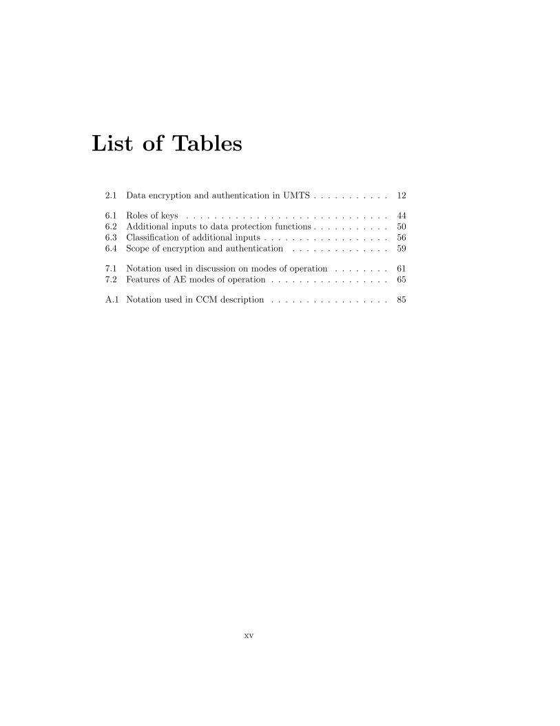
Figure 2.2: User plane protocols in the PS domain
PS domain has evolved from the General Packet Radio Service (GPRS),which is an extension to the GSM network. SGSNs are the equivalent ofMSC/VLRs in the PS domain, since they connect to RNSs of a certaingeographical location.
Gateway GPRS Support Node (GGSN) acts as a gateway to a packetdata network, which typically is the Internet [3GPP04c].
Border Gateway (BG) acts as a gateway to the inter-PLMN GPRS back-bone. If a user is roaming in another PLMN, his packet traffic is tunneledfrom the local SGSN to the GGSN of his home network through the back-bone. [3GPP04c]
2.1.2 Protocols
Figure 2.2 shows the usual user plane protocols of the PS domain. The UTRANphysical layer between the UE and BS is based on Wideband Code DivisionMultiple Access (WCDMA) radio technology [HT04]. The link layer is di-vided into sublayers, namely Medium Access Control (MAC), Radio Link Con-trol (RLC), and Packet Data Convergence Protocol (PDCP). Although notshown in Figure 2.2, there is still one sublayer, named Broadcast/MulticastControl (BMC), which is used when transmitting the same content to severalUEs [3GPP04g]. [3GPP03a]
The MAC layer maps logical channels to transport channels, which are inturn mapped to physical channels by the physical layer [3GPP04d, 3GPP04e].Different logical channels carry different types of data, and several such channelsmay be mapped onto the same transport channel. The MAC layer takes careof multiplexing and priority handling of those different flows. MAC layer alsohandles UE identification on channels common to all UEs. [3GPP04f]
The RLC layer handles segmentation of frames to smaller units suitable fortransmission. RLC operates in three different modes:
Transparent mode Service Data Units (SDUs) are transmitted as they are.No headers are prepended to the frames. Only segmentation and reassem-bly take place.
Unacknowledged mode Detection of missing Protocol Data Units (PDUs)due to transmission errors.

2.2. MUTUAL AUTHENTICATION AND KEY EXCHANGE 9
WCDMA PHY
MAC
RLC
RRC
GMM/SM
WCDMA PHY
MAC
PHY PHY
RLC
RRC
ATM
AAL5
SignalingBearer
SCCP
RANAP
ATM
AAL5
SignalingBearer
SCCP
RANAP
UE BS RNC SGSN
GMM/SM
Figure 2.3: Control plane protocols in the PS domain
Acknowledged mode Automatic retransmission of missing PDUs and detec-tion of duplicate PDUs.
When operating in unacknowledged or acknowledged mode, ciphering is appliedat the RLC level. In transparent mode, ciphering takes place at the MAClevel [3GPP04f]. [3GPP03b]
The primary purpose of PDCP is to compress the headers of the upper layerprotocols, such as IP, Transmission Control Protocol [Pos81b], User DatagramProtocol (UDP) [Pos80], and Real-time Transport Protocol [SCFJ03], whichare likely to be used in the PS domain, thus saving valuable radio link band-width. [3GPP03c]
Figure 2.3 presents the control plane protocols of the PS domain [3GPP03a].The Radio Resource Control (RRC) protocol is used to carry control informa-tion over the radio link. The RRC protocol routes mobility and connectionmanagement control messages submitted by higher layers, and establishes con-trol connections and user plane radio bearers,3 among other things. [3GPP04h]
2.2 Mutual Authentication and Key Exchange
It is obvious that the network has to verify the identity of the users beforeallowing them to initiate or receive calls, or to use any other services. Otherwiseit would be possible to make calls and put the cost on someone else’s account,or to intercept calls or short messages intended to others, for instance.
On the other hand, similarly as the network needs protection against ma-licious users, also the user needs protection against certain attacks. An activeattacker operating a fake RNS might try to set up the same security contextseveral times by a replay attack. Or it might try to collect large amounts ofauthentication challenge–response pairs from the USIM, in order to solve thesecret identification key.4 UMTS uses mutual authentication to provide protec-tion against attacks of this kind [3GPP03e].
3Term bearer refers to information transmission paths that can be created and deleted,except for the signaling bearers used by RRC itself. In contrast, channels are prede-fined entities that exist at physical and MAC layers. They cannot be created nor de-stroyed. [3GPP04a, 3GPP03a]
4This kind of attack is possible in the GSM system but would probably not be very feasible,however. Assuming the most common authentication algorithm COMP128, it would take

10 CHAPTER 2. SECURITY IN UMTS
The key components in mutual authentication are the UE, the currentlyserving MSC/VLR or SGSN, and the HLR/AuC of the user’s home network.MSC/VLR and SGSN play the same role in the authentication procedure, de-pending on the domain for which the authentication is carried out. User au-thentication as well as mobility management are performed independently forboth domains [3GPP04b].
In UMTS, terminal authentication and session key exchange are combinedinto a single procedure, which is called the Authentication and Key Agreement(AKA) procedure. The procedure is based on the fact that a secret user iden-tification value (K) is stored in both AuC and the user’s USIM. MSC/VLRor SGSN wishing to initiate authentication retrieves a set of authenticationvectors from the HLR/AuC using the Mobile Application Part (MAP) proto-col [3GPP04i]. One such vector is used immediately and the rest are stored forfuture authentications. Unused authentication vectors can be further passed toanother VLR when the location of the UE changes [3GPP04b]. Authenticationvectors consist of the following parts:
Challenge which is sent to the UE.
Authentication Token (AUTN) which is also sent to the UE. AUTN con-tains a message authentication code that UE uses to verify that the chal-lenge was really generated in the correct AuC. AUTN also contains asequence number to protect the UE against replay attacks.
Response which is the correct answer to the challenge (also depending on K).
Confidentiality Key (CK) that is used to encrypt transmissions.
Integrity Key (IK) that is used to authenticate control messages.
Authenticating MSC or SGSN sends the challenge and AUTN to the UE, whichin turn verifies the AUTN, calculates the response from the K stored in theUSIM and the challenge, and sends the response back. The UE’s response isverified after that by the network. [3GPP03e]
In addition to calculating the response, different one-way functions are usedto derive CK and IK from the challenge and the secret key. Of course, thishappens both in USIM and in AuC so that CK and IK are never transmittedover the radio link. After a successful AKA exchange, CK and IK are knownto the UE and the MSC/VLR or SGSN. The MSC or SGSN communicates thekeys to the RNC by using MAP, and they are used as session keys to protectsubsequent signaling and the sessions established after the authentication. Asauthentication is performed independently for both domains, there are differentsession keys for both domains too. [3GPP03e]
Further information about mutual authentication and key agreement can befound in [NN03], for example.
2.3 Encryption
As mentioned in Section 2.1.2, encryption can be done at either MAC or RLClayer, which means that encryption is limited to happen only between the UE
several hours even using a smartcard reader [WGB98], not to mention an over-the-air attack.

2.3. ENCRYPTION 11
and the RNC. Encryption is only applied to RLC SDUs. This is true also whenencryption layer is MAC because then RLC operates in transparent mode andno RLC headers are prepended. In acknowledged mode, RLC entities exchangesome flow control messages but they are not encrypted. [3GPP03b]
Figure 2.4 shows how encryption is applied. The encryption algorithm is aproprietary stream cipher called f8, which is a special mode of operation builtaround the KASUMI block cipher [3GPP02b]. In addition to CK, it takes afew more inputs. The length parameter specifies how long the keystream shallbe, the maximum allowed length for the keystream being 20,000 bits.5 Thedirection and bearer identity are taken into account to avoid reusing the samekeystream for both directions or on different radio bearers. The counter in turnensures that the same keystream is never used twice on the same bearer for asingle direction.6 [3GPP03e, 3GPP02a]
The counter parameter is maintained per bearer basis and it consists of twoparts: a short sequence number and a longer Hyperframe Number (HFN). Whenciphering takes place at the RLC layer, the sequence number is equal to theRLC frame sequence number used to detect transmission errors. The number istransmitted in cleartext in the headers of RLC PDUs. In acknowledged mode,its length is 12 bits, whereas in unacknowledged mode it is 7 bits. In transparentmode, the 8-bit Connection Frame Number (CFN) maintained by the MAC layeris used as the sequence number.7 Since the total length of the counter is always32 bits, the length of HFN varies accordingly. [3GPP03b, 3GPP03e]
HFN is incremented every time the shorter counter wraps around. Whenevera new bearer is created, the 20 most significant bits (MSBs) of its HFN areinitialized to a value (START) stored in the USIM. When switching the RNC,it is therefore possible to omit authentication if it has previously been done8 butstill avoid reusing keystreams, even if bearer identifiers (IDs) are reused. Thevalue of START is always updated before it is used according to the maximumHFN of all bearers. When a new AKA exchange takes place, START is set tozero because the keys are changed. [3GPP03e]
Although the network usually initiates the AKA procedure, the lifetime ofsession keys is not solely determined by the network. USIMs contain a parameternamed THRESHOLD that is the maximum allowed value for START parameter.If it is exceeded, new AKA must be initiated. [3GPP03e]
5In a known plaintext attack on a stream cipher, the attacker easily acquires knowledge ofthe corresponding keystream bits. The length of the keystream is sometimes limited to preventthe attacker from gaining too many consecutive keystream bits, in which case he might beable to deduce the subsequent bits or even the encryption key. However, this limitation is notdue to the properties of the f8 encryption algorithm. It is just a requirement arising from thefact that the maximum length of physical layer frames is 20,000 bits [3GPP04j].
6Reusing the keystream reveals partial information about the plaintext to an eavesdropper.See [NN03, Sect. 2.1.3.1] for an illustrative example.
7In principle, CFN is incremented after each frame. However, if several frames are transmit-ted during the same physical layer timeslot, CFN of the first frame is used and the keystreamgenerator is not reinitialized at the frame boundaries. [3GPP04f]
8AKA can be omitted because the session keys can be communicated within a VLR orSGSN area using the MAP protocol. Each pair of CK and IK is associated a value namedKey Set Identifier (KSI). On handover, the UE sends the KSI of the keys currently stored inthe USIM to the new RNC, in order to avoid possible inconsistencies between the currentlyactive keys on both sides.

12 CHAPTER 2. SECURITY IN UMTS
Unprotected frame(s)
MAC and RLCheaders
Data
Protected frame(s)
f8
Direction(uplink/downlink)
CK128 bits
Counter128 bits
Keystream
Length
Bearer ID5 bits
Figure 2.4: Link layer encryption in UMTS
Data class Encryption Authentication
User data Yes NoRLC control data No NoRRC Yes Yes
Table 2.1: Data encryption and authentication in UMTS
2.4 Control Message Authentication
UMTS employs message authentication and integrity checking at the RRClayer [3GPP04h]. Therefore, authentication is not applied to user data norRLC flow control messages, since RRC runs above RLC. As this is the case,RRC messages can also be encrypted, in addition to authentication. Table 2.1summarizes how encryption and authentication are applied to different classesof data.
Authentication uses a special function named f9, which is another mode ofoperation around the KASUMI algorithm [3GPP02a]. Inputs to f9 include, inaddition to IK and the message to be authenticated, a message sequence numberand a transmission direction bit, just like in encryption, though their purposeis different. In encryption, the purpose of these inputs is to prevent keystreamreuse, but in authentication, they are used to prevent message replay. Thesequence number is comprised of HFN and a shorter sequence number includedin each RRC frame. HFN initialization depends on the same START value asin encryption. [3GPP03e]
Moreover, f9 requires yet another input parameter, namely a random valuegenerated by the RNC. This parameter is called FRESH, and it is transmittedin the beginning of the RRC connection and used throughout that connection.

2.5. COMPARISON WITH GSM 13
It prevents control message replays by the UE (or an attacker pretending tobe one). In other words, the FRESH parameter protects the network frommalicious terminals, whereas the sequence number protects users from falsenetworks, since the START value is determined by the USIM. [3GPP03e]
In contrast to f8, there is no radio bearer identity input to f9, due to ahistorical reason [NN03, Sect. 2.1.4]. As there are several signaling bearers, thismay seem to facilitate replaying RRC messages on different signaling bearers.However, this problem has been fixed by attaching the bearer identity to themessage to be authenticated [3GPP04h].
Not all RRC messages are integrity protected [3GPP04h], for obvious rea-sons. For example, it is not possible to apply protection before FRESH andSTART have been transmitted and IK has been derived.
If a message is to be protected, f9 outputs a 32-bit Message AuthenticationCode (MAC-I9) [3GPP02a]. This value is inserted to the message. When themessage is received, the receiver recomputes the value from the message con-tents and checks whether it matches the MAC-I. Figure 2.5 shows how integrityprotection works in RRC. [3GPP04h]
2.5 Comparison with GSM
The GSM security architecture naturally has many features similar to those ofthe UMTS network. The main differences are:
• GSM does not support network authentication nor prevent key replay.This leaves room for an active attack that is described in Section 2.5.2.
• GSM control messages are not integrity protected, which is a major se-curity problem. See [WW02, Sect. 15.9.5] for examples how this short-coming can be exploited. All error checking and correction codes arelinear [ETSI00d], so encrypting them with an additive stream cipher doesnot contribute much to authenticity.
• In GSM, encryption is applied at the lowest possible level, even lower thanchannel coding [ETSI00b].10 Therefore, in a known plaintext attack, theattacker gains knowledge of even more consecutive keystream bits than heknows those of the plaintext. Even ciphertext only key recovery attacksare possible.
2.5.1 Encryption in GSM
Figure 2.6 shows how encryption works in GSM. There is a ciphering key (Kc)derived from the identification key (Ki) and the authentication challenge, justlike in UMTS. Kc together with a physical layer frame sequence number deter-mines the keystream, which is split into two parts, one used for the downlinkand the other for the uplink stream. The sequence number is bound to the clock
9The message authentication code is denoted by MAC-I to avoid ambiguities with theMAC layer, and also to distinguish it from another authentication values called MAC-A andMAC-S.
10In fact, there are two information bits per burst that are not encrypted. These bits arecalled stealing flags and they indicate whether control data are passed instead of user dataalong the data stream. [ETSI00d]

14 CHAPTER 2. SECURITY IN UMTS
Unprotected message
Protected message
f9Direction(uplink/downlink)
IK128 bits
Counter128 bits
FRESH32 bits
MAC-I32 bits
Bearer ID5 bits
Figure 2.5: Integrity protection in RRC

2.5. COMPARISON WITH GSM 15
Unprotected frame
Frame tailsTraining sequence
Stealing flags
Data
Protected frame
A5
Selectbits
228-bit keystream
114-bitkeystream
Direction(uplink/downlink)
Kc64 bits
Frame #22 bits
Figure 2.6: GSM ciphering
of the base station and thus known to the Mobile Station (MS) due to synchro-nization. The sequence number wraps around every 3.5 hours. [ETSI99b]
Originally, the encryption algorithms used to protect over-the-air GSM traf-fic, called A5/1 and A5/2, were kept secret as an additional security mea-sure [MP92, Sect. 4.3.3]. However, they were completely reverse engineeredin 1999 [BGW99]. Several attacks on them have been published. The weakerversion, A5/2, is already completely broken, as the session key can be recoveredfrom a few dozen milliseconds of ciphered conversation [BBK03]. Pretty efficienttime–memory tradeoffs exist against A5/1, which allow key recovery in a fewseconds or minutes, depending on the amount of available ciphertext. Theseattacks require a huge amount of preprocessing and disk storage. See [BSW01]for details.
A5/2 was introduced later than A5/1 because certain organizations opposedusing strong cryptography in confidentiality protection. However, as data in-tegrity in GSM depends solely on encryption, integrity protection of data wasweakened too. Nowadays, when online A5/2 key recovery is possible, an activeMan-in-the-Middle (MitM) impersonator can hijack telephone calls. The at-tacker listens to the victim call, and once he has collected an adequate amountof ciphertext and recovered the key, he closes the session with the victim userand takes over the call.

16 CHAPTER 2. SECURITY IN UMTS
2.5.2 Key Replay Attack
Elad Barkan, Eli Biham, and Nathan Keller presented an interesting activeattack on the GSM network. The attack leverages the lack of network authen-tication and key replay prevention mechanism, and was originally presentedin [BBK03, Sect. 7.1].
The idea is that an attacker records an A5/1-encrypted session, includingthe authentication challenge, which together with the (unknown) Ki uniquelydetermines the encryption key. Later, the attacker impersonates the network tothe user and sends the recorded challenge to the user, which causes the sameencryption key to be used within this session. As the network is free to chooseany encryption algorithm the client supports [ETSI99b], the attacker choosesA5/2,11 obtains an adequate amount of ciphertext, and recovers the key. Afterthat, he can use the key to decrypt the previously recorded conversation.
11This is always possible because it is mandatory to implement A5/2 [ETSI99a]. However,removal of this requirement has been proposed due to this attack [Bro04].

Chapter 3
WLAN Security
IEEE 802.11 is the standard defining how WLANs should operate. It containsdefinitions for both physical layer and link layer, the latter of which is also calledthe MAC layer. The original version of the standard [IEEE97] indeed addressedsecurity issues, but there were serious flaws in the security specification, how-ever. For example, using linear checksums encrypted with an additive streamcipher1 does not provide very good integrity protection. Moreover, stream ci-pher initialization vectors (IVs) could have been made longer than 24 bits.The vulnerabilities of this original security protocol, Wired Equivalent Privacy(WEP), and potential ways to exploit them are discussed in [BGW01].
The IEEE has recently updated the security specification to strengthen thesecurity of WLANs [IEEE04]. The updated standard defines how WLAN sta-tions can establish Robust Security Network Associations2 (RSNAs) betweeneach other. An RSNA between stations allows them to authenticate each otherusing various methods, establish fresh cryptographic keys, and use effectivealgorithms for data protection. This chapter describes this improved securityscheme because it is more relevant if we want to examine mechanisms that couldbe reused in future communications systems.
There are two operational modes for WLANs:
Ad hoc mode where the stations communicate directly with each other, and
Infrastructured mode where there is a fixed Access Point (AP) that medi-tates all the traffic between other stations and possibly provides furtherconnectivity to other networks and APs. Using this mode indeed requiresthat some infrastructure is installed to the area where the stations areoperated.
The operational mode used affects the security mechanisms. In ad hoc mode,RSNAs are established with each other station to be communicated with. Incontrast, if an AP is present, an RSNA is typically formed only with it.
An overview of station authentication methods is given in Section 3.1. Afterthat, data protection protocols are presented and discussed. The description ofthe WLAN architecture presented here is based on [IEEE99] and [IEEE04].
1The cipher was RC4, a proprietary stream cipher by RSA Security, Inc. However, thedetails of the algorithm had already been leaked to the public [Sch96, Chpt. 17].
2The security associations of this new type are called robust because those of WEP wereapparently not.
17

18 CHAPTER 3. WLAN SECURITY
3.1 Station Authentication
WLAN station authentication is based on the generic port-based access controlmodel defined for Local Area Networks (LANs) [IEEE01]. RSNA establishmentbetween two stations may begin with an Extensible Authentication Protocol(EAP) [ABV+04] exchange. EAP is a generic framework for performing au-thentications, possibly using a distinct authentication server. The authentica-tion methods used with EAP produce a shared secret between the parties, whichis called the Pairwise Master Key (PMK). The PMK is a long-term link key thatis used to generate session keys for data encryption and authentication.
The EAP specification defines authentication protocols for one-time pass-words and token cards. A mechanism for MD5-based [Riv92] authenticationanalogous to the Challenge Handshake Authentication Protocol [Sim96] is de-fined too. Additional protocols are currently being specified. One such protocolis EAP-AKA, which allows authentication using USIMs and the UMTS AKAprotocol [AH04]. EAP-SIM is a similar protocol for GSM Subscriber IdentityModules (SIMs) [HS04].
Nevertheless, it is not mandatory to use EAP. It is also possible to use a pre-shared key (PSK) directly as the PMK. This is possible because the possession ofthe correct PMK is verified during subsequent steps of the RSNA establishmentprocedure.
Each PMK has an identifier, which is derived from the station addresses andthe key itself using HMAC-SHA1-128 [KBC97, NIST95]. This 128-bit PMKIdentifier (PMKID) is unique with an overwhelming probability, given any rea-sonable number of PMKs. It is useful when a station has been absent from thenetwork and wants to join it again. If both parties have cached the key, it is notnecessary to run the authentication procedure again. The associating3 stationjust has to send the PMKID. The identifiers are also useful when the link keycan be communicated between several APs because then authentication can beomitted when stations switch between those APs.
3.2 The 4-Way Handshake
A procedure called 4-way handshake completes RSNA establishment. In ac-cordance with the name, four messages are exchanged between the stations, asshown in Figure 3.1. The supplicant is the station that authenticates itself tothe authenticator. If an AP is involved, it sends the first handshake messagebecause APs always act as authenticators when establishing RSNAs.
The main function of the 4-way handshake is to generate short-term sessionkeys to be used with data protection algorithms. Both parties generate randomnumbers4 and exchange them. These values alongside with the parties’ MACaddresses5 and the PMK are used as inputs to a key derivation algorithm pro-
3In WLAN terminology, association just means establishing a connection with anotherstation. In infrastructured mode, normal stations initiate associations only with the AP.
4These random numbers are called nonces by the specification, as shown in Figure 3.1.However, in this thesis, we follow the terminology of [WHF03], where nonce refers to anyvalue, random or not, that is not repeated in the same context.
5MAC address is a unique 48-bit number identifying the device. Each frame must containthe MAC addresses of the sender and the receiver, since the frames are transmitted on ashared physical channel.

3.2. THE 4-WAY HANDSHAKE 19
AuthenticatorSupplicant
ANonce
SNonce, MIC
MIC, Encrypted GTK
MIC
Figure 3.1: The 4-way handshake
ducing a Pairwise Transient Key (PTK) as a result. The supplicant computesthe PTK after the first step and the authenticator after the second step. Thekey derivation algorithm is based on HMAC-SHA-1 where the PMK is used asthe key.
The PTK is divided into three parts:
Key Confirmation Key (KCK) that is used to compute and verify the Mes-sage Integrity Codes6 (MICs) in the handshake messages. The authenti-cation algorithm is either HMAC-MD5 or HMAC-SHA1-128.
Key Encryption Key (KEK) that is used to encrypt the Group TemporalKey (GTK) included in the third message. The encryption algorithm iseither RC4 or AES.
Temporal Key (TK) that is used with the encryption and data authentica-tion algorithm to protect unicast traffic.
The MICs are calculated over the handshake messages using KCK. Theyverify that the parties share a common PMK and make it possible to use PSKauthentication, in addition to preventing active attacks on the 4-way handshake.
TK is used to protect unicast traffic between the stations, but there is adifferent key for multicast and broadcast traffic, namely GTK. This key is es-sentially a random number chosen by the authenticator and is used to protectnon-unicast traffic originating from it. TK can be renewed by re-executing the
6The WLAN specification uses rather term Message Integrity Code than Message Authen-tication Code to avoid ambiguities with acronyms.

20 CHAPTER 3. WLAN SECURITY
4-way handshake, but GTK can be changed by a lighter group key handshakeusing the old KCK and KEK.
It is good to note that in infrastructured mode, only the AP needs to havea GTK, since the other stations never have to broadcast anything as they arecommunicating with the others via the AP. However, in ad hoc mode, the 4-way handshake must be performed twice, so that both parties send their ownGTK, if the both parties wish to send non-unicast messages. In principle, itis possible to execute the 4-way handshake once and then use the group keyhandshake for the other direction. However, this is not mandated to allow forsimple implementations.
3.3 Data Encryption and Authentication
In WLANs, both encryption and integrity protection are applied to user data.The invariable MAC headers of data frames are also integrity protected, but allcontrol messages are left unprotected. In contrast, some UMTS control messagesare even more protected than user data, as said in Section 2.4. Possible reasonsfor this are investigated in Section 6.5.
The enhanced WLAN standard defines two modes for data protection:
• Counter-Mode/CBC-MAC Protocol (CCMP)
• Temporal Key Integrity Protocol (TKIP)
The standard allows using also vendor-specific algorithms. Stations advertisethe cipher suites they support, and the station willing to associate chooses oneof them and indicates its choice in the association request. This happens beforethe 4-way handshake and possible EAP exchange.
Although TKIP is defined by the standard, it is not required to implementit. TKIP is a workaround that tries to fix the most serious shortcomings ofWEP by turning the IV to a 48-bit counter and adding a non-linear integritychecking code. It is designed so that it would be possible to upgrade legacydevices to use it. However, this implies that the integrity checking code cannotbe very strong. Otherwise the legacy devices might not be able to compute itonline.
CCMP is more interesting because it is mandatory to implement in devicesclaiming RSNA compliance and is currently believed to provide good security.CCMP uses AES in Counter with CBC-MAC (CCM) mode [WHF03], thus pro-viding both encryption and data authentication. Figure 3.2 shows how CCMPworks. The CCM mode itself is discussed in more detail in Chapter 7 andAppendix A.
The nonce required by the CCM mode is constructed from a 48-bit sequencenumber, a MAC header field, A2, and the frame priority.7 A2 contains theaddress of the transmitter, so it makes the keystream different for both direc-tions even though the same sequence number and priority were used. The se-quence number must be incremented for each packet, thus preventing keystream
7The frame priority is a 4-bit value affecting the CCM nonce construction. However, it isnot transmitted along the frame. The specification says that the priority is always set to zeroand reserved for future use.

3.3. DATA ENCRYPTION AND AUTHENTICATION 21
ConstructAAD
Unprotected frame
Constructnonce
AES-CCM
Sequence #48 bits
Key ID2 bits
TK or GTK
CCMP header
MAC header
Encrypted data and 64-bit MIC
AAD Nonce104 bits
Datamax. 2296octets
Protected frame
A2, Priority
Figure 3.2: CCMP operation

22 CHAPTER 3. WLAN SECURITY
reuse and enabling detection of replayed frames. With 48 bits counter wrap-around does not happen very frequently. Nevertheless, the specification man-dates changing the session key if wrap-around happens because it states thatno sequence number should be used more than once.
The sequence numbers are maintained separately for each TK and GTK.As TK associations are bidirectional, there must be different sequence numberregisters for transmission and reception. Transmission counters are incrementedwhen frames are sent, the values being transmitted along them, whereas recep-tion counters are used to detect frame replay. Interestingly, the specificationsays that stations must maintain separate reception counters for each priority.The reason is that then it is possible to reorder frames according to their pri-orities en route,8 without confusing the replay prevention system. The priorityclasses can be thought to form separate logical channels that are multiplexed toa single transport channel.
8Unlike many other radio communications systems, in infrastructured mode of WLAN itis possible to reorder frames en route, since they are routed via the AP.
Chapter 4
Bluetooth Security
Note: Parts of this chapter will be separately published in [RN04].
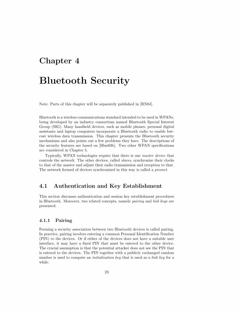
Bluetooth is a wireless communications standard intended to be used in WPANs,being developed by an industry consortium named Bluetooth Special InterestGroup (SIG). Many handheld devices, such as mobile phones, personal digitalassistants and laptop computers incorporate a Bluetooth radio to enable low-cost wireless data transmission. This chapter presents the Bluetooth securitymechanisms and also points out a few problems they have. The descriptions ofthe security features are based on [Blue03b]. Two other WPAN specificationsare considered in Chapter 5.
Typically, WPAN technologies require that there is one master device thatcontrols the network. The other devices, called slaves, synchronize their clocksto that of the master and adjust their radio transmission and reception to that.The network formed of devices synchronized in this way is called a piconet.
4.1 Authentication and Key Establishment
This section discusses authentication and session key establishment proceduresin Bluetooth. Moreover, two related concepts, namely pairing and link keys arepresented.
4.1.1 Pairing
Forming a security association between two Bluetooth devices is called pairing.In practice, pairing involves entering a common Personal Identification Number(PIN) to the devices. Or if either of the devices does not have a suitable userinterface, it may have a fixed PIN that must be entered to the other device.The crucial assumption is that the potential attacker does not see the PIN thatis entered to the devices. The PIN together with a publicly exchanged randomnumber is used to compute an initialization key that is used as a link key for awhile.
23

24 CHAPTER 4. BLUETOOTH SECURITY
4.1.2 Link Keys
Link key is a shared secret between the communicating devices. In principle,there are four types of link keys:
• combination keys
• unit keys
• temporary keys1
• initialization keys
Unit keys are used by devices with limited memory resources. In practice,it means that the device with limited resources uses the same link key with allother devices. This implies that using them is very insecure, since it facilitatesmutual eavesdropping among different communicating peers. In fact, their useis deprecated and they are ignored in this discussion.
Temporary keys are used in point-to-multipoint configurations. As the namesuggests, such configurations are usually relatively short-lived. Applicationsmay make the slaves use a common encryption key derived from this commontemporary link key to allow encryption of broadcast traffic. Note that alsounicast traffic is encrypted with the common key when a temporary link keyhas been set up, as will be explained in Section 4.2.1. After the master hasfinished broadcasting that needs encryption, the slaves can be told to fall backto the previous link keys.
In most cases, the link key is a combination key, denoted by KAB in thespecification. The key is derived from the addresses of the devices and randomnumbers generated by both of them, hence the name combination key. Accord-ing to the specification, combination keys are semi-permanent, in the sense thatthey can be changed but typically have long lifetimes. In fact, the specificationsuggests that combination keys can be stored into non-volatile memory andused to authenticate and generate encryption keys for future sessions. So it isreasonable to assume that link keys do not change very often in point-to-pointconfigurations.
In addition to these four types of link keys, there is an interface for importinglink keys. Therefore, it is possible to use higher layer key exchange protocols, forinstance. These imported keys have the same function as unit and combinationkeys although not specifically listed in [Blue03b, Part H, Sect. 3.1].
Whenever the link key is changed, the related message exchange is protectedby the previous link key. Initialization keys are the first link keys and used onlyfor this purpose just after pairing, and they are discarded after a new linkkey has been generated. One could argue that changing the link key does notprovide any additional security, since if he sees all the messages and knows theprevious link key,2 an attacker can easily derive the new key. This is true, butif he misses even a single message related to changing the link key, the attacker
1In [Blue03b], keys of this type are called master keys and denoted by Kmaster , but thisterm is a bit misleading. In specifications of some other wireless communications systems,such as those of WLANs [IEEE04], long-term link keys (combination key equivalents) arecalled master keys.
2This assumption is realistic and can be accomplished by an exhaustive PIN search, forexample. This was pointed out in [JW01, Sect. 4]. Although the paper discusses Bluetoothversion 1.0B, the attack can be applied also to the newest version with a small modification.

4.1. AUTHENTICATION AND KEY ESTABLISHMENT 25
is unable to derive the new link key or any subsequent link keys generated infuture. Although not explicitly stated in the specification, it seems that this isthe rationale of the link key changing procedure, to provide security in practice,if not in theory.
A change of the link key is followed by two other procedures, which are
1. Mutual authentication
2. Encryption key exchange (if encryption is used)
Authentication and key exchange are allowed to happen at any other time too,but they are mandatory after link key renewal. Section 4.1.3 explains howauthentication works in Bluetooth and Section 4.1.4 shows how encryption keysare agreed on.
4.1.3 Authentication
Bluetooth uses a special one-way algorithm named E1 when authenticating otherdevices. It is based on the SAFER+ block cipher [MKK98]. The inputs to E1
are:
• current link key
• device address of the claimant3
• 128-bit challenge
The challenge is generated by the verifier and sent to the claimant. Bothparties run E1 and the claimant sends the response to the verifier that checkswhether the results match. E1 produces also another result, which is calledAuthenticated Ciphering Offset (ACO). This 96-bit value is used in key exchangeand is discussed in Section 4.1.4.
Authentication always takes place for both directions after the link key hasbeen changed. Then the order is fixed: first the master authenticates the slaveand then vice versa. This is also true when a temporary multipoint key is takeninto use. It is up to the application whether authentication is performed atother times. These additional authentications do not necessarily have to bemutual. In principle, authentication can be performed arbitrarily many timesand in arbitrary order unless the application imposes some restrictions on that.
4.1.4 Encryption Key Exchange
Encryption keys are generated by an algorithm called E3, which produces a128-bit result. The inputs to E3 are:
• current link key
3The address of the claimant is included to prevent a reflection attack, where the claimantcounter-challenges the verifier with the same challenge, waits for the response, and then an-swers the original challenge. However, the specifications state that this should not be aproblem anyway, since all service request are dealt in the order they were received. Neverthe-less, including the claimant address prevents such attacks on not-so-specifications-compliantimplementations too. Section 6.2 gives another reason why inclusion of the claimant addressis vital for security.
26 CHAPTER 4. BLUETOOTH SECURITY
• 128-bit random number
• Ciphering Offset number (COF)
The random number is generated by the master and is supplied to the slavewith the control message that requests starting encryption. The last input,COF, takes one of the following values:
• the device address of the master repeated twice, if the link key is a tem-porary key, or
• ACO produced by the latest authentication, otherwise.
4.2 Encryption
Bluetooth uses an encryption algorithm to conceal the transmitted data fromeavesdroppers. The encryption algorithm is a stream cipher called E0, whichis based on Linear Feedback Shift Registers (LFSRs) and a summation com-biner [Rue85]. The length of the encryption key can be varied between 8 and 128bits. The length is negotiated using the Link Manager Protocol (LMP) [Blue03b,Part C].
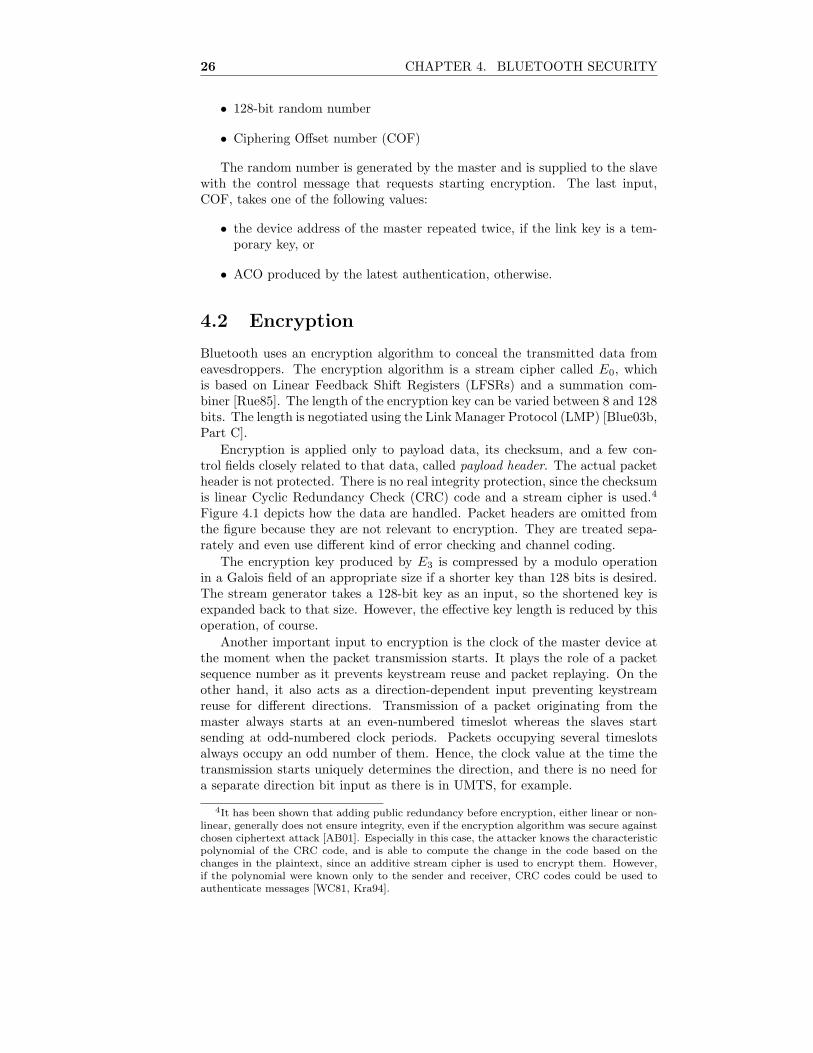
Encryption is applied only to payload data, its checksum, and a few con-trol fields closely related to that data, called payload header. The actual packetheader is not protected. There is no real integrity protection, since the checksumis linear Cyclic Redundancy Check (CRC) code and a stream cipher is used.4
Figure 4.1 depicts how the data are handled. Packet headers are omitted fromthe figure because they are not relevant to encryption. They are treated sepa-rately and even use different kind of error checking and channel coding.
The encryption key produced by E3 is compressed by a modulo operationin a Galois field of an appropriate size if a shorter key than 128 bits is desired.The stream generator takes a 128-bit key as an input, so the shortened key isexpanded back to that size. However, the effective key length is reduced by thisoperation, of course.
Another important input to encryption is the clock of the master device atthe moment when the packet transmission starts. It plays the role of a packetsequence number as it prevents keystream reuse and packet replaying. On theother hand, it also acts as a direction-dependent input preventing keystreamreuse for different directions. Transmission of a packet originating from themaster always starts at an even-numbered timeslot whereas the slaves startsending at odd-numbered clock periods. Packets occupying several timeslotsalways occupy an odd number of them. Hence, the clock value at the time thetransmission starts uniquely determines the direction, and there is no need fora separate direction bit input as there is in UMTS, for example.
4It has been shown that adding public redundancy before encryption, either linear or non-linear, generally does not ensure integrity, even if the encryption algorithm was secure againstchosen ciphertext attack [AB01]. Especially in this case, the attacker knows the characteristicpolynomial of the CRC code, and is able to compute the change in the code based on thechanges in the plaintext, since an additive stream cipher is used to encrypt them. However,if the polynomial were known only to the sender and receiver, CRC codes could be used toauthenticate messages [WC81, Kra94].

4.2. ENCRYPTION 27
Payload header and data
CRC
Protected payload
16-bitchecksum
Master’s clock(excluding LSBand MSB)26 bits
Key128 bits
Master’s address48 bits
Compression
Expansion
Key length
8-128 bits
128 bits
Keystreammax. 2744 bits
PSfrag replacements
E0
Figure 4.1: Bluetooth packet payload encryption
In Bluetooth, change of the encryption key after clock wrap-around is notmandated. One timeslot takes 625 microseconds of time, so the wrap-aroundperiod (226 timeslots) is about 11 hours and 39 minutes.
4.2.1 Encryption Modes
Bluetooth defines three encryption modes:
1. No encryption
2. Point-to-point only encryption
3. Point-to-point and broadcast encryption
Note that it is not allowed to have both mode 2 and mode 3 devices si-multaneously in a piconet, since broadcast messages must be either encryptedor unencrypted. In fact, switching between these two modes simply meansswitching between temporary master keys and combination keys, and derivingappropriate encryption keys. Also unicast traffic is encrypted using the commonkey in mode 3. Consequently, any device can decrypt all messages sent withinthe piconet, even if intended only to some other device. In contrast, mode 2allows for having distinct keys, thus preventing eavesdropping by other piconetmembers.

28 CHAPTER 4. BLUETOOTH SECURITY
4.2.2 Status of Encryption Algorithm E0
In 1999, Miia Hermelin and Kaisa Nyberg showed how it is possible to recoverthe initial state of the LFSRs from 264 consecutive keystream bits doing a workof 264 [HN99]. The amount of work has later been reduced to 261 and therequired knowledge of keystream bits to 250 [EJ00]. These attacks exploit linearcorrelations in the summation combiner. Nevertheless, these attacks are oftheoretical nature since the LFSRs are reinitialized after each packet and thelength of the keystream never exceeds 2744 bits.5
At the moment, algebraic attacks seem to be the most effective attackson E0. Matthias Krause devised an attack requiring a work of 277 but only128 consecutive bits of known plaintext [Kra02, Sect. 7]. That amount is emi-nently realistic for an attacker to obtain but the workload is still prohibitive andequivalent to exhaustive key search of a 78-bit key. Later, Frederick Armknechtand Krause showed how to recover the initial state from 223 keystream bitsdoing a work of 268 [AK03]. By using a technique called fast algebraic attack,which requires some precomputation, the amount of work can be reduced to255 [Cou03, Arm04b].
The aforementioned attacks concentrate on discovering the initial state ofthe LFSRs from the keystream bits. Moreover, it has recently been proventhat having an effective algorithm for initial state recovery yields an effectivealgorithm for recovering the secret key [ALP04].
According to Armknecht, recovering E0 keys using present known plaintextattacks would require about 128 GB of memory and 8 MB of keystream. Withpresent computing machinery, it would take at least 159 years to perform thecomputations. [Arm04a]
4.2.3 Upgrade of Encryption Algorithm
Even if not breakable in practice, E0 is of lower security level than AES-basedstream ciphers are currently believed to be. Therefore, there are incentives tointroduce a stronger encryption mechanism to Bluetooth, preferably based onthe AES.
Nevertheless, support for E0 cannot be removed, in order to provide compat-ibility with legacy devices. Previous attacks on the GSM system by Barkan et
al. show that two different encryption algorithms within the same system mayinterfere in an undesirable manner. Section 4.3 shows how the attack discussedin Section 2.5.2 could be used on the Bluetooth system if amended by anotherencryption algorithm.
4.3 Key Replay Attack
In the infamous attack on the GSM system by Barkan et al., the attacker canforce the victim to reuse a previously used encryption key with the weak algo-rithm, and then recover the key. Then the attacker can decrypt the previously
5The Bluetooth specifications state that the maximum size of payload is 2745 bits. Thismaximum is achieved by type DM5 packets with 228-byte payload, which maps to 2745 bitsdue to error-correcting channel coding. However, encryption is applied before channel codingand therefore the maximal-length keystream is used with type DH5 packets having 343-bytepayload, which equals to 2744 bits.

4.3. KEY REPLAY ATTACK 29
generated ciphertext, even if strong encryption has been used. This sectionshows that such an attack may also be possible in Bluetooth if appropriatecounter-measures are not taken. The fundamental cause of the problem is thatit is possible to replay encryption keys. Section 4.3.4 presents recommendationsfor the counter-measures that would be sufficient to allow a second encryptionalgorithm to be securely taken into use in Bluetooth system.
It should be noted that recovering encryption keys is not the only exploit ofthe possibility for encryption key replay. For instance, Eric Gauthier presenteda key replay attack applicable against the EAP-AKA protocol when a Bluetoothlink is used between the victim devices [Gau04].
Let us now assume that a second alternative encryption algorithm is insertedto the Bluetooth system. Then the support for the original E0 algorithm will bemaintained to ensure backward compatibility. Hence, it is necessary to inserta cipher negotiation mechanism to LMP so that the devices can agree on acommon algorithm. Moreover, it is natural to impose change of encryption keyafter change of encryption algorithm to prevent the same encryption key frombeing used with two different algorithms.
We also make the following additional assumptions about how the new fea-ture is used in Bluetooth system. The assumptions are realistic and in accor-dance with the current specification.
1. The same E3 algorithm is used to generate the encryption keys for all en-cryption algorithms. This is reasonable, since most modern block ciphers,such as AES, use 128-bit keys.
2. The application does not restrict the order of execution of authenticationprocedures.
3. The link key is not changed often (i.e. it remains the same throughout allsessions involved in the attack).
Finally, we make the general assumption that passive wiretapping and record-ing of Bluetooth communication as well as active MitM impersonation is possiblein Bluetooth. In particular, we assume that the attacker can impersonate themaster to a slave, and send control messages to the slave. Note that we donot assume that the master can adjust its clock as is required by Gauthier’sattack [3GPP04k, Sect. 2].
It is shown is this section that if these assumptions hold, then it is possiblefor an active attacker to force a Bluetooth slave device to reuse a previouslyused encryption key with an encryption algorithm selected by the attacker. Inthis manner, a situation is created where the attack of Barkan et al. works. Thisviolates the requirement that the different encryption algorithms must not poseany threat to each other.
At first, in Section 4.3.1 we consider a simple case involving only combination-type link keys. In Section 4.3.2, we show that under certain conditions thisattack can be even easier to perform. Section 4.3.3 discusses whether the attackcan be extended to sessions containing point-to-multipoint transmissions.
4.3.1 Basic Attack
In case of point-to-point configurations, which we are now considering, the valueof ACO is directly used as COF, the input to the encryption key generation al-

30 CHAPTER 4. BLUETOOTH SECURITY
gorithm E3. If authentication is performed for both parties, the ACO producedby the latest authentication is used. Hence the factors that determine the en-cryption key are:
• current link key
• master-supplied random number
• challenge supplied by the verifier of the last authentication
• device address of the claimant of the last authentication
The attack works as follows. At first, the attacker records a session that isencrypted by using a strong algorithm. Prior to that, he sees the master supplythe last authentication challenge, observes the random number attached to theencryption start request, and saves those messages.
Later, at a moment best suitable for him, the attacker becomes active andimpersonates the master to the slave. The old link key is used, so there is no needfor mutual authentication. Now the attacker runs the negotiation procedure totake the weak encryption algorithm into use. As explained earlier, a procedureto exchange a new encryption key is performed. It may be possible to usean existing ACO value, as discussed in the next subsection. If a new ACOvalue is needed, the attacker requests the slave to authenticate itself by sendingthe previously recorded challenge, as allowed by assumption 2. Being unawareof the real link key, the attacker of course cannot verify the response of theslave, but the result is that the challenge he supplies defines the same ACO, asbefore. Then the attacker initiates encryption by replaying the random numberit recorded from the previous session. The resulting encryption key is identicalto the one of the session that the attacker recorded.
It is important to note that if the master is the verifier in the last authenti-cation, the encryption key solely depends on values supplied by him.6 The slavehas then no opportunity to affect the key. This enables the attacker to set upthe same encryption key by replaying these values, since by assumption 1 thesame E3 algorithm is used with both encryption algorithms. Now the attackercan try to recover the key by using an attack on the weak algorithm, and thendecrypt the ciphertext created using the strong algorithm if he succeeds.
4.3.2 Using Existing ACO
A variation of the attack may be possible if the same ACO is allowed to beused for several encryption key computations. If the same ACO were used,COF would remain constant for long periods of time, just like the link key.Then we are again in the situation where the master is the only one who affectsthe encryption key. The specifications do not forbid reusing ACOs. In fact,they encourage using the same ACO for several key computations in certainsituations. When discussing mutual authentication after a temporary key hasbeen distributed, they say [Blue03b, Part H, Sect. 3.2.8]:
6Indeed, the encryption key depends on the current link key the attacker does not know.But because of assumption 3, it is constant throughout the attack and in that sense does notaffect the encryption key. As regards to the device address, the same holds.

4.3. KEY REPLAY ATTACK 31
The ACO values from the authentications shall not replace the cur-rent ACO, as this ACO is needed to (re)compute a ciphering keywhen the master falls back to the previous (non-temporary) linkkey.
Therefore, it is highly probable that several implementations do not require afresh ACO for each encryption key derivation. Attacking on such implemen-tations necessitates only replaying the random number input for E3, not theauthentication challenge, thus rendering assumption 2 unnecessary. It is noteven necessary for the attacker to know the last challenge, it is required onlythat the replay takes place when the ACO value is the same as in the recordedsession.
4.3.3 Point-to-Multipoint Configurations
Let us assume that the application allows the master to make the slaves switch totemporary link and encryption keys, and the attacker has recorded a session thatcontains such encrypted broadcast episodes. It is clear that the attacker is ableto recover such parts of the recorded session that were encrypted using a point-to-point key since he can replay separately all authentications and key exchangeshe has seen. But could the attacker somehow recover broadcast encryption keystoo?
Before broadcast encryption can be started, a new temporary link key iscreated and transmitted to the slaves, in encrypted form of course. But asmutual authentication always occurs after this, there is no way for the attackerto remain undetected since he does not know the new link key. [Blue03b, Part H,Sect. 3.2.8]
However, there can be applications that constantly use the temporary linkkey. In that case, the temporary key is never relinquished and the attack workswell, just like in the point-to-point case. Note that in this case, the attackerneed not know the authentication challenge, but can send any plausible value,since COF is derived from the master’s address.
4.3.4 Possible Counter-Measures
Assumption 3 stated that the link key is not changed often. However, if thespecifications dictated that the link key must be changed regularly, that wouldoffer some protection against this replay attack. Replaying the challenge andthe random number would no longer yield the same encryption key, had the linkkey been changed. Moreover, as mutual authentication must always occur afterchange of link key, changing link keys frequently would certainly offer protectionagainst attacks of this kind. Point-to-multipoint applications constantly switch-ing between combination and temporary group keys naturally use this means ofprotection.
Another possibility to protect against replay attacks is to make the slavealways supply the last challenge. LMP definition rules that the slave sup-plies the last challenge in mutual authentication after the link key has beenchanged [Blue03b, Part C, Sect. 4.2]. However, this does not by itself preventthe master from initiating new authentication and key exchange proceduresimmediately after that.

32 CHAPTER 4. BLUETOOTH SECURITY
We made the assumption that after each negotiation of encryption algorithma new encryption key must be exchanged. We assumed that in this processauthentication is performed only one way: master authenticates the slave. Onemight think that requiring mutual authentication would be sufficient to preventthe attacker from replaying an encryption key. However, this is not the case.By impersonating the slave to the real master, the attacker can forward thechallenge to the master and get the correct response which it forwards to theslave.
We implicitly assumed that the attacker can freely select the encryptionalgorithms in protocol negotiation phase. This assumption is based on the factthat currently there is no other integrity protection mechanism than encryptionin Bluetooth, and encryption cannot be used before the algorithm has beenagreed on. In theory, using message authentication codes based on link keysto protect the negotiation would prevent this attack. However, it would notprevent other types of encryption key replay attacks, such as Gauthier’s attack.
Another counter-measure that prevents the same encryption key from beingused for two different encryption algorithms is to specify a new different E3
algorithm for each new encryption algorithm. But again, other types of replayattacks would not be neutralized.

Chapter 5
Security in IEEE 802.15
WPANs
The newest version of the Bluetooth specification is numbered 1.2. Parts ofthe older Bluetooth specification version 1.1 have been accepted as IEEE Stan-dard 802.15.1 [IEEE02]. After that, the IEEE has approved two other specifica-tions to its 802.15 WPAN standard series. Their security features are discussedin this chapter.
The data transmission rate of Bluetooth radios is 1 Mbps [Blue03a, Part A,Sect. 1.1]. This was considered inadequate for some applications, and there-fore the IEEE devised another standard for high-rate WPANs. This standard(IEEE 802.15.3) is not based on the Bluetooth architecture, and its securityfeatures are presented in Section 5.1. It allows for transmission rates up to55 Mbps [IEEE03a, Sect. 5.4.1]. The Bluetooth SIG is also developing a high-rate version of their specification, though the work seems to be progressingslowly.
Interestingly, there is also a specification for low-rate WPANs by the IEEE.This standard, named IEEE 802.15.4, is intended to be used in devices havinglow complexity and strict power consumption requirements. The maximum datatransmission rate is 250 kbps. This system is discussed in Section 5.2. [IEEE03b,Sect. 1.2]
5.1 High-Rate WPANs
The IEEE standard for high-rate WPANs is not based on the Bluetooth ar-chitecture, and the security mechanisms are quite different too. This sectionpresents these mechanisms as defined in [IEEE03a].
The standard does not define how security relationships between the devicesare formed. It is assumed that there is a mechanism for device authenticationand link key establishment provided by upper layers. The link keys are actuallycalled management keys in the standard. It is also assumed that there areseparate point-to-point and group keys but they can be used simultaneously,that is, without carrying out any switching procedure, in contrast to Bluetooth.Figure 5.1 illustrates what security functionality has been included to the MAC
33

34 CHAPTER 5. SECURITY IN IEEE 802.15 WPANS
Authenticationand
key agreement
Session keydistribution
using AES-CCM
128-bit link key
128-bit session key
Randomnumbers
AES-CCM
User dataand
upper layer control data
Protected data
MACcontrol data48-bit time token
16-bit frame counterFragmentation ctrl
Source IDDestination ID
max. fragment size:2032 octets
128 bits
Encrypted dataand 64-bit MIC
Figure 5.1: IEEE 802.15.3 MAC security functions
layer (denoted by the gray area). The security functions of the Bluetooth linklayer (IEEE 802.15.1) are shown in Figure 5.2, for comparison.
Management keys are primarily used to protect distribution of actual dataencryption keys, or data keys. In addition, management keys are used to protectthe integrity of some other control messages. User data are always encryptedand integrity protected by data keys. In this case, protection means using AESin CCM mode, like in WLANs.
Just like there are point-to-point and group management keys, there are twotypes of encryption keys: those that are used to protect unicast traffic, andgroup keys intended to protect multicast transmissions. However, the groupkey can also be used to protect unicast communications if there is no specificsecurity association between the parties. Then this feature provides protectionagainst at least those attackers that cannot get access to the group key. Thestandard states that encryption keys are generated by a Key Originator (KO),which basically is just one device that is involved in the security relationshipin question and capable of performing that task. The generated data keys areencrypted and authenticated using the respective management key (point-to-point or group key) before transmission to other parties.
Encryption is applied only to SDUs and session keys generated by the KO.However, all frames are authenticated, including beacons. The whole content ofthe frames is authenticated, except for CRC codes that are appended just before

5.1. HIGH-RATE WPANS 35
Key agreement
Session keysize negotiationand derivation
128-bit link key
Session key8-128 bits
Randomnumbers
Encryption
User data andupper layer control data
Protected data
LMP andL2CAP
control data
Master’sdevice address
Master’sclock
26 bits
128 bits
Add payloadheader & CRC
ACO96 bits
Authentication
128 bits
128 bits
PIN8-128 bits
Packetpayload
max. 343 octetsper fragment
PSfrag replacements
E0
E1
E2
E3
Figure 5.2: IEEE 802.15.1 MAC security functions

36 CHAPTER 5. SECURITY IN IEEE 802.15 WPANS
transmission for error detection. The nonce handed to CCM depends on theidentifiers of the source and destination devices, the 48-bit time token of the su-perframe1 during which the protected frame will be sent, and the fragmentationcontrol field, including the fragment number. In addition, a 16-bit counter isincluded to differentiate the nonce between frames sent to the same destinationduring the same superframe. Figure 5.3 shows how data frames are handled.As it can be seen, the scheme is pretty similar to the CCMP encryption modeof the new WLAN standard.
Of course, it is not mandatory to use link layer data protection. The speci-fication defines two modes: insecure (Mode 0) and secure (Mode 1). It is up tothe PNC to decide which mode is used. If security is used, other devices mustestablish a security association at least with the PNC before they are grantedaccess to the piconet resources. Moreover, all unprotected frames must be dis-carded when operating in secure mode. In insecure mode, AES-based protectionis not used but the PNC is allowed to maintain an Access Control List (ACL)to restrict access to the piconet.
5.2 Low-Rate WPANs
IEEE 802.15.4 was intended to be used in simple devices. Consequently, thesecurity mechanisms defined by the standard are not complex either. Thissection presents those mechanisms as defined in [IEEE03b].
Whereas IEEE 802.15.3 has dropped the pairing of the devices outside itsscope, IEEE 802.15.4 even omits the session key exchange procedure. Thesession keys are supposed to be provided by the higher layers, and the standardonly defines how to protect the data with a key that has somehow been agreedon. The gray area in Figure 5.4 shows what functionality has been left to theMAC layer.
5.2.1 Encryption and Integrity Protection
IEEE 802.15.4 uses AES as the cryptographic algorithm, and there are essen-tially three different ways to use it:
• encryption in Counter (CTR) mode [Dwo01, Sect. 6.5]
• integrity protection with Cipher Block Chaining Message AuthenticationCode (CBC-MAC) [ISO99]
• encryption and integrity protection in CCM mode
If used, the length of the MIC can be chosen to be 32, 64, or 128 bits.Encryption and integrity protection are applied to both control and SDU
frames. Encryption is applied to the payload, if there is any, and MIC is com-puted over the MAC header and the payload, that is, the whole frame excludingthe CRC code. Note that also MAC commands and a certain part of beacon
1Superframe means the period between two beacon frames sent by the Piconet Controller(PNC, the official term for IEEE 802.15.3 piconet masters). Beacon frames are broadcast toallow devices to synchronize with the piconet. Moreover, each IEEE 802.15.3 beacon framecontains a time token for the beginning superframe that is leveraged in encryption and replayprevention.

5.2. LOW-RATE WPANS 37
ConstructAAD
Unprotected frame
Constructnonce
AES-CCM
Counter16 bits
Data key
MAC header +16-bit key ID
Encrypted data and 64-bit MIC
AAD Nonce104 bits
Datamax. 2032octets
Protected frame
SrcIDDestIDFrag ctrl
Superframetime token48 bits
Figure 5.3: Data frame encryption in IEEE 802.15.3 piconets

38 CHAPTER 5. SECURITY IN IEEE 802.15 WPANS
Authenticationand
key agreement
Session keyderivation
Link key
128-bit session key
Randomnumbers
AES-CTR, AES-CCM, or AES-CBC-MAC
User data,upper layer control data,
and beacon payload
Protected data
MACcontrol data
Counter values(8+32 bits)
Source address
max. SDU size:81-98 octets
Key and framesequence counters
8-bit keysequence number
Roll-over notification
Encrypted data,counter values,and MIC of 32, 64, or 128 bitstotaling max. 102 octets
Figure 5.4: IEEE 802.15.4 MAC security functions

5.3. MULTI-RADIO SYSTEMS 39
frames are considered to be payload.2 CCM nonces and CTR input blocks arederived from the source device address and two counters. There is a 32-bitkey-specific frame counter that is incremented every time a frame is encryptedunder that key. In addition, there is an 8-bit key sequence counter, the valueof which is given by the upper layers. The sequence numbers are sent alongsidewith the frame but are not included in MIC computation. In CBC-MAC mode,sequence numbers are not transmitted.
Even though the specification defines no key agreement protocol, roll-overof the frame sequence number is prevented. The MAC layer must indicate anerror condition to the higher layer when the counter values have been used up.Apparently, the higher layer is supposed to provide a new session key to theMAC layer in that situation although not explicitly stated in the standard.
Surprisingly, albeit defining different protection modes and MIC lengths, thestandard specifies no negotiation protocol that could be used to agree on thoseparameters, thus leaving also that responsibility to the higher layers. However,it is mandatory to support AES in CCM mode with 64-bit MIC if cryptographicprotection is supported at all. On joining the piconet, the devices tell the PANcoordinator whether they implement security.
5.2.2 Security Modes
IEEE 802.15.4 defines three security modes, not to be confused with the AESprotection modes mentioned in Section 5.2.1:
1. Unsecured mode
2. ACL mode
3. Secured mode
The first mode is self-explanatory: no security measures are undertaken. Thesecond mode allows using an ACL to prevent unauthorized devices from access-ing the services. The access control is solely based on device addresses withoutcryptographic authentication. The third mode means that AES-based protec-tion is applied. Actually, the first mode can be viewed as a special case of the sec-ond mode with an empty ACL. Therefore, the security modes of IEEE 802.15.3and IEEE 802.15.4 are essentially the same.
5.3 Multi-Radio Systems
Nokia is involved in My personal Adaptive Global NET (MAGNET) researchproject, funded by the EU Commission. The mission of the project is to enablecommercially viable solutions for wireless personal networks that are beneficialin every-day life [MAGN].
One objective of the project is to define a uniform interface isolating theupper layer protocols and the underlying radio access technologies. This inter-face is called Universal Convergence Layer (UCL), and it is intended to enable
2The encrypted part of beacon frames is the beacon payload. It is optional and can be usedto carry some information provided by upper layers of the Personal Area Network (PAN) co-ordinator’s protocol stack. The upper layers of the other devices may receive this informationfrom their respective MAC layers.

40 CHAPTER 5. SECURITY IN IEEE 802.15 WPANS
seamless interworking of different radio technologies without user interaction.UCL is to define what information is transmitted between the link layer andthe higher layers. Therefore, it would be natural to use it also to communicatesecurity-related parameters, in order to enable utilization of link layer securityfunctions under this multi-radio scenario. [VMS04, Sect. 4.3.1]
Another project called Ambient Networks, also funded by the EU, is also con-cerned with interworking between different radio systems. Within that project,a Generic Link Layer (GLL) interface is to be specified for adaptation to multipleradio systems. The functions of UCL and GLL seem very similar. [Nie04]
To facilitate incorporating security features to the UCL and GLL interfaces,the IEEE 802.15 family of standards was examined to find out what kind ofsecurity information flows through the boundary between the link layer and thehigher layers. This section summarizes the results of that examination.
5.3.1 IEEE 802.15.3
The higher layers must provide at least a group management key, and possi-bly point-to-point management keys if such security associations are desired.Session key request and distribution procedures are initiated by higher layers.In theory, session keys could also be negotiated using some external methodinstead of the KO approach because commands for session key manipulationexist. [IEEE03a, Sect. 6.3]
All keys are associated an identifier which is transmitted along protectedframes. Whenever management or session keys are communicated to the MAClayer, the identifier must be attached. The identifier originates from the samesource as the key itself. [IEEE03a]
IEEE 802.15.3 has two security modes. The mode must be specified when anew piconet is started [IEEE03a, Sect. 6.3.3.1].
5.3.2 IEEE 802.15.4
Higher layers must provide the following information:
• security mode
• access rule for the devices not listed in the ACL (accept or reject)
• session key, key sequence number, and security suite (protection mode andMIC length) for each ACL entry
• default values for the aforementioned parameters
The default values are used in broadcast transmissions and with devices notlisted in the ACL. [IEEE03b, Sect. 7.4.2]
When trying to transmit a frame but all counter values have been used up,an error message is returned to the higher layer.
5.3.3 IEEE 802.15.1
Higher layers are supposed to provide the link layer with a PIN code to bootstrapsecurity with previously unknown devices. Alternatively, the link key can be

5.3. MULTI-RADIO SYSTEMS 41
agreed on by other means and given to the link layer instead of a PIN. [IEEE02,Chpt. 11]
The encryption mode must also be specified. Switching from mode 2 tomode 3 causes a new temporary link and encryption keys to be generated. Theold link key is saved and used again when falling back to mode 2. However, anew encryption key is generated when switching to mode 2 from mode 1 or 3.3
The master is responsible for setting the encryption mode. As it is possible tochange the encryption mode at any time, the higher layers at the slave side arenotified when such change occurs. [IEEE02, Chpt. 11]
There are also two on/off-style features concerning connection establish-ment [IEEE02, Sect. 11.2.7]:
• Require authentication for all connections.
• Use encryption on all connections. If enabled, encryption keys are gener-ated during the connection establishment procedure.
In addition to connection establishment, authentication can happen at anyother time too, as requested by higher layers. The higher layers can also requestrenewal of the link key, which means that a new link key is generated. Therelated random number exchange is protected by the old link key.
3In fact, the IEEE version of the specification does not associate numbers to the en-cryption modes. However, the same three modes are still defined as in Bluetooth. [IEEE02,Sect. 8.14.3.2]

42 CHAPTER 5. SECURITY IN IEEE 802.15 WPANS

Chapter 6
Analysis of Security
Features
This chapter presents an analysis of some security features of the systems wehave studied so far. Session key establishment and replay prevention are dis-cussed in Section 6.1. Capabilities for multicasting and broadcasting, and issuesrelated to them are considered in Section 6.2. Section 6.3 analyzes the inputvalues given to data protection functions, and Section 6.4 discusses an inter-esting problem related to replay protection and so called burst transmissions.Finally, Section 6.5 contemplates why some data are protected whereas otherdata are not.
6.1 Session Key Establishment
As we have seen, practical communications systems usually have hierarchicalkey systems. There is always a long-term link key for each security association,which is used to derive more temporary session keys or protect transmission ofsuch keys. These session keys are then fed to the actual data encryption andauthentication algorithms.
Table 6.1 shows the relations between the keys in the systems studied inprevious chapters, except for IEEE 802.15.4, since it defines only session keys.Properties of WLAN are treated according to RSNA and CCMP throughoutthis chapter unless otherwise indicated.
Authentication keys are used to authenticate the user or station and some-how derive the long-term link key. Some systems, such as IEEE 802.15.3 andWLAN, do not define the actual authentication mechanisms but rely on higherlayer authentication procedures. On the other hand, in GSM and UMTS, theauthentication key is itself used as the link key too. In Bluetooth, PINs are usedto set up security associations in an ad hoc manner. An initialization key is de-rived from the PIN and that is used to protect the combination key exchangeprocedure.
A more interesting step is the transition from link keys to session keys.This step has to be designed very carefully. Needless to say, an eavesdroppershould not be able to deduce the key if he sees the key exchange messages.In practice, this means that the session key is encrypted using or alternatively
43
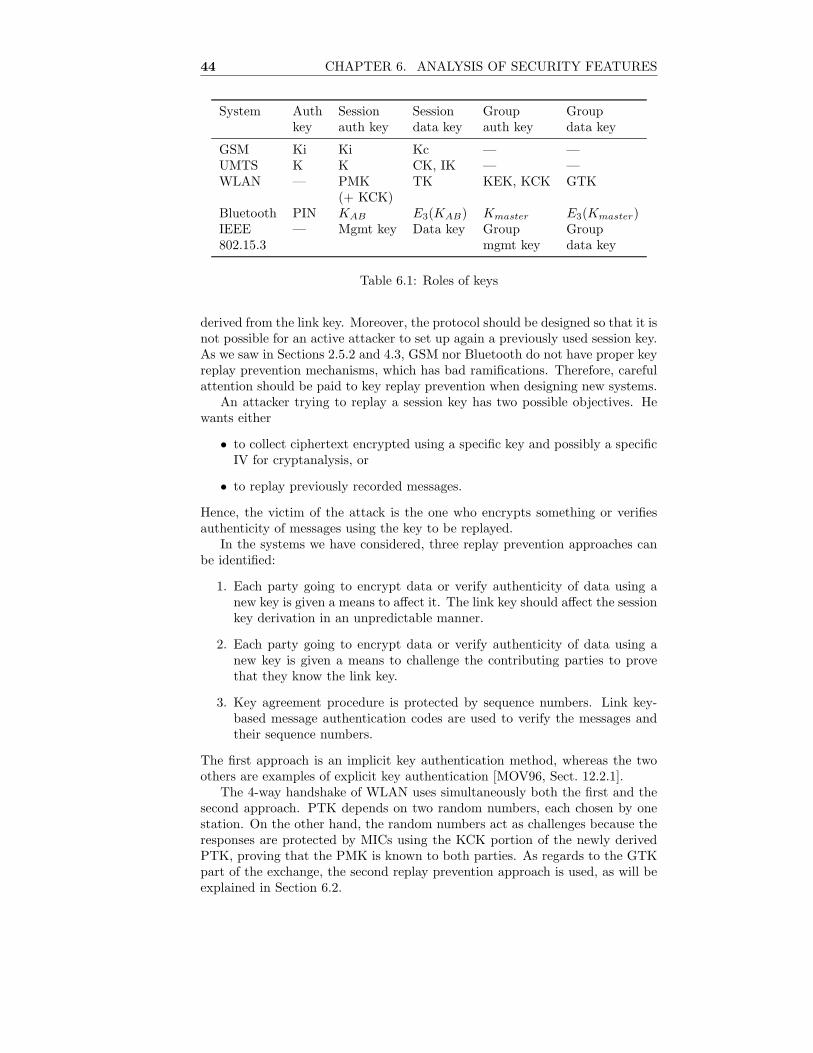
44 CHAPTER 6. ANALYSIS OF SECURITY FEATURES
System Auth Session Session Group Groupkey auth key data key auth key data key
GSM Ki Ki Kc — —UMTS K K CK, IK — —WLAN — PMK TK KEK, KCK GTK
(+ KCK)Bluetooth PIN KAB E3(KAB) Kmaster E3(Kmaster)IEEE — Mgmt key Data key Group Group802.15.3 mgmt key data key
Table 6.1: Roles of keys
derived from the link key. Moreover, the protocol should be designed so that it isnot possible for an active attacker to set up again a previously used session key.As we saw in Sections 2.5.2 and 4.3, GSM nor Bluetooth do not have proper keyreplay prevention mechanisms, which has bad ramifications. Therefore, carefulattention should be paid to key replay prevention when designing new systems.
An attacker trying to replay a session key has two possible objectives. Hewants either
• to collect ciphertext encrypted using a specific key and possibly a specificIV for cryptanalysis, or
• to replay previously recorded messages.
Hence, the victim of the attack is the one who encrypts something or verifiesauthenticity of messages using the key to be replayed.
In the systems we have considered, three replay prevention approaches canbe identified:
1. Each party going to encrypt data or verify authenticity of data using anew key is given a means to affect it. The link key should affect the sessionkey derivation in an unpredictable manner.
2. Each party going to encrypt data or verify authenticity of data using anew key is given a means to challenge the contributing parties to provethat they know the link key.
3. Key agreement procedure is protected by sequence numbers. Link key-based message authentication codes are used to verify the messages andtheir sequence numbers.
The first approach is an implicit key authentication method, whereas the twoothers are examples of explicit key authentication [MOV96, Sect. 12.2.1].
The 4-way handshake of WLAN uses simultaneously both the first and thesecond approach. PTK depends on two random numbers, each chosen by onestation. On the other hand, the random numbers act as challenges because theresponses are protected by MICs using the KCK portion of the newly derivedPTK, proving that the PMK is known to both parties. As regards to the GTKpart of the exchange, the second replay prevention approach is used, as will beexplained in Section 6.2.

6.1. SESSION KEY ESTABLISHMENT 45
4-way handshake is not very economical protocol as it uses two differentprotection methods, even though either of them would be sufficient. Moreover,the last message of the exchange seems a bit futile. Essentially, the sole contentof the message is the MIC, which proves that the authenticator knows the correctKCK. However, has this not already been proven earlier, in the second message?So the last message appears to be a kind of acknowledgement indicating that thethird message was received. Another, more efficient approach would be to useonly a negative acknowledgement to initiate retransmission when the previousmessage was lost, if this was the case.
An example of the third approach can be seen in the AKA procedure ofUMTS. The challenge that effectively determines the key is protected by AUTN,including a sequence number and an authentication code based on the identifi-cation key. The USIM can then verify that the challenge is fresh and was reallygenerated by its own AuC.
6.1.1 Key Replay Attack on IEEE 802.15.3
Also IEEE 802.15.3 uses the third method to protect key distribution. The KOunilaterally determines the key but it must calculate a message authenticationcode in order to convince the recipients. The superframe number acts as thesequence number. The superframe number is required to be strictly increasingand in the case it is not, the beacon and related frames are rejected [IEEE03a,Sect. 9.3.6].1
However, the replay prevention mechanism is not perfect. Consider thefollowing quotation from [IEEE03a, Sect. 9.1.7]:
To prevent replay of old messages, a strictly-increasing time tokenis included in the beacon. A DEV may reject as invalid a receivedbeacon with a time token less than or equal to the current timetoken. In addition, the time token is included in the CCM nonce,as described in 10.2.4, for each secure frame, as described in 7.2,so the integrity check will fail if a frame is replayed in a differentsuperframe. A DEV in a secure piconet maintains two values forfreshness. The CurrentTimeToken is the time token value found inthe beacon for the current superframe and is used to protect all mes-sages sent and check all messages received during that superframe.The LastValidTimeToken is used by the DEV to ensure that thesecurity of the beacons have [sic] not been compromised.
So what about replaying messages during the same superframe? This possibilitywill be explored in Section 6.3.2. Indeed, the duration of one superframe ispretty short, so as regards to key replay attacks, this is not a big securityproblem. But there is another more serious shortcoming in the replay preventionmechanism. Consider the following scenario:
1. Device A joins a piconet, the PNC of which is device B.
1Although stated clearly in [IEEE03a, Sect. 9.3.6], there is a clause in [IEEE03a, Sect. 9.1.7]implying that rejecting superframes with an invalid time token is optional because it uses theword may instead of shall. It is a little dangerous to include this kind of misleading clauses ifsecure implementations are desired.

46 CHAPTER 6. ANALYSIS OF SECURITY FEATURES
2. An adversary, operating device C, observes a key distribution message sentto device A by device B. (Device B is assumed to be the KO.) He alsoobserves the related beacon frame, including its time token T .
3. Device A leaves the piconet.
4. Later, device A wishes to join the piconet again. However, the adversaryimpersonates device B to device A and replays the beacon frame withtime token T . Device B has no other alternative than to initialize Last-ValidTimeToken to this value. Meanwhile, it may have been a memberof another piconet, so it does not remember the correct value for thisvariable.
5. Device C replays the key distribution message to device A before sendinga new beacon.
The consequence is that the MIC is correct and device A accepts the key,assuming that the management key has not been changed. This example showsthat using synchronized clocks as sequence numbers does not guarantee freshnessunless the key is renewed between losses of synchronization or further actionsare taken to handle the situation properly.
6.2 Multicast Communication
All systems we have studied enable sending messages targeted to more than onereceiver. In GSM and UMTS, this is limited to base stations broadcasting ormulticasting messages to MSs. GSM networks use a special-purpose channelfor broadcasting control messages [ETSI00c], but UMTS even allows multicasttransmission of user data using the BMC protocol, as noted in Section 2.1.2.Nevertheless, all these messages are unencrypted, hence there are no groupkey management mechanisms. IEEE 802.15.4 allows encryption of broadcastmessages, but since there is no management for unicast keys, there is no suchthing for group keys either. It is up to the upper layers to provide such keys.
In contrast, the rest of the systems we have studied do have mechanisms forgroup key management. IEEE 802.15.3 has completely separate managementfor point-to-point and group keys. Bluetooth has separate keys for these do-mains too, and session keys are derived using the respective link key. However,distribution of temporary group keys (master keys) is protected by the current(point-to-point) link key, so they are not completely independent.
A more significant difference between Bluetooth and IEEE 802.15.3 is thatBluetooth specifies that only one link and encryption key can be active andthere are procedures for switching between combination keys and group keys.This has some implications on security, and they are discussed in Section 6.2.2.
In Bluetooth, transmission of the temporary group key is protected by thecurrent link key. This would indeed be susceptible to replay attacks unlessmutual authentication was not mandated after that, verifying that the masterknows the new link key. Now it can be seen that including the claimant ad-dress to the authentication response computation is vital. Otherwise, as severalslaves share a common link key, a master impersonator could perform a reflec-tion attack by forwarding challenges from one slave to another and receiving

6.2. MULTICAST COMMUNICATION 47
the correct response without knowing the link key. However, executing the mu-tual authentication procedure is not good enough, since the transition from thetemporary group key to a group encryption key is not protected.
WLAN has a bit similar hierarchy with respect to group keys. Transmis-sion of GTKs, the group encryption keys, is encrypted by the KEK portion ofthe PTK. The GTK distribution part of the 4-way handshake obeys the sec-ond replay prevention method. The message containing the encrypted GTK isprotected by a MIC calculated under the KCK. The random number (SNonce)supplied by the supplicant in the second message acts as a challenge, since itaffects the KCK.
In addition, GTK can be renewed without changing the PTK, that is, re-executing the 4-way handshake. The group key handshake protocol uses theold KCK and KEK to protect transmission of the new GTK. Since no newchallenge is supplied by the receiver, it might seem that replay attack would bepossible. However, group key handshakes are protected by 64-bit sequence num-bers [IEEE04, Sect. 8.5]. In other words, they use the third replay preventionmethod of Section 6.1.
It is interesting that there is a separate handshake procedure for changing theGTK but changing the TK implies changing also the GTK. This feature wouldbe justified if multicast packets were sent significantly more frequently thanunicast packets. However, this is probably not the case in most applications,and this procedure just complicates the RSNA implementation.
6.2.1 Common Group Keys
An important thing to discern about all the WPAN systems discussed here isthat they use common group keys. This enables all group members to imper-sonate any other member of the group when sending multicast messages. Thisis even possible in WLAN although each station has its own GTK. But sinceGTKs are communicated to other stations to allow them to decrypt and verifyauthenticity of messages, they can also use it in impersonation attacks.
Solving this problem would mean enabling others to decrypt and verify au-thenticity without the ability to encrypt or calculate authentication codes. Inpractice, this would mean employing public key cryptography [Sti02, Sect. 5.1],which is not usual in radio systems. Of course, public key methods would call forfar more computing capacity from the hardware than the symmetric methods.
Since this is the case, it may seem odd that there are separate group keys foreach WLAN station. Maybe the designers thought that it would help migratingto public key algorithms in future. Or maybe they just wanted to avoid acomplex protocol for common key agreement. Bluetooth and IEEE 802.15.3networks are centrally coordinated piconets and the group keys are issued by thecoordinator, but in ad hoc WLANs, there is no such coordination, so commonkey agreement is not a trivial problem. In infrastructured mode, there is acommon AP, but in that case, only one group key is actually used as pointedout in Section 3.2.
6.2.2 Bluetooth Master Keys
If temporary master keys are used to protect Bluetooth broadcast transmissions,also unicast messages must be encrypted using the common key. This is justified
48 CHAPTER 6. ANALYSIS OF SECURITY FEATURES
by assessing that some devices might be incapable of switching between the keysin real time, after examining the packet header [Blue03b, Part H, Sect. 3.2.6].In my opinion, this is quite a big sacrifice in terms of security, since it allowseavesdropping of unicast traffic by other members of the piconet for the timethe temporary key is enabled, that is, as long as encryption mode 3 is used.
Can this problem be solved, assuming that there really are such deviceswith limited capabilities? Consider how such devices would be used in theIEEE 802.15.3 system. In that system, it is allowed to use the group encryptionkey if no point-to-point security association exists. Using these keys for allunicast traffic is equivalent to the Bluetooth encryption mode 3. Limited devicescan do so, but they are still subject to eavesdropping by other piconet members.However, the other devices can still use point-to-point keys if they choose to doso, whereas in Bluetooth, all devices are deprived the ability of using such keysdue to the possibility of having some limited-capability devices in the piconet.
To defeat this disadvantage, I propose that fourth encryption mode be de-fined. It would be named “Point-to-point and broadcast encryption using dis-tinct keys,” and it would allow using different encryption keys for unicast andbroadcast messages. The point-to-point key could be derived from the old linkkey that must be saved anyway, for example. This would be fully compatiblewith the current specifications. However, a negotiation mechanism should beinserted to the LMP, by which the master could find out whether the device iscapable of using two encryption keys simultaneously.
6.3 Inputs to Protection Functions
As we have seen, the outputs of encryption and integrity protection functionsdepend on various inputs, in addition to the session key and the data to beprotected. The primary reason for this is to avoid using the same keystreammore than once. As noted in Footnote 6 of Chapter 2, reusing keystreams revealspartial information about the plaintext to an eavesdropper. Another reason ismessage replay prevention. This section analyzes what kind of inputs should beused to achieve security.
6.3.1 Counters versus Random IVs
There are systems employing IVs that are not required to be strictly increas-ing. One example is WEP, the original WLAN data protection protocol. Someimplementations used a counter value as the IV, but that was not mandatory.Using mere random numbers would have been perfectly compliant with thespecifications.2
However, using counters has a couple of advantages over using random IVs.One of them is that the same counter can also be used to prevent active attackersfrom replaying previously recorded frames, in addition to ensuring keystreamunicity. If the integrity checking code depends on a strictly increasing counter
2In fact, it was not even required that the IV should be changed for each frame. It wasonly stated that IV be changed adequately often, depending on the protocols used at upperlayers. This fact alone is in direct contradiction with the clause in the specifications statingthat WEP is “reasonably strong.” [IEEE99, Sect. 8.2]

6.3. INPUTS TO PROTECTION FUNCTIONS 49
included in frames, replayed frames can be detected and discarded. Even if in-tegrity protection is not applied, counter-dependent encryption makes it difficultto replay messages.
Another reason why counters are better is that for the same level of security,you would need a random IV that is much longer than the counter would be.This is due to the birthday paradox. If we use counter having length of NC bits,we know that the same value will occur exactly after 2NC messages. Thus,2NC + 1 consecutive values are needed for a collision to occur. But when usingrandom IVs, we can never know when a specific value appears next time. Itcan only be shown that if we have q randomly chosen values from M differentpossible values (with uniform distribution), then with probability ε there are atleast two values that are equal to each other when
q ≈
√
2M ln1
1− ε(6.1)
The proof can be found in [Sti02, Sect. 4.2.2]. So if we want to achieve the samelevel of security with random IVs as with an NC-bit counter, let us substituteq by 2NC . Let NIV denote the length of the corresponding IV, that is log2 M .After these substitutions the above equation takes the following form:
2NC ≈
√
2NIV +1 · ln1
1− ε(6.2)
Taking base 2 logarithms, this yields
NC ≈1
2
(
NIV + 1 + log2 ln1
1− ε
)
(6.3)
Solving for NIV gives
NIV ≈ 2NC − 1− log2 ln1
1− ε(6.4)
Had we used counters, we would still have probability zero for collisions whenq = 2NC . It is not possible to attain this level of security by any finite-lengthrandom IV because
limε→0+
NIV = 2NC − 1− limε→0+
log2 ln1
1− ε=∞
Anyway, even ignoring the last term in Equation (6.4), it can be seen that thelength of a random IV must be at least about two times that of a counter.Hence, counters are more economical than random IVs and should be preferredin future systems. However, it should be noted that certain modes of operationrequire IVs to be randomly chosen as explained in Chapter 7.
All systems we have studied use counter-based initialization. Table 6.2 sum-marizes what additional inputs to protection functions are used in the systemsstudied in previous chapters. It also shows the role each input is playing. Theremaining part of this section concentrates on analyzing the purpose of theseadditional inputs.

50 CHAPTER 6. ANALYSIS OF SECURITY FEATURES
System Channel Counter Direction Counter skew Otherprevention
GSM Physical layer Split key- — —TDMA frame # stream
UMTS Bearer ID Packet # Input to FRESH —f8 & f9 (f9 only)
WLAN Priority Packet # Trnsmtr — —addr
Bluetooth — Master’s clock — Master’saddr
IEEE — Superfrm #, Src ID, — —802.15.3 Packet #, Dest ID
Frag ctrlIEEE — Key #, Src — —802.15.4 Packet # addr
Table 6.2: Additional inputs to data protection functions
6.3.2 Packet Counters
All these systems include some kind of counter in keystream generation toachieve the aforementioned security goals. It is either a packet sequence num-ber transmitted in cleartext with the packet, or a physical layer frame numberor another value known to both communicating parties by synchronization ofclocks.
IEEE 802.15.3 uses counters of both types. The superframe time token isdetermined by synchronization whereas the packet number, officially called Se-cure Frame Counter (SFC), is prepended to the encrypted payload [IEEE03a,Sect. 7.2]. Although not mandated, SFC can be reset to zero when the super-frame changes [IEEE03a, Sect. 7.2.7.3]. The specifications are obscure aboutwhether SFC values should be distinct for different fragments of a single SDU.When discussing the nonce value, they say [IEEE03a, Sect. 10.2.4]:
In order to preserve the security of the symmetric algorithms, thisnonce shall be unique. As a result, the DEV shall not reuse any2-octet sequence number within a single superframe that is intentedfor a particular DEVID (as this would cause a repeated nonce).
However, the nonce depends also on the fragmentation control field in the MACheader. This field includes a third counter, namely the fragment number. Hence,it seems that the same SFC value could be used. Including the fragment numberto the nonce implies that using the same SFC does not yield identical noncesfor different fragments of one SDU.
As speculated in Section 6.1.1, it might be possible to replay IEEE 802.15.3frames during the same superframe under which they were sent. The specifica-tions state nowhere that the value of SFC also be checked, to ensure that novalue has been used more than once. However, the fragmentation control fieldaffecting the nonce includes also an SDU sequence number that is used to detectduplicate transmissions of SDUs or fragments thereof [IEEE03a]. Inclusion ofsuch data to the nonce might seem to exclude any possibility for packet replay.

6.3. INPUTS TO PROTECTION FUNCTIONS 51
However, the length of that sequence number is only 9 bits, and it might wellroll over during a superframe. If that was not possible, it would have beenpointless to introduce the SFC at all. In fact, in [IEEE03a, Sect. 10.2.4] it issaid that keystream unicity is guaranteed unless more than 216 frames are sentto a single destination during a superframe, so it is reasonable to assume thatthe number of frames is not limited to 29. This being the case, it is strange thatthere is no protection against SFC replay. Such functionality could easily havebeen implemented in several ways, as will be shown in Section 6.4.
In addition to having strictly increasing packet number counters, the WLANRSNA definition and IEEE 802.15.4 require that no counter value is used twice.In practice, this means changing the session key when the counter rolls over.In theoretical point of view, this is the right thing to do, to absolutely refrainfrom reusing counter values with the same key. In a way, the packet countermeasures the usage of the corresponding key. The other systems do not havethis kind of property, however. In IEEE 802.15.3, the functionality of measuringkey usage would be attainable if the counter was longer than 16 bits and it wasnot allowed to reset it when the superframe changes [IEEE03a, Sect. 7.2.7.3].If that was the case, the time token could be removed from the nonce, had thereplay prevention mechanism been designed properly.
The IEEE 802.15.4 specification does not too much elaborate the very essenceof the key sequence counter. Having read the definition of that parameterin [IEEE03b, Sect. 7.6.1.8], one can think that it could be used as an extension ofthe frame sequence number in case of roll-over. But why then have two distinctcounters instead of one 40-bit counter? Or perhaps the key sequence countercould be used to prevent key replay attacks on a higher layer key distributionprotocol, together with an authentication code. However, such functionalityshould be included to the respective layer to promote layer independence.
In WLAN headers, there is a field named Key ID, which is used to facilitatethe transition to a new group key or allow switching between several WEPkeys [IEEE04, Chpt. 8]. Footnote 8 of Chapter 2 mentioned KSI, which is thereto help avoiding key inconsistencies after UMTS handovers. In GSM, there isa value with a similar function, namely the Ciphering Key Sequence Number(CKSN) [ETSI00a]. However, the IEEE 802.15.4 key sequence number doesnot compare well with CKSN, KSI, or WLAN Key ID, since it is completelyomitted in CBC-MAC mode. Hence, its purpose may have something to dowith keystream reuse avoidance.
The fact that the sequence numbers are omitted in CBC-MAC mode ofIEEE 802.15.4 implies that there is no frame replay protection in that mode.The attacker cannot forge an arbitrary message but he can replay any messagehe has previously seen.
6.3.3 Maintaining Parallel Counters
Another component that seems to be present in every system is some direction-dependent action or value supplied to the keystream generator, or the integrityfunction if there is one. Various methods are used. GSM uses different portionsof the keystream for uplink and downlink, whereas in UMTS, there is a specialinput bit to the cryptographic algorithms. In Bluetooth, no separate action isneeded, since the clock used as a counter input determines the direction of trans-mission. In addition, only one device can send during a single timeslot [Blue03b,

52 CHAPTER 6. ANALYSIS OF SECURITY FEATURES
Part B, Sect. 8.6], so common temporary keys are neither a problem.WLAN uses the transmitter address field to differentiate the nonce between
the directions. This is essential only in unicast transmissions, since for grouptransmission every station has its own GTK. Similarly, IEEE 802.15.3 andIEEE 802.15.4 use the source identifier to achieve the same effect. However,IEEE 802.15.3 also takes the destination identifier into account. The reason forthis is that in IEEE 802.15.3, it is allowed to use the common group encryptionkey if a point-to-point key does not exist. Therefore it may happen that thesame encryption key is used with packets sent to several different destinations.
In UMTS, there is an input called Bearer ID. It is necessary because theframe counters are maintained separately for different radio bearers, and thusthe same values of counters can be used more than once on different bearers. InGSM, the multitude of channels is not a problem because a single physical layerframe cannot contain data from more than one channel [ETSI00c]. As pointedout in Section 3.3, WLAN frame priority classes form logical channels havingseparate replay detection counters, and that is why the priority is used in nonceconstruction.3
Now comparing this to the direction-dependent inputs, we can see that thefundamental reason for having such inputs is that the frame counters are main-tained separately for both directions. Hence, they serve exactly the same pur-pose as the Bearer ID input in UMTS. All these inputs just distinguish betweendifferent counters used under a single encryption key, or hierarchies of suchcounters.
Why then have several parallel counters at all? There are two possibleapproaches to multiple channel access in radio systems: contention-based andcentrally coordinated scheme. There are systems that use only one of thesemechanism. For example in Bluetooth, only the centrally coordinated methodis present. On the other hand, some systems, such as WLAN [IEEE99, Chpt. 9],IEEE 802.15.3 [IEEE03a, Sect. 8.4], and IEEE 802.15.4 [IEEE03b, Sect. 7.5.1],use both. When contention-based access is allowed, there cannot be sharedframe counters between different stations.
Another reason might be layer independence. In UMTS, there clearly isa common reference clock at the physical layer, but as protection algorithmscan be applied two or three layers above the physical layer, it would not beconvenient to use such information. Moreover, having separate counters fordifferent radio bearers makes parallel protocol instances independent of eachother.
Although necessary to have separate counters at each WLAN station, itwould not be necessary to have separate counters for each security associationas required in [IEEE04, Sect. 8.3]. In principle, a transmitter could use a com-mon counter for all destinations, possibly made a few bits longer. However, thedrawback would be that all session keys would have to be renewed when thecounter rolled over, even if some of the keys were not used frequently, causingsuperfluous key exchange traffic. Thus the third good reason for having par-allel counters is that distinct counters for different session keys can be used todetermine when the key be changed.
3If priority was not used in nonce construction, an attacker might try to replay a frame in alower priority class. However, this could be prevented also by authenticating the priority classinformation itself. But as the specification does not define how that information is signaled,the approach used here is probably the better alternative.

6.3. INPUTS TO PROTECTION FUNCTIONS 53
Fourth reason for parallel counters was already discussed in Section 3.3.Having several priority classes necessitates reordering of frames, which in turnnecessitates separate counters for each class. It is worth noting that the WLANspecification rules that there is only one transmission counter that is commonfor all priority classes [IEEE04, Sect. 8.3]. In theory, there could be separatetransmission counters too. That would make it possible to use the session keyseven longer if the classes were used evenly. Indeed, having more counters wouldcomplicate the implementation, which was probably the reason for the decision.But I see no reason why that could not have been made optional.
IEEE 802.15.3 does not mandate maintaining a distinct counter for all des-tinations although it is possible even with the group key due to the destinationidentifier input to encryption [IEEE03a, Sect. 10.2.4]. There seems to be noreason for using a distinct counter for each security association because a 16-bit counter is not long enough to be used as a basis for determining when torenew the key. Replacing the destination identifier by additional counter bitswould have been more efficient. Then there would be more nonces available fora single destination if the other destinations were not sent to so often. In fact,IEEE 802.15.4 allows using a common default encryption key4 and solves theproblem in this manner, that is, by using a common 32-bit counter [IEEE03b].
It might be, however, that the source and destination identifiers are includedalso to impede precomputation attacks on encryption using the group key. Nowan attacker has to compute separate lookup tables for each source–destinationpair he wishes to attack on, instead of just one common table. More informationabout attacks of this kind can be found in [WHF03, Sect. 5].
6.3.4 Counter Initialization and Reset
Usually packet sequence number counters are initialized to zero when a newsession key is established. However, UMTS allows UEs to unilaterally choose theinitial counter values after handovers, arbitrarily many times during the lifetimeof the key. This would be dangerous if the FRESH parameter, a random valuechosen by the RNC, was not there. Otherwise an active attacker could rewindthe counter and replay previously recorded messages, but now the 32-bit valueof FRESH is different from the previous value with an overwhelming probabilityand replay attacks are not likely to succeed.
So if the message originator is able to decrement the counter values, thereceiving party must be given an opportunity to affect the value of the integrityprotection function, at least as often as counter values are adjusted. As regardsto decrementing the encryption counter, the situation is just the opposite. Themessage sender should provide randomness to keystream generation if the re-ceiver could decrement the counter. This is necessary to prevent the receiverfrom collecting two or more ciphertexts encrypted using the same keystream.Note that this is not needed in UMTS, since performing a successful handoverby itself apparently requires being able to calculate valid integrity codes underthe new FRESH value [3GPP04h].
Also GSM allows continuing the use of the same session key after a handover,since the security context can be communicated between MSCs via a common
4This default encryption key is the same key that is used to protect broadcast frames,including beacon frames.

54 CHAPTER 6. ANALYSIS OF SECURITY FEATURES
VLR, and also within an MSC area [ETSI00e]. GSM uses the clock of the basestation as the frame counter, the MS’s clock being synchronized with it. Sowhat can be said about handovers? Is it possible for the new base station toskew the clock? The answer is yes, since the clocks of different base stationsare not required to be synchronized with each other. In fact, the clocks maydiffer even in different cells served by a single base station [MP92, Sect. 9.4.2.3].By considering the rule stated in the preceding paragraph, a problem can beidentified. An attacker impersonating a base station can rewind the clock andreceive ciphertext encrypted by a previously used keystream.
The other systems we have studied do not define handover mechanisms — atleast yet. But if such mechanisms are introduced some day, which seems prettylikely especially with WLAN, this is an issue not to be forgotten.
Note that the non-existence of a FRESH-style input parameter is the funda-mental reason for the flaw in the IEEE 802.15.3 key distribution protocol thatwas revealed in Section 6.1.1. There is no actual handover procedure, but theloss of synchronization due to leaving the piconet for a while causes a similareffect. If devices were allowed to submit a random parameter affecting the MICcalculation every time they joined the piconet, a KO impersonator would not beable to replay the key. It is important to discern that the attack is not limitedto replaying key distribution messages. If the attacker manages to rewind thetime token and set up the same session key, nothing prevents him from replay-ing SDU and command frames too. Moreover, by these actions the attacker canforce the other party to encrypt messages using previously used keystream.
The attack discussed above is also well applicable on Bluetooth. As shownin Section 4.3, replaying the encryption key is possible. Indeed, the speci-fication forbids the master to adjust the clock during the existence of the pi-conet [Blue03b, Part B, Sect. 1.1]. The slave can possibly detect drastic changesin the clock of the master, but after visiting another piconet, there is no wayfor the slave to know if the clock has been skewed. Requiring mutual authen-tication does not help. Since the authentication function E1 does not dependon the clock, the attacker can perform the reflection attack, that is, imperson-ate the victim to the real master to obtain the correct response. After that,the attacker is free to replay any previously recorded frame at the appropriatetimeslot. He may also receive packets encrypted using an old keystream. Notethat Gauthier’s attack mentioned in Section 4.3 is a special case of this attack.
We can see that the objectives of these counter skew attacks are to
• obtain partial information (xor sums) of plaintexts, or
• replay previously recorded messages.
In fact, these are quite similar to the goals of key replay attacks listed in Sec-tion 6.1. The only difference is that an attacker performing key replay attacksmight have also other means for cryptanalysis than exploiting partial knowledgeof plaintexts.
6.3.5 Classification of Inputs
There is one seemingly useless input to the Bluetooth encryption algorithm. Us-ing the master’s device address in Bluetooth encryption does not affect anything,since it is a constant and thus is a useless input. With this exception, we can

6.4. SELECTIVE ACKNOWLEDGEMENT AND RETRANSMISSION 55
see that additional inputs are all about counters. Counters prevent keystreamreuse and message replay when properly amended by some additional variables.We can see that each useful input value is of one of the following types:
Counter (CTR) that is incremented after one frame or fragment thereof hasbeen sent, or when another counter rolls over. Alternatively, counters maybe based on synchronized clocks.
Counter Identifier (CID) that combined with the other inputs of this typeuniquely identifies the set of counters, the values of which have been usedas input.
Counter Skew Guard (CSG) that provides protection against replay attackswhen one communicating party is able to unilaterally reinitialize countersduring the lifetime of the session key.
Table 6.3 shows the roles of the different useful inputs according to thisclassification.5 The direction “input” to the GSM keystream splitter is classifiedas a counter. As an uplink timeslot always follows the downlink timeslot withthe same number after a period corresponding to three timeslots [ETSI00c], thedirection can be viewed as a one-bit subcounter of the actual frame number. Asregards to IEEE 802.15.3, it is good to note that the CIDs distinguish only thepacket and fragment counters. The superframe counter is common to the entirepiconet.
Not all inputs that do not belong to the aforementioned classes are com-pletely useless. For example in CCM mode, the length of the nonce cannotbe chosen independently but rather depends on the choice of another param-eter [WHF03, Sect. 2]. In this case, it is better to include some variable datainstead of a constant to impede precomputation attacks mentioned in Sec-tion 6.3.3.
6.4 Selective Acknowledgement and Retransmis-
sion
We have seen that using message authentication codes does not by itself ensurethat the message was sent by the correct party. At most, a valid code indi-cates that a similar message has been generated by that party at some point oftime, but it does not exclude the possibility of an attacker having replayed themessage.
It is interesting that the need for protecting against replay attacks is men-tioned in [Dwo04, Sect. B.1]. Nevertheless, it is not said that sequence numberscould be used to defend against message replay. It is neither said that CCMnonces could be constructed using sequence numbers, not to mention that thesame numbers could be used for both purposes, although this is the most com-monly used approach in the recent specifications.
However, requiring strictly increasing sequence numbers for replay preven-tion is somewhat conflicting with the idea of burst transmissions, meaning that
5In addition to the master’s address input to the Bluetooth encryption, the key sequencenumber of IEEE 802.15.4 has also been omitted, since no security reasons for its inclusionwere found.

56 CHAPTER 6. ANALYSIS OF SECURITY FEATURES
System Input Type
GSM Frame number CTRDirection CTR
UMTS Packet number CTRDirection CIDBearer ID CIDFRESH CSG
WLAN Packet number CTRTransmitter address CIDPriority CID
Bluetooth Master’s clock CTR
IEEE 802.15.3 Superframe number CTRPacket number CTRFragmentation control CTRSource identifier CIDDestination identifier CID
IEEE 802.15.4 Packet number CTRSource address CID
Table 6.3: Classification of additional inputs
several packets are sent successively, without requiring acknowledgement be-tween them. After the burst, the receiver indicates which packets were notreceived successfully, resulting in retransmission of those packets. This kindof selective acknowledgement and retransmission puts the packet numbers outof order. One possible solution is to renumber the packets before retransmis-sion, but that would necessitate re-encryption of the packets too if encryptiondepended on the same packet number. If separate numbers were used, the in-tegrity code would still have to be recomputed. Due to the additional workloadand power consumption caused by re-encryption or MIC recomputation, thissolution is often undesirable.
We have studied four systems having a real message authentication mecha-nism. Two of these, WLAN [IEEE99, Chpt. 9] and IEEE 802.15.4 [IEEE03b,Sect. 7.5.6], do not involve burst-type transmissions. The RLC protocol ofUMTS provides selective acknowledgements, but as replay protection is per-formed at the RRC layer, different sequence numbers are used for these pur-poses, thus eliminating the need for re-encryption [3GPP03b, 3GPP04h]. Thisworks because the original packet order is restored before replay filtering.
As mentioned in Section 6.3.2, the intra-superframe replay prevention mech-anism of IEEE 802.15.3 is deficient. It would have been possible to make it morecomplete for the following reasons, even either of them being sufficient:
• the SFC is incremented on frame retransmission, and
• the order of SDUs is preserved by the MAC layer (although they arenecessarily not transmitted in that order).

6.4. SELECTIVE ACKNOWLEDGEMENT AND RETRANSMISSION 57
Incrementing the SFC implies that the standard replay counter solution wouldwork, one counter per sender being adequate. [IEEE03a]
However, incrementing the SFC necessitates re-encryption of retransmittedframes. Had this requirement been omitted, incorporating replay protectionwould still have been relatively easy due to the SDU order preservation prop-erty. More precisely, there can be different streams of data, such that the orderis preserved within them, whereas the order is not necessarily preserved withrespect to other streams [IEEE03a]. The streams form logical channels in a sim-ilar fashion to the WLAN priority classes.6 Therefore, defining one SFC replaycounter for each stream, just like they have their own SDU number counters,would have prevented SFC replay. If this solution had been used, the replay fil-tering should have been performed after order restoration, of course. Note thatthe stream index (identifier) field is part of the MAC header [IEEE03a, Sect. 7.2]and thus authenticated, so it would not have been possible to replay frames ondifferent streams. Nevertheless, the most elegant solution would perhaps havebeen to make the SDU numbers longer than 9 bits, forget separate SFCs, andinclude the stream index to the nonce as a CID-type input, to prevent messagereplay on different streams.
Note that if incremented on retransmissions, SFC would no longer verifythe correct position of the SDU in the stream. Therefore, inclusion of the SDUnumber to the nonce or at least authenticating it would be important in orderto enforce SDU order preservation.
6.4.1 Replay Detection Algorithm with Memory
The aforementioned solutions do not work, if in-order packet transmission isnot available. What is the correct way to handle replay protection of bursttransmissions in such a case? Consider the following solution: In addition tomaintaining a register containing the SFC of the packet last received (denotedby N), a b-bit register s is used to keep track of the used SFC values. Notethat implementing the selective acknowledgement protocol itself requires usinga similar register to keep track of the lost packets, so this is not a big tradeoff.We denote the ith bit of s by si, and s ¿ n refers to the shift left operation,after which si contains the value stored at si−n before the operation if i ≥ n.Otherwise si is set to 0. Suppose that N and all si are initialized to 0. Onreceiving a packet with SFC p, the algorithm shown in Figure 6.1 is executed,in order to decide whether the packet should be accepted or rejected. Thealgorithm returns Accept when the SFC is greater than any previous SFCvalue, or SFC is within the window of size b and it has not been used before.Otherwise, the algorithm returns Reject. We will call this solution the ReplayDetection Shift Register (RDSR).
Note that it is important to verify the authenticity of the received framebefore the registers are updated. Otherwise there would obviously be roomfor a DoS attack. The authenticity can be verified before executing the RDSRalgorithm but it might be more efficient to do it just before updating s and N . Ifthe authenticity check failed, the algorithm execution should be aborted and theframe rejected. This problem that the SFC value needs to be verified efficiently
6The specifications use term stream when referring to isochronous data streams. In ad-dition, the normal asynchronous data flow forms an additional logical channel although notcalled a stream. However, in this discussion, term stream refers also to this channel.

58 CHAPTER 6. ANALYSIS OF SECURITY FEATURES
if p > N − b thenif p > N then
s¿ (p−N)N ← p
endifif sN−p = 0 then
sN−p ← 1return Accept
endifendifreturn Reject
Figure 6.1: RDSR algorithm
before replay counters are updated is not unique to the RDSR algorithm butcommon to all replay detection mechanisms based on sequence numbers.
6.5 Scope of Encryption and Authentication
Having examined some systems, we have seen that some data are encrypted andauthenticated, whereas other data might not be protected at all. Yet there aredata that are authenticated but not encrypted and vice versa. Table 6.4 showshow different types of data are treated in the systems we have considered. Notethat data related to session key and group key exchange are omitted in thefollowing discussion, since they were already analyzed in Sections 6.1 and 6.2.In addition, messages and data related to error detection and correction as wellas synchronization are not considered here either.
The common thing to all systems is that the data provided by upper layers(SDUs) can be encrypted. Usually, authentication is also applied if an appropri-ate mechanism exists in the system. However, UMTS does not apply authen-tication to user data although there is a mandatory-to-implement protectionfunction. Only control data transmitted using RRC are authenticated.
Link layer commands are usually authenticated, or at least encrypted ifauthentication is not used in the system. WLAN is an exception, since authen-tication and encryption is applied only to data frames, even if RSNAs are used.This may be due to the attempt to make TKIP resemble WEP as much aspossible, in order to facilitate upgrading legacy devices to use TKIP. Althoughthere is no protection for MAC commands, one could argue that security hasnot been cut down too much because by forging such commands, an attackercould only perform DoS attacks. Such attacks could also be executed usingradio jamming anyway, as noted in Section 1.2.
On the other hand, in mobile telephony systems, it is more important toprevent abuse of control messages, since they are used to control the servicethe subscriber is receiving. The executed phone or data calls are charged tothe users, so one could gain financial advantage by forging control messages. InUMTS, this has been handled properly, but GSM lacks decent authenticationof control messages.
MAC headers and flow control data seem to be always left unencrypted.

6.5. SCOPE OF ENCRYPTION AND AUTHENTICATION 59
System Unprotected Authenticated Encrypted Encrypted andauthenticated
GSM Stealing flags User dataCtrl data
UMTS MAC hdrs User data RRC cmdsFlow ctrl
WLAN MAC hdrs MAC hdrs SDUsFlow ctrl of data PDUsMAC cmds
Bluetooth Packet hdrs User dataFlow ctrl LMP cmds
L2CAP ctrl
IEEE MAC hdrs SDUs802.15.3 Flow ctrl
MAC cmds
IEEE MAC hdrs SDUs802.15.4 Flow ctrl MAC cmds
Beacon pld
Table 6.4: Scope of encryption and authentication
An eavesdropper observing the flow control data can only deduce that data arebeing sent and see if there is any congestion. This is not very useful information,since transmission of data could be observed even if flow control messages wereencrypted. IEEE 802.15.3 and IEEE 802.15.4 authenticate flow control data.Nevertheless, that is not very useful, since it offers protection only against onetype of DoS attack that could be carried out much easier by other means.
Since MAC headers are not encrypted in the IEEE systems, there is no pro-tection of location privacy because the MAC addresses are constant and theyidentify the device. Hence, an eavesdropper having receivers at several locationscould track the movements of particular users. In contrast, GSM [ETSI99b] andUMTS [3GPP03e] use temporary user identifiers in order to provide locationprivacy. However, the location privacy of GSM can be broken by impersonat-ing a base station due to the lack of control message authentication [WW02,Sect. 15.9.5].

60 CHAPTER 6. ANALYSIS OF SECURITY FEATURES

Chapter 7
Comparison of
Authenticated Encryption
Modes
Traditionally, block cipher modes of operation have defined how encryptionshould be applied when the length of the message is longer than the block sizeof the cipher. There are five such modes recommended by the US NationalInstitute of Standards and Technology: Electronic Codebook (ECB), CipherBlock Chaining (CBC), Cipher Feedback (CFB), Output Feedback (OFB), andCounter (CTR) [Dwo01]. However, ECB is known to be very insecure and israrely used in practice [Sti02, Sect. 3.7].
There are also some modes of operation for message authentication, such asCBC-MAC. Recently, many new modes of operation have been proposed thatcombine functionality for encryption and integrity protection. This chapterdiscusses and compares six such proposals. Table 7.1 shows the meanings of thesymbols used in the following discussion.
7.1 Offset-Based AE Modes
Charanjit Jutla proposed Integrity-Aware Parallelizable Mode (IAPM) [Jut01],providing both encryption and message integrity, and still being fully paralleliz-able, like ECB and CTR. Offset Codebook (OCB) [RBBK01] is a refinement ofIAPM.
Symbol Meaning
M MessageA AADN Noncen Block size of the cipher in bits|X| Length of X ∈ {M,A,N} in bits
Table 7.1: Notation used in discussion on modes of operation
61

62 CHAPTER 7. COMPARISON OF AE MODES
IAPM and OCB resemble the ECB mode, but they generate a random offsetfor each block that is xored to the input and the output of the cipher, signifi-cantly improving security. IAPM suggests two methods for offset generation:
1. Modulo-2 linear combinations of t =⌈
log2
(
|M |n
+ 2)⌉
vectors generated
using the block cipher.
2. Using modulo prime addition to generate the offsets from two vectorsgenerated using the block cipher.
OCB uses only an improved version of the modulo-2 generation method, requir-ing only one evaluation of the block cipher.
OCB has the following advantages over IAPM:
• Message length does not have to be a multiple of the block size of thecipher.
• IVs are not required to be randomly chosen but only unique.1
• No different key is required in offset generation.
• Offset generation based on modulo-2 arithmetics is far more efficient.
These differences make OCB more flexible, efficient, and suitable for wirelesscommunications systems.
To authenticate messages, IAPM basically calculates a xor-sum of the plain-text blocks and encrypts it using an offset vector. OCB has some special han-dling with respect to the final block, but essentially it uses the same mechanismto compute the authentication tag. As noted in Footnote 4 of Chapter 4, thiskind of action does not by itself ensure authenticity. However, it has beenshown that if the encryption function is assumed to be a strong pseudo-randompermutation (SPRP),2 then authenticity is achieved [BR00, Sect. 4].
7.2 Extensions of CTR Mode
Patents have been filed covering both IAPM and OCB. This has motivated de-velopment of patent-free authenticated encryption modes. These modes usuallyhave been extensions of the CTR mode. One such mode was CCM, which hasbeen adopted to several IEEE standards. In fact, OCB appeared in early ver-sions of IEEE 802.11i draft standard but was later replaced by CCM partlydue to these intellectual property issues [SE02, Cio02]. CCM combined theCTR mode and CBC-MAC to achieve authenticated encryption. CCM alsointroduced the possibility to include Additional Authenticated Data (AAD),such as packet headers, to the computation of the authentication tag.3 CCM isdescribed in more detail in Appendix A.
1In [Jut01], two approaches for generating t random vectors were proposed. It seems thatonly one of them really requires randomly chosen IVs, since the other way involves encryptingthe IV before using it as a counter.
2The notion of the SPRP property was introduced in [LR88, Sect. 4.4]. Originally, theproperty was called super pseudo-randomness but nowadays term strong is more common.
3Modes allowing inclusion of such data are sometimes referred to as AE with AssociatedData (AEAD) modes. Methods for converting AE modes into AEAD modes exist, and thereare such versions of both IAPM [HR03] and OCB [Rog02].

7.3. PERFORMANCE 63
Nevertheless, there were some shortcomings in the CCM mode. Phillip Rog-away (who had filed US Patent application covering OCB [USPt02]) and DavidWagner published a paper criticizing several aspects of CCM [RW03]. Later,they contributed to the development of a new mode called EAX [BRW04], of-fering the following improvements over CCM:
• Word Alignment (WA) is preserved. CCM prepends a few octets of lengthinformation to the AAD before applying CBC-MAC, in order to han-dle AAD with variable length properly. In contrast, EAX uses One-KeyCBC-MAC (OMAC), which is by itself secure for arbitrary-length mes-sages [IK03], unlike the standard CBC-MAC [BKR00, Sect. 5].
• EAX is on-line in the sense that the length of the message does not haveto be known in advance to start processing.
• Static AAD can be preprocessed, since the processing does not depend onthe nonce.4
• EAX allows fast verification (without decrypting the message) becauseOMAC is applied to the ciphertext instead of the plaintext.
EAX did not, however, solve the real problem of CCM: CBC-based authen-tication is not parallelizable and thus not suitable for high-speed applications.The first parallelizable patent-free AE mode was the Carter–Wegman + CTR(CWC) mode [KVW04]. It uses CTR mode encryption combined to the univer-sal hash approach to message authentication suggested by Mark Wegman andLawrence Carter [WC81]. However, CWC uses one block of the keystream tomask the output of the hash function instead of a randomly chosen bit string(one-time pad). The CWC hash function is a polynomial function in a finitefield, enabling parallel evaluation using Horner’s rule. It has been shown to beAlmost Xor Universal (AXU) [Kra94, Sect. 2.2],5 which is a bit weaker notionbut still enough to provide integrity in practice.
The most recently proposed mode of operation is the Galois/Counter Mode(GCM) [MV04b]. It is pretty similar to CWC, except it uses polynomial hashingover GF (2n) instead of Z2127−1,
6 which obviously allows more efficient imple-mentations. Also the GCM hash function family has been proven to be AXU.The authentication codes of CWC and GCM are computed using the ciphertextblocks, like in EAX, thus allowing fast verification.
7.3 Performance
Table 7.2 summarizes the features of the modes discussed above. The followingdefinition applies to the row indicating the number of Block Cipher Evaluations(BCEs) per message:
BX =
⌈
|X|
n
⌉
where X ∈ {M,A,N}
4In this chapter, nonce refers to an IV that is not required to be random but only uniquewith respect to the key.
5In [Kra94], term otp-secure hash family was used.6CWC is defined for 128-bit ciphers only and therefore the hashing field is fixed.

64 CHAPTER 7. COMPARISON OF AE MODES
In other words, BX means the length of X in terms of the block size of thecipher. As regards to CCM, δ : Z264 → Z2 is a function of |A| and is not ofinterest here, since it does not significantly affect the number of calls. It can benoted that CCM and EAX are very inefficient, since they double the number ofblock cipher invocations by using CBC-based authentication codes, in additionto losing parallelizability.
GCM seems to use the lowest possible number of BCEs per message: oneevaluation per each message block and one for masking the output of the uni-versal hash function. CWC applies the block cipher also to the output of thehash function itself before masking. The aim is purportedly to distribute theoutput of the hash function uniformly over Z2128 . Otherwise, values belongingto Z2128 \ Z2127−1 would never occur. In particular, since the masking opera-tion is addition in Z128
2 , the MSB of the 128-bit authentication code would notdepend on the message at all but only on the key and the nonce, thus givinga forgery advantage to an adversary. This difference of one BCE may seem in-different but it is not. In pipelined hardware implementations, a stall is causedby this extra evaluation because it depends on the results of the BM previousevaluations [MV04a, Sect. 3.1].
It is clear that OCB is more efficient than IAPM and GCM is faster thanCWC. But how do OCB and GCM relate to each other in terms of performance?In hardware implementations, the same pipeline stall argument holds in favor ofGCM: In GCM, all BCEs are independent of each other, whereas OCB causeseven two pipeline stalls per message.7 As regards to software implementations,GCM outperformed OCB with respect to short messages, according to simula-tions by the authors of GCM. However, OCB was faster when encrypting longmessages. This observation is explained so that GCM is faster due to using oneBCE less than OCB, but computing the hash function is more expensive thansimple modulo-2 addition, so with long messages OCB comes off better. [MV04a,Sect. 3]
It should be noted, however, that GCM implementations used in the testscited above used time–memory tradeoffs to speed up computing the hash func-tion, as recommended by the GCM specifications. The specifications even admitthat if no key-dependent memory is used, the hash function computation gen-erally takes even more time than running AES [MV04b, Sect. 4.1]. Therefore,one cannot conclude that GCM is unequivocally faster than OCB in encryptionof short messages.
7.4 Security
All the AE modes discussed in this chapter have been proven to be secure.More precisely, they satisfy indistinguishability under chosen ciphertext attack
(IND-CCA) [RS91, Sect. 2] and integrity of ciphertexts (INT-CTXT) [BN00,Sect. 2] notions of security. The proofs assume that the encryption function isa pseudo-random permutation (PRP), leveraging the result that PRPs can be
7As can be seen in Table 7.2, IAPM has less pipeline stalls per message than OCB. How-ever, both stalls in OCB are due to fixing shortcomings of IAPM: requiring random IVs anddisallowing short final blocks.

7.4.SECURIT
Y65
Mode IAPM OCB CCM EAX CWC GCM
GeneralMessage length Multiple of block size Arbitrary Multiple of 8 bits Arbitrary Multiple of 8 bits ArbitraryIV requirements Random Unique Unique Unique Unique UniqueIV size Block size Block size 56–104 bits Arbitrary 80 bits ArbitraryKey count 2 1 1 1 1 1IPR issues Yes Yes No No No No
Overall efficiencyBCEs/message (1) BM + 2 + t BM + 2 2BM +BA + 2 + δ 2BM +BA +BN BM + 2 BM + 1
(2) BM + 4BCEs/session setup 0 1 0 0 1 1Parallelizable Yes Yes No No Yes YesPipeline stalls/msg 0–1 2 — — 1 0WA preservation Yes Yes No Yes Yes YesOn-line Yes Yes No Yes Yes Yes
EncryptionCiphering method Offset Offset Stream (CTR) Stream (CTR) Stream (CTR) Stream (CTR)Offset generation (1) 2 2 — — — —modulus (2) Prime
AuthenticationCode type Encrypted Encrypted CBC-MAC OMAC Universal hash Universal hash
xor sum xor sum over Z2127−1 over GF (2n)AAD No No Yes Yes Yes YesStatic AAD — — No Yes Yes YesprecomputationFast verification No No No Yes Yes Yes
Tab
le7.2:
Featu
resof
AE
modes
ofop
eration

66 CHAPTER 7. COMPARISON OF AE MODES
used as pseudo-random functions [GGM86, BKR00].8
However, to achieve authenticity with IAPM and OCB, one must make astronger assumption about the encryption function. As pointed out in Sec-tion 7.1, it is not possible to ensure authenticity by inducing public redundancybefore encryption unless the encryption function is an SPRP. Therefore, IAPMand OCB might be considered somewhat weaker than the other modes.
The security proofs can be found in the papers cited in Sections 7.1 and 7.2,except for GCM, the proof for which is given in [MV04a]. The OCB securityproof is presented in more detail in [RBB03], and the proof for CCM is presentedin [Jon02]. Note that these papers prove only indistinguishability under chosenplaintext attack (IND-CPA) [GM84, Sect. 5.1], which is a weaker notion thanIND-CCA [DDN00]. However, it has been shown that IND-CPA and INT-CTXT together imply IND-CCA [BN00, Sect. 3].
7.4.1 Attacks on AE Modes
Niels Ferguson, one of the authors of CCM, presented a collision attack on OCB.The attack exploits the fact that in OCB, the xor sum of any two plaintextor ciphertext blocks, excluding the final blocks, is a function of only the key.In other words, the sum is independent of the nonce. Hence, observing twosuch sums that are equal means that the block cipher inputs are equal with asignificant probability (0.5). The attack does not contradict with the securityproof of OCB, thus requiring huge amounts of known plaintext while the forgeryprobability still remains pretty low. However, the paper showed that the number
of blocks encrypted using a single key (B) should be limited to 2n−τ
2 , where τ isthe length of the authentication tag in bits, because the effective length of thetag is limited to n−2 log2 B. Otherwise it is no use having a longer tag. [Fer02]
CCM, EAX, CWC, and GCM were extensions of CTR mode. Therefore,examining the security of CTR may help drawing conclusions about thosemodes. It has been shown that when using CTR, B should be limited to about2n2 [BDJR97]. The reason is that if counter values are not reused (which is
the right thing to do), there will be no identical keystream blocks. However, apurely random string would contain identical blocks with significant probabilityif it was 2
n2 ·n bits long, due to the birthday paradox, thus giving the attacker a
significant distinguishing advantage between the encryption output and randomstrings. [McG02, Sect. 3]
This can be seen when substituting q = B and M = 2n in Equation (6.1):
B ≈
√
2 ln1
1− ε· 2
n2 (7.1)
Assume that the limit for B is set strictly to 2n2 . Solving
√
2 ln1
1− ε= 1 (7.2)
for ε yields a probability of 0.39 for occurrence of two identical blocks in arandom string, which clearly is significant. However, attacks based on this
8The original definition of the PRP notion was given in [LR88, Sect. 4.3]. In [BKR00], abit different definition is used, modeling better real block ciphers.

7.4. SECURITY 67
property of CTR mode are not very practical, since they have enormous memoryrequirements due to the necessity of remembering which keystream blocks havebeen used.
CTR is also known to be prone to precomputation attacks. An attacker whois able to predict a counter value that is likely to be used in future, computesa keystream block for with many possible key values. On observing a blockencrypted under that counter value, he can check which keystream block andkey have been used, assuming that he knows the corresponding plaintext block.Indeed, this attack requires huge amounts of memory and preprocessing. Any-way, one possible defense is to include an unpredictable or at least uniformlydistributed part to the initial counter value. [McG02, Sect. 4]
It is interesting that in EAX, the nonce is always jumbled with OMAC be-fore it is used, thus rendering the actual counter values unpredictable. In GCM,the nonce is hashed in the case where |N | 6= n − 32, but otherwise it is useddirectly to initialize the counter.9 CCM nor CWC provide no randomization tothe nonce. Therefore, EAX might be considered more secure against precom-putation attacks.
9n− 32 bits is the recommended nonce size for high-speed implementations for the reasonthat then hashing is omitted.

68 CHAPTER 7. COMPARISON OF AE MODES

Chapter 8
Conclusions
This thesis thoroughly analyzed the details of security features of several radiocommunications systems, in order to help the reader gain profound understand-ing of them and to design new systems. While analyzing those details, theorieswere developed on certain aspects of security functions. Session key exchangeprocedures were examined, and the results are reviewed in Section 8.1. A theoryon useful inputs to data protection functions was devised and it is summarizedin Section 8.2, whereas Section 8.3 concerns itself with replay prevention in thecase of burst transmissions.
In addition to these theoretical results, a few results concerning specificsystems, GSM, Bluetooth, and IEEE 802.15.3, were gained. These are reviewedin Section 8.4. Moreover, six AE modes of operation were examined, and thatdiscussion is reviewed in Section 8.5.
8.1 Session Key Establishment
In almost all systems we studied, security associations were characterized by along-term link key and shorter-lived session keys that were used with the actualcryptographic algorithms. The link keys were used to set up session keys suchthat an eavesdropper cannot deduce them, having seen the related messages.The primary means for this were to
• derive session keys from the link key using one-way functions and randomlygenerated numbers, or
• encrypt transmission of randomly generated session keys using the linkkey.
Indeed, there are other well-known secure key exchange mechanisms basedon public key cryptography, such as the Station-to-Station protocol [DOW92,Sect. 5] based on the Diffie–Hellman key exchange [DH76, Sect. 3]. However,public key methods are not usually leveraged in radio communications systems,at least yet. More information about key exchange protocols can be foundin [BM03].
As the examples of GSM and Bluetooth showed, it is extremely importantto safeguard against key replay attacks. The following methods for this wereidentified:
69

70 CHAPTER 8. CONCLUSIONS
• Each party going to encrypt data or verify authenticity of data using anew key is given a means to affect it. The link key should affect the sessionkey derivation in an unpredictable manner.
• Each party going to encrypt data or verify authenticity of data using anew key is given a means to challenge the contributing parties to provethat they know the link key.
• Key agreement procedure is protected by sequence numbers. Link key-based message authentication codes are used to verify the messages andtheir sequence numbers.
Recall that using synchronized clocks as sequence numbers requires undertakingadditional counter-measures, as stressed by the example in Section 6.1.1.
8.2 Specifying Requisite Input Values
In addition to plaintext and the session key, encryption and integrity protectionfunctions need some supplementary inputs too. Some systems use proprietarystream ciphers and authentication functions, in which case the functions havebeen specified to have appropriate input arguments. Other systems use AESin CCM mode and embed the additional inputs to the nonce required by thatmode. We saw that there were basically three different classes of inputs:
Counter (CTR) that is incremented after one frame or fragment thereof hasbeen sent, or when another counter rolls over. Alternatively, counters maybe based on synchronized clocks.
Counter Identifier (CID) that combined with the other inputs of this typeuniquely identifies the set of counters, the values of which have been usedas input.
Counter Skew Guard (CSG) that provides protection against replay attackswhen one communicating party is able to unilaterally reinitialize countersduring the lifetime of the session key.
On defining an encryption and integrity protection protocol for a specificsystem, it should be determined what kind of counters are used. If the clocksof the communicating parties are synchronized, they could be directly used asthe counter. However, there might be reasons not to do so, such as:
• Contention-based multiple access scheme necessitates using sequence num-bers such that each transmitter has its own counter.
• Layer independence and cohesion can be increased by maintaining separatecounters at the link layer.
• Using session key-specific packet sequence numbers helps determining whenit is necessary to renew the key.
• En route packet reordering according to priority requires the receiver tomaintain a distinct counter for each priority class.

8.3. BURST TRANSMISSIONS 71
Having defined the counters, such set of CIDs should be determined thatuniquely identifies the set of the counters that are used as input. Moreover,if handovers are possible in the system, including CSG-type inputs should beconsidered, according to the rules given in Section 6.3.4. Using synchronizedclocks as sequence numbers usually requires using CSGs too.
8.3 Burst Transmissions
Burst transmissions used in high-rate radios impose challenges to message replayprevention. Defining a simple replay counter and requiring packet numbers to bemonotonically increasing does not work if it is allowed to request retransmissionof solitary packets. Three main methods for handling the situation properlywere presented:
• Renumber and re-encrypt packets on retransmission.
• If the packet order is preserved by the link layer, apply replay filteringafter order restoration.
• Use the RDSR algorithm described in Section 6.4.1.
8.4 Shortcomings in Security Specifications
Some security vulnerabilities were detected in GSM, IEEE 802.15.3, and Blue-tooth, and they are reviewed in this section. It is interesting that in all thesethree systems, an active attacker can
• set up a previously used encryption key, and
• rewind the clock (or counter) in order to replay recorded packets and forcekeystream reuse.
8.4.1 GSM
As pointed out by Barkan et al., the GSM system is vulnerable to key replayattacks. They also showed how that vulnerability can be exploited. Theirattack is very realistic, as it requires only acquiring a few dozen milliseconds ofciphertext by impersonating a base station.
When analyzing the inputs to the encryption functions, it was perceived thatthere were no CSG-type inputs to the GSM encryption algorithm, although han-dover is possible. Therefore, a malicious base station could force the MS to reusekeystreams, since it is not required to change the ciphering key after handovers.Note that although not very probable, making the MS reuse keystreams canhappen accidentally if the clock of the new base station happens to be slightlyarrears with that of the old station. In this case, even a passive eavesdroppercould exploit this vulnerability.

72 CHAPTER 8. CONCLUSIONS
8.4.2 IEEE 802.15.3
We saw that in IEEE 802.15.3, the replay prevention mechanism is deficient.It allows replaying frames within a single superframe, provided that the SDUnumber finds time to wrap around. This problem could still be fixed by requiringan SFC replay counter for each peer device, since packets are re-encryptedbefore retransmission. Also the other solutions proposed in Section 6.4 wouldbe compliant with the specification, except for the one suggesting combiningthe SDU number and the SFC.
As PNC-supplied time tokens are used as sequence numbers, other devicesare prone to key replay attacks if they have lost synchronization with the PNC,possibly due to visiting another piconet. This shortcoming can also be exploitedto replay other previously recorded frames too, and to collect ciphertexts en-crypted using the same keystream. A CSG-type input to the CCM nonce wouldhave removed this vulnerability.
8.4.3 Bluetooth
Note: Parts of this section will be separately published in [RN04].
In Section 4.3, it was demonstrated that just introducing a second strongerencryption algorithm is not sufficient to upgrade the security level of Bluetoothencryption as desired. The root cause of the problem is that it may be possiblefor a master device to replay authentication and key exchange, thus making theattack by Barkan et al. conceptually applicable on Bluetooth too.
Indeed, the key replay problem had already been made evident by Gau-thier. However, this thesis exhibited the problem arising from ACO reuse,which makes the replay attack even easier. Moreover, the solutions suggestedin [3GPP04k] were quite specific to the EAP-AKA protocol. In this thesis, itwas demonstrated that the problem is more general and requires more generalcounter-measures too.
In Section 4.3.4, four alternative approaches to protect against the adaptedBarkan–Biham–Keller attack were proposed:
• The link key is changed frequently.
• Bluetooth application profiles mandate the slave to provide the last au-thentication challenge before encryption key derivation and forbid usinga single ACO to derive several encryption keys.
• Encryption algorithm negotiation is authenticated.
• Different key derivation algorithms are specified for each encryption algo-rithm.
The first is contradictory to the idea of link keys. According to the specifications,combination keys are semi-permanent, although changing them frequently wouldreally increase security against active attacks. The second approach is neitherin line with the specifications, which tell the implementors to store the ACOfor future use. The specifications should rather encourage avoiding ACO reuseunder all circumstances.
The last two approaches would only thwart the attacks on multiple encryp-tion algorithms presented in this paper. The key replay attack by Gauthier

8.5. AE MODES 73
would still remain valid. Moreover, they would not prevent the clock skew at-tack either. An attacker impersonating the master could rewind the clock whenthe slave is temporarily absent, and then replay the key and force keystreamreuse. But either one of the first two counter-measures would also work againstthese attacks too, and therefore are the recommended options.
There is also another weakness in Bluetooth encryption. There are three en-cryption modes, one of which allows encryption of broadcast messages. However,in that mode, unicast messages are also encrypted using the common key, thusallowing eavesdropping by other piconet members. Therefore, fourth encryptionmode was proposed that would solve this problem. In that mode, encryption ofunicast messages would use point-to-point encryption keys, whereas broadcastmessages would be protected using the same group key used by the devices notsupporting this new mode. Hence, this solution would work in spite of possiblelegacy or limited-capability devices belonging to the piconet.
8.5 AE Modes
Six different AE-type modes of operation for block ciphers were compared:IAPM, OCB, CCM, EAX, CWC, and GCM. All these modes have been provento be IND-CCA, assuming the block cipher to be a PRP, or SPRP for IAPMand OCB. Some collision and precomputation attacks were discussed but theyrequire huge amounts of memory to succeed with a non-negligible probability.Although differences in resistance to these attacks exist between the modes,they all can be considered reasonably secure as of this writing.
GCM appears to have most impressive characteristics of these modes. Itpreserves WA, is on-line in the sense that the message size does not have to beknown in advance, is fully parallelizable, and allows AAD preprocessing and fastverification. As regards to performance, it uses the optimal number of BCEswithout causing pipeline stalls in hardware implementations. The only dubiousproperty is its use of a polynomial hash function. Although parallelizable usingHorner’s rule, it has pathetic evaluation time when compared to OCB’s authen-tication method. Therefore, OCB suits better long messages, if performance isan issue. Moreover, to keep GCM evaluation times bearable even with shortermessages, a time–memory tradeoff must be used.

74 CHAPTER 8. CONCLUSIONS

Bibliography
[3GPP02a] 3rd Generation Partnership Project; Technical Specification GroupServices and System Aspects; 3G Security; Specification of the3GPP Confidentiality and Integrity Algorithms; Document 1: f8
and f9 Specification (Release 5). 3GPP TS 35.201 V5.0.0, June2002.
[3GPP02b] 3rd Generation Partnership Project; Technical Specification GroupServices and System Aspects; 3G Security; Specification of the3GPP Confidentiality and Integrity Algorithms; Document 2: KA-SUMI Specification (Release 5). 3GPP TS 35.202 V5.0.0, June 2002.
[3GPP03a] 3rd Generation Partnership Project; Technical Specification GroupRadio Access Network; Radio Interface Protocol Architecture (Re-lease 6). 3GPP TS 25.301 V6.0.0, December 2003.
[3GPP03b] 3rd Generation Partnership Project; Technical Specification GroupRadio Access Network; Radio Link Control (RLC) protocol specifi-cation (Release 6). 3GPP TS 25.322 V6.0.0, December 2003.
[3GPP03c] 3rd Generation Partnership Project; Technical Specification GroupRadio Access Network; Packet Data Convergence Protocol (PDCP)Specification (Release 6). 3GPP TS 25.323 V6.0.0, December 2003.
[3GPP03d] 3rd Generation Partnership Project; Technical Specification GroupRadio Access Network; UTRAN overall description (Release 6).3GPP TS 25.401 V6.2.0, December 2003.
[3GPP03e] 3rd Generation Partnership Project; Technical Specification GroupServices and System Aspects; 3G Security; Security architecture(Release 6). 3GPP TS 33.102 V6.0.0, September 2003.
[3GPP04a] 3rd Generation Partnership Project; Technical Specification GroupServices and Systems Aspects; Vocabulary for 3GPP Specifications(Release 6). 3GPP TS 21.905 V6.6.0, March 2004.
[3GPP04b] 3rd Generation Partnership Project; Technical Specification GroupServices and Systems Aspects; Network architecture (Release 6).3GPP TS 23.002 V6.4.0, March 2004.
[3GPP04c] 3rd Generation Partnership Project; Technical Specification GroupServices and Systems Aspects; General Packet Radio Service(GPRS); Service description; Stage 2 (Release 6). 3GPP TS 23.060V6.4.0, March 2004.
75

76 BIBLIOGRAPHY
[3GPP04d] 3rd Generation Partnership Project; Technical Specification GroupRadio Access Network; Physical channels and mapping of trans-port channels onto physical channels (FDD) (Release 6). 3GPP TS25.211 V6.1.0, June 2004.
[3GPP04e] 3rd Generation Partnership Project; Technical Specification GroupRadio Access Network; Physical channels and mapping of trans-port channels onto physical channels (TDD) (Release 6). 3GPP TS25.221 V6.1.0, June 2004.
[3GPP04f] 3rd Generation Partnership Project; Technical Specification GroupRadio Access Network; Medium Access Control (MAC) protocolspecification (Release 6). 3GPP TS 25.321 V6.1.0, March 2004.
[3GPP04g] 3rd Generation Partnership Project; Technical Specification GroupRadio Access Network; Broadcast/Multicast Control (BMC) (Re-lease 6). 3GPP TS 25.324 V6.1.0, June 2004.
[3GPP04h] 3rd Generation Partnership Project; Technical Specification GroupRadio Access Network; Radio Resource Control (RRC); ProtocolSpecification (Release 6). 3GPP TS 25.331 V6.1.0, March 2004.
[3GPP04i] 3rd Generation Partnership Project; Technical Specification GroupCore Network; Mobile Application Part (MAP) specification (Re-lease 6). 3GPP TS 29.002 V6.5.0, March 2004.
[3GPP04j] 3rd Generation Partnership Project; Technical Specification GroupServices and System Aspects; 3G Security; Cryptographic algorithmrequirements (Release 6). 3GPP TS 33.105 V6.0.0, June 2004.
[3GPP04k] Notes on Gauthier’s replay attack on the UE functionality splitscenario. 3GPP TSG SA WG3 Meeting #32, S3-040091, February2004.
[AB01] J. H. An and M. Bellare. Does encryption with redundancy provideauthenticity? In Pfitzmann [Pfi01], pages 512–528.
[ABV+04] B. Aboba, L. Blunk, J. Vollbrecht, J. Carlson, and H. Levkowetz.Extensible Authentication Protocol (EAP). RFC 3748, IETF Net-work Working Group, June 2004.
[AH04] J. Arkko and H. Haverinen. Extensible Authentication Proto-col Method for UMTS Authentication and Key Agreement (EAP-AKA). Internet Draft (draft-arkko-pppext-eap-aka-12.txt),April 2004.
[AK03] F. Armknecht and M. Krause. Algebraic attacks on combiners withmemory. In Boneh [Bon03], pages 162–176.
[ALP04] F. Armknecht, J. Lano, and B. Preneel. Extending the frameworkof the resynchronization attack. In Proceedings of Selected Areas in
Cryptography 2004, Lecture Notes in Computer Science, Waterloo,Ontario, Canada, August 2004. University of Waterloo, Springer.

BIBLIOGRAPHY 77
[Arm04a] F. Armknecht. Algebraic attacks on stream ciphers. Presentation inminisymposium “Secure Crypto for Industry” at ECCOMAS 2004,July 2004.
[Arm04b] F. Armknecht. Improving fast algebraic attacks. In Roy and Meier[RM04], pages 65–82.
[BBK03] E. Barkan, E. Biham, and N. Keller. Instant ciphertext-only crypt-analysis of GSM encrypted communications. In Boneh [Bon03],pages 600–616.
[BDJR97] M. Bellare, A. Desai, E. Jokipii, and P. Rogaway. A concretesecurity treatment of symmetric encryption. In Proceedings of
FOCS ’97, pages 394–403, Miami Beach, FL, USA, October 1997.IEEE Computer Society.
[BGW99] M. Briceno, I. Goldberg, and D. Wagner. A pedagogical imple-mentation of the GSM A5/1 and A5/2 “voice privacy” encryptionalgorithms, 1999. [referenced on June 28, 2004]http://www.mirrors.wiretapped.net/security/
cryptography/algorithms/gsm/a5-1-2.c.
[BGW01] N. Borisov, I. Goldberg, and D. Wagner. Intercepting mobile com-munications: The insecurity of 802.11. In Proceedings of MOBI-
COM 2001, pages 180–189, Rome, Italy, July 2001. Association forComputing Machinery.
[BKR00] M. Bellare, J. Kilian, and P. Rogaway. The security of the CipherBlock Chaining Message Authentication Code. Journal of Computerand System Sciences, 61(3):362–399, December 2000.
[Blue03a] Architecture & Terminology Overview. Volume 1 of Specification ofthe Bluetooth System, Version 1.2. Promoter Members of BluetoothSIG, November 2003.
[Blue03b] Core System Package [Controller volume]. Volume 2 of Specifica-tion of the Bluetooth System, Version 1.2. Promoter Members ofBluetooth SIG, November 2003.
[BM03] C. Boyd and A. Mathuria. Protocols for Authentication and Key
Establishment. Springer, Berlin, Germany, June 2003.
[BN00] M. Bellare and C. Namprempre. Authenticated encryption: Re-lations among notions and analysis of the generic compositionparadigm. In Okamoto [Oka00], pages 531–545.
[Bon03] D. Boneh, editor. Advances in Cryptology — CRYPTO 2003, 23rd
Annual International Cryptology Conference, Proceedings, volume2729 of Lecture Notes in Computer Science, Santa Barbara, CA,USA, August 2003. Springer.
[BR00] M. Bellare and P. Rogaway. Encode-then-encipher encryption: Howto exploit nonces or redundancy in plaintexts for efficient crypto-graphy. In Okamoto [Oka00], pages 317–330.

78 BIBLIOGRAPHY
[Bro04] C. Brookson. A5/2 withdrawal from handsets. 3GPP TSG SA WG3Meeting #33, S3-040376, May 2004.
[BRW04] M. Bellare, P. Rogaway, and D. Wagner. The EAX mode of opera-tion. In Roy and Meier [RM04], pages 389–407.
[BSW01] A. Biryukov, A. Shamir, and D. Wagner. Real time cryptanalysisof A5/1 on a PC. In B. Schneier, editor, Proceedings of Fast Soft-ware Encryption 2000, volume 1978 of Lecture Notes in Computer
Science, pages 1–18, New York, NY, USA, April 2001. Springer.
[Cio02] F. Ciotti. Minutes of IEEE P802.11i plenary session, Vancouver,British Columbia, Canada, July 2002.
[Cou03] N. T. Courtois. Fast algebraic attacks on stream ciphers with linearfeedback. In Boneh [Bon03], pages 177–194.
[DDN00] D. Dolev, C. Dwork, and M. Naor. Nonmalleable cryptography.SIAM Journal on Computing, 30(2):391–437, April 2000.
[DH76] W. Diffie and M. E. Hellman. New directions in cryptography.IEEE Transactions on Information Theory, 22(6):644–654, Novem-ber 1976.
[DH98] S. Deering and R. Hinden. Internet Protocol, Version 6 (IPv6)Specification. RFC 2460, IETF Network Working Group, December1998.
[Dom02] A. Doman. Essential Guide to Wireless Communications Applica-
tions: From Cellular Systems to Wi-Fi. Prentice Hall PTR, UpperSaddle River, NJ, USA, 2nd edition, May 2002.
[DOW92] W. Diffie, P. C. van Oorschot, and M. J. Wiener. Authentication andauthenticated key exchanges. Designs, Codes and Cryptography,2(2):107–125, June 1992.
[Dwo01] M. Dworkin. Recommendation for Block Cipher Modes of Opera-tion: Methods and Techniques. NIST Special Publication 800-38A,2001 Edition, December 2001.
[Dwo04] M. Dworkin. Recommendation for Block Cipher Modes of Opera-tion: The CCM Mode for Authentication and Confidentiality. NISTSpecial Publication 800-38C, May 2004.
[EJ00] P. Ekdahl and T. Johansson. Some results on correlations in theBluetooth stream cipher. In Proceedings of the 10th Joint Confer-
ence on Communications and Coding, Obertauern, Austria, 2000.
[ETSI99a] Digital cellular telecommunications system (Phase 2+); Mobile Sta-tions (MS) features. GSM TS 02.07 version 8.0.0 Release 1999, July1999.
[ETSI99b] Digital cellular telecommunications system (Phase 2+); Securityrelated network functions. ETSI GSM TS 03.20 version 8.0.0 Re-lease 1999, November 1999.

BIBLIOGRAPHY 79
[ETSI00a] Digital cellular telecommunications system (Phase 2+); Mobile ra-dio interface layer 3 specification. ETSI GSM TS 04.08 version 7.8.0Release 1998, June 2000.
[ETSI00b] Digital cellular telecommunications system (Phase 2+); Physicallayer on the radio path; General description. ETSI GSM TS 05.01version 8.4.0 Release 1999, July 2000.
[ETSI00c] Digital cellular telecommunications system (Phase 2+); Multiplex-ing and multiple access on the radio path. ETSI GSM TS 05.02version 8.5.1 Release 1999, November 2000.
[ETSI00d] Digital cellular telecommunications system (Phase 2+); Channelcoding. ETSI GSM TS 05.03 version 8.5.0 Release 1999, July 2000.
[ETSI00e] Digital cellular telecommunications system (Phase 2+); Mobile Ap-plication Part (MAP) specification. ETSI GSM TS 09.02 ver-sion 7.5.1 Release 1998, June 2000.
[Fer02] N. Ferguson. Collision attacks on OCB. NIST Public Commentson Modes of Operation, February 2002.
[Gau04] E. Gauthier. A man-in-the-middle attack using Bluetooth in aWLAN interworking environment. 3GPP TSG SA WG3 Meet-ing #32, S3-040163, February 2004.
[GGM86] O. Goldreich, S. Goldwasser, and S. Micali. How to construct ran-dom functions. Journal of the ACM, 33(4):792–807, October 1986.
[GM84] S. Goldwasser and S. Micali. Probabilistic encryption. Journal of
Computer and System Sciences, 28(2):270–299, April 1984.
[GSMA04] Membership & market statistics as at the end of February 2004.GSM Association, 2004. [referenced on May 28, 2004]http://www.gsmworld.com/news/statistics/pdf/feb04.pdf.
[HN99] M. Hermelin and K. Nyberg. Correlation properties of the Bluetoothcombiner. In J-S. Song, editor, Proceedings of ICISC ’99, volume1787 of Lecture Notes in Computer Science, pages 17–29, Seoul,South Korea, December 1999. Korea University, Springer.
[HR03] P. Hawkes and G. G. Rose. A mode of operation with Partial En-cryption and Message Integrity (PEMI). IACR Cryptology ePrintArchive, Report 2003/001, January 2003.
[HS04] H. Haverinen and J. Salowey. Extensible Authentication ProtocolMethod for GSM Subscriber Identity Modules (EAP-SIM). InternetDraft (draft-haverinen-pppext-eap-sim-13.txt), April 2004.
[HT04] H. Holma and A. Toskala, editors. WCDMA for UMTS: Radio
Access for Third Generation Mobile Communications. John Wiley& Sons, Chichester, England, UK, 3rd edition, July 2004.

80 BIBLIOGRAPHY
[IEEE97] Information Technology; Telecommunications and information ex-change between systems; Local and metropolitan area networks;Specific requirements; Part 11: Wireless LAN Medium Access Con-trol (MAC) and Physical Layer (PHY) Specifications. ANSI/IEEEStandard 802.11, July 1997.
[IEEE99] Information Technology; Telecommunications and information ex-change between systems; Local and metropolitan area networks;Specific requirements; Part 11: Wireless LAN Medium Access Con-trol (MAC) and Physical Layer (PHY) Specifications. ANSI/IEEEStandard 802.11, 1999 Edition, March 1999.
[IEEE01] IEEE Standard for Local and metropolitan area networks; Port-Based Network Access Control. IEEE Standard 802.1X-2001, July2001.
[IEEE02] IEEE Standard for Information Technology; Telecommunicationsand information exchange between systems; Local and metropoli-tan area networks; Specific requirements; Part 15.1: WirelessMedium Access Control (MAC) and Physical Layer (PHY) Spec-ifications for Wireless Personal Area Networks (WPANs). IEEEStandard 802.15.1-2002, June 2002.
[IEEE03a] IEEE Standard for Information Technology; Telecommunicationsand information exchange between systems; Local and metropolitanarea networks; Specific requirements; Part 15.3: Wireless MediumAccess Control (MAC) and Physical Layer (PHY) Specificationsfor High Rate Wireless Personal Area Networks (WPANs). IEEEStandard 802.15.3-2003, September 2003.
[IEEE03b] IEEE Standard for Information Technology; Telecommunicationsand information exchange between systems; Local and metropolitanarea networks; Specific requirements; Part 15.4: Wireless MediumAccess Control (MAC) and Physical Layer (PHY) Specifications forLow-Rate Wireless Personal Area Networks (LR-WPANs). IEEEStandard 802.15.4-2003, October 2003.
[IEEE04] IEEE Standard for Information Technology; Telecommunicationsand information exchange between systems; Local and metropoli-tan area networks; Specific requirements; Part 11: Wireless LANMedium Access Control (MAC) and Physical Layer (PHY) Speci-fications; Amendment 6: Medium Access Control (MAC) SecurityEnhancements. IEEE Standard 802.11i-2004, July 2004.
[IK03] T. Iwata and K. Kurosawa. OMAC: One-key CBC-MAC. In T. Jo-hansson, editor, Proceedings of Fast Software Encryption 2003, vol-ume 2887 of Lecture Notes in Computer Science, pages 129–153,Lund, Sweden, February 2003. Springer.
[ISO99] Information technology — Security techniques — Message Authen-tication Codes (MACs) — Part 1: Mechanisms using a block cipher.ISO/IEC 9797-1:1999, 1999.

BIBLIOGRAPHY 81
[Jon02] J. Jonsson. On the security of CTR + CBC-MAC. In K. Nybergand H. M. Heys, editors, Proceedings of Selected Areas in Cryptogra-phy 2002, volume 2595 of Lecture Notes in Computer Science, pages76–93, St. John’s, Newfoundland, Canada, August 2002. Springer.
[Jut01] C. S. Jutla. Encryption modes with almost free message integrity.In Pfitzmann [Pfi01], pages 529–544.
[JW01] M. Jakobsson and S. Wetzel. Security weaknesses in Bluetooth. InD. Naccache, editor, Proceedings of the Cryptographer’s Track at
RSA Conference 2001, volume 2020 of Lecture Notes in Computer
Science, pages 176–191, San Francisco, CA, USA, April 2001. RSASecurity, Inc., Springer.
[KBC97] H. Krawczyk, M. Bellare, and R. Canetti. HMAC: Keyed-Hashingfor Message Authentication. RFC 2104, IETF Network WorkingGroup, February 1997.
[Kra94] H. Krawczyk. LFSR-based hashing and authentication. InY. Desmedt, editor, Advances in Cryptology — CRYPTO ’94, vol-ume 839 of Lecture Notes in Computer Science, pages 129–139,Santa Barbara, CA, USA, August 1994. Springer.
[Kra02] M. Krause. BDD-based cryptanalysis of key stream generators.In L. R. Knudsen, editor, Advances in Cryptology — EURO-
CRYPT 2002, volume 2332 of Lecture Notes in Computer Science,pages 222–237, Amsterdam, The Netherlands, 2002. Springer.
[KVW04] T. Kohno, J. Viega, and D. Whiting. CWC: A high-performanceconventional authenticated encryption mode. In Roy and Meier[RM04], pages 408–426.
[LR88] M. Luby and C. Rackoff. How to construct pseudorandom permuta-tions from pseudorandom functions. SIAM Journal on Computing,17(2):373–386, April 1988.
[MAGN] About MAGNET. IST Project 507102. [referenced on September 1,2004]http://www.ist-magnet.org/objectives.html.
[McG02] D. A. McGrew. Counter mode security: Analysis and recommen-dations, November 2002. [referenced on August 25, 2004]http://www.mindspring.com/~dmcgrew/ctr-security.pdf.
[MKK98] J. L. Massey, G. H. Khachatrian, and M. K. Kuregian. Nominationof SAFER+ as Candidate Algorithm for the Advanced EncryptionStandard (AES). 1st AES Conference, Ventura, CA, USA, August1998.
[MOV96] A. J. Menezes, P. C. van Oorschot, and S. A. Vanstone. Handbook ofApplied Cryptography. CRC Press, Boca Raton, FL, USA, October1996.

82 BIBLIOGRAPHY
[MP92] M. Mouly and M-B. Pautet. The GSM System for Mobile Commu-
nications. Published by the authors, 1992.
[MV04a] D. A. McGrew and J. Viega. The security and performance ofthe Galois/Counter Mode (GCM) of operation. IACR CryptologyePrint Archive, Report 2004/193, August 2004.
[MV04b] D. A. McGrew and J. Viega. The Galois/Counter Mode of Oper-ation (GCM). Submission to NIST Modes of Operation Process,January 2004.
[Nie04] N. Niebert. Ambient Networks Project Overview and DisseminationPlan. IST Project 507134, Deliverable 1.1, Version 1.0, June 2004.
[NIST95] Secure Hash Standard. NIST FIPS Publication 180-1, April 1995.
[NIST01] Specification for the Advanced Encryption Standard (AES). NISTFIPS Publication 197, November 2001.
[NN03] V. Niemi and K. Nyberg. UMTS Security. John Wiley & Sons,Chichester, England, UK, 2003.
[OICT03] Information Security Guideline for NSW Government — Part 3:Information Security Baseline Controls, Issue 3.0. New South WalesOffice of Information and Communications Technology, June 2003.
[Oka00] T. Okamoto, editor. Advances in Cryptology — ASIACRYPT 2000,
6th International Conference on the Theory and Application of
Cryptology and Information Security, Proceedings, volume 1976 ofLecture Notes in Computer Science, Kyoto, Japan, December 2000.Springer.
[Pfi01] B. Pfitzmann, editor. Advances in Cryptology — EURO-
CRYPT 2001, International Conference on the Theory and Appli-
cation of Cryptographic Techniques, Proceedings, volume 2045 ofLecture Notes in Computer Science, Innsbruck, Austria, May 2001.Springer.
[PkL03] Laki pakkokeinolain muuttamisesta. The Finnish Legislation, ActNumber 646/2003, June 2003.
[Pos80] J. Postel. User Datagram Protocol. RFC 768, August 1980.
[Pos81a] J. Postel. Internet Protocol. RFC 791, DARPA Internet Program,Protocol Specification, September 1981.
[Pos81b] J. Postel. Transmission Control Protocol. RFC 793, DARPA Inter-net Program, Protocol Specification, September 1981.
[RBB03] P. Rogaway, M. Bellare, and J. Black. OCB: A block-cipher mode ofoperation for efficient authenticated encryption. ACM Transactions
on Information and System Security, 6(3):365–403, August 2003.

BIBLIOGRAPHY 83
[RBBK01] P. Rogaway, M. Bellare, J. Black, and T. Krovetz. OCB: A block-cipher mode of operation for efficient authenticated encryption. InProceedings of ACM CCS 2001, pages 196–205, Philadelphia, PA,USA, November 2001. Association for Computing Machinery.
[Riv92] R. Rivest. The MD5 Message-Digest Algorithm. RFC 1321, IETFNetwork Working Group, April 1992.
[RM04] B. K. Roy and W. Meier, editors. Fast Software Encryption, 11th
International Workshop, FSE 2004, Revised Papers, volume 3017of Lecture Notes in Computer Science, Delhi, India, February 2004.Springer.
[RN04] K. Ritvanen and K. Nyberg. Upgrade of Bluetooth encryption andkey replay attack. In Proceedings of NORDSEC 2004, Publicationsin Telecommunications Software and Multimedia, Espoo, Finland,November 2004. Department of Computer Science and Engineering,Helsinki University of Technology.
[Rog02] P. Rogaway. Authenticated-encryption with associated-data. InV. Atluri, editor, Proceedings of ACM CCS 2002, pages 98–107,Washington, DC, USA, November 2002. Association for ComputingMachinery.
[RS91] C. Rackoff and D. Simon. Non-interactive zero-knowledge proof ofknowledge and chosen ciphertext attack. In J. Feigenbaum, editor,Advances in Cryptology — CRYPTO ’91, volume 576 of LectureNotes in Computer Science, pages 433–444, Santa Barbara, CA,USA, August 1991. Springer.
[Rue85] R. A. Rueppel. Correlation immunity and the summation generator.In H. C. Williams, editor, Advances in Cryptology — CRYPTO ’85,volume 218 of Lecture Notes in Computer Science, pages 260–272,Santa Barbara, CA, USA, August 1985. Springer.
[RW03] P. Rogaway and D. Wagner. A critique of CCM. IACR CryptologyePrint Archive, Report 2003/070, February 2003.
[SCFJ03] H. Schulzrinne, S. Casner, R. Frederick, and V. Jacobson. RTP: ATransport Protocol for Real-Time Applications. RFC 3550, IETFNetwork Working Group, July 2003.
[Sch96] B. Schneier. Applied Cryptography. John Wiley & Sons, New York,NY, USA, 2nd edition, 1996.
[SE02] D. Stanley and J. Edney. Minutes of IEEE P802.11i plenary session,Sydney, New South Wales, Australia, May 2002.
[Sim96] W. Simpson. PPP Challenge Handshake Authentication Protocol(CHAP). RFC 1994, IETF Network Working Group, August 1996.
[Sta00] M. Stahlberg. Radio jamming attacks against two popular mobilenetworks. In H. Lipmaa and H. Pehu-Lehtonen, editors, Proceed-ings of the Seminar on Network Security: Mobile Security. Telecom-munications Software and Multimedia Laboratory, Department of
84 BIBLIOGRAPHY
Computer Science and Engineering, Helsinki University of Technol-ogy, December 2000.
[Sti02] D. R. Stinson. Cryptography: Theory and Practice. Chapman &Hall/CRC Press, Boca Raton, FL, USA, 2nd edition, February 2002.
[SW89] J. Simpson and E. Weiner, editors. Oxford English Dictionary, vol-ume 14. Oxford University Press, Oxford, England, UK, 2nd edi-tion, 1989.
[USPt02] Method and apparatus for facilitating efficient authenticated en-cryption. United States Patent Application 20020071552, June2002.
[VMS04] J. P. Vila, N. Mathur, and L. Sanchez. Requirement Specificationfor MAC/RRM. IST Project 507102, Deliverable 3.3.1, Version 1.0,June 2004.
[WC81] M. N. Wegman and J. L. Carter. New hash functions and their usein authentication and set equality. Journal of Computer and SystemSciences, 22(3):265–279, June 1981.
[WGB98] D. Wagner, I. Goldberg, and M. Briceno. GSM cloning, April 1998.[referenced on September 1, 2004]http://www.isaac.cs.berkeley.edu/isaac/gsm-faq.html.
[WHF03] D. Whiting, R. Housley, and N. Ferguson. Counter with CBC-MAC(CCM). RFC 3610, IETF Network Working Group, September2003.
[WW02] M. Walker and T. Wright. Security. In F. Hillebrand, editor, GSMand UMTS: The Creation of Global Mobile Communication, chap-ter 15. John Wiley & Sons, Chichester, England, UK, 2002.

Appendix A
Description of CCM Mode
of Operation
This appendix presents the AEAD-type CCMmode of operation used byWLAN,IEEE 802.15.3, and IEEE 802.15.4. Currently, the mode is specified only for128-bit block ciphers, such as AES. There are also two parameters that can bechosen to suit the needs of the application:
• length of the message authentication value in octets, which is denoted byM ∈ {4, 6, 8, 10, 12, 14, 16}, and
• maximum length of the message characterized by L ∈ {2, 3, 4, 5, 6, 7, 8},the maximum length being 28L − 1 octets
The byte order in CCM integer encoding is most significant byte first.
A.1 Definitions
Table A.1 shows the notation used in the following discussion. The notationused here is compatible with that of the CCM specification document [WHF03].However, the following presentation is a bit more formal than that.
Symbol Meaning
ε String of length 0l(s) Length of string s in octets
si ith 16-octet (128-bit) block of string s (where 1 ≤ i ≤ l(s)16 )
s⊕ t Bitwise xor of two strings (s and t) of equal lengths||t Concatenation of strings s and t
strn(i) n-bit string representation of non-negative integer i (MSB first)truncn(s) n first octets of string s
E(K, s) Encryption of 128-bit string s using key K
Table A.1: Notation used in CCM description
85

86 APPENDIX A. DESCRIPTION OF CCM MODE OF OPERATION
Note that s0 is not considered to be part of string s but a distinct con-stant. This makes the equations reasonably convenient while still preservingcompatibility with the CCM specifications.
In addition, we define the following constants and functions:
M ′ =M − 2
2L′ = L− 1
zn = strn(0)
pad(s) =
{
s if l(s)mod 16 = 0s||z128−8·(l(s) mod 16) otherwise
(A.1)
A.2 Inputs
CCM mode requires the following inputs:
1. Encryption key K, the format of which is determined by the block cipher.
2. Unique bitstring (nonce) N that has not been used with the same valueof K, such that l(N) = 15− L.
3. Plaintext message m satisfying condition 0 ≤ l(m) < 28L.
4. AAD affecting the authentication value. AAD is denoted by a and satisfiescondition 0 ≤ l(a) < 264.
A.3 Encryption and Authentication
Authentication field T is computed as shown in Figure A.1. More formally:
a′ =
ε if l(a) = 0str16(l(a))||a if 0 < l(a) < 216 − 28
str16(216 − 2)||str32(l(a))||a if 216 − 28 ≤ l(a) < 232
str16(216 − 1)||str64(l(a))||a if 232 ≤ l(a) < 264
b =
{
0 if a = ε
1 otherwise
B0 = z1||str1(b)||str3(M′)||str3(L
′)||N ||strL(l(m))
B = pad(a′)||pad(m)
X0 = 0
Xi+1 = E(K,Xi ⊕Bi) where 0 ≤ i ≤l(B)
16T = truncM (X l(B)
16 +1)
(A.2)
Keystream is generated using the following equations:
Ai = z5||str3(L′)||N ||strL(i)
Si = E(K,Ai)(A.3)

A.4. DECRYPTION AND VERIFICATION 87
E E E E E E E
Nonce
Msg lengthFlags
AdditionalAuthenticated Data(with length encoding)
Message data blocks
Authfield
Figure A.1: CBC-MAC calculation
where i ≥ 0. The output of CCM mode consists of ciphertext c and authenti-cation value U , computed as follows:
c = m⊕ truncl(m)(S)
U = T ⊕ truncM (S0)(A.4)
The encryption process is illustrated in Figure A.2.
A.4 Decryption and Verification
Assume the recipient receives ciphertext c, AAD a, and possibly false authenti-cation value U ′. He also knows key K and nonce N . To decrypt c, he generatesthe keystream using Equation (A.3). Then he can decrypt c and U ′:
m = c⊕ truncl(c)(S)
T ′ = U ′ ⊕ truncM (S0)(A.5)
Knowing message m, the recipient can now compute the correct authenticationfield T by using Equation (A.2). If T 6= T ′, the message is discarded.
A.5 Criticism
In addition to defining the maximum message length, parameter L determinesthe length of the nonce, such that the message length field and the nonce to-gether occupy 15 octets in B0. Naturally, L also determines the length of thecounter field in Ai. What is strange is that the sizes of both length and blockcounter fields are equal to L octets. The maximum number of blocks is obvi-ously less than the message length in octets, and therefore 15 counter valuesout of 16 cannot be used. For example, if L = 2, the maximum length of the

88 APPENDIX A. DESCRIPTION OF CCM MODE OF OPERATION
E
Nonce
0
Flags
Authfield
E
1
Messageblock 1
E
2
Messageblock 2
E
N
Messageblock N
Encryptedblock 1
Encryptedblock 2
Encryptedblock N
Authvalue
Figure A.2: Counter mode encryption

A.5. CRITICISM 89
message is about 64 kB, although it could be 1 MB if there were 8L+ 4 bits inthe length field instead of 8L.
Of course, L can be increased to enable encryption of larger messages. Butthe disadvantage is that by increasing L, the length of the nonce is decreased.This peculiar connection between the nonce length and the maximum length ofthe message was criticized in [RW03, Sect. 3.2].
It would not have been necessary fit the block counter and the messagelength into the same space. For example, in GCM, an additional plaintext blockcontaining the lengths of the message and AAD is appended to the message whencomputing the authentication value, thus not limiting the size of the nonce. Infact, GCM accepts nonces of arbitrary length by reducing them to the suitablesize by applying a keyed hash function. [MV04b, Sect. 2]