
Protection Sepam range Sepam 2000 S46 Installation...
42
Protection and control Sepam range Sepam 2000 S46 Installation Use Commissioning
Transcript of Protection Sepam range Sepam 2000 S46 Installation...

Protectionand control
Sepam rangeSepam 2000 S46InstallationUseCommissioning

1Installation - Use - Sheets
Contents
installation 1 /1
use - commissioning 2 /1
setting record sheets 3 /1
chapter / page

2 Installation - Use - Sheets

1/1Installation - Use - Sheets
InstallationContents
chapter / page
installation 1/ 2
equipment identification 1/ 2installation of Sepam 2000 S46 1/2identification of Sepam 2000 S46 1/2accessories supplied with Sepam 2000 S46 1/4optional accessories 1/5
assembly and wiring 1/ 7dimensions and drilling 1/7assembly 1/7Sepam 2000 S46 components 1/8connections 1/8terminal identification principle 1/8
connection of current inputs to 1 A or 5 A CTs 1/ 91 A or 5 A CT block and connection diagram 1/9selection of operating modes (SW2) 1/9microswitch setting 1/9CCA 660 connector 1/10
connection of voltage inputs 1/ 11connection of 3 VTs 1/11connection of 1 VTs 1/11
connection of analog inputs 1/ 12connection 1/12cabling precaultions 1/12
connection of Pt100 temperature sensors 1/ 13connection of sensors in 3-wire mode 1/13connection of sensors in 2-wire mode 1/13cabling precautions 1/13
connection of power supply and communication coupler 1/ 14connection of power supply and earth 1/14connection of communication coupler 1/14
connection of logic inputs and outputs 1/ 15connection of inputs 1/15connection of outputs 1/15
1/2 Installation - Use - Sheets
InstallationEquipment identification
Installationof a Sepam 2000 S46Each Sepam 2000 comes in a single package whichcontains:c Sepam,c mounting accessories,c connection accessories (connectors).
The other optional accessories comein a separate package.We recommend that you follow the instructions givenin this document for quick, correct installation of yourSepam 2000 S46:c equipment identification,c assembly,c connection of current and voltage inputs, sensors,c microswitch setting,c connection of power supply and earth,c checking prior to commissioning.
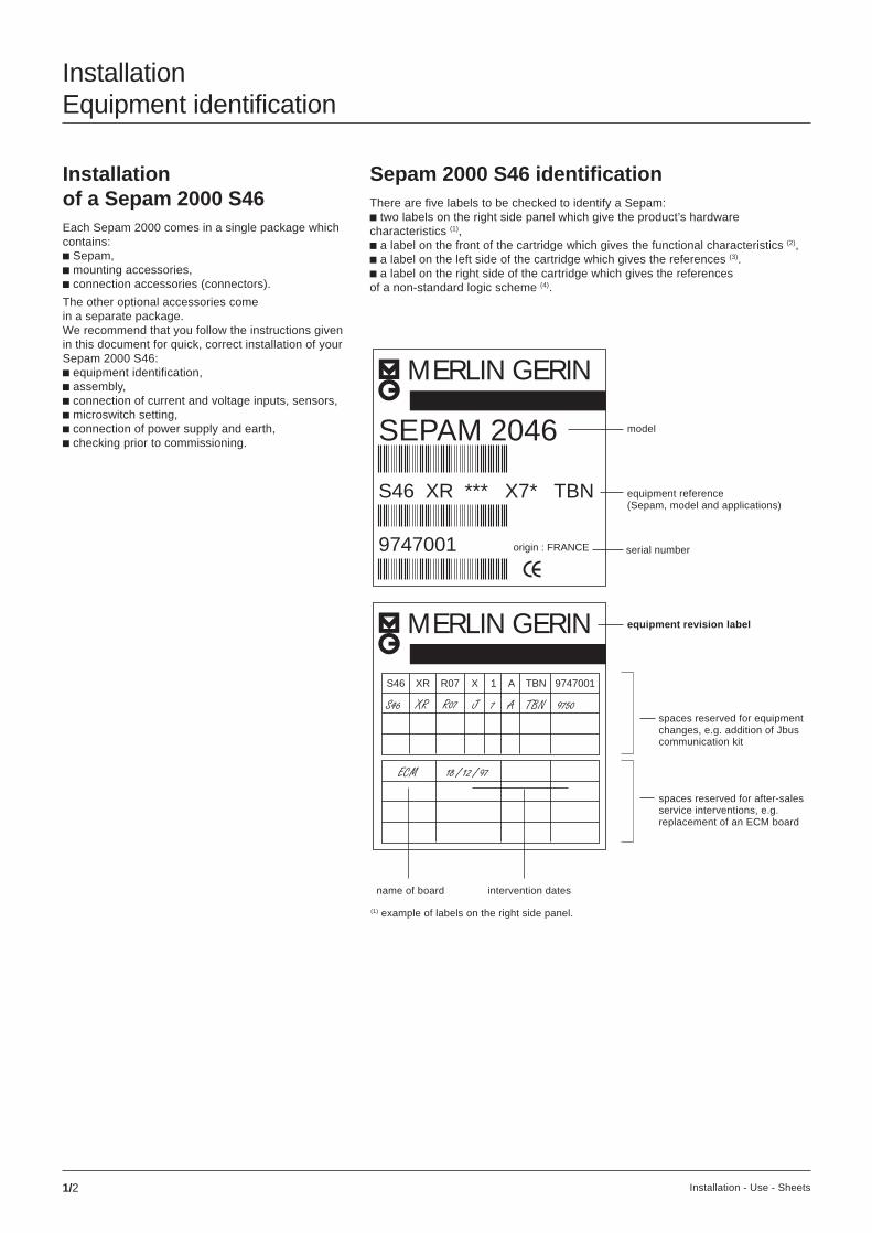
equipment revision label
intervention datesname of board
spaces reserved for after-salesservice interventions, e.g.replacement of an ECM board
spaces reserved for equipmentchanges, e.g. addition of Jbuscommunication kit
equipment reference(Sepam, model and applications)
(1) example of labels on the right side panel.
model
serial number
Sepam 2000 S46 identificationThere are five labels to be checked to identify a Sepam:c two labels on the right side panel which give the product’s hardwarecharacteristics (1),c a label on the front of the cartridge which gives the functional characteristics (2),c a label on the left side of the cartridge which gives the references (3).c a label on the right side of the cartridge which gives the referencesof a non-standard logic scheme (4).
9747001
MERLIN GERIN
S46 XR *** X7* TBN
MERLIN GERIN
origin : FRANCE
SEPAM 2046
S46 XR R07 X 1 A TBN 9747001

1/3Installation - Use - Sheets
Date VersionSepam réf.
Proj réf.
Drwg réf.
Cubicle réf.
(2) example of label on front of cartridge.
(4) lable on right side of cartridge.
identification ofa non-standardlogic scheme
(3) example of label on left side of cartridge.
Each Sepam is identified by a 14-character referencewhich describes its hardware and functionalcomposition in accordance with the chart below.
series model type variants com. total number operating current auxiliary operatingof boards ETOR language sensor supply temperature
S46 RR R = RTU 1 to 99 x = none 3 = 3 F = French x = none N = -5 / +55 °CXR J = Jbus 4 = 4 A = English T = CT B = 48/125 Vdc
NR 5 = 5 I = Italian C = 220 Vdc
ZR 6 = 6 E = Spanish
7 = 7
03143764FA-B0-01-97322211
Sepam model
type of application
control logicdiagram reference
S46: Sepam 2046XR: modelR07: type
8: Sepam S46XR: modelR07: typeA: englishA: rev. level
S46 XR R07
8 XR R07 AA363 RA A

1/4 Installation - Use - Sheets
InstallationEquipment identification (cont’d)
Accessories suppliedwith SepamEach Sepam comes with the following accessories:
CCA 604 connector4-pin. Connection of power supply:c screw terminals,c 0.6 to 2.5 mm2 wire(awg 20 to awg 14).
CCA 608 connector(according to type of Sepam)8-pin. Connection of VTs:c screw terminals,c 0.6 to 2.5 mm2 wire(awg 20 to awg 14).
CCA 660 connector for connectionof 1 A or 5 A CTs:c for 4 mm eye lugs,c for max. 6 mm2 wire (awg 10).
CCA 606 connector(according to type of Sepam)6-pin:c screw terminals,c 0.6 to 2.5 mm2 wire(awg 20 to awg 14).
2 Sepam mounting lugs
CCA 621 connector21-pin. Connection of logic inputs/outputs, temperature sensors andlow level analog inputs:c screw terminals,c 0.6 to 2.5 mm2 wire (awg 20 to awg 14).
1/5Installation - Use - Sheets
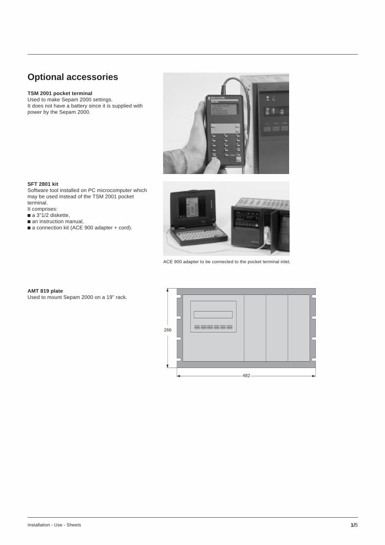
Optional accessories
TSM 2001 pocket terminalUsed to make Sepam 2000 settings.It does not have a battery since it is supplied withpower by the Sepam 2000.
AMT 819 plateUsed to mount Sepam 2000 on a 19" rack.
SFT 2801 kitSoftware tool installed on PC microcomputer whichmay be used instead of the TSM 2001 pocketterminal.It comprises:c a 3"1/2 diskette,c an instruction manual,c a connection kit (ACE 900 adapter + cord).
ACE 900 adapter to be connected to the pocket terminal inlet.
482
266
1/6 Installation - Use - Sheets
InstallationEquipment identification (cont’d)
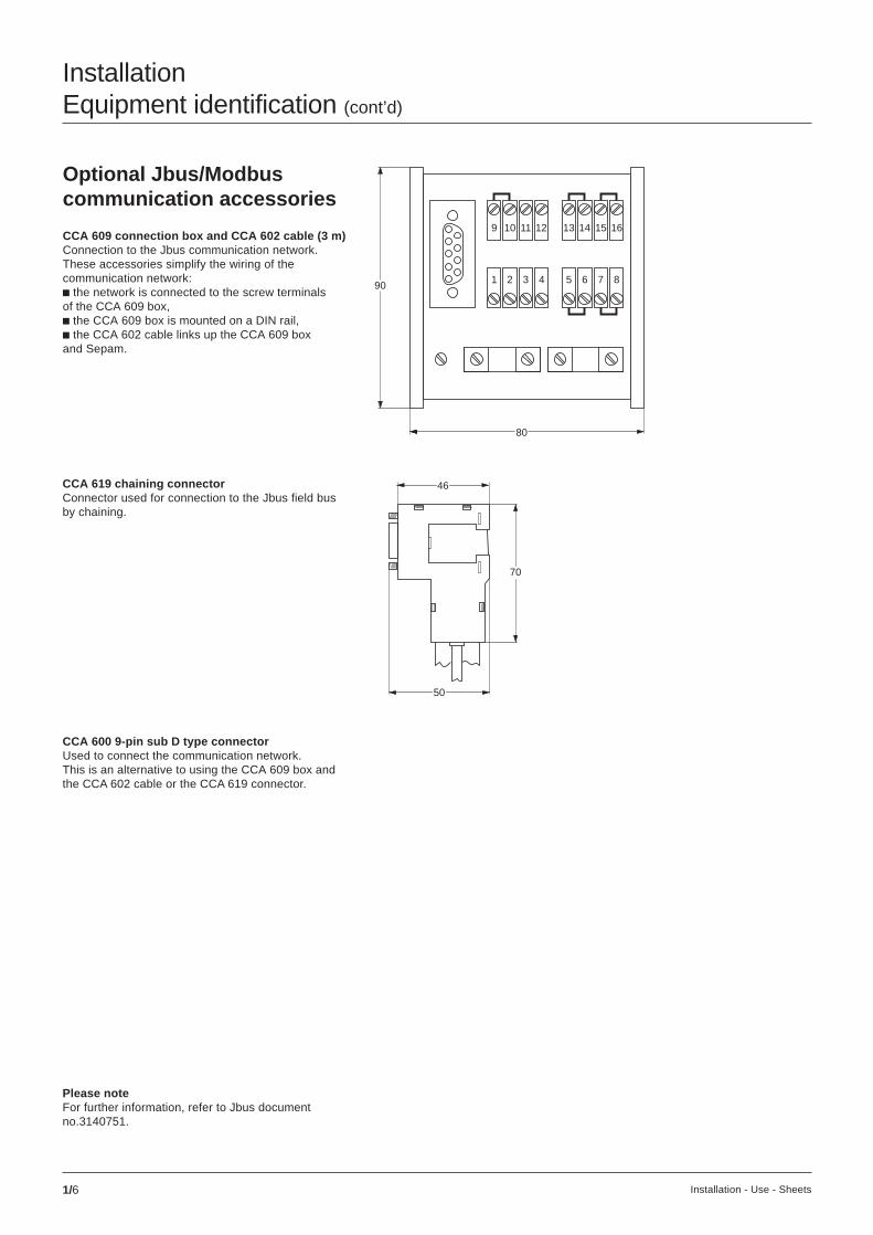
Optional Jbus/Modbuscommunication accessories
CCA 609 connection box and CCA 602 cable (3 m)Connection to the Jbus communication network.These accessories simplify the wiring of thecommunication network:c the network is connected to the screw terminalsof the CCA 609 box,c the CCA 609 box is mounted on a DIN rail,c the CCA 602 cable links up the CCA 609 boxand Sepam.
CCA 619 chaining connectorConnector used for connection to the Jbus field busby chaining.
CCA 600 9-pin sub D type connectorUsed to connect the communication network.This is an alternative to using the CCA 609 box andthe CCA 602 cable or the CCA 619 connector.
Please noteFor further information, refer to Jbus documentno.3140751.
46
70
50
9 10 11 12 13 14 15 16
1 2 3 4 5 6 7 8
80
90
1/7Installation - Use - Sheets
(2)(2)
(1)
InstallationAssembly and wiring
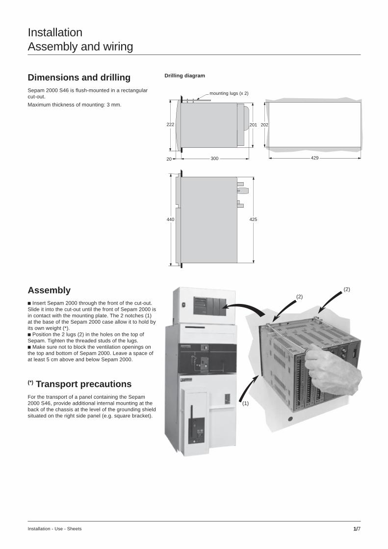
Assemblyc Insert Sepam 2000 through the front of the cut-out.Slide it into the cut-out until the front of Sepam 2000 isin contact with the mounting plate. The 2 notches (1)at the base of the Sepam 2000 case allow it to hold byits own weight (*).c Position the 2 lugs (2) in the holes on the top ofSepam. Tighten the threaded studs of the lugs.c Make sure not to block the ventilation openings onthe top and bottom of Sepam 2000. Leave a space ofat least 5 cm above and below Sepam 2000.
(*) Transport precautionsFor the transport of a panel containing the Sepam2000 S46, provide additional internal mounting at theback of the chassis at the level of the grounding shieldsituated on the right side panel (e.g. square bracket).
Drilling diagramDimensions and drillingSepam 2000 S46 is flush-mounted in a rectangularcut-out.
Maximum thickness of mounting: 3 mm.
440 425
201
20 300
222
mounting lugs (x 2)
429
202
1/8 Installation - Use - Sheets
B
B
123456
A
SW1
SW2
+
B
A
1234
V-D
C24
-30
48-1
2522
0-25
0
123456789101112131415161718192021
123456789101112131415161718192021
STOR STOR STOR SBW 3U/Vo3V+V
CE407 6 5 4 3 2 1
A
123456789101112131415161718192021
SW1
A
12345678
ECM
optional modules
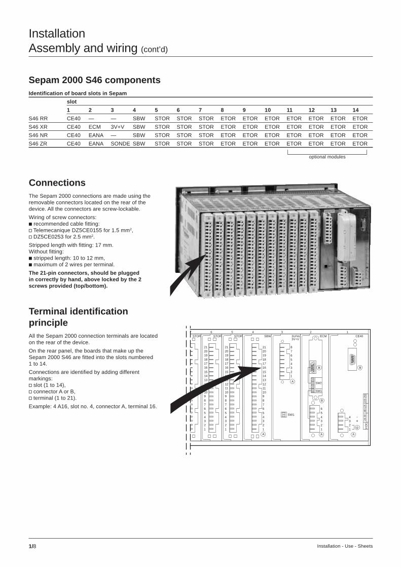
InstallationAssembly and wiring (cont’d)
Sepam 2000 S46 componentsIdentification of board slots in Sepam
slot
1 2 3 4 5 6 7 8 9 10 11 12 13 14
S46 RR CE40 — — SBW STOR STOR STOR ETOR ETOR ETOR ETOR ETOR ETOR ETOR
S46 XR CE40 ECM 3V+V SBW STOR STOR STOR ETOR ETOR ETOR ETOR ETOR ETOR ETOR
S46 NR CE40 EANA — SBW STOR STOR STOR ETOR ETOR ETOR ETOR ETOR ETOR ETOR
S46 ZR CE40 EANA SONDE SBW STOR STOR STOR ETOR ETOR ETOR ETOR ETOR ETOR ETOR
ConnectionsThe Sepam 2000 connections are made using theremovable connectors located on the rear of thedevice. All the connectors are screw-lockable.
Wiring of screw connectors:c recommended cable fitting:v Telemecanique DZ5CE0155 for 1.5 mm2,v DZ5CE0253 for 2.5 mm2.
Stripped length with fitting: 17 mm.Without fitting:c stripped length: 10 to 12 mm,c maximum of 2 wires per terminal.
The 21-pin connectors, should be pluggedin correctly by hand, above locked by the 2screws provided (top/bottom).
Terminal identificationprincipleAll the Sepam 2000 connection terminals are locatedon the rear of the device.
On the rear panel, the boards that make up theSepam 2000 S46 are fitted into the slots numbered1 to 14.
Connections are identified by adding differentmarkings:v slot (1 to 14),v connector A or B,v terminal (1 to 21).
Example: 4 A16, slot no. 4, connector A, terminal 16.

1/9Installation - Use - Sheets
B
B
123456
A
SW1
SW2
+
B
A
1234
V-D
C24
-30
48-1
2522
0-25
0
123456789101112131415161718192021
123456789101112131415161718192021
STOR STOR STOR SBW 3U/Vo3V+V
CE407 6 5 4 3 2 1
A
123456789101112131415161718192021
SW1
A
12345678
ECM
InstallationConnection of current inputs to 1 A or 5 A CTs
For use on 5 Asecondary.
For use on 1 Asecondary.
Selection of operating modes(SW2 microswitches)Sepam 2000 has several possible operating modes.The operating mode is selected via microswitcheson the rear of the device. They must be set beforeSepam 2000 is put into operation. The microswitchesmust be set while Sepam 2000 is de-energized.
The microswitches are hidden by the CCA 660connector once it has been installed.
Concerns Sepam 2000 S46 XR.
The current transformer (1 A or 5 A) secondary circuitsare connected to the CCA 660 connector on the ECMmodule. This connector contains 3 core balance CTprimary crossing adapters, which ensure impedancematching and isolation between the 1 A or 5 A circuitsand Sepam 2000.
This connector may be disconnected with the poweron since disconnection does not open the CTsecondary circuit.
1 A or 5 A CT blockand connection diagram
Microswitch setting
not used(not applicable)
not used(not applicable)
L1
Sepamcurrentinputs
L2
L3
P1
P2
B4B1
B5B2
B6B3
DPC
CCA 660
ECM
1 2 3
SW1
SW2
5 A CT
SW2
1 A CT
SW1

1/10 Installation - Use - Sheets
InstallationConnection of current inputs to 1 A or 5 A CTs (cont’d)
CCA 660 connectorc Open the 2 side shields for access to theconnection terminals. The shields may be removedif necessary to facilitate wiring. If they are removed,put them back after wiring.c Remove the bridging strap if necessary.The strap links terminals 1, 2 and 3.c Connect the cables using 4 mm eye lugs.The connector accommodates cables withcross-sections of 1.5 to 6 mm2 (awg 16 to awg 10).c Close the side shields.
c Tighten the CT connector fastening screwson the rear of Sepam.
c Plug the connector into the 9-pin inlet on the rearof the device. Item B on the ECM module.

1/11Installation - Use - Sheets
B
B
123456
A
SW1
SW2
+
B
A
1234
V-D
C24
-30
48-1
2522
0-25
0
123456789101112131415161718192021
123456789101112131415161718192021
STOR STOR STOR SBW 3U/Vo3V+V
CE407 6 5 4 3 2 1
A
123456789101112131415161718192021
SW1
A
12345678
ECM
InstallationConnection of voltage inputs
Connection of 1 VTs
Connection of 3 VTsThis arrangement allows Sepam to measure the 3phase-to-neutral and phase-to-phase voltages.(Associated with the parameter setting of Number =“V1-V2-V3” in the VT ratio status menu).
Concerns Sepam 2000 S46 XR with voltage inputs.
The voltage transformers (VTs) are connected to the8-pin CCA 608 connectors on the 3V + V module.
The Sepam 2000 S46 can operate with 1 or 3 VTs.
The SW1 microswitches are factory-set.
Any other position can cause incorrect operation.
16
2345
3V+V
L1
L2
L3
78
DPC
3A
P2 P1
S1S2
Connection of a V1 voltagetransformer (*).
Connection of a V2 voltagetransformer (**).
Connection of a V3 voltagetransformer (***).
Connection associated with parameters setting:(*) Number = V1(**) Number = V2(***) Number = V3in the Sepam VT ratio status menu.
16
2345
3V+V
L1
L2
L3
78
DPC
3A
16
2345
3V+V
L1
L2
L3
78
DPC
3A
16
2345
3V+V
L1
L2
L3
78
DPC
3A
1/12 Installation - Use - Sheets
123456789101112131415161718192021
123456789101112131415161718192021
STOR STOR STOR7 6 5
EANA2
SONDE3
SBW4
A
123456789101112131415161718192021
+
B
A
1234
V-D
C24
-30
48-1
2522
0-25
0
CE401
A
123456789101112131415161718192021
A
123456789101112131415161718192021
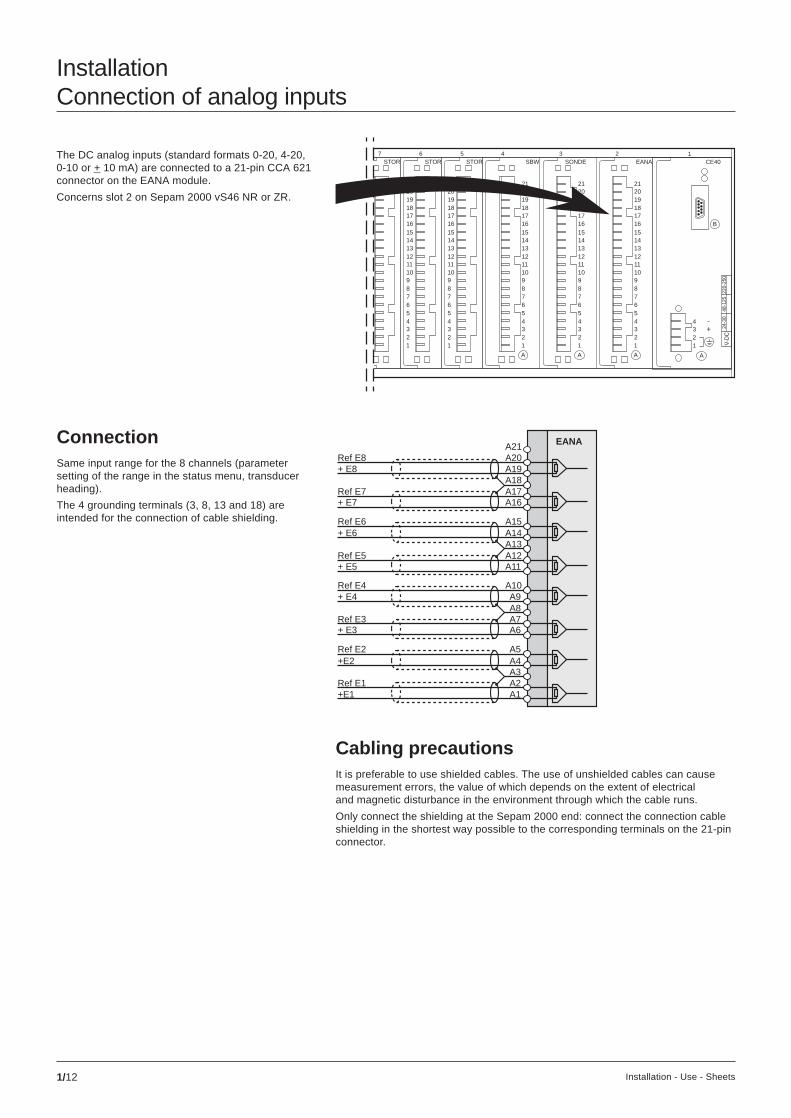
InstallationConnection of analog inputs
The DC analog inputs (standard formats 0-20, 4-20,0-10 or + 10 mA) are connected to a 21-pin CCA 621connector on the EANA module.
Concerns slot 2 on Sepam 2000 vS46 NR or ZR.
ConnectionSame input range for the 8 channels (parametersetting of the range in the status menu, transducerheading).
The 4 grounding terminals (3, 8, 13 and 18) areintended for the connection of cable shielding.
Cabling precautionsIt is preferable to use shielded cables. The use of unshielded cables can causemeasurement errors, the value of which depends on the extent of electricaland magnetic disturbance in the environment through which the cable runs.
Only connect the shielding at the Sepam 2000 end: connect the connection cableshielding in the shortest way possible to the corresponding terminals on the 21-pinconnector.
A21 EANA
Ref E1A1
A3A4
Ref E2
Ref E3A6
A8+ E4Ref E4
Ref E5+ E5
A13+ E6Ref E6
Ref E7A16
A18A19A20Ref E8
+ E8
A17+ E7
A15A14
A12A11
A10A9
A7+ E3
A5+E2
A2+E1

1/13Installation - Use - Sheets
123456789101112131415161718192021
123456789101112131415161718192021
STOR STOR STOR7 6 5
EANA2
SONDE3
SBW4
A
123456789101112131415161718192021
+
B
A
1234
V-D
C24
-30
48-1
2522
0-25
0
CE401
A
123456789101112131415161718192021
A
123456789101112131415161718192021
InstallationConnection of Pt100 temperature sensors
The Pt100 sensors are connected tothe CCA 621 21-pin connector on the SONDEmodule of Sepam 2000 S46 ZR.
2-wire mode3-wire mode
Cabling precautionsIt is preferable to use shielded cables.
The use of unshielded cables can cause measurement errors, the value of whichdepends on the extent of electrical and magnetic disturbance in the environmentthrough which the cable runs.
Only connect the shielding at the Sepam 2000 end: connect the connection cableshielding in the shortest way possible to the corresponding terminals on the 21-pinconnector.
Do not connect the shielding at the temperature sensor end.Recommended cross-sections according to distance:c up to 100 m > 1 mm2, awg 16,c up to 300 m u 1,5 mm2, awg 14,c up to 1 km u 2,5 mm2, awg 12.
N.B. The following wiring must be donewhen one of the measurement channelsis not being used, e.g. channel 6.
Connectionof temperature sensorsUse the 2-wire connection mode only when the 3-wiremode is impossible (e.g. existing cable) since itintroduces a substantial measurement error.
DPC
Pt100n°5
A21A20A19
A17A16
A13A12A11
A5
A10
A14A15
A18
A7A6
A4
A2
A9A8
A3
A1
Pt100n°4
Pt100n°3
Pt100n°2
Pt100n°1
sensors
DPC
Pt100n°5
A21A20A19
A17A16
A13A12A11
A5
A10
A14A15
A18
A7A6
A4
A2
A9A8
A3
A1
Pt100n°4
Pt100n°3
Pt100n°2
Pt100n°1
sensors
A17
A16
A18
1/14 Installation - Use - Sheets
B
B
123456
A
SW1
SW2
+
B
A
1234
V-D
C24
-30
48-1
2522
0-25
0
123456789101112131415161718192021
123456789101112131415161718192021
STOR STOR STOR SBW 3U/Vo3V+V
CE407 6 5 4 3 2 1
A
123456789101112131415161718192021
SW1
A
12345678
ECM
B
B
123456
A
SW1
SW2
+
B
A
1234
V-D
C24
-30
48-1
2522
0-25
0
123456789101112131415161718192021
123456789101112131415161718192021
STOR STOR STOR SBW 3U/Vo3V+V
CE407 6 5 4 3 2 1
A
123456789101112131415161718192021
SW1
A
12345678
ECM
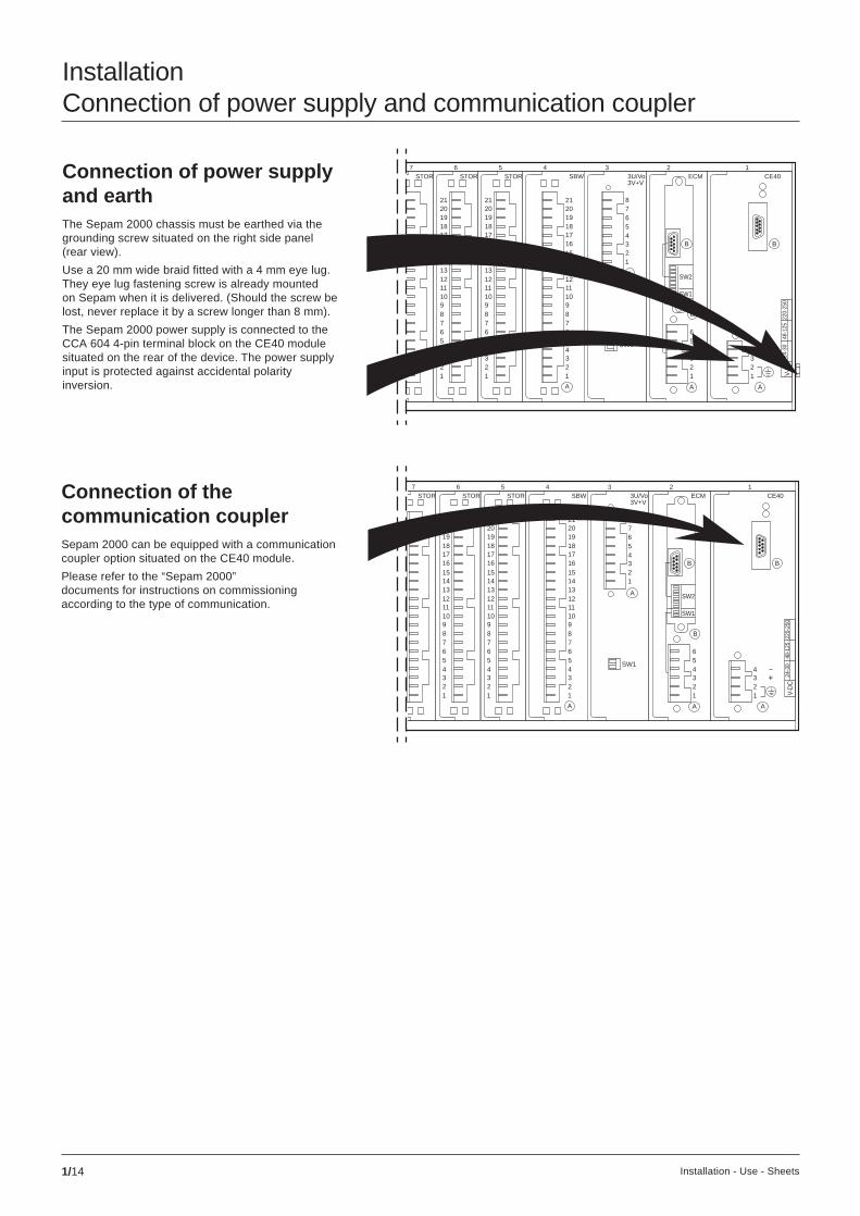
InstallationConnection of power supply and communication coupler
Connection of power supplyand earthThe Sepam 2000 chassis must be earthed via thegrounding screw situated on the right side panel(rear view).
Use a 20 mm wide braid fitted with a 4 mm eye lug.They eye lug fastening screw is already mountedon Sepam when it is delivered. (Should the screw belost, never replace it by a screw longer than 8 mm).
The Sepam 2000 power supply is connected to theCCA 604 4-pin terminal block on the CE40 modulesituated on the rear of the device. The power supplyinput is protected against accidental polarityinversion.
Connection of thecommunication couplerSepam 2000 can be equipped with a communicationcoupler option situated on the CE40 module.
Please refer to the “Sepam 2000”documents for instructions on commissioningaccording to the type of communication.

1/15Installation - Use - Sheets
B
B
123456
A
SW1
SW2
+
B
A
1234
V-D
C24
-30
48-1
2522
0-25
0
ETOR
123456789101112131415161718192021
123456789101112131415161718192021
123456789101112131415161718192021
123456789101112131415161718192021
123456789101112131415161718192021
123456789101112131415161718192021
123456789101112131415161718192021
123456789101112131415161718192021
123456789101112131415161718192021
123456789101112131415161718192021
ETOR ETOR ETOR ETOR ETOR ETOR STOR STOR STOR SBW 3U/Vo3V+V
CE4014 13 12 11 10 9 8 7 6 5 4 3 2 1
A
123456789101112131415161718192021
SW1
A
12345678
ECM
InstallationConnection of logic inputs and outputs
The logic information is connected to the CCA 621 connector on the followingmodules:c SBW (slot 4),c STOR (slots 5 to 7),c ETOR (slots 8 to 10 as standard, and 11 to 14 according to options).
The A21 terminals (DPC) on the SBW, STOR and ETOR modules do not requireany wiring.
x = ETOR board number,from 1 (slot 8) to 7 (slot 14).
x = STOR board number,from 1 (slot 5) to 3 (slot 7).
logic inputs logic outputs
Connection Outputs
Check that the voltageapplied to the inputsis compatible with thevoltage indicated by a pointon the subassembly.
Inputs
Ix01
ETOR
Ix02Ix03Ix04
Ix05Ix06Ix07Ix08
Ix09Ix10Ix11Ix12
Ix13Ix14Ix15Ix16
DPCA21A20A19
A17A16
A13A12A11
A5
A10
A14A15
A18
A7A6
A4
A2
A9A8
A3
A1
O003
O002
O001
O004
O005
O006
O007
O008
CDG
SBWA21A20A19
A17A16
A13A12A11
A5
A10
A14A15
A18
A7A6
A4
A2
A9A8
A3
A1
DPC
Ox03
Ox02
Ox01
Ox04
Ox05
Ox06
Ox07
Ox08
Ox10
STOR
Ox09
DPCA21A20A19
A17A16
A13A12A11
A5
A10
A14A15
A18
A7A6
A4
A2
A9A8
A3
A1

1/16 Installation - Use - Sheets
Notes

2/1Installation - Use - Sheets
Use - commissioningContents
chapter / page
use - commissioning 2/ 1
description / use 2/ 2front panel 2/2TSM 2001 pocket terminal 2/4
use (current operation) 2/ 6energizing 2/6operation via front panel or TSM 2001 pocket terminal 2/6operation via TSM 2001 pocket terminal only 2/7clearing measurements 2/7annunciation 2/7
commissioning 2/ 8checking prior to commissioning 2/8commissioning using TSM 2001 pocket terminal 2/9control logic and annunciation 2/10control logic resource chart 2/10
maintenance 2/ 11display indicators and messages 2/11tests 2/12Sepam replacement 2/12Sepam identification using TSM 2001 pocket terminal 2/13
access password 2/ 15use of access password 2/15
setting record sheets 3/ 1

2/2 Installation - Use - Sheets
Use - commissioningDescription / use
Your Sepam 2000 S46 is a digital unit which performsthe switchgear control and monitoring functionsnecessary for operation:c masurements via current and voltage transformers,and existing measurement converters,c indication of switchgear status via logic inputs,c control of devices via relay outputs,c remote monitoring and remote controlvia a computer.
Sepam 2000 may be equipped (as an option)with a communication link with the telecontrol station.There is a single standard Sepam S46 model.
Standard model: Sepam 2000 S46.
1 status indicators2 display3 keys for access to measurements and alarms4 cartridge5 pocket terminal socket
Status indicators 1 :c green on lamp shows that Sepam 2000 is energized,c red lamp indicates internal Sepam faults.
All the output relays are dropped out (fail-safe position).Refer to the chapter on maintenance,c yellow LS1, green LS2, red LS3 indications according to control logicprogramming (e.g. grouping of alarms).
I on tripon O off
A V/Hz W/ϕ Wh clear alarm reset
5
4
3
2
1
MERLIN GERIN
S35XRS05
3XRS05FA
101SFB
Front panel

2/3Installation - Use - Sheets
keys
display
statusindicators 1
2
3
A/V
on LS1
meter monitoring
CB resetW/Wh GIS clear alarm
LS2 LS3
Display 2The display unit indicates:c measurements,c operating messages,c switchgear monitoring data.
Keys for access to measurements 3ccccc Metering keyThe measurements may be accessed by pressingthe A/V and W/Wh keys.
Each key provides access to a set of measurementsaccording to the ring method. The followingmeasurement may be accessed by pressing this key.
When a measurement is not available in a typeof Sepam, “- - - - - - - - - - -” is displayed,c Clear keyThis key erases the stored value being displayed(reset):v max. current demand IM1, IM2, IM3,v peak demand power PM, QM,
Keys for access to switchgear monitoringdata 3 :
c CB key: disabled,
Access, according to the ring method, to thecumulative number of breaks of circuit breaker polesas well as the number of starts of the correspondingpumps or compressors.
c GIS key: disabled.
Access to 8 counters of the cumulative numberof switch operations.
Cartridge 4The cartridge contains the information required for Sepam operation,such as:c settings,c stored data,c control and monitoring logic…
Pocket terminal socket 5This socket is used to connect the TSM 2001 pocket terminal or the ACE 900adapter to the SFT 2801 bit (PC link).
Display unit and indicator testWhen the A/V and W/Wh measurement keys are pressed at the same time,all the indicator lamps on the front panel light up as well as the display unit whichindicates *********** and 00000000000 alternatively.
Example: current/voltage measurement.
Keys for access to alarm processing 3 :c Alarm key: each time tripping or another event occurs, an alarm messagestored in a list of alarms is displayed. The most recent message appearson the display unit.
This key provides access to step by step reading of the list of stored alarmmessages. The previous message may be displayed by pressing this key.
Display of: “- - - - - - - - - - -” indicates the end of the list of alarm messages.
c Reset keyAssociated with the K 828 contact (LOGIPAM), this key is used to acknowledgealarms and indications generated by the monitoring functions.
I1
I2
I3
IM2
IM3
U21
U13
F
A/V key
U32
V1
V2
V3
IM1

2/4 Installation - Use - Sheets
TSM 2001 pocket terminalYour pocket terminal provides you with access to allthe Sepam 2000 functions, such as:c current measurements,c operating assistance messages,c parameter settings.
Use - commissioningDescription / use (cont’d)
The pocket terminal is supplied with power by Sepamand does not require any batteries; it can beconnected with the power on. The pocket terminalbeeps when it is connected.
The start-up menu appears (if nothing is displayed,check the brightness adjustment using the dial 3 ).
The user may access the various data from threemenu levels. A menu may comprise several pages.
To access a menu, simply position the blinking cursoron the desired line and press the enter key.
The first line of the menu contains the nameof the current menu or function.
When P/ appears at the head of the menu, it meansthat the user has entered the password.
1 4-line display.
2 data entry keypad.
3 brightness adjustment dial.
Role of keys:c the pocket terminal beeps when the user presses a key that is disabled,c the menu key is used to display the previous menu,c the and keys are used to move the c cursor one line up or downin a menu.
To move to the next screen of a menu, the user simply positions the cursoron the last line and presses the key.
To move to the previous screen of a menu, the user simply positions the cursoron the second line and presses the key,c the code key is used to enter and exit the parameter setting mode,c the number and . keys are used to enter settings and the password,c the units key is used to change the setting unit multiplying factor (e.g. A, kA, …),c the data+ and data- keys are used to select values from preset data tables.The tables are used when only a limited number of values may be usedfor a parameter, e.g. frequency value.c the clear key is used:v to clear error messages,v to call back a previous setting value during data input,v to reset tripping currents and peak demand readings to zero,c the enter key is used to confirm a menu selection or to confirm all the settingsfor a function.
N.B. The first line always contains the name of the current menu or function.
MERLIN GERIN
TSM 2001
menu
7
4
1
8
5
2
.0
clear-
code
9
6
3
units
+
data
enter
S e l e c t
M e t e r i n g
P r o t e c t i o n
P r o g r a m l o g i c
3
2
1
P/Select:
Metering
Protection
Program logic
P/Select:
Add. reading
Status
About Sepam

2/5Installation - Use - Sheets
Enter
Menu
Enter
Menu
Enter
Menu
Enter
Menu
Menu Menu Menu Menu
Menu
Enter
Enter
Menu
Menu
Enter
I PHASE I1 = 453 A I2 = 452 A I3 = 453 A
P/Select: Metering Protection Program logic
P/Select: Status About Sepam
P/sensor 2 F462Ts1 = 50 degTs2 = 100 deg
P/LOGIC INPUT I101-108=0000 0000 I109-116=0000 0000 …
P/PROGRAM LOGIC Logic input Relay output Timer
P/STATUS Rated frequency Phase CT ratio Max demand interv.
P/PROGRAM LOGIC 363RAA LDR CAT TESTING PROGRAM
P/ABOUT SEPAM SFT 2800 Program logic Communication
= 500 A= 500 A= I1-I2-I3
P/PHASE CT RATIO In Ib Number
P/METERING I Phase Max demand current system voltage
P/PROTECTION sensor 1 F461 sensor 2 F462 sensor 3 F463
MERLIN GERIN
TSM 2001
menu
7
4
1
8
5
2
.0
clear-
code
9
6
3
units
+
data
enter
S e l e c t
M e t e r i n g
P r o t e c t i o n
P r o g r a m l o g i c
2/6 Installation - Use - Sheets
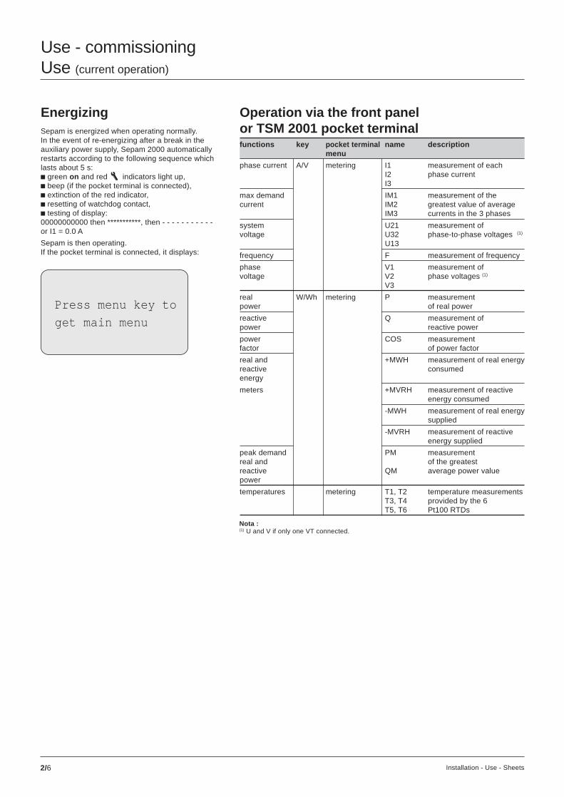
Use - commissioningUse (current operation)
EnergizingSepam is energized when operating normally.In the event of re-energizing after a break in theauxiliary power supply, Sepam 2000 automaticallyrestarts according to the following sequence whichlasts about 5 s:c green on and red indicators light up,c beep (if the pocket terminal is connected),c extinction of the red indicator,c resetting of watchdog contact,c testing of display:00000000000 then ***********, then - - - - - - - - - - -or I1 = 0.0 A
Sepam is then operating.If the pocket terminal is connected, it displays:
functions key pocket terminal name descriptionmenu
phase current A/V metering I1 measurement of eachI2 phase currentI3
max demand IM1 measurement of thecurrent IM2 greatest value of average
IM3 currents in the 3 phases
system U21 measurement ofvoltage U32 phase-to-phase voltages (1)
U13
frequency F measurement of frequency
phase V1 measurement ofvoltage V2 phase voltages (1)
V3
real W/Wh metering P measurementpower of real power
reactive Q measurement ofpower reactive power
power COS measurementfactor of power factor
real and +MWH measurement of real energyreactive consumedenergy
meters +MVRH measurement of reactiveenergy consumed
-MWH measurement of real energysupplied
-MVRH measurement of reactiveenergy supplied
peak demand PM measurementreal and of the greatestreactive QM average power valuepower
temperatures metering T1, T2 temperature measurementsT3, T4 provided by the 6T5, T6 Pt100 RTDs
Operation via the front panelor TSM 2001 pocket terminal
Nota :(1) U and V if only one VT connected.
Press menu key to
get main menu

2/7Installation - Use - Sheets
Operation via the TSM 2001pocket terminal only
functions pocket terminal name descriptionmenu
analog add. Eana1, Eana2 measurement of the DCinputs reading Eana3, Eana4 current of each
Eana5, Eana6 input (values convertedEana7, Eana8 into points)
Mesures accessibles sur l’afficheur de Sepamet sur la console TSM 2001.
AnnunciationWhen an event is detected by Sepam, an operating message appearson the display. The messages are stored in a list of alarms and may be reviewedin chronological order of appearance, starting with the most recent, by pressingthe alarm key.
Please note: Pressing the reset key may erase the contents of the entirelist of alarms (according to the programming done in the customizedcontrol logic).
Clearing measurementsc max demand phase currents.To reset to zero:v press clear on the TSM 2001 pocket terminalif max demand currents are displayed,v press clear on the display if at least onemax demand is displayed,c peak demand real and reactive power.To reset to zero:v press clear on the TSM 2001 pocket terminalif peak demands are displayed,v press clear on the display if at least one peakdemand power is displayed.
N.B. Clearing of the max demands allows calculationsto be started for a new integration interval.
designation type message
customized control logic messages. C M01 to M64Refer to the documents providedby your installer
unplugged connector M CONNECTOR
cartridge and Sepam not compatible M CARTRIDGE
internal Sepam fault M MAINTENANCE
internal cartridge fault M M.CARTRIDGE
C = control and monitoring.M = maintenance.
List of messages

2/8 Installation - Use - Sheets
Checking priorto commissioningThese operation must be carried out beforeSepam 2000 S46 is energized.
Checksc Supply voltage.Ensure that the auxiliary supply voltage matchesSepam 2000’s operating voltage. It is indicatedon the rear of the device, beside the power supplyconnector, by a dot in the voltage box. The supplyvoltage is also marked on the ETOR logic inputboards.
Use - commissioningCommissioning
v the cartridge has an identification label on the front. The last 3 charactersin the first line of the label indicate the type of Sepam 2000 (the type correspondsto the functions performed). Ensure that the type matches the Sepam modelindicated on the side of Sepam.
ExampleS46 XR on the cartridge label should match S46 XR on the Sepam label.
c ConnectorCheck that the connectors are correctly connected to the rear of the deviceand screwed on.
Setting of microswitches on rearCheck that the microswitches which define operating modes and Sepamcalibration operations were correctly set at the time of installation (1).
The microswitches must be set with Sepam de-energizedIf the microswitches are incorrectly set, the measurements given by Sepam 2000will be false.
Default parameter settingFactory-set parameter status:c microswitches:v they are set for supply by a 5 A secondary current transformer,c protection and monitoring:v set points inhibited,v control logic time delay: t = 200 ms.
c Earthing.Check that the Sepam 2000 chassis is earthedby the ground nut situation on the Sepam side panel,on the power supply side.c Cartridge.v Check that the cartridge is in its slot behind the frontwicket door. To do so, open the wicket door by pullingon the notch situation on the left side panel.The Sepam S46 has 2 shields on the right whichresemble the memory cartridge wicket door. Theseshields are not wicket doors and the user should nottry to open them. Check that the cartridge is fullyinserted. Check the tightening of the 2 threadedscrews by hand.
Above all, do not insert or removethe cartridge while Sepam 2000is energized.
(1) see “installation, connection of current and voltage inputs” chapter.
+
A
1234
V-D
C24
-30
48-1
2522
0-25
0
SEPAM 2046S46 XR X7 TBN*** *
S46 XR R07
8XRR07AA363RAA

2/9Installation - Use - Sheets
heading name function command selection
rated Fn network frequency data + and - 50 or 60 Hzfrequency
phase CT In CT rating number adjustable fromratio (standard values) keys 10 A to 6250 A
Ib basis current number Ib set to thekeys value of In
number number of data + and - 2 or 3 sensorscurrent sensors
max demand interval peak demand data + and - adjustable: 5, 10,interval integration times 15, 30, 60 mn
VT ratio number number of wired VTs data + and - V1, V2, V3V1 - V2 - V3
Unp rated VT number adjustable fromprimary voltage keys 220 V to 500 kV
Uns rated VT data + and - 100, 110, 115,secondary voltage 120 V
power flow incomer reverses the signs data + and - incomersense feeder of power and energy feeder
measurements
transducer range EANA board data + and - 0-20 mAinput range 0-10 mA
4-20 mA-10/+10 mA
communi- speed transmission speed data + and - 300, 600, 1200,cation (2) 2400, 4800,
9600, 19200,38400 bds
adress Sepam station number 1 to 255number in the network keys
parity transmission format data + and - even, odd,no parity
time synchro type of synchronization data + and - via networktagging (2) used via inputs
I413 or I501
events (3) KTS 1-8 numberto KTS 57-64 keys
I101-108to I709-716
password see lastpage
Status menu parameter chart
All the parameters and settings are accessible in 3 menus (6) :c general parameters: status menu,c protection: protection menu,c operating parameters: program logic menu.
General parametersThe general parameters are accessible in the status menu. They are to be setat the time of commissioning and must not be modified during current operation.
Example: temperature sensor.
The user should then check and, if necessary, changethe protection settings.
The PROTECTION line blinks until the settings havebeen corrected.
Settings out of range.A protection or monitoring value may be out of rangewhen it is set.
Sepam detects this and indicates the permissiblerange of settings.
(2) please refer to the document “Jbus communication” ref. 3140751 regarding commissioningof the communication link.(3) 8 lines for KTSs, 14 lines for ETOR 1 inputs = time-tagged, 0 = not time-tagged,by default all the events are set to zero.
Commissioning usingTSM 2001 pocket terminal
Switch on the SepamAfter the Sepam starts up, check that thereare no messages on the display unit by pressingthe “alarm” key.
Checking modeAll information may be accessed for checkingpurposes without the risk of changing parametersand settings.
Parameter setting modeThis mode is reserved for commissioningand maintenance. The entry of a password isrequired. P\ appears at the top left of the screen (1).
Parameter and setting errorsChanging a status parameter may put a protectionsetting outside the tolerance range.
Sepam detects this problem and displays thefollowing message:
(1) this mode is automatically removed if no keys are activatedfor about 1 mn, or manually by pressing the Code key.
P\VT ratio
protection settings
out of range
press clear
P\Sensor2 F462
TS1 out of range
0 deg < TS1 < 180 deg
Press Clear
2/10 Installation - Use - Sheets
Use - commissioningCommissioning (cont’d)
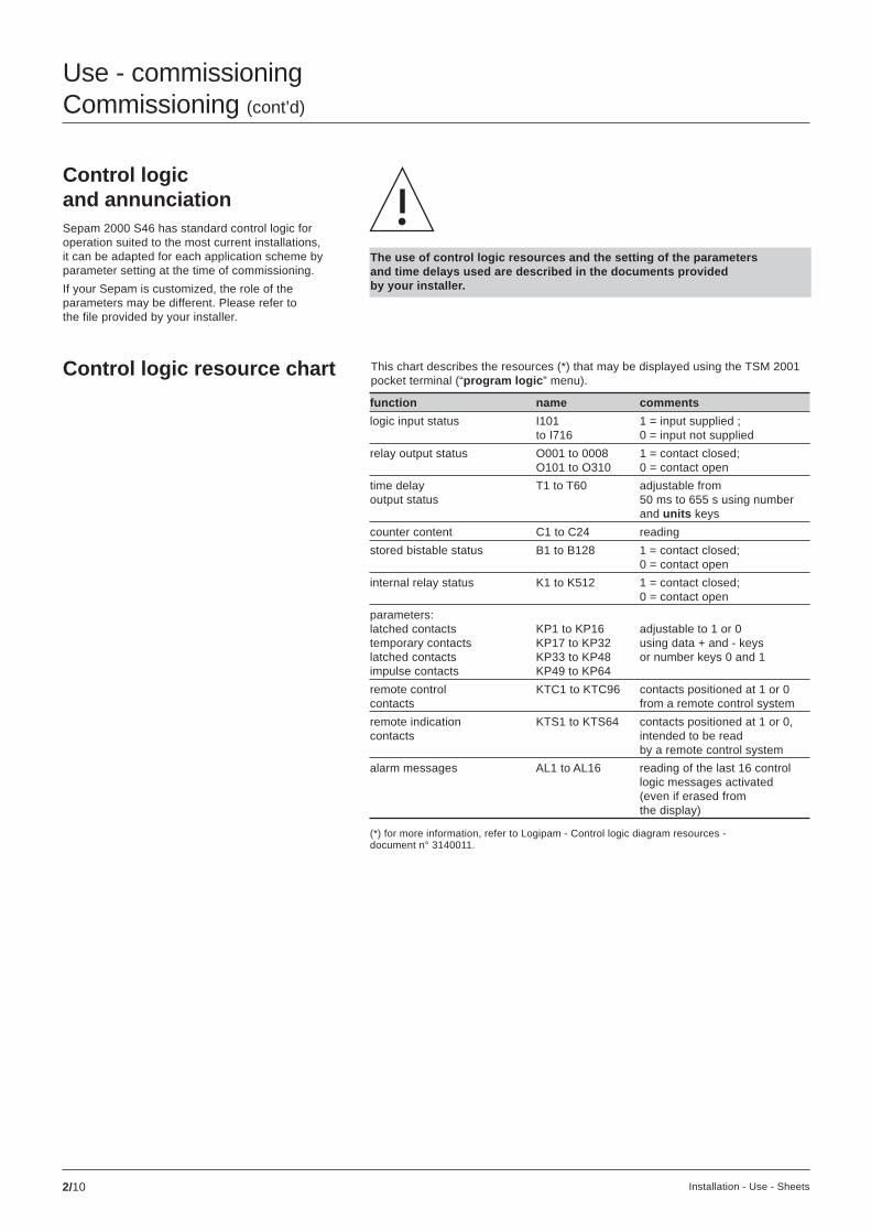
Control logicand annunciationSepam 2000 S46 has standard control logic foroperation suited to the most current installations,it can be adapted for each application scheme byparameter setting at the time of commissioning.
If your Sepam is customized, the role of theparameters may be different. Please refer tothe file provided by your installer.
function name comments
logic input status I101 1 = input supplied ;to I716 0 = input not supplied
relay output status O001 to 0008 1 = contact closed;O101 to O310 0 = contact open
time delay T1 to T60 adjustable fromoutput status 50 ms to 655 s using number
and units keys
counter content C1 to C24 reading
stored bistable status B1 to B128 1 = contact closed;0 = contact open
internal relay status K1 to K512 1 = contact closed;0 = contact open
parameters:latched contacts KP1 to KP16 adjustable to 1 or 0temporary contacts KP17 to KP32 using data + and - keyslatched contacts KP33 to KP48 or number keys 0 and 1impulse contacts KP49 to KP64
remote control KTC1 to KTC96 contacts positioned at 1 or 0contacts from a remote control system
remote indication KTS1 to KTS64 contacts positioned at 1 or 0,contacts intended to be read
by a remote control system
alarm messages AL1 to AL16 reading of the last 16 controllogic messages activated(even if erased fromthe display)
(*) for more information, refer to Logipam - Control logic diagram resources -document n° 3140011.
Control logic resource chart This chart describes the resources (*) that may be displayed using the TSM 2001pocket terminal (“program logic ” menu).
The use of control logic resources and the setting of the parametersand time delays used are described in the documents providedby your installer.
2/11Installation - Use - Sheets
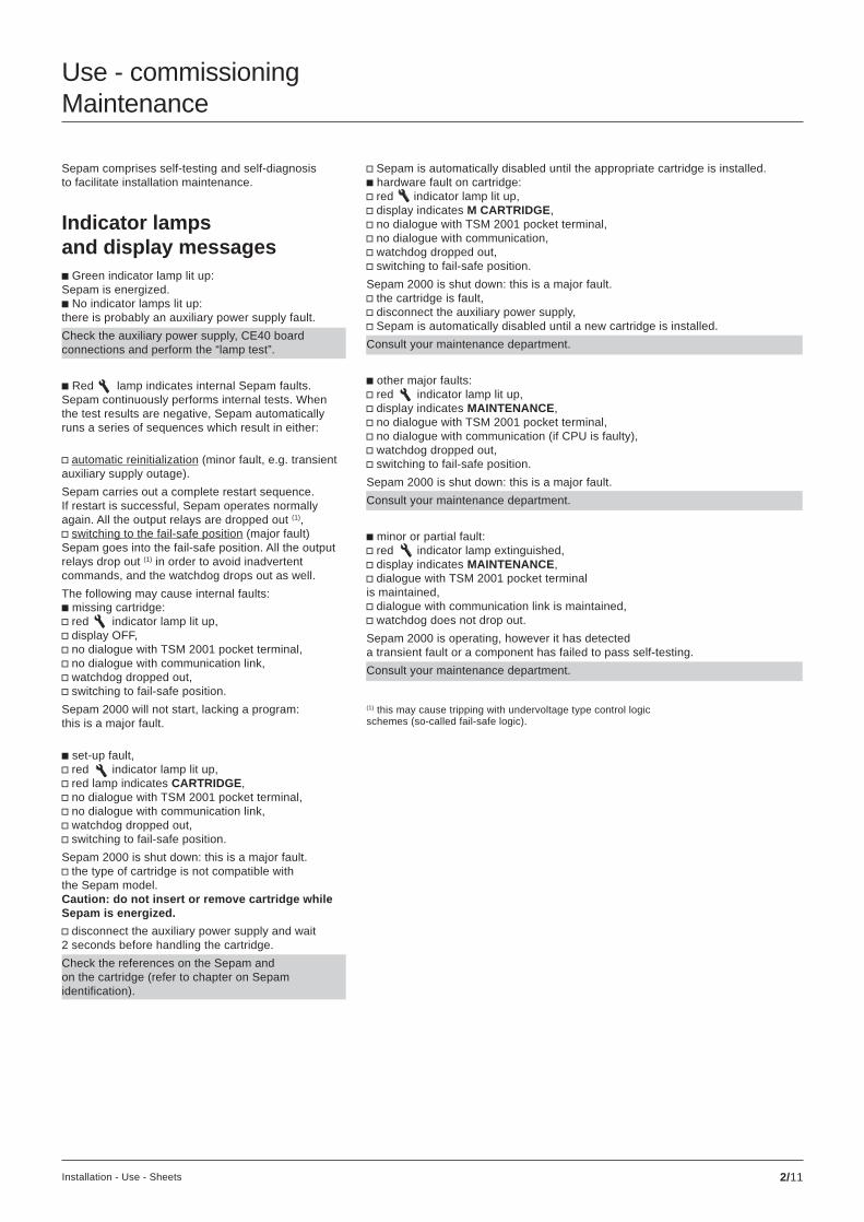
Sepam comprises self-testing and self-diagnosisto facilitate installation maintenance.
Indicator lampsand display messagesc Green indicator lamp lit up:Sepam is energized.c No indicator lamps lit up:there is probably an auxiliary power supply fault.
Check the auxiliary power supply, CE40 boardconnections and perform the “lamp test”.
c Red lamp indicates internal Sepam faults.Sepam continuously performs internal tests. Whenthe test results are negative, Sepam automaticallyruns a series of sequences which result in either:
v automatic reinitialization (minor fault, e.g. transientauxiliary supply outage).
Sepam carries out a complete restart sequence.If restart is successful, Sepam operates normallyagain. All the output relays are dropped out (1),v switching to the fail-safe position (major fault)Sepam goes into the fail-safe position. All the outputrelays drop out (1) in order to avoid inadvertentcommands, and the watchdog drops out as well.
The following may cause internal faults:c missing cartridge:v red indicator lamp lit up,v display OFF,v no dialogue with TSM 2001 pocket terminal,v no dialogue with communication link,v watchdog dropped out,v switching to fail-safe position.
Sepam 2000 will not start, lacking a program:this is a major fault.
c set-up fault,v red indicator lamp lit up,v red lamp indicates CARTRIDGE,v no dialogue with TSM 2001 pocket terminal,v no dialogue with communication link,v watchdog dropped out,v switching to fail-safe position.
Sepam 2000 is shut down: this is a major fault.v the type of cartridge is not compatible withthe Sepam model.Caution: do not insert or remove cartridge whileSepam is energized.
v disconnect the auxiliary power supply and wait2 seconds before handling the cartridge.
Check the references on the Sepam andon the cartridge (refer to chapter on Sepamidentification).
v Sepam is automatically disabled until the appropriate cartridge is installed.c hardware fault on cartridge:v red indicator lamp lit up,v display indicates M CARTRIDGE,v no dialogue with TSM 2001 pocket terminal,v no dialogue with communication,v watchdog dropped out,v switching to fail-safe position.
Sepam 2000 is shut down: this is a major fault.v the cartridge is fault,v disconnect the auxiliary power supply,v Sepam is automatically disabled until a new cartridge is installed.
Consult your maintenance department.
c other major faults:v red indicator lamp lit up,v display indicates MAINTENANCE ,v no dialogue with TSM 2001 pocket terminal,v no dialogue with communication (if CPU is faulty),v watchdog dropped out,v switching to fail-safe position.
Sepam 2000 is shut down: this is a major fault.
Consult your maintenance department.
c minor or partial fault:v red indicator lamp extinguished,v display indicates MAINTENANCE ,v dialogue with TSM 2001 pocket terminalis maintained,v dialogue with communication link is maintained,v watchdog does not drop out.
Sepam 2000 is operating, however it has detecteda transient fault or a component has failed to pass self-testing.
Consult your maintenance department.
(1) this may cause tripping with undervoltage type control logicschemes (so-called fail-safe logic).
Use - commissioningMaintenance

2/12 Installation - Use - Sheets
c CONNECTORv indication that on e or more connectors areunplugged (according to customized control logic).
Check that the connectors are plugged in andtightened by the screws on the rear of the device.
Check that the DPC has been strappedto the connectors on the ECM, 3V+Vand SONDE boards.
Lamp testWhen the user presses the A/V and W/Wh measurement keys simultaneously,all the indicators on the front of the device light up, as well as the display whichindicates *********** and 00000000000 alternatively..
Sepam replacementWhen Sepam is replaced:c switch off Sepam,c dismantle the Sepam to be replaced,c remove the cartridge,c mount the Sepam replacement (hardware set-up),c install the cartridge,c check the compatibility of the cartridge and Sepam(see chapter on identification),c set microswitches SW2 on the rear of the device in the same positionsas they were in on the Sepam that was replaced,c install the connectors, checking their markings,c energize Sepam.
Communication indicator lamps
These lamps are located at the rear of the deviceon the CE40 module when the module is equippedwith the communication option.c Green indicator lamp blinking: indicates trafficon the line. This is the normal operating mode.c Indicator lamps extinguished: there is no communication.
Check network cabling and inquiriesat the level above.
c Red indicator lamp lit up: indicates initializationof the coupler, which lasts about 2 seconds, or acoupler fault.
Consult your maintenance department.
c Red indicator lamp lit up and therecommendations given in the maintenance chapterdo not allow Sepam to be restarted.
Call in the maintenance department.
Use - commissioningMaintenance (cont’d)

2/13Installation - Use - Sheets
Sepam identification using the TSM 2001pocket terminal
Menu: About Sepam
ReminderIn the event of a cartridge error or incompatibility with Sepam, the CARTRIDGE messageappears on the front of Sepam. Check consistency between the cartridge and Sepam.
ABOUT SEPAM SFT2800 Program logic Communication
SFT2800 8XRR07FA CAT SFT2800 97.45
Enter
ABOUT SEPAM SFT2800 Program logic Communication
PROGRAM LOGIC 363RFA APPLICATION RTU
Enter
PROGRAM LOGIC program date: 97/12/01 15:08 LOGIPAM : 97.45
application type
8 = Sepam S46XR = modelR07 = typeF = FrenchA = rev. level.
configuratorversion no.
CAT = standard configuration
control logicdiagram reference
name of control diagramproduced by LOGIPAM
control logic diagramprogramming date
configurator version
Communication J bus : V 3.0
Jbus communication version 3.0- Communication not installed press menu key

2/14 Installation - Use - Sheets

2/15Installation - Use - Sheets
Loss of the passwordIf the original password has been modified and the latest password entered hasbeen permanently lost by the user, the only means of regaining access tomodification of parameters and settings is to reprogram the cartridge using a PCequipped with the LOGIPAM software package, the PER2901 programmer andthe Sepam program logic “source” file (regarding the “source” file, see the sectionon Sepam identification using the TSM 2001 pocket terminal).
N.B. Before reprogramming the cartridge, it is advisable to make a complete record ofthe values set in the Sepam as well as the identification information. This operation may becarried out using the TSM 2001 pocket terminal or the SFT 2801 software package.
Use of the passwordThe user enters a password via the TSM 2001 pocketterminal in order to able to change parametersand settings.
Code keyWhen the user presses the code key, the followingmenu appears:
N.B. If you do not want your operating personnel to know thepassword that gives access to the parameter setting mode,remove this page from the user’s documentation.
(1) code by default in standard control logic; withcustomization, the password is given by the installer.(2) 7 figures are mandatory.
Use - commissioningPassword
Modification of the passwordc go to parameter setting mode,c in the Status menu, choose the password heading using the arrow and pressenter .
The following window is displayed:
Type 6543210 (1) on the keypad and then press enter
This is the password for standard Sepams.If your Sepam has been customized, referto the documentation provided by your installer.
To exist this mode, simply:c press the code key,c wait 2 min after activating any key.
When the pocket terminal is in parameter settingmode, P\ appears on the top left of the screen.
c enter, one after the other:v the password to be modified in the “old” line, (2)
v the new password in the “new” and “verif” lines, (2)
v after each password, press enter to go to the next line.c at the end of the sequence, the following window is displayed:
c press enter : the new password is validated.
Please note:If the passwords entered for “new” and “verif” are different, the following messageis displayed:
Enter your password
then press enter key
PASSWORD
old =
new =
verif =
P/PASSWORD
Validate settings
Yes = Enter No = Clear
P/PASSWORD
new password
not valid
press clear

2/16 Installation - Use - Sheets
Notes

3/1Installation - Use - Sheets
SETTING RECORD SHEET Sepam 2000 S46Project: .....................................................................................................
.......................................................................................................................
.......................................................................................................................
.......................................................................................................................
Type
serial no.
G
Status menu parametersmenu name function
frequency Fn network frequency 50 Hz 60 Hz
Phase CT In CT rating (in Amps) A
ratio Ib basis current (in Amps) A(set to the value of In)
number number of current sensors I1-I3 I1-I2-I3
max demand interval max demand 5 mn 10 mn 15 mn 30 mninterval integration time 60 mn
VT ratio number number of wired VTs V1 V2 V3 V1-V2-V3
Unp rated VT primary Vvoltage
Uns rated VT secondary 100 V 110 V 115 V 120 Vvoltage
communi- speed transmission speed 300 600 1200cation (bauds) 2400 4800 9600
19200 38400
adress Sepam stationnumber in network
parity transmission format even odd no parity
power flow type reverses the signs of power incomer = cables to busbarssense and energy measurements feeder = busbars to cables
transducer range parameter setting of EANA 0-20 mA 0-10 mA 4-20 mAboard input range -10/+10 mA
password old current password
new new password
verif verification of newpassword
microswitch current board (ECM)settings
N.B. the position of SW1 SW2is of no importance
put an X in the box to SW1indicate switch settinge.g. switchset to right

3/2 Installation - Use - Sheets
Status menu parameters (cont’d)menu name function
time tagging synchro type of synchronization network I413 I501
used
events KTS1-8
N.B. For each event, KTS9-16
choose 0 or 1 KTS17-24
0 = not time-tagged (by default) KTS25-32
1 = time-tagged network KTS33-40
KTS41-48
KTS49-56
KTS57-64
I101-108
I109-116
I201-208
I209-216
I301-308
I309-316
I401-408
I409-416
I501-508
I509-516
I601-608
I609-616
I701-708
I709-716
protection functions
functions identification setting
temperature monitoring Ts1 Ts2(RTD)
F461 deg deg
F462 deg deg
F463 deg deg
F464 deg deg
F465 deg deg
F466 deg deg

3/3Installation - Use - Sheets
Control logic parameters *
KP (0 or 1) comment KP (0 or 1) comment
KP1 KP33
KP2 KP34
KP3 KP35
KP4 KP36
KP5 KP37
KP6 KP38
KP7 KP39
KP8 KP40
KP9 KP41
KP10 KP42
KP11 KP43
KP12 KP44
KP13 KP45
KP14 KP46
KP15 KP47
KP16 KP48
KP17 KP49
KP18 KP50
KP19 KP51
KP20 KP52
KP21 KP53
KP22 KP54
KP23 KP55
KP24 KP56
KP25 KP57
KP26 KP58
KP27 KP59
KP28 KP60
KP29 KP61
KP30 KP62
KP31 KP63
KP32 KP64
* menu: program logic.

3/4 Installation - Use - Sheets
Control logic parameters (cont’d)
time delay (value) comment time delay (value) comment
T1 s T31 s
T2 s T32 s
T3 s T33 s
T4 s T34 s
T5 s T35 s
T6 s T36 s
T7 s T37 s
T8 s T38 s
T9 s T39 s
T10 s T40 s
T11 s T41 s
T12 s T42 s
T13 s T43 s
T14 s T44 s
T15 s T45 s
T16 s T46 s
T17 s T47 s
T18 s T48 s
T19 s T49 s
T20 s T50 s
T21 s T51 s
T22 s T52 s
T23 s T53 s
T24 s T54 s
T25 s T55 s
T26 s T56 s
T27 s T57 s
T28 s T58 s
T29 s T59 s
T30 s T60 s
v tick the box when the setting is done
settings made on: …… / …… / …… .................... Signature Signature
by: .....................................................................................................................................................................
comments: ...............................................................................................................................................................................................................................................................................................................................................................................

3/5Installation - Use - Sheets

3/6 Installation - Use - Sheets

02 / 1998PCRED398002ENART.88088
0314
4988
EN
-A0
This document has beenprinted on ecological paper.
Schneider Electric SA Postal addressF-38050 Grenoble cedex 9Tel: 33 (0)4 76 57 60 60Telex: merge 320842 Fhttp://www.schneider-electric.com
As standards, specifications and designs change fromtime to time, please ask for confirmation of the informationgiven in this publication.
Publishing: Schneider Electric SADesign, production: IdraPrinting:Rcs Nanterre B 954 503 439