Protecting your Hammond - Hammond X66 Organ Club · PDF fileProtecting your Hammond Oct. 2011...
22
Protecting your Hammond Oct. 2011 dan.vigin Page 1 Protecting your Hammond X-66 by Dan.Vigin " Prevention is always better than cure " Hammond® and Leslie® are registered trademarks of Suzuki Musical Instrument Manufacturing Co. Ltd. Binche / Belgium Oct. 2011
Transcript of Protecting your Hammond - Hammond X66 Organ Club · PDF fileProtecting your Hammond Oct. 2011...

Protecting your Hammond Oct. 2011 dan.vigin
Page 1
Protecting your Hammond X-66
by Dan.Vigin
" Prevention is always better than cure "
Hammond ® and Leslie ® are registered trademarks of Suzuki Musical Instru ment Manufacturing Co. Ltd.
Binche / Belgium Oct. 2011
Protecting your Hammond Oct. 2011 dan.vigin
Page 2
TABLE OF CONTENTS 1. Forewords & Purpose of this chapter P. 3 2. ' My X-66 smoke story ' P. 4 3. The cause of this burning off P. 4 Shematic diagram of X-66 Power Supply Unit P. 5 4. Lessons learnt P. 6
5. Actions to be taken P. 6 6. Basics about protection fuses P. 7 6.1. Nominal Current 6.2. Response-Time 6.3 Voltage rating 7. ' Slow-Blow' fuses P. 8 8. ' Fast-Blow' fuses P. 9 9. Good engineering practices P.10 10. Elements to be protected P.10 11. Primary fuses (at Pt.A) P.13 12. Secondary fuses P.14 12.1 Secondary fuses (at Pt.B) 12. 12.2 Secondary fuses (at Pt.C) P.15 13. Conclusions P.18 14. Acknowledgements P.18
Protecting your Hammond Oct. 2011 dan.vigin
Page 3
" Prevention is better than cure " 1. Forewords – Purpose of this chapter A few weeks ago, I got a very bad experience with my Hammond X-66. Initially, this instrument is designed to generate organ sound but, in my case, suddenly it has been converted into a 'smoke' generator. So, if this crash happened to me, once again thanks to Murphy's law, it may also happen (of course, I don't wish that !) to any X-66's owner. Recently, Mr.Bob Roppolo of Sun City (AZ) confirmed to me that he was facing the same situation with his Hammond X-66 while playing during a dancing party. In view this, I decided to investigate thoroughly the causes of this situation and to write this chapter with the aim to help Hammond owners. It is interesting to notice that the recommendations found in this chapter are not particular to the Hammond X-66 but also to most other Hammond vintage organs such as models B3, C3... Personnally, I have never understood why Hammond HQ of Chicago has been always so reluctant to install protection fuses in their organs since those devices are quite elementary on a safety regulations standpoint without speaking of the related damages involved in the organ itself. Two little stories to also illustrate that statement.
- In the seventies, as service technician, I had to replace the power transformer of an Hammond B3 that was really burnt out due to a short-circuit between one anode and cathode of the 6X4 rectifier tube. - When I was a guitar player, using my VOX AC-30 amplifier, suddenly, the power transformer also started smoking. The cause was again a short-circuit between one anode and cathode of the GZ-34 rectifier tube. Fortunately, I switched OFF at once and the power transformer was still recoverable and operational later on but the built-in bloody 3 Amp. protection primary fuse didn't blow up!
Protection fuses are basic and cheap components that should be included in any valuable equipment. The question is to install correct values and characteristics. That's exactly the purpose of this chapter.
Protecting your Hammond Oct. 2011 dan.vigin
Page 4
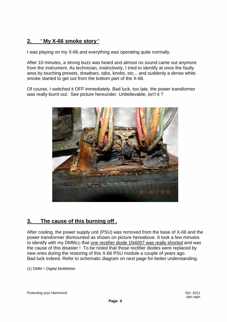
2. ' My X-66 smoke story ' I was playing on my X-66 and everything was operating quite normally. After 10 minutes, a strong buzz was heard and almost no sound came out anymore from the instrument. As technician, instinctively, I tried to identify at once the faulty area by touching presets, drawbars, tabs, knobs, etc... and suddenly a dense white smoke started to get out from the bottom part of the X-66. Of course, I switched it OFF immediately. Bad luck, too late, the power transformer was really burnt out. See picture hereunder. Unbelievable, isn't it ?
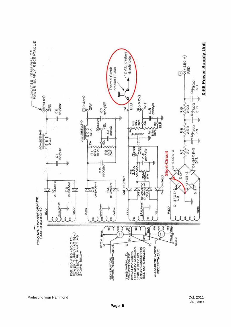
3. The cause of this burning off . After cooling, the power supply unit (PSU) was removed from the base of X-66 and the power transformer dismounted as shown on picture hereabove. It took a few minutes to identify with my DMM(1) that one rectifier diode 1N4007 was really shorted and was the cause of this disaster ! To be noted that those rectifier diodes were replaced by new ones during the restoring of this X-66 PSU module a couple of years ago. Bad luck indeed. Refer to schematic diagram on next page for better understanding. (1) DMM = Digital MultiMeter
Protecting your Hammond Oct. 2011 dan.vigin
Page 5
Protecting your Hammond Oct. 2011 dan.vigin
Page 6
4. Lessons learnt from this situation. - The Hammond X-66 is not equipped with adequate protection device to prevent from burning out the power transformer in case of unexpected event. Here is the evidence, one defective rectifier diode may cause severe damages to electronic circuits in the whole organ. - Measurements taken on the secondary windings of the power transformer show that the first secondary winding (BLU-BLU/WHT-BLU) and the fourth secondary winding (RED-RED) were also found in short-circuit as a consequence of this the burnt out (measured less than 10 ohms between windings). Those two windings are feeding high voltages in the whole organ. Luckily, those two windings were not in contact with the two other low voltage windings. Imagine that if one of those two high-voltage windings would have been in direct contact with the low-voltage windings, all semi-conductors (transistors, diodes, IC's,..) and low-voltages capacitors would also have blown instantaneously and ...
the whole organ would become practically unrepairab le ! - The only protection available in the Hammond X-66 is one thermal circuit breaker LT340 of the outlet box and installed in the " –12 Vdc " line and that is even omitted on the main schematic diagram. The only trail of this circuit breaker only appears on drawing 5-11 showing the wiring of the power receptacle. Nothing else. This circuit breaker is only protecting the following solenoids and relays :
- 3 x relays for Sforzando - 1 x relay for Tibia - 2 x solenoids for 'ORCH' and 'ACCOMP' - 3 x solenoids for Scanner V1,V2 and V3
This circuit breaker has been added on the schematic diagram, refer to previous page. It's a Slow-Blow thermal circuit breaker supposed to operate in the range of 3.5 A to 5A at 250 V max. and can be reset if any. 5. Actions to be taken. Before going any further, it is important to get some parameters of this transformer. Evidently, no data are available and by pure guesswork and some measurements, it is possible to come up with the following information. The apparent power of this transformer is estimated at 250 VA with an efficiency of about 80 to 90 %. The DC resistance of the low voltage secondary windings is extremely low (less than 1.6 ohm). The DC resistance of the high voltage secondary windings is below 15 ohms. The DC resistance of each primary winding is about 3.5 ohm.
Protecting your Hammond Oct. 2011 dan.vigin
Page 7
6. Basics about Protection Fuses. The purpose of this chapter is not to provide a complete theory on protection fuses. For those who want to get more technical details of protection devices, refer to the following websites: http://en.wikipedia.org/wiki/Fuse , (select 'electrical') and/or www.littelfuse .com/data/en/Product_Catalogs/Fuseology .169-198.pdf At the first sight, fuses look to be the simplest component in any electronic equipment. That's totally true. However, to be efficient, fuses must be properly selected. In the case that we are concerned with, the three following basic parameters have to be taken into consideration: 6.1. Nominal current rating : that is the current rating expressed either in Amperes (A) or milliamperes (mA) for which the fuse has been calibrated. 6.2. Response -Time : that is the time left before fuse melting in function of a certain current flow during a concerned period of time. Fuses are generally categorized as follows: FF type = very Fast action, below 1 mSec. F type = Fast action, between 1 mSec and 10 mSec. M type = Normal action in the range of 30 mSec. T type = Slow-Blow or delayed action, between 10 mSec and 100 mSec.
(also called 'temporized' or 'time-lag' fuses). Slow-Blow fuses incorporate a thermal delay.
TT type = Very Slow-Blow action, between 100 mSec and 1 Sec. 6.3. Voltage rating : that is the voltage at which the fuse is designed to operate. Using 250 Vac fuses would suit for both US and EUR organs since voltages involved are less than their rating voltages. There is no rule for applying AC fuses in DC circuits such as applying the fuse at its half AC voltage rating. Ideally, fuses used in DC circuits should have DC ratings ! (info: www.littlefuse.com). Of course, many other parameters related to specifications of fuses are available however in our particular study case, there are no so relevant and are not taken into consideration. Let us focus our attention mostly on the Response-Time characteristics. The Nominal Current rating and the Voltage rating will be covered later on. In our particular application, only and Slow-Blow (T) and Fast types (F) will be taken into account and are described hereafter.
Protecting your Hammond Oct. 2011 dan.vigin
Page 8
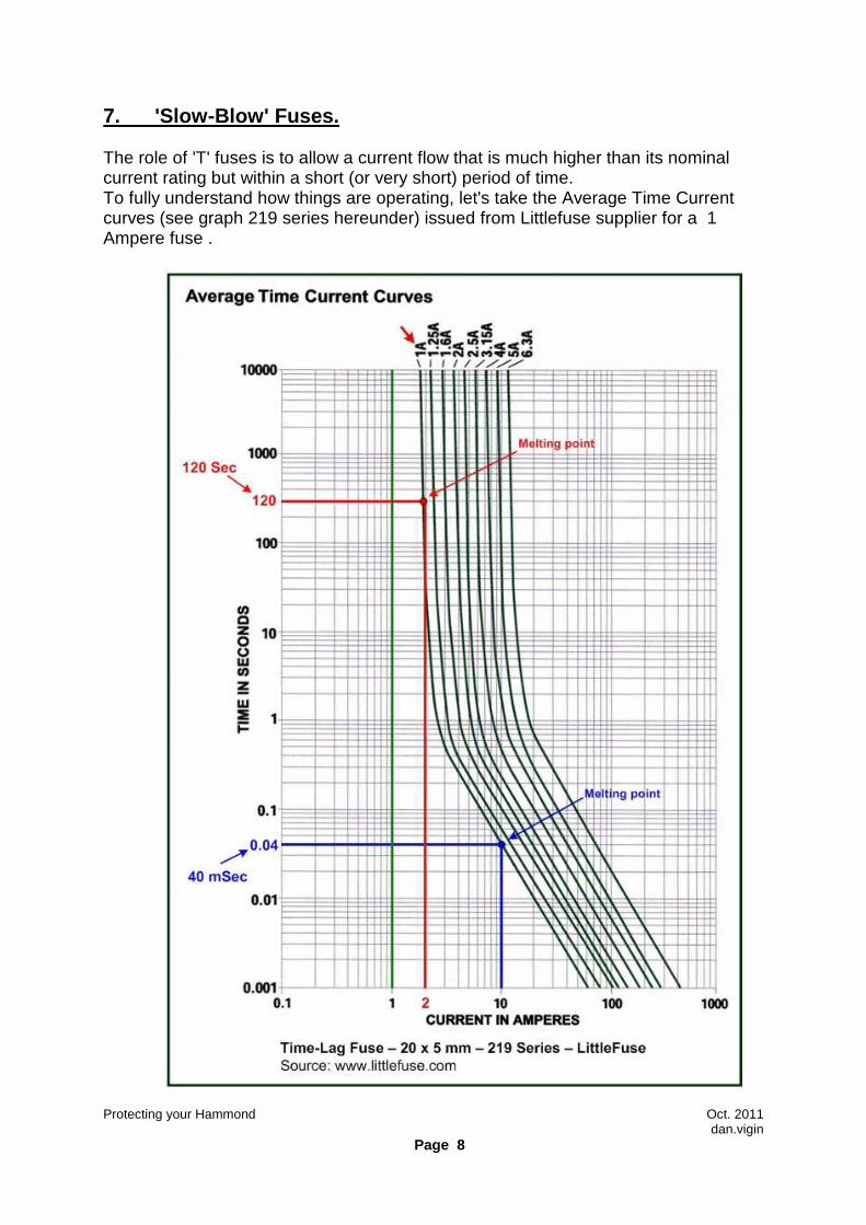
7. 'Slow-Blow' Fuses. The role of 'T' fuses is to allow a current flow that is much higher than its nominal current rating but within a short (or very short) period of time. To fully understand how things are operating, let's take the Average Time Current curves (see graph 219 series hereunder) issued from Littlefuse supplier for a 1 Ampere fuse .
Protecting your Hammond Oct. 2011 dan.vigin
Page 9
- Since the nominal current rating is 1AT (stands for 1 Ampere Slow-Blow type), it easy to notice on the graph that, in principle, with a 1 Ampere current flow, the fuse will never blow (green line) since located on the left end side of the 1A curve. - For any reason, if the nominal current increases up to 2 Amperes, then the red line hits the time current curve at 120 seconds and the fuse will melt down at that moment. This means that fusion or melting point will be attained after two minutes when the nominal current flow will be doubled. - Furthermore, if one increases the nominal current up to 10 Amperes, then by folllowing the blue line, it's now easy to deduct that this fuse will blow after 40 mSec.
As a simple statement of fact, we can deduct that 'T' fuses may absorb a quite high peak of current during a very short period of time without blowing. Those 'T' fuses will be then used in circuits having 'inrush' current applications (or short duration surges of current) when switching ON motors, standard EI and toroidal transformers, charges of electrolytic capacitors, etc... With the help of this graph, we can also deduct that if we know that a measured 'inrush' current of a power transformer is 50 amperes during 20 mSec (i.e. first cycle of a 50 Hz AC mains frequency), even the nominal current of this transformer is 1 ampere after steady state, one 3.15 AT or 4 ampere fuse must be installed in that particular circuit ! Of course, this is a pure theoritical standpoint because, in reality, the inrush current is also upstream limited by the internal resistance of the whole household AC mains installation itself and other factors such as contact resistance of power switches, AC mains sockets, AC mains circuit breakers, resistance of AC mains cords, etc... 8. Fast or 'F' Fuses. Contrarily to 'T' fuses, the role of 'F' fuses is to react instantaneously to any fast surge of current that is higher than its nominal current rating within a short (or very short) period of time. To fully understand how things are operating, let's take the Average Time Current curves (see graph 235 series on next page) and issued by Littlefuse supplier for a the same 1 Ampere fuse value.
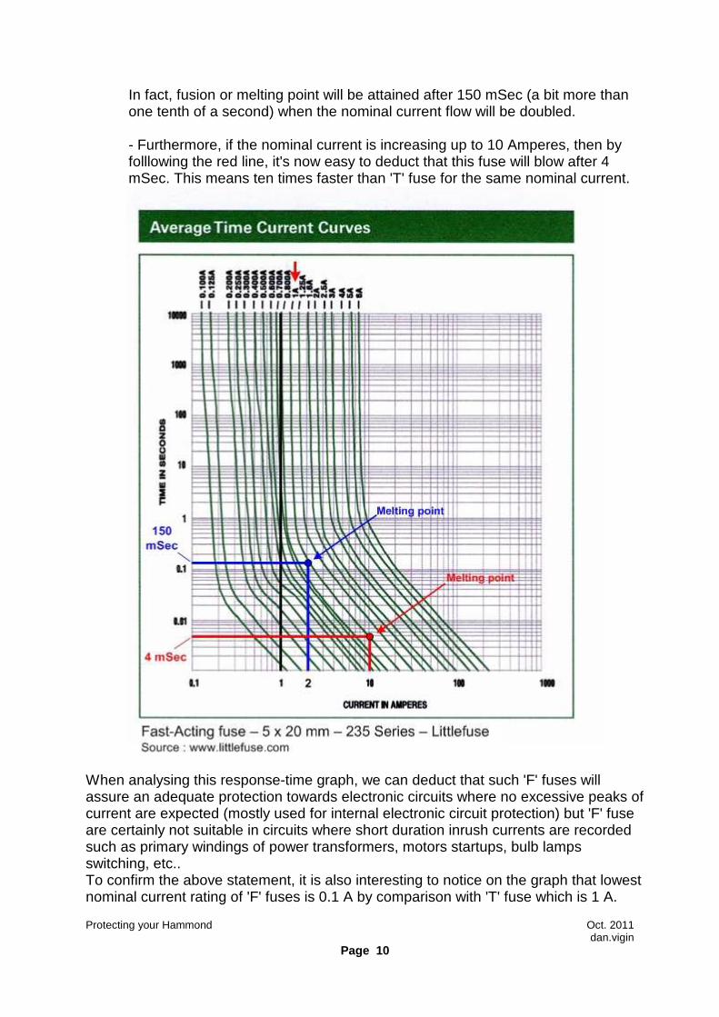
- Similarly to 'T' fuses, since the nominal current is rated for 1AF (stands for 1 Ampere Fast-acting type), it easy to notice on the graph that, in principle, with a 1 Ampere current flow, the fuse will never blow (balck line) since located on the left side of the 1A curve. - For any reason, if the nominal current suddenly increases up to 2 Ampere, then the blue line hits the time current curve at 150 mSec and the fuse will melt down at that moment. This means 800 times faster than the 'T' fuse for the same nominal current !
Protecting your Hammond Oct. 2011 dan.vigin
Page 10
In fact, fusion or melting point will be attained after 150 mSec (a bit more than one tenth of a second) when the nominal current flow will be doubled. - Furthermore, if the nominal current is increasing up to 10 Amperes, then by folllowing the red line, it's now easy to deduct that this fuse will blow after 4 mSec. This means ten times faster than 'T' fuse for the same nominal current.
When analysing this response-time graph, we can deduct that such 'F' fuses will assure an adequate protection towards electronic circuits where no excessive peaks of current are expected (mostly used for internal electronic circuit protection) but 'F' fuse are certainly not suitable in circuits where short duration inrush currents are recorded such as primary windings of power transformers, motors startups, bulb lamps switching, etc.. To confirm the above statement, it is also interesting to notice on the graph that lowest nominal current rating of 'F' fuses is 0.1 A by comparison with 'T' fuse which is 1 A.
Protecting your Hammond Oct. 2011 dan.vigin
Page 11
9. Good engineering practices: - Always replace the defective fuse with a fuse having the same nominal current rating and identical time-response characteristics i.e. 'T' , 'F', 'M'... - Never replace any 'F' fuse by a 'T' fuse. Conversely, a 'T' fuse can be replaced by a 'F' fuse. Indeed, the circuit will be so better (faster) protected however, such 'F' fuses will be certainly replaced more frequently for the reasons explained hereabove. - Reliability of fuses also depends on ambient temperature (generally 25 °C). The higher the ambient temperature, the hotter the fuse will operate and the shorter its life. If operated at no more than 75% of fuse rating, fuses at room temperature should last indefinitively. For example, a normal operating current of 2.25 amperes in a certain application should be divided by 0.75 and then select a 3 Amp. fuse or the nearest value. (Source LittleFuse Selection Guide). In short, simply divide the measured current at steady state by a factor of 0.75 to get the proper nominal current rating. - Always have on hand spare fuses with same characteristics. 10. Elements to be protected : The question is " What do we intend to protect ? " - the house against fire, the instrument, - only the power transformer - the power transformer and its associated power supply unit - the electronic circuitry alone behind the power supply or all of the above ? Like always, the common sense dictates that the correct answer is a matter of compromise of all of them. In fact, installation of too many protection fuses will create more problems than they solve. Inadequate or unsufficient protection devices will not help either.
AC
Transformer
Power Supply
Unit
Circuit #3AC Mains
Circuit #1
Circuit #2
A
B C
D
D
D
Protecting your Hammond Oct. 2011 dan.vigin
Page 12
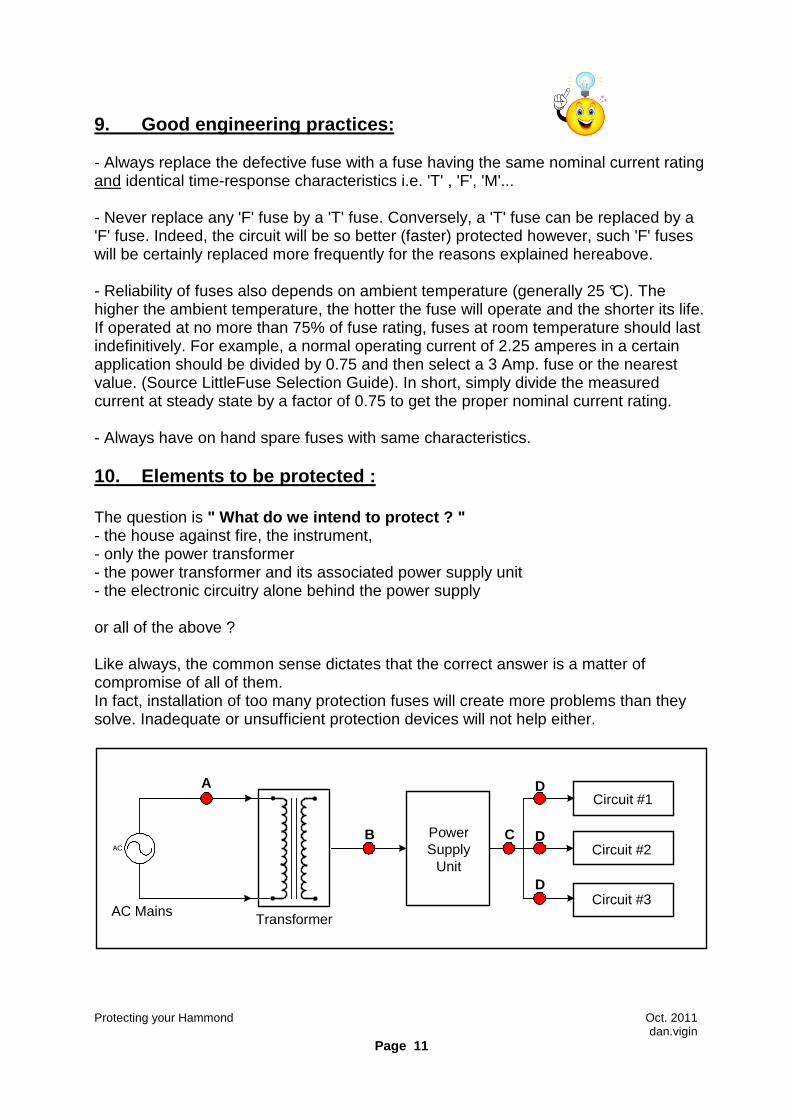
Protection devices may be installed at different levels in the instrument:
- Pt.A - firstly at Primary side of the power transformer - Pt.B - between the secondary windings and the rectifier bridges, filter cap's, regulators, etc.. - Pt.C - after rectifying, filtering, regulating - Pt.D - or even to each individual circuit
In the case of the Hammond X-66, installation of fuses to protect each discrete circuit will be a total nonsense. It would require several hundreds fuses ! So, we simply forget of this solution at Pt. D for this concerned instrument. About of inrush current measurements. During this study, of inrush current measurements were conducted on several other transformers than the one installed on the Hammond X-66 and from those tests it appears that: - Max. inrush current of a 1KVA toroidal transformer was about 52 A (unloaded). Inrush current greatly depends on the moment that it is switched ON during the cycle. - Max. inrush current of the X-66 transformer ( EI core, +/- 250 VA) was 11 A .
Protecting your Hammond Oct. 2011 dan.vigin
Page 13
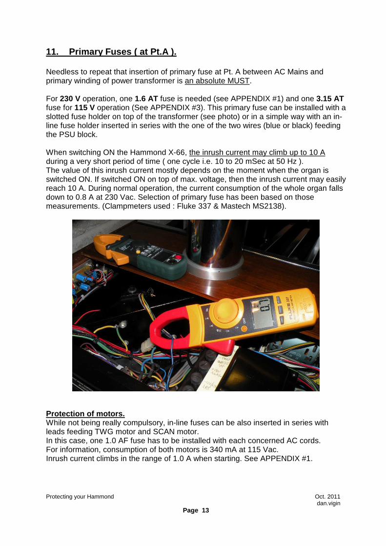
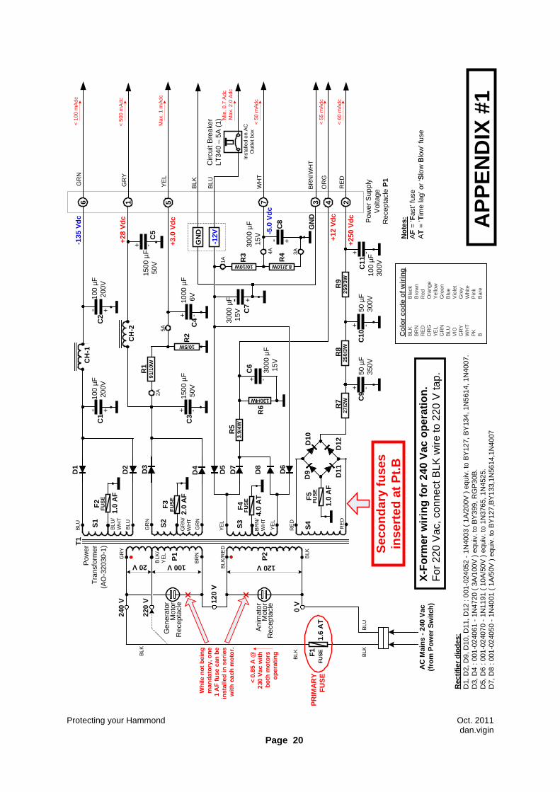
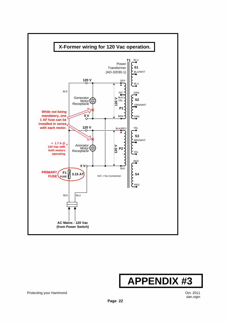
11. Primary Fuses ( at Pt.A ). Needless to repeat that insertion of primary fuse at Pt. A between AC Mains and primary winding of power transformer is an absolute MUST. For 230 V operation, one 1.6 AT fuse is needed (see APPENDIX #1) and one 3.15 AT fuse for 115 V operation (See APPENDIX #3). This primary fuse can be installed with a slotted fuse holder on top of the transformer (see photo) or in a simple way with an in-line fuse holder inserted in series with the one of the two wires (blue or black) feeding the PSU block. When switching ON the Hammond X-66, the inrush current may climb up to 10 A during a very short period of time ( one cycle i.e. 10 to 20 mSec at 50 Hz ). The value of this inrush current mostly depends on the moment when the organ is switched ON. If switched ON on top of max. voltage, then the inrush current may easily reach 10 A. During normal operation, the current consumption of the whole organ falls down to 0.8 A at 230 Vac. Selection of primary fuse has been based on those measurements. (Clampmeters used : Fluke 337 & Mastech MS2138).
Protection of motors. While not being really compulsory, in-line fuses can be also inserted in series with leads feeding TWG motor and SCAN motor. In this case, one 1.0 AF fuse has to be installed with each concerned AC cords. For information, consumption of both motors is 340 mA at 115 Vac. Inrush current climbs in the range of 1.0 A when starting. See APPENDIX #1.
Protecting your Hammond Oct. 2011 dan.vigin
Page 14
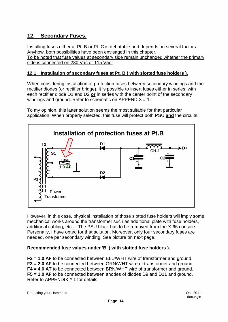
12. Secondary Fuses. Installing fuses either at Pt. B or Pt. C is debatable and depends on several factors. Anyhow, both possibilities have been envisaged in this chapter. To be noted that fuse values at secondary side remain unchanged whether the primary side is connected on 230 Vac or 115 Vac. 12.1 Installation of secondary fuses at Pt. B ( wit h slotted fuse holders ). When considering installation of protection fuses between secondary windings and the rectifier diodes (or rectifier bridge), it is possible to insert fuses either in series with each rectifier diode D1 and D2 or in series with the center point of the secondary windings and ground. Refer to schematic on APPENDIX # 1. To my opinion, this latter solution seems the most suitable for that particular application. When properly selected, this fuse will protect both PSU and the circuits.
T1
FUSE
Power Transformer
+
-+
-CH-1
D1
D2
C1 C2S1
1.0 AF
B+
P1
Installation of protection fuses at Pt.B
However, in this case, physical installation of those slotted fuse holders will imply some mechanical works around the transformer such as additional plate with fuse holders, additional cabling, etc.... The PSU block has to be removed from the X-66 console. Personally, I have opted for that solution. Moreover, only four secondary fuses are needed, one per secondary winding. See picture on next page. Recommended fuse values under 'B' ( with slotted fu se holders ). F2 = 1.0 AF to be connected between BLU/WHT wire of transformer and ground. F3 = 2.0 AF to be connected between GRN/WHT wire of transformer and ground. F4 = 4.0 AT to be connected between BRN/WHT wire of transformer and ground. F5 = 1.0 AF to be connected between anodes of diodes D9 and D11 and ground. Refer to APPENDIX # 1 for details.
Protecting your Hammond Oct. 2011 dan.vigin
Page 15
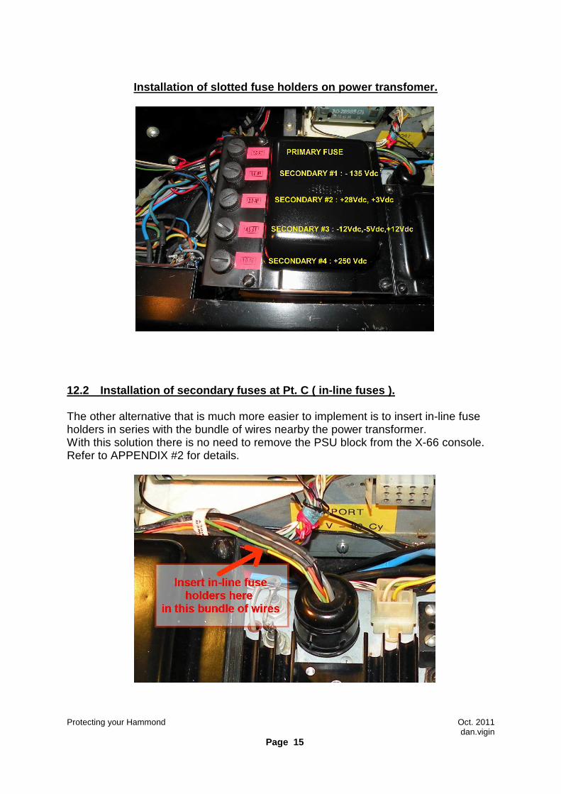
Installation of slotted fuse holders on power trans fomer.
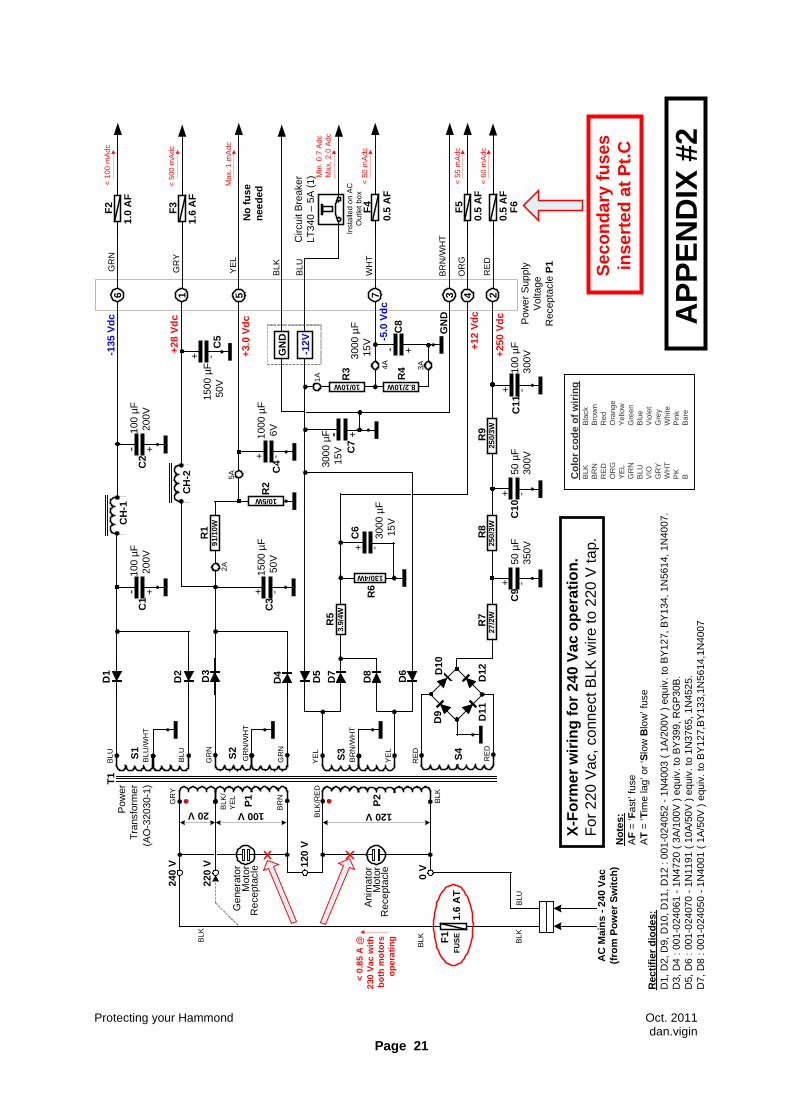
12.2 Installation of secondary fuses at Pt. C ( in- line fuses ). The other alternative that is much more easier to implement is to insert in-line fuse holders in series with the bundle of wires nearby the power transformer. With this solution there is no need to remove the PSU block from the X-66 console. Refer to APPENDIX #2 for details.
Protecting your Hammond Oct. 2011 dan.vigin
Page 16
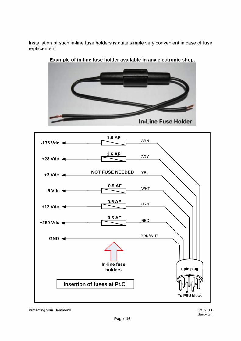
Installation of such in-line fuse holders is quite simple very convenient in case of fuse replacement.
Example of in-line fuse holder available in any ele ctronic shop.
BRN/WHT
GRY
RED
7-pin plug
ORN
YEL
GRN
WHT
In-line fuse holders
1.6 AF
Insertion of fuses at Pt.C
NOT FUSE NEEDED
0.5 AF-5 Vdc
+28 Vdc
+250 Vdc
GND
+12 Vdc
+3 Vdc
-135 Vdc
0.5 AF
To PSU block
1.0 AF
0.5 AF
Protecting your Hammond Oct. 2011 dan.vigin
Page 17
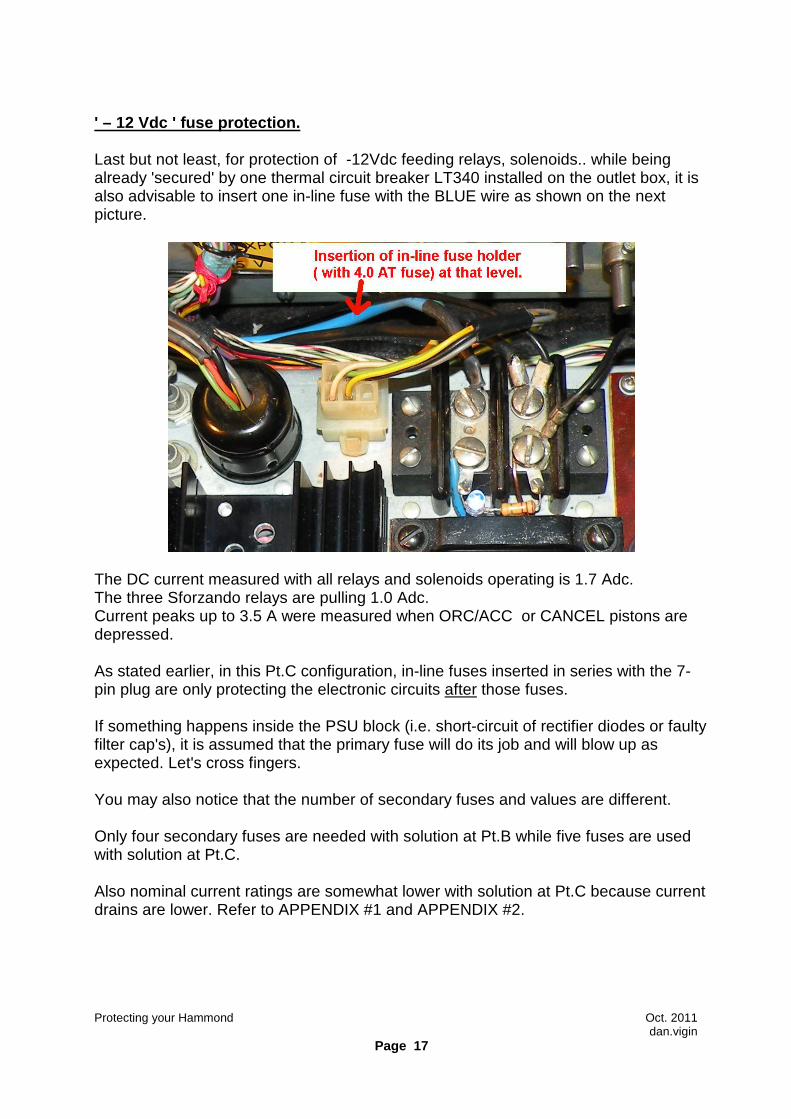
' – 12 Vdc ' fuse protection. Last but not least, for protection of -12Vdc feeding relays, solenoids.. while being already 'secured' by one thermal circuit breaker LT340 installed on the outlet box, it is also advisable to insert one in-line fuse with the BLUE wire as shown on the next picture.
The DC current measured with all relays and solenoids operating is 1.7 Adc. The three Sforzando relays are pulling 1.0 Adc. Current peaks up to 3.5 A were measured when ORC/ACC or CANCEL pistons are depressed. As stated earlier, in this Pt.C configuration, in-line fuses inserted in series with the 7-pin plug are only protecting the electronic circuits after those fuses. If something happens inside the PSU block (i.e. short-circuit of rectifier diodes or faulty filter cap's), it is assumed that the primary fuse will do its job and will blow up as expected. Let's cross fingers. You may also notice that the number of secondary fuses and values are different. Only four secondary fuses are needed with solution at Pt.B while five fuses are used with solution at Pt.C. Also nominal current ratings are somewhat lower with solution at Pt.C because current drains are lower. Refer to APPENDIX #1 and APPENDIX #2.
Protecting your Hammond Oct. 2011 dan.vigin
Page 18
13. Conclusions. In this chapter, it is rather easy to deduct that several levels of protection are possible and may be summarized as follows: 1. Optimal level : full secure solution including primary fuse, secondary fuses (either insertion of fuses at Pt.C or preferably at Pt.B), two fuses to protect both motors and one in-line fuse in series with the ' – 12 Vdc ' powering the relays and solenoids. 2. Average level : including one primary fuse and insertion of fuses at Pt.C or preferably at Pt.B whenever possible due to mechanical works involved. 3. Minimum level : absolute necessity to install at once one in-line primary fuse of 1.6 AT (for 230 V operation) and 3.15 AT (for 115 V operation). This action can be done in less than half an hour by any service technician and is a real MUST. After having replaced this burnt out transformer and installed protection fuses, I decided to investigate deeply this situation and start preparing this chapter. However I never imagined that it was possible to write 22 pages on such a basic circuit that apparently looked quite simple but after investigations it is not. We all know that under normal operating conditions, protection fuses are totally useless, just like 'the fift spare wheel of the car'. Nevertheless, when a major component like a rectifier diode or filter cap becomes suddenly defective then the role of protection fuse becomes really appreciated. ' Prevention is always better than cure' Dan Vigin Good to know... This chapter is continued by another one entitled ' Improving the Power Supply Unit of Hammond X-66 '.
Protecting your Hammond Oct. 2011 dan.vigin
Page 19
14. Acknowledgements I would like to take this opportunity to thank professors Mr.B.Conil and Mr.G.Duhem of I.D.B. of Tournai, Belgium for their contribution in this study as well as Mr.Sjaak Van Oosterhout, general manager of Musifix of Reusel, The Netherlands for having supplied a replacement X-66 transformer. Final Joke ! When I was working for MARANTZ Inc., as responsible of safety regulations, during a meeting, a Japanese engineer said: ' In Japan, recently we have developed the most reliable fuses in the world since they never blow up '. OUPS.....
Protecting your Hammond Oct. 2011 dan.vigin
Page 20
T1
RE
D
-
BR
N
BLK
/Y
EL
GR
Y
BLK
BLK
/RE
D
BLU BLU
BLU
/W
HT
GR
N
GR
N
GR
N/
WH
T
YE
L
YE
L
BR
N/
WH
T
RE
D
120 V20 V 100 V
Ani
mat
or
Rec
epta
cle
Mot
or
Pow
er
Tra
nsfo
rmer
Rec
epta
cle
Mot
orG
ener
ator
(AO
-320
30-1
)
+ -
3.9/
4W
130/4W
10/10W 8.2/10W
+ -
+ -
27/2
W25
0/3W
250/
3W
+ -
+- + -
+-
91/1
0W
10/5W
+ -
+ -
+
CH
-1
CH
-2
D1
D2
D3
D6
D4
D5
D10
D7
D8
D9
D12
D11
R2
R7
R8
R9
R1
R3
R4
R5
R6
+3.0
Vdc
C1
C2
C3
C4
C5
C6
C7
C8
C9
C10
C11
6 1 5 7 3 4 2
-12V
GN
D
1500
µF
50V
100
µF
200
V10
0 µ
F 2
00V
1500
µF
50V
1000
µF
6V
3000
µF
15V
3000
µF
15V
AC
Mai
ns -
240
Vac
(f
rom
Pow
er S
witc
h)
50 µ
F35
0V50
µF
300V
BLU
100
µF
300V
3000
µF
15V
Pow
er S
uppl
yV
olta
ge
Rec
epta
cle
P1
+-
2A5A
1A
4A 3A
-135
Vdc
+28
Vdc
-5.0
Vdc
GN
D
+12
Vdc
+250
Vdc
Circ
uit B
reak
er
LT34
0 –
5A (
1)
GR
N
GR
Y
YE
L
BLU
BLK
WH
T
BR
N/W
HT
OR
G
RE
D
Col
or c
ode
of w
iring
B
LK
Bla
ckB
RN
Bro
wn
RE
DR
edO
RG
Ora
nge
YE
LY
ello
wG
RN
Gre
enB
LUB
lue
VIO
Vio
let
GR
YG
rey
WH
TW
hite
PK
Pin
kB
Bar
e
BLK
Inst
alle
d on
AC
O
utle
t box
Rec
tifie
r di
odes
:D
1, D
2, D
9, D
10, D
11, D
12 :
001-
0240
52 -
1N
4003
( 1
A/2
00V
) e
quiv
. to
BY
127,
BY
134,
1N
5614
, 1N
4007
.D
3, D
4 : 0
01-0
2406
1 -
1N47
20 (
3A
/100
V )
equ
iv. t
o B
Y39
9, R
GP
30B
.D
5, D
6 : 0
01-0
2407
0 -
1N11
91 (
10A
/50V
) e
quiv
. to
1N37
65, 1
N45
25.
D7,
D8
: 001
-024
050
- 1N
4001
( 1
A/5
0V )
equ
iv. t
o B
Y12
7,B
Y13
3,1N
5614
,1N
4007
240
V
0 V12
0 V
220
V
X-F
orm
er w
iring
for
240
Vac
ope
ratio
n.F
or 2
20 V
ac, c
onne
ct B
LK w
ire to
220
V ta
p.
BLK
P1
P2
S1
S2
S3
S4
1.6
AT
F1
FU
SE
Min
. 0.7
Adc
M
ax. 2
.0 A
dc
< 60
mA
dc
< 55
mA
dc
< 50
mA
dc
Max
. 1 m
Adc
< 5
00 m
Adc
< 1
00 m
Adc
Not
es:
AF
= ‘F
ast’
fuse
AT
= ‘T
ime
lag’
or
‘Slo
w B
low
’ fus
e
< 0.
85 A
@23
0 V
ac w
ith
both
mot
ors
oper
atin
g
Whi
le n
ot b
eing
m
anda
tory
, one
1
AF
fuse
can
be
inst
alle
d in
ser
ies
with
eac
h m
otor
.
BLK
PR
IMA
RY
F
US
E
FU
SE
1.0
AF
F2
FU
SE
2.0
AF
F3
FU
SE
4.0
AT
F4 F
US
E
1.0
AF
F5
Sec
onda
ry fu
ses
inse
rted
at P
t.B
AP
PE
ND
IX #
1
Protecting your Hammond Oct. 2011 dan.vigin
Page 21
T1
RE
D
-
BR
N
BLK
/Y
EL
GR
Y
BLK
BLK
/RE
D
BLU BLU
BLU
/WH
T
GR
N
GR
N
GR
N/W
HT
YE
L
YE
L
BR
N/W
HT
RE
D
120 V20 V 100 V
Ani
mat
or
Rec
epta
cle
Mot
or
Pow
er
Tra
nsfo
rmer
Rec
epta
cle
Mot
orG
ener
ator
(AO
-320
30-1
)
+ -
3.9/
4W
130/4W
10/10W 8.2/10W
+ -
+ -
27/2
W25
0/3W
250/
3W
+ -
+- + -
+-
91/1
0W
10/5W
+ -
+ -
+
CH
-1
CH
-2
D1
D2
D3
D6
D4
D5 D
10
D7
D8
D9
D12
D11
R2
R7
R8
R9
R1
R3
R4
R5
R6
+3.0
Vdc
C1
C2
C3
C4
C5
C6
C7
C8
C9
C10
C11
6 1 5 7 3 4 2
-12V
GN
D
1500
µF
50V
100
µF
200
V10
0 µ
F 2
00V
1500
µF
50V
1000
µF
6V
3000
µF
15V
3000
µF
15V
AC
Mai
ns -
240
Vac
(f
rom
Pow
er S
witc
h)
50 µ
F35
0V50
µF
300V
BLU
100
µF
300V
3000
µF
15V
Pow
er S
uppl
yV
olta
ge
Rec
epta
cle
P1
+-
2A5A
1A
4A 3A
-135
Vdc
+28
Vdc
-5.0
Vdc
GN
D
+12
Vdc
+250
Vdc
Circ
uit B
reak
er
LT34
0 –
5A (
1)
GR
N
GR
Y
YE
L
BLU
BLK
WH
T
BR
N/W
HT
OR
G
RE
D
Col
or c
ode
of w
iring
B
LK
Bla
ckB
RN
Bro
wn
RE
DR
edO
RG
Ora
nge
YE
LY
ello
wG
RN
Gre
enB
LUB
lue
VIO
Vio
let
GR
YG
rey
WH
TW
hite
PK
Pin
kB
Bar
e
BLK
Inst
alle
d on
AC
O
utle
t box
Rec
tifie
r di
odes
:D
1, D
2, D
9, D
10, D
11, D
12 :
001-
0240
52 -
1N
4003
( 1
A/2
00V
) e
quiv
. to
BY
127,
BY
134,
1N
5614
, 1N
4007
.D
3, D
4 : 0
01-0
2406
1 -
1N47
20 (
3A
/100
V )
equ
iv. t
o B
Y39
9, R
GP
30B
.D
5, D
6 : 0
01-0
2407
0 -
1N11
91 (
10A
/50V
) e
quiv
. to
1N37
65, 1
N45
25.
D7,
D8
: 001
-024
050
- 1N
4001
( 1
A/5
0V )
equ
iv. t
o B
Y12
7,B
Y13
3,1N
5614
,1N
4007
240
V
0 V12
0 V
220
V
X-F
orm
er w
iring
for
240
Vac
ope
ratio
n.F
or 2
20 V
ac, c
onne
ct B
LK w
ire to
220
V ta
p.
BLK
P1
P2
S1
S2
S3
S4
1.6
AT
1.6
AF
1.0
AF
0.5
AF
0.5
AF
0.5
AF
F1
FU
SE
F2
F3 F5
F6
Min
. 0.7
Adc
M
ax. 2
.0 A
dc
< 60
mA
dc
< 55
mA
dc
< 50
mA
dc
Max
. 1 m
Adc
< 5
00 m
Adc
< 1
00 m
Adc
Not
es:
AF
= ‘F
ast’
fuse
AT
= ‘T
ime
lag’
or
‘Slo
w B
low
’ fus
e
< 0.
85 A
@23
0 V
ac w
ith
both
mot
ors
oper
atin
g BLK
F4
Sec
onda
ry fu
ses
inse
rted
at P
t.C
No
fuse
ne
eded
AP
PE
ND
IX #
2
Protecting your Hammond Oct. 2011 dan.vigin
Page 22
T1
RED
BRN
BLK/YEL
GRY
BLK
BLK/RED
BLU
BLU
BLU/WHT
GRN
GRN
GRN/WHT
YEL
YEL
BRN/WHT
RED
120
V12
0 V
Animator
ReceptacleMotor
Power Transformer
ReceptacleMotor
Generator
(AO-32030-1)
AC Mains - 120 Vac (from Power Switch)
BLUBLK
0 V
120 V
0 V
120 V
N/CBLK
X-Former wiring for 120 Vac operation.
N/C = No ConnectionS4
S3
S2
S1
P1
P2
< 1.7 A @120 Vac with both motors
operating
F1FUSE
3.15 AT
While not being mandatory, one
1 AF fuse can be installed in series with each motor.
PRIMARY FUSE
APPENDIX #3

![Modular Samsung Max-x55 x56 x57 x65 x66 [ET]](https://static.fdocuments.us/doc/165x107/54e8d7d94a7959b17a8b4b02/modular-samsung-max-x55-x56-x57-x65-x66-et.jpg)