Protecting VFD Driven Motors from Bearing Currentsvibration.org/Presentation/Dec 2011/AEGIS...
31
Copyright 2010 – Electro Static Technology-ITW – Patented Technology – All Rights Reserved Copyright 2010 – Electro Static Technology-ITW – Patented Technology – All Rights Reserved Protecting VFD Driven Motors from Bearing Currents Shaft Grounding Rings
Transcript of Protecting VFD Driven Motors from Bearing Currentsvibration.org/Presentation/Dec 2011/AEGIS...
Copyright 2010 – Electro Static Technology-ITW – Patented Technology – All Rights Reserved Copyright 2010 – Electro Static Technology-ITW – Patented Technology – All Rights Reserved
Protecting VFD Driven Motors
from Bearing Currents
Shaft Grounding Rings
Copyright 2010 – Electro Static Technology-ITW – Patented Technology – All Rights Reserved Copyright 2010 – Electro Static Technology-ITW – Patented Technology – All Rights Reserved
Variable Frequency Drives
and Electric Induction Motors
When pulse width modulation (PWM) Variable Frequency Drives (VFDs) were developed using insulated gate bipolar transistors (IGBTs), this new technology was used to control electric induction motors in industrial and commercial applications. The advantages were obvious:
• Torque and motor speed could now be precisely controlled to
optimize both process and energy requirements.
• The potential to save energy by operating motors at only the
needed speed while maintaining torque requirements could
potentially result in a 20% to 50% energy savings.
• Processes could be optimized and controlled by computer
processing systems to achieve productivity increases or energy
savings.
2
Copyright 2010 – Electro Static Technology-ITW – Patented Technology – All Rights Reserved Copyright 2010 – Electro Static Technology-ITW – Patented Technology – All Rights Reserved
3
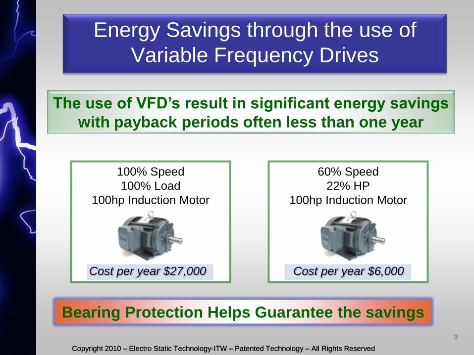
Energy Savings through the use of
Variable Frequency Drives
100% Speed
100% Load
100hp Induction Motor
Cost per year $27,000
60% Speed
22% HP
100hp Induction Motor
Cost per year $6,000
The use of VFD’s result in significant energy savings
with payback periods often less than one year
Bearing Protection Helps Guarantee the savings
Copyright 2010 – Electro Static Technology-ITW – Patented Technology – All Rights Reserved Copyright 2010 – Electro Static Technology-ITW – Patented Technology – All Rights Reserved
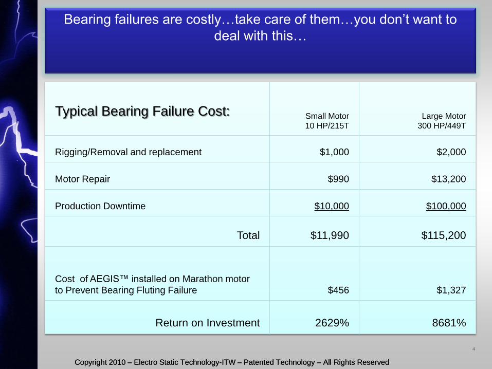
Bearing failures are costly…take care of them…you don’t want to
deal with this…
Typical Bearing Failure Cost:
Small Motor
10 HP/215T Large Motor
300 HP/449T
Rigging/Removal and replacement $1,000 $2,000
Motor Repair $990 $13,200
Production Downtime $10,000 $100,000
Total $11,990 $115,200
Cost of AEGIS™ installed on Marathon motor
to Prevent Bearing Fluting Failure $456 $1,327
Return on Investment 2629% 8681%
4

Copyright 2010 – Electro Static Technology-ITW – Patented Technology – All Rights Reserved Copyright 2010 – Electro Static Technology-ITW – Patented Technology – All Rights Reserved
Bearing Failure Reports
ABB Technical Guide No.5, 2000: “Some new drive installations can have their bearings fail only a few months after start-up…”
Emerson (US motors), Product service bulletin, Vol.3, Dec/2002: “In the past few years, there has been a significant increase in motor problems associated with shaft voltages and currents.”
WEG Electric Motors, June/2003: “Recently though, it has become apparent that these improvements have been bought at a price: IGBT technology has resurrected bearing problems due to electrical damage, creating a new challenge to manufacturers of electric motors…”
IEEE 2004, IAS 2004, 0-7803-8486-5/04: “The surfaces of the bearing races of bearings with operation time greater than 500 h are melted several times at the whole surface due to small craters…..”, A. Muetze, A.Binder, H.Vogel, J.Hering, “ Experimental Evaluation of the Endangerment of Ball Bearings due to Inverter-Induced Bearing Currents”, pp. 1989 – 1995
5
Copyright 2010 – Electro Static Technology-ITW – Patented Technology – All Rights Reserved Copyright 2010 – Electro Static Technology-ITW – Patented Technology – All Rights Reserved
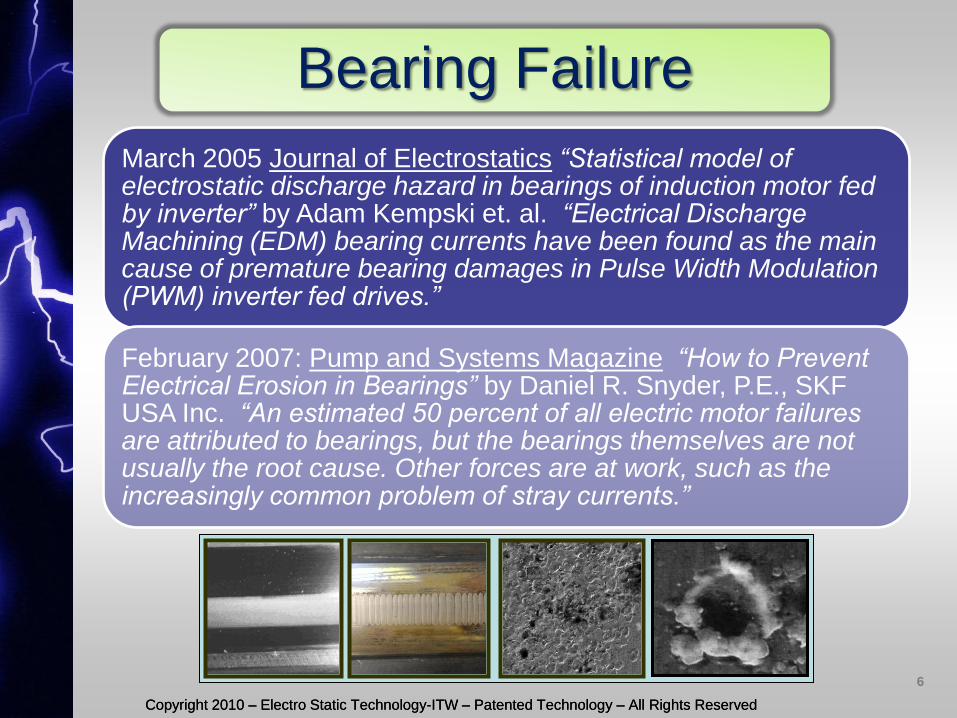
Bearing Failure
March 2005 Journal of Electrostatics “Statistical model of electrostatic discharge hazard in bearings of induction motor fed by inverter” by Adam Kempski et. al. “Electrical Discharge Machining (EDM) bearing currents have been found as the main cause of premature bearing damages in Pulse Width Modulation (PWM) inverter fed drives.”
February 2007: Pump and Systems Magazine “How to Prevent Electrical Erosion in Bearings” by Daniel R. Snyder, P.E., SKF USA Inc. “An estimated 50 percent of all electric motor failures are attributed to bearings, but the bearings themselves are not usually the root cause. Other forces are at work, such as the increasingly common problem of stray currents.”
6
Copyright 2010 – Electro Static Technology-ITW – Patented Technology – All Rights Reserved Copyright 2010 – Electro Static Technology-ITW – Patented Technology – All Rights Reserved
7
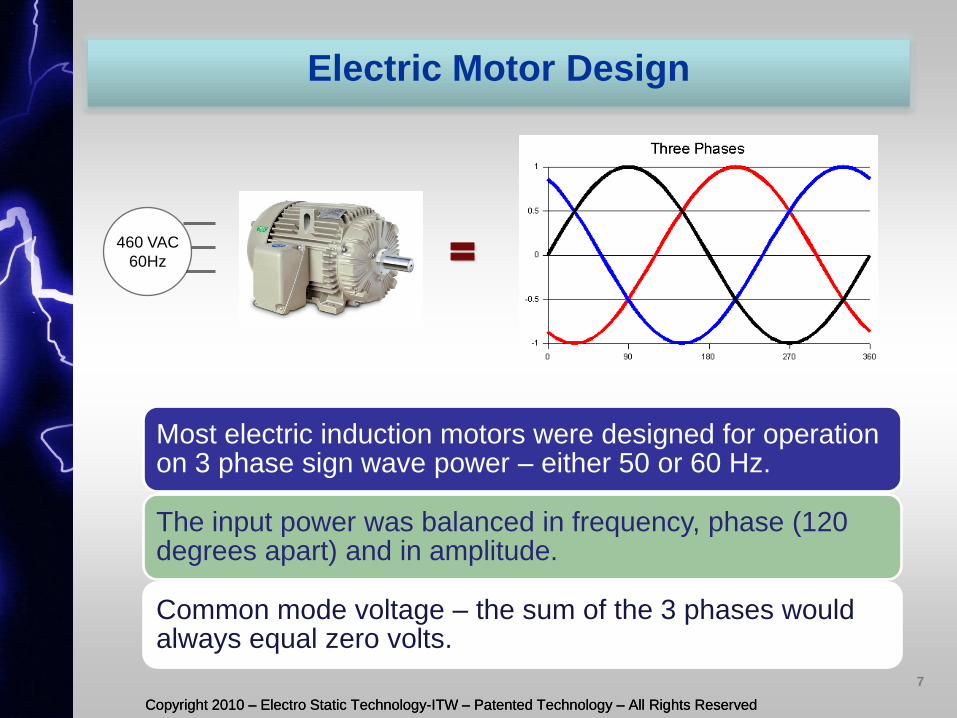
= 460 VAC
60Hz
Electric Motor Design
Most electric induction motors were designed for operation on 3 phase sign wave power – either 50 or 60 Hz.
The input power was balanced in frequency, phase (120 degrees apart) and in amplitude.
Common mode voltage – the sum of the 3 phases would always equal zero volts.
Copyright 2010 – Electro Static Technology-ITW – Patented Technology – All Rights Reserved Copyright 2010 – Electro Static Technology-ITW – Patented Technology – All Rights Reserved
8
+
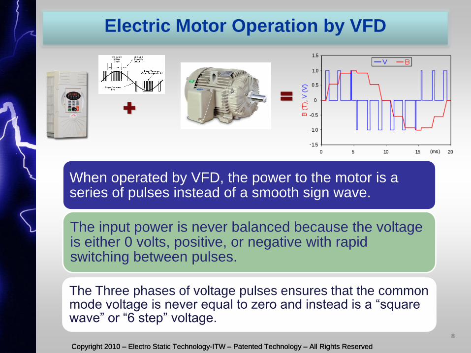
Electric Motor Operation by VFD
When operated by VFD, the power to the motor is a series of pulses instead of a smooth sign wave.
The input power is never balanced because the voltage is either 0 volts, positive, or negative with rapid switching between pulses.
The Three phases of voltage pulses ensures that the common mode voltage is never equal to zero and instead is a “square wave” or “6 step” voltage.
=
Copyright 2010 – Electro Static Technology-ITW – Patented Technology – All Rights Reserved
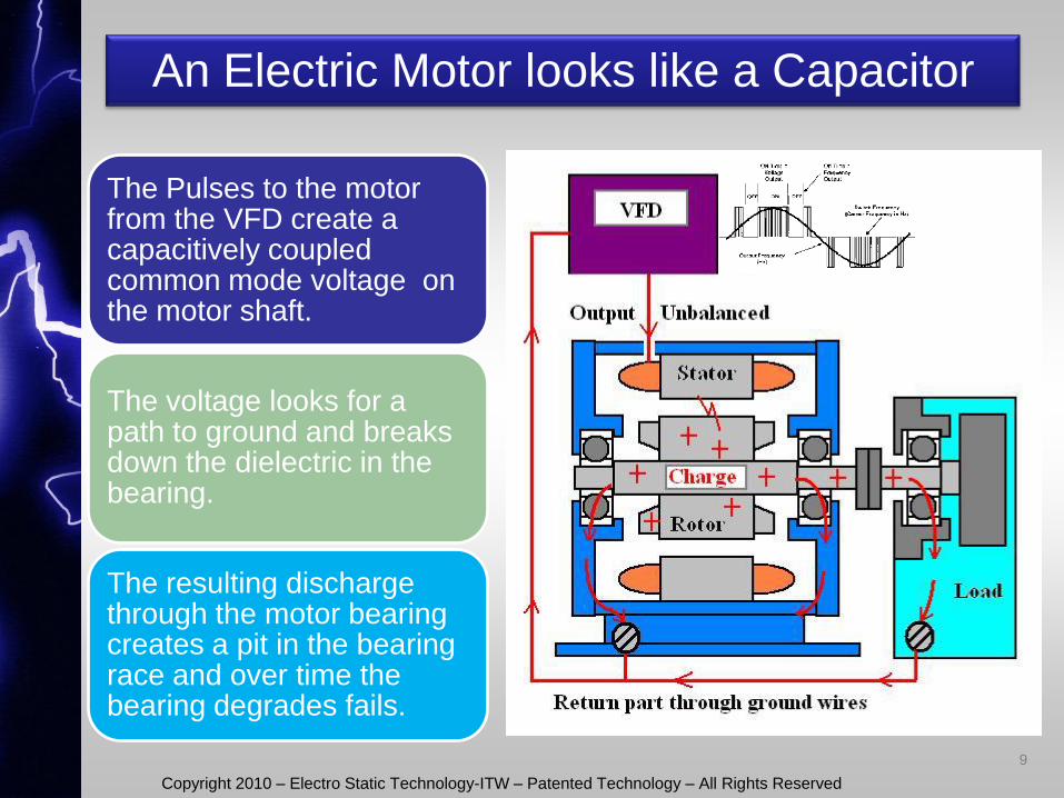
An Electric Motor looks like a Capacitor
The Pulses to the motor from the VFD create a capacitively coupled common mode voltage on the motor shaft.
The voltage looks for a path to ground and breaks down the dielectric in the bearing.
The resulting discharge through the motor bearing creates a pit in the bearing race and over time the bearing degrades fails.
9
Copyright 2010 – Electro Static Technology-ITW – Patented Technology – All Rights Reserved Copyright 2010 – Electro Static Technology-ITW – Patented Technology – All Rights Reserved
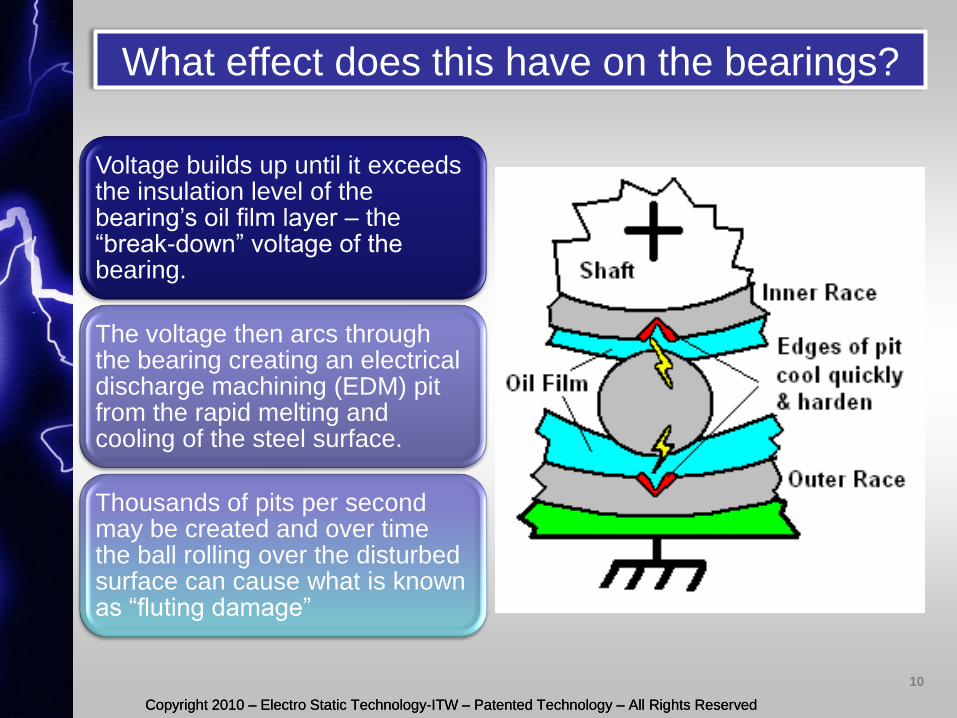
What effect does this have on the bearings?
Voltage builds up until it exceeds the insulation level of the bearing’s oil film layer – the “break-down” voltage of the bearing.
The voltage then arcs through the bearing creating an electrical discharge machining (EDM) pit from the rapid melting and cooling of the steel surface.
Thousands of pits per second may be created and over time the ball rolling over the disturbed surface can cause what is known as “fluting damage”
10
Copyright 2010 – Electro Static Technology-ITW – Patented Technology – All Rights Reserved Copyright 2010 – Electro Static Technology-ITW – Patented Technology – All Rights Reserved
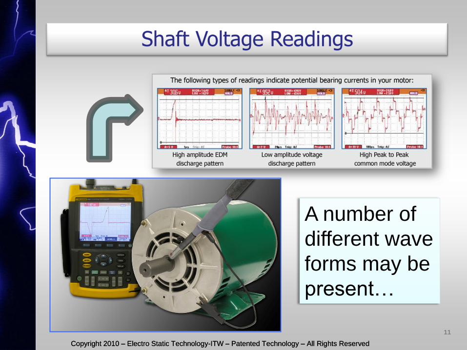
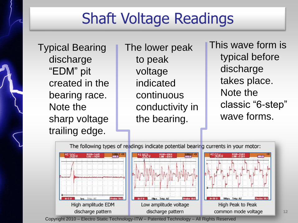
Shaft Voltage Readings
A number of
different wave
forms may be
present…
11
Copyright 2010 – Electro Static Technology-ITW – Patented Technology – All Rights Reserved
Typical Bearing
discharge
“EDM” pit
created in the
bearing race.
Note the
sharp voltage
trailing edge.
Shaft Voltage Readings
The lower peak
to peak
voltage
indicated
continuous
conductivity in
the bearing.
This wave form is
typical before
discharge
takes place.
Note the
classic “6-step”
wave forms.
12
Copyright 2010 – Electro Static Technology-ITW – Patented Technology – All Rights Reserved Copyright 2010 – Electro Static Technology-ITW – Patented Technology – All Rights Reserved
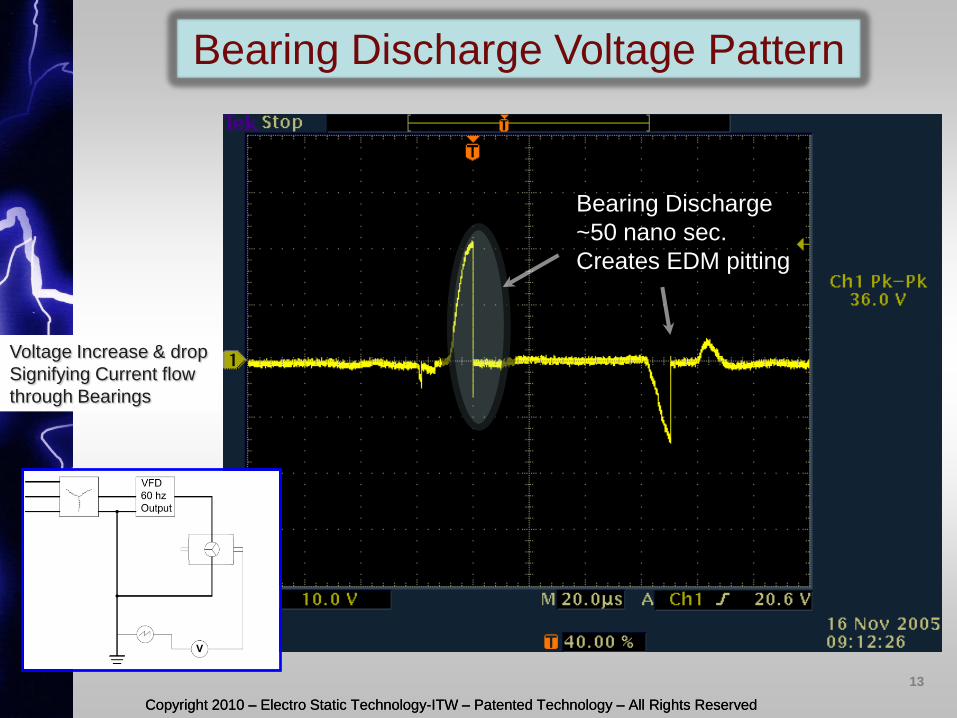
Bearing Discharge Voltage Pattern
Voltage Increase & drop
Signifying Current flow
through Bearings
Bearing Discharge
~50 nano sec.
Creates EDM pitting
13
Copyright 2010 – Electro Static Technology-ITW – Patented Technology – All Rights Reserved
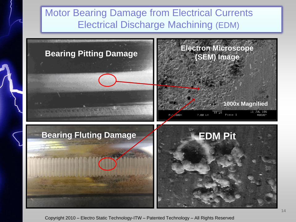
Motor Bearing Damage from Electrical Currents
Electrical Discharge Machining (EDM)
Bearing Pitting Damage
Bearing Fluting Damage
Electron Microscope
(SEM) Image
EDM Pitting
1000x Magnified
EDM Pit
14
Copyright 2010 – Electro Static Technology-ITW – Patented Technology – All Rights Reserved Copyright 2010 – Electro Static Technology-ITW – Patented Technology – All Rights Reserved
15
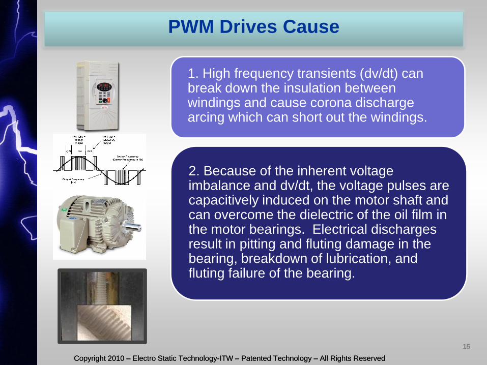
PWM Drives Cause
1. High frequency transients (dv/dt) can break down the insulation between windings and cause corona discharge arcing which can short out the windings.
2. Because of the inherent voltage imbalance and dv/dt, the voltage pulses are capacitively induced on the motor shaft and can overcome the dielectric of the oil film in the motor bearings. Electrical discharges result in pitting and fluting damage in the bearing, breakdown of lubrication, and fluting failure of the bearing.
Copyright 2010 – Electro Static Technology-ITW – Patented Technology – All Rights Reserved Copyright 2010 – Electro Static Technology-ITW – Patented Technology – All Rights Reserved
16
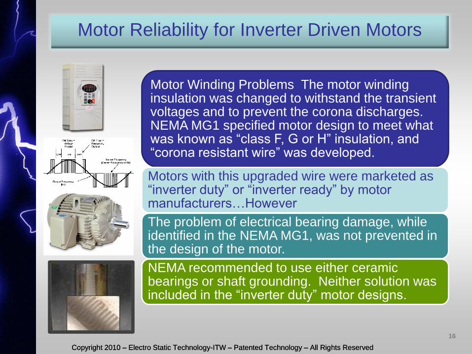
Motor Reliability for Inverter Driven Motors
Motor Winding Problems The motor winding insulation was changed to withstand the transient voltages and to prevent the corona discharges. NEMA MG1 specified motor design to meet what was known as “class F, G or H” insulation, and “corona resistant wire” was developed.
Motors with this upgraded wire were marketed as “inverter duty” or “inverter ready” by motor manufacturers…However
The problem of electrical bearing damage, while identified in the NEMA MG1, was not prevented in the design of the motor.
NEMA recommended to use either ceramic bearings or shaft grounding. Neither solution was included in the “inverter duty” motor designs.
Copyright 2010 – Electro Static Technology-ITW – Patented Technology – All Rights Reserved Copyright 2010 – Electro Static Technology-ITW – Patented Technology – All Rights Reserved
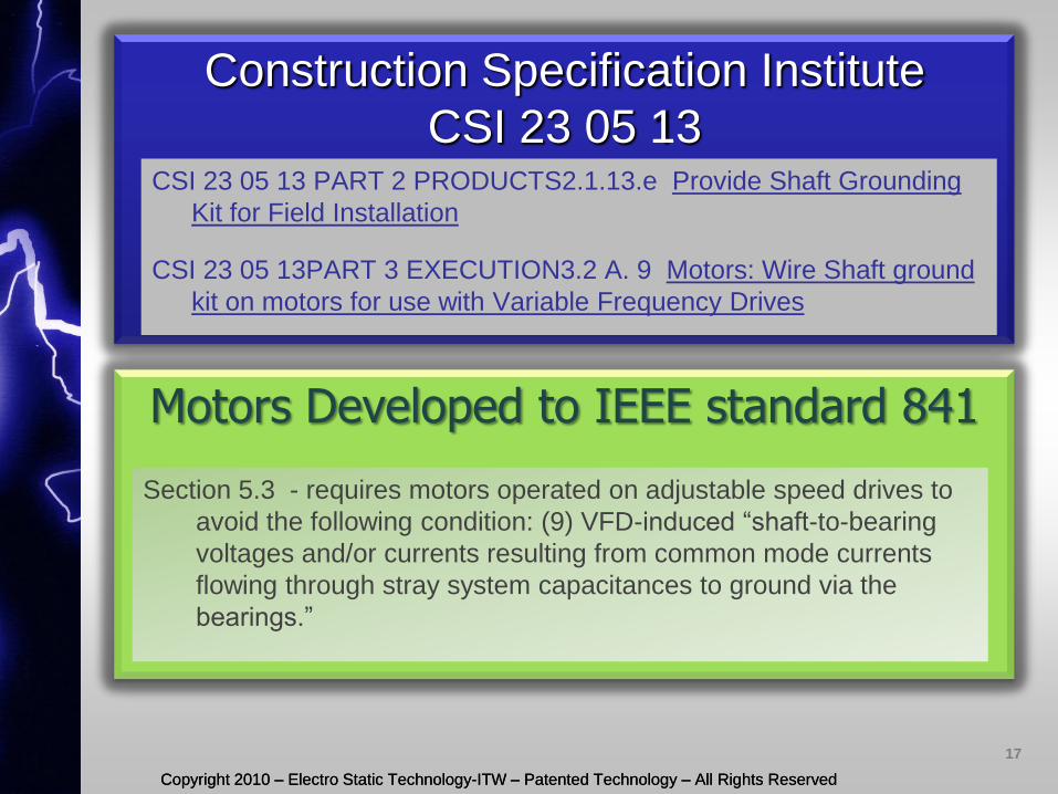
Construction Specification Institute
CSI 23 05 13 CSI 23 05 13 PART 2 PRODUCTS2.1.13.e Provide Shaft Grounding
Kit for Field Installation
CSI 23 05 13PART 3 EXECUTION3.2 A. 9 Motors: Wire Shaft ground
kit on motors for use with Variable Frequency Drives
Motors Developed to IEEE standard 841
Section 5.3 - requires motors operated on adjustable speed drives to
avoid the following condition: (9) VFD-induced “shaft-to-bearing
voltages and/or currents resulting from common mode currents
flowing through stray system capacitances to ground via the
bearings.”
17
Copyright 2010 – Electro Static Technology-ITW – Patented Technology – All Rights Reserved Copyright 2010 – Electro Static Technology-ITW – Patented Technology – All Rights Reserved
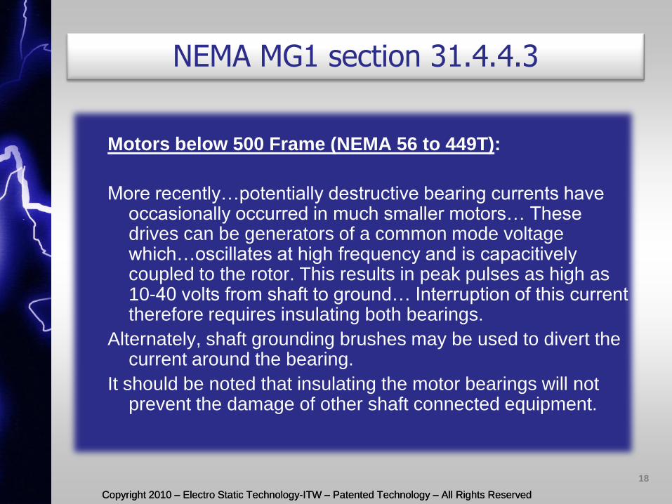
Motors below 500 Frame (NEMA 56 to 449T):
More recently…potentially destructive bearing currents have occasionally occurred in much smaller motors… These drives can be generators of a common mode voltage which…oscillates at high frequency and is capacitively coupled to the rotor. This results in peak pulses as high as 10-40 volts from shaft to ground… Interruption of this current therefore requires insulating both bearings.
Alternately, shaft grounding brushes may be used to divert the current around the bearing.
It should be noted that insulating the motor bearings will not prevent the damage of other shaft connected equipment.
NEMA MG1 section 31.4.4.3
18
Copyright 2010 – Electro Static Technology-ITW – Patented Technology – All Rights Reserved Copyright 2010 – Electro Static Technology-ITW – Patented Technology – All Rights Reserved
Stator
Rotor
Ground
VF
D D
rive
VFD Induced Voltages
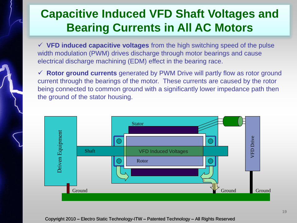
VFD induced capacitive voltages from the high switching speed of the pulse
width modulation (PWM) drives discharge through motor bearings and cause
electrical discharge machining (EDM) effect in the bearing race.
Rotor ground currents generated by PWM Drive will partly flow as rotor ground
current through the bearings of the motor. These currents are caused by the rotor
being connected to common ground with a significantly lower impedance path then
the ground of the stator housing.
Capacitive Induced VFD Shaft Voltages and
Bearing Currents in All AC Motors
Shaft
Ground Ground
19
Copyright 2010 – Electro Static Technology-ITW – Patented Technology – All Rights Reserved Copyright 2010 – Electro Static Technology-ITW – Patented Technology – All Rights Reserved
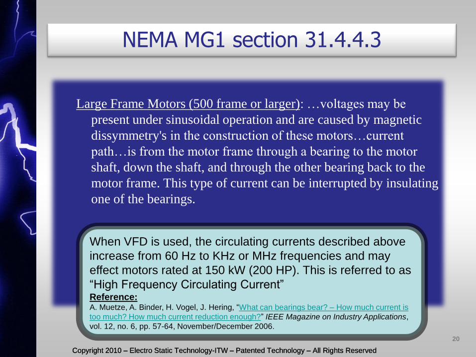
Large Frame Motors (500 frame or larger): …voltages may be
present under sinusoidal operation and are caused by magnetic
dissymmetry's in the construction of these motors…current
path…is from the motor frame through a bearing to the motor
shaft, down the shaft, and through the other bearing back to the
motor frame. This type of current can be interrupted by insulating
one of the bearings.
NEMA MG1 section 31.4.4.3
When VFD is used, the circulating currents described above
increase from 60 Hz to KHz or MHz frequencies and may
effect motors rated at 150 kW (200 HP). This is referred to as
“High Frequency Circulating Current” Reference: A. Muetze, A. Binder, H. Vogel, J. Hering, “What can bearings bear? – How much current is
too much? How much current reduction enough?” IEEE Magazine on Industry Applications,
vol. 12, no. 6, pp. 57-64, November/December 2006.
20
Copyright 2010 – Electro Static Technology-ITW – Patented Technology – All Rights Reserved Copyright 2010 – Electro Static Technology-ITW – Patented Technology – All Rights Reserved
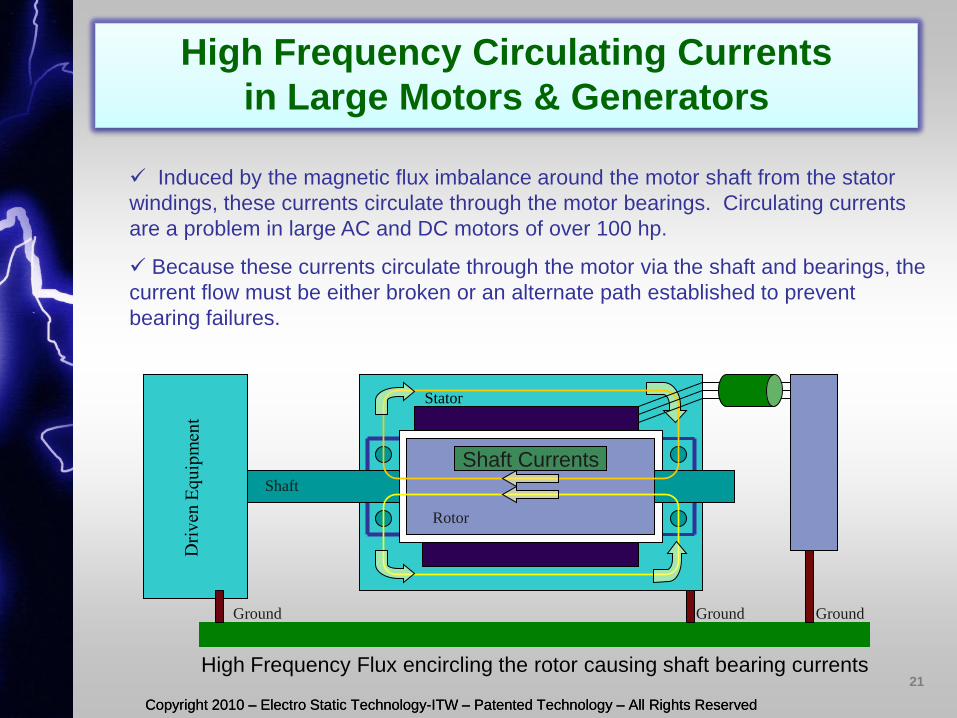
High Frequency Circulating Currents
in Large Motors & Generators
Stator
Rotor
Ground
Shaft Currents
Induced by the magnetic flux imbalance around the motor shaft from the stator
windings, these currents circulate through the motor bearings. Circulating currents
are a problem in large AC and DC motors of over 100 hp.
Because these currents circulate through the motor via the shaft and bearings, the
current flow must be either broken or an alternate path established to prevent
bearing failures.
Shaft
Ground Ground
High Frequency Flux encircling the rotor causing shaft bearing currents 21
Copyright 2010 – Electro Static Technology-ITW – Patented Technology – All Rights Reserved
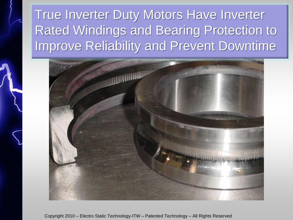
True Inverter Duty Motors Have Inverter
Rated Windings and Bearing Protection to
Improve Reliability and Prevent Downtime
Copyright 2010 – Electro Static Technology-ITW – Patented Technology – All Rights Reserved Copyright 2010 – Electro Static Technology-ITW – Patented Technology – All Rights Reserved
23
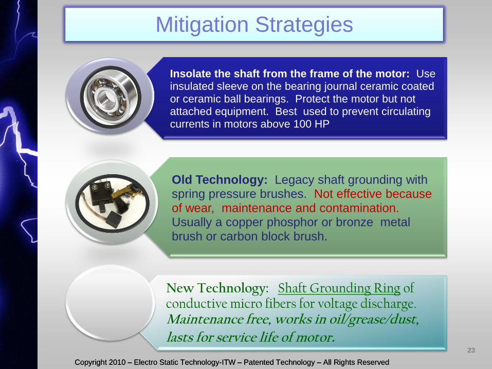
Insolate the shaft from the frame of the motor: Use insulated sleeve on the bearing journal ceramic coated or ceramic ball bearings. Protect the motor but not attached equipment. Best used to prevent circulating currents in motors above 100 HP
Old Technology: Legacy shaft grounding with spring pressure brushes. Not effective because of wear, maintenance and contamination. Usually a copper phosphor or bronze metal brush or carbon block brush.
New Technology: Shaft Grounding Ring of conductive micro fibers for voltage discharge. Maintenance free, works in oil/grease/dust,
lasts for service life of motor.
Mitigation Strategies
Copyright 2010 – Electro Static Technology-ITW – Patented Technology – All Rights Reserved Copyright 2010 – Electro Static Technology-ITW – Patented Technology – All Rights Reserved
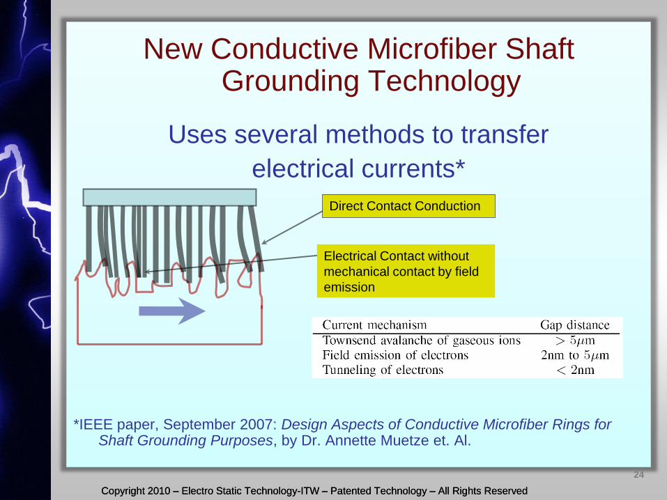
New Conductive Microfiber Shaft Grounding Technology
Uses several methods to transfer
electrical currents*
*IEEE paper, September 2007: Design Aspects of Conductive Microfiber Rings for
Shaft Grounding Purposes, by Dr. Annette Muetze et. Al.
Direct Contact Conduction
Electrical Contact without
mechanical contact by field
emission
24
Copyright 2010 – Electro Static Technology-ITW – Patented Technology – All Rights Reserved Copyright 2010 – Electro Static Technology-ITW – Patented Technology – All Rights Reserved
25
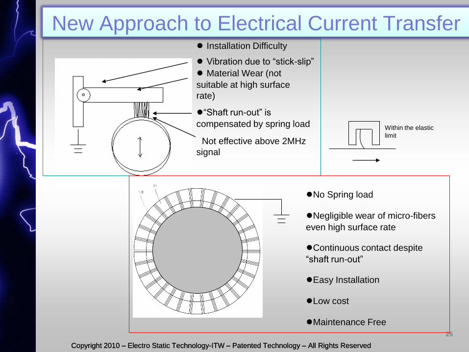
●“Shaft run-out” is
compensated by spring load
● Material Wear (not
suitable at high surface
rate)
● Vibration due to “stick-slip”
Not effective above 2MHz
signal
● Installation Difficulty
●No Spring load
●Negligible wear of micro-fibers
even high surface rate
●Continuous contact despite
“shaft run-out”
●Easy Installation
●Low cost
●Maintenance Free
Within the elastic
limit
New Approach to Electrical Current Transfer
Copyright 2010 – Electro Static Technology-ITW – Patented Technology – All Rights Reserved Copyright 2010 – Electro Static Technology-ITW – Patented Technology – All Rights Reserved
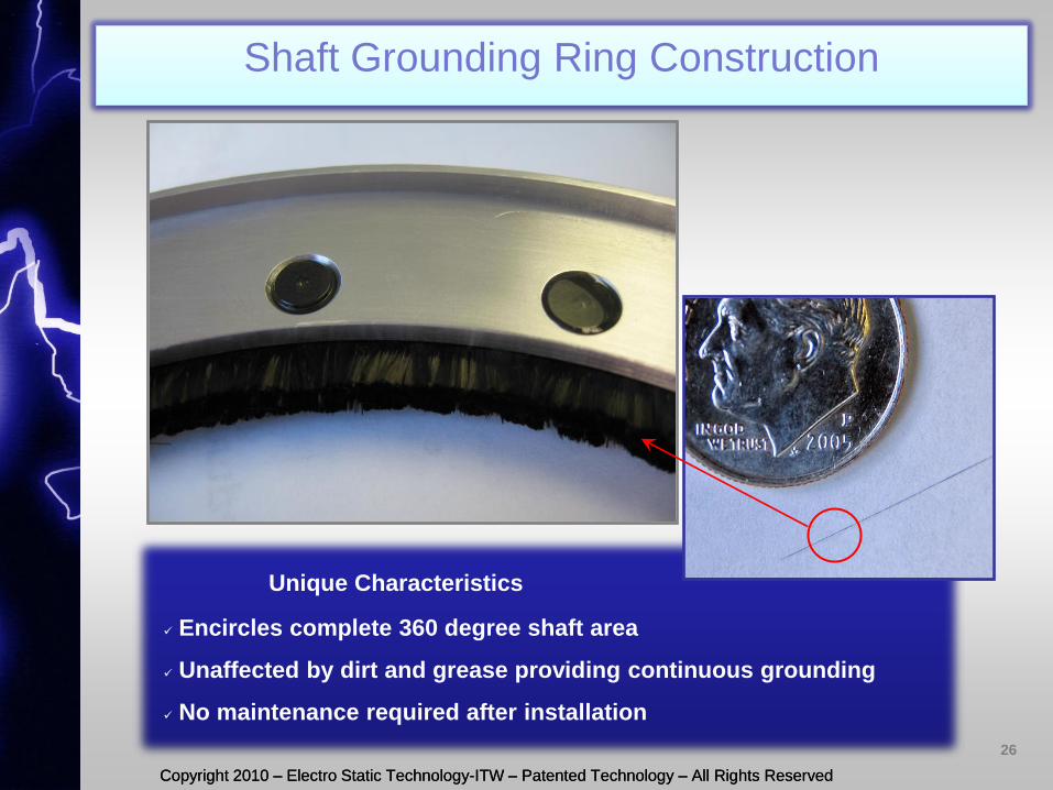
Unique Characteristics
Encircles complete 360 degree shaft area
Unaffected by dirt and grease providing continuous grounding
No maintenance required after installation
26
Shaft Grounding Ring Construction
Conductive
Micro Fibers
Copyright 2010 – Electro Static Technology-ITW – Patented Technology – All Rights Reserved Copyright 2010 – Electro Static Technology-ITW – Patented Technology – All Rights Reserved
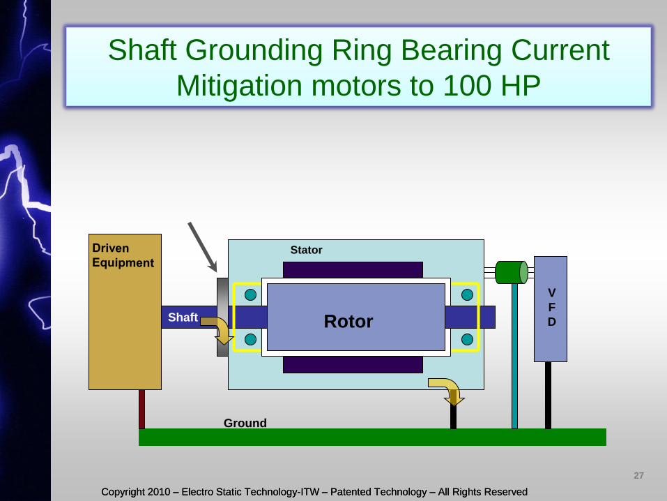
Shaft Grounding Ring Bearing Current
Mitigation motors to 100 HP
Stator
Rotor Shaft
V
F
D
Ground
27
Copyright 2010 – Electro Static Technology-ITW – Patented Technology – All Rights Reserved Copyright 2010 – Electro Static Technology-ITW – Patented Technology – All Rights Reserved
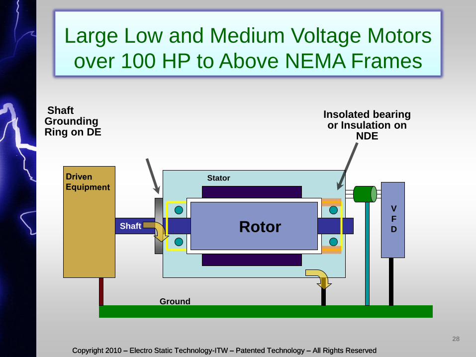
Large Low and Medium Voltage Motors
over 100 HP to Above NEMA Frames
Stator
Rotor Shaft
Ground
V
F
D
Insolated bearing or Insulation on
NDE
Shaft Grounding Ring on DE
28
Copyright 2010 – Electro Static Technology-ITW – Patented Technology – All Rights Reserved Copyright 2010 – Electro Static Technology-ITW – Patented Technology – All Rights Reserved
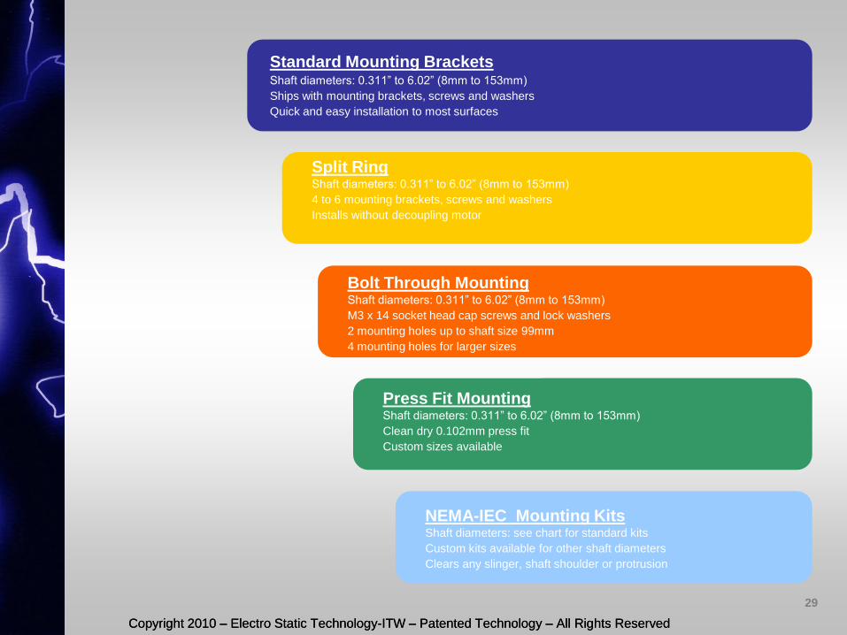
Standard Mounting Brackets Shaft diameters: 0.311” to 6.02” (8mm to 153mm)
Ships with mounting brackets, screws and washers
Quick and easy installation to most surfaces
Bolt Through Mounting Shaft diameters: 0.311” to 6.02” (8mm to 153mm)
M3 x 14 socket head cap screws and lock washers
2 mounting holes up to shaft size 99mm
4 mounting holes for larger sizes
Press Fit Mounting Shaft diameters: 0.311” to 6.02” (8mm to 153mm)
Clean dry 0.102mm press fit
Custom sizes available
Split Ring Shaft diameters: 0.311” to 6.02” (8mm to 153mm)
4 to 6 mounting brackets, screws and washers
Installs without decoupling motor
NEMA-IEC Mounting Kits Shaft diameters: see chart for standard kits
Custom kits available for other shaft diameters
Clears any slinger, shaft shoulder or protrusion
29
Copyright 2010 – Electro Static Technology-ITW – Patented Technology – All Rights Reserved Copyright 2010 – Electro Static Technology-ITW – Patented Technology – All Rights Reserved
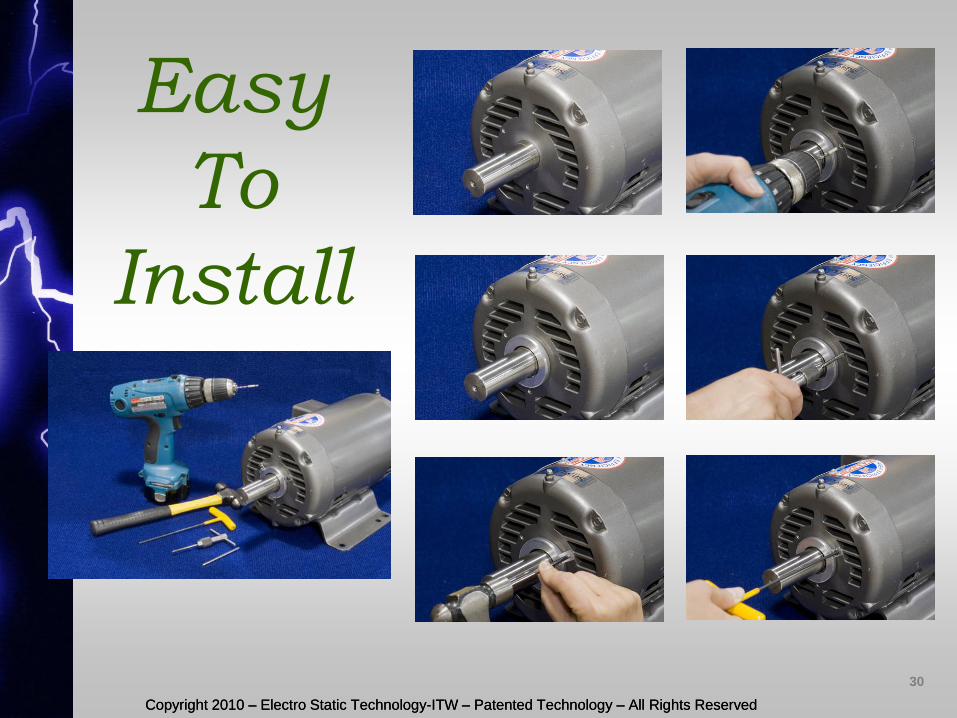
Easy
To
Install
30
Copyright 2010 – Electro Static Technology-ITW – Patented Technology – All Rights Reserved Copyright 2010 – Electro Static Technology-ITW – Patented Technology – All Rights Reserved
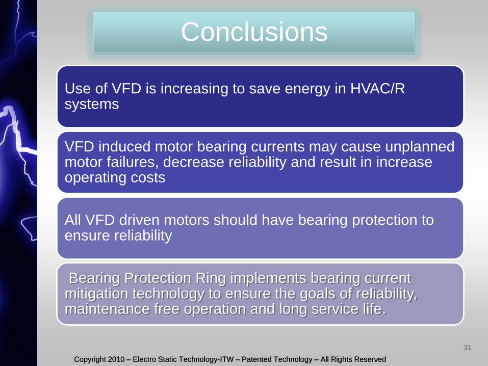
Conclusions
Use of VFD is increasing to save energy in HVAC/R systems
VFD induced motor bearing currents may cause unplanned motor failures, decrease reliability and result in increase operating costs
All VFD driven motors should have bearing protection to ensure reliability
Bearing Protection Ring implements bearing current mitigation technology to ensure the goals of reliability, maintenance free operation and long service life.
31