PROSTHODONTICS ( REMOVABLE PARTIAL DENTURES ) 2015 2016
143
PROSTHODONTICS (REMOVABLE PARTIAL DENTURES) Dr. Azad Almuthaffer B.D.S., M.Sc. prosth . Babylon university College of dentistry Prosthodontic department Third class THIRD EDITION 2015-2016 You can download these lectures from (moodle) electronic- learning platform: Or from this link: www.uobabylon.edu.iq/uobcoleges/default.aspx?fid=4 E-mail of lecturer: [email protected]
-
Upload
ddert -
Category
Health & Medicine
-
view
6.760 -
download
261
Transcript of PROSTHODONTICS ( REMOVABLE PARTIAL DENTURES ) 2015 2016
PROSTHODONTICS (REMOVABLE
PARTIAL DENTURES)
Dr. Azad Almuthaffer
B.D.S., M.Sc. prosth.
Babylon university
College of dentistry
Prosthodontic
department
Third class
THIRD EDITION 2015-2016
You can download these lectures from (moodle) electronic-
learning platform:
Or from this link:
www.uobabylon.edu.iq/uobcoleges/default.aspx?fid=4
E-mail of lecturer: [email protected]
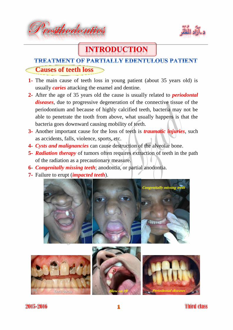
Causes of teeth loss
The main cause of teeth loss in young patient (about 35 years old) is 1-
usually caries attacking the enamel and dentine.
After the age of 35 years old the cause is usually related to periodontal 2-
diseases, due to progressive degeneration of the connective tissue of the
periodontium and because of highly calcified teeth, bacteria may not be
able to penetrate the tooth from above, what usually happens is that the
bacteria goes downward causing mobility of teeth.
Another important cause for the loss of teeth is traumatic injuries, such 3-
as accidents, falls, violence, sports, etc.
Cysts and malignancies can cause destruction of the alveolar bone. 4-
Radiation therapy of tumors often requires extraction of teeth in the path 5-
of the radiation as a precautionary measure.
Congenitally missing teeth; anodontia, or partial anodontia. 6-
Failure to erupt (impacted teeth). 7-
Congenitally missing teeth
Blow on #9 Periodontal diseases
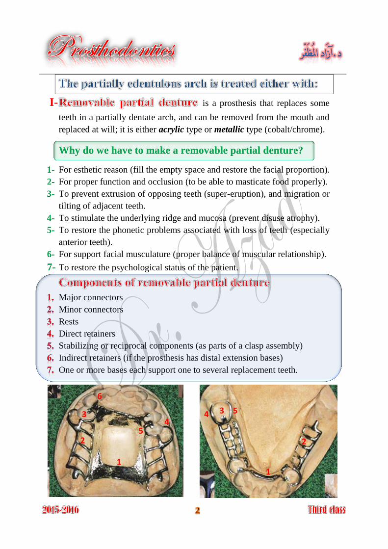
I- is a prosthesis that replaces some
teeth in a partially dentate arch, and can be removed from the mouth and
replaced at will; it is either acrylic type or metallic type (cobalt/chrome).
Why do we have to make a removable partial denture?
For esthetic reason (fill the empty space and restore the facial proportion). 1-
For proper function and occlusion (to be able to masticate food properly). 2-
To prevent extrusion of opposing teeth (super-eruption), and migration or 3-
tilting of adjacent teeth.
To stimulate the underlying ridge and mucosa (prevent disuse atrophy). 4-
To restore the phonetic problems associated with loss of teeth (especially 5-
anterior teeth).
For support facial musculature (proper balance of muscular relationship). 6-
To restore the psychological status of the patient.7-
Major connectors
Minor connectors
Rests
Direct retainers
Stabilizing or reciprocal components (as parts of a clasp assembly)
Indirect retainers (if the prosthesis has distal extension bases)
One or more bases each support one to several replacement teeth.
1 1
2 2
3 3 4
4 5
5
6
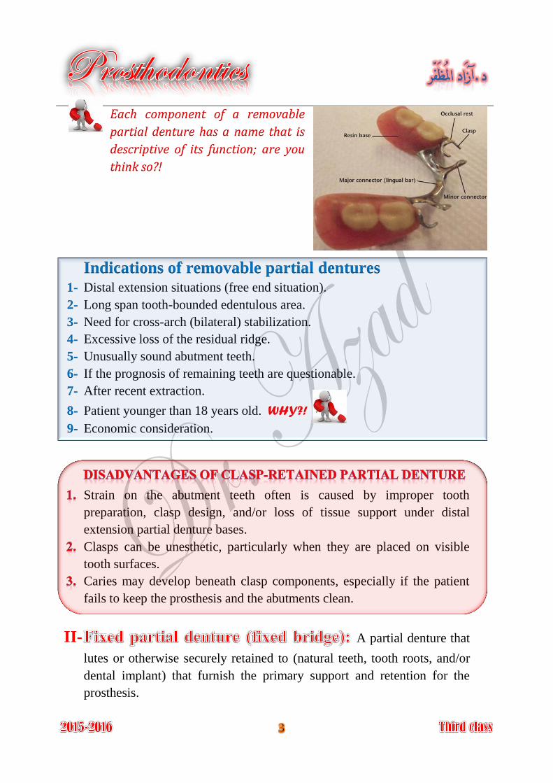
Each component of a removable
partial denture has a name that is
descriptive of its function; are you
think so?!
Indications of removable partial dentures Distal extension situations (free end situation). 1-
Long span tooth-bounded edentulous area. 2-
Need for cross-arch (bilateral) stabilization. 3-
Excessive loss of the residual ridge. 4-
Unusually sound abutment teeth. 5-
If the prognosis of remaining teeth are questionable. 6-
After recent extraction. 7-
Patient younger than 18 years old. WHY?! 8-
Economic consideration. 9-
Strain on the abutment teeth often is caused by improper tooth
preparation, clasp design, and/or loss of tissue support under distal
extension partial denture bases.
Clasps can be unesthetic, particularly when they are placed on visible
tooth surfaces.
Caries may develop beneath clasp components, especially if the patient
fails to keep the prosthesis and the abutments clean.
II- A partial denture that
lutes or otherwise securely retained to (natural teeth, tooth roots, and/or
dental implant) that furnish the primary support and retention for the
prosthesis.
Indications of fixed partial denture
Unilateral bounded edentulous short span. 1-
Class IV Kennedy with normal loss of bone. 2-
Modification area located anteriorly with class I and class II Kennedy 3-
classification for simplify the design of removable partial denture.
The dental implants are considered adjuncts in fixed and removable
therapy. However, not all patients are candidates for dental implant
therapy.
Unfavorable regional anatomy. 1-
Uncontrolled systemic disease. 2-
Extreme surgical risk. 3-
High-dose head and neck radiation. 4-
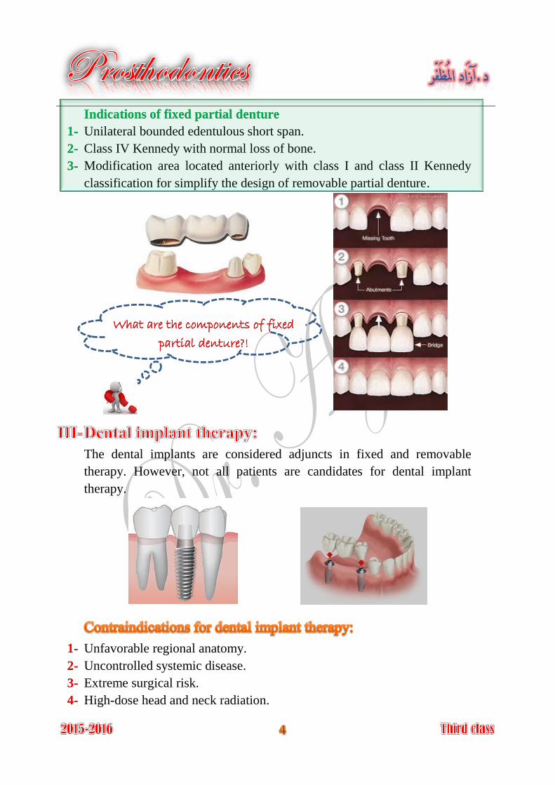
What are the components of fixed
partial denture?!
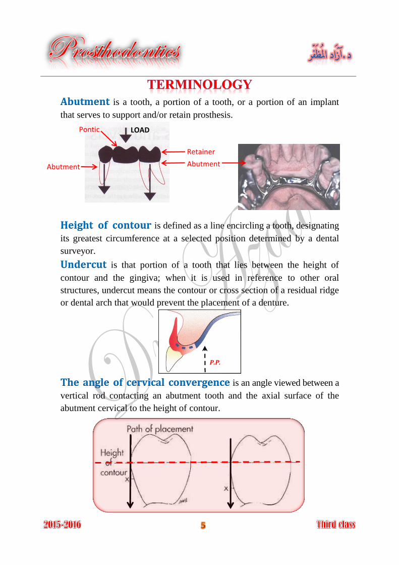
is a tooth, a portion of a tooth, or a portion of an implant Abutmentthat serves to support and/or retain prosthesis.
Height of contour is defined as a line encircling a tooth, designating
its greatest circumference at a selected position determined by a dental
surveyor.
is that portion of a tooth that lies between the height of Undercutcontour and the gingiva; when it is used in reference to other oral
structures, undercut means the contour or cross section of a residual ridge
or dental arch that would prevent the placement of a denture.
The angle of cervical convergence is an angle viewed between a
vertical rod contacting an abutment tooth and the axial surface of the
abutment cervical to the height of contour.
Abutment Abutment
Retainer
Pontic LOAD
P.P.
Guiding planes are two or more vertically parallel surfaces of
abutment teeth shaped to direct prosthesis during insertion and removal.
is a unilateral removable partial denture design. Nesbitt denture
is the specific direction Path of insertion (path of placement)in which prosthesis is placed on the abutment teeth.
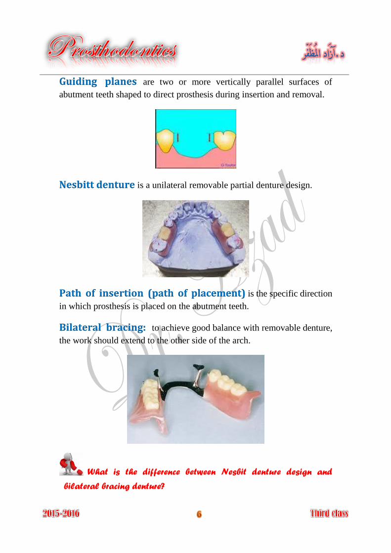
Bilateral bracing: to achieve good balance with removable denture,
the work should extend to the other side of the arch.
What is the difference between Nesbit denture design and
bilateral bracing denture?
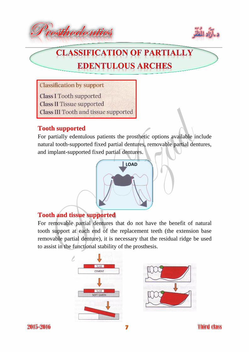
Tooth supported
For partially edentulous patients the prosthetic options available include
natural tooth-supported fixed partial dentures, removable partial dentures,
and implant-supported fixed partial dentures.
Tooth and tissue supported
For removable partial dentures that do not have the benefit of natural
tooth support at each end of the replacement teeth (the extension base
removable partial denture), it is necessary that the residual ridge be used
to assist in the functional stability of the prosthesis.
LOAD
where we have two abutment teeth on either side of Bounded saddle:
the edentulous space, treated by either fixed or removable partial denture.
where there is only on abutment tooth at an end Free-ended saddle:
of the edentulous space, treated is only by a removable partial denture.
The Kennedy method of classification was originally proposed by
Dr. Edward Kennedy in 1925.
The Kennedy classification system is composed of four major categories
denoted Class I through Class IV. The numeric sequence of the
classification system was based on the frequency of occurrence, with
Class I arches being most common and Class IV arches least common.
Bilateral edentulous areas located posterior to the natural teeth. Class I:
Unilateral edentulous area located posterior to the remaining Class II:
natural teeth.
Unilateral edentulous area with natural teeth remaining both Class III:
anterior and posterior to it.
Single, but bilateral (crossing the midline), edentulous area Class IV:
located anterior to the remaining natural teeth.
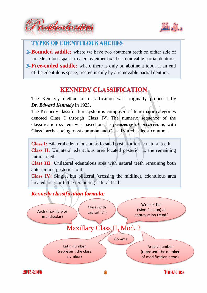
Kennedy classification formula:
Maxillary Class II, Mod. 2
Arch (maxillary or mandibular)
Class (with capital "C")
Latin number (represent the class
number)
Write either (Modification) or
abbreviation (Mod.)
Arabic number (represent the number of modification areas)
Comma
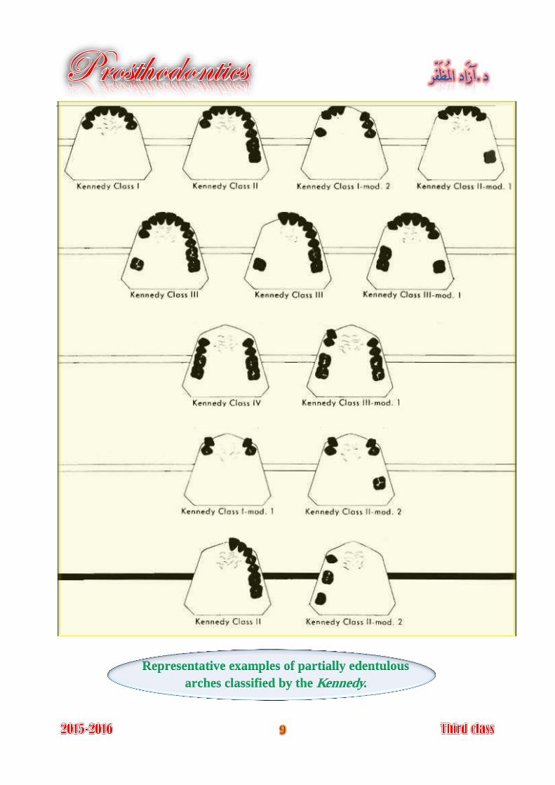
Representative examples of partially edentulous
arches classified by the Kennedy.
APPLEGATE'S RULES FOR APPLYING THE KENNEDY
CLASSIFICATION
(Rules governing the application of the Kennedy method by Dr. O.C. Applegate 1954)
Rule 1
Classification should follow rather than precede any extractions of teeth
that might alter the original classification.
Rule 2
If a third molar is missing and not to be replaced, it is not considered in
the classification.
Rule 3
If a third molar is present and is to be used as an abutment, it is
considered in the classification.
Rule 4
If a second molar is missing and is not to be replaced, it is not considered
in the classification (e.g. if the opposing second molar is likewise missing
and is not to be replaced).
Rule 5
The most posterior edentulous area (or areas) always determines the
classification.
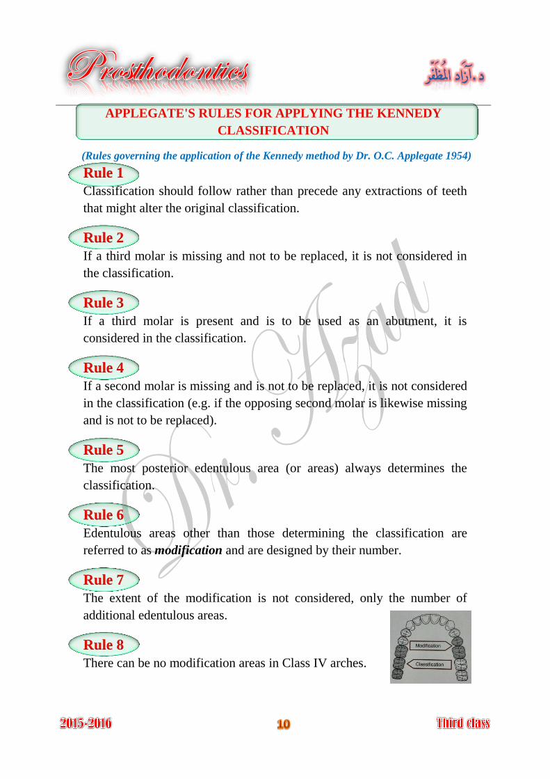
Rule 6
Edentulous areas other than those determining the classification are
referred to as modification and are designed by their number.
Rule 7
The extent of the modification is not considered, only the number of
additional edentulous areas.
Rule 8
There can be no modification areas in Class IV arches.
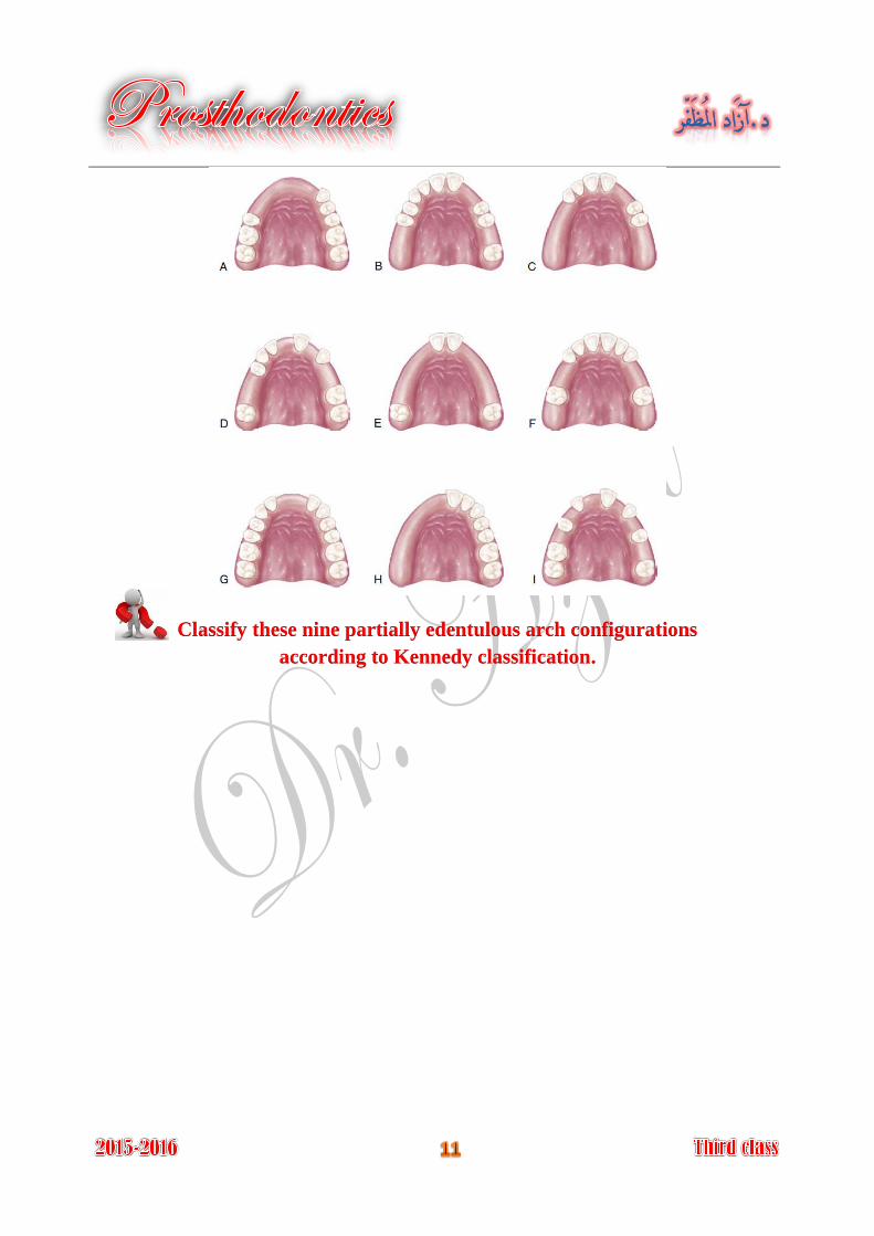
Classify these nine partially edentulous arch configurations
according to Kennedy classification.
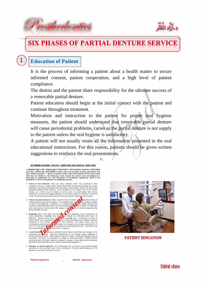
Education of Patient
It is the process of informing a patient about a health matter to secure
informed consent, patient cooperation, and a high level of patient
compliance.
The dentist and the patient share responsibility for the ultimate success of
a removable partial denture.
Patient education should begin at the initial contact with the patient and
continue throughout treatment.
Motivation and instruction to the patient for proper oral hygiene
measures, the patient should understand that removable partial denture
will cause periodontal problems, caries so the partial denture is not supply
to the patient unless the oral hygiene is satisfactory.
A patient will not usually retain all the information presented in the oral
educational instructions. For this reason, patients should be given written
suggestions to reinforce the oral presentations.
1
Patient signature dentist signature
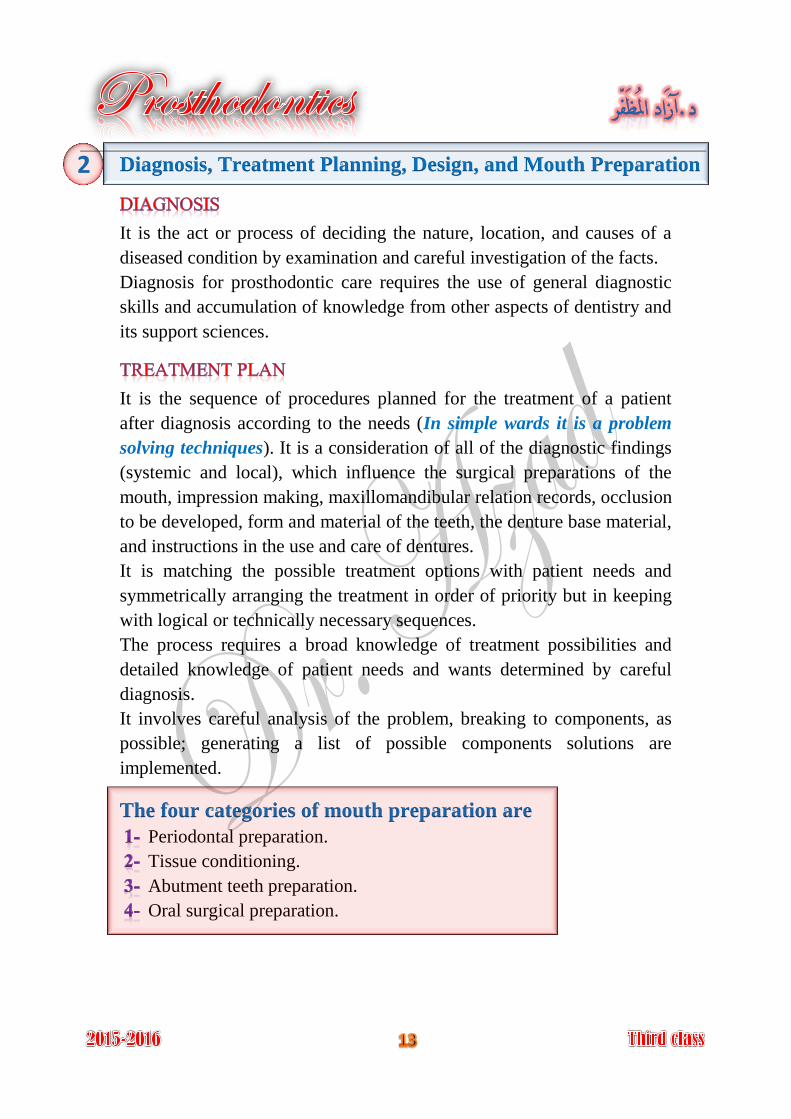
Diagnosis, Treatment Planning, Design, and Mouth Preparation
It is the act or process of deciding the nature, location, and causes of a
diseased condition by examination and careful investigation of the facts.
Diagnosis for prosthodontic care requires the use of general diagnostic
skills and accumulation of knowledge from other aspects of dentistry and
its support sciences.
It is the sequence of procedures planned for the treatment of a patient
after diagnosis according to the needs (In simple wards it is a problem
solving techniques). It is a consideration of all of the diagnostic findings
(systemic and local), which influence the surgical preparations of the
mouth, impression making, maxillomandibular relation records, occlusion
to be developed, form and material of the teeth, the denture base material,
and instructions in the use and care of dentures.
It is matching the possible treatment options with patient needs and
symmetrically arranging the treatment in order of priority but in keeping
with logical or technically necessary sequences.
The process requires a broad knowledge of treatment possibilities and
detailed knowledge of patient needs and wants determined by careful
diagnosis.
It involves careful analysis of the problem, breaking to components, as
possible; generating a list of possible components solutions are
implemented.
The four categories of mouth preparation are
Periodontal preparation.
Tissue conditioning.
Abutment teeth preparation.
Oral surgical preparation.
2
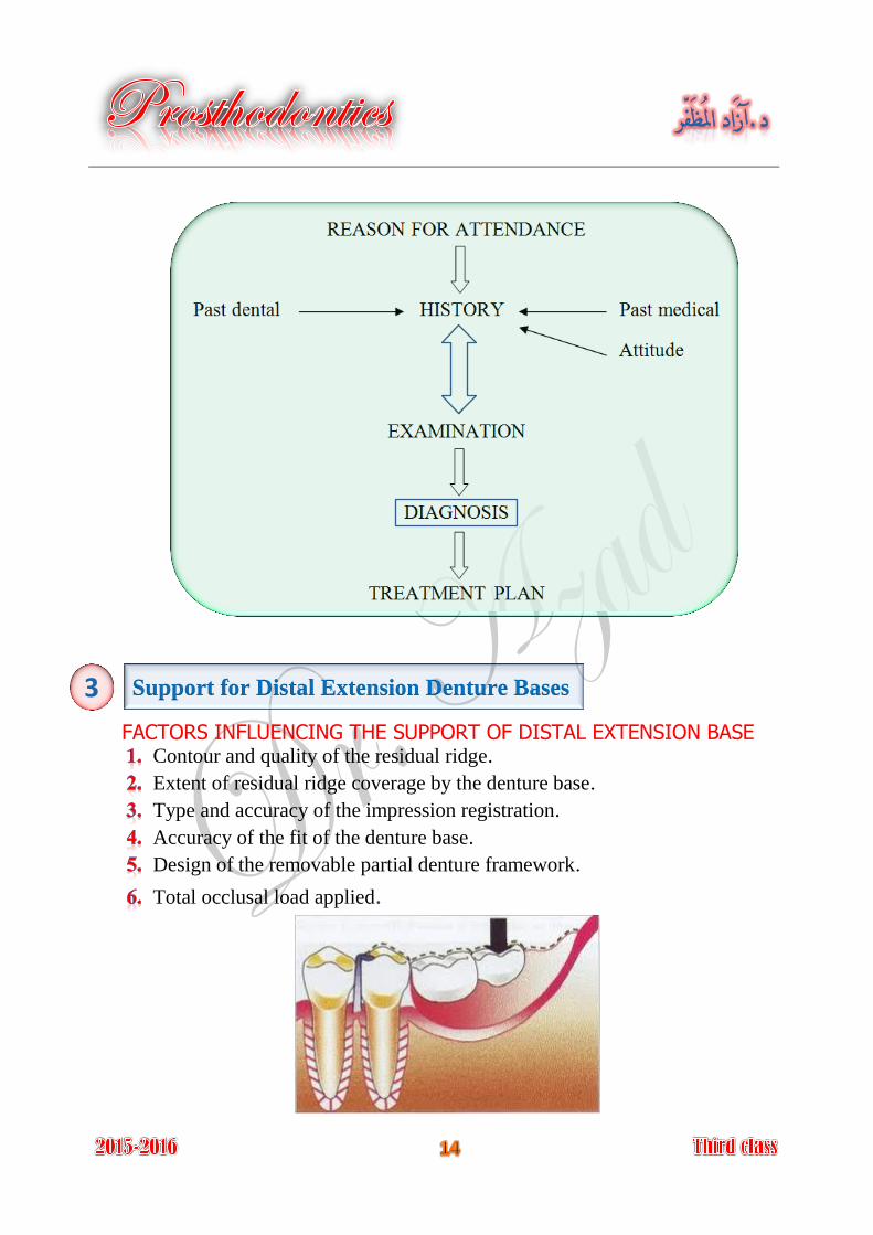
Support for Distal Extension Denture Bases
FACTORS INFLUENCING THE SUPPORT OF DISTAL EXTENSION BASE Contour and quality of the residual ridge.
Extent of residual ridge coverage by the denture base.
Type and accuracy of the impression registration.
Accuracy of the fit of the denture base.
Design of the removable partial denture framework.
Total occlusal load applied.
3
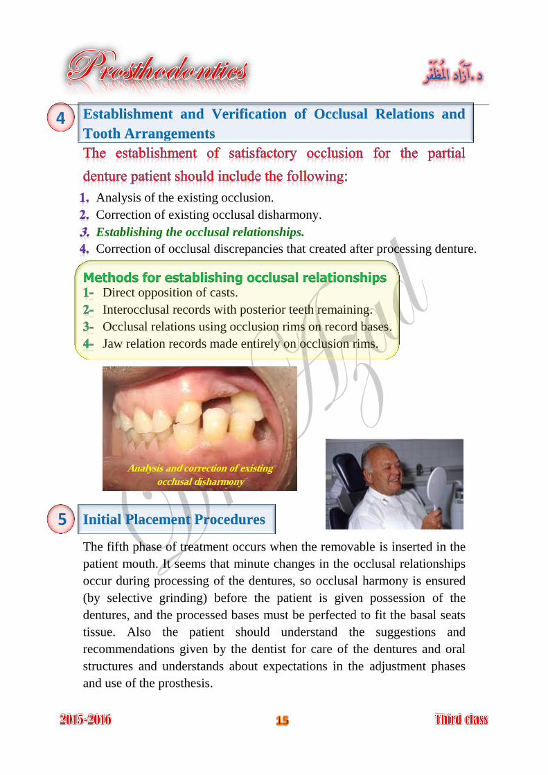
Establishment and Verification of Occlusal Relations and
Tooth Arrangements
Analysis of the existing occlusion.
Correction of existing occlusal disharmony.
Establishing the occlusal relationships.
Correction of occlusal discrepancies that created after processing denture.
Methods for establishing occlusal relationships Direct opposition of casts.
Interocclusal records with posterior teeth remaining.
Occlusal relations using occlusion rims on record bases.
Jaw relation records made entirely on occlusion rims.
Initial Placement Procedures
The fifth phase of treatment occurs when the removable is inserted in the
patient mouth. It seems that minute changes in the occlusal relationships
occur during processing of the dentures, so occlusal harmony is ensured
(by selective grinding) before the patient is given possession of the
dentures, and the processed bases must be perfected to fit the basal seats
tissue. Also the patient should understand the suggestions and
recommendations given by the dentist for care of the dentures and oral
structures and understands about expectations in the adjustment phases
and use of the prosthesis.
5
4
Analysis and correction of existing
occlusal disharmony
Periodic Recall
Periodic reevaluation of the patient is critical for early recognition of
changes in the oral structures to allow steps to be taken to maintain oral
health.
These examinations must monitor:
The condition of the oral tissue. 1-
The response to the prosthesis. 2-
The patient's acceptance. 3-
The patient's commitment to maintain oral hygiene. 4-
Although a 6-month recall period is adequate for most patients, a more
frequent evaluation may be required for some.
6
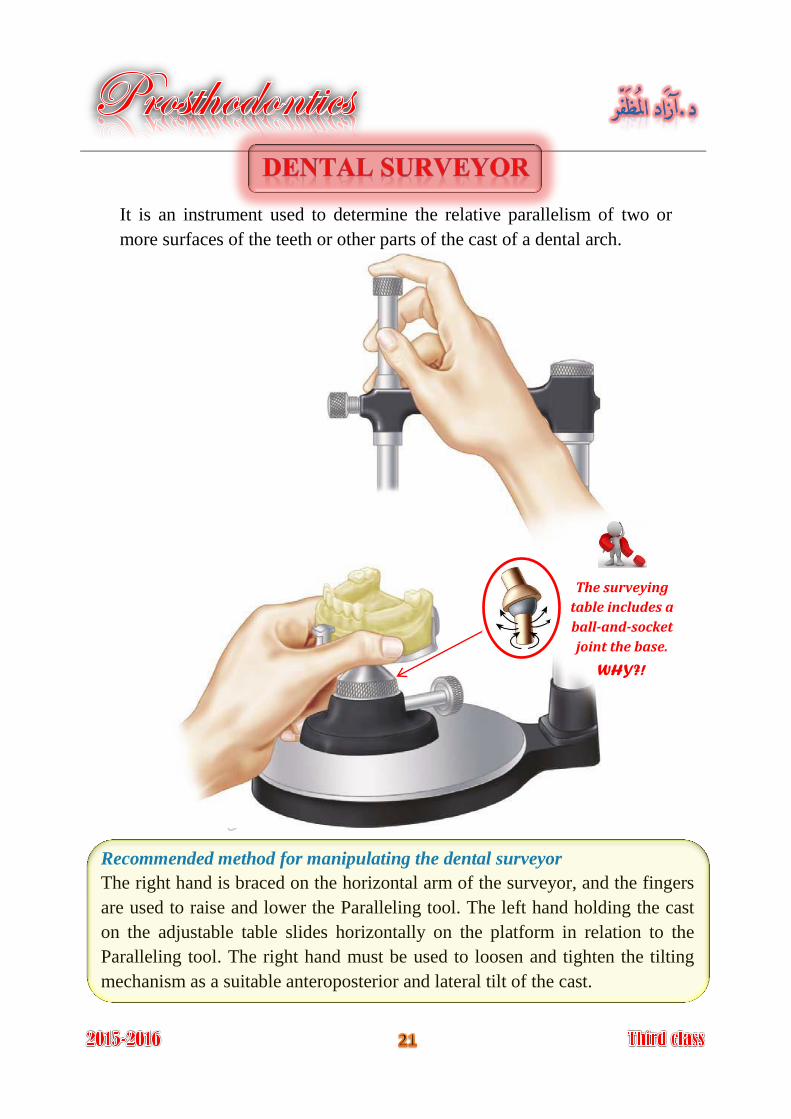
It is an instrument used to determine the relative parallelism of two or
more surfaces of the teeth or other parts of the cast of a dental arch.
Recommended method for manipulating the dental surveyor
The right hand is braced on the horizontal arm of the surveyor, and the fingers
are used to raise and lower the Paralleling tool. The left hand holding the cast
on the adjustable table slides horizontally on the platform in relation to the
Paralleling tool. The right hand must be used to loosen and tighten the tilting
mechanism as a suitable anteroposterior and lateral tilt of the cast.
The surveying
table includes a
ball-and-socket
joint the base.
WHY?!
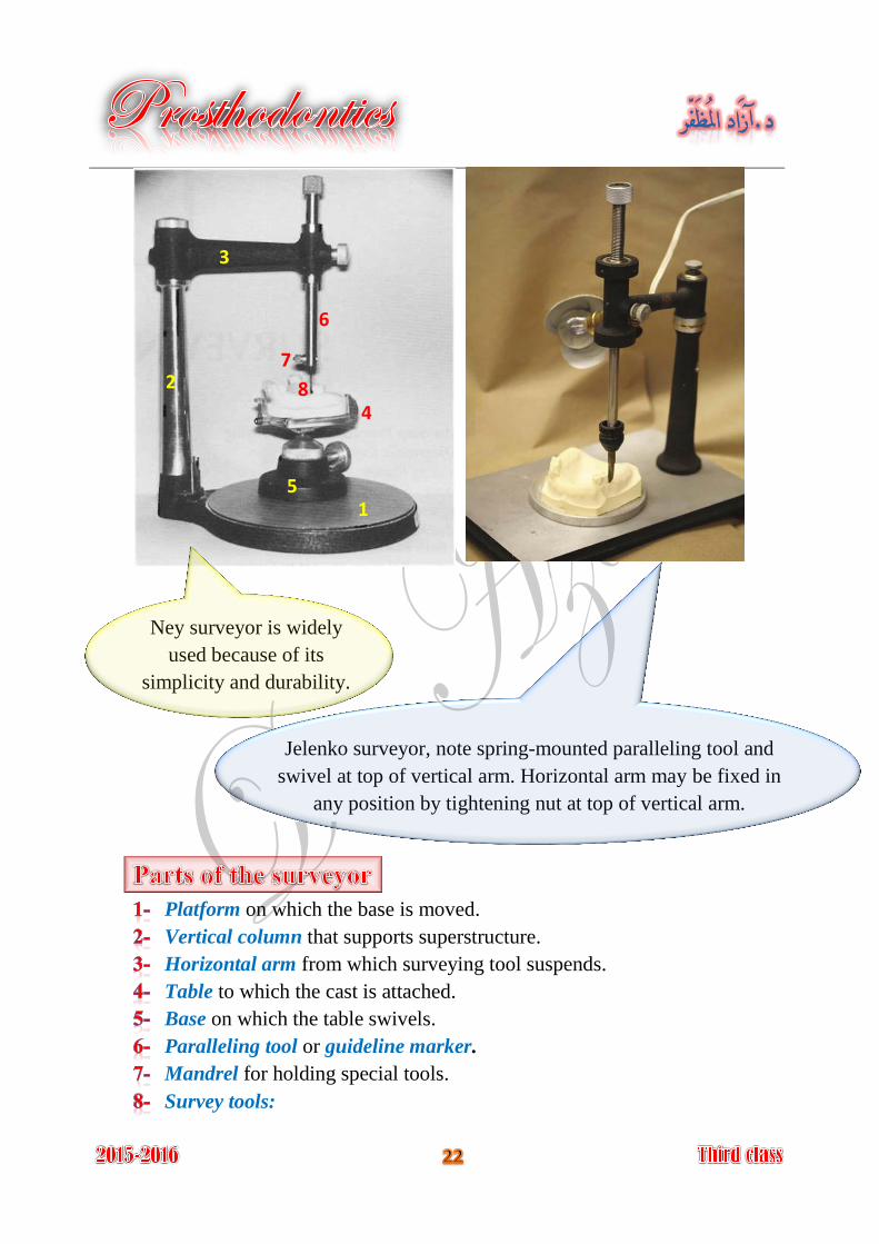
Platform on which the base is moved.
Vertical column that supports superstructure.
Horizontal arm from which surveying tool suspends.
Table to which the cast is attached.
Base on which the table swivels.
Paralleling tool or guideline marker.
Mandrel for holding special tools.
Survey tools:
Ney surveyor is widely
used because of its
simplicity and durability.
Jelenko surveyor, note spring-mounted paralleling tool and
swivel at top of vertical arm. Horizontal arm may be fixed in
any position by tightening nut at top of vertical arm.
1
2
3
4
5
6
7
8
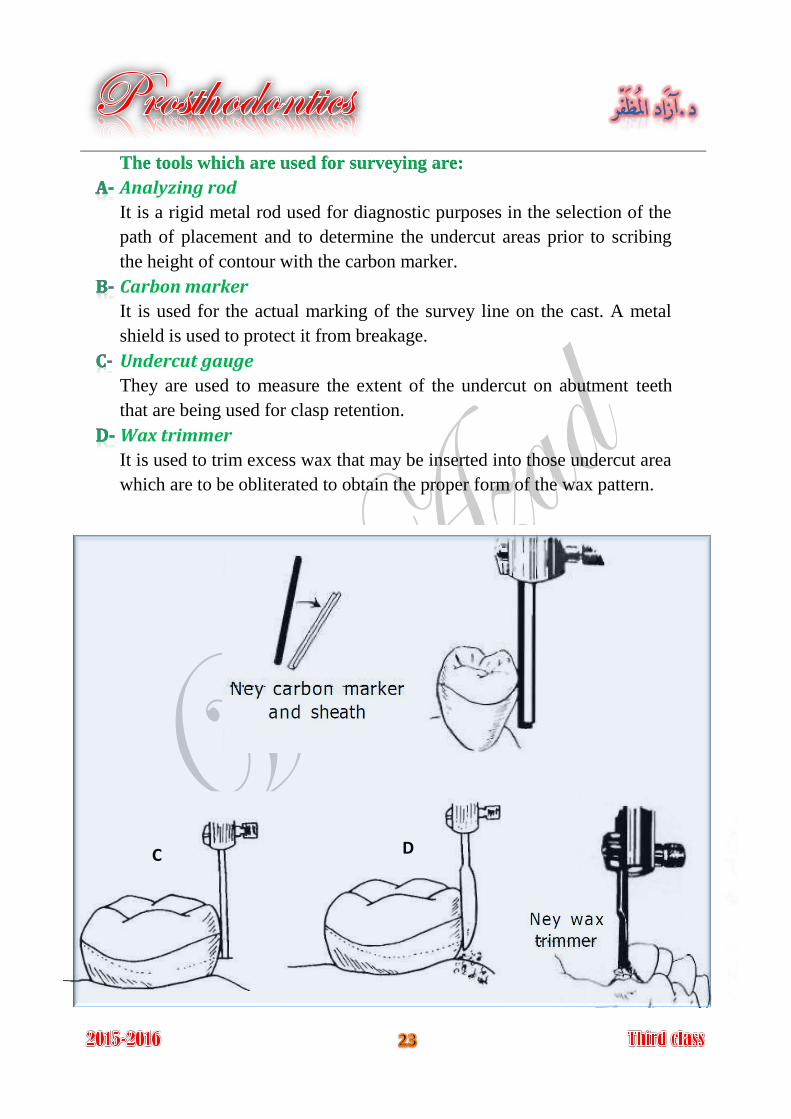
The tools which are used for surveying are:
Analyzing rod
It is a rigid metal rod used for diagnostic purposes in the selection of the
path of placement and to determine the undercut areas prior to scribing
the height of contour with the carbon marker.
Carbon marker
It is used for the actual marking of the survey line on the cast. A metal
shield is used to protect it from breakage.
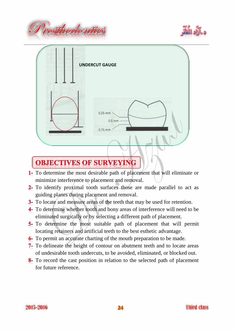
Undercut gauge
They are used to measure the extent of the undercut on abutment teeth
that are being used for clasp retention.
Wax trimmer
It is used to trim excess wax that may be inserted into those undercut area
which are to be obliterated to obtain the proper form of the wax pattern.
C D
To determine the most desirable path of placement that will eliminate or
minimize interference to placement and removal.
To identify proximal tooth surfaces those are made parallel to act as
guiding planes during placement and removal.
To locate and measure areas of the teeth that may be used for retention.
To determine whether tooth and bony areas of interference will need to be
eliminated surgically or by selecting a different path of placement.
To determine the most suitable path of placement that will permit
locating retainers and artificial teeth to the best esthetic advantage.
To permit an accurate charting of the mouth preparation to be made.
To delineate the height of contour on abutment teeth and to locate areas
of undesirable tooth undercuts, to be avoided, eliminated, or blocked out.
To record the cast position in relation to the selected path of placement
for future reference.
UNDERCUT GAUGE
Surveying a tooth consisted of locating accurately the height of its
maximum contour in relation to the plane in which the cast is positioned.
Whenever possible, cast should be surveyed with the occlusal plane
parallel to the base of the surveyor so that the path of insertion is vertical
to the occlusal plane.
The fact that the majority of the natural teeth crowns are bulbous in shape
(have a suprabulge area); this suprabulge point could occur anywhere
between the occlusal surface and the gingival margin. When a vertical
arm is brought into contact with the convex surface, they will contact
only at one point that is the point of maximum convexity. When this
surface is rotated, and is still in contact with the vertical arm, an
imaginary line will be traced at the greatest circumference, when we
substituted this vertical analyzing rod with a carbon marker then an
actual line will be produced at the level of the maximum tooth bulge, this
line is called survey line.
The area of a tooth occlusal to the survey line is a non-undercut area,
while the area gingival to the survey line is undercut area. When a tooth
is tilted or rotated in relation to the analyzing rod, another survey line will
be traced, as result, the extent of non-undercut area and the undercut area
are consequently changed. That means that the survey line can vary
according to the angle formed by contact of the vertical analyzing rod
with the tooth surface. Alteration of undercut area can be done by anterior
and posterior tilting of dental cast.
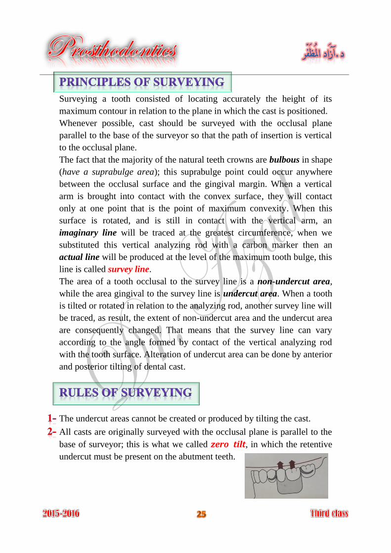
The undercut areas cannot be created or produced by tilting the cast.
All casts are originally surveyed with the occlusal plane is parallel to the
base of surveyor; this is what we called zero tilt, in which the retentive
undercut must be present on the abutment teeth.
Most patients will tend to seat the partial denture under force of
occlusion. If the path of insertion is other than vertical to the occlusal
plane such seating may deform the clasps. Also dislodging forces are
always directed perpendicular to the occlusal plane.
The retentive tip of the clasp must engage the undercut area, which are
present when the cast is surveyed in certain position.
Wherever possible, the undesirable undercut and area of interference are
removed during mouth preparation by recontouring teeth or making
necessary restoration.
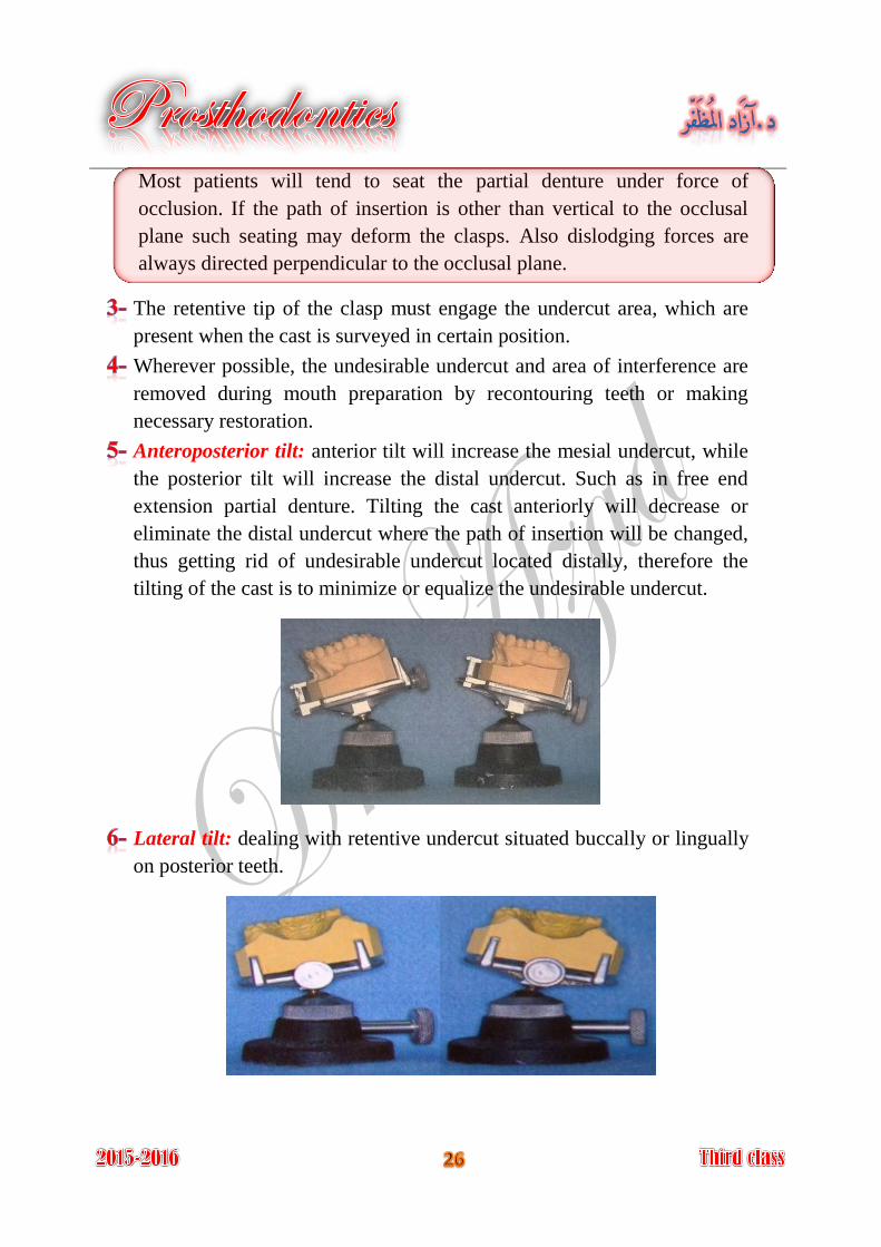
Anteroposterior tilt: anterior tilt will increase the mesial undercut, while
the posterior tilt will increase the distal undercut. Such as in free end
extension partial denture. Tilting the cast anteriorly will decrease or
eliminate the distal undercut where the path of insertion will be changed,
thus getting rid of undesirable undercut located distally, therefore the
tilting of the cast is to minimize or equalize the undesirable undercut.
Lateral tilt: dealing with retentive undercut situated buccally or lingually
on posterior teeth.
A partial denture should have a single path of insertion, this is only
possible for dentures with bounded saddle, for dentures with free end
saddles two or more paths of insertion will be possible.
The effect of tilting a cast on the surveyor will be:
Redistribution of undercuts to the desired areas. 1-
Allow more favorable path of insertion. 2-
Allow the use of a desired type of clasp for better function and esthetic. 3-
Allow the use of a design to minimize food impaction, food 4-
entrapment and plaque accumulation.
Types of undercuts established by surveyor
Contour: due to natural contour of the tooth.
Positional: due to tilting of cast on surveyor.
used for retaining the removable partial denture Desirable undercut:
against dislodging forces by incorporating retentive flexible clasp arm.
undercuts other than those used for retention Undesirable undercut:
are considered undesirable and should be eliminated by:
Tooth recontouring.
Placing properly contoured crown restoration on the tooth.
Tilting the cast and change the path of insertion.
Blocking out the undercut with wax on the master cast.
(Identify the most favorable tilt)
1- Guiding Planes
Guiding planes are parallel surfaces of abutment teeth that direct the
insertion and removal of a partial denture. The path of insertion should be
parallel to the guiding planes. Proximal tooth surfaces that bear a parallel
relationship to one another must either be found or be created to act as
guiding planes.
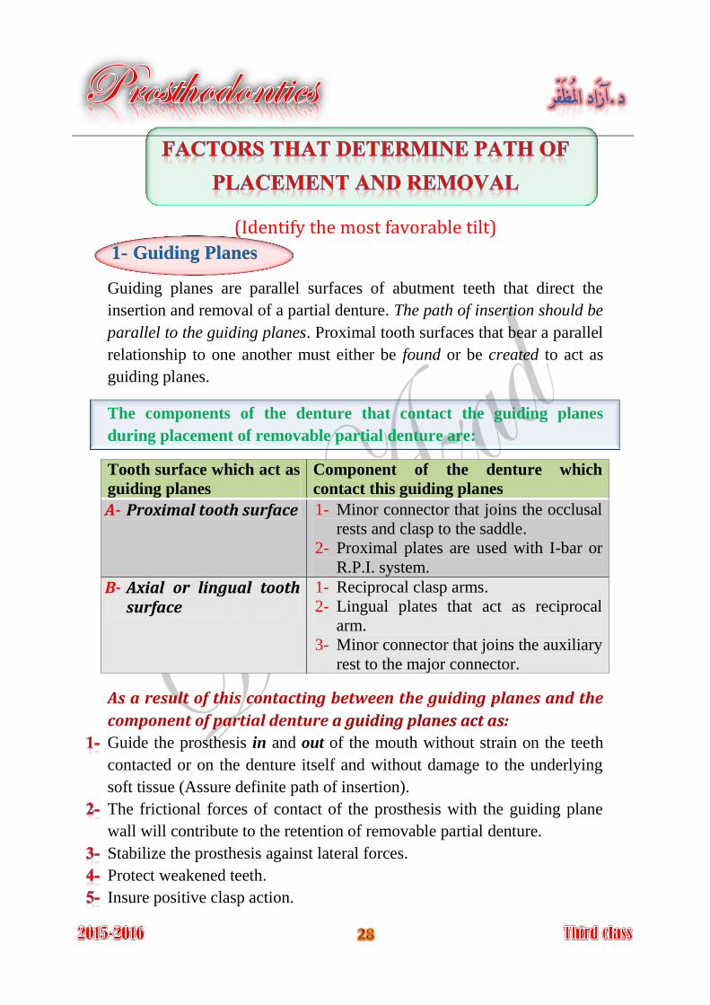
The components of the denture that contact the guiding planes
during placement of removable partial denture are:
Tooth surface which act as
guiding planes
Component of the denture which
contact this guiding planes
A- Proximal tooth surface 1- Minor connector that joins the occlusal
rests and clasp to the saddle.
2- Proximal plates are used with I-bar or
R.P.I. system.
B- Axial or lingual tooth surface
1- Reciprocal clasp arms.
2- Lingual plates that act as reciprocal
arm.
3- Minor connector that joins the auxiliary
rest to the major connector.
As a result of this contacting between the guiding planes and the
component of partial denture a guiding planes act as:
Guide the prosthesis in and out of the mouth without strain on the teeth
contacted or on the denture itself and without damage to the underlying
soft tissue (Assure definite path of insertion).
The frictional forces of contact of the prosthesis with the guiding plane
wall will contribute to the retention of removable partial denture.
Stabilize the prosthesis against lateral forces.
Protect weakened teeth.
Insure positive clasp action.
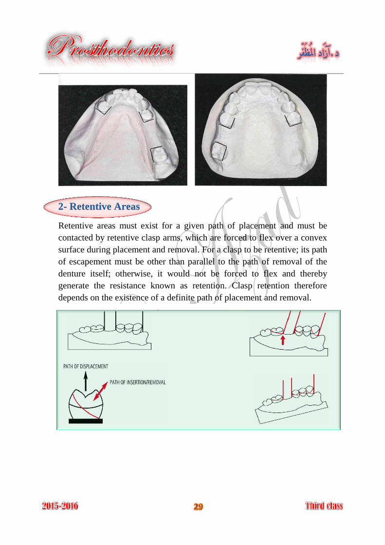
2- Retentive Areas
Retentive areas must exist for a given path of placement and must be
contacted by retentive clasp arms, which are forced to flex over a convex
surface during placement and removal. For a clasp to be retentive; its path
of escapement must be other than parallel to the path of removal of the
denture itself; otherwise, it would not be forced to flex and thereby
generate the resistance known as retention. Clasp retention therefore
depends on the existence of a definite path of placement and removal.
3- Interference
The prosthesis must be designed so that it may be placed and removed
without encountering tooth or soft tissue interference.
If the interference cannot be avoided by changing the path of insertion, so
the interference must be eliminated during mouth preparation (by surgery,
extraction, modifying interfering tooth surfaces, or altering tooth contours
by restorations) or on master cast by a reasonable amount of block-out.
4- Esthetics
To obtain optimum esthetics in removable partial denture therapy:
1- Metal component must be concealed.
Less metal will be displayed (most esthetic location of clasps) if the
retentive clasp is placed at a more distogingival area of tooth surface
made possible either by changing the path of placement selected or by the
contour of the restorations.
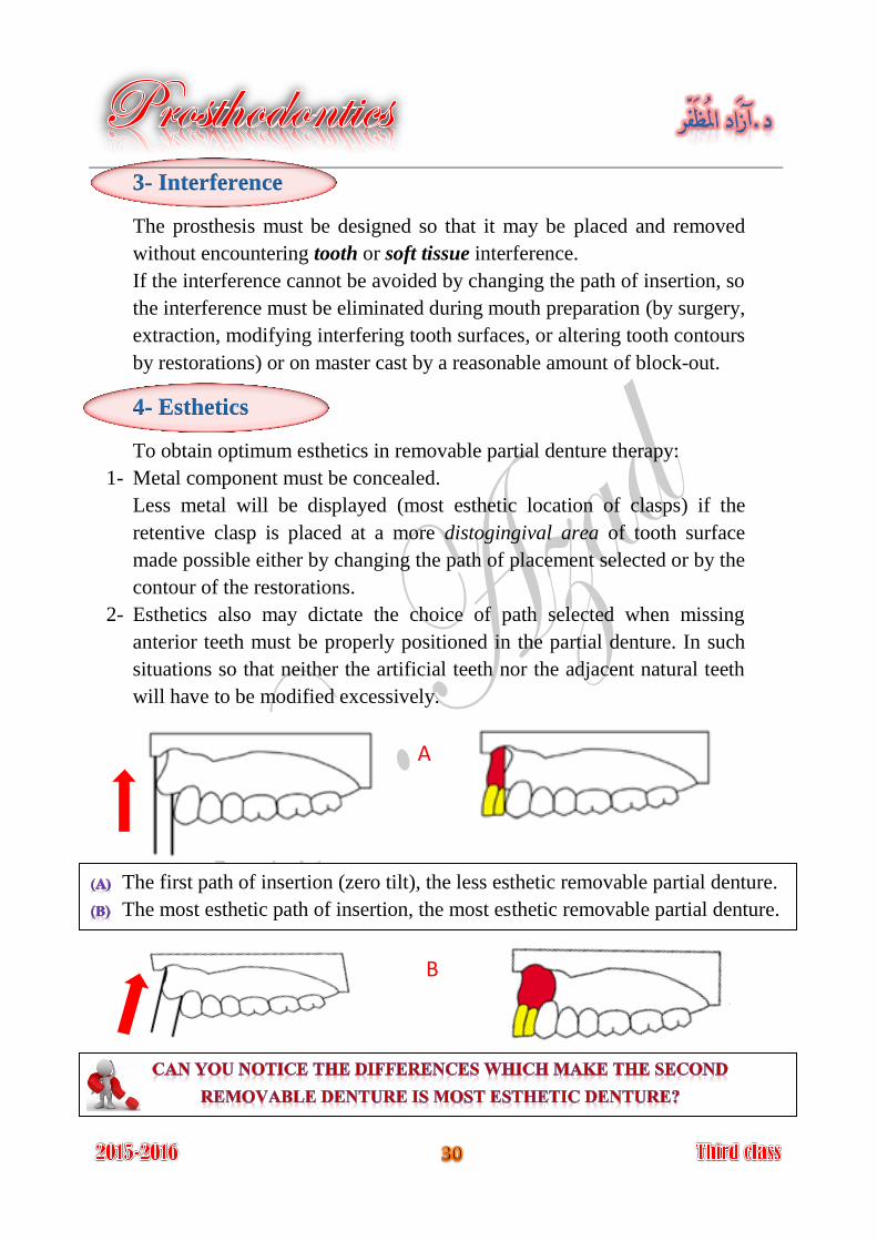
2- Esthetics also may dictate the choice of path selected when missing
anterior teeth must be properly positioned in the partial denture. In such
situations so that neither the artificial teeth nor the adjacent natural teeth
will have to be modified excessively.
The first path of insertion (zero tilt), the less esthetic removable partial denture.
The most esthetic path of insertion, the most esthetic removable partial denture.
A
B
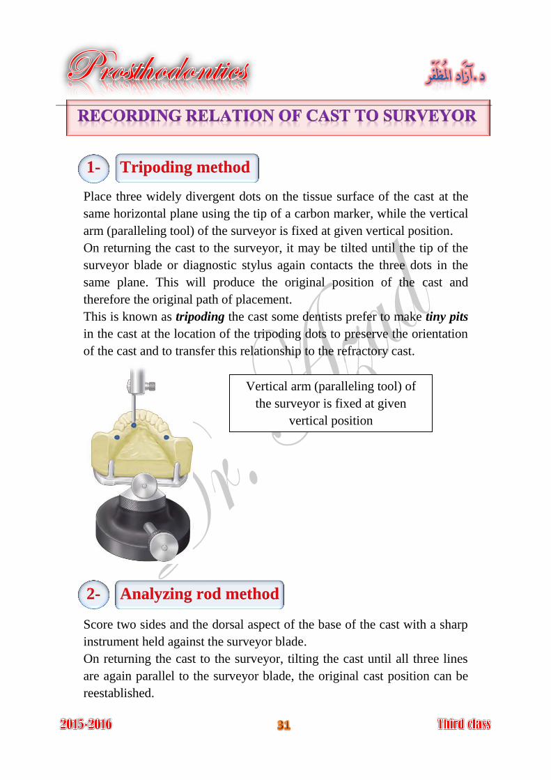
1- Tripoding method
Place three widely divergent dots on the tissue surface of the cast at the
same horizontal plane using the tip of a carbon marker, while the vertical
arm (paralleling tool) of the surveyor is fixed at given vertical position.
On returning the cast to the surveyor, it may be tilted until the tip of the
surveyor blade or diagnostic stylus again contacts the three dots in the
same plane. This will produce the original position of the cast and
therefore the original path of placement.
This is known as tripoding the cast some dentists prefer to make tiny pits
in the cast at the location of the tripoding dots to preserve the orientation
of the cast and to transfer this relationship to the refractory cast.
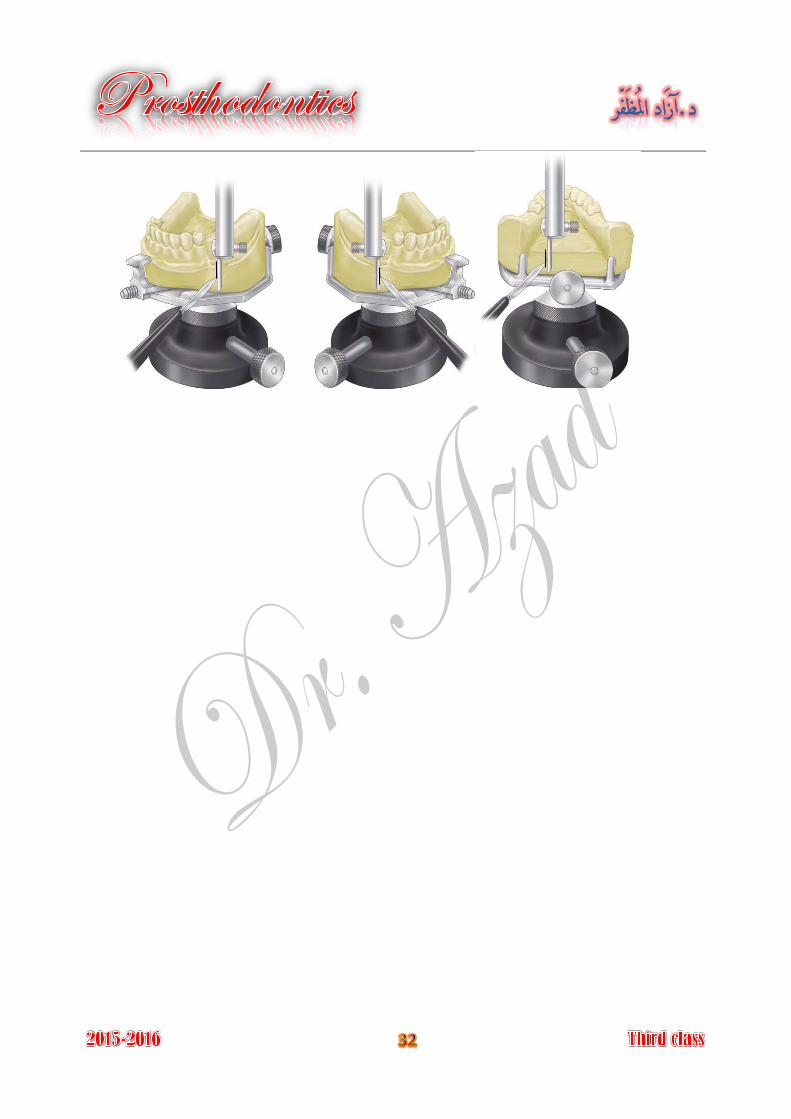
2- Analyzing rod method
Score two sides and the dorsal aspect of the base of the cast with a sharp
instrument held against the surveyor blade.
On returning the cast to the surveyor, tilting the cast until all three lines
are again parallel to the surveyor blade, the original cast position can be
reestablished.
Vertical arm (paralleling tool) of
the surveyor is fixed at given
vertical position
After the master cast has been surveyed and establishment of the path of
placement and the location of undercut areas on the master cast, any
undercut areas that will be crossed by rigid parts of the denture (which is
every part of the denture framework except the retentive clasp
terminals) must be eliminated by blockout.
It is act of placing wax into undercuts that will be crossed by Blockout
rigid parts of the denture except the retentive clasp terminals; this step
was done on the master cast before duplication.
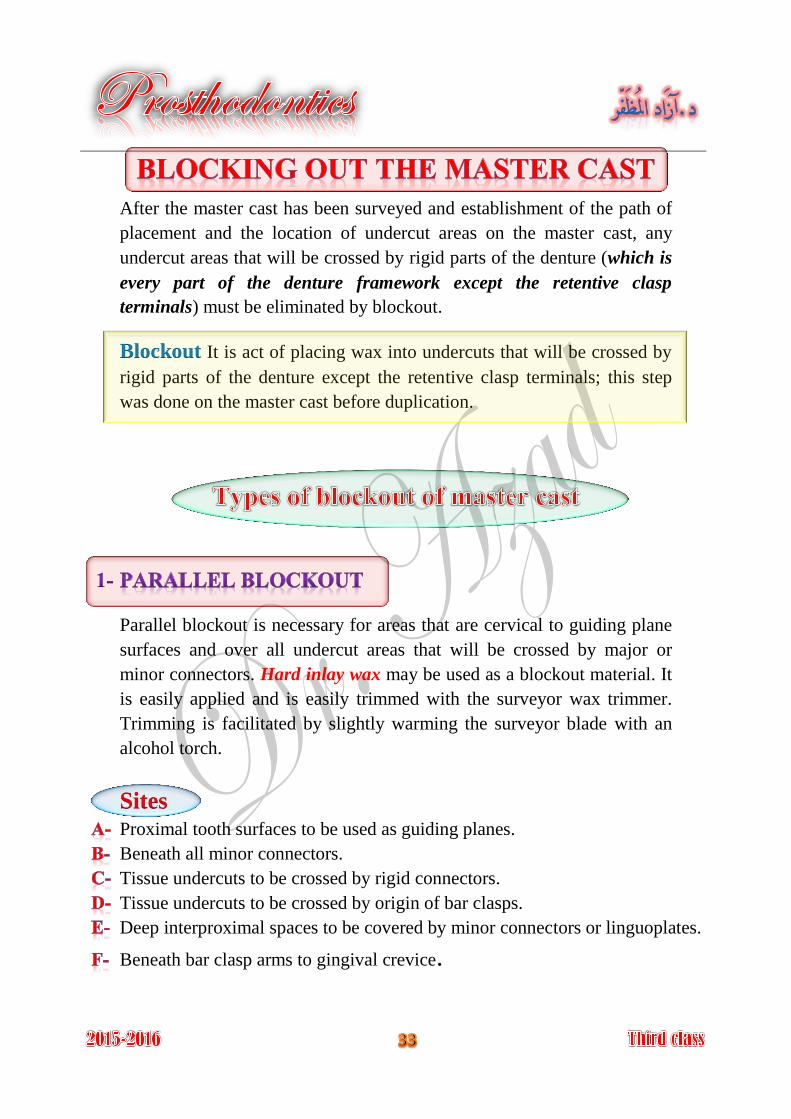
Parallel blockout is necessary for areas that are cervical to guiding plane
surfaces and over all undercut areas that will be crossed by major or
minor connectors. Hard inlay wax may be used as a blockout material. It
is easily applied and is easily trimmed with the surveyor wax trimmer.
Trimming is facilitated by slightly warming the surveyor blade with an
alcohol torch.
Sites Proximal tooth surfaces to be used as guiding planes.
Beneath all minor connectors.
Tissue undercuts to be crossed by rigid connectors.
Tissue undercuts to be crossed by origin of bar clasps.
Deep interproximal spaces to be covered by minor connectors or linguoplates.
Beneath bar clasp arms to gingival crevice.
All guiding plane areas must be parallel to path of placement, and all
other areas that will be contacted by rigid parts of denture framework
must be made free of undercut by parallel blockout.
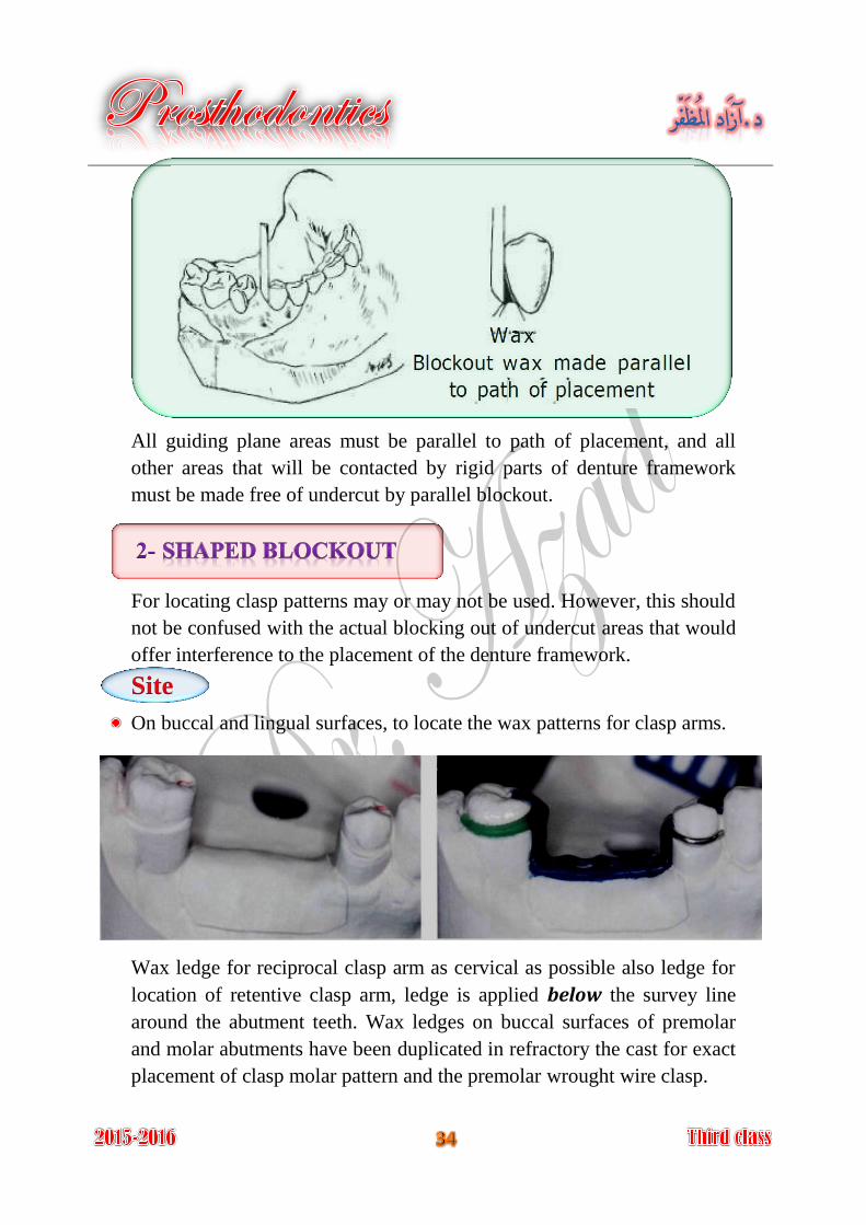
For locating clasp patterns may or may not be used. However, this should
not be confused with the actual blocking out of undercut areas that would
offer interference to the placement of the denture framework.
Site
On buccal and lingual surfaces, to locate the wax patterns for clasp arms.
Wax ledge for reciprocal clasp arm as cervical as possible also ledge for
location of retentive clasp arm, ledge is applied below the survey line
around the abutment teeth. Wax ledges on buccal surfaces of premolar
and molar abutments have been duplicated in refractory the cast for exact
placement of clasp molar pattern and the premolar wrought wire clasp.
Such areas are the labial surfaces and labial undercuts not involved in the
denture design and the sublingual and distolingual areas beyond the limits
of the denture design. These are blocked out arbitrarily with hard
baseplate wax, but because they have no relation to the path of
placement, they do not require the use of the surveyor.
Arbitrary block out is done to:
Prevent distortion of duplicating mold when the master cast is removed. 1-
Facilitate removal of refractory cast from impression during duplication. 2-
Sites All gingival crevices.
Gross tissue undercuts situated below areas involved in design of denture
framework.
Tissue undercuts distal to cast framework.
Labial and buccal tooth and tissue undercuts not involved in denture
design.
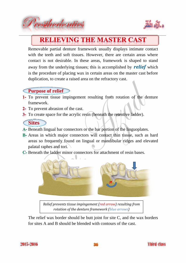
Removable partial denture framework usually displays intimate contact
with the teeth and soft tissues. However, there are certain areas where
contact is not desirable. In these areas, framework is shaped to stand
away from the underlying tissues; this is accomplished by relief which
is the procedure of placing wax in certain areas on the master cast before
duplication, to create a raised area on the refractory cast.
Purpose of relief
To prevent tissue impingement resulting from rotation of the denture
framework.
To prevent abrasion of the cast.
To create space for the acrylic resin (beneath the retentive ladder).
Sites Beneath lingual bar connectors or the bar portion of the linguoplates.
Areas in which major connectors will contact thin tissue, such as hard
areas so frequently found on lingual or mandibular ridges and elevated
palatal raphes and tori.
Beneath the ladder minor connectors for attachment of resin bases.
The relief wax border should be butt joint for site C, and the wax borders
for sites A and B should be blended with contours of the cast.
Relief prevents tissue impingement (red arrow) resulting from
rotation of the denture framework (blue arrows)
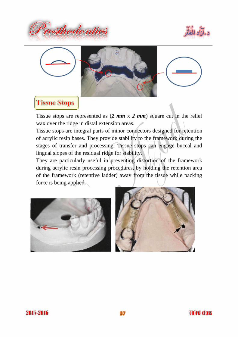
Tissue stops are represented as (2 mm x 2 mm) square cut in the relief
wax over the ridge in distal extension areas.
Tissue stops are integral parts of minor connectors designed for retention
of acrylic resin bases. They provide stability to the framework during the
stages of transfer and processing. Tissue stops can engage buccal and
lingual slopes of the residual ridge for stability.
They are particularly useful in preventing distortion of the framework
during acrylic resin processing procedures, by holding the retention area
of the framework (retentive ladder) away from the tissue while packing
force is being applied.
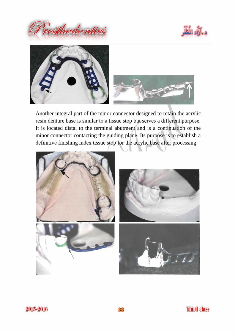
Another integral part of the minor connector designed to retain the acrylic
resin denture base is similar to a tissue stop but serves a different purpose.
It is located distal to the terminal abutment and is a continuation of the
minor connector contacting the guiding plane. Its purpose is to establish a
definitive finishing index tissue stop for the acrylic base after processing.
is the procedure of accurately reproducing a refractory cast. Duplication
To preserve the original master cast.
On the duplicated cast the metal framework may be fitted without
fracture or abrading the original master cast.
It is a cast made of material that will withstand high Refractory cast:
temperature without disintegration when used in partial denture casting
procedure; it has an expansion to compensate for metal shrinkage. The
refractory cast has been made of investment material.
On the duplicated cast the metal framework may be fitted without danger
of fracture or abrading the surface of the original master cast.
An investment cast also may be referred to as a refractory cast because it
is compounded to withstand high temperatures without disintegrating
and, incidentally, to perform certain functions relative to the burnout and
expansion of the mold. A refractory investment is an investment material
that can withstand the high temperatures of casting or soldering.
The investment material is used for making the refractory cast; the type
of investment depends on the type of alloy used.
is used for low heat alloys as type IV gold Gypsum bounded investment
alloy.
is used for high heat alloys as vitallium, Phosphate bounded investment
palladium alloy.
Investment is consisted of powder and special liquid is needed to be
mixed with the powder, special flask that has been used for duplication,
consist of bottom, ring, and feeding tube.
For duplication procedure a duplicating colloid have been used, this
material is agar which reversible hydrocolloid that are capable of being
reused up to four times, they may be prepared and stored in an automatic
duplicating machine. A double boiler can be used to prepare the colloid
for duplication. The clean colloid can be used by cutting it into small
pieces, reheated in this double boiler to a fluid consistency, then tempered
to a working temperature, it will be cooled enough to flow easily without
melting the blocked out wax (63°C).
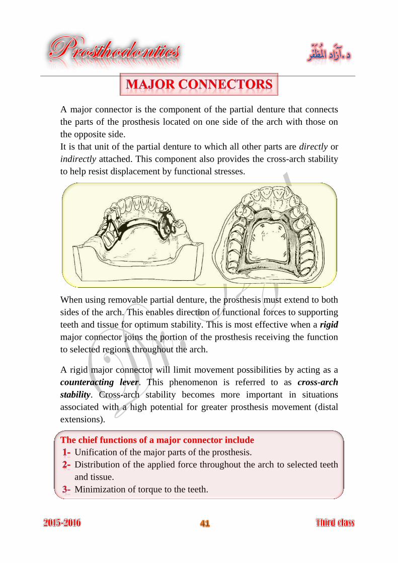
A major connector is the component of the partial denture that connects
the parts of the prosthesis located on one side of the arch with those on
the opposite side.
It is that unit of the partial denture to which all other parts are directly or
indirectly attached. This component also provides the cross-arch stability
to help resist displacement by functional stresses.
When using removable partial denture, the prosthesis must extend to both
sides of the arch. This enables direction of functional forces to supporting
teeth and tissue for optimum stability. This is most effective when a rigid
major connector joins the portion of the prosthesis receiving the function
to selected regions throughout the arch.
A rigid major connector will limit movement possibilities by acting as a
counteracting lever. This phenomenon is referred to as cross-arch
stability. Cross-arch stability becomes more important in situations
associated with a high potential for greater prosthesis movement (distal
extensions).
The chief functions of a major connector include
Unification of the major parts of the prosthesis.
Distribution of the applied force throughout the arch to selected teeth
and tissue.
Minimization of torque to the teeth.
Major connectors should be designed and located with the following
guidelines in mind (characteristics of major connectors):
It is very important; the major connectors should be rigid.
Major connectors should not interfere with the tongue.
Major connectors should not alter the natural contour of mandibular
alveolar ridge or the palatal vault.
Major connectors should not impinge on the oral tissue.
Major connectors should cover no more tissue than is necessary.
Major connectors should not trap food particles.
Major connectors should have support from other elements of the
framework to minimize rotation tendency in function.
Major connectors should contribute to the support of the prosthesis.
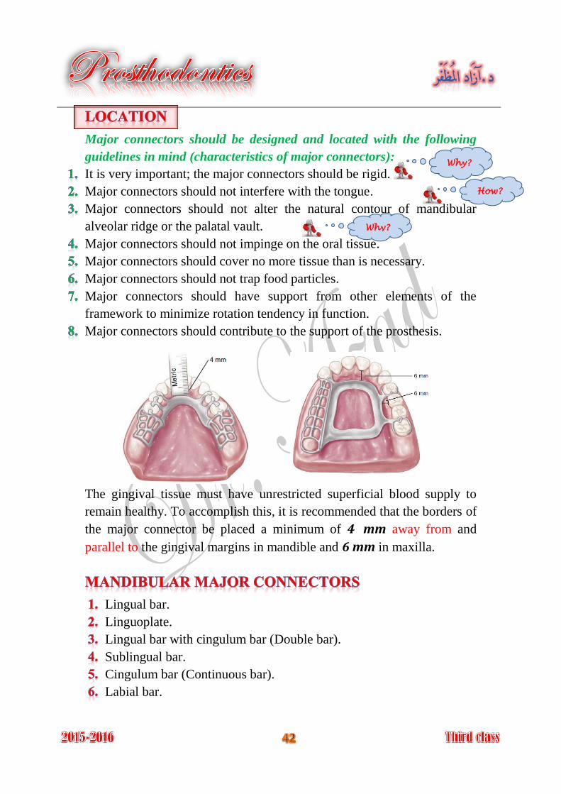
The gingival tissue must have unrestricted superficial blood supply to
remain healthy. To accomplish this, it is recommended that the borders of
the major connector be placed a minimum of 4 mm away from and
parallel to the gingival margins in mandible and 6 mm in maxilla.
Lingual bar.
Linguoplate.
Lingual bar with cingulum bar (Double bar).
Sublingual bar.
Cingulum bar (Continuous bar).
Labial bar.
Why?
How?
Why?
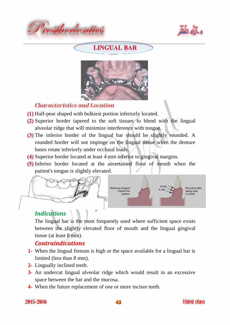
Half-pear shaped with bulkiest portion inferiorly located.
Superior border tapered to the soft tissues to blend with the lingual
alveolar ridge that will minimize interference with tongue.
The inferior border of the lingual bar should be slightly rounded. A
rounded border will not impinge on the lingual tissue when the denture
bases rotate inferiorly under occlusal loads.
Superior border located at least 4 mm inferior to gingival margins.
Inferior border located at the ascertained floor of mouth when the
patient's tongue is slightly elevated.
IndicationsThe lingual bar is the most frequently used where sufficient space exists
between the slightly elevated floor of mouth and the lingual gingival
tissue (at least 8 mm).
Contraindications When the lingual frenum is high or the space available for a lingual bar is 1-
limited (less than 8 mm).
Lingually inclined teeth. 2-
An undercut lingual alveolar ridge which would result in an excessive 3-
space between the bar and the mucosa.
When the future replacement of one or more incisor teeth. 4-
Covers minimum surface area of teeth and tissue therefore potential for
caries, periodontal problems caused by plaque being held in contact with
teeth and tissue is minimal.
It is relatively small, inconspicuously located and minimally interfere
with functions, so patient prefers lingual bar over linguoplate.
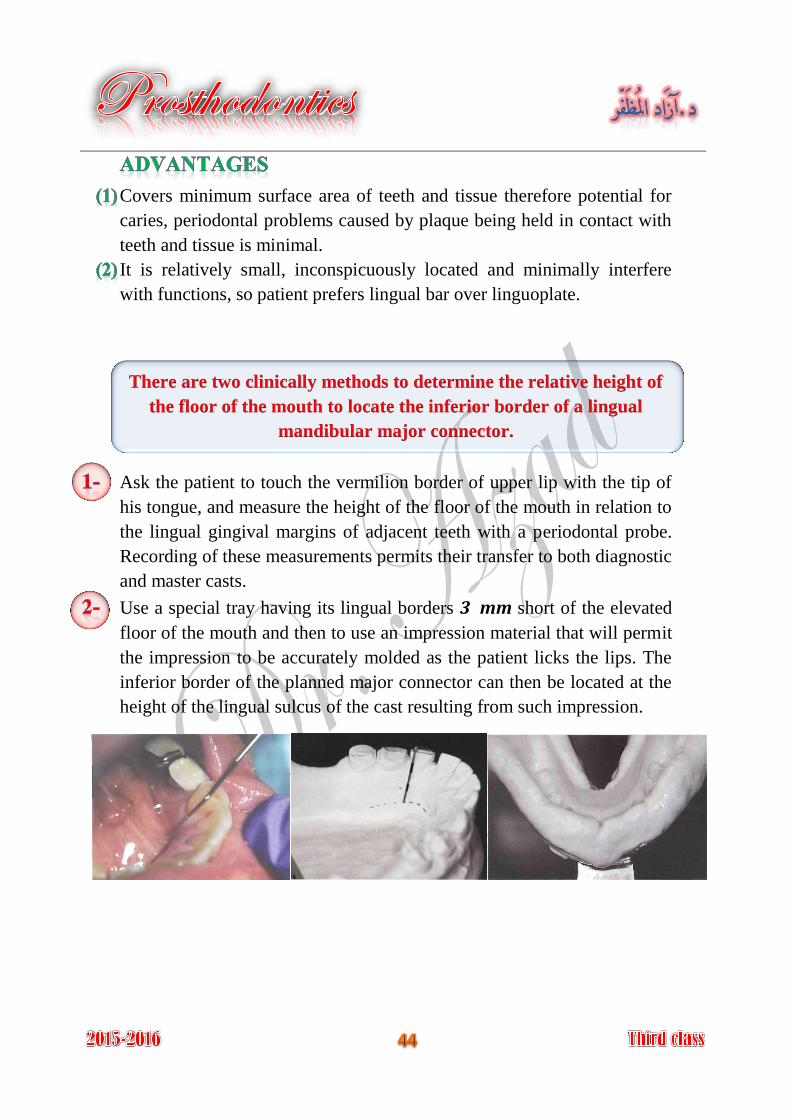
There are two clinically methods to determine the relative height of
the floor of the mouth to locate the inferior border of a lingual
mandibular major connector.
Ask the patient to touch the vermilion border of upper lip with the tip of
his tongue, and measure the height of the floor of the mouth in relation to
the lingual gingival margins of adjacent teeth with a periodontal probe.
Recording of these measurements permits their transfer to both diagnostic
and master casts.
Use a special tray having its lingual borders 3 mm short of the elevated
floor of the mouth and then to use an impression material that will permit
the impression to be accurately molded as the patient licks the lips. The
inferior border of the planned major connector can then be located at the
height of the lingual sulcus of the cast resulting from such impression.
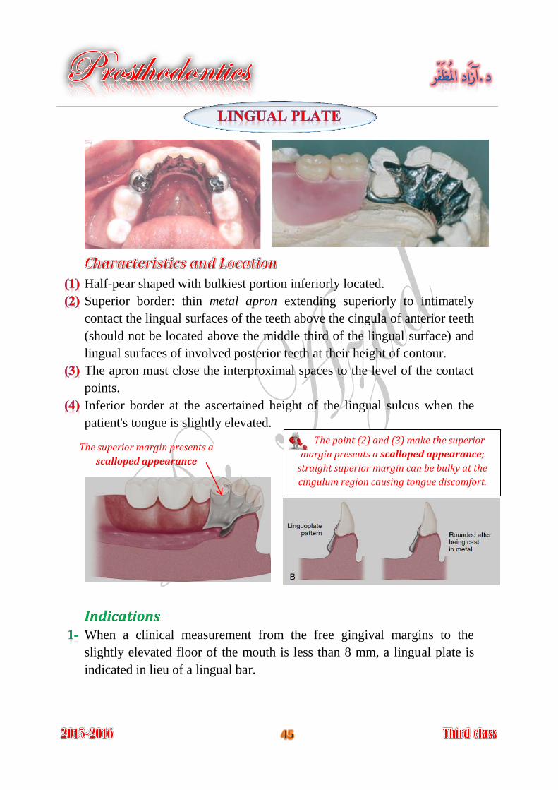
Half-pear shaped with bulkiest portion inferiorly located.
Superior border: thin metal apron extending superiorly to intimately
contact the lingual surfaces of the teeth above the cingula of anterior teeth
(should not be located above the middle third of the lingual surface) and
lingual surfaces of involved posterior teeth at their height of contour.
The apron must close the interproximal spaces to the level of the contact
points.
Inferior border at the ascertained height of the lingual sulcus when the
patient's tongue is slightly elevated.
Indications When a clinical measurement from the free gingival margins to the
slightly elevated floor of the mouth is less than 8 mm, a lingual plate is
indicated in lieu of a lingual bar.
The point (2) and (3) make the superior
margin presents a scalloped appearance;
straight superior margin can be bulky at the
cingulum region causing tongue discomfort.
The superior margin presents a
scalloped appearance
When the residual ridges in Class I arch have undergone such vertical
resorption that they will offer only minimal resistance to horizontal
rotations of the denture through its bases.
When a removable partial denture will replace all mandibular
posterior teeth, a lingual plate should be used.
When the remaining teeth are periodontally weakened; the lingual plate
may be used to splint these weak teeth, and to distribute applied forces
over the remaining teeth in group function to furnish support to the
prosthesis.
When the future replacement of one or more incisor teeth will be
facilitated by the addition of retention loops to an existing linguoplate.
Mandibular tori which must be covered by removable partial denture,
because they cannot be surgically removed or avoided in the design.
(Relief is provided between the torus and the framework)
Contraindications Overlapped anterior teeth, that leads to small gaps between the superior 1.
edge of the plate and the teeth.
Lingually inclined teeth. 2.
Open cervical embrasures where the plate would be visible, so a lingual 3.
bar with continuous bar or labial bar should be considered.
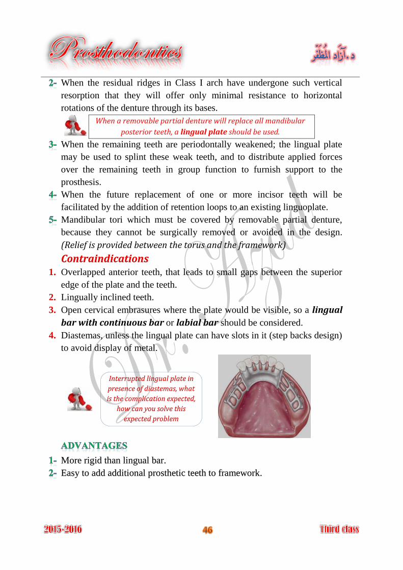
Diastemas, unless the lingual plate can have slots in it (step backs design) 4.
to avoid display of metal.
More rigid than lingual bar.
Easy to add additional prosthetic teeth to framework.
Interrupted lingual plate in
presence of diastemas, what
is the complication expected,
how can you solve this
expected problem
Covers more teeth and tissue surface than lingual bar.
May be more noticeable to the patient than lingual bar.
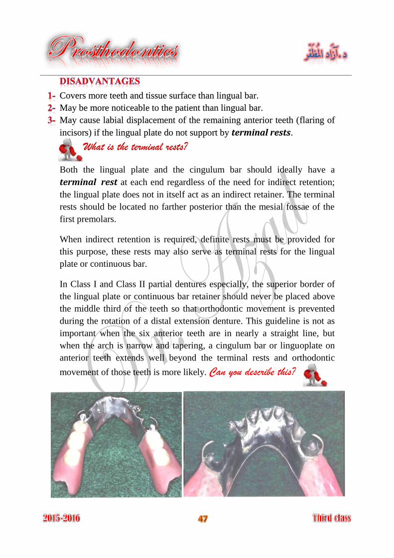
May cause labial displacement of the remaining anterior teeth (flaring of
incisors) if the lingual plate do not support by terminal rests.
What is the terminal rests?
Both the lingual plate and the cingulum bar should ideally have a
terminal rest at each end regardless of the need for indirect retention;
the lingual plate does not in itself act as an indirect retainer. The terminal
rests should be located no farther posterior than the mesial fossae of the
first premolars.
When indirect retention is required, definite rests must be provided for
this purpose, these rests may also serve as terminal rests for the lingual
plate or continuous bar.
In Class I and Class II partial dentures especially, the superior border of
the lingual plate or continuous bar retainer should never be placed above
the middle third of the teeth so that orthodontic movement is prevented
during the rotation of a distal extension denture. This guideline is not as
important when the six anterior teeth are in nearly a straight line, but
when the arch is narrow and tapering, a cingulum bar or linguoplate on
anterior teeth extends well beyond the terminal rests and orthodontic
movement of those teeth is more likely. Can you describe this?
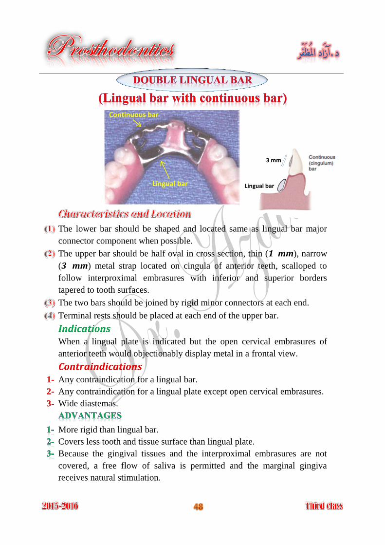
The lower bar should be shaped and located same as lingual bar major
connector component when possible.
The upper bar should be half oval in cross section, thin (1 mm), narrow
(3 mm) metal strap located on cingula of anterior teeth, scalloped to
follow interproximal embrasures with inferior and superior borders
tapered to tooth surfaces.
The two bars should be joined by rigid minor connectors at each end.
Terminal rests should be placed at each end of the upper bar.
Indications When a lingual plate is indicated but the open cervical embrasures of
anterior teeth would objectionably display metal in a frontal view.
Contraindications Any contraindication for a lingual bar. 1-
Any contraindication for a lingual plate except open cervical embrasures. 2-
Wide diastemas. 3-
More rigid than lingual bar.
Covers less tooth and tissue surface than lingual plate.
Because the gingival tissues and the interproximal embrasures are not
covered, a free flow of saliva is permitted and the marginal gingiva
receives natural stimulation.
Lingual bar
Continuous bar
Lingual bar
3 mm
Very complex design.
May be objectionable to patient because there are four edges exposed to
the tip of the tongue.
Tendency to trap food debris.
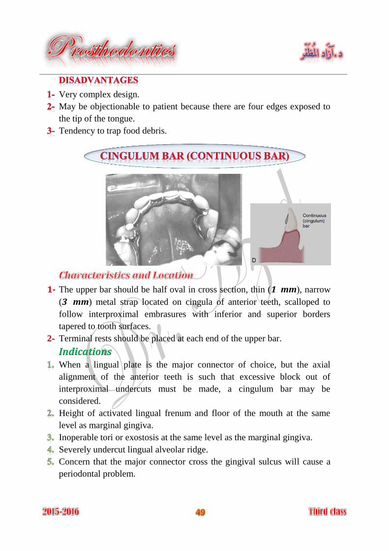
The upper bar should be half oval in cross section, thin (1 mm), narrow 1-
(3 mm) metal strap located on cingula of anterior teeth, scalloped to
follow interproximal embrasures with inferior and superior borders
tapered to tooth surfaces.
Terminal rests should be placed at each end of the upper bar. 2-
Indications When a lingual plate is the major connector of choice, but the axial
alignment of the anterior teeth is such that excessive block out of
interproximal undercuts must be made, a cingulum bar may be
considered.
Height of activated lingual frenum and floor of the mouth at the same
level as marginal gingiva.
Inoperable tori or exostosis at the same level as the marginal gingiva.
Severely undercut lingual alveolar ridge.
Concern that the major connector cross the gingival sulcus will cause a
periodontal problem.
Contraindications Anterior teeth severely tilted to the lingual.
When wide diastemas exist between the mandibular anterior teeth and the
cingulum bar would display metal in a frontal view.
Overlapped anterior teeth.
Does not cross the marginal gingiva or overlay the lingual alveolus.
Easy to add prosthetic teeth to framework.
Must be bulky to have sufficient rigidity and thus may be objectionable to
the patient.
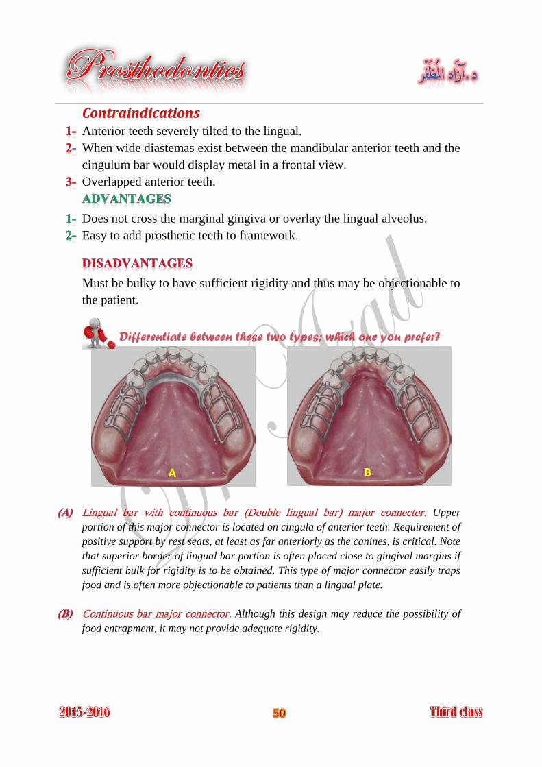
Differentiate between these two types; which one you prefer?
Upper Lingual bar with continuous bar (Double lingual bar) major connector.
portion of this major connector is located on cingula of anterior teeth. Requirement of
positive support by rest seats, at least as far anteriorly as the canines, is critical. Note
that superior border of lingual bar portion is often placed close to gingival margins if
sufficient bulk for rigidity is to be obtained. This type of major connector easily traps
food and is often more objectionable to patients than a lingual plate.
Although this design may reduce the possibility of Continuous bar major connector.
food entrapment, it may not provide adequate rigidity.
A B
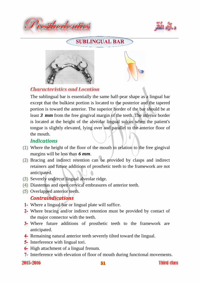
The sublingual bar is essentially the same half-pear shape as a lingual bar
except that the bulkiest portion is located to the posterior and the tapered
portion is toward the anterior. The superior border of the bar should be at
least 3 mm from the free gingival margin of the teeth. The inferior border
is located at the height of the alveolar lingual sulcus when the patient's
tongue is slightly elevated, lying over and parallel to the anterior floor of
the mouth.
Indications Where the height of the floor of the mouth in relation to the free gingival
margins will be less than 6 mm.
Bracing and indirect retention can be provided by clasps and indirect
retainers and future additions of prosthetic teeth to the framework are not
anticipated.
Severely undercut lingual alveolar ridge.
Diastemas and open cervical embrasures of anterior teeth.
Overlapped anterior teeth.
Contraindications Where a lingual bar or lingual plate will suffice.
Where bracing and/or indirect retention must be provided by contact of
the major connector with the teeth.
Where future additions of prosthetic teeth to the framework are
anticipated.
Remaining natural anterior teeth severely tilted toward the lingual.
Interference with lingual tori.
High attachment of a lingual frenum.
Interference with elevation of floor of mouth during functional movements.
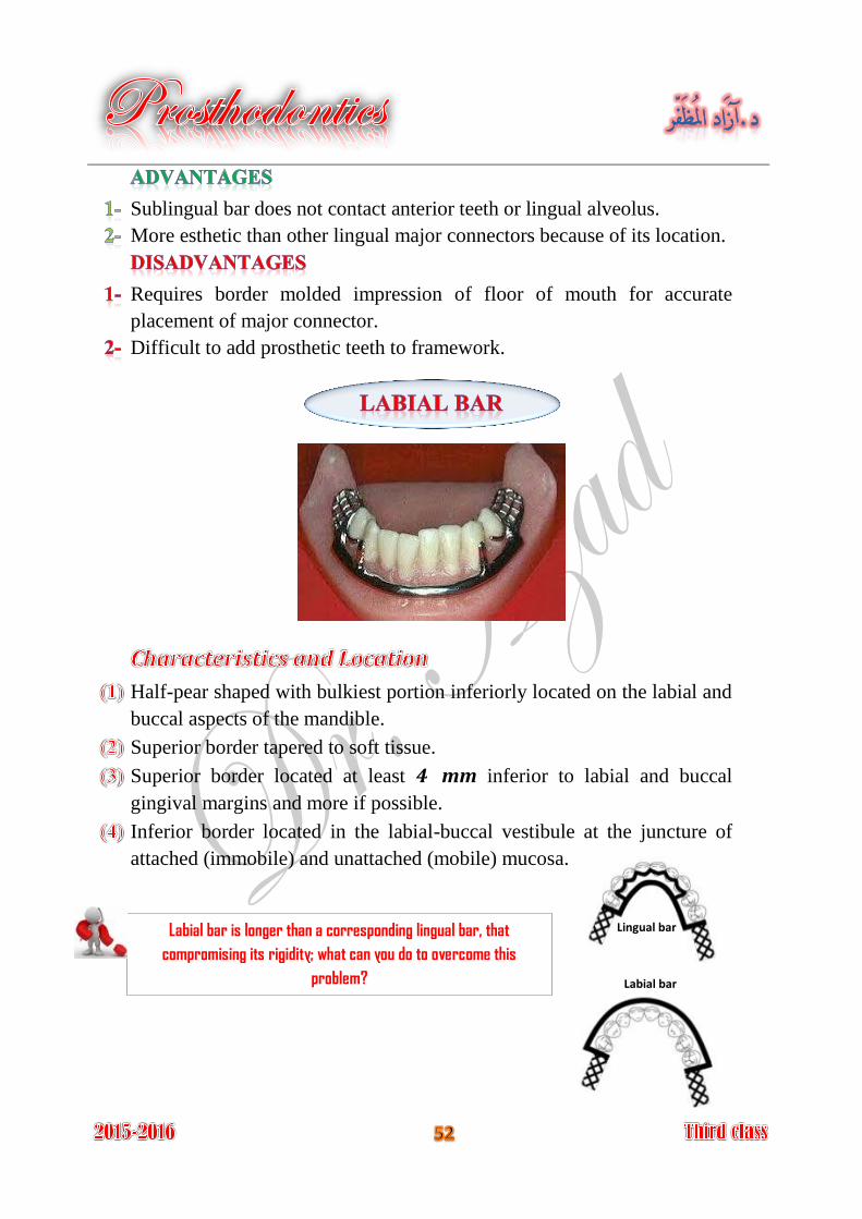
Sublingual bar does not contact anterior teeth or lingual alveolus.
More esthetic than other lingual major connectors because of its location.
Requires border molded impression of floor of mouth for accurate
placement of major connector.
Difficult to add prosthetic teeth to framework.
Half-pear shaped with bulkiest portion inferiorly located on the labial and
buccal aspects of the mandible.
Superior border tapered to soft tissue.
Superior border located at least 4 mm inferior to labial and buccal
gingival margins and more if possible.
Inferior border located in the labial-buccal vestibule at the juncture of
attached (immobile) and unattached (mobile) mucosa.
Labial bar is longer than a corresponding lingual bar, that
compromising its rigidity; what can you do to overcome this
problem?
Lingual bar
Labial bar
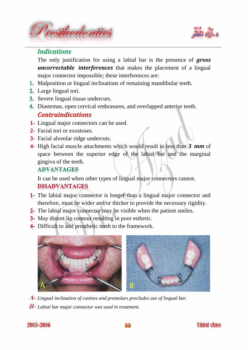
Indications The only justification for using a labial bar is the presence of gross
uncorrectable interferences that makes the placement of a lingual
major connector impossible; these interferences are:
Malposition or lingual inclinations of remaining mandibular teeth.
Large lingual tori.
Severe lingual tissue undercuts.
Diastemas, open cervical embrasures, and overlapped anterior teeth.
Contraindications Lingual major connectors can be used. 1-
Facial tori or exostoses. 2-
Facial alveolar ridge undercuts. 3-
High facial muscle attachments which would result in less than 3 mm of 4-
space between the superior edge of the labial bar and the marginal
gingiva of the teeth.
It can be used when other types of lingual major connectors cannot.
The labial major connector is longer than a lingual major connector and
therefore, must be wider and/or thicker to provide the necessary rigidity.
The labial major connector may be visible when the patient smiles.
May distort lip contour resulting in poor esthetic.
Difficult to add prosthetic teeth to the framework.
Lingual inclination of canines and premolars precludes use of lingual bar.
Labial bar major connector was used in treatment.
A B
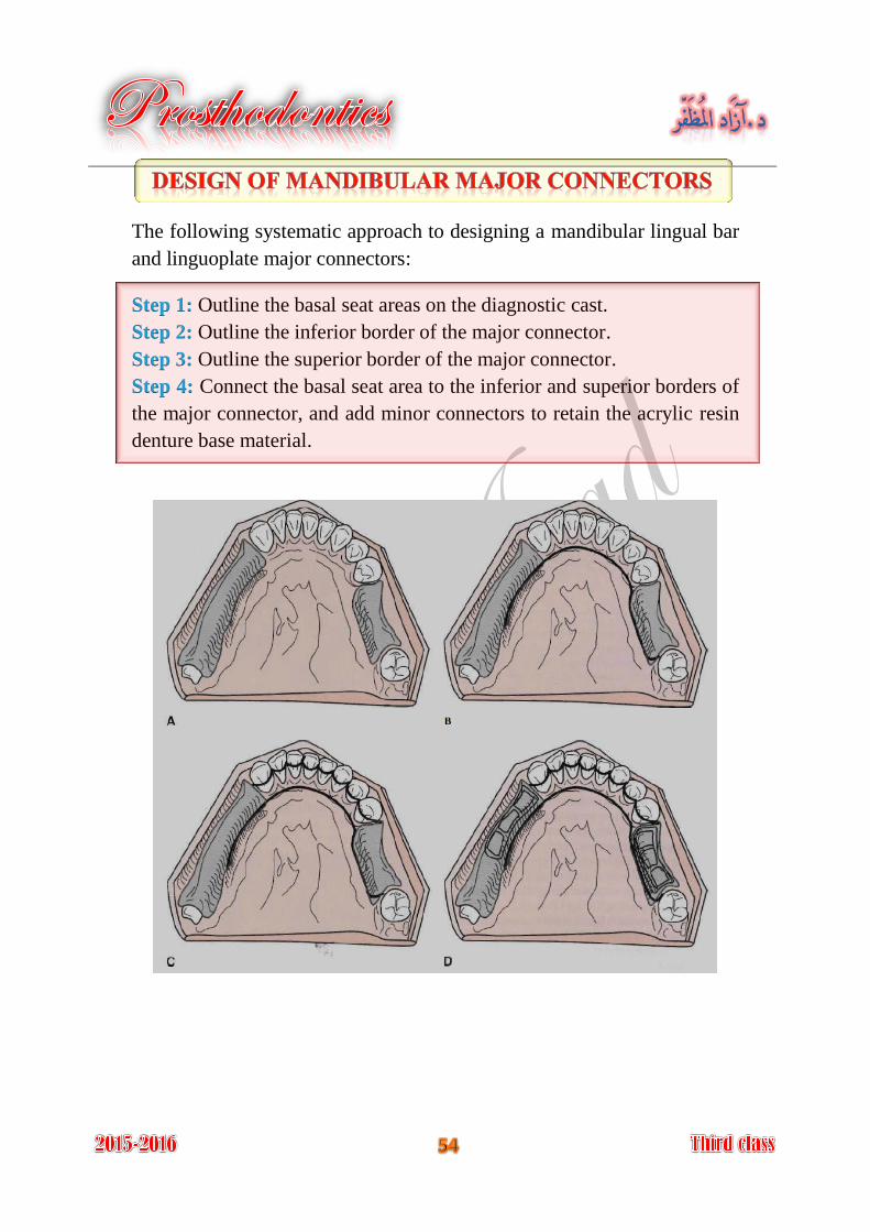
The following systematic approach to designing a mandibular lingual bar
and linguoplate major connectors:
Outline the basal seat areas on the diagnostic cast. Step 1:
Outline the inferior border of the major connector. Step 2:
Outline the superior border of the major connector. Step 3:
Connect the basal seat area to the inferior and superior borders of Step 4:
the major connector, and add minor connectors to retain the acrylic resin
denture base material.
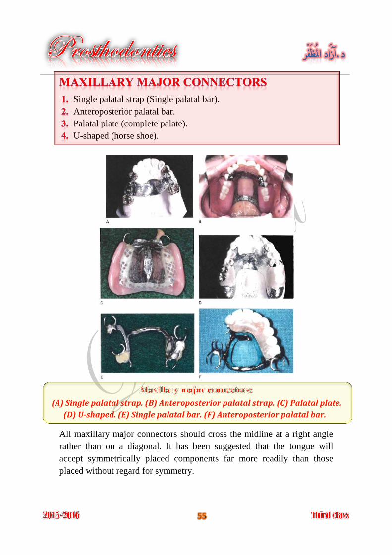
Single palatal strap (Single palatal bar).
Anteroposterior palatal bar.
Palatal plate (complete palate).
U-shaped (horse shoe).
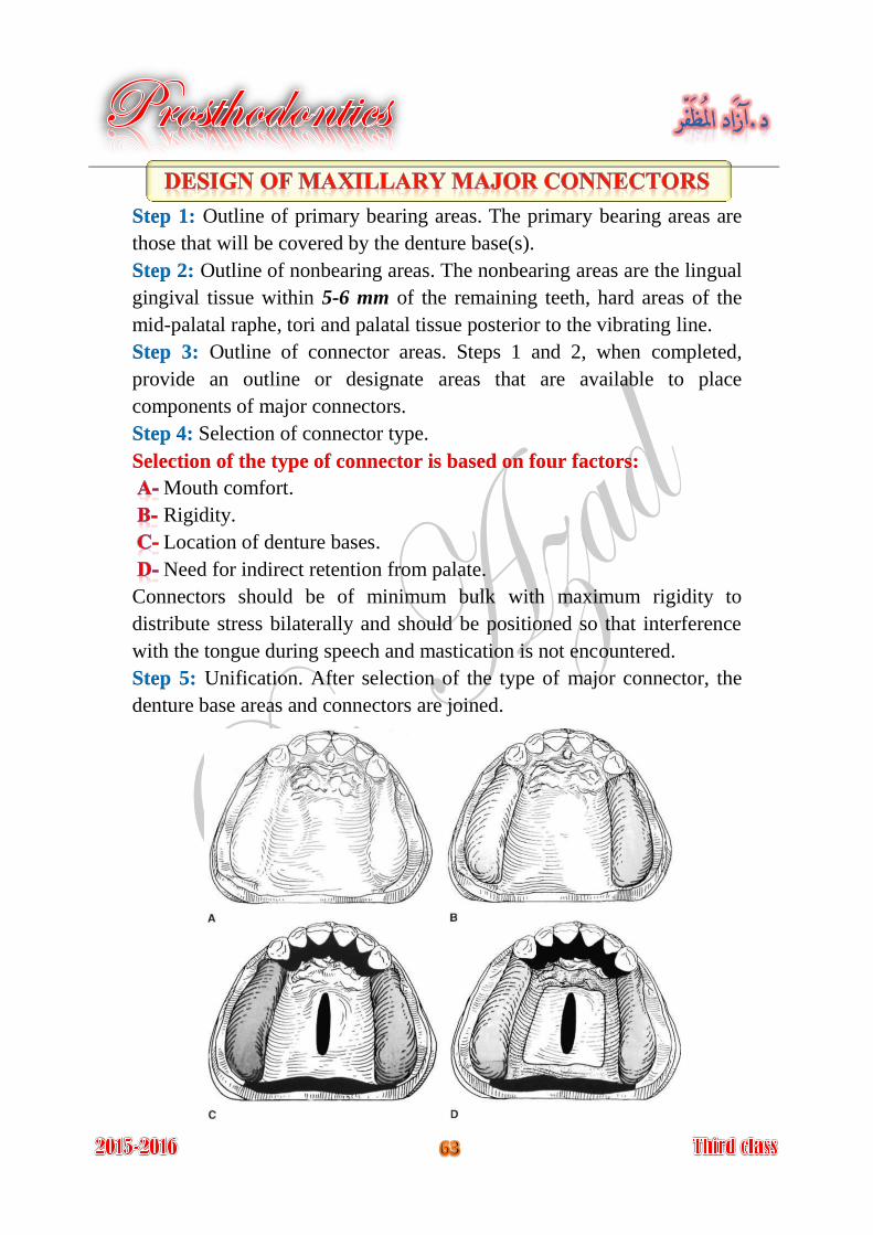
(A) Single palatal strap. (B) Anteroposterior palatal strap. (C) Palatal plate.
(D) U-shaped. (E) Single palatal bar. (F) Anteroposterior palatal bar.
All maxillary major connectors should cross the midline at a right angle
rather than on a diagonal. It has been suggested that the tongue will
accept symmetrically placed components far more readily than those
placed without regard for symmetry.
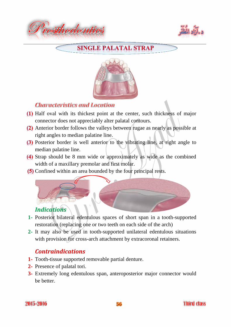
Half oval with its thickest point at the center, such thickness of major
connector does not appreciably alter palatal contours.
Anterior border follows the valleys between rugae as nearly as possible at
right angles to median palatine line.
Posterior border is well anterior to the vibrating line, at right angle to
median palatine line.
Strap should be 8 mm wide or approximately as wide as the combined
width of a maxillary premolar and first molar.
Confined within an area bounded by the four principal rests.
Indications Posterior bilateral edentulous spaces of short span in a tooth-supported 1-
restoration (replacing one or two teeth on each side of the arch)
It may also be used in tooth-supported unilateral edentulous situations 2-
with provision for cross-arch attachment by extracoronal retainers.
Contraindications Tooth-tissue supported removable partial denture. 1-
Presence of palatal tori. 2-
Extremely long edentulous span, anteroposterior major connector would 3-
be better.
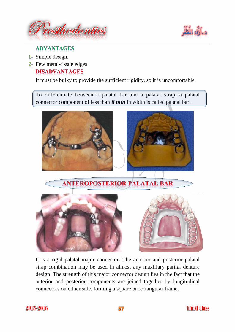
Simple design.
Few metal-tissue edges.
It must be bulky to provide the sufficient rigidity, so it is uncomfortable.
To differentiate between a palatal bar and a palatal strap, a palatal
connector component of less than 8 mm in width is called palatal bar.
It is a rigid palatal major connector. The anterior and posterior palatal
strap combination may be used in almost any maxillary partial denture
design. The strength of this major connector design lies in the fact that the
anterior and posterior components are joined together by longitudinal
connectors on either side, forming a square or rectangular frame.
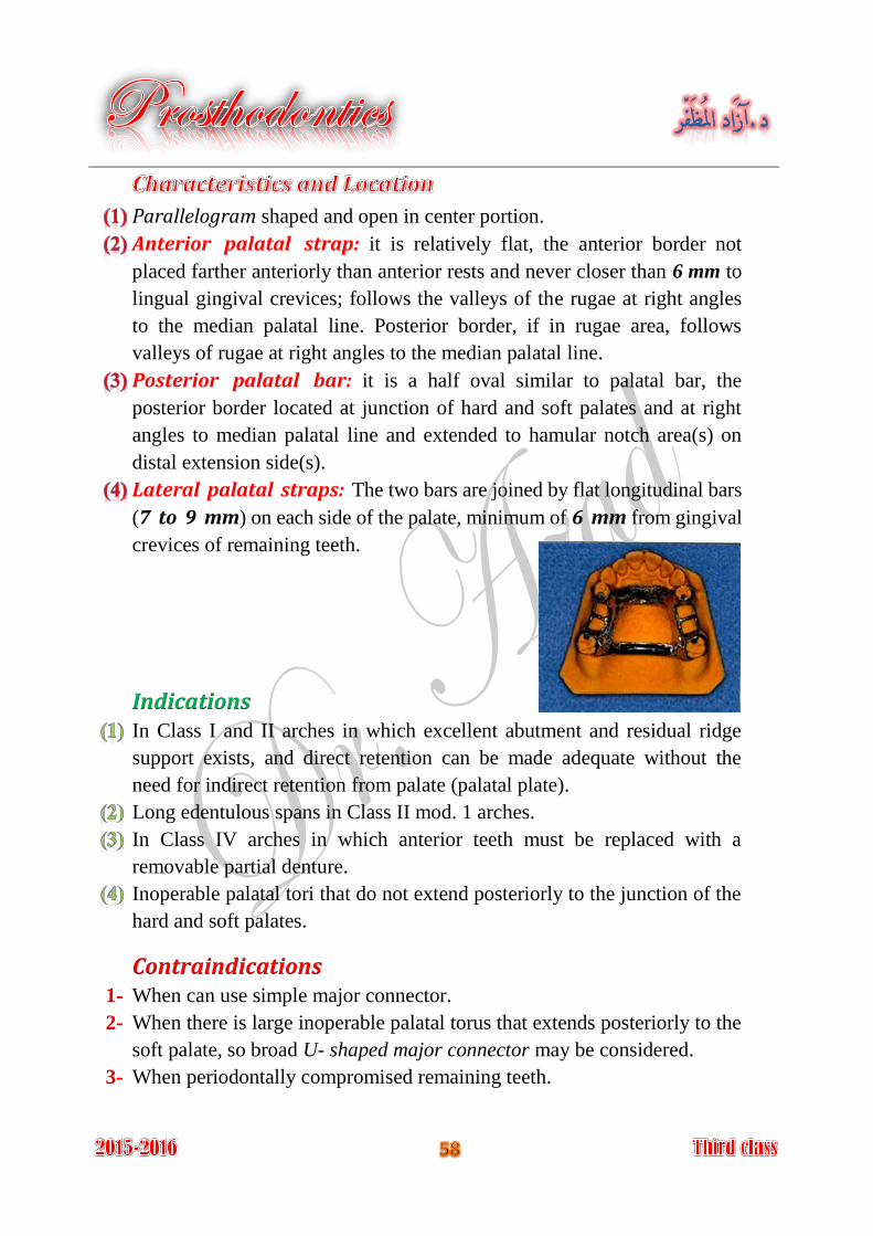
Parallelogram shaped and open in center portion.
Anterior palatal strap: it is relatively flat, the anterior border not
placed farther anteriorly than anterior rests and never closer than 6 mm to
lingual gingival crevices; follows the valleys of the rugae at right angles
to the median palatal line. Posterior border, if in rugae area, follows
valleys of rugae at right angles to the median palatal line.
Posterior palatal bar: it is a half oval similar to palatal bar, the
posterior border located at junction of hard and soft palates and at right
angles to median palatal line and extended to hamular notch area(s) on
distal extension side(s).
Lateral palatal straps: The two bars are joined by flat longitudinal bars
(7 to 9 mm) on each side of the palate, minimum of 6 mm from gingival
crevices of remaining teeth.
Indications In Class I and II arches in which excellent abutment and residual ridge
support exists, and direct retention can be made adequate without the
need for indirect retention from palate (palatal plate).
Long edentulous spans in Class II mod. 1 arches.
In Class IV arches in which anterior teeth must be replaced with a
removable partial denture.
Inoperable palatal tori that do not extend posteriorly to the junction of the
hard and soft palates.
Contraindications When can use simple major connector. 1-
When there is large inoperable palatal torus that extends posteriorly to the 2-
soft palate, so broad U- shaped major connector may be considered.
When periodontally compromised remaining teeth. 3-
The double-strap type of major connector provides the maximum rigidity
without bulk. It covers minimum of palatal tissues than full palatal
coverage.
Very complex design.
A lot of metal-tissue edges.
The anterior border is frequently located in the rugae.
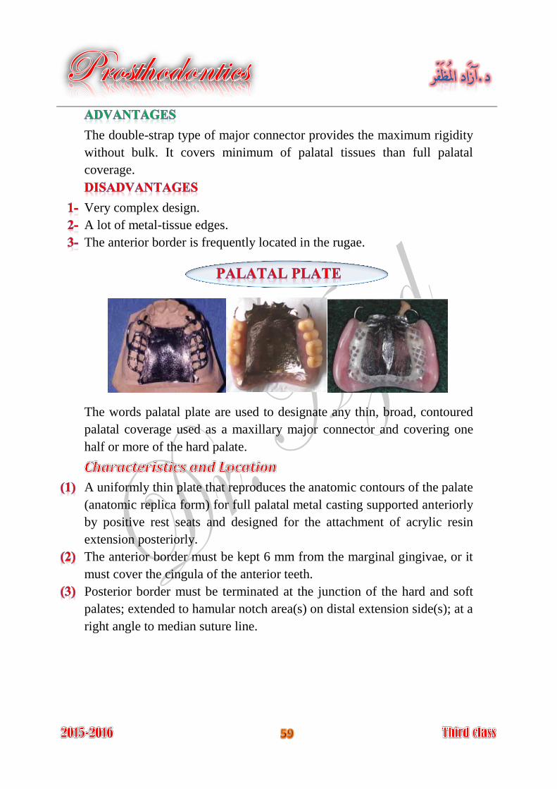
The words palatal plate are used to designate any thin, broad, contoured
palatal coverage used as a maxillary major connector and covering one
half or more of the hard palate.
A uniformly thin plate that reproduces the anatomic contours of the palate
(anatomic replica form) for full palatal metal casting supported anteriorly
by positive rest seats and designed for the attachment of acrylic resin
extension posteriorly.
The anterior border must be kept 6 mm from the marginal gingivae, or it
must cover the cingula of the anterior teeth.
Posterior border must be terminated at the junction of the hard and soft
palates; extended to hamular notch area(s) on distal extension side(s); at a
right angle to median suture line.
Indications When the remaining teeth are periodontally compromised, complete
palatal coverage permits distribution of the applied force to the remaining
teeth, as well as to the palatal tissue.
In Class II arch with large posterior modification space and some missing
anterior teeth.
When the last remaining abutment tooth on either side of a Class I arch is
the canine or first premolar tooth, especially when the residual ridges
have undergone excessive vertical resorption.
In most situations in which only some or all anterior teeth remain.
When relining is anticipated.
ContraindicationsWhen less than complete palatal coverage is necessary and there are
sufficient remaining natural teeth to use a palatal plate or strap major
connector.
Provides the ultimate rigidity.
Provides maximum support, retention, bracing, and direct-indirect
retention from the palate.
Fairly simple design.
Few metal teeth edges.
Easy to add new prosthetic teeth to framework.
Can be easily converted to an interim complete denture.
Covers more teeth and tissues surface than any major connector.
Occasionally, problems with phonetics may be encountered.
There are several design difficulties:
A- The hamular notch, vibrating line area must be located on a master cast.
B- Difficult to adjust the metal-tissue contact.
C- Difficult to reline the metal portion of palatal contact.

The full palatal coverage may be accomplished in one of two ways:
One method is to use a complete cast plate that extends to the junction of A-
the hard and soft palates.
The other method is to use a cast major connector anteriorly with B-
retentive means posteriorly, for the attachment of an acrylic-resin denture
base that extends posteriorly to the posterior palatal seal area.
It is horseshoe connector consist of thin band of metal.
Anterior border areas of this type of connector must be kept at least 6 mm
away from adjacent teeth, or running along the lingual surfaces of the
remaining teeth.
It extends onto palatal tissue for 6-8 mm.
Where it must be used, indirect retainers must support any portion of the
connector extending anteriorly from the principal occlusal rests.
If for any reason the anterior border must contact the remaining teeth, the
connector must again be supported by rests placed in properly prepared
rest seats. It should never be supported even temporarily by inclined
lingual surfaces of anterior teeth.
It should display symmetry and all borders should be gently curved and
smooth.
Retentive mean Acrylic
A B
Indications The U-shaped palatal major connector is the least
desirable design of all palatal major connectors, but it
still used in these situations:
A class IV partially edentulous arch.
A class III or class III mod.1 partially edentulous arch with anterior
edentulous spaces, where cross-arch force distribution is not important.
A partially edentulous arch with an inoperable palatal torus extends to the
posterior limit of the hard palate.
When several anterior teeth are to be replaced.
Contraindications Where support, retention, bracing, and direct-indirect retention from the 1-
palate is necessary.
Distal extension partial dentures, because cross-arch force distribution is 2-
necessary.
Why does the horseshoe connector display limit
cross-arch force distribution?
Minimal coverage of the palate.
Fairly simple design.
Fewer metal-tooth or -tissue edges than anteroposterior design.
It is not rigid as other maxillary major connectors.
Rigidity may be increased by having the metal in the vertical and
horizontal planes. Its lack of rigidity (compared with other designs) can
allow lateral flexure under occlusal forces, which may induce torque or
direct lateral force to abutment teeth.
It is uncomfortable because it covers the rugae, which are highly
enervated area.
Impinging the gingival tissue, this leads to gingival irritation and
periodontal damage.
It is unconservative major connector. For gaining good support for U-
shaped major connector, the occlusal rests should be increase.
Why?
Outline of primary bearing areas. The primary bearing areas are Step 1:
those that will be covered by the denture base(s).
Outline of nonbearing areas. The nonbearing areas are the lingual Step 2:
gingival tissue within 5-6 mm of the remaining teeth, hard areas of the
mid-palatal raphe, tori and palatal tissue posterior to the vibrating line.
Outline of connector areas. Steps 1 and 2, when completed, Step 3:
provide an outline or designate areas that are available to place
components of major connectors.
Selection of connector type. Step 4:
Selection of the type of connector is based on four factors:
Mouth comfort.
Rigidity.
Location of denture bases.
Need for indirect retention from palate.
Connectors should be of minimum bulk with maximum rigidity to
distribute stress bilaterally and should be positioned so that interference
with the tongue during speech and mastication is not encountered.
Unification. After selection of the type of major connector, the Step 5:
denture base areas and connectors are joined.
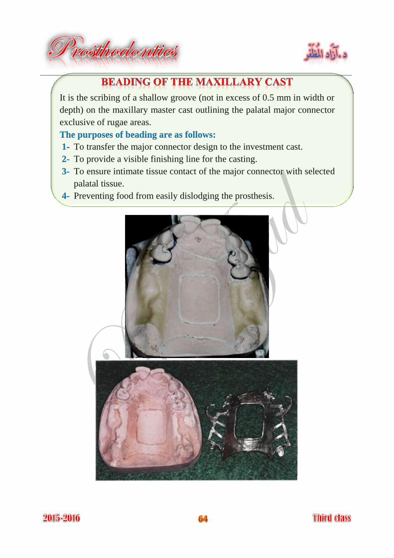
It is the scribing of a shallow groove (not in excess of 0.5 mm in width or
depth) on the maxillary master cast outlining the palatal major connector
exclusive of rugae areas.
The purposes of beading are as follows:
To transfer the major connector design to the investment cast. 1-
To provide a visible finishing line for the casting. 2-
To ensure intimate tissue contact of the major connector with selected 3-
palatal tissue.
Preventing food from easily dislodging the prosthesis. 4-
Minor connectors are those components that serve as connecting link
between the major connector or base of a removable partial denture and
the other components of the prosthesis (such as the clasp assembly,
indirect retainers, occlusal rests, or cingulum rests).
The primary function of a minor connector is to join the denture parts to
major connector.
The minor connector serves other purposes:
To transfer functional stress to the abutment teeth. This is a
(prosthesis-to-abutment function) of the minor connector.
Occlusal forces applied to the artificial teeth are transmitted through the
base to the underlying ridge tissue if that base is primarily tissue
supported.
Occlusal forces applied to the artificial teeth are also transferred to
abutment teeth through occlusal rests. The minor connectors arising from
a rigid major connector make possible this transfer of functional stress
throughout the dental arch.
To transfer the effect of the retainers, rests, and stabilizing
components throughout the prosthesis. This is an (abutment-to-
prosthesis function) of the minor connector. Thus forces applied on one
portion of the denture may be resisted by other components placed
elsewhere in the arch for that purpose. A stabilizing component on one
side of the arch may be placed to resist horizontal forces originating on
the opposite side. This is possible only because of the transferring effect
of the minor connector, which supports that stabilizing component, and
the rigidity of the major connector.
Provide unification and rigidity.
It might help in retention and stability of the prosthesis.
Through its connection to the guiding plane; it helps as a bracing element.
Share in the path of insertion and removal maintenance.
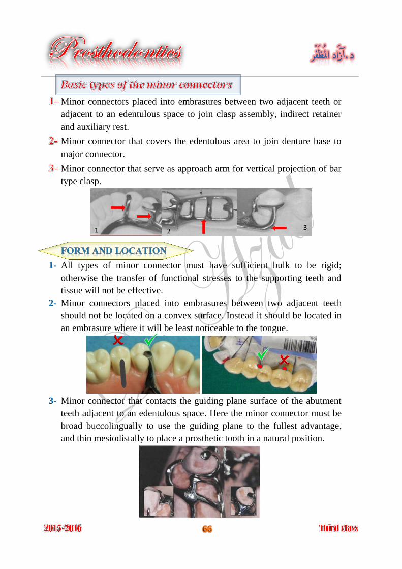
Minor connectors placed into embrasures between two adjacent teeth or
adjacent to an edentulous space to join clasp assembly, indirect retainer
and auxiliary rest.
Minor connector that covers the edentulous area to join denture base to
major connector.
Minor connector that serve as approach arm for vertical projection of bar
type clasp.
All types of minor connector must have sufficient bulk to be rigid; 1-
otherwise the transfer of functional stresses to the supporting teeth and
tissue will not be effective.
Minor connectors placed into embrasures between two adjacent teeth 2-
should not be located on a convex surface. Instead it should be located in
an embrasure where it will be least noticeable to the tongue.
Minor connector that contacts the guiding plane surface of the abutment 3-
teeth adjacent to an edentulous space. Here the minor connector must be
broad buccolingually to use the guiding plane to the fullest advantage,
and thin mesiodistally to place a prosthetic tooth in a natural position.
1 2 3
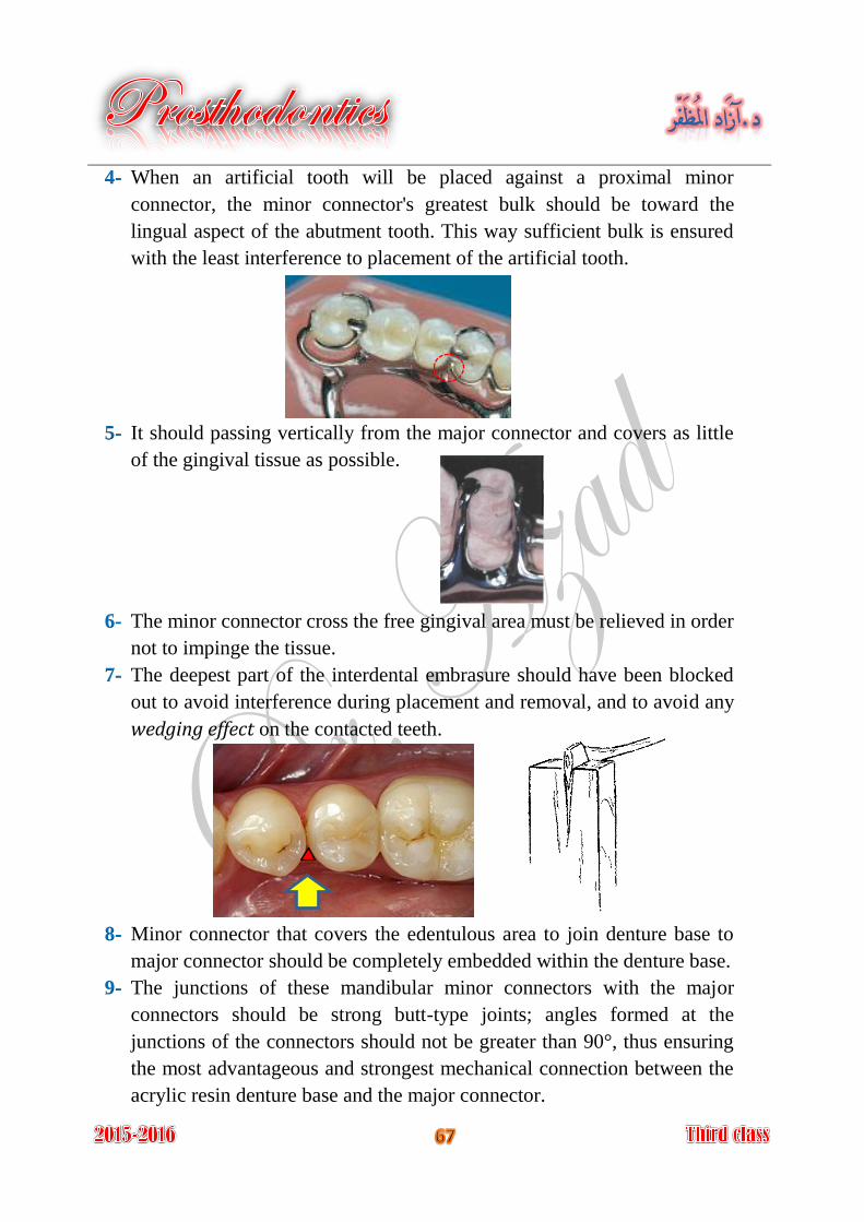
When an artificial tooth will be placed against a proximal minor 4-
connector, the minor connector's greatest bulk should be toward the
lingual aspect of the abutment tooth. This way sufficient bulk is ensured
with the least interference to placement of the artificial tooth.
It should passing vertically from the major connector and covers as little 5-
of the gingival tissue as possible.
The minor connector cross the free gingival area must be relieved in order 6-
not to impinge the tissue.
The deepest part of the interdental embrasure should have been blocked 7-
out to avoid interference during placement and removal, and to avoid any
wedging effect on the contacted teeth.
Minor connector that covers the edentulous area to join denture base to 8-
major connector should be completely embedded within the denture base.
The junctions of these mandibular minor connectors with the major 9-
connectors should be strong butt-type joints; angles formed at the
junctions of the connectors should not be greater than 90°, thus ensuring
the most advantageous and strongest mechanical connection between the
acrylic resin denture base and the major connector.
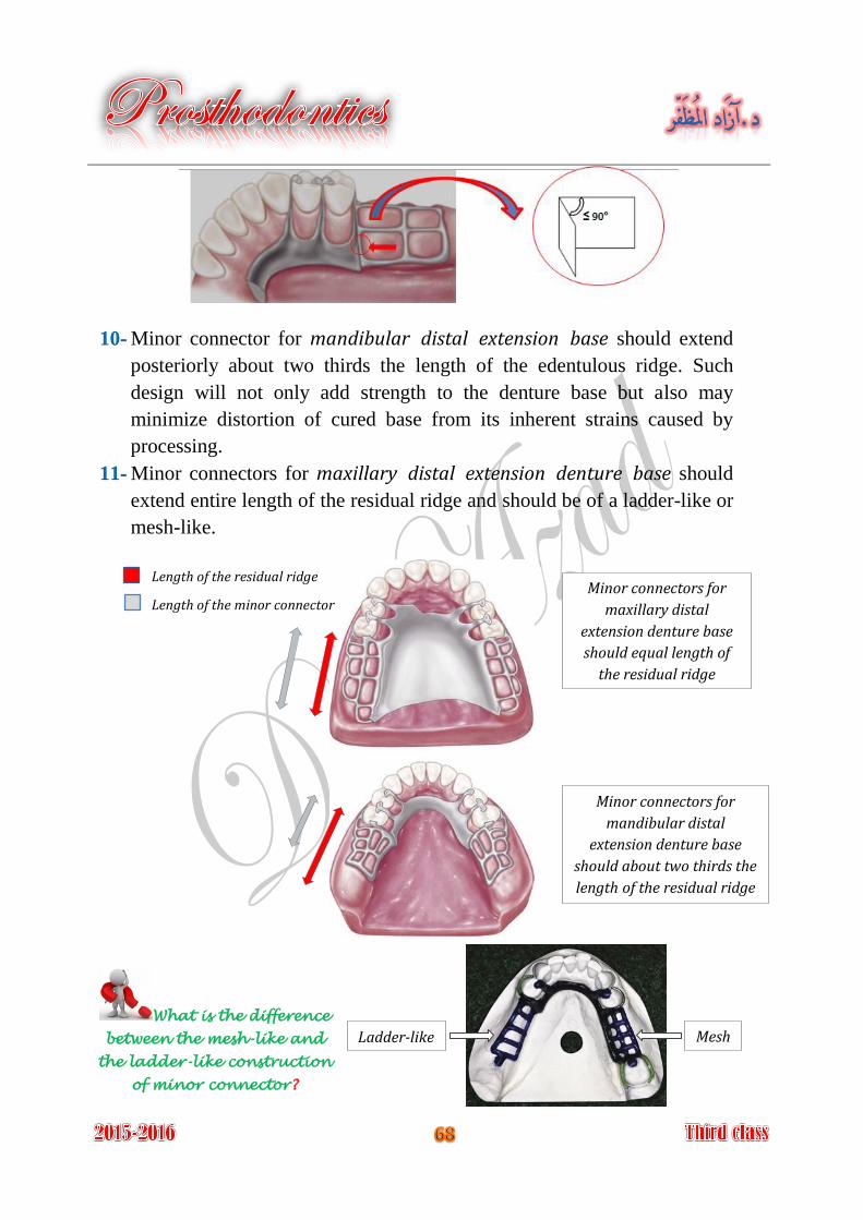
Minor connector for mandibular distal extension base should extend 10-
posteriorly about two thirds the length of the edentulous ridge. Such
design will not only add strength to the denture base but also may
minimize distortion of cured base from its inherent strains caused by
processing.
Minor connectors for maxillary distal extension denture base should 11-
extend entire length of the residual ridge and should be of a ladder-like or
mesh-like.
Minor connectors for
maxillary distal
extension denture base
should equal length of
the residual ridge
Minor connectors for
mandibular distal
extension denture base
should about two thirds the
length of the residual ridge
Mesh Ladder-like
Length of the residual ridge
Length of the minor connector
What is the difference
between the mesh-like and
the ladder-like construction
of minor connector?
Minor connector for vertical projection of bar type clasp approaches the 12-
tooth from an apical direction rather than from an occlusal direction, the
approach arm should display a smooth, even taper from its origin to its
terminus.
Minor connector for vertical projection of bar type clasp must not cross a 13-
soft tissue undercut (need parallel block out).
It is the junction of minor connector that join denture base to major
connector.
The minor connector must be joined to the major connector in angle not
greater than 90°, to ensure rigidity of acrylic denture base and to help
lock the acrylic resin to the major connector. The acrylic resin denture
base must join the major connector in a smooth, even fashion. Any
irregularity or step between the two surfaces will irritate the tongue.
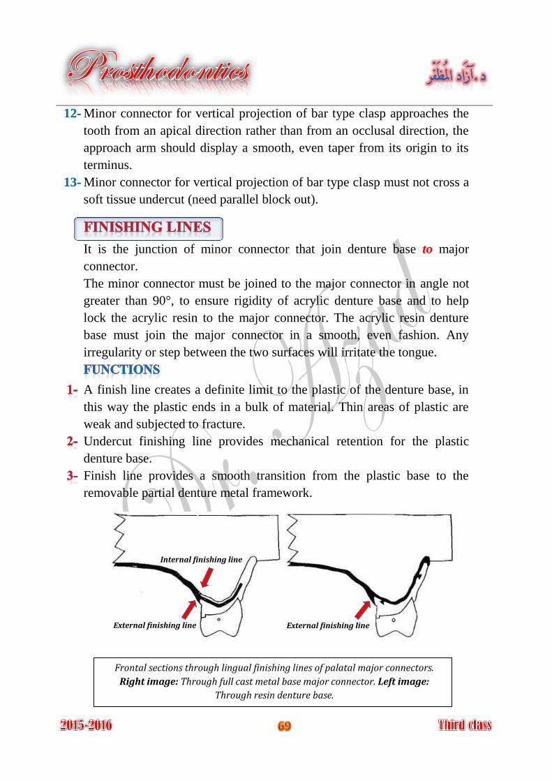
A finish line creates a definite limit to the plastic of the denture base, in
this way the plastic ends in a bulk of material. Thin areas of plastic are
weak and subjected to fracture.
Undercut finishing line provides mechanical retention for the plastic
denture base.
Finish line provides a smooth transition from the plastic base to the
removable partial denture metal framework.
Frontal sections through lingual finishing lines of palatal major connectors.
Right image: Through full cast metal base major connector. Left image:
Through resin denture base.
Internal finishing line
External finishing line External finishing line
If the finishing line is located on the outer surface of major connector, it
is called external finishing line. If it is located on the inner or tissue
surface, it is called internal finishing line.
Of course the medial extent of the minor connector depends on the lateral
extent of the major palatal connector.
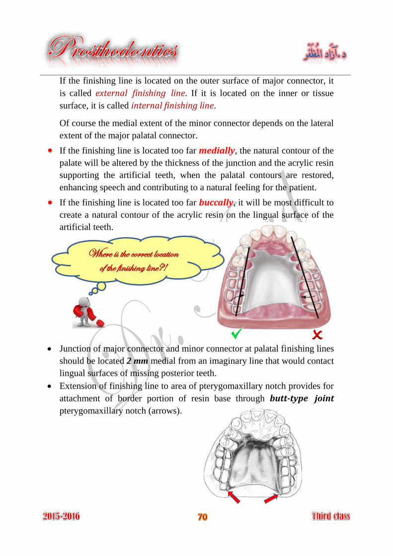
If the finishing line is located too far medially, the natural contour of the
palate will be altered by the thickness of the junction and the acrylic resin
supporting the artificial teeth, when the palatal contours are restored,
enhancing speech and contributing to a natural feeling for the patient.
If the finishing line is located too far buccally, it will be most difficult to
create a natural contour of the acrylic resin on the lingual surface of the
artificial teeth.
Junction of major connector and minor connector at palatal finishing lines
should be located 2 mm medial from an imaginary line that would contact
lingual surfaces of missing posterior teeth.
Extension of finishing line to area of pterygomaxillary notch provides for
attachment of border portion of resin base through butt-type joint
pterygomaxillary notch (arrows).
Where is the correct location of the finishing line?!
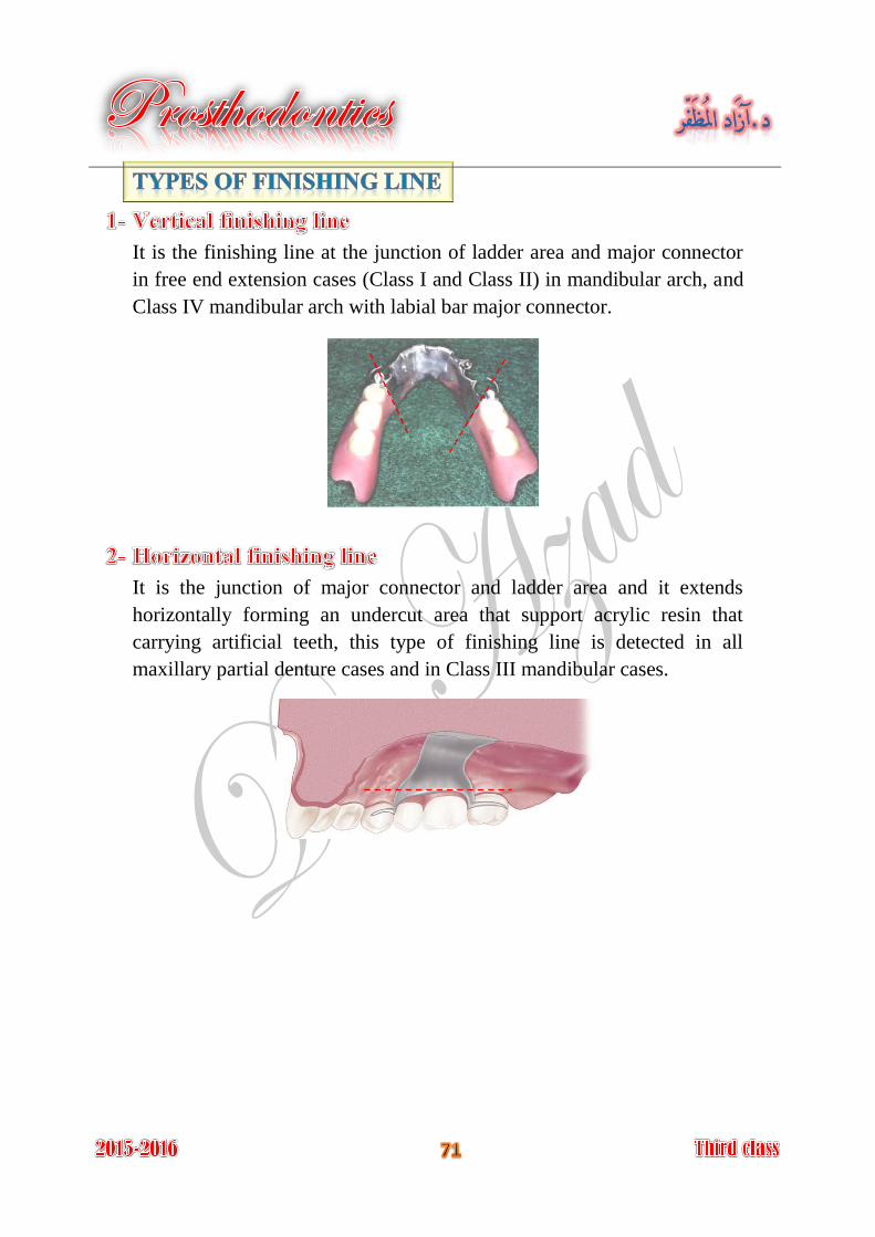
It is the finishing line at the junction of ladder area and major connector
in free end extension cases (Class I and Class II) in mandibular arch, and
Class IV mandibular arch with labial bar major connector.
It is the junction of major connector and ladder area and it extends
horizontally forming an undercut area that support acrylic resin that
carrying artificial teeth, this type of finishing line is detected in all
maxillary partial denture cases and in Class III mandibular cases.
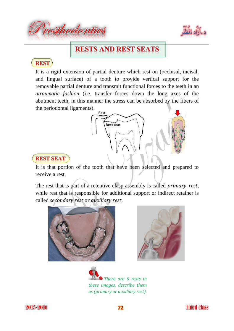
It is a rigid extension of partial denture which rest on (occlusal, incisal,
and lingual surface) of a tooth to provide vertical support for the
removable partial denture and transmit functional forces to the teeth in an
atraumatic fashion (i.e. transfer forces down the long axes of the
abutment teeth, in this manner the stress can be absorbed by the fibers of
the periodontal ligaments).
It is that portion of the tooth that have been selected and prepared to
receive a rest.
The rest that is part of a retentive clasp assembly is called primary rest,
while rest that is responsible for additional support or indirect retainer is
called secondary rest or auxiliary rest.
Rest
Rest seat
There are 6 rests in
these images, describe them
as (primary or auxiliary rest).
The primary purpose of the rest is to provide vertical support for the
partial denture that:
Maintains components in their planned positions.
If the retentive clasp is not supported, it will lose its ability to retain the
prosthesis in its intended position.
Maintains established occlusal relationships by preventing settling of the
denture.
Prevents impingement of soft tissue.
Directs and distributes occlusal loads to abutment teeth.
Serve as a reference point for evaluating the fit of the framework to the
teeth.
Prevent extrusion, tipping, or migration of the abutment teeth.
Acts along with its minor connector as an indirect retainer for a tooth-
tissue supported removable partial denture.
There are several points which should be put into consideration in
determination of the site and form of the rests.
Root form. 1-
Root length. 2-
Inclination of the tooth. 3-
Ratio of the length of the clinical crown to the alveolar support. 4-
(so named according where they seated on the
tooth surfaces)
Occlusal rest.
Lingual rest.
Incisal rest.
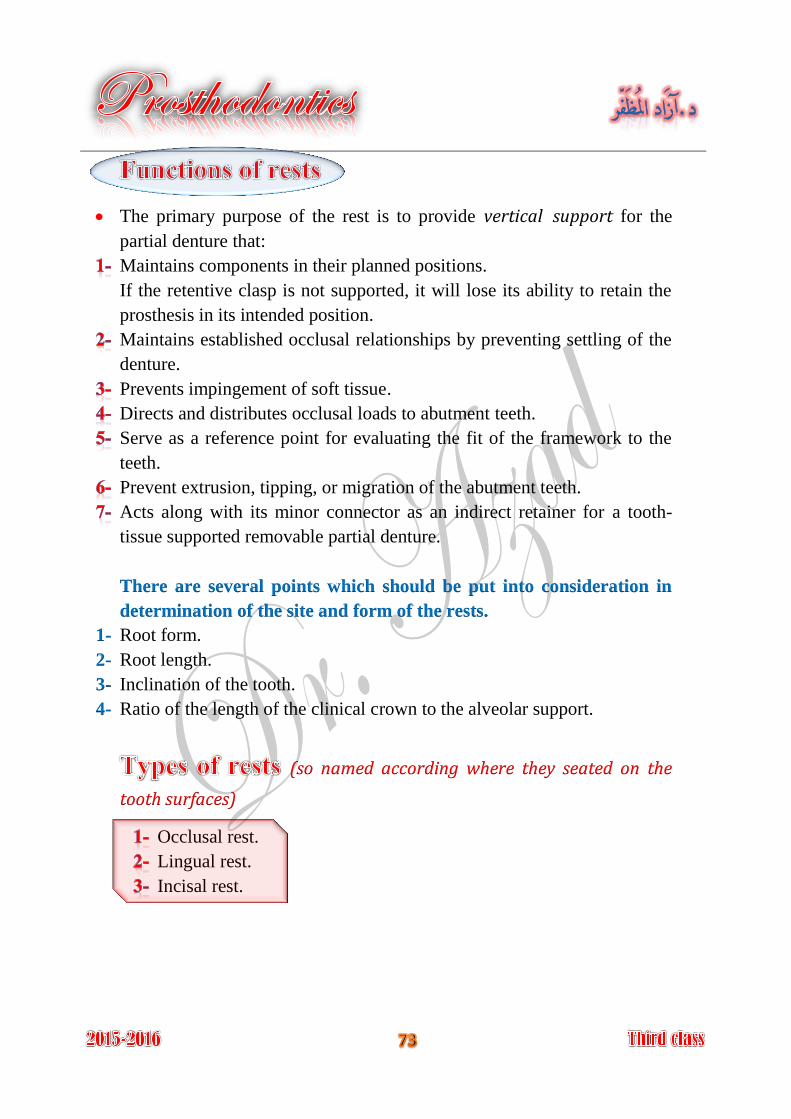
The outline form of an occlusal rest seat should be a rounded triangular 1-
shape, with the base of the triangle located at the marginal ridge and the
rounded apex directed toward the center of the occlusal surface.
It should be as long as it is wide; it should occupy 1\3 to 1\2 the 2-
mesiodistal diameter of the abutment, and 1\2 the buccolingual
intercuspal width. Rest seats of smaller dimensions do not provide an
adequate bulk of metal for rests.
The marginal ridge of the abutment tooth at the site of the rest seat must 3-
be lowered to permit a sufficient bulk of metal for strength and rigidity of
the rest and the minor connector. This means that a reduction of the
marginal ridge of approximately 1.5 mm is usually necessary.
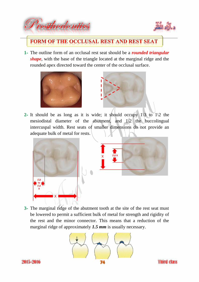
The floor of the occlusal rest seat should be apical to the marginal ridge 4-
and the occlusal surface and should be concave or spoon-shaped and
should function as ball-and-socket joint; this permits dissipation of
harmful lateral forces.
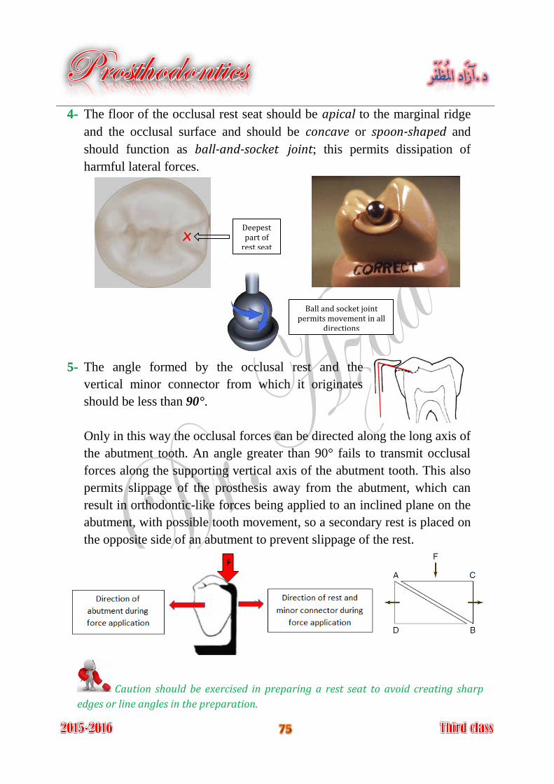
The angle formed by the occlusal rest and the 5-
vertical minor connector from which it originates
should be less than 90°.
Only in this way the occlusal forces can be directed along the long axis of
the abutment tooth. An angle greater than 90° fails to transmit occlusal
forces along the supporting vertical axis of the abutment tooth. This also
permits slippage of the prosthesis away from the abutment, which can
result in orthodontic-like forces being applied to an inclined plane on the
abutment, with possible tooth movement, so a secondary rest is placed on
the opposite side of an abutment to prevent slippage of the rest.
Deepest part of
rest seat
Caution should be exercised in preparing a rest seat to avoid creating sharp
edges or line angles in the preparation.
Ball and socket joint permits movement in all
directions
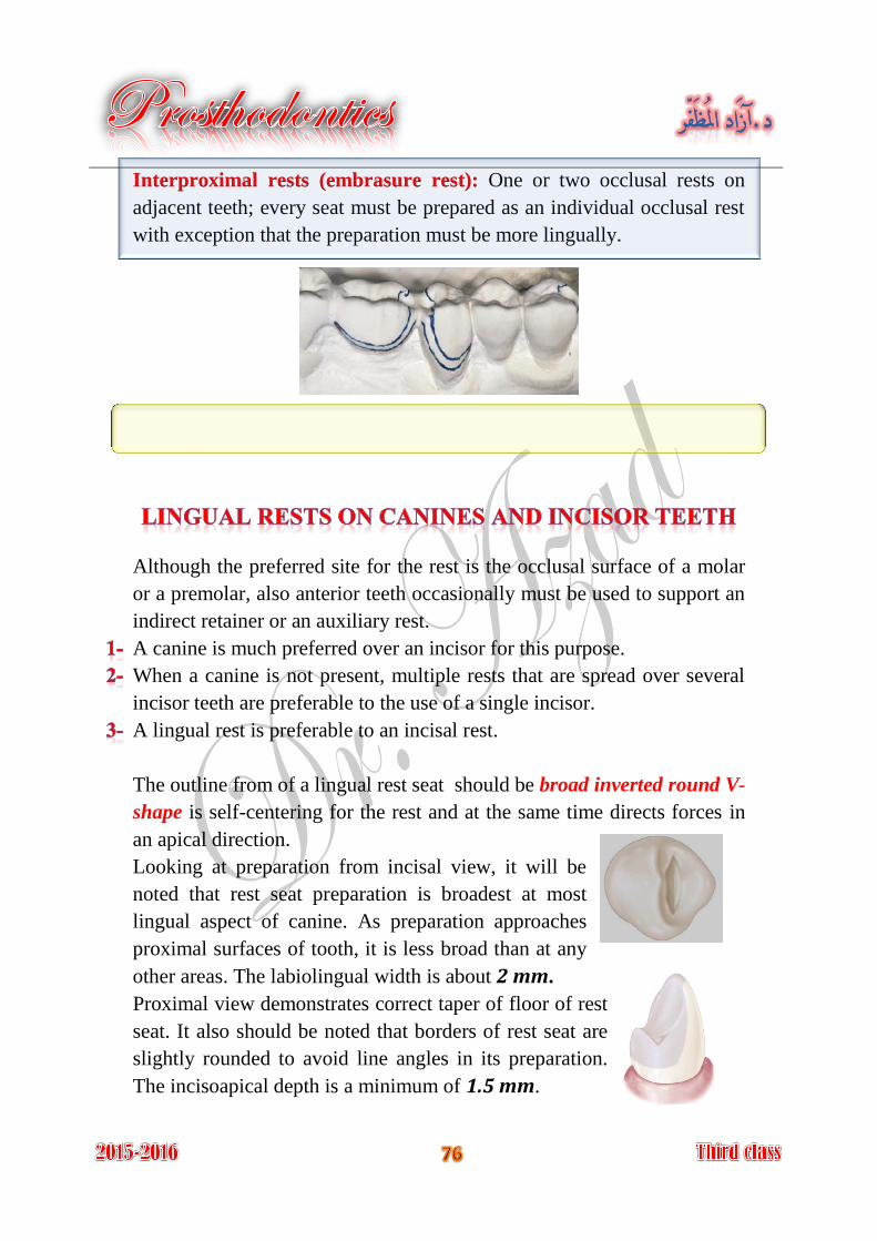
One or two occlusal rests on Interproximal rests (embrasure rest):
adjacent teeth; every seat must be prepared as an individual occlusal rest
with exception that the preparation must be more lingually.
Although the preferred site for the rest is the occlusal surface of a molar
or a premolar, also anterior teeth occasionally must be used to support an
indirect retainer or an auxiliary rest.
A canine is much preferred over an incisor for this purpose.
When a canine is not present, multiple rests that are spread over several
incisor teeth are preferable to the use of a single incisor.
A lingual rest is preferable to an incisal rest.
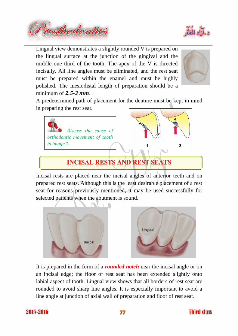
The outline from of a lingual rest seat should be broad inverted round V-
shape is self-centering for the rest and at the same time directs forces in
an apical direction.
Looking at preparation from incisal view, it will be
noted that rest seat preparation is broadest at most
lingual aspect of canine. As preparation approaches
proximal surfaces of tooth, it is less broad than at any
other areas. The labiolingual width is about 2 mm.
Proximal view demonstrates correct taper of floor of rest
seat. It also should be noted that borders of rest seat are
slightly rounded to avoid line angles in its preparation.
The incisoapical depth is a minimum of 1.5 mm.
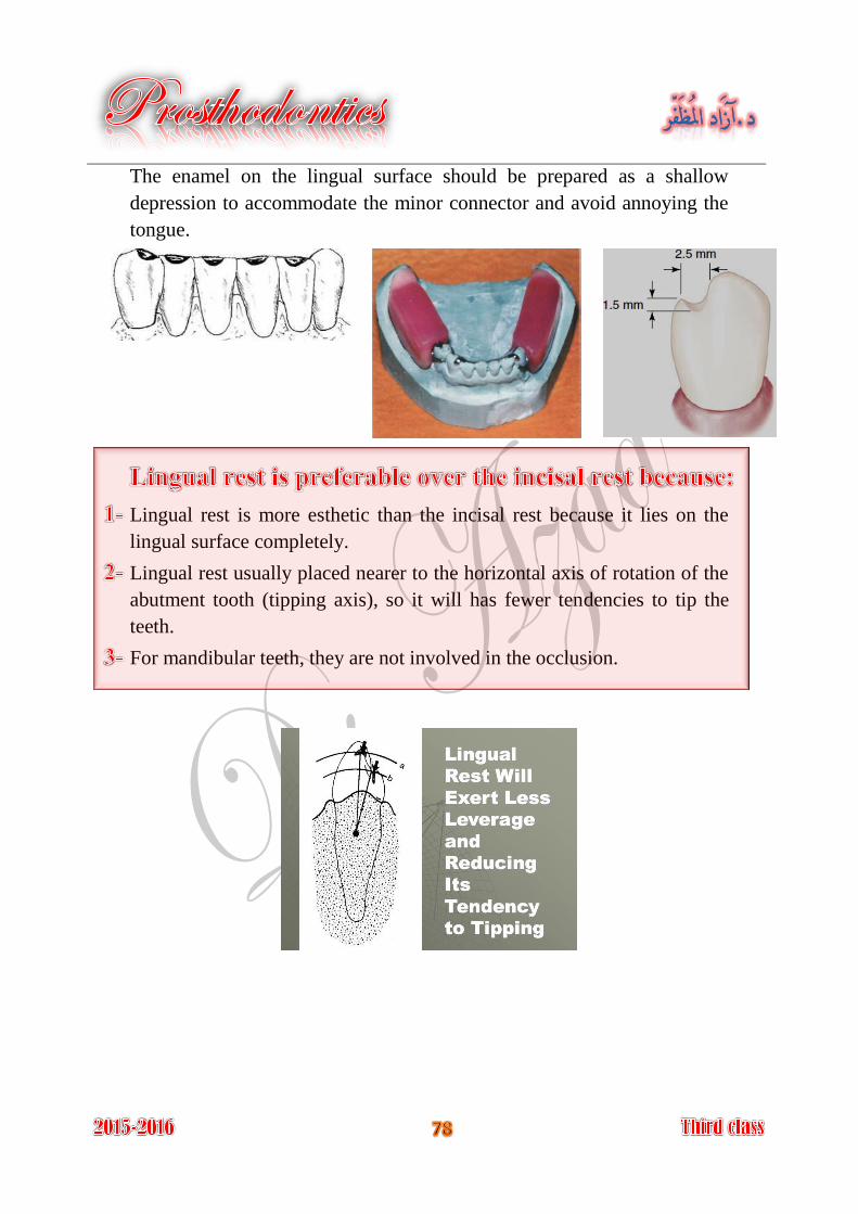
Lingual view demonstrates a slightly rounded V is prepared on
the lingual surface at the junction of the gingival and the
middle one third of the tooth. The apex of the V is directed
incisally. All line angles must be eliminated, and the rest seat
must be prepared within the enamel and must be highly
polished. The mesiodistal length of preparation should be a
minimum of 2.5-3 mm.
A predetermined path of placement for the denture must be kept in mind
in preparing the rest seat.
Incisal rests are placed near the incisal angles of anterior teeth and on
prepared rest seats. Although this is the least desirable placement of a rest
seat for reasons previously mentioned, it may be used successfully for
selected patients when the abutment is sound.
It is prepared in the form of a rounded notch near the incisal angle or on
an incisal edge; the floor of rest seat has been extended slightly onto
labial aspect of tooth. Lingual view shows that all borders of rest seat are
rounded to avoid sharp line angles. It is especially important to avoid a
line angle at junction of axial wall of preparation and floor of rest seat.
Discuss the cause of
orthodontic movement of tooth
in image 1.
Buccal
Lingual
The enamel on the lingual surface should be prepared as a shallow
depression to accommodate the minor connector and avoid annoying the
tongue.
Lingual rest is more esthetic than the incisal rest because it lies on the
lingual surface completely.
Lingual rest usually placed nearer to the horizontal axis of rotation of the
abutment tooth (tipping axis), so it will has fewer tendencies to tip the
teeth.
For mandibular teeth, they are not involved in the occlusion.
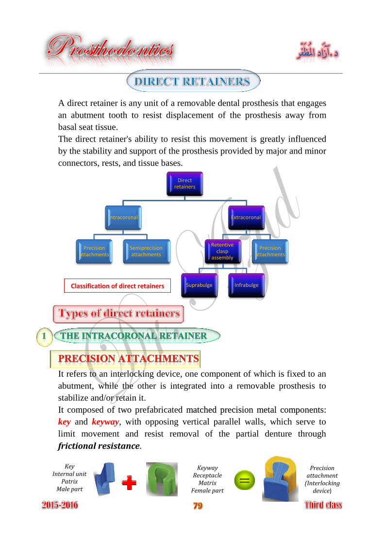
A direct retainer is any unit of a removable dental prosthesis that engages
an abutment tooth to resist displacement of the prosthesis away from
basal seat tissue.
The direct retainer's ability to resist this movement is greatly influenced
by the stability and support of the prosthesis provided by major and minor
connectors, rests, and tissue bases.
It refers to an interlocking device, one component of which is fixed to an
abutment, while the other is integrated into a removable prosthesis to
stabilize and/or retain it.
composed prefabricated It of two matched precision metal components:
key and keyway, with opposing vertical parallel walls, which serve to
limit movement and resist removal of the partial denture through
frictional resistance.
Direct retainers
Intracoronal
Precision attachments
Semiprecision attachments
Extracoronal
Retentive clasp
assembly
Suprabulge Infrabulge
Precision attachments
Classification of direct retainers
Key Internal unit
Patrix Male part
Keyway Receptacle
Matrix Female part
Precision attachment
(Interlocking device)
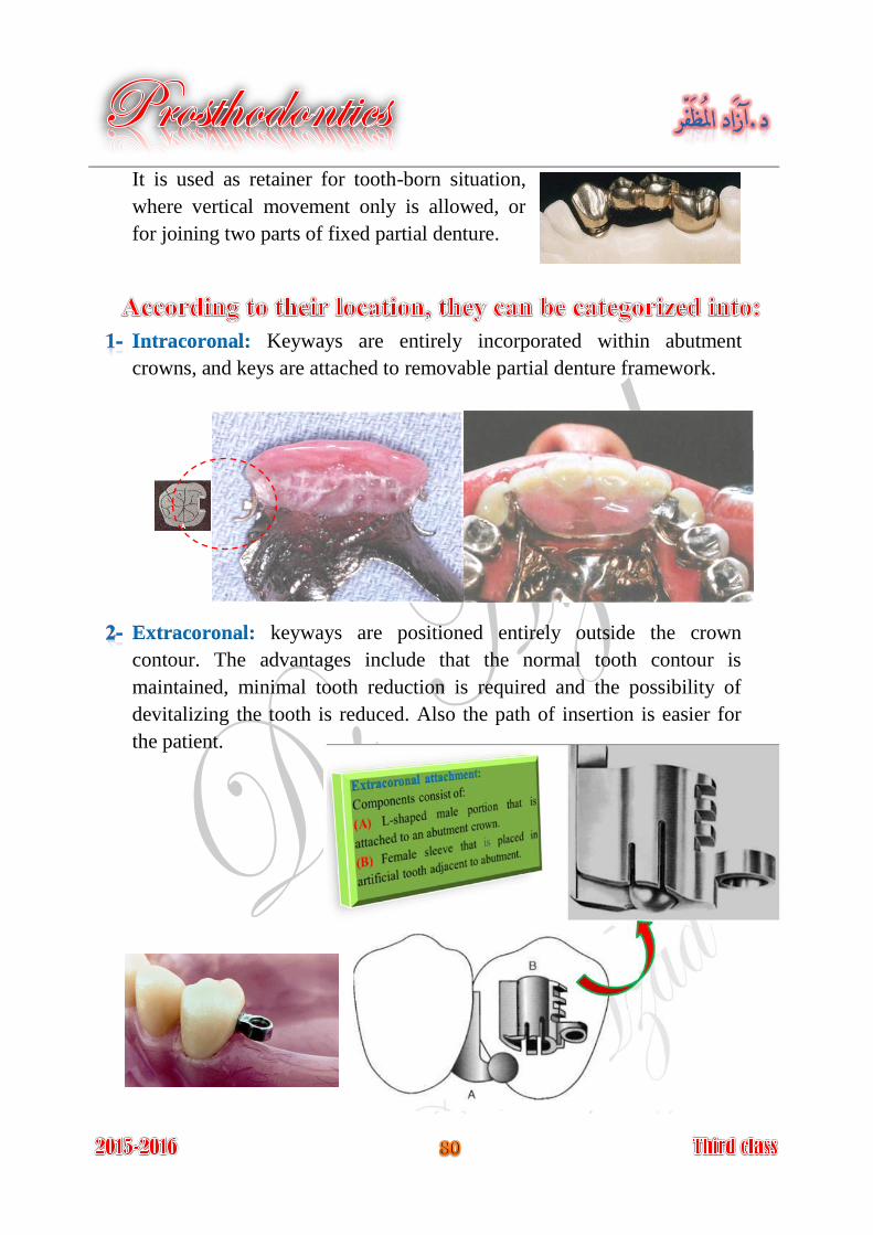
It is used as retainer for tooth-born situation,
where vertical movement only is allowed, or
for joining two parts of fixed partial denture.
Keyways are entirely incorporated within abutment Intracoronal:
crowns, and keys are attached to removable partial denture framework.
keyways are positioned entirely outside the crown Extracoronal:
contour. The advantages include that the normal tooth contour is
maintained, minimal tooth reduction is required and the possibility of
devitalizing the tooth is reduced. Also the path of insertion is easier for
the patient.
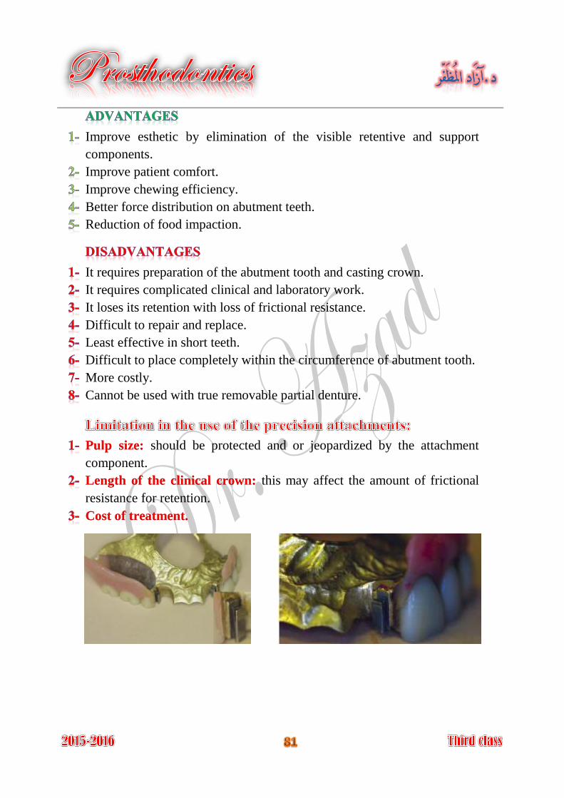
Improve esthetic by elimination of the visible retentive and support
components.
Improve patient comfort.
Improve chewing efficiency.
Better force distribution on abutment teeth.
Reduction of food impaction.
It requires preparation of the abutment tooth and casting crown.
It requires complicated clinical and laboratory work.
It loses its retention with loss of frictional resistance.
Difficult to repair and replace.
Least effective in short teeth.
Difficult to place completely within the circumference of abutment tooth.
More costly.
Cannot be used with true removable partial denture.
should be protected and or jeopardized by the attachment Pulp size:
component.
this may affect the amount of frictional Length of the clinical crown:
resistance for retention.
Cost of treatment.
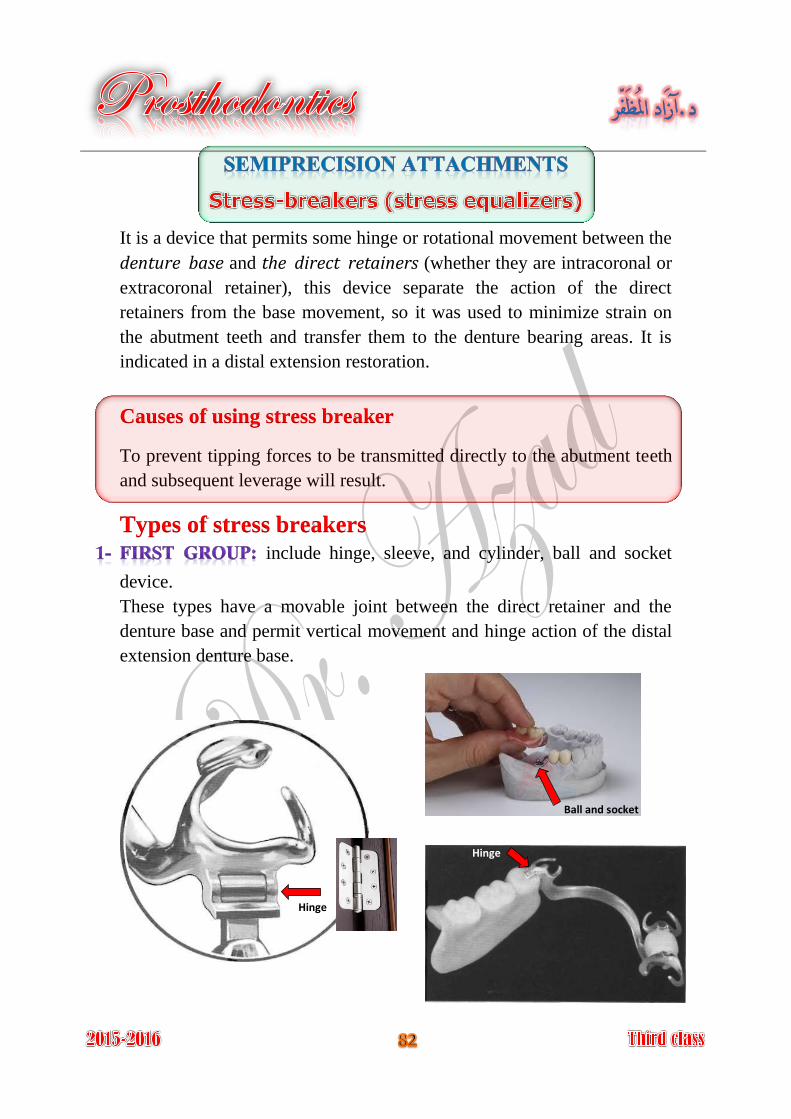
It is a device that permits some hinge or rotational movement between the
denture base and the direct retainers (whether they are intracoronal or
extracoronal retainer), this device separate the action of the direct
retainers from the base movement, so it was used to minimize strain on
the abutment teeth and transfer them to the denture bearing areas. It is
indicated in a distal extension restoration.
Causes of using stress breaker
To prevent tipping forces to be transmitted directly to the abutment teeth
and subsequent leverage will result.
Types of stress breakers include hinge, sleeve, and cylinder, ball and socket
device.
These types have a movable joint between the direct retainer and the
denture base and permit vertical movement and hinge action of the distal
extension denture base.
Ball and socket
Hinge
Hinge
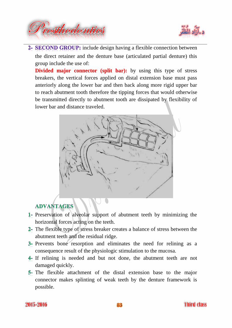
include design having a flexible connection between
the direct retainer and the denture base (articulated partial denture) this
group include the use of:
by using this type of stress Divided major connector (split bar):
breakers, the vertical forces applied on distal extension base must pass
anteriorly along the lower bar and then back along more rigid upper bar
to reach abutment tooth therefore the tipping forces that would otherwise
be transmitted directly to abutment tooth are dissipated by flexibility of
lower bar and distance traveled.
Preservation of alveolar support of abutment teeth by minimizing the
horizontal forces acting on the teeth.
The flexible type of stress breaker creates a balance of stress between the
abutment teeth and the residual ridge.
Prevents bone resorption and eliminates the need for relining as a
consequence result of the physiologic stimulation to the mucosa.
If relining is needed and but not done, the abutment teeth are not
damaged quickly.
The flexible attachment of the distal extension base to the major
connector makes splinting of weak teeth by the denture framework is
possible.
Lack of occlusal stability.
Not provide bracing for lateral forces.
Improper control of forces distribution between the dentulous and
edentulous areas.
The denture is more difficult to fabricate and therefore more costly.
Vertical and horizontal forces are concentrated on the residual ridge
resulting in excessive soreness and increased ridge resorption.
If relining is not done when needed excessive resorption of the residual
ridge may result.
The effectiveness of indirect retainers is reduced or eliminated.
Flexible connectors may be bent and fractured by careless handling and
by repeated flexing; more stress will be applied on the abutment.
Repair and maintenance of any stress breaker are difficult, costly, and
frequently required.
All mechanical devices those are free to move in the mouth in collect
debris and become unclean. And some split connector is used as stress
breaker pinch the underlying soft tissue or the tongue as they open and
close under function.
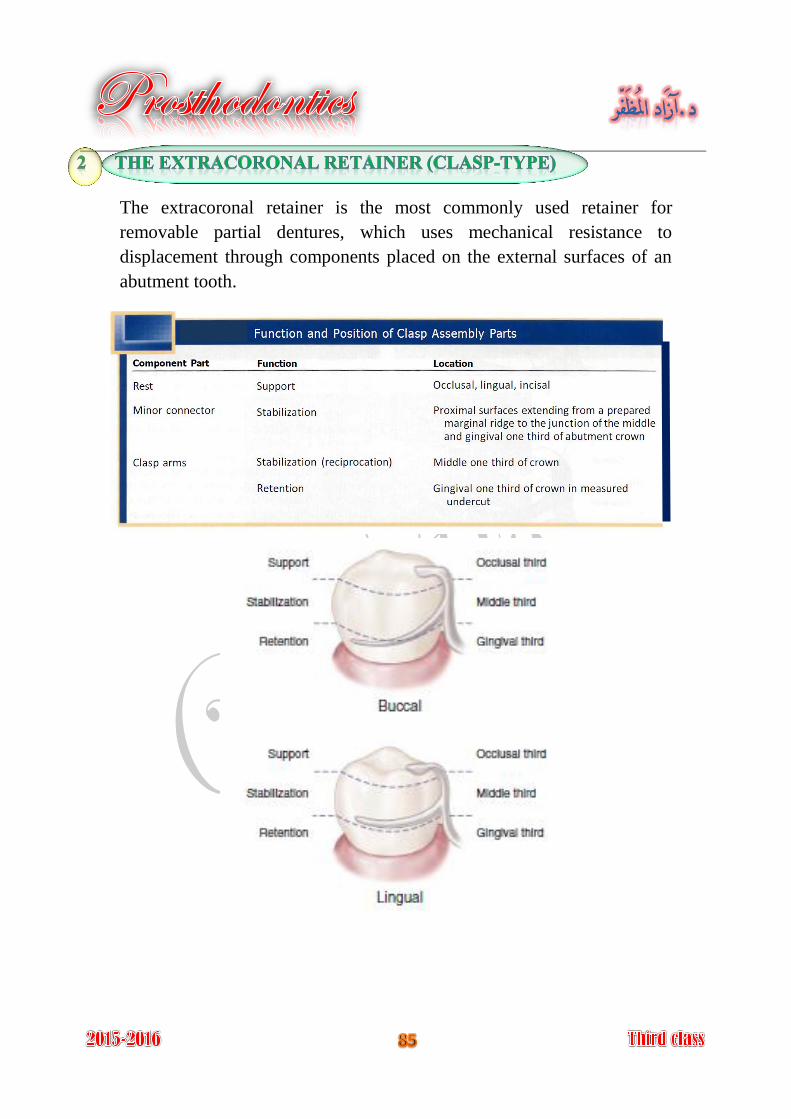
The extracoronal retainer is the most commonly used retainer for
removable partial dentures, which uses mechanical resistance to
displacement through components placed on the external surfaces of an
abutment tooth.
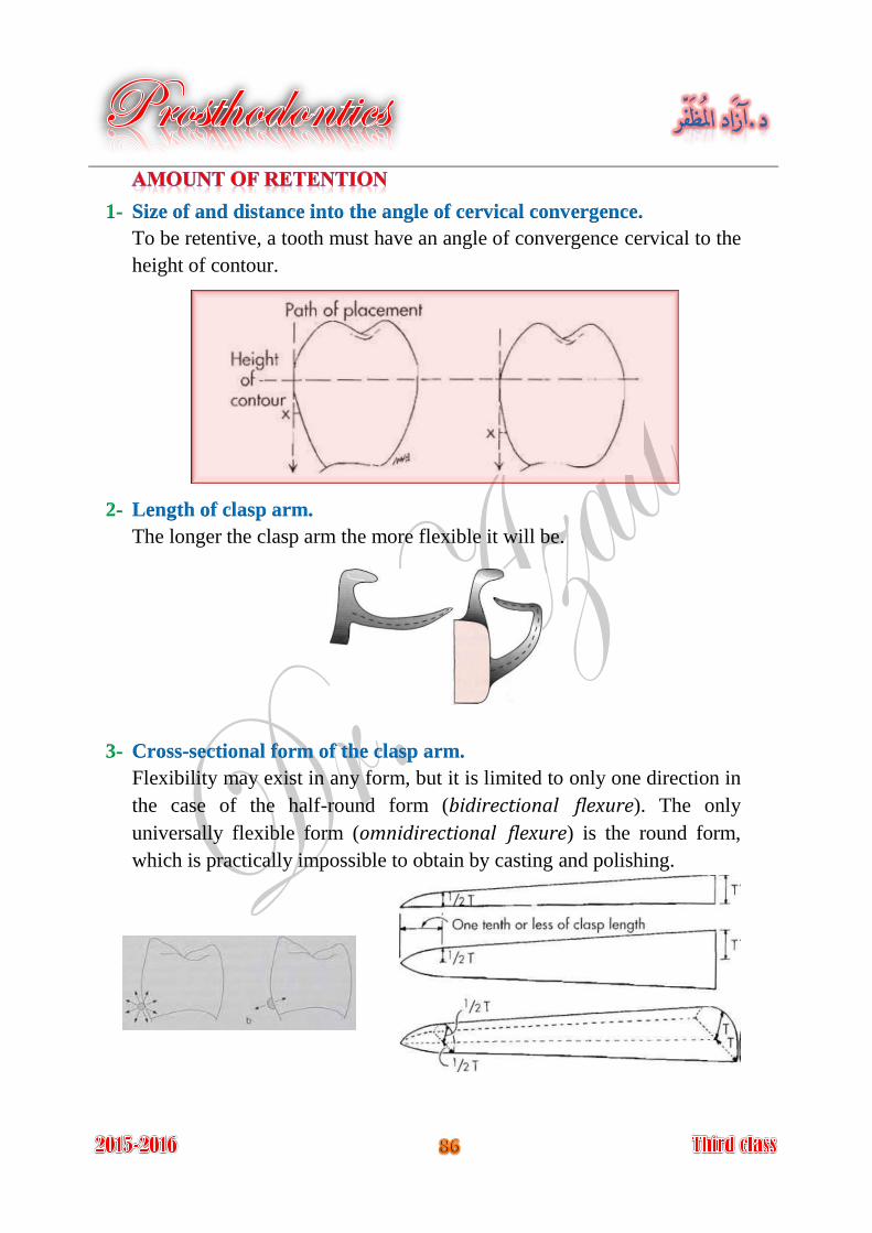
1- Size of and distance into the angle of cervical convergence.
To be retentive, a tooth must have an angle of convergence cervical to the
height of contour.
2- Length of clasp arm.
The longer the clasp arm the more flexible it will be.
3- Cross-sectional form of the clasp arm.
Flexibility may exist in any form, but it is limited to only one direction in
the case of the half-round form (bidirectional flexure). The only
universally flexible form (omnidirectional flexure) is the round form,
which is practically impossible to obtain by casting and polishing.
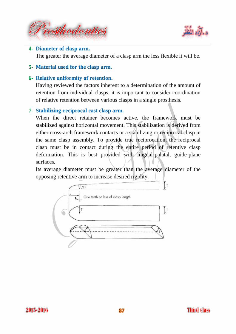
4- Diameter of clasp arm.
The greater the average diameter of a clasp arm the less flexible it will be.
5- Material used for the clasp arm.
6- Relative uniformity of retention.
Having reviewed the factors inherent to a determination of the amount of
retention from individual clasps, it is important to consider coordination
of relative retention between various clasps in a single prosthesis.
7- Stabilizing-reciprocal cast clasp arm.
When the direct retainer becomes active, the framework must be
stabilized against horizontal movement. This stabilization is derived from
either cross-arch framework contacts or a stabilizing or reciprocal clasp in
the same clasp assembly. To provide true reciprocation, the reciprocal
clasp must be in contact during the entire period of retentive clasp
deformation. This is best provided with lingual-palatal, guide-plane
surfaces.
Its average diameter must be greater than the average diameter of the
opposing retentive arm to increase desired rigidity.
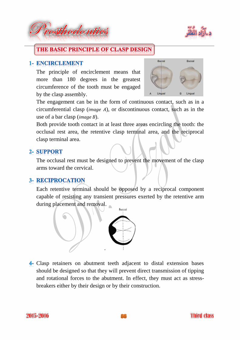
The principle of encirclement means that
more than 180 degrees in the greatest
circumference of the tooth must be engaged
by the clasp assembly.
The engagement can be in the form of continuous contact, such as in a
circumferential clasp (image A), or discontinuous contact, such as in the
use of a bar clasp (image B).
Both provide tooth contact in at least three areas encircling the tooth: the
occlusal rest area, the retentive clasp terminal area, and the reciprocal
clasp terminal area.
The occlusal rest must be designed to prevent the movement of the clasp
arms toward the cervical.
Each retentive terminal should be opposed by a reciprocal component
capable of resisting any transient pressures exerted by the retentive arm
during placement and removal.
.
Clasp retainers on abutment teeth adjacent to distal extension bases
should be designed so that they will prevent direct transmission of tipping
and rotational forces to the abutment. In effect, they must act as stress-
breakers either by their design or by their construction.
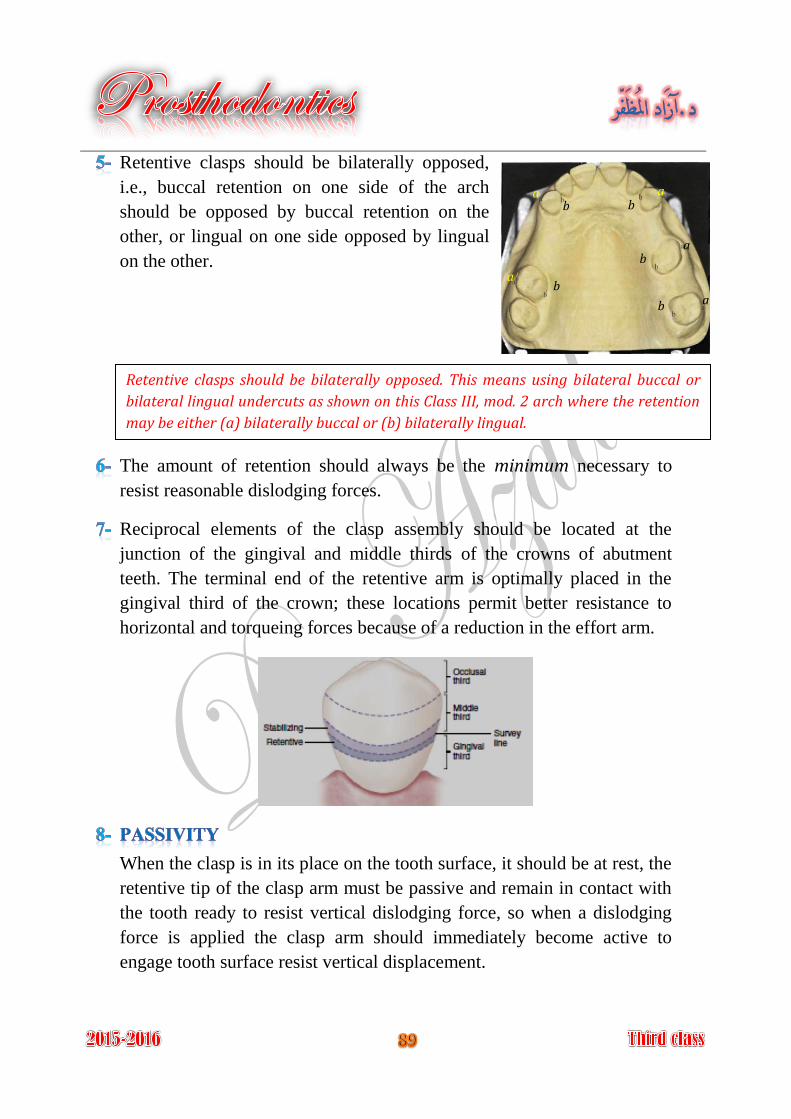
Retentive clasps should be bilaterally opposed,
i.e., buccal retention on one side of the arch
should be opposed by buccal retention on the
other, or lingual on one side opposed by lingual
on the other.
The amount of retention should always be the minimum necessary to
resist reasonable dislodging forces.
Reciprocal elements of the clasp assembly should be located at the
junction of the gingival and middle thirds of the crowns of abutment
teeth. The terminal end of the retentive arm is optimally placed in the
gingival third of the crown; these locations permit better resistance to
horizontal and torqueing forces because of a reduction in the effort arm.
When the clasp is in its place on the tooth surface, it should be at rest, the
retentive tip of the clasp arm must be passive and remain in contact with
the tooth ready to resist vertical dislodging force, so when a dislodging
force is applied the clasp arm should immediately become active to
engage tooth surface resist vertical displacement.
Retentive clasps should be bilaterally opposed. This means using bilateral buccal or
bilateral lingual undercuts as shown on this Class III, mod. 2 arch where the retention
may be either (a) bilaterally buccal or (b) bilaterally lingual.
a a
a
a
a
b b
b
b
b
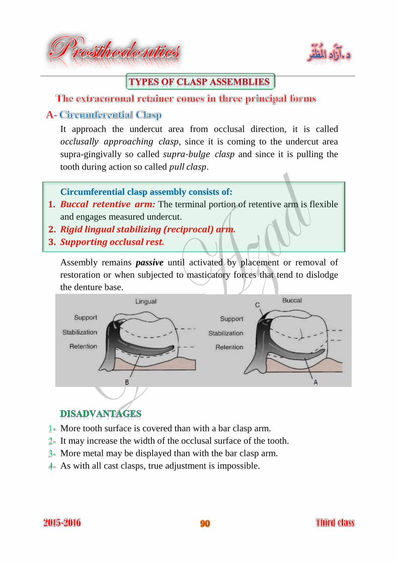
A-
It approach the undercut area from occlusal direction, it is called
occlusally approaching clasp, since it is coming to the undercut area
supra-gingivally so called supra-bulge clasp and since it is pulling the
tooth during action so called pull clasp.
Circumferential clasp assembly consists of:
Buccal retentive arm: The terminal portion of retentive arm is flexible 1.
and engages measured undercut.
Rigid lingual stabilizing (reciprocal) arm. 2.
Supporting occlusal rest. 3.
Assembly remains passive until activated by placement or removal of
restoration or when subjected to masticatory forces that tend to dislodge
the denture base.
More tooth surface is covered than with a bar clasp arm.
It may increase the width of the occlusal surface of the tooth.
More metal may be displayed than with the bar clasp arm.
As with all cast clasps, true adjustment is impossible.
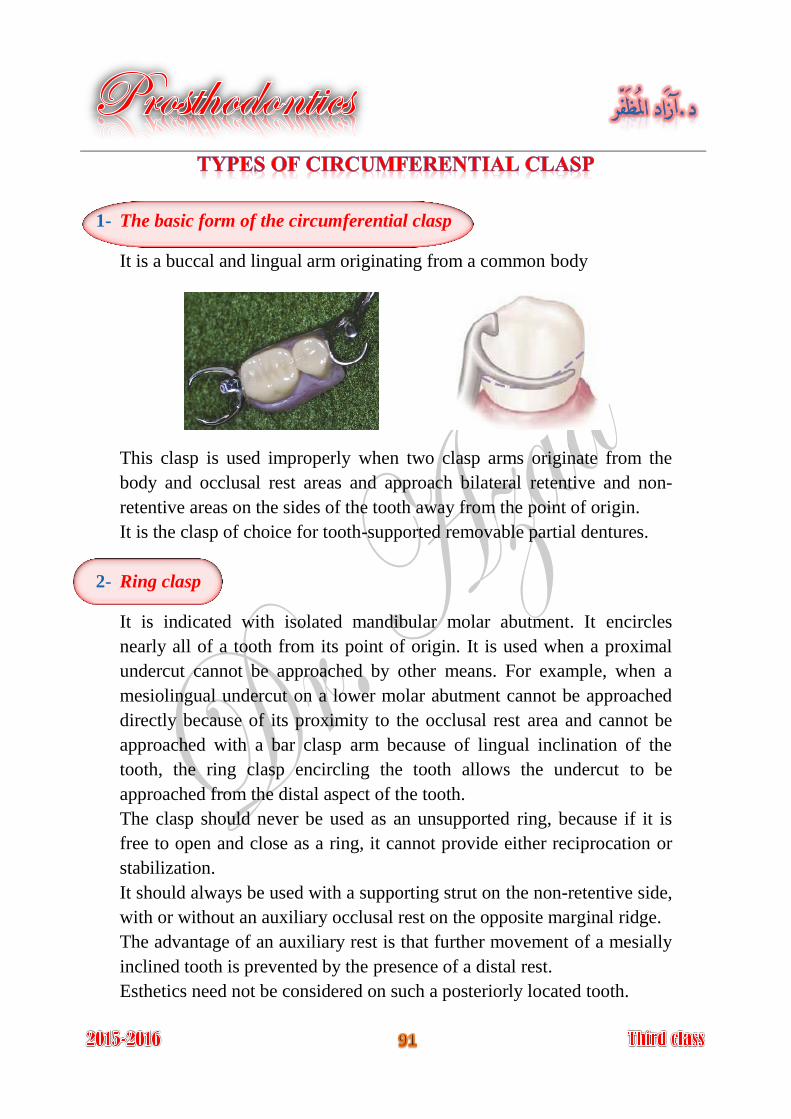
1- The basic form of the circumferential clasp
It is a buccal and lingual arm originating from a common body
This clasp is used improperly when two clasp arms originate from the
body and occlusal rest areas and approach bilateral retentive and non-
retentive areas on the sides of the tooth away from the point of origin.
It is the clasp of choice for tooth-supported removable partial dentures.
2- Ring clasp
It is indicated with isolated mandibular molar abutment. It encircles
nearly all of a tooth from its point of origin. It is used when a proximal
undercut cannot be approached by other means. For example, when a
mesiolingual undercut on a lower molar abutment cannot be approached
directly because of its proximity to the occlusal rest area and cannot be
approached with a bar clasp arm because of lingual inclination of the
tooth, the ring clasp encircling the tooth allows the undercut to be
approached from the distal aspect of the tooth.
The clasp should never be used as an unsupported ring, because if it is
free to open and close as a ring, it cannot provide either reciprocation or
stabilization.
It should always be used with a supporting strut on the non-retentive side,
with or without an auxiliary occlusal rest on the opposite marginal ridge.
The advantage of an auxiliary rest is that further movement of a mesially
inclined tooth is prevented by the presence of a distal rest.
Esthetics need not be considered on such a posteriorly located tooth.
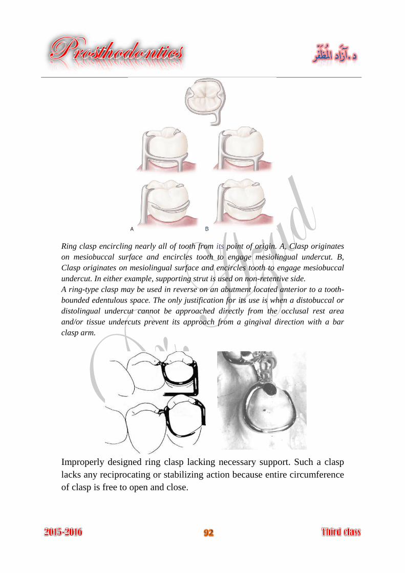
Ring clasp encircling nearly all of tooth from its point of origin. A, Clasp originates
on mesiobuccal surface and encircles tooth to engage mesiolingual undercut. B,
Clasp originates on mesiolingual surface and encircles tooth to engage mesiobuccal
undercut. In either example, supporting strut is used on non-retentive side.
A ring-type clasp may be used in reverse on an abutment located anterior to a tooth-
bounded edentulous space. The only justification for its use is when a distobuccal or
distolingual undercut cannot be approached directly from the occlusal rest area
and/or tissue undercuts prevent its approach from a gingival direction with a bar
clasp arm.
Improperly designed ring clasp lacking necessary support. Such a clasp
lacks any reciprocating or stabilizing action because entire circumference
of clasp is free to open and close.
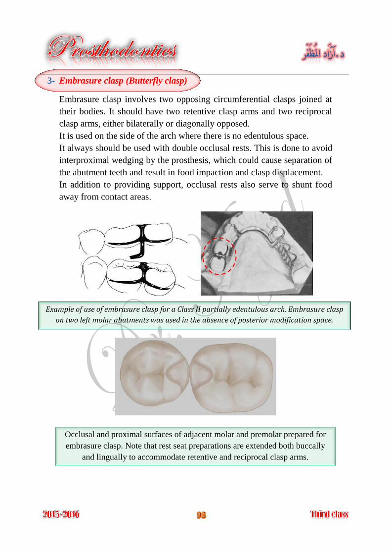
3- Embrasure clasp (Butterfly clasp)
Embrasure clasp involves two opposing circumferential clasps joined at
their bodies. It should have two retentive clasp arms and two reciprocal
clasp arms, either bilaterally or diagonally opposed.
It is used on the side of the arch where there is no edentulous space.
It always should be used with double occlusal rests. This is done to avoid
interproximal wedging by the prosthesis, which could cause separation of
the abutment teeth and result in food impaction and clasp displacement.
In addition to providing support, occlusal rests also serve to shunt food
away from contact areas.
Example of use of embrasure clasp for a Class II partially edentulous arch. Embrasure clasp
on two left molar abutments was used in the absence of posterior modification space.
Occlusal and proximal surfaces of adjacent molar and premolar prepared for
embrasure clasp. Note that rest seat preparations are extended both buccally
and lingually to accommodate retentive and reciprocal clasp arms.
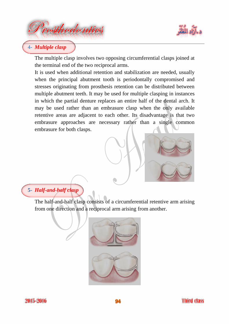
4- Multiple clasp
The multiple clasp involves two opposing circumferential clasps joined at
the terminal end of the two reciprocal arms.
It is used when additional retention and stabilization are needed, usually
when the principal abutment tooth is periodontally compromised and
stresses originating from prosthesis retention can be distributed between
multiple abutment teeth. It may be used for multiple clasping in instances
in which the partial denture replaces an entire half of the dental arch. It
may be used rather than an embrasure clasp when the only available
retentive areas are adjacent to each other. Its disadvantage is that two
embrasure approaches are necessary rather than a single common
embrasure for both clasps.
5- Half-and-half clasp
The half-and-half clasp consists of a circumferential retentive arm arising
from one direction and a reciprocal arm arising from another.
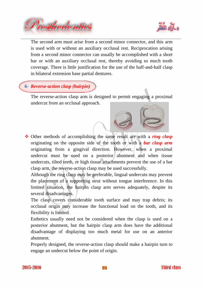
The second arm must arise from a second minor connector, and this arm
is used with or without an auxiliary occlusal rest. Reciprocation arising
from a second minor connector can usually be accomplished with a short
bar or with an auxiliary occlusal rest, thereby avoiding so much tooth
coverage. There is little justification for the use of the half-and-half clasp
in bilateral extension base partial dentures.
6- Reverse-action clasp (hairpin)
The reverse-action clasp arm is designed to permit engaging a proximal
undercut from an occlusal approach.
Other methods of accomplishing the same result are with a ring clasp
originating on the opposite side of the tooth or with a bar clasp arm
originating from a gingival direction. However, when a proximal
undercut must be used on a posterior abutment and when tissue
undercuts, tilted teeth, or high tissue attachments prevent the use of a bar
clasp arm, the reverse-action clasp may be used successfully.
Although the ring clasp may be preferable, lingual undercuts may prevent
the placement of a supporting strut without tongue interference. In this
limited situation, the hairpin clasp arm serves adequately, despite its
several disadvantages.
The clasp covers considerable tooth surface and may trap debris; its
occlusal origin may increase the functional load on the tooth, and its
flexibility is limited.
Esthetics usually need not be considered when the clasp is used on a
posterior abutment, but the hairpin clasp arm does have the additional
disadvantage of displaying too much metal for use on an anterior
abutment.
Properly designed, the reverse-action clasp should make a hairpin turn to
engage an undercut below the point of origin.
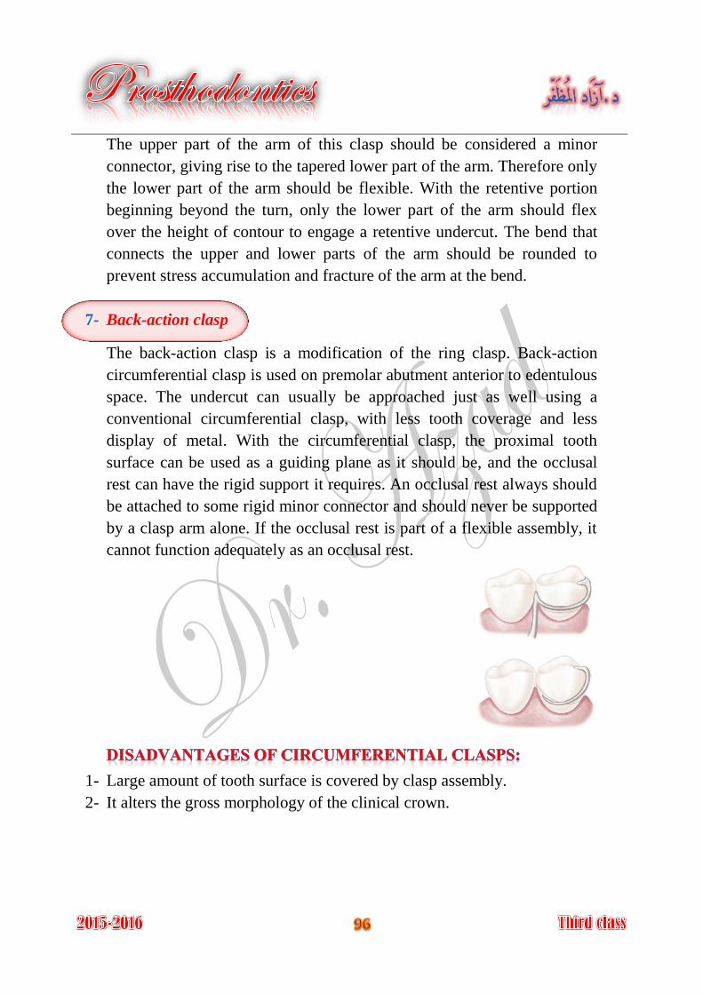
The upper part of the arm of this clasp should be considered a minor
connector, giving rise to the tapered lower part of the arm. Therefore only
the lower part of the arm should be flexible. With the retentive portion
beginning beyond the turn, only the lower part of the arm should flex
over the height of contour to engage a retentive undercut. The bend that
connects the upper and lower parts of the arm should be rounded to
prevent stress accumulation and fracture of the arm at the bend.
7- Back-action clasp
The back-action clasp is a modification of the ring clasp. Back-action
circumferential clasp is used on premolar abutment anterior to edentulous
space. The undercut can usually be approached just as well using a
conventional circumferential clasp, with less tooth coverage and less
display of metal. With the circumferential clasp, the proximal tooth
surface can be used as a guiding plane as it should be, and the occlusal
rest can have the rigid support it requires. An occlusal rest always should
be attached to some rigid minor connector and should never be supported
by a clasp arm alone. If the occlusal rest is part of a flexible assembly, it
cannot function adequately as an occlusal rest.
1- Large amount of tooth surface is covered by clasp assembly.
2- It alters the gross morphology of the clinical crown.
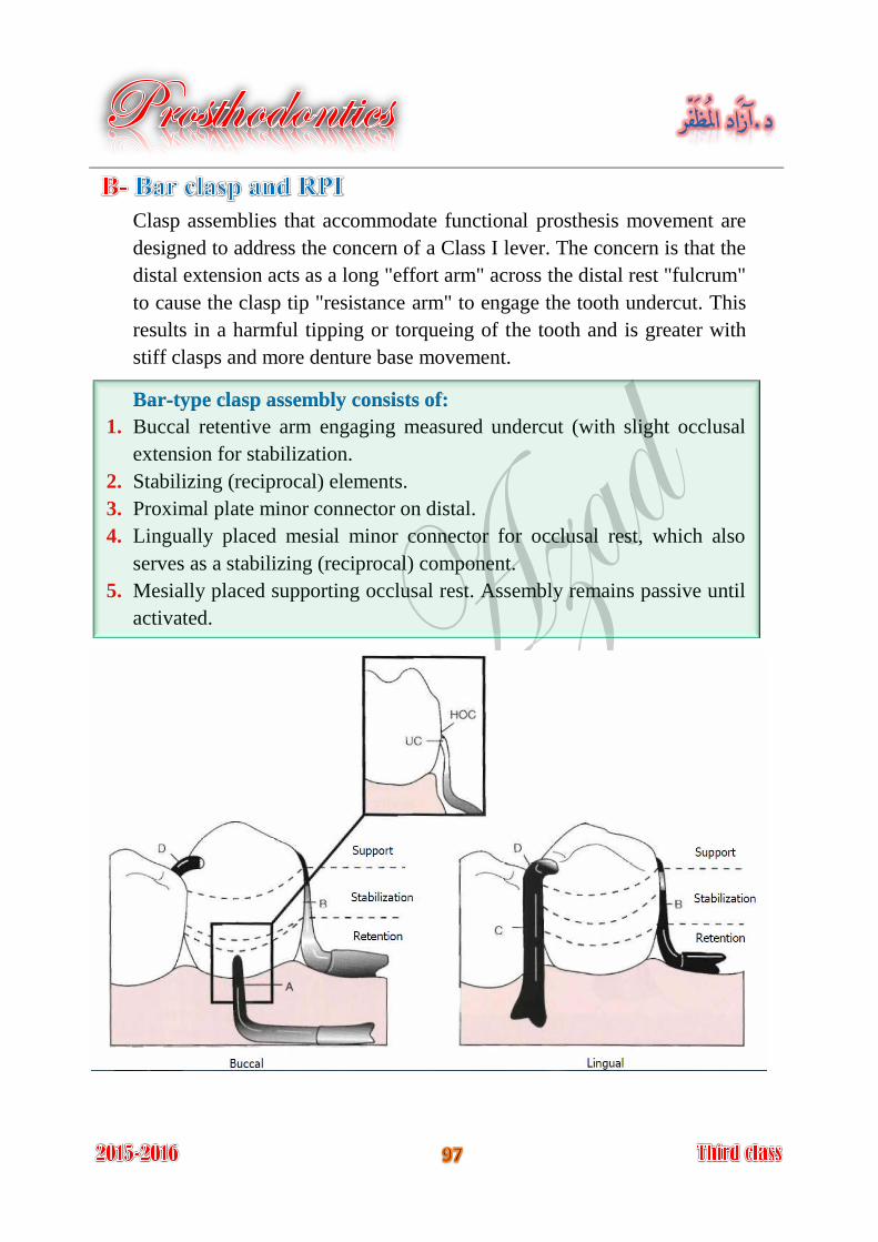
Clasp assemblies that accommodate functional prosthesis movement are
designed to address the concern of a Class I lever. The concern is that the
distal extension acts as a long "effort arm" across the distal rest "fulcrum"
to cause the clasp tip "resistance arm" to engage the tooth undercut. This
results in a harmful tipping or torqueing of the tooth and is greater with
stiff clasps and more denture base movement.
Bar-type clasp assembly consists of:
1. Buccal retentive arm engaging measured undercut (with slight occlusal
extension for stabilization.
2. Stabilizing (reciprocal) elements.
3. Proximal plate minor connector on distal.
4. Lingually placed mesial minor connector for occlusal rest, which also
serves as a stabilizing (reciprocal) component.
5. Mesially placed supporting occlusal rest. Assembly remains passive until
activated.
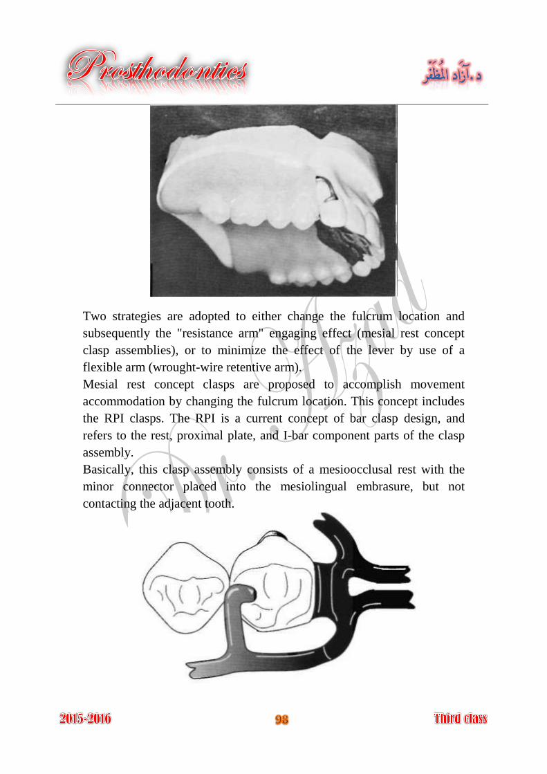
Two strategies are adopted to either change the fulcrum location and
subsequently the "resistance arm" engaging effect (mesial rest concept
clasp assemblies), or to minimize the effect of the lever by use of a
flexible arm (wrought-wire retentive arm).
Mesial rest concept clasps are proposed to accomplish movement
accommodation by changing the fulcrum location. This concept includes
the RPI clasps. The RPI is a current concept of bar clasp design, and
refers to the rest, proximal plate, and I-bar component parts of the clasp
assembly.
Basically, this clasp assembly consists of a mesioocclusal rest with the
minor connector placed into the mesiolingual embrasure, but not
contacting the adjacent tooth.
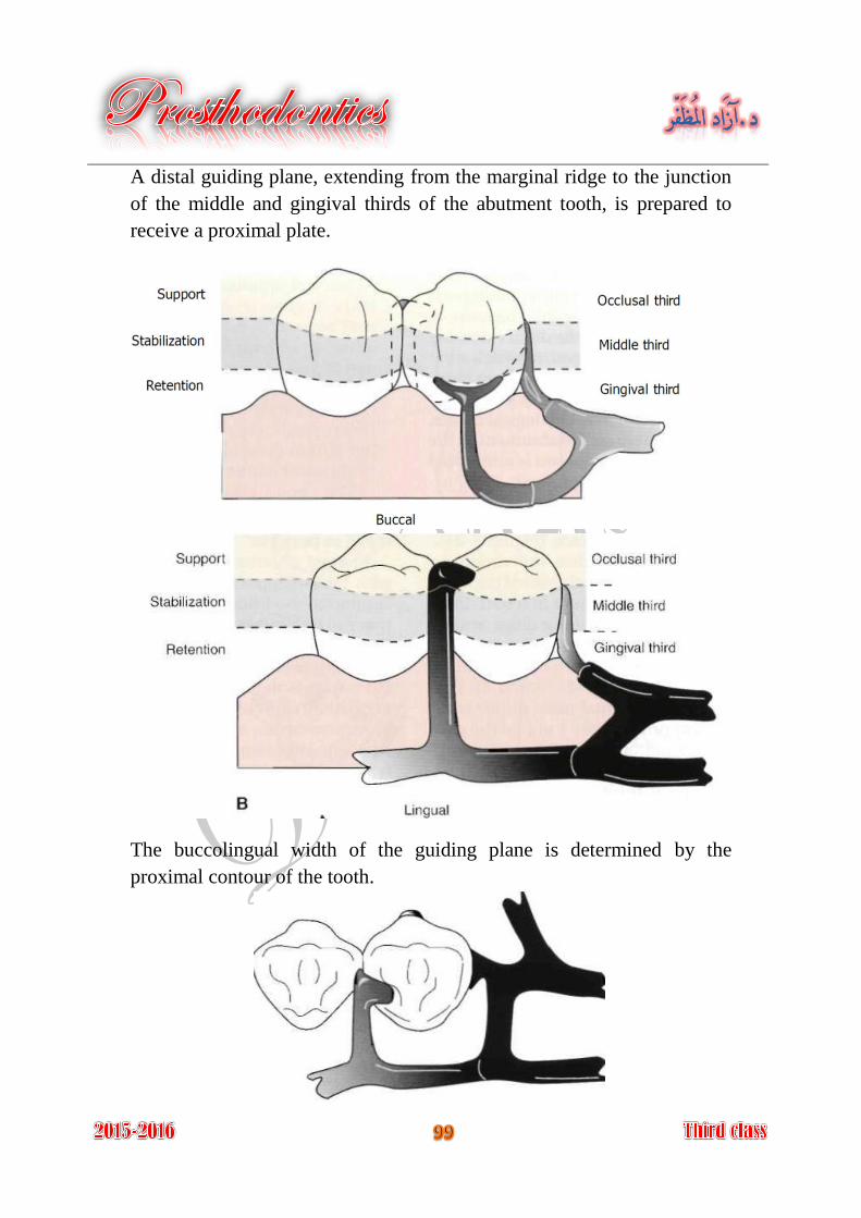
A distal guiding plane, extending from the marginal ridge to the junction
of the middle and gingival thirds of the abutment tooth, is prepared to
receive a proximal plate.
The buccolingual width of the guiding plane is determined by the
proximal contour of the tooth.
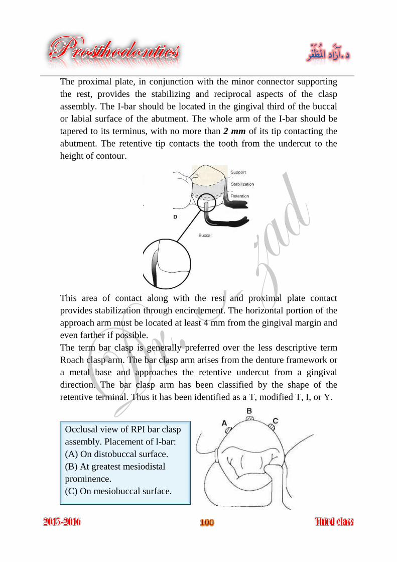
The proximal plate, in conjunction with the minor connector supporting
the rest, provides the stabilizing and reciprocal aspects of the clasp
assembly. The I-bar should be located in the gingival third of the buccal
or labial surface of the abutment. The whole arm of the I-bar should be
tapered to its terminus, with no more than 2 mm of its tip contacting the
abutment. The retentive tip contacts the tooth from the undercut to the
height of contour.
This area of contact along with the rest and proximal plate contact
provides stabilization through encirclement. The horizontal portion of the
approach arm must be located at least 4 mm from the gingival margin and
even farther if possible.
The term bar clasp is generally preferred over the less descriptive term
Roach clasp arm. The bar clasp arm arises from the denture framework or
a metal base and approaches the retentive undercut from a gingival
direction. The bar clasp arm has been classified by the shape of the
retentive terminal. Thus it has been identified as a T, modified T, I, or Y.
Occlusal view of RPI bar clasp
assembly. Placement of l-bar:
(A) On distobuccal surface.
(B) At greatest mesiodistal
prominence.
(C) On mesiobuccal surface.
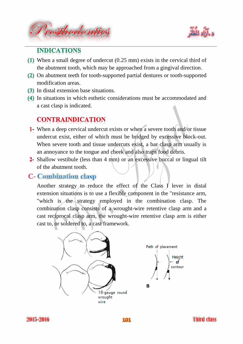
When a small degree of undercut (0.25 mm) exists in the cervical third of
the abutment tooth, which may be approached from a gingival direction.
On abutment teeth for tooth-supported partial dentures or tooth-supported
modification areas.
In distal extension base situations.
In situations in which esthetic considerations must be accommodated and
a cast clasp is indicated.
When a deep cervical undercut exists or when a severe tooth and/or tissue
undercut exist, either of which must be bridged by excessive block-out.
When severe tooth and tissue undercuts exist, a bar clasp arm usually is
an annoyance to the tongue and cheek and also traps food debris.
Shallow vestibule (less than 4 mm) or an excessive buccal or lingual tilt
of the abutment tooth.
C-
Another strategy to reduce the effect of the Class I lever in distal
extension situations is to use a flexible component in the "resistance arm,
"which is the strategy employed in the combination clasp. The
combination clasp consists of a wrought-wire retentive clasp arm and a
cast reciprocal clasp arm, the wrought-wire retentive clasp arm is either
cast to, or soldered to, a cast framework.
On an abutment tooth adjacent to a distal extension base where only a
mesial undercut exists on the abutment or where a large tissue undercut
contraindicates a bar-type retainer, to minimize the effects of first-class
lever system.
When maximum flexibility is desirable, such as on an abutment tooth
adjacent to a distal extension base or on a weak abutment when a bar-type
direct retainer is contraindicated.
Its adjustability when precise retentive requirements are unpredictable
and later adjustment to increase or decrease retention may be necessary.
Its esthetic advantage over cast clasps.
Flexibility, adjustability, and appearance of the wrought-wire retentive
arm.
Wrought-wire retentive arm makes only line contact with abutment tooth,
rather than broader contact of cast clasp.
Wrought in structure, it may be used in smaller diameters than a cast
clasp, with less danger of fracture.
Because it is round, light is reflected in such a manner that the display of
metal is less noticeable than with the broader surfaces of a cast clasp.
A less likely occurrence of fatigue failures in service with the tapered
wrought-wire retentive arm versus the cast.
Tapered, round wrought wire clasp arm may act somewhat as a stress
breaker between denture base and the abutment teeth.
It involves extra steps in fabrication, particularly when high-fusing
chromium alloys are used.
It may be distorted by careless handling on the part of the patient.
Because it is bent by hand, it may be less accurately adapted to the tooth
and therefore provide less stabilization in the suprabulge portion.
It may distort with function and not engage the tooth.
Fracture at joining point because of recrystallization of soldering metal.
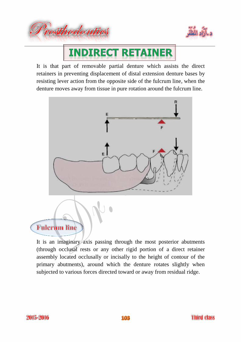
It is that part of removable partial denture which assists the direct
retainers in preventing displacement of distal extension denture bases by
resisting lever action from the opposite side of the fulcrum line, when the
denture moves away from tissue in pure rotation around the fulcrum line.
It is an imaginary axis passing through the most posterior abutments
(through occlusal rests or any other rigid portion of a direct retainer
assembly located occlusally or incisally to the height of contour of the
primary abutments), around which the denture rotates slightly when
subjected to various forces directed toward or away from residual ridge.
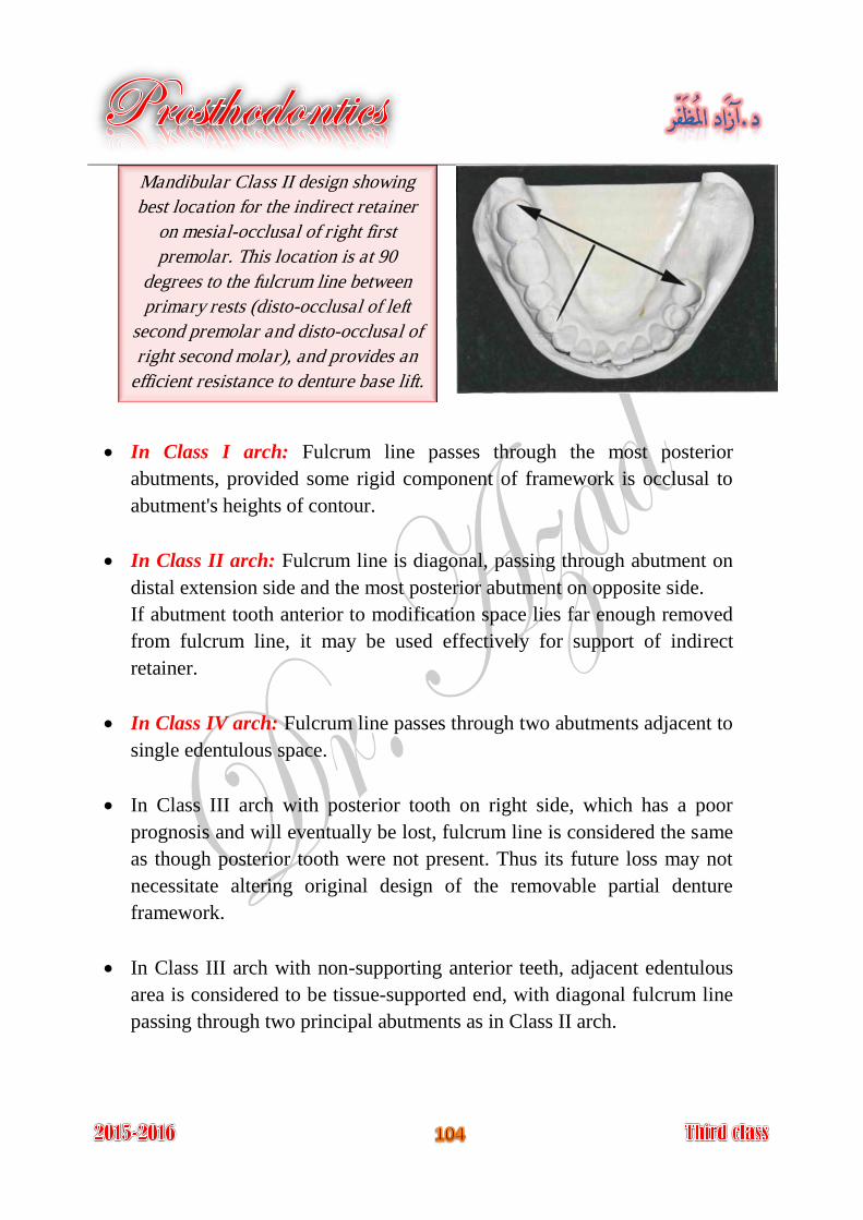
In Class I arch: Fulcrum line passes through the most posterior
abutments, provided some rigid component of framework is occlusal to
abutment's heights of contour.
In Class II arch: Fulcrum line is diagonal, passing through abutment on
distal extension side and the most posterior abutment on opposite side.
If abutment tooth anterior to modification space lies far enough removed
from fulcrum line, it may be used effectively for support of indirect
retainer.
In Class IV arch: Fulcrum line passes through two abutments adjacent to
single edentulous space.
In Class III arch with posterior tooth on right side, which has a poor
prognosis and will eventually be lost, fulcrum line is considered the same
as though posterior tooth were not present. Thus its future loss may not
necessitate altering original design of the removable partial denture
framework.
In Class III arch with non-supporting anterior teeth, adjacent edentulous
area is considered to be tissue-supported end, with diagonal fulcrum line
passing through two principal abutments as in Class II arch.
Mandibular Class II design showing
best location for the indirect retainer
on mesial-occlusal of right first
premolar. This location is at 90
degrees to the fulcrum line between
primary rests (disto-occlusal of left
second premolar and disto-occlusal of
right second molar), and provides an
efficient resistance to denture base lift.
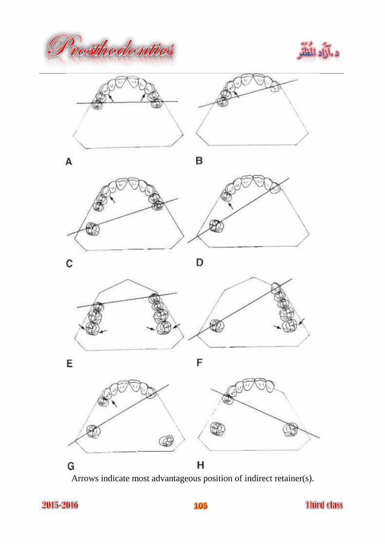
Arrows indicate most advantageous position of indirect retainer(s).
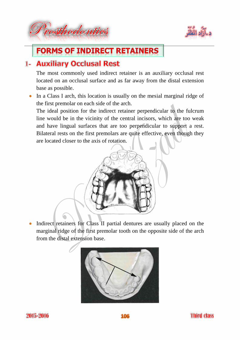
The most commonly used indirect retainer is an auxiliary occlusal rest
located on an occlusal surface and as far away from the distal extension
base as possible.
In a Class I arch, this location is usually on the mesial marginal ridge of
the first premolar on each side of the arch.
The ideal position for the indirect retainer perpendicular to the fulcrum
line would be in the vicinity of the central incisors, which are too weak
and have lingual surfaces that are too perpendicular to support a rest.
Bilateral rests on the first premolars are quite effective, even though they
are located closer to the axis of rotation.
Indirect retainers for Class II partial dentures are usually placed on the
marginal ridge of the first premolar tooth on the opposite side of the arch
from the distal extension base.
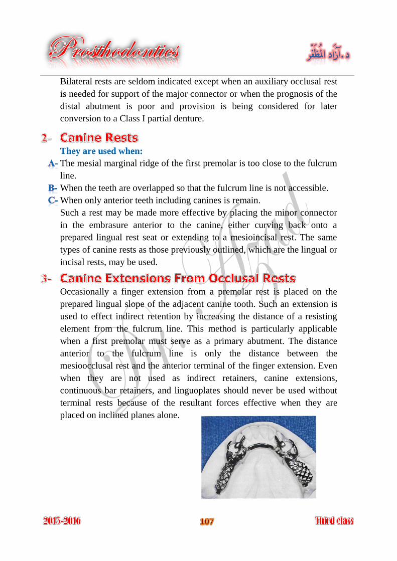
Bilateral rests are seldom indicated except when an auxiliary occlusal rest
is needed for support of the major connector or when the prognosis of the
distal abutment is poor and provision is being considered for later
conversion to a Class I partial denture.
They are used when:
The mesial marginal ridge of the first premolar is too close to the fulcrum
line.
When the teeth are overlapped so that the fulcrum line is not accessible.
When only anterior teeth including canines is remain.
Such a rest may be made more effective by placing the minor connector
in the embrasure anterior to the canine, either curving back onto a
prepared lingual rest seat or extending to a mesioincisal rest. The same
types of canine rests as those previously outlined, which are the lingual or
incisal rests, may be used.
Occasionally a finger extension from a premolar rest is placed on the
prepared lingual slope of the adjacent canine tooth. Such an extension is
used to effect indirect retention by increasing the distance of a resisting
element from the fulcrum line. This method is particularly applicable
when a first premolar must serve as a primary abutment. The distance
anterior to the fulcrum line is only the distance between the
mesioocclusal rest and the anterior terminal of the finger extension. Even
when they are not used as indirect retainers, canine extensions,
continuous bar retainers, and linguoplates should never be used without
terminal rests because of the resultant forces effective when they are
placed on inclined planes alone.
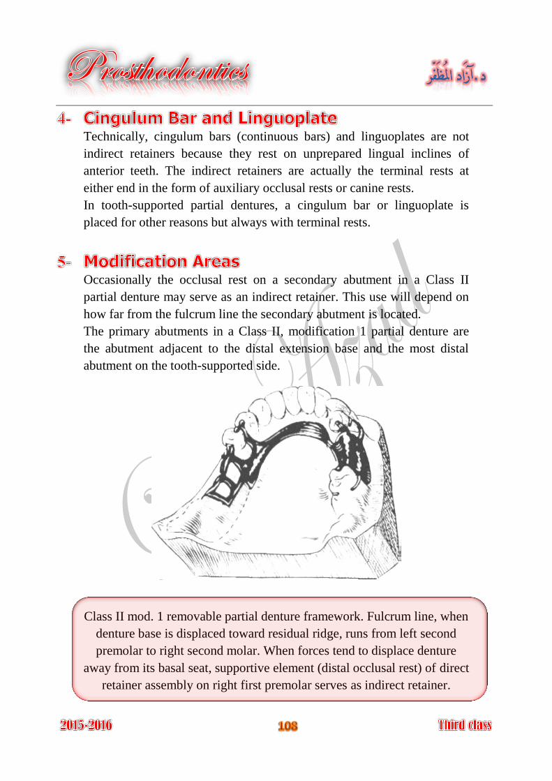
Technically, cingulum bars (continuous bars) and linguoplates are not
indirect retainers because they rest on unprepared lingual inclines of
anterior teeth. The indirect retainers are actually the terminal rests at
either end in the form of auxiliary occlusal rests or canine rests.
In tooth-supported partial dentures, a cingulum bar or linguoplate is
placed for other reasons but always with terminal rests.
Occasionally the occlusal rest on a secondary abutment in a Class II
partial denture may serve as an indirect retainer. This use will depend on
how far from the fulcrum line the secondary abutment is located.
The primary abutments in a Class II, modification 1 partial denture are
the abutment adjacent to the distal extension base and the most distal
abutment on the tooth-supported side.
Class II mod. 1 removable partial denture framework. Fulcrum line, when
denture base is displaced toward residual ridge, runs from left second
premolar to right second molar. When forces tend to displace denture
away from its basal seat, supportive element (distal occlusal rest) of direct
retainer assembly on right first premolar serves as indirect retainer.
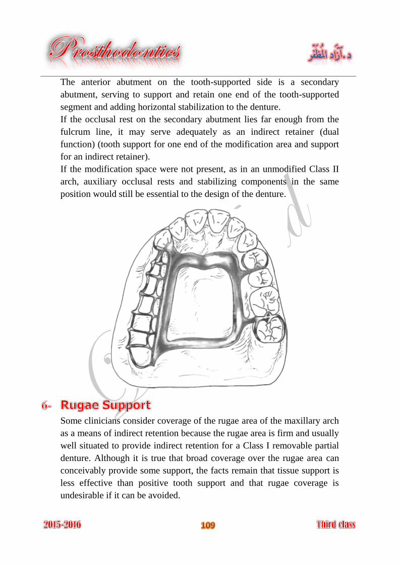
The anterior abutment on the tooth-supported side is a secondary
abutment, serving to support and retain one end of the tooth-supported
segment and adding horizontal stabilization to the denture.
If the occlusal rest on the secondary abutment lies far enough from the
fulcrum line, it may serve adequately as an indirect retainer (dual
function) (tooth support for one end of the modification area and support
for an indirect retainer).
If the modification space were not present, as in an unmodified Class II
arch, auxiliary occlusal rests and stabilizing components in the same
position would still be essential to the design of the denture.
Some clinicians consider coverage of the rugae area of the maxillary arch
as a means of indirect retention because the rugae area is firm and usually
well situated to provide indirect retention for a Class I removable partial
denture. Although it is true that broad coverage over the rugae area can
conceivably provide some support, the facts remain that tissue support is
less effective than positive tooth support and that rugae coverage is
undesirable if it can be avoided.
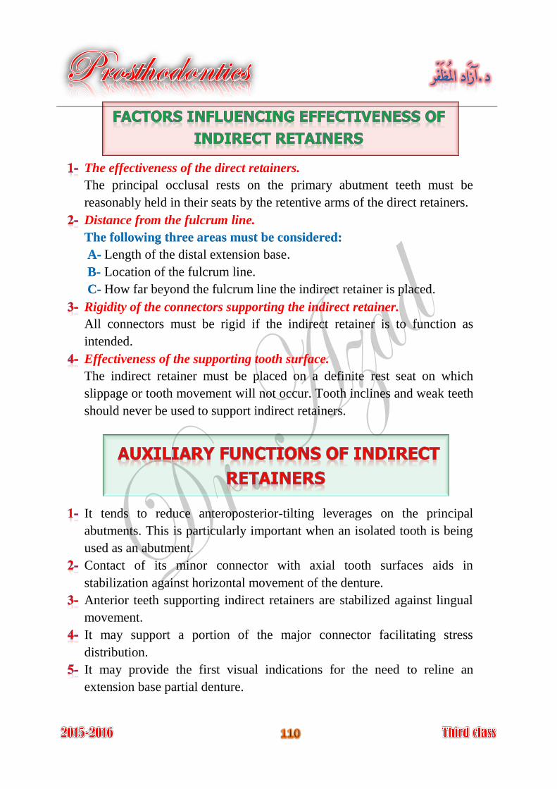
The effectiveness of the direct retainers.
The principal occlusal rests on the primary abutment teeth must be
reasonably held in their seats by the retentive arms of the direct retainers.
Distance from the fulcrum line.
The following three areas must be considered:
Length of the distal extension base. A-
Location of the fulcrum line. B-
How far beyond the fulcrum line the indirect retainer is placed. C-
Rigidity of the connectors supporting the indirect retainer.
All connectors must be rigid if the indirect retainer is to function as
intended.
Effectiveness of the supporting tooth surface. The indirect retainer must be placed on a definite rest seat on which
slippage or tooth movement will not occur. Tooth inclines and weak teeth
should never be used to support indirect retainers.
It tends to reduce anteroposterior-tilting leverages on the principal
abutments. This is particularly important when an isolated tooth is being
used as an abutment. Contact of its minor connector with axial tooth surfaces aids in
stabilization against horizontal movement of the denture. Anterior teeth supporting indirect retainers are stabilized against lingual
movement. It may support a portion of the major connector facilitating stress
distribution.
It may provide the first visual indications for the need to reline an
extension base partial denture.
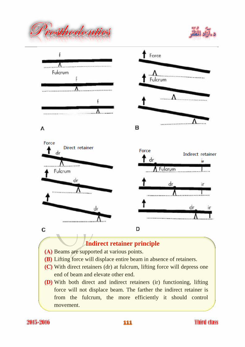
Indirect retainer principle
Beams are supported at various points.
Lifting force will displace entire beam in absence of retainers.
With direct retainers (dr) at fulcrum, lifting force will depress one
end of beam and elevate other end.
With both direct and indirect retainers (ir) functioning, lifting
force will not displace beam. The farther the indirect retainer is
from the fulcrum, the more efficiently it should control
movement.
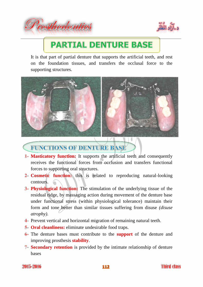
It is that part of partial denture that supports the artificial teeth, and rest
on the foundation tissues, and transfers the occlusal force to the
supporting structures.
It supports the artificial teeth and consequently Masticatory function:
receives the functional forces from occlusion and transfers functional
forces to supporting oral structures.
this is related to reproducing natural-looking Cosmetic function:
contours.
The stimulation of the underlying tissue of the Physiological function:
residual ridge, by massaging action during movement of the denture base
under functional stress (within physiological tolerance) maintain their
form and tone better than similar tissues suffering from disuse (disuse
atrophy).
Prevent vertical and horizontal migration of remaining natural teeth.
eliminate undesirable food traps. Oral cleanliness:
The denture bases must contribute to the of the denture and support
improving prosthesis . stability
is provided by the intimate relationship of denture Secondary retention
bases
In a tooth-supported prosthesis, the denture base is primarily a span
between two abutments supporting artificial teeth. Thus occlusal forces
are transferred directly to the abutments through rests. Also, the denture
base and the supplied teeth serve to prevent horizontal migration of all of
the abutment teeth in the partially edentulous arch and vertical migration
of teeth in the opposing arch. When anterior teeth are replaced, esthetics
may be of primary importance. Future relining or rebasing may not be
necessary to reestablish support. Relining is necessary only when tissue
changes have occurred beneath the tooth-supported base to the point that
poor esthetics or accumulation of debris result.
In a distal extension partial denture, the denture bases must contribute to
the support of the denture and improving prosthesis stability.
Maximum support from the residual ridge may be obtained by using
broad, accurate denture bases, which spread the occlusal load equitably
over the entire area available for such support (snowshoe principle).
Therefore support should be the primary consideration in selecting,
designing, and fabricating a distal extension partial denture base. It must
be made of a material that can be relined or rebased when it becomes
necessary to reestablish tissue support for the distal extension base.
Secondary retention is provided by the intimate relationship of denture
bases, Retention of denture bases has been described as the result of the
following forces:
Adhesion.
Cohesion.
Atmospheric pressure.
Physiological molding of the tissue around the polished surfaces of
the denture.
Effect of gravity on the mandibular denture.
Using mesial rest on the last abutments. 1-
Using indirect retainers. 2-
Using special type of direct retainers, the first choice is R.P.I system, 3-
second choice is I bar, and the third choice is combination clasp.
Relining the finished free end extension partial denture before insertion 4-
inside patient mouth.
Using special kind of impression technique called altered cast technique. 5-
Using implant to support the denture base. 6-
Using a stress breaker if indicated. 7-
It is most widely used type of denture base because of easy fabrication
and easy of attachment to metal framework.
The resin denture base is indicated for distal extension cases (class I and
class II) because of the support of the denture by tissue and ridge and
denture base, so there will be need for relining.
In class III and class IV edentulous cases because of possibility of tissue
changes underneath the denture base and there will be need for futural
relining.
Since after healing period there will be need for relining so that resin
denture base will be needed for such cases.
Acrylic resin bases are attached to the partial denture framework by
means of minor connector; the method of attachment is mainly
mechanical by undercuts or holes. Relief over the basal seat areas of the
master cast is used; after casting, the portion of the retentive framework
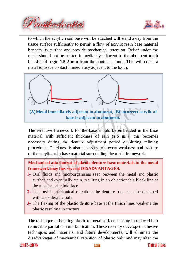
to which the acrylic resin base will be attached will stand away from the
tissue surface sufficiently to permit a flow of acrylic resin base material
beneath its surface and provide mechanical retention. Relief under the
mesh should not be started immediately adjacent to the abutment tooth
but should begin 1.5-2 mm from the abutment tooth. This will create a
metal to tissue contact immediately adjacent to the tooth.
(A) Metal immediately adjacent to abutment, (B) incorrect acrylic of
base is adjacent to abutment.
The retentive framework for the base should be embedded in the base
material with sufficient thickness of rein (1.5 mm) this becomes
necessary during the denture adjustment period or during relining
procedures. Thickness is also necessary to prevent weakness and fracture
of the acrylic resin base material surrounding the metal framework.
Mechanical attachment of plastic denture base materials to the metal
framework may has several DISADVANTAGES:
Oral fluids and microorganisms seep between the metal and plastic
surface and eventually stain, resulting in an objectionable black line at
the metal-plastic interface.
To provide mechanical retention; the denture base must be designed
with considerable bulk.
The flexing of the plastic denture base at the finish lines weakens the
plastic resulting in fracture.
The technique of bonding plastic to metal surface is being introduced into
removable partial denture fabrication. These recently developed adhesive
techniques and materials, and future developments, will eliminate the
disadvantages of mechanical retention of plastic only and may alter the
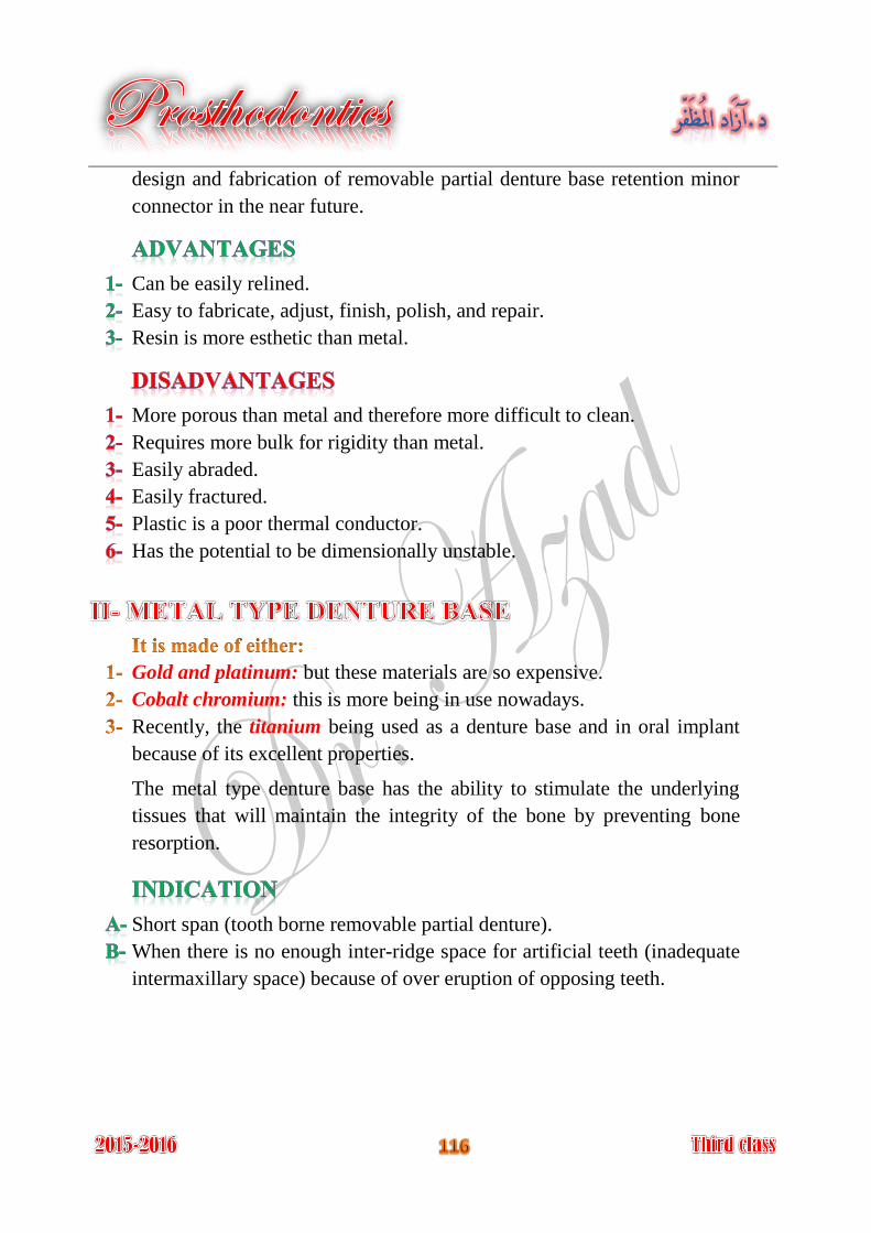
design and fabrication of removable partial denture base retention minor
connector in the near future.
Can be easily relined.
Easy to fabricate, adjust, finish, polish, and repair.
Resin is more esthetic than metal.
More porous than metal and therefore more difficult to clean.
Requires more bulk for rigidity than metal.
Easily abraded.
Easily fractured.
Plastic is a poor thermal conductor.
Has the potential to be dimensionally unstable.
Gold and platinum: but these materials are so expensive.
Cobalt chromium: this is more being in use nowadays.
Recently, the titanium being used as a denture base and in oral implant
because of its excellent properties.
The metal type denture base has the ability to stimulate the underlying
tissues that will maintain the integrity of the bone by preventing bone
resorption.
Short span (tooth borne removable partial denture).
When there is no enough inter-ridge space for artificial teeth (inadequate
intermaxillary space) because of over eruption of opposing teeth.
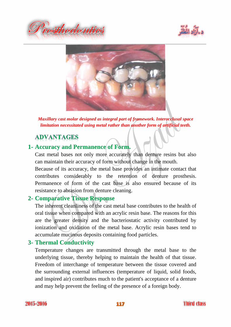
Maxillary cast molar designed as integral part of framework. Interocclusal space
limitation necessitated using metal rather than another form of artificial teeth.
1- Accuracy and Permanence of Form.
Cast metal bases not only more accurately than denture resins but also
can maintain their accuracy of form without change in the mouth.
Because of its accuracy, the metal base provides an intimate contact that
contributes considerably to the retention of denture prosthesis.
Permanence of form of the cast base is also ensured because of its
resistance to abrasion from denture cleaning.
2- Comparative Tissue Response
The inherent cleanliness of the cast metal base contributes to the health of
oral tissue when compared with an acrylic resin base. The reasons for this
are the greater density and the bacteriostatic activity contributed by
ionization and oxidation of the metal base. Acrylic resin bases tend to
accumulate mucinous deposits containing food particles.
3- Thermal Conductivity
Temperature changes are transmitted through the metal base to the
underlying tissue, thereby helping to maintain the health of that tissue.
Freedom of interchange of temperature between the tissue covered and
the surrounding external influences (temperature of liquid, solid foods,
and inspired air) contributes much to the patient's acceptance of a denture
and may help prevent the feeling of the presence of a foreign body.
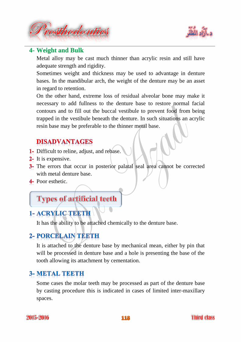
4- Weight and Bulk
Metal alloy may be cast much thinner than acrylic resin and still have
adequate strength and rigidity.
Sometimes weight and thickness may be used to advantage in denture
bases. In the mandibular arch, the weight of the denture may be an asset
in regard to retention.
On the other hand, extreme loss of residual alveolar bone may make it
necessary to add fullness to the denture base to restore normal facial
contours and to fill out the buccal vestibule to prevent food from being
trapped in the vestibule beneath the denture. In such situations an acrylic
resin base may be preferable to the thinner metal base.
Difficult to reline, adjust, and rebase.
It is expensive.
The errors that occur in posterior palatal seal area cannot be corrected
with metal denture base.
Poor esthetic.
It has the ability to be attached chemically to the denture base.
It is attached to the denture base by mechanical mean, either by pin that
will be processed in denture base and a hole is presenting the base of the
tooth allowing its attachment by cementation.
Some cases the molar teeth may be processed as part of the denture base
by casting procedure this is indicated in cases of limited inter-maxillary
spaces.
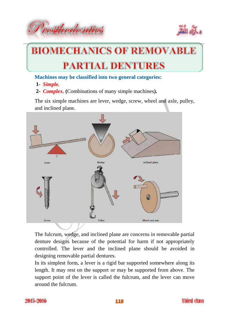
Machines may be classified into two general categories:
1- Simple.
2- Complex. (Combinations of many simple machines).
The six simple machines are lever, wedge, screw, wheel and axle, pulley,
and inclined plane.
The fulcrum, wedge, and inclined plane are concerns in removable partial
denture designs because of the potential for harm if not appropriately
controlled. The lever and the inclined plane should be avoided in
designing removable partial dentures.
In its simplest form, a lever is a rigid bar supported somewhere along its
length. It may rest on the support or may be supported from above. The
support point of the lever is called the fulcrum, and the lever can move
around the fulcrum.
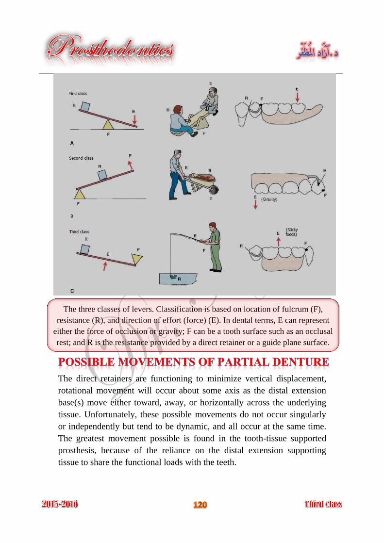
The three classes of levers. Classification is based on location of fulcrum (F),
resistance (R), and direction of effort (force) (E). In dental terms, E can represent
either the force of occlusion or gravity; F can be a tooth surface such as an occlusal
rest; and R is the resistance provided by a direct retainer or a guide plane surface.
The direct retainers are functioning to minimize vertical displacement,
rotational movement will occur about some axis as the distal extension
base(s) move either toward, away, or horizontally across the underlying
tissue. Unfortunately, these possible movements do not occur singularly
or independently but tend to be dynamic, and all occur at the same time.
The greatest movement possible is found in the tooth-tissue supported
prosthesis, because of the reliance on the distal extension supporting
tissue to share the functional loads with the teeth.
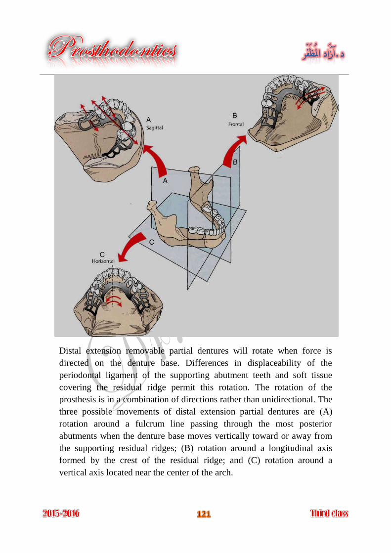
Distal extension removable partial dentures will rotate when force is
directed on the denture base. Differences in displaceability of the
periodontal ligament of the supporting abutment teeth and soft tissue
covering the residual ridge permit this rotation. The rotation of the
prosthesis is in a combination of directions rather than unidirectional. The
three possible movements of distal extension partial dentures are (A)
rotation around a fulcrum line passing through the most posterior
abutments when the denture base moves vertically toward or away from
the supporting residual ridges; (B) rotation around a longitudinal axis
formed by the crest of the residual ridge; and (C) rotation around a
vertical axis located near the center of the arch.
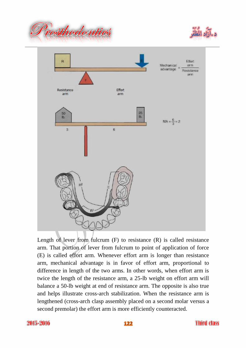
Length of lever from fulcrum (F) to resistance (R) is called resistance
arm. That portion of lever from fulcrum to point of application of force
(E) is called effort arm. Whenever effort arm is longer than resistance
arm, mechanical advantage is in favor of effort arm, proportional to
difference in length of the two arms. In other words, when effort arm is
twice the length of the resistance arm, a 25-lb weight on effort arm will
balance a 50-lb weight at end of resistance arm. The opposite is also true
and helps illustrate cross-arch stabilization. When the resistance arm is
lengthened (cross-arch clasp assembly placed on a second molar versus a
second premolar) the effort arm is more efficiently counteracted.
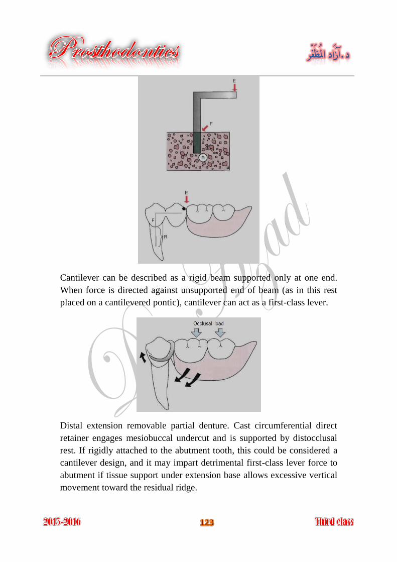
Cantilever can be described as a rigid beam supported only at one end.
When force is directed against unsupported end of beam (as in this rest
placed on a cantilevered pontic), cantilever can act as a first-class lever.
Distal extension removable partial denture. Cast circumferential direct
retainer engages mesiobuccal undercut and is supported by distocclusal
rest. If rigidly attached to the abutment tooth, this could be considered a
cantilever design, and it may impart detrimental first-class lever force to
abutment if tissue support under extension base allows excessive vertical
movement toward the residual ridge.
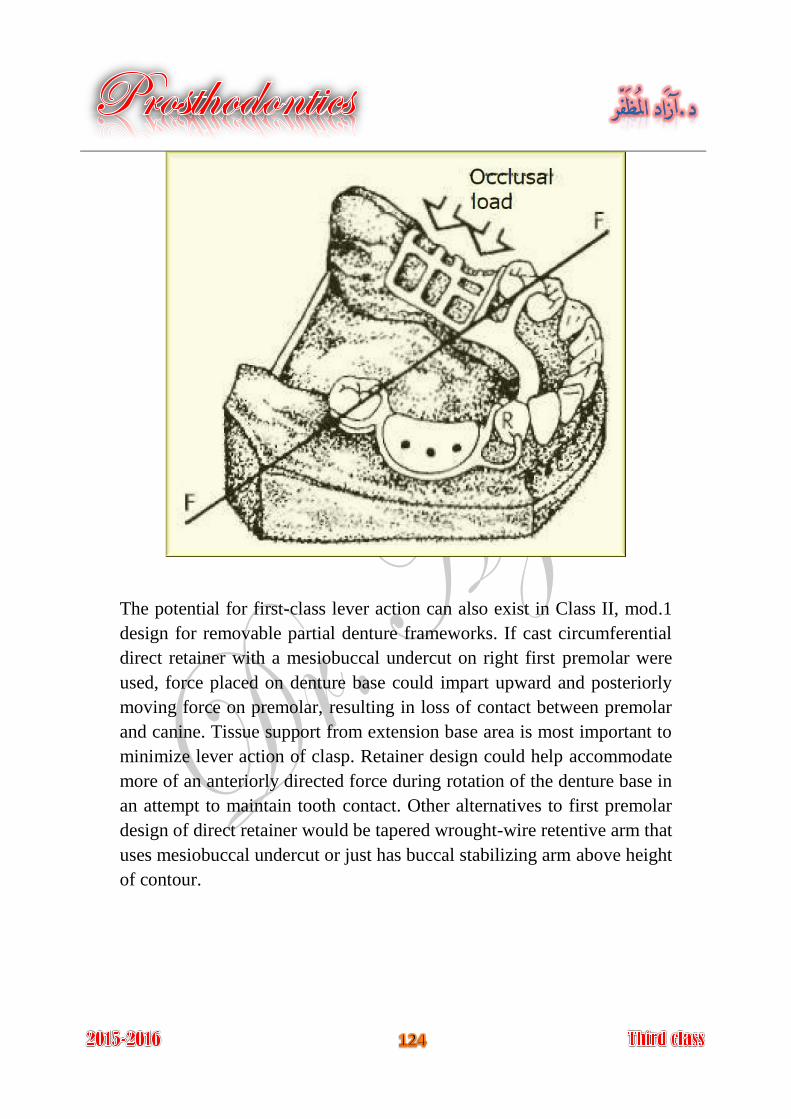
The potential for first-class lever action can also exist in Class II, mod.1
design for removable partial denture frameworks. If cast circumferential
direct retainer with a mesiobuccal undercut on right first premolar were
used, force placed on denture base could impart upward and posteriorly
moving force on premolar, resulting in loss of contact between premolar
and canine. Tissue support from extension base area is most important to
minimize lever action of clasp. Retainer design could help accommodate
more of an anteriorly directed force during rotation of the denture base in
an attempt to maintain tooth contact. Other alternatives to first premolar
design of direct retainer would be tapered wrought-wire retentive arm that
uses mesiobuccal undercut or just has buccal stabilizing arm above height
of contour.
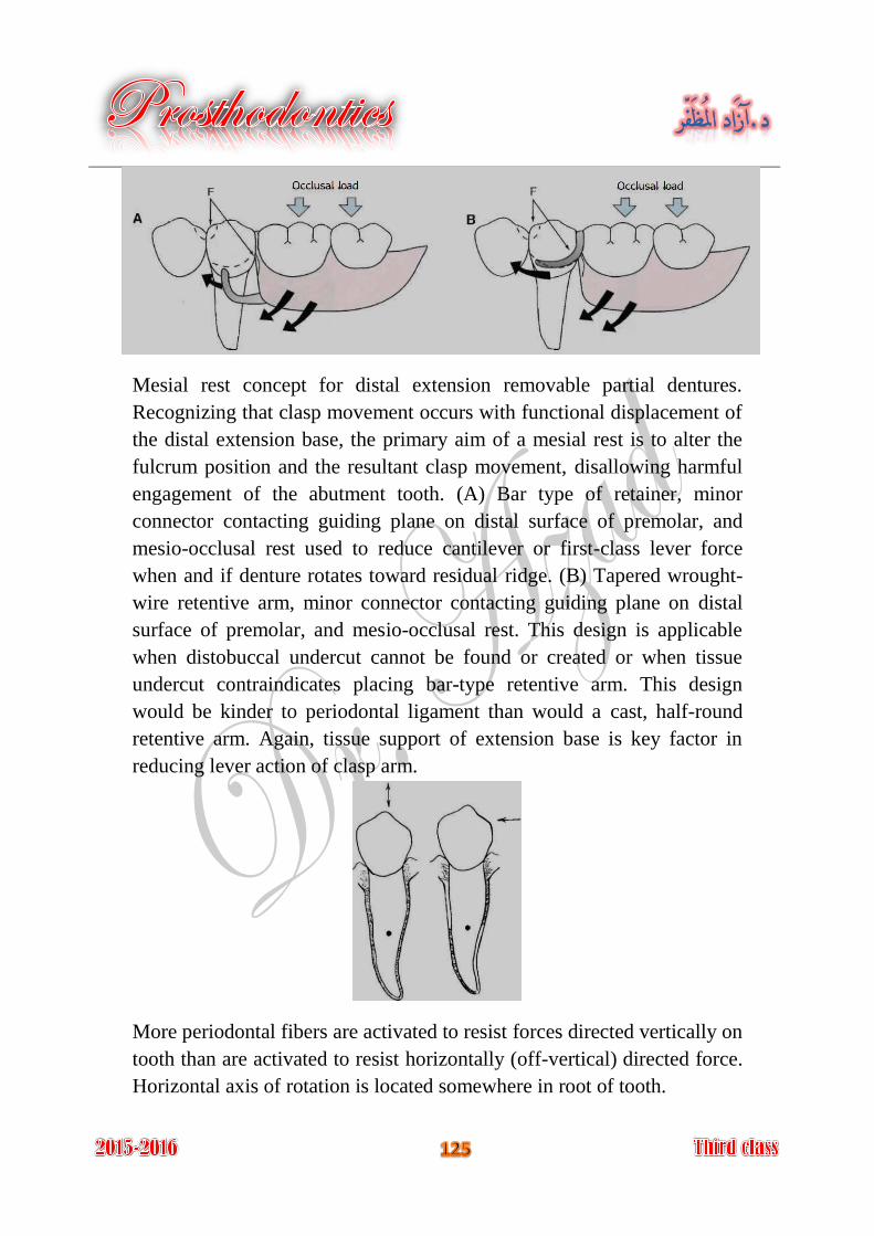
Mesial rest concept for distal extension removable partial dentures.
Recognizing that clasp movement occurs with functional displacement of
the distal extension base, the primary aim of a mesial rest is to alter the
fulcrum position and the resultant clasp movement, disallowing harmful
engagement of the abutment tooth. (A) Bar type of retainer, minor
connector contacting guiding plane on distal surface of premolar, and
mesio-occlusal rest used to reduce cantilever or first-class lever force
when and if denture rotates toward residual ridge. (B) Tapered wrought-
wire retentive arm, minor connector contacting guiding plane on distal
surface of premolar, and mesio-occlusal rest. This design is applicable
when distobuccal undercut cannot be found or created or when tissue
undercut contraindicates placing bar-type retentive arm. This design
would be kinder to periodontal ligament than would a cast, half-round
retentive arm. Again, tissue support of extension base is key factor in
reducing lever action of clasp arm.
More periodontal fibers are activated to resist forces directed vertically on
tooth than are activated to resist horizontally (off-vertical) directed force.
Horizontal axis of rotation is located somewhere in root of tooth.
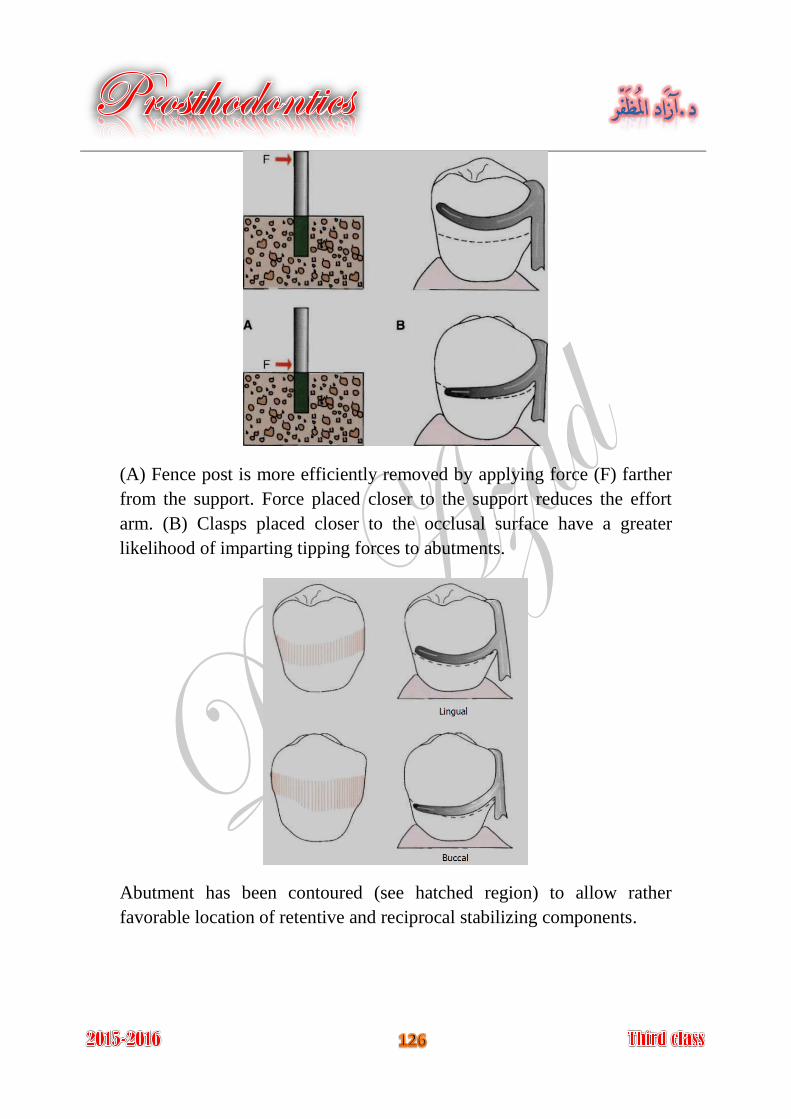
(A) Fence post is more efficiently removed by applying force (F) farther
from the support. Force placed closer to the support reduces the effort
arm. (B) Clasps placed closer to the occlusal surface have a greater
likelihood of imparting tipping forces to abutments.
Abutment has been contoured (see hatched region) to allow rather
favorable location of retentive and reciprocal stabilizing components.
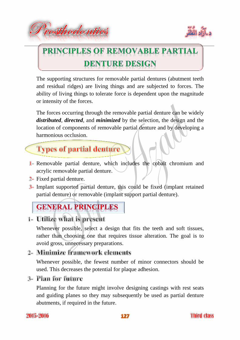
The supporting structures for removable partial dentures (abutment teeth
and residual ridges) are living things and are subjected to forces. The
ability of living things to tolerate force is dependent upon the magnitude
or intensity of the forces.
The forces occurring through the removable partial denture can be widely
distributed, directed, and minimized by the selection, the design and the
location of components of removable partial denture and by developing a
harmonious occlusion.
Removable partial denture, which includes the cobalt chromium and
acrylic removable partial denture.
Fixed partial denture.
Implant supported partial denture, this could be fixed (implant retained
partial denture) or removable (implant support partial denture).
Whenever possible, select a design that fits the teeth and soft tissues,
rather than choosing one that requires tissue alteration. The goal is to
avoid gross, unnecessary preparations.
Whenever possible, the fewest number of minor connectors should be
used. This decreases the potential for plaque adhesion.
Planning for the future might involve designing castings with rest seats
and guiding planes so they may subsequently be used as partial denture
abutments, if required in the future.
Cast clasps cover more tooth surface than wrought clasps. The latter
would be preferred if caries incidence is higher than usual.
It is better to redesigning the partial denture to avoid these restorations
(have high creep values and low yield strength) or to replace the
restorations with onlays or crowns.
Which arch , because each arch may have certain is needed to be restored
criteria indicates specific design, and if both arches are needed to be
restored, the relationship between maxillary and mandibular arches in
removable partial denture designing and construction may consider:
A- Inter-ridge space as well as space available for missing teeth
restoration.
B- Orientation of occlusal plane.
C- Occlusal relationship of remaining teeth.
D- Arch integrity.
E- Tooth morphology.
cases supported entirely by teeth are differ than cases Type of support:
with tooth-tissue support, if one or more distal extension bases are
involved, the following must be considered:
A- Type of secondary impression material and technique.
B- Clasp design that will best minimize the forces applied to the
abutment teeth during function.
C- Need for indirect retention.
D- Need for later relining or rebasing, which influence the type of base
material used.
selection and modifications required (simple grinding to Abutment teeth
more complicated restorations or splinting). This may affect the clasp
design and type.
Considerations in abutment teeth selection are:
A- Tooth number and location in the arch relative to edentulous spaces.
B- Periodontal health.
C- Crown and root morphology.
D- Crown to root ratio.
E- Bone support (tooth response to stress (index area)).
F- Opposing dentition relationship of the tooth to the other supporting
unites (length of the edentulous span).
Type of indicated. major connector
to be used for the framework and for the bases. Materials
Type of to be used, this may influenced by the opposing artificial teeth
teeth. In general, removable partial dentures opposing natural teeth will
require greater support and stabilization over time because of the greater
functional load demands. Therefore occlusal relationships at maximum
intercuspation should be broadly dissipated to the supporting units.
and his experience with removable partial Patient past dental history
denture and the reasons for making a new one, e.g. if patient was
objectionable for an anterior palatal bar because bulky, location or tissue
irritation, another major connector could be used and located more
posteriorly.
Using of to restore missing tooth as other types of treatment modalities
replacing of single missed anterior teeth by fixed restoration or benefits
from implant to simplify the removable partial denture design.
Response of to previous stress. oral structures
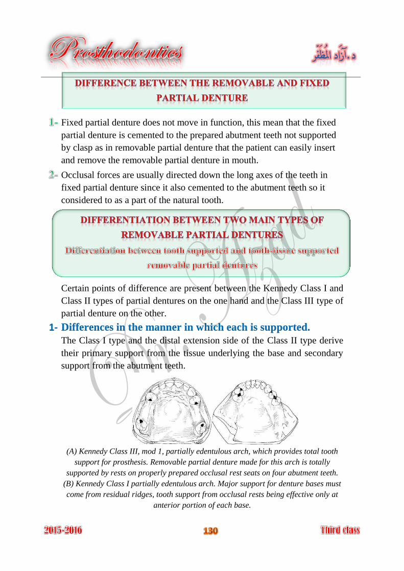
Fixed partial denture does not move in function, this mean that the fixed
partial denture is cemented to the prepared abutment teeth not supported
by clasp as in removable partial denture that the patient can easily insert
and remove the removable partial denture in mouth.
Occlusal forces are usually directed down the long axes of the teeth in
fixed partial denture since it also cemented to the abutment teeth so it
considered to as a part of the natural tooth.
Certain points of difference are present between the Kennedy Class I and
Class II types of partial dentures on the one hand and the Class III type of
partial denture on the other.
1- Differences in the manner in which each is supported.
The Class I type and the distal extension side of the Class II type derive
their primary support from the tissue underlying the base and secondary
support from the abutment teeth.
(A) Kennedy Class III, mod 1, partially edentulous arch, which provides total tooth
support for prosthesis. Removable partial denture made for this arch is totally
supported by rests on properly prepared occlusal rest seats on four abutment teeth.
(B) Kennedy Class I partially edentulous arch. Major support for denture bases must
come from residual ridges, tooth support from occlusal rests being effective only at
anterior portion of each base.
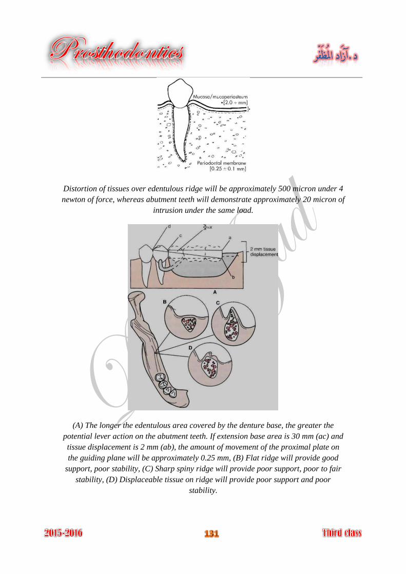
Distortion of tissues over edentulous ridge will be approximately 500 micron under 4
newton of force, whereas abutment teeth will demonstrate approximately 20 micron of
intrusion under the same load.
(A) The longer the edentulous area covered by the denture base, the greater the
potential lever action on the abutment teeth. If extension base area is 30 mm (ac) and
tissue displacement is 2 mm (ab), the amount of movement of the proximal plate on
the guiding plane will be approximately 0.25 mm, (B) Flat ridge will provide good
support, poor stability, (C) Sharp spiny ridge will provide poor support, poor to fair
stability, (D) Displaceable tissue on ridge will provide poor support and poor
stability.
2- Differences in the method of impression registration and jaw
. An impression registration for the fabrication of a record require
partial denture must fulfill the following two requirements:
and the relationship of the remaining teeth in the
dental arch and the surrounding soft tissue must be recorded accurately so
that the denture will not exert pressure on those structures beyond their
physiological limits. The elastic impression materials, such as irreversible
hydrocolloid (alginate), mercaptan rubber base (Thiokol), silicone
impression materials (both condensation and addition reaction), and the
polyethers are best suited for this purpose.
of the soft tissue underlying the distal extension
base of the partial denture should be recorded so that firm areas are used
as primary stress-bearing areas and readily displaceable tissues are not
overloaded. An impression material capable of displacing tissue
sufficiently to register the supporting form of the ridge will fulfill this
second requirement.
No single impression material can satisfactorily fulfill both of the
previously mentioned requirements.
3- exists in the distal Differences in the need for indirect retention
extension type of partial denture, whereas in the tooth-supported (Class
III) there is no extension base to lift away from the supporting tissue,
because a direct retainer on an abutment tooth secures each end of each
denture base.
4- that can be relined to Differences in the type of the base material
compensate for tissue changes. Acrylic resin is generally used as a base
material for distal extension bases. The Class III partial denture, on the
other hand, metal bases therefore are more frequently used in tooth
supported restorations, since relining is not as likely to be necessary with
them.
5- Differences in Clasp Design
The tooth-supported partial denture is retained and stabilized by a clasp at
each end of each edentulous space. Cast retentive arms are generally used
for this purpose. These may be either circumferential or bar clasp.
In the tooth-tissue supported removable partial dentures, because of the
anticipated functional movement of the distal extension base, the direct
retainer adjacent to the distal extension base must be able to flex
sufficiently to dissipate stresses that otherwise would be transmitted
directly to the abutment tooth as leverage, in addition to that of resisting
vertical displacement. A retentive clasp arm made of wrought wire can
flex more readily in all directions than can the cast half-round clasp arm.
Thereby, it may more effectively dissipate those stresses (combination
clasp), or R.P.I. system, or stress breaker may be used.
Design of the partial denture framework should be systematically
developed and outlined on an accurate diagnostic cast based on the
following prosthesis concepts:
Where the prosthesis is supported.
In an entirely tooth-supported partial denture, the most ideal location for
the support units (rests) in a prepared rest seats on abutment teeth. in a
tooth-tissue supported partial denture, attention to these same
considerations must be given to the abutment teeth. However, equitable
support must come from the edentulous ridge areas.
How the support is connected.
Connect the tooth and tissue support units. Designing and locating major
and minor connectors.
How the prosthesis is retained.
The retention must be sufficient to resist reasonable dislodging forces.
Retention is accomplished by mechanical retaining elements (clasps)
being placed on the abutment teeth.
How the retention and support are connected.
If direct and indirect retainers are to function as designed, each must be
rigidly attached to the major connector.
How the edentulous base support is connected.
It is necessary to ensure rigidity of the base material without interfering
with tooth placement.
Introduction to the patient and know the chief complain (clinical step).
Diagnosis and filling a case sheet with preparation and motivation the
patient to the treatment (clinical step).
Treatment planning and suggestion of the prognosis after deciding to
make removable partial denture (clinical step).
Making a study cast (for the offending arch and the opposing arch) by
primary impression (clinical step).
Surveying the study cast by using the dental surveyor (laboratory step).
Suggestion of the removable partial denture design on the surveyed study
cast, and determination of rests number and location (laboratory step).
Preparation of abutment teeth, reshaping, occlusal rest seat, restoration,
crowning (clinical step).
Special tray fabrication using the study model (laboratory step).
Making the final impression with special tray (clinical step).
Resurveying the master cast (laboratory step).
Block out and relief the master cast (laboratory step).
The block out master cast must be placed in a water bath contain piece of
plaster or stone (slurry) at a maximum temperature of 38°C for 5-10
minutes before duplication, so that the cast will not etched because the
water already contains calcium sulfate, and to allow the escape of any air
trapped beneath the relief wax on the master cast (laboratory step).
Duplication the master cast by tertiary impression by agar to produce a
refractory cast from investment material (laboratory step).
Dipping the refractory cast in Bee's wax and drying in oven, to make the
cast surface smooth and dense, and to facilitate the adhesion of wax and
plastic patterns to the refractory cast (laboratory step).
Form the wax pattern on the duplicated cast according to the establish
design, wax and plastic pattern (readymade) are used to form the pattern
of the removable partial denture framework; these patterns are available
in a variety of shape, size, and thickness (laboratory step).
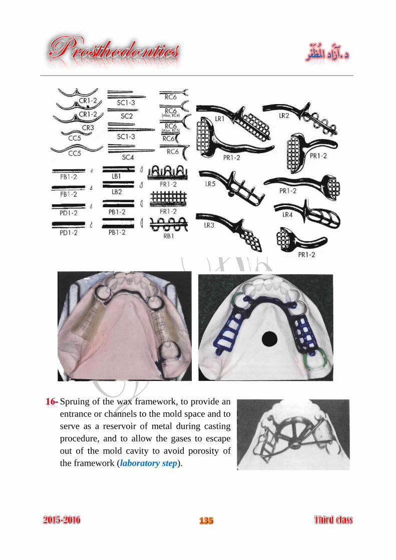
Spruing of the wax framework, to provide an
entrance or channels to the mold space and to
serve as a reservoir of metal during casting
procedure, and to allow the gases to escape
out of the mold cavity to avoid porosity of
the framework (laboratory step).
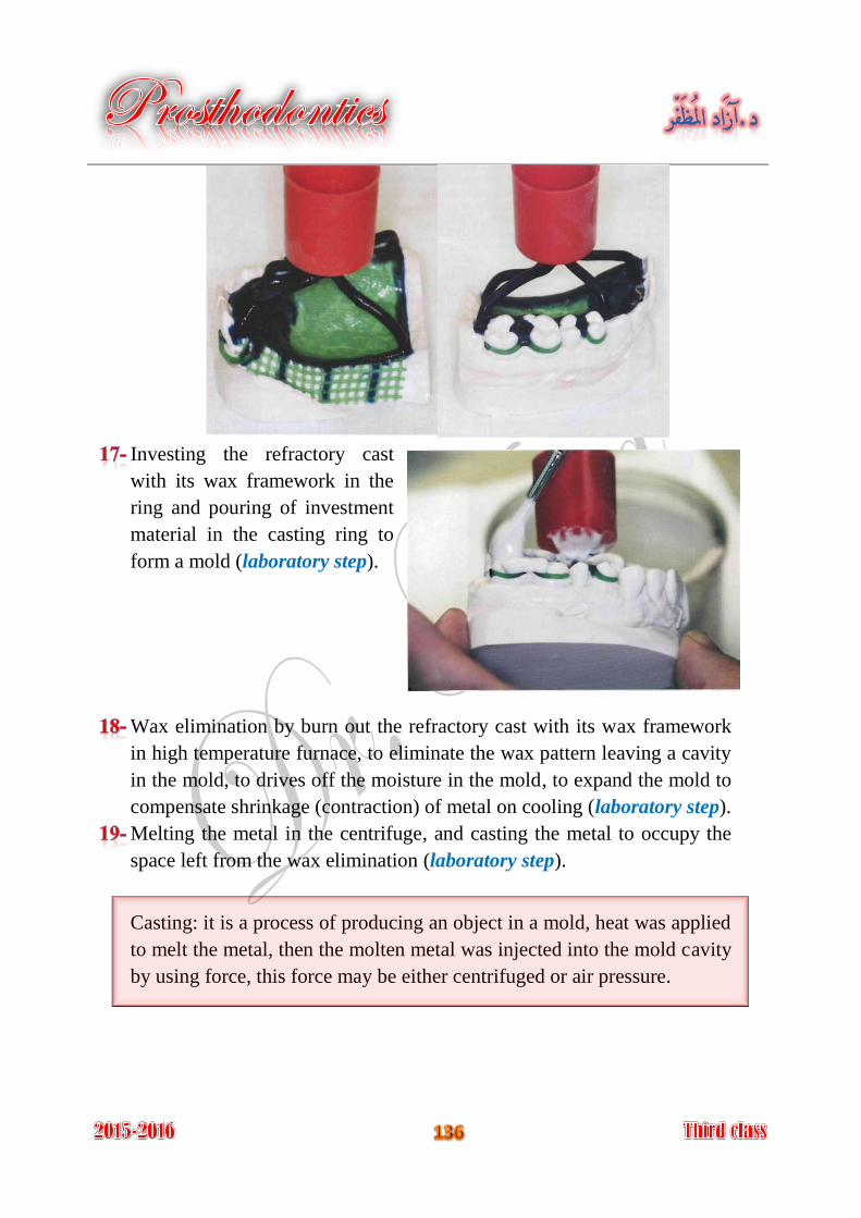
Investing the refractory cast
with its wax framework in the
ring and pouring of investment
material in the casting ring to
form a mold (laboratory step).
Wax elimination by burn out the refractory cast with its wax framework
in high temperature furnace, to eliminate the wax pattern leaving a cavity
in the mold, to drives off the moisture in the mold, to expand the mold to
compensate shrinkage (contraction) of metal on cooling (laboratory step).
Melting the metal in the centrifuge, and casting the metal to occupy the
space left from the wax elimination (laboratory step).
Casting: it is a process of producing an object in a mold, heat was applied
to melt the metal, then the molten metal was injected into the mold cavity
by using force, this force may be either centrifuged or air pressure.
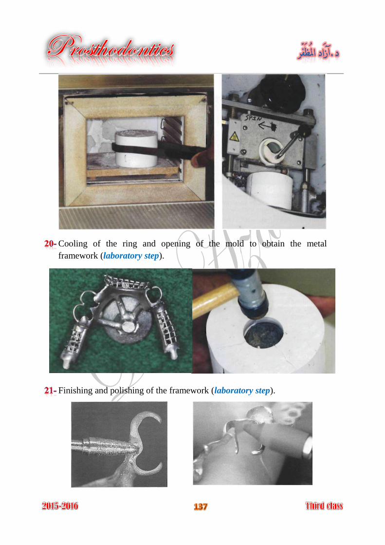
Cooling of the ring and opening of the mold to obtain the metal
framework (laboratory step).
Finishing and polishing of the framework (laboratory step).
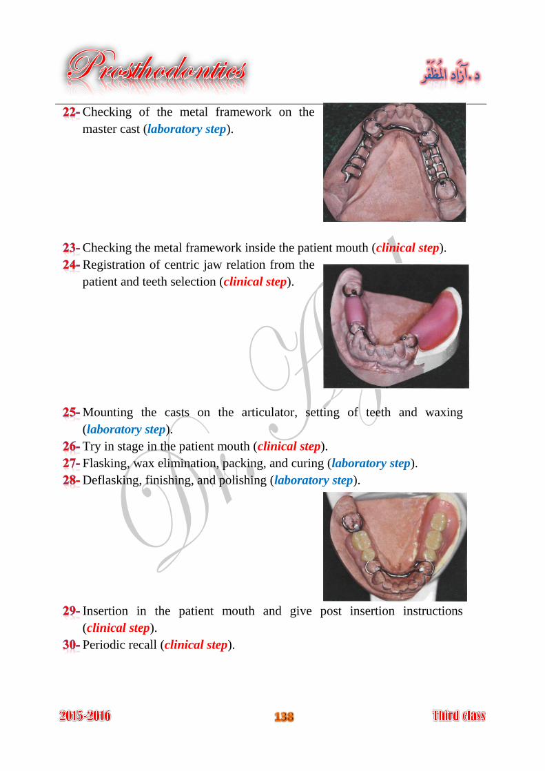
Checking of the metal framework on the
master cast (laboratory step).
Checking the metal framework inside the patient mouth (clinical step).
Registration of centric jaw relation from the
patient and teeth selection (clinical step).
Mounting the casts on the articulator, setting of teeth and waxing
(laboratory step).
Try in stage in the patient mouth (clinical step).
Flasking, wax elimination, packing, and curing (laboratory step).
Deflasking, finishing, and polishing (laboratory step).
Insertion in the patient mouth and give post insertion instructions
(clinical step).
Periodic recall (clinical step).
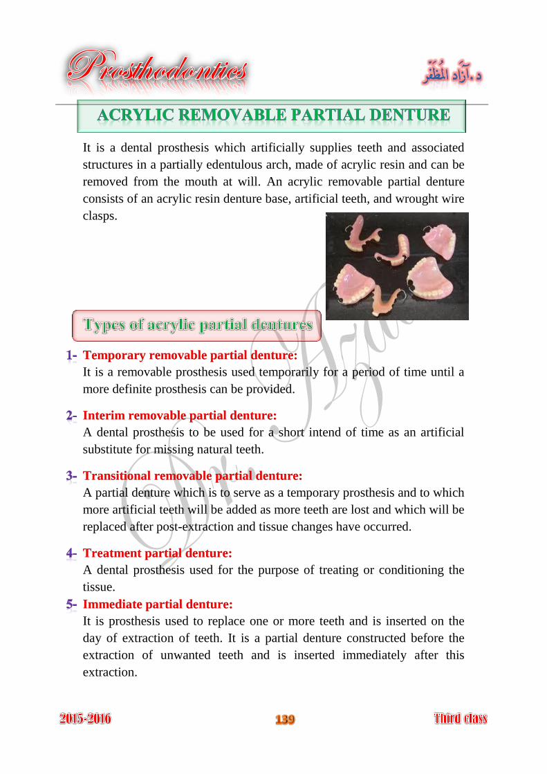
It is a dental prosthesis which artificially supplies teeth and associated
structures in a partially edentulous arch, made of acrylic resin and can be
removed from the mouth at will. An acrylic removable partial denture
consists of an acrylic resin denture base, artificial teeth, and wrought wire
clasps.
Temporary removable partial denture:
It is a removable prosthesis used temporarily for a period of time until a
more definite prosthesis can be provided.
Interim removable partial denture:
A dental prosthesis to be used for a short intend of time as an artificial
substitute for missing natural teeth.
Transitional removable partial denture:
A partial denture which is to serve as a temporary prosthesis and to which
more artificial teeth will be added as more teeth are lost and which will be
replaced after post-extraction and tissue changes have occurred.
Treatment partial denture:
A dental prosthesis used for the purpose of treating or conditioning the
tissue.
Immediate partial denture:
It is prosthesis used to replace one or more teeth and is inserted on the
day of extraction of teeth. It is a partial denture constructed before the
extraction of unwanted teeth and is inserted immediately after this
extraction.
In young patients when the pulp chamber is so large that a fixed
prosthesis is not feasible.
As space maintainer: recent extraction or premature loss of teeth resulting
in a space, to maintain this space we have to make an acrylic temporary
treatment.
In young patient: it is important to maintain the space until adjacent A-
teeth have fully erupted to be used as abutments for fixed restorations.
In adult: the maintenance of space can prevent migration of adjacent B-
teeth, extrusion, or over-eruption of opposing teeth.
Elderly patients, whose general health contraindicate lengthy procedure.
Cost: acrylic removable partial denture is considerably less than that for
metallic partial denture or fixed partial denture.
Serviceable for periodontically weakened standing teeth.
Interim (temporary) prosthesis: may be used:
When denture is needed while healing is progressing after extraction A-
or surgery.
Denture is needed while prolonged treatment is being accomplished. B-
The patient has no enough time at the moment for lengthy definite C-
treatment.
Transitional partial denture: during the periodic shift from a partial
denture to complete denture.
Treatment partial denture: may be used:
As vehicle to carry tissue treatment material for abused oral tissue A-
(tissue conditioner).
To reestablish the vertical dimension of occlusion on temporary B-
bases, while the results of the increase can be observed.
As a splint for surgical correction in the oral cavity. C-
As a night-guard or mouth protective device to correct or control D-
undesirable oral habits or to protect the mouth and teeth from trauma.
As immediate partial denture.
Not expensive.
Light weight.
Simpler design.
Easily constructed.
Easily added artificial teeth, if natural teeth are extracted.
Easily relined if bone resorbed.
Easily repaired if fractured.
Good appearance if extended labially or buccally because it is color
resembles that of gingiva.
Easily adjusted by grinding at chair-side.
Less patient response and tolerance for acrylic dentures than metallic
dentures.
Poor thermal conductivity.
Lower strength, therefore:
Easily broken. A-
Must be constructed in thick section. B-
The denture is somewhat larger and bulker. C-
Not rigid enough for ideal connection.
Tendency for warpage if overheated during polishing or during recurring
in repair or reline.
Design difficulties:
Ideal tooth support is difficult. A-
Ideal indirect retainer is difficult. B-
Unnecessary tissue coverage because of strength considerations. C-
Impossible to use more sophisticated components (precision D-
attachments, stress breaker).
1- The acrylic denture base:
The base acts as a saddle and as connectors and has a reciprocal function
for the retentive wrought wire clasp arm.
2- Wrought wire clasps:
Wrought stainless steel wire clasps are used with acrylic partial dentures;
they are attached to the acrylic denture base by embedding their non-
retentive portion into the denture base.
The wrought wire clasps consist of a retentive portion and non-retentive
portion, which should be looped or twisted to help anchorage it in the
acrylic resin of the base.
The most commonly clasp design used for acrylic partial denture:
A- Simple circular clasp:
It is used for the teeth adjacent to the edentulous ridges. It starts lingually
and passes over the relieved ridge along the proximal surface of the
clasped tooth to engage buccal undercuts. It should pass 3-4 mm away
from the proximal surface of the clasped tooth, to allow grinding.
B- Half Jackson clasp:
It finds its application on molars and premolars when no edentulous space
exists on either side of the tooth. It starts lingually and passes up to cross
the occlusal plane on the embrasure between two neighboring teeth, then
down to the buccal surface to engage the undercut.
Generally wrought wires are either:
Embedding a portion of the wire in an acrylic resin denture base. A-
Soldering to a fabricated framework. B-
Casting the framework to the wire. C-
3- Acrylic teeth:
They are attached by chemical bond to acrylic denture base.