PROSSER® - Crane Pumps & Systems
22
A Crane Co. Company PROSSER ® INSTALLATION and OPERATION MANUAL HYMERGIBLE® Hydraulically Driven Submersible Dewatering Pumps IMPORTANT! Read all instructions in this manual before operating pump. As a result of Crane Pumps & Systems, Inc., constant product improvement program, product changes may occur. As such Crane Pumps & Systems reserves the right to change product without prior written notification. 420 Third Street 83 West Drive, Bramton Piqua, Ohio 45356 Ontario, Canada L6T 2J6 Phone: (937) 778-8947 Phone: (905) 457-6223 Fax: (937) 773-7157 Fax: (905) 457-2650 www.cranepumps.com Form No. 096965-Rev. G Series: 7-06000 7-08000 DISCONTINUED Parts may NOT be available
Transcript of PROSSER® - Crane Pumps & Systems

A Crane Co. Company
PROSSER®
INSTALLATION and OPERATION MANUALHYMERGIBLE® Hydraulically Driven
Submersible Dewatering Pumps
IMPORTANT! Read all instructions in this manual before operating pump.
As a result of Crane Pumps & Systems, Inc., constant product improvement program,
product changes may occur. As such Crane Pumps & Systems reserves the right to
change product without prior written notifi cation.
420 Third Street 83 West Drive, Bramton
Piqua, Ohio 45356 Ontario, Canada L6T 2J6
Phone: (937) 778-8947 Phone: (905) 457-6223
Fax: (937) 773-7157 Fax: (905) 457-2650
www.cranepumps.com Form No. 096965-Rev. G
Series: 7-06000
7-08000
DISCONTINUED
Parts may
NOT be available

2
TABLE OF CONTENTS
SAFETY FIRST ............................................................................................... 3
A. PUMP SPECIFICATIONS ................................................................................4 - 5
B. GENERAL INFORMATION ..............................................................................6
C. INSTALLATION ................................................................................................6
D. START-UP OPERATION ..................................................................................6 - 7
E. PREVENTATIVE MAINTENANCE ...................................................................7
F. SERVICE and REPAIR ....................................................................................8 - 11
G. REPLACEMENT PARTS ..................................................................................11
TROUBLE SHOOTING ....................................................................................12
SERIES: 7-06000 & 7-08000 CROSS-SECTION (Fig. 7) ...............................13
SERIES: 7-06000 & 7-08000 EXPLODED VIEW, (Fig. 8) ..............................14
PARTS LIST ...................................................................................................15 - 16
SERIES: 7-08000 2 Stage CROSS-SECTION (Fig. 9) ...................................17
SERIES: 7-08000 2 Stage EXPLODED VIEW, (Fig. 10) ................................18
PARTS LIST ...................................................................................................19
RETURNED GOODS POLICY .........................................................................20
WARRANTY ...................................................................................................21
START-UP REPORT ........................................................................................22
WARRANTY REGISTRATION
SPECIAL TOOLS AND EQUIPMENT
DIELECTRIC TESTER
PRESSURE GAUGE KIT (see parts list)
Other brand and product names are trademarks or registered trademarks of their respective holders.
HYMERGIBLE® is a registered trademark of Crane Pumps & Systems, Inc.
® PROSSER is a registered trademark of Crane Pumps & Systems, Inc
1996, 1997, 1998, 2002, 2/06, 9/06 Alteration Rights Reserved

3
Please Read This Before Installing Or Operating Pump.
This information is provided for SAFETY and to PREVENT
EQUIPMENT PROBLEMS. To help recognize this information,
observe the following symbols:
IMPORTANT! Warns about hazards that can result
in personal injury or Indicates factors concerned with
assembly, installation, operation, or maintenance which
could result in damage to the machine or equipment if
ignored.
CAUTION ! Warns about hazards that can or will cause minor
personal injury or property damage if ignored. Used with symbols
below.
WARNING ! Warns about hazards that can or will cause serious
personal injury, death, or major property damage if ignored. Used
with symbols below.
Only qualifi ed personnel should install, operate and repair pump.
WARNING! Operation against a closed
discharge valve will cause premature bearing
and seal failure on any pump, and on end
suction and self priming pump the heat build
may cause the generation of steam with resulting dangerous
pressures. It is recommended that a high case temperature
switch or pressure relief valve be installed on the pump body.
CAUTION! Pumps build up heat and pressure
during operation-allow time for pumps to cool
before handling or servicing.
WARNING! - DO NOT pump hazardous materials
(fl ammable, caustic, etc.) unless the pump is specifi cally
designed and designated to handle them.
Do not block or restrict discharge hose, as discharge
hose may whip under pressure.
WARNING! - DO NOT wear loose clothing that may
become entangled in the impeller or other moving parts.
WARNING! - Keep clear of suction and discharge
openings. DO NOT insert fi ngers in pump with power
connected.
Always wear eye protection when working on pumps.
Make sure lifting handles are securely fastened each
time before lifting. DO NOT operate pump without
safety devices in place. Always replace safety devices
that have been removed during service or repair.
Secure the pump in its operating position so it can not
tip over, fall or slide.
DO NOT exceed manufacturers recommendation for
maximum performance, as this could cause the motor
to overheat.
WARNING! Submersible Pumps are not approved for
use in swimming pools, recreational water installations,
decorative fountains or any installation where human
contact with the pumped fl uid is common.
WARNING! Products Returned Must Be Cleaned,
Sanitized, Or Decontaminated As Necessary Prior
To Shipment, To Insure That Employees Will Not Be
Exposed To Health Hazards In Handling Said Material.
All Applicable Laws And Regulations Shall Apply.
Bronze/brass and bronze/brass fi tted pumps may
contain lead levels higher than considered safe for
potable water systems. Lead is known to cause cancer
and birth defects or other reproductive harm. Various
government agencies have determined that leaded
copper alloys should not be used in potable water
applications. For non-leaded copper alloy materials of
construction, please contact factory.
IMPORTANT! - Crane Pumps & Systems, Inc. is not
responsible for losses, injury, or death resulting from a
failure to observe these safety precautions, misuse or
abuse of pumps or equipment.
SAFETY FIRST!
Hazardous fl uids can
cause fi re or explo-
sions, burnes or death
could result.
Extremely hot - Severe
burnes can occur on contact.
Biohazard can cause
serious personal injury.
Hazardous fl uids can Hazard-
ous pressure, eruptions or ex-
plosions could cause personal
injury or property damage.
Rotating machinery
Amputation or severe
laceration can result.Eye protection required

4
LIQUID TEMP .................... 140ºF (60ºC)
DISCHARGE CASE ........... 356T6 Aluminum, Hard Anodized
DIFFUSER .......................... 356T6 Aluminum, Hard Anodized
SUCTION CASE ................ 356T6 Aluminum, Hard Anodized
with wear resistant polyurethane
liner
FRAME & OUTER CASE ... 6063T6 Aluminum, Hard Anodized
PUMP SHAFT .................... Stainless Steel
IMPELLER ......................... Stainless Steel
HARDWARE ...................... Stainless Steel
O-RINGS ............................ Buna
SEAL: Design .......... Mechanical, Oil Lubricated
Material ......... Rotating Faces - Carbon
Stationary Faces - Ceramic
Elastomer - Buna-N
Hardware -300 Series Stainless
STRAINER ......................... 300 Series Stainless Steel
.25" (6.35mm) Holes
UPPER BEARING:
Design .......... Single Row, Ball
Lubrication .... Prelubricated high-temperature
grease
Load ............. Radial
LOWER BEARING:
Design .......... Single Row, Ball
Lubrication .... Prelubricated high-temperature
grease
Load .............. Radial & Thrust
MOTOR: Design .......... Hydraulic, System should include
25 micron fi ltering
PUMP
SERIES
WEIGHT SHIPPING WT. / STD UNIT
PUMP DOMESTIC CUBES
7-06000 17lbs./7.7kg 23lbs./10.4kg 1.7Ft. /.05m
SECTION: A - PUMP SPECIFICATIONS: SERIES 7-06000
inches
(mm)
IMPORTANT !1.) PUMP MAY BE OPERATED “DRY” FOR EXTENDED PERIODS WITHOUT DAMAGE TO MOTOR AND/OR SEALS.
2.) THIS PUMP IS APPROPRIATE FOR THOSE APPLICATIONS SPECIFIED AS CLASS I DIVISION II HAZARDOUS LOCATIONS.
3.) THIS PUMP IS NOT APPROPRIATE FOR THOSE APPLICATIONS SPECIFIED AS CLASS I DIVISION I HAZARDOUS LOCATIONS.
4.) INSTALLATIONS SUCH AS DECORATIVE FOUNTAINS OR WATER FEATURES PROVIDED FOR VISUAL ENJOYMENT MUST BE INSTALLED IN
ACCORDANCE WITH THE NATIONAL ELECTRIC CODE ANSI/NFPA 70 AND/OR THE AUTHORITY HAVING JURISDICTION. THIS PUMP IS NOT
INTENDED FOR USE IN SWIMMING POOLS, RECREATIONAL WATER PARKS, OR INSTALLATIONS IN WHICH HUMAN CONTACT WITH PUMPED
MEDIA IS A COMMON OCCURRENCE.
EXTERNAL CONNECTION INTERNAL CONNECTION

5
inches
(mm)
SECTION: A - PUMP SPECIFICATIONS: SERIES 7-08000
LIQUID TEMP .................... 140ºF (60ºC)DISCHARGE CASE ........... 356T6 Aluminum, Hard AnodizedDIFFUSER .......................... 356T6 Aluminum, Hard AnodizedSUCTION CASE ................ 356T6 Aluminum, Hard Anodized w/wear resistant polyurethane linerFRAME & OUTER CASE ... 6063T6 Aluminum, Hard AnodizedWEAR PLATE .................... PolyurethanePUMP SHAFT .................... Stainless SteelIMPELLER ......................... Stainless SteelHARDWARE ...................... Stainless SteelO-RINGS ............................ BunaSEAL: Design .......... Mechanical, Oil Lubricated Material ......... Rotating Faces - Silicon Carbide Stationary Faces - Silicon Carbide Elastomer - Viton® Hardware -300 Series StainlessSTRAINER ......................... Series Stainless Steel .25" (6.35mm) HolesUPPER BEARING: Design .......... Single Row, Ball Lubrication .... Prelubricated high-temperature grease Load ............. Radial
LOWER BEARING: Single Stage Design .......... Single Row, Ball Lubrication .... Prelubricated high-temperature grease Load .............. Radial & Thrust LOWER BEARING: Two Stage Design .......... Double Row, Ball, Angular Contact Tandem Mounting Lubrication .... Prelubricated high-temperature grease Load .............. Radial & ThrustMOTOR: Design .......... Hydraulic, System should include 25 micron fi ltering
PUMP
SERIES
WEIGHT SHIPPING WT. / STD
UNIT
PUMP DOMESTIC CUBES
7-08306 & 7-08406 37lbs./16.9kg 42lbs./19.1kg 3.6Ft./.10m
7-08312 & 7-08412 41lbs./18.6kg 46lbs./20.9kg 3.6Ft./.10m
7-08312 & 7-08412
2 Stage
51lbs./24kg 56lbs./25.5kg 3.6Ft./.10m
EXTERNAL CONNECTION INTERNAL CONNECTION
A
B
G
E
F
AB
G
E
F
MODEL A B C - EXT D - EXT E - INT F - INT G
7-08306-020 19.37 (492) 17.13 (435) 2.00 (51) .37 (10) ----- ----- 7.50 (191)
7-08406-020 19.37 (492) 17.13 (435) ----- ----- 3.00 (76) .37 (10) 7.50 (191)
7-08312-020 19.62 (498) 17.38 (442) 3.00 (76) .50 (13) ----- ----- 7.50 (191)
7-08412-020 19.62 (498) 17.38 (442) ----- ----- 4.00 (102) .50 (13) 7.50 (191)
7-08312-215 21.28 (541) 19.03 (483) 3.00 (76) .50 (13) ----- ----- 7.38 (188)
7-08412-215 21.28 (541) 19.03 (483) ----- ----- 4.00 (102) .50 (13) 7.38 (188)
6
SECTION B: GENERAL INFORMATION
B-1) To the Purchaser:Congratulations! You are the owner of one of the fi nest pumps on the market today. These pumps are products engineered and manufactured of high quality components. Over one hundred years of pump building experience along with a continuing quality assurance program combine to produce a pump which will stand up to the toughest applications.
This manual will provide helpful information concerning installation, maintenance, and proper service guidelines.
B-2) Receiving:Upon receiving the pump, it should be inspected for damage or shortages. If damage has occurred, fi le a claim immediately with the company that delivered the pump. If the manual is removed from the packaging, do not lose or misplace.
B-3) Storage:Short Term - Prosser Pumps are manufactured for effi cient performance following short inoperative periods in storage. For best results, pumps can be retained in storage, as factory assembled, in a dry atmosphere with constant temperatures for up to six (6) months.
Long Term - Any length of time exceeding six (6) months, but not more than twenty four (24) months. The units should be stored in a temperature controlled area, a roofed over walled enclosure that provides protection from the elements (rain, snow, wind-blown dust, etc.), and whose temperature can be maintained between +40 deg. F and +120 deg. F.If extended high humidity is expected to be a problem, all exposed parts should be inspected before storage and all surfaces should then be sprayed with a rust-inhibiting oil.
Pump should be stored in its original shipping container. On initial start up, rotate impeller by hand to assure seal and impeller rotate freely. If it is required that the pump be installed and tested before the long term storage begins, such installation will be allowed provided:
1.) The pump is not installed under water for more than one (1) month.2.) Immediately upon satisfactory completion of the test, the pump is removed, thoroughly dried, repacked in the original shipping container, and placed in a temperature controlled storage area.
B-4) Service Centers:For the location of the nearest Prosser Service Center, check your Prosser representative or Crane Pumps & Systems, Inc., Service Department in Piqua, Ohio, telephone (937) 778-8947 or Crane Pumps & Systems Canada, Bramton, Ontario, (905) 457-6223.
SECTION C: INSTALLATIONC-1) Location:These pumping units are designed for use with hydraulic systems in locations where electrical connections are unavailable or hazardous. Before pumping fl uids other than water, consult the factory, giving fl uid, fl uid temperature, specifi c gravity, viscosity, capacity in USGPM and total head and/or pressure requirements, including friction loss through discharge line, fi ttings, valves, etc. Maximum fl uid temperature for sustained operation is 140°F (60°C) at specifi c gravity 1.0. Pump may operate up to 10 minutes running dry (not pumping water) without damage. DO NOT allow pump to be buried in mud or sand.
IMPORTANT ! - Pump Should Have Strainer Affi xed At All Times. Inspect And Clean The Pump Strainer Periodically For Maximum Effi ciency And Performance.
C-2) Discharge:Discharge hose is recommended. If rigid pipe is used, install so that there is no weight or strain on the pump. Install a short pipe nipple into the pump discharge to attach the discharge hose above the hydraulic connections at the top of the pump. Save and replace the plastic shipping plugs in the hydraulic line connection at the top of the pump whenever the hydraulic lines are disconnected. This is to protect against damage to the connections and entrance of dirt.
C-3) Suction:Completely submerge the suction strainer for maximum pumping effi ciency. Avoid entrance of air into the suction of the pump. Strainer should always be installed on the pump while operating.
C-4) Liquid Level Controls: (If Applicable)Attach “ON” fl oat to discharge hose or pump cable at desired pump “ON” level. Attach “OFF” fl oat to discharge hose or pump cable at desired pump “OFF” level. The “OFF” fl oat must be below the “ON” fl oat.
To attach the fl oats, thread the cable strap through the buckle with the ratchet pawl, cinch up tight, thread excess strapping through outer buckle slot. Be certain that the level controls cannot hang up or foul in its swing. It is recommended that the pump is completely submerged when the level control is in the “Off” mode.
C-5) Hydraulic System:Figure 1 shows a schematic drawing of a typical hydraulic power system for driving a submersible pump.
WARNING ! - Hydraulic system has high-pressure capability. Exercise caution at all times.
CAUTION ! - Never block return (low pressure) line. It’s best to use by-pass valve to control fl ow of hydraulic fl uid.
Maintain hydraulic fl uid temperature at 100°F (38°C) for
optimum performance. Maximum operating temperature is
180°F (82°C). See chart for viscosity of fl uid. Lower viscosity
fl uids can be used, but will increase the wear rate within the
hydraulic motor. A fi lter is required on the low pressure return
hydraulic fl uid line. Use fi lter elements rated at 25 micron
absolute. Protect hydraulic hoses from cuts and abrasion.
ALWAYS USE A BACK-UP WRENCH WHEN CONNECTING
AND DISCONNECTING THE HYDRAULIC LINES TO THE
FITTINGS ON TOP OF THE PUMP.
SECTION D: START-UP OPERATION
D-1) Check Pump Rotation:
Before putting pump into service for the fi rst time, the motor
rotation must be checked. To check the rotation, suspend the
pump freely, momentarily apply power, rotation of the pump
is clockwise when viewed from the suction end. To reverse
rotation, switch the two hydraulic lines. Reverse rotation will
not damage the pump, however, it will result in poor pump
performance.

7
D-2) Start-Up:
DO NOT attempt to start a frozen pump. Instead, submerge
pump in water for twenty (20) minutes before starting. DO NOT
attempt to thaw a frozen pump with a torch.
D-2.1) Report:
Included at the end of this manual are two start-up report
sheets, these sheets are to be completed as applicable.
Return one copy to the Crane Pumps & Systems, Inc. Service
Department and store the second with the pump manual. It is
important to record this data at initial start-up since it will be
useful to refer to should servicing the pump be required in the
future.
D-2.2) Identifi cation Plate:
Record the numbers from the pump’s identifi cation plate on
both START-UP REPORTS provided at the end of the manual
for future reference.
SECTION E: PREVENTIVE MAINTENANCE:
The following procedure must be followed to assure proper
pump operation.
1.) Servicing: Pump shall be restored to the state of original
safety, following disassembly.
2.) Renewals and Repairs: Special care shall be taken
in making renewals or repairs. Leave no parts off. Use
replacement parts furnished by the manufacturer.
3.) Fastenings: All bolts, nuts, screws and other means of
fastenings and also threaded covers, shall be in place, properly
tightened and secured.
4.) Shaft Seals: The seals should be inspected every 100
operating hours for wear (more often if abrasives are present).
To make a quick check of the seal’s condition, drain and
inspect the oil in the seal chamber (See Section F-1). If oil
removed from the pump contains water or abrasives, replace
seals. Change oil every 400 - 500 operating hours.
This pump is equipped with prelubricated bearings.
When a job is completed and before pumps are stored, drain
the oil from the seal chamber (a must before freezing weather).
If dirt or water are found in the oil, replace seals, bearings,
lower “O” rings and oil.
FIGURE 1
PUMP PART No. HYDRAULIC FLUID DATA
PSI (Max) FLOW -GPM VISCOSITY TEMPERATURE
7-06106-020 2000 7 (26.5 Liters) 214-320 SSU 100ºF (38ºC) - 180ºF (82ºC)
7-06206-020 2000 7 (26.5 Liters) 214-320 SSU 100ºF (38ºC) - 180ºF (82ºC)
7-08306-020 2000 7 (26.5 Liters) 214-320 SSU 100ºF (38ºC) - 180ºF (82ºC)
7-08406-020 2000 7 (26.5 Liters) 214-320 SSU 100ºF (38ºC) - 180ºF (82ºC)
7-08312-020 2000 12 (45.4 Liters) 214-320 SSU 100ºF (38ºC) - 180ºF (82ºC)
7-08412-020 2000 12 (45.4 Liters) 214-320 SSU 100ºF (38ºC) - 180ºF (82ºC)
7-08312-215 2000 12 (45.4 Liters) 214-320 SSU 100ºF (38ºC) - 180ºF (82ºC)
7-08412-215 2000 12 (45.4 Liters) 214-320 SSU 100ºF (38ºC) - 180ºF (82ºC)
8
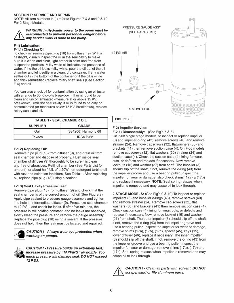
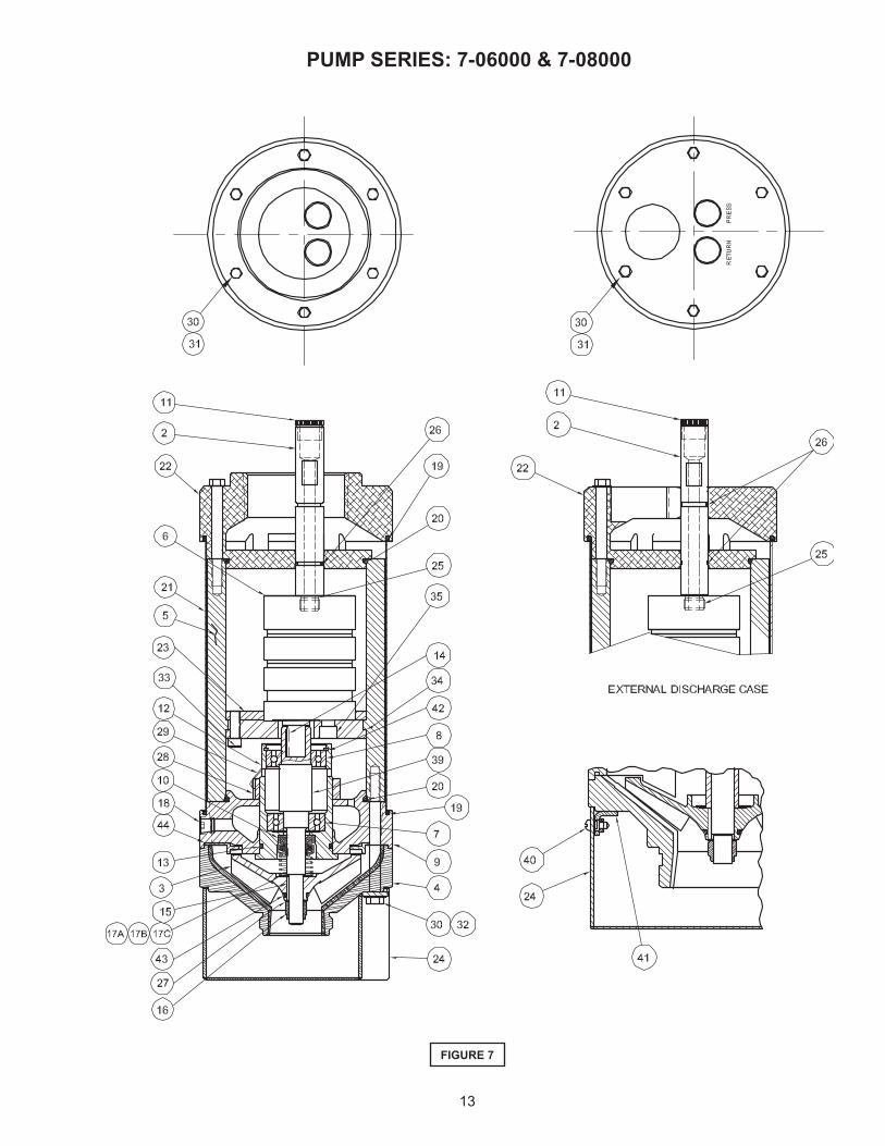
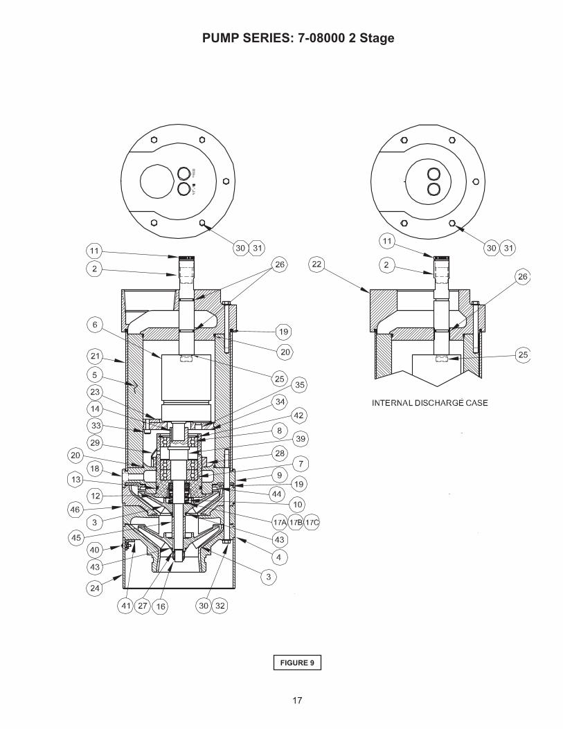
SECTION F: SERVICE AND REPAIRNOTE: All item numbers in ( ) refer to Figures 7 & 8 and 9 & 10 For 2 Stage Models.
WARNING ! - Hydraulic power to the pump must be disconnected to prevent personnel danger before any service work is done to the pump.
F-1) Lubrication:F-1.1) Checking Oil:To check oil, remove pipe plug (18) from diffuser (9). With a fl ashlight, visually inspect the oil in the seal cavity to make sure it is clean and clear, light amber in color and free from suspended particles. Milky white oil indicates the presence of water. If the the oil looks milky white, pour the oil out of the oil chamber and let it settle in a clean, dry container. If any water settles out in the bottom of the container or if the oil is white and thick (emulsifi ed) replace rotary shaft seals (See Section F-4) and oil.
You can also check oil for contamination by using an oil tester with a range to 30 Kilovolts breakdown. If oil is found to be clean and uncontaminated (measure at or above 15 KV. breakdown), refi ll the seal cavity. If oil is found to be dirty or contaminated (or measures below 15 KV. breakdown), replace rotary seals and oil.
TABLE 1 - SEAL CHAMBER OIL
SUPPLIER GRADE
Gulf (334206) Harmony 68
Texaco URSA P-68
F-1.2) Replacing Oil:
Remove pipe plug (18) from diffuser (9), and drain oil from
seal chamber and dispose of properly. Flush inside seal
chamber of diffuser (9) thoroughly to be sure it is clean
and free of abrasives. Refi ll oil chamber (See Parts List for
amount), or about half full, of a 20W non-detergent turbine oil
with rust and oxidation inhibitors, See Table 1. After replacing
oil, replace pipe plug (18) using a sealant.
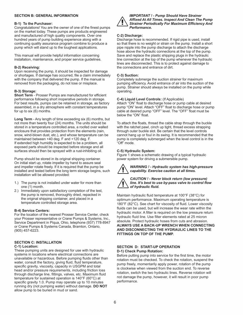
F-1.3) Seal Cavity Pressure Test:
Remove pipe plug (18) from diffuser (9) and check that the
seal chamber is of the correct amount of oil (See Figure 2).
Apply pipe sealant to pressure gauge assembly and tighten
into hole in Intermediate diffuser (9). Pressurize seal chamber
to 12 P.S.I. and check for leaks. If after fi ve minutes, the
pressure is still holding constant, and no leaks are observed,
slowly bleed the pressure and remove the gauge assembly.
Replace the pipe plug (18) using a sealant. If the pressure
does not hold, then the leak must be located and repaired.
CAUTION ! - Always wear eye protection when
working on pumps.
CAUTION ! - Pressure builds up extremely fast,
increase pressure by “TAPPING” air nozzle. Too
much pressure will damage seal. DO NOT exceed
12 P.S.I.
F-2) Impeller Service:
F-2.1) Disassembly: - (See Fig’s 7 & 8)
On 7-08 single stage models, to inspect or replace impeller
(3) and impeller o-ring (43), remove screws (40) and remove
strainer (24). Remove capscrews (32), fl atwashers (30) and
brackets (41) then remove suction case (4). On 7-06 models,
remove capscrews (32), fl at washers (30) strainer (24) and
suction case (4). Check the suction case (4) lining for wear,
cuts, or defects and replace if necessary. Now remove
locknuts (16) and washer (27) from shaft. The impeller (3)
should slip off the shaft, if not, remove the o-ring (43) from
the impeller groove and use a bearing puller. Inspect the
impeller for wear or damage, also check shims (17a) & (17b)
and replace if necessary. NOTE: Seal spring relaxes when
impeller is removed and may cause oil to leak through.
2-STAGE MODELS: (See Fig’s 9 & 10) To inspect or replace
impellers (3) and impeller o-rings (43), remove screws (40)
and remove strainer (24). Remove cap screws (32), fl at
washers (30) and brackets (41) then remove suction case (4).
Check suction case (4) lining for wear, cuts, or defects and
replace if necessary. Now remove locknut (16) and washer
(27) from shaft. The outer impeller (3) should slip off the shaft,
if not, remove the o-ring (43) from the impeller groove and
use a bearing puller. Inspect the impeller for wear or damage,
remove shims (17a), (17b), (17c), spacer (45), keys (15),
lower diffuser (46), replace if necessary. The inner impeller
(3) should slip off the shaft, if not, remove the o-ring (43) from
the impeller groove and use a bearing puller. Inspect the
impeller for wear or damage, remove shims (17a), (17b) and
(17c). Seal spring relaxes when impeller is removed and may
cause oil to leak through.
CAUTION ! - Clean all parts with solvent. DO NOT
scrape, sand or fi le aluminum parts.
FIGURE 2
9
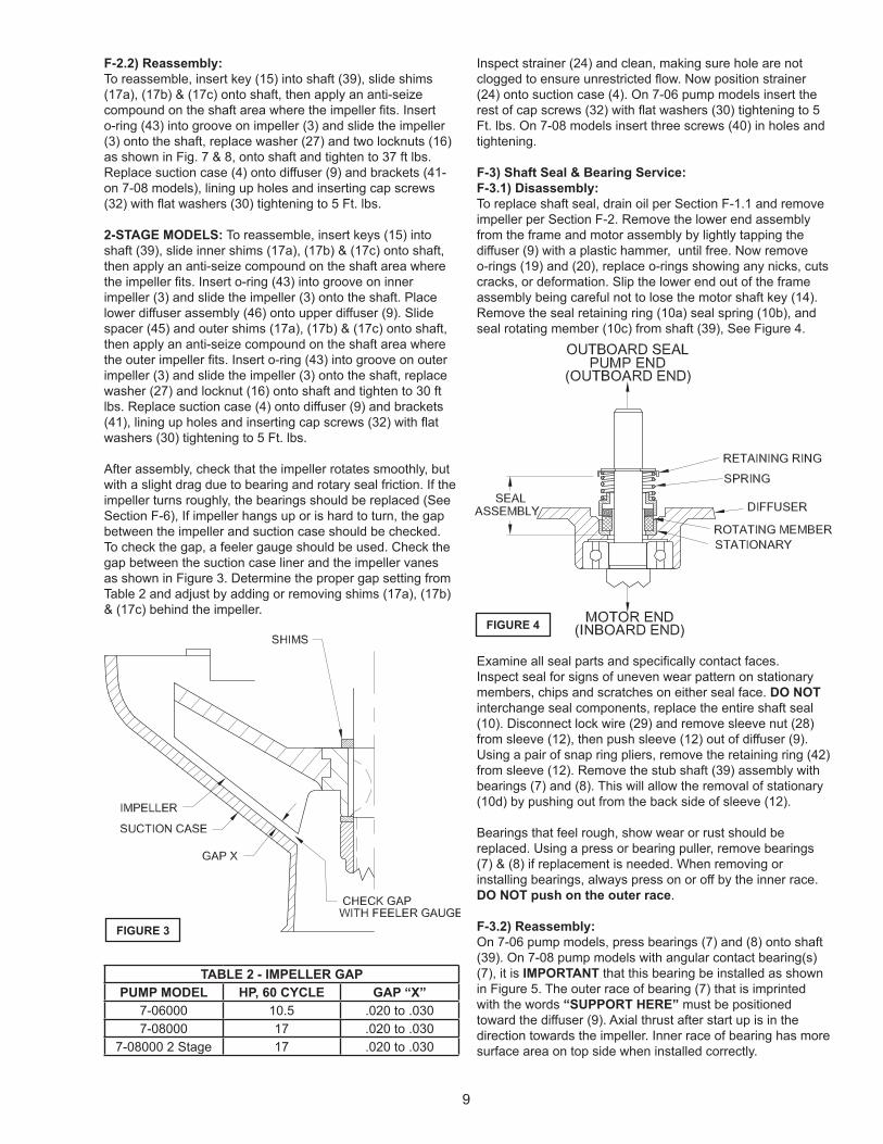
F-2.2) Reassembly:
To reassemble, insert key (15) into shaft (39), slide shims
(17a), (17b) & (17c) onto shaft, then apply an anti-seize
compound on the shaft area where the impeller fi ts. Insert
o-ring (43) into groove on impeller (3) and slide the impeller
(3) onto the shaft, replace washer (27) and two locknuts (16)
as shown in Fig. 7 & 8, onto shaft and tighten to 37 ft lbs.
Replace suction case (4) onto diffuser (9) and brackets (41-
on 7-08 models), lining up holes and inserting cap screws
(32) with fl at washers (30) tightening to 5 Ft. lbs.
2-STAGE MODELS: To reassemble, insert keys (15) into
shaft (39), slide inner shims (17a), (17b) & (17c) onto shaft,
then apply an anti-seize compound on the shaft area where
the impeller fi ts. Insert o-ring (43) into groove on inner
impeller (3) and slide the impeller (3) onto the shaft. Place
lower diffuser assembly (46) onto upper diffuser (9). Slide
spacer (45) and outer shims (17a), (17b) & (17c) onto shaft,
then apply an anti-seize compound on the shaft area where
the outer impeller fi ts. Insert o-ring (43) into groove on outer
impeller (3) and slide the impeller (3) onto the shaft, replace
washer (27) and locknut (16) onto shaft and tighten to 30 ft
lbs. Replace suction case (4) onto diffuser (9) and brackets
(41), lining up holes and inserting cap screws (32) with fl at
washers (30) tightening to 5 Ft. lbs.
After assembly, check that the impeller rotates smoothly, but
with a slight drag due to bearing and rotary seal friction. If the
impeller turns roughly, the bearings should be replaced (See
Section F-6), If impeller hangs up or is hard to turn, the gap
between the impeller and suction case should be checked.
To check the gap, a feeler gauge should be used. Check the
gap between the suction case liner and the impeller vanes
as shown in Figure 3. Determine the proper gap setting from
Table 2 and adjust by adding or removing shims (17a), (17b)
& (17c) behind the impeller.
TABLE 2 - IMPELLER GAP
PUMP MODEL HP, 60 CYCLE GAP “X”
7-06000 10.5 .020 to .030
7-08000 17 .020 to .030
7-08000 2 Stage 17 .020 to .030
Inspect strainer (24) and clean, making sure hole are not
clogged to ensure unrestricted fl ow. Now position strainer
(24) onto suction case (4). On 7-06 pump models insert the
rest of cap screws (32) with fl at washers (30) tightening to 5
Ft. lbs. On 7-08 models insert three screws (40) in holes and
tightening.
F-3) Shaft Seal & Bearing Service:
F-3.1) Disassembly:
To replace shaft seal, drain oil per Section F-1.1 and remove
impeller per Section F-2. Remove the lower end assembly
from the frame and motor assembly by lightly tapping the
diffuser (9) with a plastic hammer, until free. Now remove
o-rings (19) and (20), replace o-rings showing any nicks, cuts
cracks, or deformation. Slip the lower end out of the frame
assembly being careful not to lose the motor shaft key (14).
Remove the seal retaining ring (10a) seal spring (10b), and
seal rotating member (10c) from shaft (39), See Figure 4.
Examine all seal parts and specifi cally contact faces.
Inspect seal for signs of uneven wear pattern on stationary
members, chips and scratches on either seal face. DO NOT
interchange seal components, replace the entire shaft seal
(10). Disconnect lock wire (29) and remove sleeve nut (28)
from sleeve (12), then push sleeve (12) out of diffuser (9).
Using a pair of snap ring pliers, remove the retaining ring (42)
from sleeve (12). Remove the stub shaft (39) assembly with
bearings (7) and (8). This will allow the removal of stationary
(10d) by pushing out from the back side of sleeve (12).
Bearings that feel rough, show wear or rust should be
replaced. Using a press or bearing puller, remove bearings
(7) & (8) if replacement is needed. When removing or
installing bearings, always press on or off by the inner race.
DO NOT push on the outer race.
F-3.2) Reassembly:
On 7-06 pump models, press bearings (7) and (8) onto shaft
(39). On 7-08 pump models with angular contact bearing(s)
(7), it is IMPORTANT that this bearing be installed as shown
in Figure 5. The outer race of bearing (7) that is imprinted
with the words “SUPPORT HERE” must be positioned
toward the diffuser (9). Axial thrust after start up is in the
direction towards the impeller. Inner race of bearing has more
surface area on top side when installed correctly.
FIGURE 4
FIGURE 3

10
When installed correctly, there will be movement upward in
shaft assembly. This is opposite of downward thrust which
occurs when pump is running. “LOOSENESS” between inner
and outer race is normal for angular contact bearing. Bearing
failure will result in a short period of time if it is not installed
as specifi ed.
Clean oil cavity in sleeve (12). Lightly oil (DO NOT use
grease) outer surface of stationary member (10d). Press
stationary member (10d) fi rmly into sleeve (12), using a seal
pusher (see Parts List - seal tool kit). Nothing but the seal
pusher is to come in contact with the seal face. Make sure
the stationary member is in straight. (See Figure 6A). Slide
sleeve (12) over shaft and bearing assembly. Insert retaining
ring (42) into sleeve (12). Check o-ring (13) on sleeve (12)
and replace if damaged. Assemble sleeve nut (28) onto
sleeve (12) and tighten. Now connect lock wire (29) to sleeve
and nut. Slide sleeve and bearing assembly into diffuser (9)
being careful not to damage o-ring (13).
CAUTION ! - Handle seal parts with extreme care.
DO NOT scratch or mar lapped surfaces.
IMPORTANT ! - DO NOT hammer on the seal
pusher- it will damage the seal face.
Slide a bullet (see parts list-seal tool kit) over stub shaft
(39). Lightly oil (DO NOT use grease) shaft, bullet and inner
surface of bellows on rotating member (10c). With lapped
surface of rotating member (10c) facing inward toward
stationary member (10d), slide rotating member (10c) over
bullet and onto shaft, using seal pusher, until lapped faces of
(10d) and (10c) are together (see Figure 6B).
IMPORTANT ! - It is extremely important to keep
seal faces clean during assembly. Dirt particles
lodged between these faces will cause the seal to
leak.
Place spring (10b) over shaft and in place on rotating
member (10c), making sure it is seated on retainer and not
cocked or resting on bellows tail. Slide retaining ring (10a) over shaft and let rest on spring (10b). (See Figure 6C). NOTE: When installing the seal retainer over shaft, do not scratch the shaft or seal seat face. Assemble impeller, suction case and screen per Section F-3.2. Replace oil as outlined in paragraph F-2.2.
F-4) Discharge and Motor Service:F-4.1) Disassembly:Refer to Section F-1 before disassembly. Check for indications of water leaks before the pump has a chance to dry out. Disassemble suction end of pump per Sections F-2 & F-3. Remove cap screws (31) and washers (30), hydraulic fi ttings (2) and o-rings (25) and (26) from discharge head (22). Use care to avoid damaging the metal surface. Use the fl ats provided on the hydraulic fi ttings for removal. Carefully, using a plastic hammer, tap the discharge case (22) free from the frame assembly and remove. Now remove o-rings (19) and (20), replace o-rings showing any nicks, cuts, cracks, or deformation. Visually check the area around the hydraulic motor (6) for oil or water.
FIGURE 5
FIGURE 6

11
The three recessed head cap screws (33) can now be
removed from the motor mounting plate (34). Remove the
mounting plate (34), hydraulic motor (6) and retainer (23). If
motor (6) is being replaced, remove mounting plate (34) by
removing screws (35).
F-4.2) Reassembly:
Assemble motor (6) to mounting plate (34) by inserting
screws (35) into the inner two holes and tightening. Insert
motor and mounting plate into frame (5). Place retainer (23)
onto mounting plate from the opposite end of frame (5) and
insert three screws (33) in the outer holes and tighten. To
assemble discharge case (22) to frame (5), set the assembly
in the upright position. Apply a grease to o-rings (19) and
(20) and place discharge case (22) onto the frame assembly
lining up the holes. Insert cap screws (31) with washers
(30), into holes and torque to 75 In Lbs. Place o-rings (25)
and (26) in the appropriate locations (see Fig,s 7 or 9, for
internal or external operation), on the hydraulic fi ttings (2).
Insert hydraulic fi ttings (2), through discharge case (22) and
into motor (6) and tighten, by placing wrench on the fl ats
located on fi tting. Assemble lower end of pump per Sections
F-3 and F-2.
SECTION: G REPLACEMENT PARTS
G-1 ORDERING REPLACEMENT PARTS:
Your local Prosser distributor can supply parts and repair
service. When ordering parts, ALWAYS furnish the following
information: Specify pump model number as shown on
nameplate, serial number, part number, item number and part
name.
1. Pump serial number. (G-1)
2. Pump model number. (G-2)
3. Part description.
4. Item part number.
5. Quantity required.
6. Shipping instructions.
7. Billing Instructions.
G-1 SERIAL NUMBER:
The Serial Number block will consists of a six digit number,
which is specifi c to each pump and may be preceded by
a alpha character, which indicates the plant location. This
number will also be suffi xed with a three or four digit number,
which indicates the date the unit was built (Date Code).
EXAMPLE: A012345 495
Reference the six digit portion (Serial Number) of the number
when referring to the product.
G-2 MODEL NUMBER:
This designation consist of numbers which represent, Pump
Line, Horsepower, Motor phase, Voltage and Variations
(as shown below). This Number is used for ordering and
obtaining information.
12
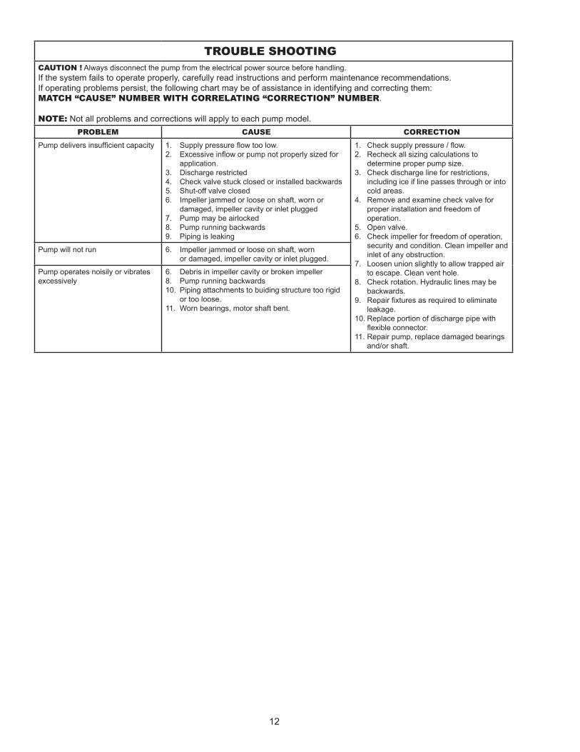
TROUBLE SHOOTING
CAUTION ! Always disconnect the pump from the electrical power source before handling.
If the system fails to operate properly, carefully read instructions and perform maintenance recommendations.
If operating problems persist, the following chart may be of assistance in identifying and correcting them:
MATCH “CAUSE” NUMBER WITH CORRELATING “CORRECTION” NUMBER.
NOTE: Not all problems and corrections will apply to each pump model.
PROBLEM CAUSE CORRECTION
Pump delivers insuffi cient capacity 1. Supply pressure fl ow too low.
2. Excessive infl ow or pump not properly sized for
application.
3. Discharge restricted
4. Check valve stuck closed or installed backwards
5. Shut-off valve closed
6. Impeller jammed or loose on shaft, worn or
damaged, impeller cavity or inlet plugged
7. Pump may be airlocked
8. Pump running backwards
9. Piping is leaking
1. Check supply pressure / fl ow.
2. Recheck all sizing calculations to
determine proper pump size.
3. Check discharge line for restrictions,
including ice if line passes through or into
cold areas.
4. Remove and examine check valve for
proper installation and freedom of
operation.
5. Open valve.
6. Check impeller for freedom of operation,
security and condition. Clean impeller and
inlet of any obstruction.
7. Loosen union slightly to allow trapped air
to escape. Clean vent hole.
8. Check rotation. Hydraulic lines may be
backwards.
9. Repair fi xtures as required to eliminate
leakage.
10. Replace portion of discharge pipe with
fl exible connector.
11. Repair pump, replace damaged bearings
and/or shaft.
Pump will not run 6. Impeller jammed or loose on shaft, worn
or damaged, impeller cavity or inlet plugged.
Pump operates noisily or vibrates
excessively
6. Debris in impeller cavity or broken impeller
8. Pump running backwards
10. Piping attachments to buiding structure too rigid
or too loose.
11. Worn bearings, motor shaft bent.
13
FIGURE 7
PUMP SERIES: 7-06000 & 7-08000

14
FIGURE 8
PUMP SERIES: 7-06000 & 7-08000

15
PARTS KITS
Seal Tool Kit...............T/L - 21355
PARTS LIST
ITEM QTY PART NO. DESCRIPTION
1 1 2-33037 Name Plate
2 2 7-060811 Hydraulic Fitting
3 1 615026B-5 Impeller, Stainless, 3.56” Dia.
4 1 615170 Suction Case, Aluminum
5 1 7-060500 Frame, Aluminum
6 1 7-060600 Hydraulic Motor 10.5HP, 2000PSI
7 1 2-34010 Ball Bearing, Lower
8 1 2-34011 Ball Bearing, Upper
9 1 7-060300 Diffuser
10 1 2-31036 Shaft Seal C/CE/B
11 2 2-32043-3 Pipe Plug, Poly. 3/8 NPT
12 1 7-060303 Sleeve
13 1 2-31003-133 O-Ring Buna-N, 1.799” ID
14 1 625-00677 Key .13 x .13 x .75
15 1 7-060410 Key .09 x .13 x .625
16 1 2-12015-2 Lock Nut, Impeller 3/8-24, Stainless
17a A/R 2-21002-64 Flat Washer, (.016) 3/8” Stainless
17b A/R 2-21002-65 Flat Washer, (.032) 3/8” Stainless
17c A/R 2-21012-1 Flat Washer, (.005) 3/8” Stainless
18 1 2-32004-8 Pipe Plug .125 NPT. Stainless
19 2 2-31003-158 O-Ring Buna-N, 4.737” ID
20 2 2-31003-239 O-Ring Buna-N, 3.609” ID
21 1 615017 Outer Shell
22 1 7-061700 Discharge Case, External 7-06106-020 / 1.5”
1 7-062700 Discharge Case, Internal 7-06206-020 / 2.5”
23 1 7-060502 Retainer Mounting Plate
24 1 9-100000-4 Strainer Stainless Steel
25 2 2-31015-6 O-Ring Buna-N, .078” ID
26 4 2-31003-016 O-Ring Buna-N, .614” ID
27 1 550048 Lock Washer, Impeller 3/8” Stainless
28 1 7-060311 Sleeve Nut #2-16, Steel
29 1 MS20995-C32 Lock Wire Stainless
30 12 2-21002-11 Flat Washer 1/4”, ZP
31 6 2-23007-10 Hex Hd Cap Screw 1/4-20 x 2.50”, ZP
32 6 2-23013-28 Hex Hd Cap Screw 1/4-20 x 3.00”, ZP
33 3 2-23025-25 Socket Hd Screw 1/4-20 x .75
34 1 7-060501 Mounting Plate
35 2 2-23025-18 Socket Hd Screw 5/16-18 x .625
37 6 2-28002-3 Rivet
38 8 oz. A3195AB Oil, Navy 7-06106-020
39 1 7-060403 Stub Shaft Stainless
42 1 2-27006-165 Retainer Ring 1.650” OD
43 1 2-31003-113 O-Ring, Impeller Buna-N, .549” ID
PUMP SERIES: 7-06000

16
PARTS KITS
Seal Tool Kit...............T/L - 21355
PARTS LIST
ITEM QTY PART NO. DESCRIPTION 1 1 2-33037 Name Plate 2 2 7-080810 Hydraulic Fitting 7-08306/08406 2 7-080811 Hydraulic Fitting 7-08312/08412 3 1 9-603200-1 Impeller, 5.31” Dia., Stainless 7-08306/08406 1 9-605200-1 Impeller, 5.31” Dia., Stainless 7-08312/08412 4 1 9-2501000-1 Suction Case, Aluminum 7-08306/08406 1 9-500100-1 Suction Case, Aluminum 7-08312/08412 5 1 7-080500 Frame, Aluminum 6 1 7-060600 Hydraulic Motor, 7-08306/08406 10.5HP, 2000PSI 1 7-080600 Hydraulic Motor, 7-08312/08412 17HP, 2000PSI 7 1 2-34008 Ball Bearing, Lower 8 1 2-34009 Ball Bearing, Upper 9 1 7-080300-2 Diffuser 10 1 9-605350 Shaft Seal Silicon/Silicon/Viton® 11 2 2-32043-3 Pipe Plug, Poly. 3/8” NPT 12 1 7-080303 Sleeve 13 1 2-31003-149 O-Ring Buna-N, 2.80” ID 14 1 625-00677 Key, 7-08306/08406 .13 x .13 x .75 1 7-080409 Key, 7-08312/08412 .19 x .19 x 1.0 15 1 9-500407 Key .09 x .13 x .688 16 1 2-20002-38 Lock Nut, Impeller 1/2-20 Stainless 17a A/R 2-21003-34 Flat Washer, (.016) 5/8” Stainless 17b A/R 2-21003-35 Flat Washer, (.032) 5/8” Stainless 17c A/R 2-21012-2 Flat Washer, (.005) .632” Stainless 18 1 2-32004-12 Pipe Plug .25” NPT, Stainless 19 2 2-31003-260 O-Ring Buna-N, 6.484” ID 20 2 2-31003-246 O-Ring Buna-N, 4.484” ID 21 1 9-250555 Outer Shell 22 1 7-081700 Discharge Case, External 7-08306 1 7-081710 7-08312 1 7-082710 Discharge Case, Internal 7-08406 1 7-082700 7-08412 23 1 7-080504 Retainer Mounting Plate 24 1 9-500000-1 Strainer Stainless Steel 25 2 2-31015-6 O-Ring, 7-08306/08406 Buna-N, .078” ID 2 2-31015-8 O-Ring, 7-08312/08412 Buna-N, .064” ID 26 4 2-31003-016 O-Ring, 7-08306/08406 Buna-N, .614” ID 2-31003-117 O-Ring, 7-08312/08412 Buna-N, .799” ID 27 1 9-815211 Lock Washer, Impeller .51 x 1.20 Stainless 28 1 7-080311 Sleeve Nut #3-12 Steel 29 1 MS20995-C32 Lock Wire Stainless 30 11 2-21002-14 Flat Washer 5/16”, ZP 31 5 2-23007-11 Hex Hd Cap Screw 5/16-18 x 2.50”, ZP 32 6 1-172-1 Hex Hd Cap Screw, 7-08306/08406 5/16-18 x 3.25”, Stainless 6 2-23007-47 Hex Hd Cap Screw, 7-08312/08412 5/16-18 x 3.50”, ZP 33 3 2-23025-25 Socket Hd Screw 1/4-20 x .750”, Stainless 34 1 7-080501 Mounting Plate, 7-08306/08406 1 7-080502 Mounting Plate, 7-08312/08412 35 2 2-23025-18 Socket Hd Screw 5/16-18 x .625 Stainless 37 6 2-28002-3 Rivet 38 12 oz. A3195AB Oil, Navy 39 1 7-080403 Stub Shaft, 7-08306/08406 Stainless 1 7-080404 Stub Shaft, 7-08312/08412 Stainless 40 3 2-23010-54 Pan Hd Screw 1/4-20 x .50 CAD 41 3 9-50003 Strainer Bracket 42 1 2-27006-244 Retainer Ring 43 1 2-31003-117 O-Ring, Impeller Buna-N, .799” ID 44 1 9-501305 Wear Plate Polyurethane
PUMP SERIES: 7-08000
17
PUMP SERIES: 7-08000 2 Stage
FIGURE 9

18
PUMP SERIES: 7-08000 2 Stage
FIGURE 10

19
PUMP SERIES: 7-08000 2 Stage
PARTS KITS
Seal Tool Kit...............T/L - 21355
PARTS LIST
ITEM QTY PART NO. DESCRIPTION
1 1 2-33037 Name Plate
2 2 7-080811 Hydraulic Fitting
3 2 9-550200 Impeller, 5.31” Dia., Stainless
4 1 9-550100 Suction Case, Aluminum
5 1 7-080500 Frame, Aluminum
6 1 7-080600 Hydraulic Motor, 17HP, 2000PSI
7 1 2-34020 Ball Bearing, Lower, Angular Contact, Duplex, Tandem Mounting
8 1 2-34009 Ball Bearing, Upper
9 1 7-080300-2 Diffuser, Upper
10 1 9-605350 Shaft Seal Silicon/Silicon/Viton®
11 2 2-32043-4 Pipe Plug, Poly. 1/2” NPT
12 1 7-080304 Sleeve
13 1 2-31003-149 O-Ring Buna-N, 2.80” ID
14 1 7-080409 Key .19 x .19 x 1.0
15 2 9-500407 Key, Impeller .09 x .13 x .688
16 1 2-20002-38 Lock Nut, Impeller 1/2-20 Stainless
17a A/R 2-21003-34 Flat Washer, (.016) 5/8” Stainless
17b A/R 2-21003-35 Flat Washer, (.032) 5/8” Stainless
17c A/R 2-21012-2 Flat Washer, (.005) .632” Stainless
18 1 2-32004-12 Pipe Plug .25” NPT, Stainless
19 2 2-31003-260 O-Ring Buna-N, 6.484” ID
20 2 2-31003-246 O-Ring Buna-N, 4.484” ID
21 1 9-250555 Outer Shell
22 1 7-081710 Discharge Case, External 7-08312
1 7-082700 Discharge Case, Internal 7-08412
23 1 7-080504 Retainer Mounting Plate
24 1 9-500000-1 Strainer Stainless Steel
25 2 2-31015-8 O-Ring Buna-N, .064” ID
26 4 2-31003-117 O-Ring Buna-N, .799” ID
27 1 9-815211 Lock Washer, Impeller .51 x 1.20 Stainless
28 1 7-080311 Sleeve Nut #3-12 Steel
29 1 MS20995-C32 Lock Wire Stainless
30 11 2-21002-14 Flat Washer 5/16”, ZP
31 5 2-23007-11 Hex Hd Cap Screw 5/16-18 x 2.50”, ZP
32 6 2-23013-92 Hex Hd Cap Screw 5/16-18 x 5.50”, ZP
33 3 2-23025-25 Socket Hd Screw 1/4-20 x .750”, Stainless
34 1 7-080502 Mounting Plate
35 2 2-23025-18 Socket Hd Screw 5/16-18 x .625 Stainless
37 6 2-28002-3 Rivet
38 12 oz. A3195AB Oil, Navy
39 1 7-080405 Stub Shaft Stainless
40 3 2-23010-54 Pan Hd Screw 1/4-20 x .50 CAD
41 3 9-500003 Strainer Bracket
42 1 2-27006-244 Retainer Ring
43 2 2-31003-117 O-Ring, Impeller Buna-N, .799” ID
44 1 9-501305 Wear Plate Polyurethane
45 1 9-550209 Spacer Stainless
46 1 7-080305 Diffuser, Lower

20
A Crane Co. Company
Limited 24 Month WarrantyCrane Pumps & Systems warrants that products of our manufacture will be free of defects in material and workmanship
under normal use and service for twenty-four (24) months after manufacture date, when installed and maintained
in accordance with our instructions.This warranty gives you speci� c legal rights, and there may also be other rights
which vary from state to state. In the event the product is covered by the Federal Consumer Product Warranties Law
(1) the duration of any implied warranties associated with the product by virtue of said law is limited to the same
duration as stated herein, (2) this warranty is a LIMITED WARRANTY, and (3) no claims of any nature whatsoever
shall be made against us, until the ultimate consumer, his successor, or assigns, noti� es us in writing of the defect,
and delivers the product and/or defective part(s) freight prepaid to our factory or nearest authorized service station.
Some states do not allow limitations on how long an implied warranty lasts, so the above limitation may not apply.
THE SOLE AND EXCLUSIVE REMEDY FOR BREACH OF ANY AND ALL WARRANTIES WITH RESPECT TO ANY
PRODUCT SHALL BE TO REPLACE OR REPAIR AT OUR ELECTION, F.O.B. POINT OF MANUFACTURE OR
AUTHORIZED REPAIR STATION, SUCH PRODUCTS AND/OR PARTS AS PROVEN DEFECTIVE. THERE SHALL BE
NO FURTHER LIABILITY, WHETHER BASED ON WARRANTY, NEGLIGENCE OR OTHERWISE. Unless expressly
stated otherwise, guarantees in the nature of performance speci� cations furnished in addition to the foregoing material
and workmanship warranties on a product manufactured by us, if any, are subject to laboratory tests corrected for
� eld performance. Any additional guarantees, in the nature of performance speci� cations must be in writing and such
writing must be signed by our authorized representative. Due to inaccuracies in � eld testing if a con! ict arises between
the results of � eld testing conducted by or for user, and laboratory tests corrected for � eld performance, the latter
shall control. RECOMMENDATIONS FOR SPECIAL APPLICATIONS OR THOSE RESULTING FROM SYSTEMS
ANALYSES AND EVALUATIONS WE CONDUCT WILL BE BASED ON OUR BEST AVAILABLE EXPERIENCE AND
PUBLISHED INDUSTRY INFORMATION. SUCH RECOMMENDATIONS DO NOT CONSTITUTE A WARRANTY OF
SATISFACTORY PERFORMANCE AND NO SUCH WARRANTY IS GIVEN.
This warranty shall not apply when damage is caused by (a) improper installation, (b) improper voltage (c) lightning
(d) excessive sand or other abrasive material (e) scale or corrosion build-up due to excessive chemical content. Any
modi� cation of the original equipment will also void the warranty. We will not be responsible for loss, damage or labor
cost due to interruption of service caused by defective parts. Neither will we accept charges incurred by others without
our prior written approval.
This warranty is void if our inspection reveals the product was used in a manner inconsistent with normal industry practice
and\or our speci� c recommendations. The purchaser is responsible for communication of all necessary information
regarding the application and use of the product. UNDER NO CIRCUMSTANCES WILL WE BE RESPONSIBLE FOR
ANY OTHER DIRECT OR CONSEQUENTIAL DAMAGES, INCLUDING BUT NOT LIMITED TO TRAVEL EXPENSES,
RENTED EQUIPMENT, OUTSIDE CONTRACTOR FEES, UNAUTHORIZED REPAIR SHOP EXPENSES, LOST
PROFITS, LOST INCOME, LABOR CHARGES, DELAYS IN PRODUCTION, IDLE PRODUCTION, WHICH DAMAGES
ARE CAUSED BY ANY DEFECTS IN MATERIAL AND\OR WORKMANSHIP AND\OR DAMAGE OR DELAYS IN
SHIPMENT. THIS WARRANTY IS EXPRESSLY IN LIEU OF ANY OTHER EXPRESS OR IMPLIED WARRANTY,
INCLUDING ANY WARRANTY OF MERCHANTABILITY OR FITNESS FOR A PARTICULAR PURPOSE.
No rights extended under this warranty shall be assigned to any other person, whether by operation of law or otherwise,
without our prior written approval.
420 Third Street 83 West Drive
Piqua, Ohio 45356 Brampton, Ont. Canada L6T 2J6
(937) 778-8947 (905) 457-6223
Fax (937) 773-7157 Fax (905) 457-2650
www.cranepumps.com
21
RETURNED GOODS
RETURN OF MERCHANDISE REQUIRES A “RETURNED GOODS AUTHORIZATION”.
CONTACT YOUR LOCAL CRANE PUMPS & SYSTEMS, INC. DISTRIBUTOR.
Products Returned Must Be Cleaned, Sanitized,
Or Decontaminated As Necessary Prior To Shipment,
To Insure That Employees Will Not Be Exposed To Health
Hazards In Handling Said Material. All Applicable Laws
And Regulations Shall Apply.
IMPORTANT!
WARRANTY REGISTRATION
Your product is covered by the enclosed Warranty.
To complete the Warranty Registration Form go to:
http://www.cranepumps.com/ProductRegistration/
If you have a claim under the provision of the warranty, contact your local
Crane Pumps & Systems, Inc. Distributor.

22
Notes