DESIGN OF CAMBERED AEROFOIL FOR UNMANNED AERIAL VEHICLE BASED ON SUBSONIC WIND TUNNEL TEST
NASA/TMn1998-206636
Propulsion System for Very High AltitudeSubsonic Unmanned Aircraft
David J. Bents, Ted Mockler, and Jaime Maldonado
Lewis Research Center, Cleveland, Ohio
James L. Harp, Jr. and Joseph F. King
ThermoMechanical Systems Inc., Canoga Park, California
Paul C. Schmitz
Power Computing Solutions Inc., Avon, Ohio
Prepared for the
Aerospace Power Systems "98
sponsored by the Society of Automotive Engineers
Williamsburg, Virginia, April 21-23, 1998
National Aeronautics and
Space Administration
Lewis Research Center
April 1998
https://ntrs.nasa.gov/search.jsp?R=19980137599 2020-04-11T12:16:09+00:00Z

NASA Center for Aerospace Information800 Elkridge Landing Road
Linthicum Heights, MD 21090-2934Price Code: A03
Available from
National Technical Information Service
5287 Port Royal Road
Springfield, VA 22100Price Code: A03
Propulsion System for Very High Altitude Subsonic UnmannedAircraft
David J. Bents, Ted Mockler, and Jaime MaldonadoNASA Lewis Research Center
James L. Harp Jr. and Joseph F. KingThermoMechanical Systems Inc.
Paul C. Schmitz
Power Computing Solutions Inc.
ABSTRACT
This paper explains why a spark ignited gasolineengine, intake pressurized with three cascaded stagesof turbocharging, was selected to power NASA'scontemplated next generation of high altitudeatmospheric science aircraft. Beginning with the mosturgent science needs (the atmospheric samplingmission) and tracing through the mission requirementswhich dictate the unique flight regime in which thisaircraft has to operate (subsonic flight @ >80 kft) we
briefly explore the physical problems and constraints,the available technology options and the cost driversassociated with developing a viable propulsion systemfor this highly specialized aircraft. The paper presentsthe two available options (the turbojet and theturbocharged spark ignited engine) which arediscussed and compared in the context of the flightregime. We then show how the unique nature of thesampling mission, coupled with the economicconsiderations pursuant to aero engine development,point to the spark ignited engine as the only costeffective solution available. Surprisingly, this solutioncompares favorably with the turbojet in the flightregime of interest. Finally, some remarks are madeabout NASA's present state of development, andfuture plans to flight demonstrate the three stageturbocharged powerplant.
INTRODUCTION
Because of the increasing influence of man-made
pollutants and their potential impact on Earth'satmosphere, the science community is expendingconsiderable effort to gain a better understanding ofits detailed chemistry and dynamics. Much of the workinvolves the development of more sophisticatedcomputer models of the atmosphere. These arevalidated through correlations with observed data,which includes both remote sensing and in situ
measurements. At present, the highest prioritymeasurements are in situ measurements at altitudesabove 73 kft to over 80 kft, especially within 12 ° of
the Equator. The in situ measurements are hardest toobtain since they involve physical samples taken byairborne instruments. Aircraft are the preferredinstrument platform because of the length anddirectedness of the flightpath, which allows largenumbers of samples to be obtained at specifiedlocations in the atmosphere, at the specific times
dictated by science opportunity.
The most urgent need is for an aircraft that can fly
long distances at altitudes significantly above 80 kft.The aircraft presently used for sampling, even the
high altitude ER-2, are not capable of flying muchhigher than 73 kft. While balloon borne instrumentscan reach altitudes as high as 130 kft, the undirectednature of balloon flight limits the geographic coverageand spatial resolution that is needed (the coverageachieved by a single airplane flight is the equivalent of10--100 simultaneous balloon flights). There are a
limited number of supersonic aircraft capable of flyingover 80 kft, but these aircraft achieve high altitude by
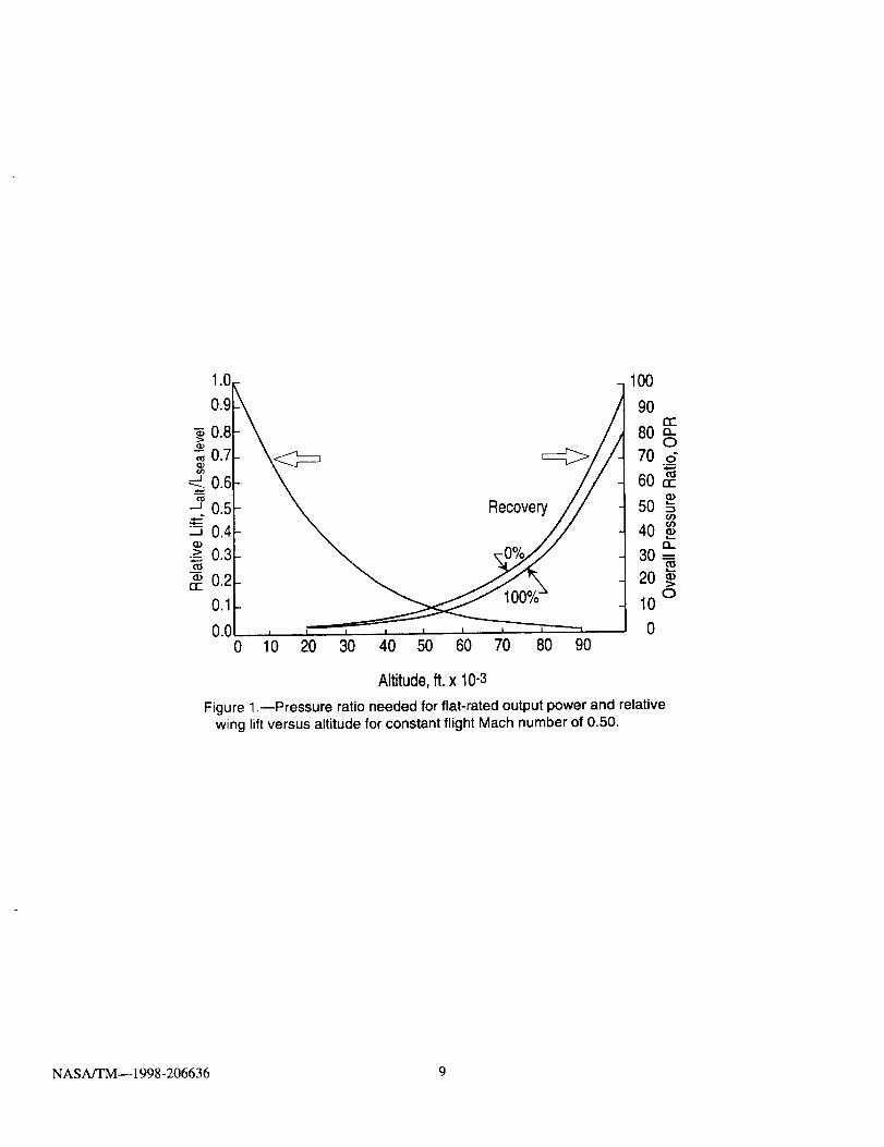
flying supersonically. The aerodynamic heating andshock associated with supersonic flight causechanges to the air sample which negate themeasurements being made. The airplane whichperforms the sampling mission must be subsonic.This presents a contradiction--the most straight-forward way to achieve high altitudes is to fly fast, butthis airplane must fly high and slow--a very difficultthing to achieve. Because of the exponential lapse ofair density with altitude, a subsonic aircraft flying at80 kft altitudes cannot generate much lift (see Fig. 1).Even at reasonably high speeds (M = 0.5) the
dynamic pressure available limits wing Ioadings to only7 to 12 psf; more like a sailplane than a poweredaircraft.
THE PROPULSION CHALLENGE
It is widely acknowledged that the propulsionsystem is the most difficult technical challenge.Whether it is manned or unmanned, an aircraft
designed to fly subsonically >80 kft for >4 hrs will
NASA/TM--1998-206636 1
require a propulsion system that is quite different fromexisting systems. Because of range and flightduration, air breathing propulsion is required. In thisflight regime, however, air breathing propulsion isdifficult to achieve. The difficulty arises from theexponential lapse of air density and pressure withaltitude. At 80 kft the ambient air density and pressureare about 1/30th of sea level values. As Fig. 1 shows,subsonic forward speeds do not generate much inletpressurization (at 80 kft, M = 0.5, less than 10 psf isavailable). Therefore, turbomachinery is needed tosupply most of the intake pressurization required tocompress ambient air into a powerplant working fluidof reasonable density.
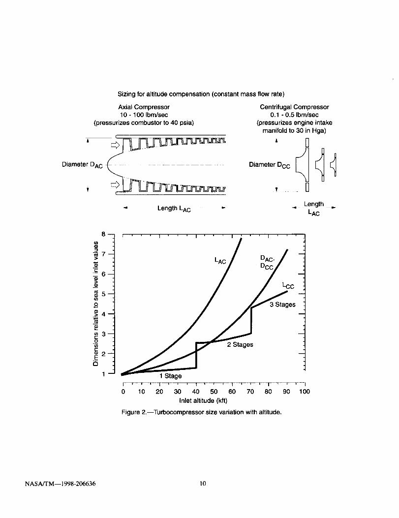
To pressurize the intake to 1 atm at 80 kft, anoverall pressure ratio (OPR) better than 36:1 isrequired. Several turbomachinery stages are neededfor intake pressurization. For example, at least 3centrifugal compressor stages are required to providean OPR of 30 to 40; more if an axial compressor isused. Because of low inlet density, theturbomachinery is large in size, especially the firststage. Volume flow (corrected flow) requirementsincrease with altitude, which translates to largerturbomachinery diameters. Pressure ratiorequirements also increase with altitude, whichtranslates to more turbomachinery stages. Sincepower is proportional to airflow for any air breathingengine, the machinery size required to process airflowfor a given rated power will grow with altitude as OPRand corrected flow are increased. Figure 2 illustrateshow machine diameter and length must change asOPR and corrected flow are increased to compensatefor altitude. Two turbo-machines are shown. One is anaxial flow unit typical of a turbojet engine, pressurizinga 40 psia combustor flowing a constant 100 Ibm/sec.The other is a centrifugal unit common toreciprocating engine turbochargers, maintaining aconstant 30 in HgA manifold pressure and flowing0.2 Ibm/sec. Both machines are compressing fromaltitude ambient conditions at the inlet (US Std.Atmosphere). Interstage cooling is assumed forboth, and consistent tip speed limits and inlet flowvelocities are observed for each machine type. Notehow machine dimensions must increase as the inletconditions are changed from sea level to 90,000 ft.For either unit, length increases more than 5 timeswhile diameter increases more than sevenfold. Weightis proportional to the cube of linear dimensions.
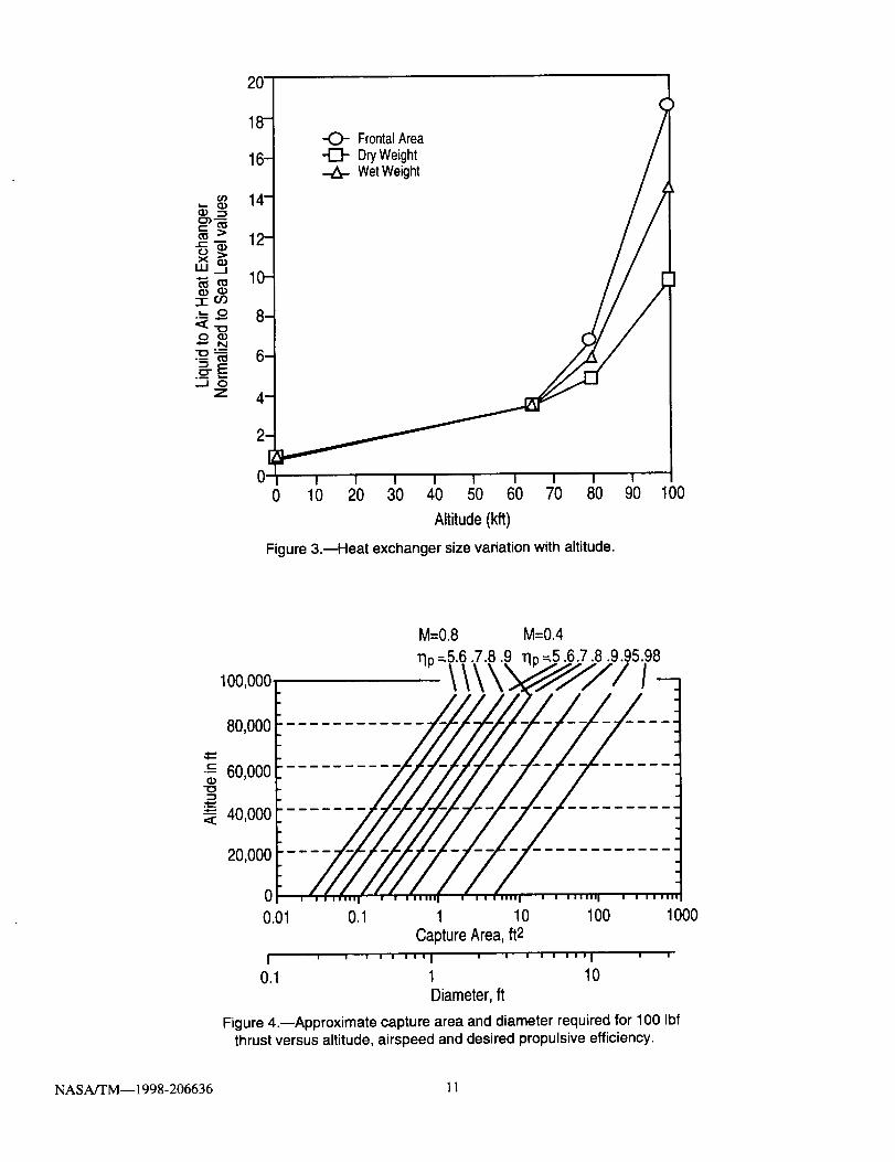
The atmospheric density lapse causes the needfor very large heat exchangers. The density lapsefrom sea level to 80 kft produces a five fold decreasein Reynolds number (Re) and more than tenfolddecrease in convective heat transfer. Heat exchangersizing is driven upwards by three factors: (a) reducedconvective heat transfer available, (b) the lowerdensity ambient air has less heat capacity, and (c)
the need for more heat rejection, due to the increasedcompression heat loads associated with higher OPR'sFor example, Fig. 3 shows how the weight and frontalarea of a typical aircraft engine coolant heatexchanger must increase to reject the same heat loadat altitude versus a sea level unit (including the effectsof reduced air temperature with altitude ).
Flying subsonically in low density air also createsthe requirement for larger thruster "capture area" or"actuator disk" areas in order to achieve reasonablepropulsive efficiencies that are needed to reduce fuelconsumption and provide range. Figure 4 shows therelationship between the minimum thruster "capturearea" needed to maintain 100 Ibf thrust versus altitude(US Std. Atmosphere), for a given propulsiveefficiency. Two representative airspeeds areillustrated. Mach 0.8 represents the approximateupper speed limit for a subsonic jet aircraft, whileMach 0.4 represents a slower aircraft speed thatreduces fuel burn. At 80 kft and M = 0.8, a 50 percentpropulsive efficiency requires at least 1 _ capturearea, which is equivalent to the nozzle exit of a smallturbojet. If capture area can be raised to 8 ft2,however (equivalent to a turbofan engine), propulsiveefficiency improves to 90 pct. At the slower speed ofM = 0.4, the same 8 _ capture area would produceonly 70 pct efficiency--to regain 90 pct efficiency thecapture area has to be increased to at least 30 _ (i.e.a propellermnote that actual capture areas will besomewhat larger than this idealized minimum).Subsonic flight at altitudes >80 kft will favor thrusterswith relatively large actuator areas (i.e. a propellerdriven aircraft), and the actuator size (i.e. propellerdiameter) will be 2 to 3 times larger than what iscommon for a conventional aircraft.
Because of the increased size and weight of theair handling, thermal management and thrust deliverycomponents, a propulsion system designed for highaltitudes is significantly larger and heavier than its lowaltitude counterpart. Further complicating matters, thehigh altitude aircraft will need more power to stay aloftbecause of the faster flight speeds necessary (tomaintain dynamic pressure and support its weight inlow density air). The propulsion system grows in bothrating and in specific weight, which tends to claimgreater and greater fractions of the airplane's grossweight. This of course runs counter to the airplane'sability to carry the weight.
PROPULSION SYSTEM OPTIONS
The weight penalty associated with air handlingand thermal management becomes a majordiscriminator when chosing propulsion for the highaltitude aircraft. There are two powerplant candidatesto consider: turbine engines (i.e. a turbojet) andturbocharged reciprocating engines. The turbojet
NASA/TM--1998-206636 2

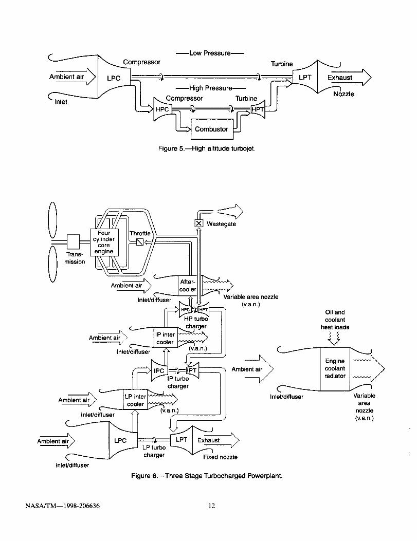
engine would be associated with a relatively highspeed (0.7<M<0.8) aircraft of conventional size withwing Ioadings in the range of sailplanes and lightaircraft (15 to 25 psf); the turbocharged reciprocatingengine would power a very large very lightlyconstructed propeller driven aircraft (M = 0.4, wingloading 4 to 7 psf) that maximizes range andendurance. Figure 5 shows a represent-ative turbineengine (turbojet); Fig. 6 shows a representativeturbocharged reciprocating engine. Both are shownconfigured for the >80 kft flight regime. As designedfor >80 kft flight, the distinctions between the twobecome somewhat blurred since the turbocharged
reciprocating engine could be considered as a variantof the turbine engine, where a reciprocating engine
has replaced the combustor core. Both require largeamounts of air, but there are major differencesbetween them concerning airflow usage. The turbine
engine ingests large amounts of air whose heat ofcompression is retained in the cycle, while theturbocharged reciprocating engine compresses only asmall fraction of the air it ingests, and uses theremainder only for heat rejection. Heat rejectionincludes what is lost to engine oil and coolant, plusthe induction air stream's heat of compression. The
turbine engine rejects almost all of its waste heat inthe cycle exhaust (which is used for for thrust), whilethe turbocharged reciprocating engine rejects asignificant fraction of its waste heat to the engine oiland coolant. Large HX's are required to removewaste heat from engine coolant and oil, and
compression heating from the induction air (but thecooling air flowing through them does not have to be
mechanically compressed).
At low altitudes, the turbine engine can generate 2to 5 times higher power density than the reciprocatingengine as long as inlet air mass flow is adequate.Mass flow is easily obtained at low altitudes where airdensities are high, and is achievable at higheraltitudes by flying at faster speeds using inletprecompression. Historically the turbine engine wasthe key to high altitude flight, since it was the firstpowerplant with high enough specific power to pushlevel flight into the supersonic range. The turbine
engine's higher fuel consumption, 1.5 to 2 times thatof the reciprocating engine, is not a disadvantage formost aircraft applications because of the higherspecific power.
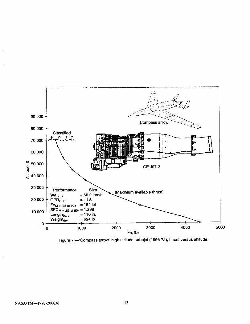
The acknowledged altitude records for subsonicflight, (shown in Table I), are dominated by turbinepowered aircraft. The highest is held by the Viet Namera AQM91 Compass Arrow spyplane, which achievedbetter than 80 kft more than 25 years ago [1].
Powered by a special design turbojet engine (shownin Fig. 7) this aircraft achieved its record altitude flying
at M = 0.83, a speed which was just enough to givethe inlet precompression needed to keep itscombustor lit. The turbine engine exhibits a specificpower that varies roughly proportional to ingested airdensity since machine size is fixed. As density dropsoff at higher altitudes, the machine ingests less airmass, resulting in reduced power and reduced thrust.Combustor pressure is correspondingly reduced;eventually to the point where combustion of hydro-carbon fuel can no longer be supported. Figure 7shows the J97's thrust lapse curve, whose behavior is
typical of all turbine engines. As an example, theCompass Arrow's J97 turbojet which was capable of>4,000 Ibf thrust at sea level, would produce only184 Ibf at 80 kft (M = 0.85) and is operating on the
verge of flameout.
The high altitude J97 engine never went into
production because Compass Arrow was ultimatelycanceled. There remain twenty-four (24) J-97 pre-
production prototype units (the engine was never fullyqualified) which were surplussed to NASA followingthe Air Force's decision not to pursue system
acquisition. These are in storage at NASA AmesResearch Center.
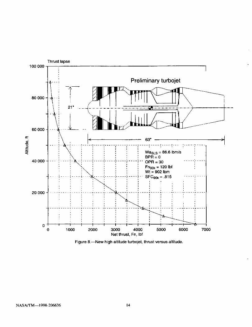
It would be possible to design a new turbojetengine for flying beyond the J97's -80 kft limits usingpresent day materials and turbine technology. Thisengine would incorporate a high pressure ratiocompressor (25 to 35 to 1) with wide chord first stageblades (to minimize Reynolds number effects) and astabilized pilot flame combustor (using a secondaryfuel such as hydrogen) to prevent flameout at highaltitudes. Figure 8 shows the preliminary conceptlayout for such an engine. Compared to the J97, thisnew engine has larger flow areas (larger diameter),more turbo-machinery stages, higher overall pressureratio, higher flameout altitudes, and more thrust. AsFig. 8 shows, this engine would be capable ofaltitudes up to ~90 kft at subsonic speeds. Becausethese adaptations for the >80 kft flight regime make it
larger and heavier than the J97, it would not becompetitive with other jet engines for most missions.
Unfortunately, costs preclude development of anew turbine engine. Compass Arrow's J97, which wasa Cold War scaling/adaptation from the larger GE-1,cost approximately $60M to develop during the mid1960'so This is a sum roughly equal to $300M today.The market anticipated for atmospheric scienceaircraft consists of no more than a dozen units. As a
result, the only turbine engine that would be availablefor a new atmospheric science aircraft would be a J97unit rebuilt from the remaining inventory of prototypehardware that never became a manufacturer
supported product.
NASA/TM--1998-206636 3

PROPULSION SYSTEM SELECTION FORATMOSPHERIC SCIENCE AIRCRAFT
These considerations leave the turbochargedreciprocating engine as the only remaining candidate,since it is the only low cost candidate. The turbo-charged engine is low cost, because of the existingtechnology base of mass produced automotive andgeneral aviation hardware that can be adapted tobuild such an engine. The technology is widely avail-able and well supported. Recent trends in automobilemanufacture to reduce weight (improve fuel economy)have rendered this technology base more applicableto aircraft propulsion, to the extent that many generalaviation home builders have developed automotivepowerplant conversions that are weight competitivewith certified aero engine installations. There is amarketplace for turbocharged engines that alreadyincludes a number of small business developers whomainly modify and assemble hardware manufacturedby others (for auto racing, experimental and homebuiltaircraft etc), some of whom might find a nicheparticipating in the development/manufacture/service/support of specialized turbocharged powerplants forhigh altitude unmanned aircraft (potentially aprofitable niche for commercial HALE platforms, a verysmall niche for atmospheric science aircraft).
The turbocharged powerplant is cheaper becauseit is built up from mass produced components fromother applications which have been adapted. Thedevelopment costs are low because of theconsiderable design heritage that survives from pre-jetage aviation development, and experience gainedfrom earlier attempts to develop turbocharged highaltitude powerplants. Several multiple stageturbocharged systems have already beendemonstrated either in high altitude flight or altitudetest chambers. Table II (previous high altitudeturbocharged IC engines) summarizes the flightcapability/performance that has been achieved todate.
The turbocharged reciprocating engine istechnically quite competitive with the turbine engine athigh altitudes. Although the power density of a turbineengine is higher than the reciprocating engine atnormal altitudes, the reciprocating engine begins tocompare favorably with turbine engine at altitudesabove 80 kft, especially at the lower speeds whereinlet precompression is not available. While it must beaugmented with multiple stages of turbocharging andintercooling for atmosphere pressure/density compen-sation, the reciprocating engine's weight growth withaltitude is not as rapid as the pure turbine engine's;mainly because the turbomachinery needed to raiseOPR is confined to the induction air, which is less than1/10th the overall air consumption.
The highest altitude potential accrues to the sparkignited gasoline engine since it burns a nearlystochiometric fuel air mixture, thus maximizinginduction air utilization. Furthermore, its exhaust gasesare hot enough (1400 to 1600 °F) to yield excessenthalpy which is needed to provide the turbochargercompressor work. Intake pressurization isaccomplished by multiple stage units arranged incascade, so that as altitude increases and ambientpressure decreases, the increasing pressure ratioacross the turbine increases enthalpy extraction,roughly balancing the increased compressor loading.
The power density of the turbochargedreciprocating engine is limited by core enginedetonation limits not the turbomachinery, so theresulting curve of performance with altitude (shown inFig. 9) is _flat" extending from sea level to criticalaltitude where the turbo-machinery was sized (todeliver rated intake airflow and pressure). Abovecritical altitude the turbo-machinery can no longersustain these airflows, so the performance curveexhibits a lapse behavior similar to the turbojet. As adesign parameter, critical altitude shouldapproximately coincide with the aircraft's designaltitude and not exceed it, since the high altitudepower generation capability so dearly paid for inpropulsion weight is wasted beyond that point.
Figure 10 shows specific air consumption of fiveair breathing engine types. Of these, the spark ignitedgasoline engine has the lowest specific air consump-tion. Owing to its near stochiometric combustion, itutilizes all the air which is processedma majoradvantage where air processing makes up most ofthe powerplant. In addition, the turbocharged reci-procating engine retains lower fuel consumption.Table III compares the specific weight and thrustspecific fuel consumption of representative turbojetand turbocharged powerplant installations at 80 and90 kft. Specific weights apply to the entire propulsionunit (including drivetrains, propellers, heat exchangers,etc.) and flight speeds are chosen to provide eachpowerplant with its inherent competitive advantage.Comparison shows that at 80 kft the turbochargedpropeller unit will be slightly heavier per Ibf thrust thanthe turbojet, but it will have lower thrust specific fuelconsumption (TSFC). If the comparsion is repeated at90 kft, the turbocharged unit is somewhat lighter thanthe turbojet per Ibf thrust and has lower TSFC. Thesesame trends were also observed when turbochargedreciprocating engines were compared with specializedturboprop units designed for 90 kft [2].
These performance advantages may be exploitedto a limited extent, but due to the increasing size andweight of ancillaries required to maintain altitudeperformance, the powerplant eventually becomes tooheavy to be supported by the wing loading available.
NASA/TM--1998-206636 4
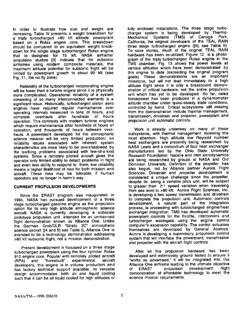
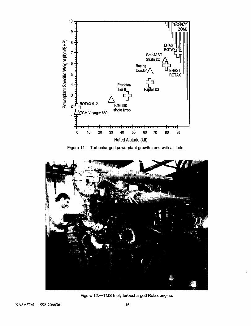
In order to illustrate how size and weight areincreasing, Table IV presents a weight breakdown fora triply turbocharged >80 kft altitude powerplantbased on a Rotax engine core. This breakdownshould be compared to an equivalent weight break-down for the single stage turbocharged Rotax enginethat is designed for 15 kft. NASA airframe/
propulsion studies [3] indicate that for subsonicairframes using modern composite materials, themaximum altitude potential for subsonic flight will belimited by powerplant growth to about 90 kft (seeFig. 11, the no fly zone).
Reliability of the turbocharged reciprocating enginewill be lower than a turbine engine since it is physically
more complicated. Operational reliability of a systemconsisting of so many interconnected elements is asignificant issue. Historically, turbocharged piston aeroengines have required regular maintainance overoperating intervals measured in tens of hours, andcomplete overhauls after hundreds of hoursoperation. This contrasts with modern turbine engineswhich require maintainance after hundreds of hours of
operation, and thousands of hours between over-hauls. A powerplant developed for the atmosphericscience mission will be very limited production; so
reliability issues associated with inherent systemcharacteristics are more likely to be overshadowed bythe teething problems associated with few-of-a-kindsystems. Since a remotely piloted aircraft gives theoperator only limited ability to detect problems in flightand even less ability to respond to them, low reliabilitymeans a higher likelihood of loss for both mission andaircraft. These risks may be tolerable if humanoperators are no longer in harm's way.
CURRENT PROPULSION DEVELOPMENTS
Since the ERAST program was inaugurated in1994, NASA has pursued development of a three
stage turbocharged gasoline engine as the propulsionoption for its very high altitude atmospheric scienceaircraft. NASA is currently developing a subscaleprototype propulsion unit intended for an unmannedflight demonstration known as Alliance One. Unlikethe German Grob/DLR "Strato 2C" atmospheric
science aircraft ([4 and 5] see Table I), Alliance One isintended to be a technology demonstrator addressing>80 kft subsonic flight, not a mission demonstration.
Present development is focussed on a three stageturbocharged powerplant using the four cylinder Rotax912 engine core. Popular with remotely piloted aircraft(RPA) and "homebuilt" experimental aircraftdevelopers, this engine is in volume production andhas factory technical support available. Its versatiledesign accommodates both air and liquid coolingsuch that it can be all liquid cooled for high altitudes or
fully enclosed installations. The three stage turbo-charger system is being developed by Thermo-Mechanical Systems (TMS) of Canoga Park,California, the oi'iginal developers of the TEAL RAINthree stage turbocharged engine ([6], see Table II).To save money, much of the original TEAL RAINhardware has been re-utilized. Figure 12 is a photo-
graph of the triply turbocharged Rotax engine in theTMS chamber, Fig. 13 shows the power levels atvarious altitudes which have been demonstrated by
this engine to date (exceeding the original programgoals). These demonstrations are an importantmilestone, but will not lead immediately to a high
altitude flight since it is only a brassboard demon-stration of critical hardware, not the entire propulsion
unit which has yet to be developed. So far, ratedhorsepower has been produced in a dynamometeraltitude chamber under quasi-steady state conditions,
controlled by hand. Critical subsystems still missingfrom the demonstration include thermal management,transmission, drivetrain and propeller, powerplant and
propulsion unit automatic controls.
Work is already underway on many of these
subsystems, with thermal management receiving themost attention. High altitude low Reynold numberheat exchangers are presently being researched byNASA Lewis and a consortium of four heat exchangermanufacturers led by the Ohio State UniversityResearch Foundation. Nacelle and inlet aerodynamics
are being researched by groups at NASA and OldDominion University. Definition of the propeller hasalso begun, led by Alliance partner Aurora FlightSciences. Drivetrain and propeller development isconsidered a unique challenge since the propeller,despite its being a variable pitch unit, will be subjectto greater than 2:1 speed variation when traversingfrom sea level to >80 kft. Aurora Flight Sciences, Inc.is developing a two speed transmission and drivetrainto complete the propulsion unit. Automatic controlsdevelopment, a natural part of the integrationprocess, is proceeding with turbocharged engine/heatexchanger integration. TMS has developed automaticpowerplant controls for the throttle, intercoolers andturbocharger wastegate using the engine controlcomputer's expansion capability. The control actuatorsthemselves are developed by General Atomics.Aurora is developing a supervisory propulsion control
system that will interface the powerplant, transmissionand propeller with the aircraft flight controls.
After all this propulsion hardware has beendeveloped and extensively ground tested to ensure it'_vorks as advertised," it will be integrated into the
Alliance One airframe leading to the ultimate objectiveof ERAST propulsion development: flightdemonstration of affordable technology to meet the
science mission requirements.
NASA/TM--1998-206636 5
SUMMARY AND CONCLUSIONS REFERENCES
The atmospheric science mission requirementsdictate a very high altitude subsonic aircraft. Thisaircraft requires a propulsion system which presentlydoes not exist, but can be developed from airbreathing engine technology. There are twocandidates: turbojets and propeller/turbochargedspark ignited reciprocating engines. Although theturbojet would appear to be the leading candidate, asit was for high altitude missions historically, there is noturbine engine available for the atmospheric scienceflight regime, and it is unlikely that a suitable turbineengine will ever be developed, due to the limitedmarketplace associated with atmospheric scienceapplications.
Therefore, the propeller/turbocharged spark ignitedgasoline engine is the only option available.Fortunately, the spark ignited powerplant enjoys somesubtle physical advantages over the turbojet for highalitude low speed flight, arising from its near-stochiometric combustion. Its low specific airconsumption reduces the amount and weight ofturbomachinery required to generate power at >80 kft,which apparently results in lower weight and lowerTSFC than a turbojet in this flight regime, despite thelarge heat exchangers.
Borrowing from the technology heritage ofautomotive and homebuilt/experimental aircraftpowerplants and Cold War era high altitude militaryreconaissance development programs, NASA is nowdeveloping a variant of the 3 stage turbochargedpowerplant for application to the atmospheric sciencemission. To date, only the engine and turbochargerperformance has been demonstrated, under carefullycontrolled conditions. Work is ongoing to develop theremaining required components, and build thedemonstration hardware into a propulsion systemwhich will lead to an aircraft technology flight feasibilitydemonstration.
1. W. Wagner and W. Sloan, "Fireflies and Other
UAV's," Teledyne Ryan Aeronautical Co.,San Diego CA, June 1993.
2. J.L.Bettner, C.S. Blandford and B.J. Rezy,"Propulsion Assessment for Very High AltitudeUAV Under ERAST," NASA Report 95N27866,Allison Engine Company, June 1995.
3. Report of the Environmental Research Aircraft and
Sensor Technology (ERAST) Program Leader-ship Team, "A Review of Remotely PilotedAircraft (RPA) Technology Required for HighAltitude Civil Science Missions," NationalAeronautics and Space Administration,Washington DC, March 1996.
4. H. Tonksotter, "The Strato 2C Propulsion System;A Low Cost Approach for a High Altitude LongEndurance Aircraft," Industrieanlagen-Betriebsgesellschaft mbH, March 1994.
5. Anon, "Strato 2C Technical Description", DeutscheForschungsanstalt fur Luft und Raumfarht (DLR) ,November 1993.
6. J. Harp, "Turbocharger System Development andPropulsion System Testing:, TMS Report No.SR-36, prepared for Developmental SciencesInc. under Contract No. DSI-80-TR-SC-05oA,
ThermoMechanical Systems Inc., Canoga ParkCA, May 1982 (declassified Mar 1994).
NASA/TM-- ! 998-206636 6

Aircraft designation
WB-57
ER-2
AQM91M
Compass Arrow
Grob Egrett
Boeing Condor
Grob Strato 2C
TABLE I.--PREVIOUS HIGH ALTITUDE SUBSONIC AIRCRAFT
Original purpose, and
year flown
High altitude strategic
bomber (19491
High altitude
reconnaissance (1955 I
High altitude
reconnaissance 119691
High altitude science
aircraft (1988 t
High altitude ELINT
reconnaissance (1989 /
Atmospheric science(1995)
Altitude
record
65,876 ft8/29/55
73,200 ft8/4/95
>81,000 ft
Sept. 196953,055 ft
9/1/88
67,028 ft2/15/89
60,867 ft6/4/95
Propulsion systemused
Bristol
"Olympus" turboietGE-F118
turbofan
GE-J97-3
turbojetGarrett TPE331
turboprop
2 stage turbocharged
spark i_lnition engine
3 stage turbocharged
spark ignition engine
Science platform
availability
NCAR atmosphericscience
NASA atmosphericscience
military only, no
longer existsDoE atmospheric
science
military only, no
IOn_ler existsDLR (Germany)
program wascanceled
TABLE II.--TURBOCHARGED RECIPROCATING ENGINES
TEAL RAIN
Condor
Strato 2C
Raptor D2
Perseus B/Theseus
Altus
ERAST Alliance I
Proof of Concept
(P.O.C)
Developer
Thermo
Mechanical
Systems
{TMS)
Boeing
TeledyneContinential
Motors
Grob/IABG/
DLR
Scaled
Composites/TMS
Aurora FlightSciences
General
Atomics
AeroSystems/TMS
Thermo
Mechanical
Systems
(TMS)
Core engineused
3 cylinderDrake 36.6 cid
6 cylinderContinental
350 cid
6 cylinderContinential
550 cid
4 cylinderROTAX 74 cid
4 cylinderROTAX 74 cid
4 cylinderROTAX 74 cid
4 cylinderROTAX 74 cid
Number of
stages/turbomanufactor
3 stages/I'MS
2 stages/
Teledynecontinental
3 stages/IABG/P+W/
Garrett
2 stages/TMS
3 stages/Garrett
2 stages/TMS
3 stages/TMS
Rated hp demoat rated alt.
70 hpat 65 kft
Feb. 1982
182 hpat 67kft
Feb. 1989
400 hpat78kft
Dec. 1994
103 hpm54kft
Jan. 1996
73 hpat 59kft
May 1994
103 hpat54kft
Jan. 1996
100 hpat76 kft
Feb. 1997
Highest recorded
ground test
performance
47 hpat90kft
Mar. 1982
data not
available
308 hpat 82 kft
Apr. 1995
47 hpat 70kft
Jan. 1996
73 hpat 59kft
May 1994
47 hpat 70kft
Jan. 1996
85 hp85kft
Nov. 1997
Highest altitude
achieved in flight
ground demo
only
67,028 ftFeb. 1989
60,876 ft
Aug. 1995
Not flown yet
20,000 ft
Mar. 1996
Not flown yet
Not flown yet
NASA/TM--1998-206636 7
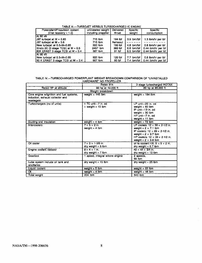
TABLE III.--TURBOJET VERSUS TURBOCHARGED IC ENGINE
Powerplant/Propulsion system
linlet recovery = 1.0 IAt 8O kft
J97 turbojet at M = 0.83
J97 turbojet at M = 0.8New turbojet at 0.5<M<0.85
Strato 2C (3 stage TCSI) at M = 0.5
80K ERAST 3 stage TCSI at M = 0.4At90 kft
New turbojet at 0.5<M<0.85
90 K ERAST 3 stage TCSI at M = 0.4
Uninstalled weight
including propeller
715 Ibm
715 Ibm
920 Ibm
2457 Ibm
587 Ibm
920 Ibm
667 Ibm
Delivered
thrust
184 Ibf
flameout
190 Ibf
360 Ibf
91 Ibf
120 Ibf
90 Ibf
Specific
wei_lht
3.9 Ibm/lbf
4.8 Ibm/Ibf
6.8 Ibm/Ibf
6.5 Ibm/Ibf
7.7 Ibm/Ibf
7.4 Ibm/Ibf
Specific
consumption
1.3 Ibm/hr per Ibf
0.8 Ibm/hr per Ibf
0.44 Ibm/hr per Ibf
0.44 Ibm/hr per Ibf
0.8 Ibm/hr per Ibf
0.44 Ibm/hr per Ibf
TABLE IV.--TURBOCHARGED POWERPLANT WEIGHT BREAKDOWN COMPARISON OF "UNINSTALLED
HARDWARE" NO PROPELLER
Rotax 914
Rated HP at altitude 80 hp at 12,000 ft
Core engine w/ignition and fuel systems,induction, exhaust collector and
waste_late
Turbochargers (no of units)
Ductin_l and insulationIntercoolers
Oil cooler
Engine coolant radiator
Gearbox
Weicjht breakdown
weight = 145 Ibm
1 TC unit--7 in. od
x weight = 15 Ibm
weight = 4 Ibm7×5×2in.
weight = 4 Ibm
7x3x 1-3/8in.
dry weight = 5 Ibm8×4×1in.
dry weight = 7 Ibm
1 speed, integral w/core engine
Lube system include oil tank and dry weight = 15 Ibmancillaries
Liquid coolant weicjht = 5 Ibm£_1
Total weight
weight = 4 Ibm204 Ibm
3 sta_le turbochar_led ROTAX
80 hp at 85,000 ft
weight = 184 Ibm
LP unit--20 in. od
weight = 60 IbmIP unit--13 in. od
weight = 30 IbmHP unit--7 in. od
weight = 11 Ibm
weight = 72 IbmLP coolers: 12 × 56 x 2-1/2 in.
weight = 2 x 7.1 IbmIP coolers: 12 x 69 x 2-1/2 in.
weight = 2 x 9.7 IbmHP coolers: 12 x 39 × 2-1/2 in.
wei_lht = 2 x 5.8 Ibmoil to coolant HX: 9 x 9 x 2 in.
dry wei_lht = 6.7 Ibm42x 44x 3/4 in.
dr_ weight = 13 Ibm
2 speeds,55 Ibm
dry weight = 25 Ibm
weight = 22 Ibm
weicjht = 18 Ibm543 Ibm
NASAFFM--1998-206636 8
1.0 -_100
0.8 80o 0
0.7 _ 70 do6 6o_-
--_ 0.5 _ Recovery // 1 50 "_
._o.3 " o "" __°o_0.1 10 o
0.0 , 00 I0 20 30 40 50 60 70 80 90
Altitude, ft. x 10-3
Figure 1.--Pressure ratio needed for flat-rated output power and relativewing lift versus altitude for constant flight Mach number of 0.50.
NASA/TM--1998-206636 9
Sizing for altitude compensation (constant mass flow rate)
Axial Compressor10 - 100 Ibm/sec
(pressurizes combustor to 40 psia)
DiameterDAc__ ._ ....................
v ....
'/ Length LAC -
Centrifugal Compressor0.1 - 0.5 Ibm/sec
(pressurizes engine intake
manifold to 30 in Hga)
• D
DiameterDcc [_ [_ [_
Length
LAC
(/)a)-a_7-
-E
5--t,/)
o
._ 4-
¢n 3--¢-o
¢-
2--E_5
__
LAC DAC,DCC
LCC
Stages
2 Stages
1 StageI i _ I I I ' ' I ' ' ' I _ _ i I _ _ _ I
0 10 20 30 40 50 60 70 80 90 100
Inlet altitude (kft)
Figure 2.--Turbocompressor size variation with altitude.
NASA/TM--1998-206636 10
_,- q.)Q) ""z
4-o>,,,o,
--rOt)
,,_E-o0 Q_
"-' N
._gE-.J 0
Z
-O- FrontalAreaDryWeightWetWeight
0 10 20 30 40 50 60 70 80
Altitude (kft)
Figure 3.--Heat exchanger size variation with altitude.
90 100
%
100,000
80,000
60,000
40,000
20,000
0
0.01
I
0.1
M=0.8 M=0.4
l"lp =`5.6.7.8.9 rip =.5.6.7.8.9.95.98
...... ....
i i l i l ii I l i l II III I I I I Ilia| I I I IIIII i I I I I Ill
0.1Ca
I I i I I
10
_ture Area, ft2| | |
Diameter, ft
100
I I I I I I I
10
1000
Figure 4.--Approximate capture area and diameter required for 100 Ibfthrust versus altitude, airspeed and desired propulsive efficiency.
NASA/TM--1998-206636 11
(- _ --Low Pressure-----
"_C__mp ressor Turbiner._,_'[_
Am_l LPC _ ,_ ,_,- __pT I Exh"aus.._._.__t
I _ I --High Pressure-- I _ _l/''-'l
II .r_. °mpress°r Turbin_I I "_ Nozzle
_1Co_ustor_Figure 5.--High altitude turbojet.
>
Trans-
mission
Fourcylinder
coreengine
Ambient air_
Inlet/diffuser
r_ Wastegate
Variable area nozzle
(v.a.n.)
•r,,\Ambient air ..,,
Inlet/diffuser
I_-_ IP turbo
. 1/ charger
Ambient air_ L'_ LP inter _
c----_ I coolerI_,)
charger Fixed nozzle
Inlet/diffuser
Figure 6.nThree Stage Turbocharged Powerplant.
Oil andcoolant
heat loads
Ambient air
V
Inlet/diffuser
Enginecoolantradiator
Variable
areanozzle
(v.a.n.)
NASA/TM-- 1998-206636 12
90 000
80 000
70 000
60 000
-50 000
40 000
30 000
20 000
10 000
Classified
Performance Size
WasLs = 66.2 Ibm/s
OPRsLs = 11.5
FnM = .83at 80k = 184 Ibf
SFCM = .83 at 80k = 1.298
Lengthbare = 110 in.
Weightdry = 694 IbI
(Maximum available thrust)
0 1000 2000 3000 4000 5000Fn, Ibs
Figure 7.--"Compass arrow" high altitude turbojet (1966-72), thrust versus altitude.
NASA/TM--1998-206636 13
-o
100 000
80 000
60 000
40 000
20 000
0
Thrustlapse
i II
I
--i Preliminary turbojeti
,, _,, // I I .' _ " ' ''_ \ I, 21 ....__......._ .........,,......? t....
.......... :..........L......'__.___;;.......;............. -_
.............................
i ! ',_ i i i i i Fn90k = 120 Ibf i
! : ',I _ .i " ', ', ', Wt = 902 Ibm ',
0 1000 2000 3000 4000 5000 6000 7000
Net thrust, Fn, Ibf
Figure 8.--New high altitude turbojet, thrust versus altitude.
NASA/TM--1998-206636 14

gI 9£990_-866I--IAHJVSVN
•ez!s/ueu!qoeLuocpnl selelo!puo!_dLunsuo0J!eo!I!oeds--'OkeJnS!-I
t_'O=_ tr'O=_ tr'O-_ S'O=_'JelledoJd ',elledoJd 'JelledoJd 'doJduoJ.s!dOl _eloJOl lese!pOl oqJnl
•_aq'dH aedtuql
JqlJedJqJeduJqli
(0'I.=/tle^ooeJlelu!'L:I_= o.tleJeJnsseJde6elsOd'l)
IPlOg @ dHOOL ao_MOlp!eoes/tuqlisefu!olpeJ!nbeJez!.slaetlMOd'l
8'0=_1el
oc Jnl
OL --=
"0
-0_
•eoueLuJojJed eu!6ue pe6JeqooqJnl--'6 eJn6!=l
(_) epnJ,o,IV
O0 I. 06 Og OL 09 Og O_ 0£ Oa 0 L '3"S
......... I ......... I ......... I ......... t ......... I ......... t ......... I ......... t ......... I .........
', ; : :......... - ................. - .......................... ,,........ _........ ,........ r .....
........i........:I................::........i....................................
........ ,_................. _,............... _,........ ,........ - ........ , ........ - ........
, .i........ -'...... ',........ " ........ '......... " ................. ÷........
'* : i ' : ' : ', , _ : , : ,
, : , , , , , , :' i , t t , ..
...... _ ...... J ........ T ........ I ........ T ........ _ ........ T ........ I ........ T ......
, , , : , : , ,: - ,_............. ,_................. ,_................. ,_................. - ........, ', , ', , , , , , ,
:........ .:........ :.. i , , i
0
OL
OE
0£
O_
os
09
OL
Oe
06
OOL
10
._o 5-
_" 4-
t--m
_. 3-
O..
I
/XROTAX912"1_TCMVoyager550
"Ill'__'_zo.E
' llllERAS]
ROTA)_Grob/IABG rdl III
Strato2C _k_ "llllllBoeing L _1 --IIIIco.do;/k UE.A;TIIII
re°.or, O' '11TierII RaptorD2 I
© ITCM550singleturbo
....I....I....I....I....I....I....I....I....I0 10 20 30 40 50 60 70 80 90
RatedAltitude (kft)
Figure 11.--Turbocharged powerplant growth trend with altitude.
NASA/TM--1998-206636
Figure 12.--TMS triply turbocharged Rotax engine.
16

$oQ.
o¢-
.i,..,G)EoE
t-
O
110--
IO0 --
90--
80--
70--
60--
50--
40--
30--
20--
10--
O--
run #28602/18/97 run #290
02/18/97run #276 run #278 run #281 run #28402/18/97 0_18/97 02/18/97 02/18/97 /
#294run[] N[] oo ooo OoOoOoOoOoOo[] ooooooo [] [] u°o o o o o o o o o o o o o " 02/18/97
000000000000000000000000 _ 00 O0000000OO00OOOOOOO00000000OO0000
0000000000000000000000000000000000000000000000000000000000000000ooo oooo o oo o oo o o o ooo oo o ooooo ooo oo _run#570ooooooooooooooooooooooooooooooo Uooo o ooo o oo o oo oo o ooo oo o oo o o o oo oo o 07/03/97000000000000000000000000000000000
000000000000000000000000000000000000000000000000000000000000000000
00000000000000000000000000000000000000000000000000000000000000000000
0000000000000000000000000000000000o o o o o o o o o o o o o o o o o o o o o o o o o o o o o o o o o _ run#574ooooooooooooooooooooooooooooooooo i l
o o o o o o o o o o o o o o o o o o o o o o o o o o o o o o o o o _ nTl_IQ700000000000000000000000000000000000 v'/vv'_"
0OOOOOOOOO^^_^^^^^_^^^0OO0000000000
o o o o o o o o o o ° v_.,_Nneratinn _ v,rPnv_lone' ° o o o o o o o o o o o o0000000000 0000000000000OOOOOOOOOOO _0OOOOOOOOOOOO
0000000000000000000000000000000000000000000000000000000000000000000000000
000000000000000000000000000000000000OOOOOOOOOOOOOO OOO000OO OO
o o o o o run #152 run #157o o o o run #150 o run #154 run #502
ooo _/o OoOoo 11/20/96 11/20/96 11/ /96 06/19/97[]°°°°%°0°° [] [] [] [] 11/20/96 [] _ [] [] 0%
o o o o o o run#153 [] run #155 o run #41800 0 0
o o o o o o o run#151 11/20/96 11/20/96 oOoO_oOo 05/13/97000000000 000 00o o o o o o o o o 11120196 o o o o o o o o o o o0000000000
0000000000000000000000000000000000000000000000000000000000000000000000000000000
OOOOOOOOOOOOOOOOOOOO000000OOOOOOOOOOOOOO0000000000000000000000000000000000000000
000000000000000000000000000000000000000000000000000000000000000000000000000000000
0000000000000000000000000000000000000000000000000000000000000000000000000000000000
00000000000000000000000000000000000000000
000000000000000000000000000000000000000000000000000000000000000000000000000000000000
000000000000000000000000000000000000000000000000000000000000000000000000000000000000
0000000000000000000000000000000000000000000000000000000000000000000000000000000000000
0000000000000000000000000000000000000000000OOOOOOOOOOOO 0000000000000000000 OOO000
OOOOOOO00000 _OOOOOOOOOOOOOOOOOO _ OO
000000000000_ 0 000000_ 000 _ []
o o o o o o o o o o o o []o o o o o o U run #579 run #57700000000000000 0 0 0 0 0 000
0 0 0 00 0000000000000 00
00 0 0 0 0 000O O O O O O O O O
O 0 O O O O O O000 O O O 00
O O 00 O O O0 O O 0 O O O
O 0 O O O O000 0 O O
O O O O 0O O O 0 O
0000O O O O
O 00O O O
00
r-1 °
run #581 run #580 07/03/97 07/03/9707103/97 07/03/97
I....I....I....'....I....i....I....'....I....i....I....'....I....'....I....t....I....'....I....'....I....'S.L. 10 20 30 40 50 60 70 80 90 1O0
Chamber altitude (kft)
Figure 13.--TMS three stage turbocharged engine performance demonstration.
NASA/TM--1998-206636 17
REPORT DOCUMENTATION PAGE Form ApprovedOMBNO.0704-0188
Public reporting burden for this collection of information is estimated to average 1 hour per response, including the time for reviewing instructions, searching existing data sources,gathering and maintaining the data needed, and completing and reviewing the collection of information. Send comments regarding this burden estimate or any other sspecl of thiscollection of information, including suggestions for reducing this burden, to Washington Headquarlers Services, Directorate for Information Operations end Reports, 1215 JeffersonDavis Highway, Suite 1204, Adington, VA 22202-4302, and to the Office of Management and Budget, Paperwork Reduction Project (0704-0188), Washington, DC 20503.
1. AGENCY USE ONLY (Leave blank) 2. REPORT DATE 3. REPORT TYPE AND DATES COVERED
April 1998 Technical Memorandum
4. TITLE AND SUBTITLE
Propulsion System for Very High Altitude Subsonic Unmanner Aircraft
6. AUTHOR(S)
David J. Bents, Ted Mockler, Jaime Maldonado, James L. Harp, Jr.,
Joseph F. King, and Paul C. Schmitz
7. PERFORMING ORGANIZATION NAME(S) AND ADDRESS(ES)
National Aeronautics and Space Administration
Lewis Research Center
Cleveland, Ohio 44135-3191
9. SPONSORING/MONITORING AGENCY NAME(S) AND ADDRESS(ES)
National Aeronautics and Space Administration
Washington, DC 20546-0001
5. FUNDING NUMBERS
WU-529-10-13-00
8. PERFORMING ORGANIZATION
REPORTNUMBER
E-11101
10. SPONSORING/MONITORING
AGENCY REPORT NUMBER
NASA TM--1998-206636
11. SUPPLEMENTARY NOTES
Prepared for the Aerospace Power Systems '98 sponsored by the Society of Automotive Engines, Williamsburg, Virginia,
April 21-23, 1998. David J. Bents, Ted Mockler, and Jaime Maldonado, NASA Lewis Research Center; James L. Harp, Jr.
and Joseph E King, ThermoMechanical Systems Inc., Canoga Park, California; Paul C. Schmitz, Power Computing
Solutions Inc., Avon, Ohio. Responsible person, David J. Bents, organization code 5440, (216) 433-6135.
12a. DISTRIBUTION/AVAILABILITY STATEMENT
Unclassified - Unlimited
Subject Category: 07 Distribution: Nonstandard
This publication is available from the NASA Center for AeroSpace Information, (301 ) 621-0390.
12b. DISTRIBUTION CODE
13. ABSTRACT (Maximum 200 words)
This paper explains why a spark ignited gasoline engine, intake pressurized with three cascaded stages of turbocharging,
was selected to power NASA's contemplated next generation of high altitude atmospheric science aircraft. Beginning
with the most urgent science needs (the atmospheric sampling mission) and tracing through the mission requirements
which dictate the unique flight regime in which this aircraft has to operate (subsonic flight @ >80 kft ) we briefly explore
the physical problems and constraints, the available technology options and the cost drivers associated with developing a
viable propulsion system for this highly specialized aircraft. The paper presents the two available options (the turbojet
and the turbocharged spark ignited engine) which are discussed and compared in the context of the flight regime. We
then show how the unique nature of the sampling mission, coupled with the economic considerations pursuant to aero
engine development, point to the spark ignited engine as the only cost effective solution available. Surprisingly, this
solution compares favorably with the turbojet in the flight regime of interest. Finally, some remarks are made about
NASA's present state of development, and future plans to flight demonstrate the three stage turbocharged powerplant.
14. SUBJECT TERMS
High altitude; Air breathing propulsion; Turbine engines; Reciprocating engines
17. SECURITY CLASSIFICATION
OF REPORT
Unclassified
NSN 7540-01-280-5500
18. SECURITY CLASSIFICATION
OF THIS PAGE
Unclassified
19. SECURITY CLASSIFICATION
OF ABSTRACT
Unclassified
15. NUMBER OF PAGES
2316. PRICE CODE
A03
20. LIMITATION OF ABSTRACT
Standard Form 298 (Rev. 2-89)
Prescribed by ANSI Std. Z39-18298 - 102