PROPOSED INSTALLATION OF ELECTRICAL …€¦ · FINAL SCOPING REPORT JULY 2006 ... The project...
59
PROPOSED INSTALLATION OF ELECTRICAL INFRASTRUCTURE IN THE COEGA IDZ ENVIRONMENTAL IMPACT ASSESSMENT EIA/12/12/20/781 FINAL SCOPING REPORT JULY 2006 Prepared for: ESKOM TRANSMISSION PO Box 1091 Johannesburg 2000 Eyethu Engineers CC PO Box 100418 Scottsville Pietermaritzburg 3209 Tel. (033) 342-6891 Fax. (033) 394-9926
Transcript of PROPOSED INSTALLATION OF ELECTRICAL …€¦ · FINAL SCOPING REPORT JULY 2006 ... The project...
PROPOSED INSTALLATION OF ELECTRICAL
INFRASTRUCTURE IN THE COEGA IDZ
ENVIRONMENTAL IMPACT ASSESSMENT EIA/12/12/20/781
FINAL SCOPING REPORT
JULY 2006
Prepared for:
ESKOM TRANSMISSION PO Box 1091 Johannesburg 2000
Eyethu Engineers CC PO Box 100418 Scottsville Pietermaritzburg 3209 Tel. (033) 342-6891 Fax. (033) 394-9926
EYETHU ENGINEERS cc JULY 2006 COEGA ELECTRICAL INFRASTRUCTURE EIA - FINAL SCOPING REPORT 1
EXECUTIVE SUMMARY.......................................................................................... 5
CHAPTER 1 THE EIA PROCESS FOLLOWED FOR THE PROJECT............................. 6
1.1 BRIEF BACKGROUND TO THE PROJECT ............................................................. 6
1.2 THE EIA PROCESS FOLLOWED ............................................................................ 9
1.3 SCOPING ............................................................................................................ 11 1.3.1 Authority Consultation........................................................................................ 12 1.3.2 Specialist Input.................................................................................................. 12 1.3.3 Site Visit............................................................................................................ 13 1.3.4 Information Gathering ....................................................................................... 13
1.4 PUBLIC PARTICIPATION ................................................................................... 13
1.5 CONTENTS OF FINAL SCOPING REPORT.......................................................... 14
CHAPTER 2 THE LEGAL POSITION ....................................................................... 15
2.1 INTRODUCTION ................................................................................................. 15
2.2 PERTINENT ENVIRONMENTAL LEGISLATION.................................................. 15
2.3 SPECIFIC RELEVANT ENVIRONMENTAL LEGISLATION................................... 17 2.3.1 Environment Conservation Act No 73 of 1989 (ECA) ............................................ 17 2.3.2 National Environmental Management Act No 107 of 1998 (NEMA) ........................ 17
2.4 THE REGULATORY FRAMEWORK ........................................................................ 18 2.4.1 The Electricity Act No. 41 of 1987 (and Electricity Amendment Acts of 1994 & 1995) 18 2.4.2 The Eskom Conversion Act No. 13 of 2001 .......................................................... 19 2.4.3 The Eskom Act 40 of 1987 as amended by the Eskom Amendment Act 51 ............ 19 2.4.4 The White Paper on the Energy Policy of the Republic of South Africa (1998)........ 20
2.5 SUMMARY........................................................................................................... 21
CHAPTER 3 THE NEED FOR THE INSTALLATION OF BULK ELECTRICAL INFRASTRUCTURE IN THE COEGA IDZ ................................................................ 22
3.1 INTRODUCTION ................................................................................................. 22
CHAPTER 4 DESCRIPTION OF THE ENVIRONMENT............................................... 24
4.1 BIOPHYSICAL CHARACTERISTICS ................................................................... 24 4.1.1 Climate ............................................................................................................. 24 4.1.2 Hydrology ......................................................................................................... 25 4.1.3 Geology and soils .............................................................................................. 26 4.1.5 Vegetation ........................................................................................................ 26
EYETHU ENGINEERS cc JULY 2006 COEGA ELECTRICAL INFRASTRUCTURE EIA - FINAL SCOPING REPORT 2
4.1.6 Open space areas .............................................................................................. 29 4.1.7 Fauna ............................................................................................................... 29 4.1.8 Avi-Fauna.......................................................................................................... 29
4.1 SOCIAL AND SOCIO-ECONOMIC CHARACTERISTICS...................................... 31 4.1.1 Institutional Context .......................................................................................... 31 4.1.2 Regional context................................................................................................ 31 4.1.3 Demographic information for the remaining area within the Coega IDZ................. 31 4.1.4 Infrastructure .................................................................................................... 32 4.1.5 Archaeological and cultural resources ................................................................. 33 4.1.6 Visual Receiving Environment ............................................................................. 33
CHAPTER 5: DESCRIPTION OF THE PROPOSED PROJECT ..................................... 34
5.1 PROJECT BACKGROUND .................................................................................... 34
5.2 PRE-CONSTRUCTION ACTIVITIES.................................................................... 39
5.3 CONSTRUCTION, OPERATION AND DECOMMISSIONING ACTIVITIES.......... 39 5.4.1 Work on Substations.......................................................................................... 40
5.4.1.1 Grassridge Substation ................................................................................ 40 5.4.2 Access negotiations ........................................................................................... 44 5.4.2 Tower pegging .................................................................................................. 44 5.4.3 Gate installation ................................................................................................ 44 5.4.4 Excavation of foundation.................................................................................... 44 5.4.5 Foundation reinforcing steelwork ........................................................................ 44 5.4.6 Concrete filling/foundation pouring ..................................................................... 45 5.4.7 Delivery of steel to tower site ............................................................................. 45 5.4.8 Assembly team/punch and paint......................................................................... 45 5.4.9 Erection of towers ............................................................................................. 46 5.4.10 Stringing, sag and tension.............................................................................. 46 5.4.11 Rehabilitation ................................................................................................ 46
5.5 INACCESSIBLE OR SENSITIVE AREAS.............................................................. 46
5.6 OPERATION AND MAINTENANCE ..................................................................... 47
5.7 DECOMMISSIONING.......................................................................................... 47
5.8 DESIGN LIMITATIONS AND PHYSICAL PARAMETERS REQUIRED ................. 47
CHAPTER 7: PROJECT ALTERNATIVES ................................................................. 49
7.1 INTRODUCTION ................................................................................................. 49
7.2 STRATEGIC ALTERNATIVES TO THE INSTALLATION OF BULK ELECTRICAL INFRASTRUCTURE WITHIN THE COEGA IDZ ............................................................... 49
7.2.1 The “Do Nothing” Option.................................................................................... 49 7.2.2 Demand-side Management................................................................................. 49
7.3 DESIGN ALTERNATIVES .................................................................................... 50
EYETHU ENGINEERS cc JULY 2006 COEGA ELECTRICAL INFRASTRUCTURE EIA - FINAL SCOPING REPORT 3
7.3.1 Placing the Transmission Line Underground ........................................................ 50 7.3.2 Alternative Pylon Options ................................................................................... 50 7.3.3 Substation Design Alternatives ........................................................................... 50
CHAPTER 8 IDENTIFICATION OF POTENTIAL ISSUES AND IMPACTS ................... 51
CHAPTER 9 CONCLUSIONS AND RECOMMENDATIONS ..................................... 57 APPENDICES APPENDIX A – ATTENDANCE REGISTERS & MINUTES OF KEY STAKEHOLDER WORKSHOP APPENDIX B – PUBLIC PARTICIPATION REPORT APPENDIX C – ISSUES REPORT (COMMENTS AND RESPONSE) APPENDIX D – GEOTECHNICAL SPECIALIST STUDY APPENDIX E – ECOLOGICAL SPECIALIST STUDY APPENDIX F – AVIFAUNAL SPECIALIST STUDY APPENDIX G– CULTURAL HERITAGE SPECIALIST STUDY APPENDIX H – ESKOM GENERIC EMP FOR LINE CONSTRUCTION APPENDIX I - ESKOM GENERIC EMP FOR SUBSTATION CONSTRUCTION FIGURES FIGURE 1 LOCALITY MAP FIGURE 2: STUDY AREA FIGURE 3: THE EIA PROCESS FIGURE 4: OVERVIEW OF THE ELECTRICITY NETWORK FIGURE 5: PLANNED OPEN SPACE SYSTEM WITHIN THE COEGA IDZ FIGURE 6: AERIAL PHOTOGRAPH SHOWING PROPOSED POWERLINE CORRIDORS FIGURE 7: DIAGRAMMATIC REPRESENTATION OF POWER LINE CORRIDORS IN THE IDZ FIGURE 8: ALTERNATIVE TOWER TYPES FIGURE 9: STRAIN / BEND TOWER TABLES TABLE 1: APPROACH TO THE STUDY TABLE 2: PERTINENT ENVIRONMENTAL LEGISLATION APPLICABLE TO THE PROJECT TABLE 3: IMPACT CRITERIA TABLE 4: POTENTIAL ISSUES AND IMPACTS AND SUGGESTED MITIGATION
EYETHU ENGINEERS cc JULY 2006 COEGA ELECTRICAL INFRASTRUCTURE EIA - FINAL SCOPING REPORT 4
PHOTOS PHOTO 1 : LOCALITY MAP PHOTO 2 : STUDY AREA PHOTO 3 : EXAMPLE OF EIA PROCESS PHOTOS 4 & 5 : TRANSFORMER INSTALLATION PHOTO 6 : EXAMPLE OF TUBULAR ALUMINIUM CONDUCTOR
ARRANGEMENT PHOTOS 7 & 8 : PYLON FOUNDATION (STRAIN / BEND TYPE TOWER) AND PYLON
FOUNDATION STRUCTURES PHOTO 9 : LIFTING OF STRUCTURES FOR LATTICE – TYPE TRANSMISSION LINE
TOWERS ACRONYMS DEAET EASTERN CAPE DEPARTMENT OF ECONOMIC AFFAIRS, ENVIRONMENT AND
TOURISM DEAT NATIONAL DEPARTMENT OF ENVIRONMENTAL AFFAIRS & TOURISM DSM DEMAND SIDE MANAGEMENT DSR FINAL SCOPING REPORT EIA ENVIRONMENTAL IMPACT ASSESSMENT EMP ENVIRONMENTAL MANAGEMENT PLAN IEM INTEGRATED ENVIRONMENTAL MANAGEMENT IAP’S INTERESTED AND AFFECTED PARTIES NEMA NATIONAL ENVIRONMENTAL MANAGEMENT ACT PPP PUBLIC PARTICIPATION PROCESS ROD RECORD OF DECISION IDZ INDUSTRIAL DEVELOPMENT ZONE
EYETHU ENGINEERS cc JULY 2006 COEGA ELECTRICAL INFRASTRUCTURE EIA - FINAL SCOPING REPORT 5
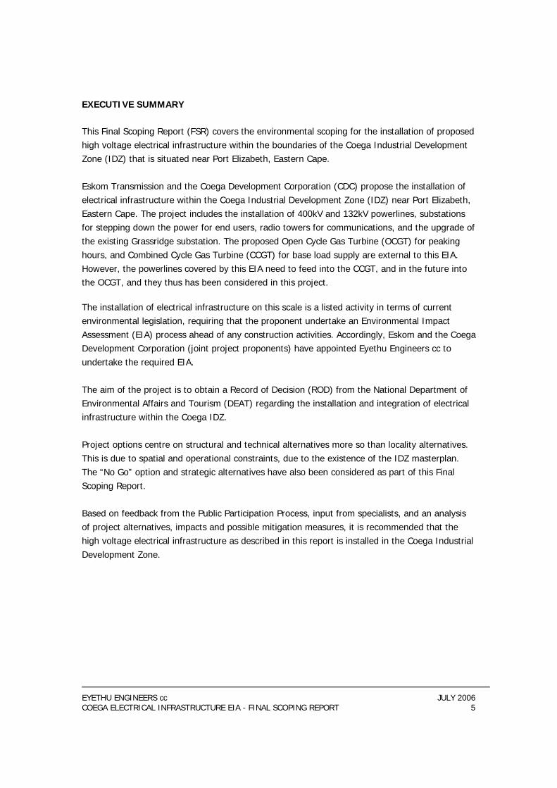
EXECUTIVE SUMMARY This Final Scoping Report (FSR) covers the environmental scoping for the installation of proposed high voltage electrical infrastructure within the boundaries of the Coega Industrial Development Zone (IDZ) that is situated near Port Elizabeth, Eastern Cape. Eskom Transmission and the Coega Development Corporation (CDC) propose the installation of electrical infrastructure within the Coega Industrial Development Zone (IDZ) near Port Elizabeth, Eastern Cape. The project includes the installation of 400kV and 132kV powerlines, substations for stepping down the power for end users, radio towers for communications, and the upgrade of the existing Grassridge substation. The proposed Open Cycle Gas Turbine (OCGT) for peaking hours, and Combined Cycle Gas Turbine (CCGT) for base load supply are external to this EIA. However, the powerlines covered by this EIA need to feed into the CCGT, and in the future into the OCGT, and they thus has been considered in this project. The installation of electrical infrastructure on this scale is a listed activity in terms of current environmental legislation, requiring that the proponent undertake an Environmental Impact Assessment (EIA) process ahead of any construction activities. Accordingly, Eskom and the Coega Development Corporation (joint project proponents) have appointed Eyethu Engineers cc to undertake the required EIA. The aim of the project is to obtain a Record of Decision (ROD) from the National Department of Environmental Affairs and Tourism (DEAT) regarding the installation and integration of electrical infrastructure within the Coega IDZ. Project options centre on structural and technical alternatives more so than locality alternatives. This is due to spatial and operational constraints, due to the existence of the IDZ masterplan. The “No Go” option and strategic alternatives have also been considered as part of this Final Scoping Report. Based on feedback from the Public Participation Process, input from specialists, and an analysis of project alternatives, impacts and possible mitigation measures, it is recommended that the high voltage electrical infrastructure as described in this report is installed in the Coega Industrial Development Zone.
EYETHU ENGINEERS cc JULY 2006 COEGA ELECTRICAL INFRASTRUCTURE EIA - FINAL SCOPING REPORT 6
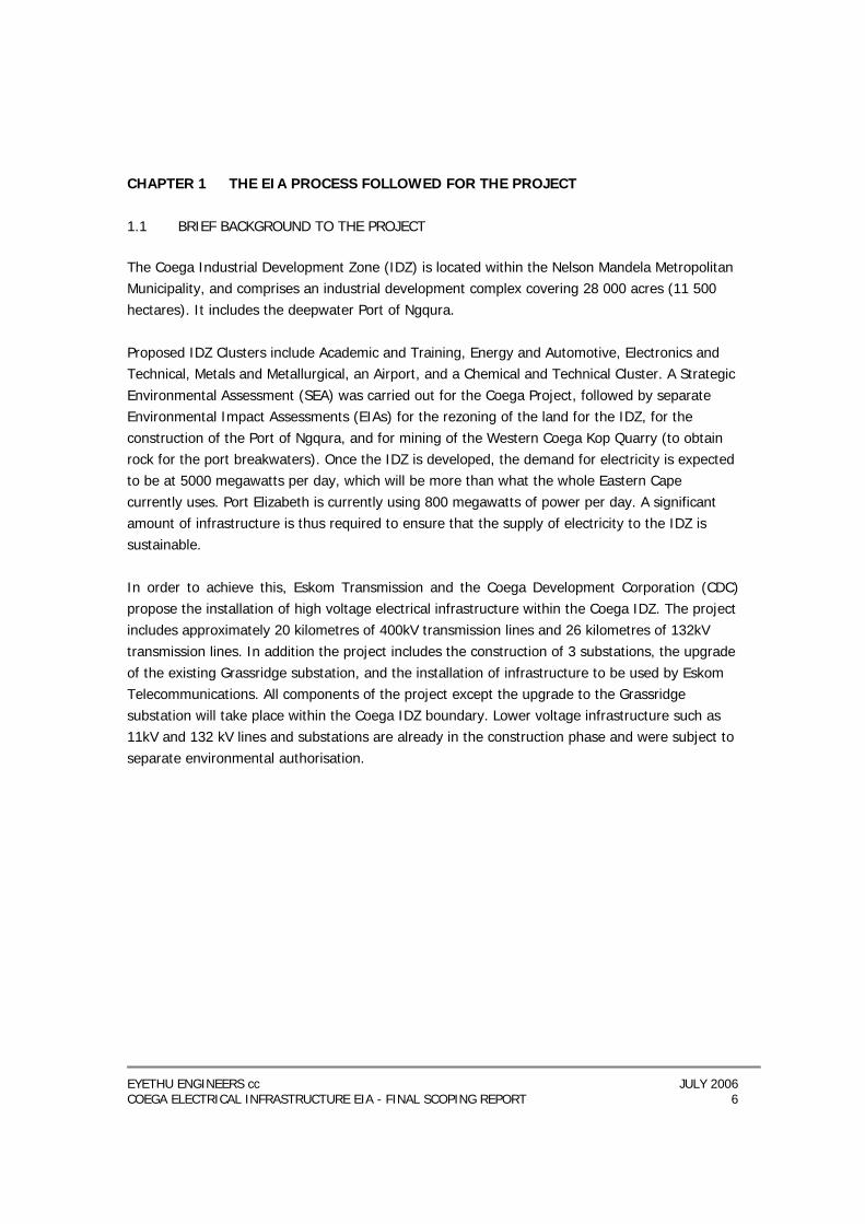
CHAPTER 1 THE EIA PROCESS FOLLOWED FOR THE PROJECT 1.1 BRIEF BACKGROUND TO THE PROJECT
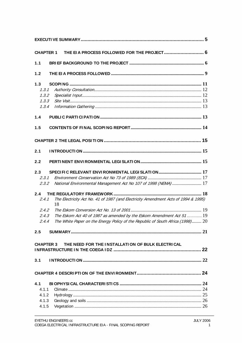
The Coega Industrial Development Zone (IDZ) is located within the Nelson Mandela Metropolitan Municipality, and comprises an industrial development complex covering 28 000 acres (11 500 hectares). It includes the deepwater Port of Ngqura. Proposed IDZ Clusters include Academic and Training, Energy and Automotive, Electronics and Technical, Metals and Metallurgical, an Airport, and a Chemical and Technical Cluster. A Strategic Environmental Assessment (SEA) was carried out for the Coega Project, followed by separate Environmental Impact Assessments (EIAs) for the rezoning of the land for the IDZ, for the construction of the Port of Ngqura, and for mining of the Western Coega Kop Quarry (to obtain rock for the port breakwaters). Once the IDZ is developed, the demand for electricity is expected to be at 5000 megawatts per day, which will be more than what the whole Eastern Cape currently uses. Port Elizabeth is currently using 800 megawatts of power per day. A significant amount of infrastructure is thus required to ensure that the supply of electricity to the IDZ is sustainable. In order to achieve this, Eskom Transmission and the Coega Development Corporation (CDC) propose the installation of high voltage electrical infrastructure within the Coega IDZ. The project includes approximately 20 kilometres of 400kV transmission lines and 26 kilometres of 132kV transmission lines. In addition the project includes the construction of 3 substations, the upgrade of the existing Grassridge substation, and the installation of infrastructure to be used by Eskom Telecommunications. All components of the project except the upgrade to the Grassridge substation will take place within the Coega IDZ boundary. Lower voltage infrastructure such as 11kV and 132 kV lines and substations are already in the construction phase and were subject to separate environmental authorisation.

EYETHU ENGINEERS cc JULY 2006 COEGA ELECTRICAL INFRASTRUCTURE EIA - FINAL SCOPING REPORT 7
Figure 1: Locality Map
EYETHU ENGINEERS cc JULY 2006 COEGA ELECTRICAL INFRASTRUCTURE EIA - FINAL SCOPING REPORT 8
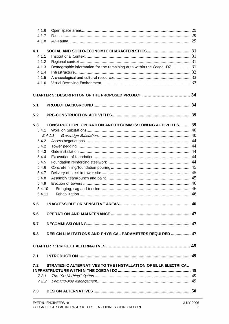
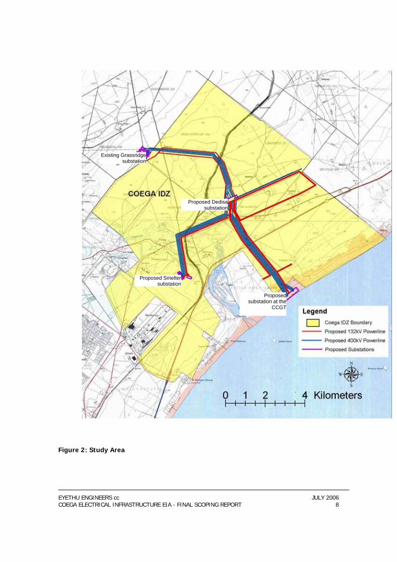
Figure 2: Study Area
Existing Grassridgesubstation
Proposed Dedisasubstation
Proposed Smeltersubstation
Proposedsubstation at the
CCGT
EYETHU ENGINEERS cc JULY 2006 COEGA ELECTRICAL INFRASTRUCTURE EIA - FINAL SCOPING REPORT 9
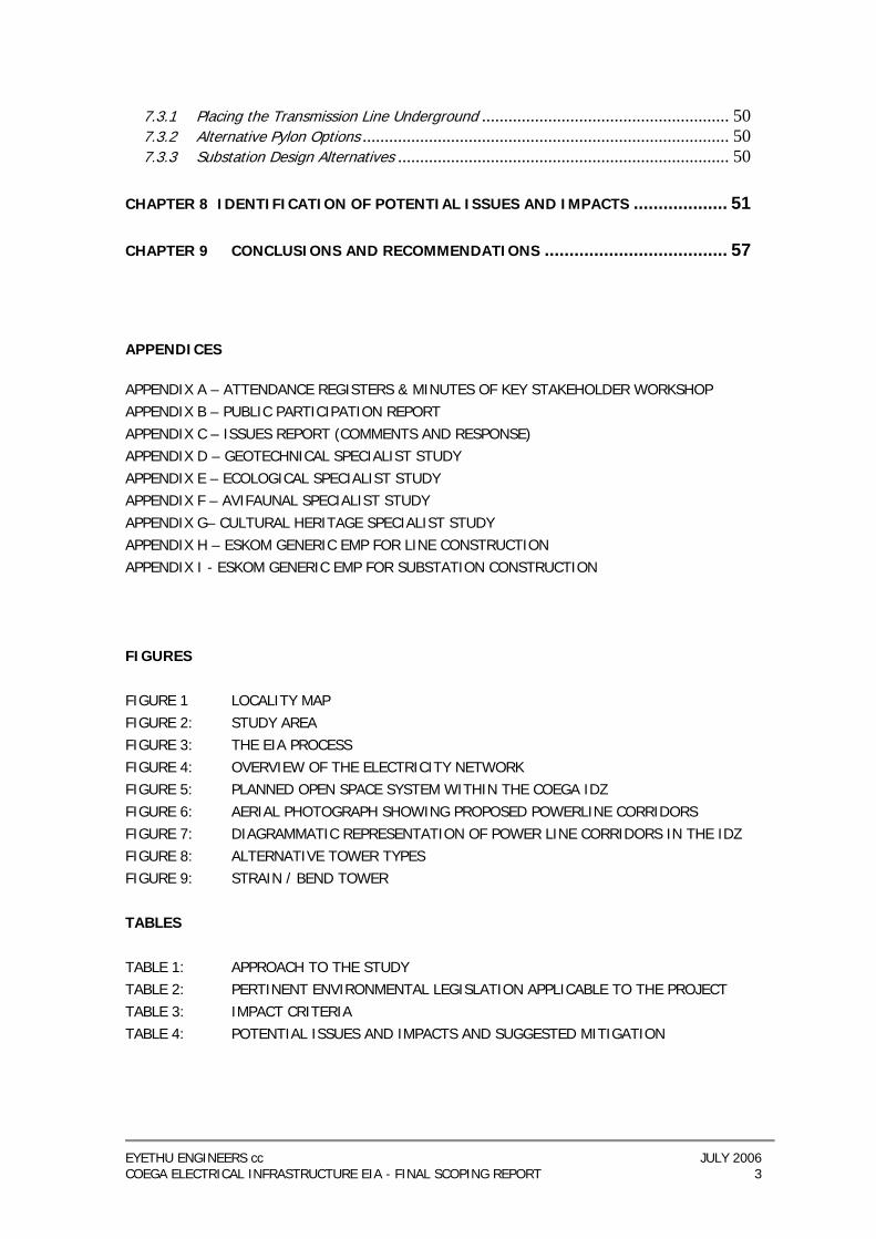
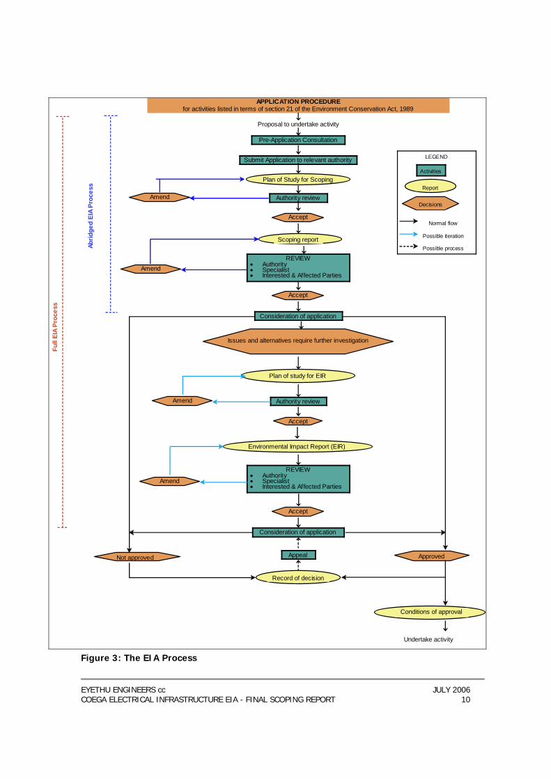
1.2 THE EIA PROCESS FOLLOWED This section provides a background to the EIA process for the project and places this report in the project’s current context. Eyethu Engineers cc were appointed by Eskom Transmission and the Coega Development Corporation to undertake the necessary environmental investigations in order to obtain a Record of Decision (RoD) from the National Department of Environmental Affairs and Tourism (DEAT) on whether the proposed project may proceed or not. Although National DEAT are the decision making authority for the project, their decision requires input from the Eastern Cape Department of Economic Affairs, Environment & Tourism (DEAET). All correspondence between the consultant and National DEAT throughout the scoping process is thus copied to DEAET. The EIA process is carried out according to an Integrated Environmental Management (IEM) procedure, as advocated by the Department of Environmental Affairs and Tourism (1992) and the Regulations promulgated under the Environment Conservation Act No. 73 of 1989. This report is the Final Scoping Report, and constitutes part of the EIA process, as illustrated in Figure 3. The EIA process as a whole is intended to provide information on the study area, identify alternatives at an early stage, facilitate consultation with the landowners, key stakeholders and specialists, and to address the concerns of Interested and Affected Parties (IAPs). This report aims to identify all issues raised during the scoping process and to assess the potential environmental impact of the activity, and thus to provide sufficient information for National DEAT to assess the project at scoping level. Based on the review of the scoping report, National DEAT will rule whether further environmental investigations are required, or they will issue a record of decision at this stage. The RoD will either state that the project may not proceed, or that it may proceed with conditions.
EYETHU ENGINEERS cc JULY 2006 COEGA ELECTRICAL INFRASTRUCTURE EIA - FINAL SCOPING REPORT 10
Record of decision
Pre-Application Consultation
Submit Application to relevant authority
Authority review
Plan of Study for Scoping
Scoping report
APPLICATION PROCEDURE for activities listed in terms of section 21 of the Environment Conservation Act, 1989
Proposal to undertake activity
Accept
Accept
Amend
Amend
Not approved Approved
Consideration of application
Authority review
Consideration of application
Appeal
Issues and alternatives require further investigation
Plan of study for EIR
Environmental Impact Report (EIR)
REVIEW • Authority • Specialist • Interested & Affected Parties
Accept
Accept
Amend
Amend
LEGEND Activities
Report
Decisions
Normal flow
Possible iteration
Possible process
Conditions of approval
Undertake activity
REVIEW • Authority • Specialist • Interested & Affected Parties
Abrid
ged
EIA
Proc
ess
Full
EIA
Proc
ess
Figure 3: The EIA Process
EYETHU ENGINEERS cc JULY 2006 COEGA ELECTRICAL INFRASTRUCTURE EIA - FINAL SCOPING REPORT 11
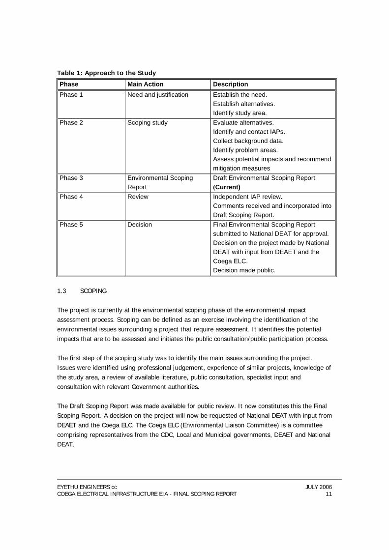
Table 1: Approach to the Study
Phase Main Action Description Phase 1 Need and justification Establish the need.
Establish alternatives. Identify study area.
Phase 2 Scoping study Evaluate alternatives. Identify and contact IAPs. Collect background data. Identify problem areas. Assess potential impacts and recommend mitigation measures
Phase 3 Environmental Scoping Report
Draft Environmental Scoping Report (Current)
Phase 4 Review Independent IAP review. Comments received and incorporated into Draft Scoping Report.
Phase 5 Decision Final Environmental Scoping Report submitted to National DEAT for approval. Decision on the project made by National DEAT with input from DEAET and the Coega ELC. Decision made public.
1.3 SCOPING The project is currently at the environmental scoping phase of the environmental impact assessment process. Scoping can be defined as an exercise involving the identification of the environmental issues surrounding a project that require assessment. It identifies the potential impacts that are to be assessed and initiates the public consultation/public participation process. The first step of the scoping study was to identify the main issues surrounding the project. Issues were identified using professional judgement, experience of similar projects, knowledge of the study area, a review of available literature, public consultation, specialist input and consultation with relevant Government authorities. The Draft Scoping Report was made available for public review. It now constitutes this the Final Scoping Report. A decision on the project will now be requested of National DEAT with input from DEAET and the Coega ELC. The Coega ELC (Environmental Liaison Committee) is a committee comprising representatives from the CDC, Local and Municipal governments, DEAET and National DEAT.
EYETHU ENGINEERS cc JULY 2006 COEGA ELECTRICAL INFRASTRUCTURE EIA - FINAL SCOPING REPORT 12
1.3.1 Authority Consultation A pre-application meeting was held with the following attendees in Pretoria on the 23rd February 2006: − Mr Danie Smit, National Department of Environmental Affairs and Tourism; − Mr John Geeringh, Eskom Transmission − Mr Fezile Ndema, Coega Development Corporation − Ms Sharon Boast, Eyethu Engineers cc See attendance register and minutes in Appendix A. All correspondence including minutes of the pre-application meeting have been copied to Mr Andries Struwig of the DEAET. A key stakeholder workshop was held in the Port Elizabeth City Hall on the 29th March 2006. Local and provincial authorities, as well as NGO’s were invited to attend the Key Stakeholder Workshop (see attendance register and minutes in Appendix A). 1.3.2 Specialist Input The following specialists were consulted concerning the project and produced reports at the scoping stage: − Archaeology: Len van Schalkwyk, eThembeni Cultural Heritage − Avifauna: Jon Smallie, Endangered Wildlife Trust − Ecology: Pete Illgner − Geology: GV Price, Terreco The aims of authority and specialist consultation at this stage were to discuss and define the following: − the need for the project; − alternatives; − any constraints which may be identified by Authorities; − scope of work for the study; − study approach and methodology with respect to data collection, data evaluation and
public participation; − identification of additional interested parties; − the main environmental issues which require detailed study; − relevant data;
EYETHU ENGINEERS cc JULY 2006 COEGA ELECTRICAL INFRASTRUCTURE EIA - FINAL SCOPING REPORT 13
− verification of map data; and − identification of “no go” areas. 1.3.3 Site Visit The project team and specialists undertook a site visit to the Coega IDZ on the 17th of February 2006. The site visit included a flight over the study area in a helicopter, where the substation sites were viewed and the powerline corridors were followed. The team was accompanied by Eskom and Coega personnel in order that technical and strategic questions could be addressed.
1.3.4 Information Gathering
Information gathering was carried out through: − Correspondence with specialists, Eskom and CDC personnel − Literature reviews − Geographic Information System (GIS) analysis including 1:50 000 topographical maps − Red Data Flora information − Vegetation maps of South Africa (Mucina and Rutherford 2003) − Geological maps of southern Africa (Theron 1990) − Heritage Databases for the Eastern Cape − Interaction with NGOs and individuals − Interaction with Authorities 1.4 PUBLIC PARTICIPATION Public participation forms an integral part of the Scoping process. Details of the public participation process followed are provided in Appendix B. An issues report highlighting all issues raised and comments relating to the project is included as Appendix C.
EYETHU ENGINEERS cc JULY 2006 COEGA ELECTRICAL INFRASTRUCTURE EIA - FINAL SCOPING REPORT 14
1.5 CONTENTS OF FINAL SCOPING REPORT Chapter 1 The EIA Process followed for the Project Chapter 2 The Legal Position Chapter 3 The need for the Coega Electrical Infrastructure Project Chapter 4 Description of the Environment Chapter 5 Description of the Proposed Project Chapter 6 Identification of Potential Issues and Impacts Chapter 7 Alternatives Chapter 8 Conclusions and Recommendations
EYETHU ENGINEERS cc JULY 2006 COEGA ELECTRICAL INFRASTRUCTURE EIA - FINAL SCOPING REPORT 15
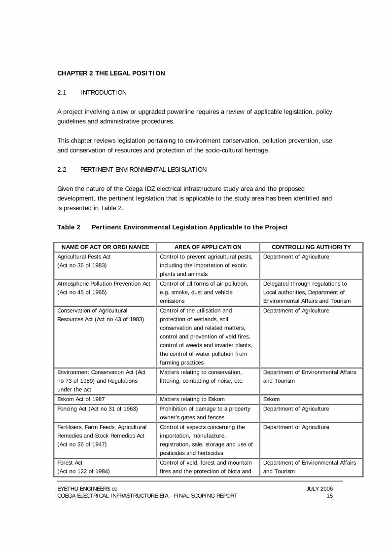
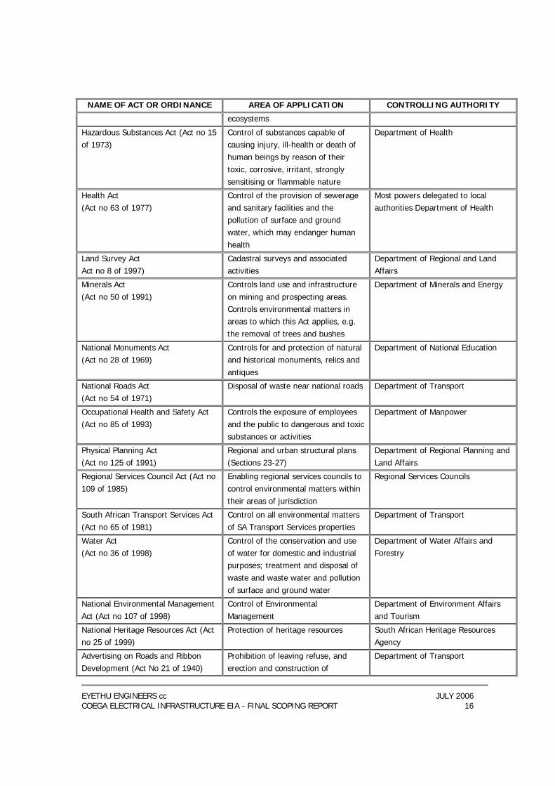
CHAPTER 2 THE LEGAL POSITION 2.1 INTRODUCTION A project involving a new or upgraded powerline requires a review of applicable legislation, policy guidelines and administrative procedures. This chapter reviews legislation pertaining to environment conservation, pollution prevention, use and conservation of resources and protection of the socio-cultural heritage. 2.2 PERTINENT ENVIRONMENTAL LEGISLATION Given the nature of the Coega IDZ electrical infrastructure study area and the proposed development, the pertinent legislation that is applicable to the study area has been identified and is presented in Table 2. Table 2 Pertinent Environmental Legislation Applicable to the Project
NAME OF ACT OR ORDINANCE AREA OF APPLICATION CONTROLLING AUTHORITY
Agricultural Pests Act (Act no 36 of 1983)
Control to prevent agricultural pests, including the importation of exotic plants and animals
Department of Agriculture
Atmospheric Pollution Prevention Act (Act no 45 of 1965)
Control of all forms of air pollution, e.g. smoke, dust and vehicle emissions
Delegated through regulations to Local authorities, Department of Environmental Affairs and Tourism
Conservation of Agricultural Resources Act (Act no 43 of 1983)
Control of the utilisation and protection of wetlands, soil conservation and related matters, control and prevention of veld fires, control of weeds and invader plants, the control of water pollution from farming practices
Department of Agriculture
Environment Conservation Act (Act no 73 of 1989) and Regulations under the act
Matters relating to conservation, littering, combating of noise, etc.
Department of Environmental Affairs and Tourism
Eskom Act of 1987 Matters relating to Eskom Eskom
Fencing Act (Act no 31 of 1963) Prohibition of damage to a property owner’s gates and fences
Department of Agriculture
Fertilisers, Farm Feeds, Agricultural Remedies and Stock Remedies Act (Act no 36 of 1947)
Control of aspects concerning the importation, manufacture, registration, sale, storage and use of pesticides and herbicides
Department of Agriculture
Forest Act (Act no 122 of 1984)
Control of veld, forest and mountain fires and the protection of biota and
Department of Environmental Affairs and Tourism
EYETHU ENGINEERS cc JULY 2006 COEGA ELECTRICAL INFRASTRUCTURE EIA - FINAL SCOPING REPORT 16
NAME OF ACT OR ORDINANCE AREA OF APPLICATION CONTROLLING AUTHORITY
ecosystems
Hazardous Substances Act (Act no 15 of 1973)
Control of substances capable of causing injury, ill-health or death of human beings by reason of their toxic, corrosive, irritant, strongly sensitising or flammable nature
Department of Health
Health Act (Act no 63 of 1977)
Control of the provision of sewerage and sanitary facilities and the pollution of surface and ground water, which may endanger human health
Most powers delegated to local authorities Department of Health
Land Survey Act Act no 8 of 1997)
Cadastral surveys and associated activities
Department of Regional and Land Affairs
Minerals Act (Act no 50 of 1991)
Controls land use and infrastructure on mining and prospecting areas. Controls environmental matters in areas to which this Act applies, e.g. the removal of trees and bushes
Department of Minerals and Energy
National Monuments Act (Act no 28 of 1969)
Controls for and protection of natural and historical monuments, relics and antiques
Department of National Education
National Roads Act (Act no 54 of 1971)
Disposal of waste near national roads Department of Transport
Occupational Health and Safety Act (Act no 85 of 1993)
Controls the exposure of employees and the public to dangerous and toxic substances or activities
Department of Manpower
Physical Planning Act (Act no 125 of 1991)
Regional and urban structural plans (Sections 23-27)
Department of Regional Planning and Land Affairs
Regional Services Council Act (Act no 109 of 1985)
Enabling regional services councils to control environmental matters within their areas of jurisdiction
Regional Services Councils
South African Transport Services Act (Act no 65 of 1981)
Control on all environmental matters of SA Transport Services properties
Department of Transport
Water Act (Act no 36 of 1998)
Control of the conservation and use of water for domestic and industrial purposes; treatment and disposal of waste and waste water and pollution of surface and ground water
Department of Water Affairs and Forestry
National Environmental Management Act (Act no 107 of 1998)
Control of Environmental Management
Department of Environment Affairs and Tourism
National Heritage Resources Act (Act no 25 of 1999)
Protection of heritage resources South African Heritage Resources Agency
Advertising on Roads and Ribbon Development (Act No 21 of 1940)
Prohibition of leaving refuse, and erection and construction of
Department of Transport
EYETHU ENGINEERS cc JULY 2006 COEGA ELECTRICAL INFRASTRUCTURE EIA - FINAL SCOPING REPORT 17
NAME OF ACT OR ORDINANCE AREA OF APPLICATION CONTROLLING AUTHORITY
structures near certain roads
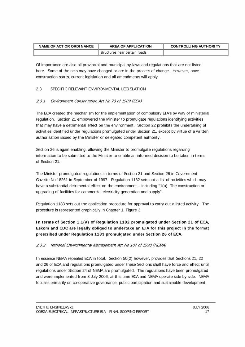
Of importance are also all provincial and municipal by-laws and regulations that are not listed here. Some of the acts may have changed or are in the process of change. However, once construction starts, current legislation and all amendments will apply. 2.3 SPECIFIC RELEVANT ENVIRONMENTAL LEGISLATION 2.3.1 Environment Conservation Act No 73 of 1989 (ECA) The ECA created the mechanism for the implementation of compulsory EIA’s by way of ministerial regulation. Section 21 empowered the Minister to promulgate regulations identifying activities that may have a detrimental effect on the environment. Section 22 prohibits the undertaking of activities identified under regulations promulgated under Section 21, except by virtue of a written authorisation issued by the Minister or delegated competent authority. Section 26 is again enabling, allowing the Minister to promulgate regulations regarding information to be submitted to the Minister to enable an informed decision to be taken in terms of Section 21. The Minister promulgated regulations in terms of Section 21 and Section 26 in Government Gazette No 18261 in September of 1997. Regulation 1182 sets out a list of activities which may have a substantial detrimental effect on the environment – including “1(a) The construction or upgrading of facilities for commercial electricity generation and supply”. Regulation 1183 sets out the application procedure for approval to carry out a listed activity. The procedure is represented graphically in Chapter 1, Figure 3. In terms of Section 1.1(a) of Regulation 1182 promulgated under Section 21 of ECA, Eskom and CDC are legally obliged to undertake an EIA for this project in the format prescribed under Regulation 1183 promulgated under Section 26 of ECA.
2.3.2 National Environmental Management Act No 107 of 1998 (NEMA)
In essence NEMA repealed ECA in total. Section 50(2) however, provides that Sections 21, 22 and 26 of ECA and regulations promulgated under these Sections shall have force and effect until regulations under Section 24 of NEMA are promulgated. The regulations have been promulgated and were implemented from 3 July 2006, at this time ECA and NEMA operate side by side. NEMA focuses primarily on co-operative governance, public participation and sustainable development.
EYETHU ENGINEERS cc JULY 2006 COEGA ELECTRICAL INFRASTRUCTURE EIA - FINAL SCOPING REPORT 18
Section 2 of the act sets out a series of principles which serve as guidelines “by reference to which any organ of state must exercise any function when taking any decision in terms of this act or any statutory provision concerning the protection of the environment.” These principles include: − The development must be sustainable. − Pollution must be avoided or minimised and remedied. − Negative impacts must be minimised and positives enhanced. − Waste must be avoided or minimised, reused or recycled. Section 2(4)(vii) effectively writes into law the “precautionary principle”, whereby a risk-averse and cautious approach is applied to the decision-making process. Section 28 imposes a duty of care to avoid environmental damage or pollution, and where it is not possible to avoid this by taking reasonable steps, then imposes an obligation to remediate any environmental damage that may occur as a result of the activity. 2.4 THE REGULATORY FRAMEWORK
2.4.1 The Electricity Act No. 41 of 1987 (and Electricity Amendment Acts of 1994 & 1995)
This Act governs the control of generation and supply of electricity in South Africa and the existence and functions of the Electricity Control Regulator (National Energy Regulator). Section 3 of the Act sets out the objectives of the Regulator, which are to exercise control over the electricity supply industry so as to ensure order in the generation and supply of electricity, and to perform all functions assigned to it under the Act. “Supply” is defined as the provision or distribution of electricity or both. Section 4 sets out the functions of the regulator that are inter alia, that the regulator may: (a) issue licences for the generation, provision and, within the area determined by it,
distribution of electricity. (b) determine the prices at and conditions on which electricity may be supplied by a licensee. The Board of the NER consists of a chairperson and eight part-time members, all of whom are knowledgeable and experienced in broader electricity supply issues. Board members are appointed by the Minister of Minerals and Energy Affairs and are funded predominantly from licence fees levied on the licence in respect of electricity generated or supplied.
EYETHU ENGINEERS cc JULY 2006 COEGA ELECTRICAL INFRASTRUCTURE EIA - FINAL SCOPING REPORT 19
Section 6 stipulates that no person shall generate or supply electricity except under the authority of a licence. Section 10 sets out duties of licensees which includes inter alia that the licensee must supply electricity to every applicant within his licence area, who is in a position to make satisfactory arrangements for payment thereof. Should the licence unduly delay or refuse to supply the applicant may appeal to the regulator, who will decide whether the licensee shall supply the applicant and the conditions for such supply. Section 12 gives the regulator power to give a defaulting licensee 30 days, or such longer period as may be required, to meet his obligations. Failure to comply may result in a criminal conviction, the taking of possession of the undertaking of the licensee or the withdrawal of his licence. At present Eskom and over 400 distributors - mainly municipal electricity departments-supply electricity to end customers. Eskom is the largest single distributor in the country in terms of sales for final consumption and number of customers. The municipal distributors are under direct control of elected local councils. All electricity distributors are subject to regulation by the NER. The current electricity distribution industry is fragmented and a restructuring and consolidation process has commenced whereby six (6) Regional Electricity Distributors (REDs) and Eskom will be responsible for distribution and transmission of electricity 2.4.2 The Eskom Conversion Act No. 13 of 2001 The objective of the Eskom Conversion Act is to convert Eskom into a public company having a share capital in terms of the companies Act, and to provide for matters connected therewith, such as powers and duties of Eskom. Section 2A stipulates that the ownership of Eskom’s equity shall rest in the State. Section 3 sets out the objectives of Eskom which is “to provide the system by which the electricity needs of the consumer may be satisfied in the most cost-effective manner, subject to resource constraints and the nations interest”. 2.4.3 The Eskom Act 40 of 1987 as amended by the Eskom Amendment Act 51 of 1991 Section 3 of the Act sets out the objectives of Eskom, being inter alia the provision of a system by which electricity needs of the consumer may be satisfied in the most cost effective manner, subject to resource constraints and the national interest.
EYETHU ENGINEERS cc JULY 2006 COEGA ELECTRICAL INFRASTRUCTURE EIA - FINAL SCOPING REPORT 20
The Electricity Council exercises control over the performance of Eskom’s functions and the exercise of its powers and duties. (Sect 4 (1)). The management of the affairs of Eskom are conducted by the Management Board (Sect 4(4)), the members of which are appointed by the Electricity Council. Section 11 authorises Eskom to generate or supply or to generate and supply electricity within the Republic of South Africa subject to the right of local authorities and holders of licences under the provisions of the Electricity Act, 1987. Section 12 sets out the functions, powers and duties of Eskom, which include inter alia: 1(a) the power to investigate, establish, acquire, maintain, co-ordinate, amalgamate and carry on undertakings to provide an efficient and cost-effective supply of electricity to any body or person in the republic. 1(aa) to enter into any contract or perform any act …. As will in the opinion of the Electricity Council contribute towards the attainment of Eskom’s objectives. 2.4.4 The White Paper on the Energy Policy of the Republic of South Africa (December 1998)
White Papers are policy documents and hence lack the legal force of legislation. They are however indicative of the government’s plans and future policies and often result in the tabling of legislation to achieve the policies and goals set out therein. In 1998 the government published its White Paper on the Energy Sector of South Africa. Energy sector policy objectives identified include increasing access to affordable energy services, improving energy governance, stimulating economic development (including the encouragement of cost-effective energy prices which include quantifiable externalities), managing energy-related environmental and health impacts and securing supply through diversity. There is a recognition that there needs to be a balance between energy prices and sustainable environmental standards. The White Paper recognises that electricity industry is effectively a state monopoly, which is tightly regulated by government policies and regulators and commits the Government to encourage competition within energy markets, particularly in the generation sector, with the introduction of Independent Power Producers (IPP).
EYETHU ENGINEERS cc JULY 2006 COEGA ELECTRICAL INFRASTRUCTURE EIA - FINAL SCOPING REPORT 21
2.5 SUMMARY To summarise: Eskom has a number of legal obligations arising out of various statutes that are applicable in this context, the key aspects being: (a) An obligation to supply electricity to every person applying for electricity who is in a
position to pay for it, in the most effective manner, subject to resource constraints and the national interest.
(b) An obligation to undertake an EIA for activities which fall within the scope of
Regulation 1182 promulgated in terms of ECA and / or the National Resources Heritage Act.
(c) Various obligations to prevent environmental damage by taking all reasonable steps to
prevent it (NEMA, National Water Act and others).
EYETHU ENGINEERS cc JULY 2006 COEGA ELECTRICAL INFRASTRUCTURE EIA - FINAL SCOPING REPORT 22
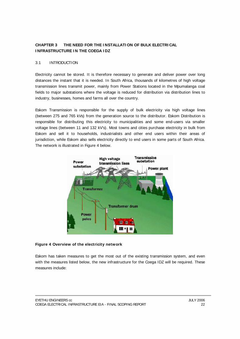
CHAPTER 3 THE NEED FOR THE INSTALLATION OF BULK ELECTRICAL INFRASTRUCTURE IN THE COEGA IDZ 3.1 INTRODUCTION Electricity cannot be stored. It is therefore necessary to generate and deliver power over long distances the instant that it is needed. In South Africa, thousands of kilometres of high voltage transmission lines transmit power, mainly from Power Stations located in the Mpumalanga coal fields to major substations where the voltage is reduced for distribution via distribution lines to industry, businesses, homes and farms all over the country. Eskom Transmission is responsible for the supply of bulk electricity via high voltage lines (between 275 and 765 kVs) from the generation source to the distributor. Eskom Distribution is responsible for distributing this electricity to municipalities and some end-users via smaller voltage lines (between 11 and 132 kV’s). Most towns and cities purchase electricity in bulk from Eskom and sell it to households, industrialists and other end users within their areas of jurisdiction, while Eskom also sells electricity directly to end users in some parts of South Africa. The network is illustrated in Figure 4 below.
Figure 4 Overview of the electricity network Eskom has taken measures to get the most out of the existing transmission system, and even with the measures listed below, the new infrastructure for the Coega IDZ will be required. These measures include:
EYETHU ENGINEERS cc JULY 2006 COEGA ELECTRICAL INFRASTRUCTURE EIA - FINAL SCOPING REPORT 23
− Comprehensive checks on the existing lines to ensure that they are within the legal clearance for overhead lines. Lines sag when placed under heavy load conditions, due to heating of the conductors.
− Installation of line monitoring devices that measure the prevailing atmospheric
conditions. This allows Eskom to decide whether the lines can cope with more loading (e.g. on a cold day the line can be loaded to more than usual levels since the lines cool down and they do not sag as much.)
− When reinforcement options were looked at, the best option was chosen to ensure that
an optimised mix of cost, technical benefit and environmental impact was achieved. Eskom planners forecast that once the IDZ develops, the demand for electricity is expected to be at 5000 megawatts, which will be more than the whole Eastern Cape currently uses (Port Elizabeth is currently using 800 megawatts). In addition to bringing power to the IDZ, the bulk infrastructure also needs to serve the purpose of integrating the proposed power generation plant (Closed Cycle Gas Turbine - CCGT) into the country’s electricity network.

EYETHU ENGINEERS cc JULY 2006 COEGA ELECTRICAL INFRASTRUCTURE EIA - FINAL SCOPING REPORT 24
CHAPTER 4 DESCRIPTION OF THE ENVIRONMENT The information contained in this section provides a broad overview of the environmental context within which the proposed project would take place, if approved. It is anticipated that much of the study area will be transformed and developed for the IDZ. The layout of the remaining open areas can be seen below in Figure 5 (the IDZ’s planned open space system). For the purposes of this study emphasis has been placed on what will remain once the IDZ has been developed (this has already received environmental authorisation), rather than what is currently present. Should any gaps in the information be identified that make decision-making difficult, components of the affected environment may need to be examined in more detail. 4.1 BIOPHYSICAL CHARACTERISTICS The IDZ boundary is regarded as the study area for the purposes of this report, although focus has been placed on the development footprints of the components of the power distribution network. 4.1.1 Climate
The climate of this region is complex as it experiences the overlapping of both temperate and subtropical climatic regimes. The Coega area has a warm temperate climate and the temperature ranges are not extreme, except during summer. Average maximum and minimum monthly temperatures for Port Elizabeth (which is 20km away from Coega), are shown in the table below. Average monthly temperatures (°C) for Port Elizabeth (1957 - 2002)
Jan Feb Mar Apr May Jun Jul Aug Sep Oct Nov Dec Min 16.8 17 16 13.6 10.8 8.5 8.1 9.2 10.7 12.5 14 15.6 Max 24.3 24.4 23.5 22 20.7 19.5 19 18.8 19.1 20 21.4 23.2 Rainfall peaks for the Coega area occur in Spring and Autumn. Annual rainfall in the Port Elizabeth region ranges from 440 mm to 820 mm. The Coega area receives approximately 400 mm of rain annually with rain occurring throughout the year. The long-term average rainfall data for Port Elizabeth for the period 1970 to 2004 is given in the table below. Average monthly rainfall (mm) listed for Port Elizabeth (1970 - 2004)
Jan Feb Mar Apr May Jun Jul Aug Sep Oct Nov Dec Total Ave
36.8 39.5 51.4 50 51.1 56.8 49.1 71.6 52.8 57.8 57.9 43.4 618 Prevailing winds along the coast tend to follow the coastline and the winds in the Port Elizabeth area are from the West-South-West and East-North-East. The dominant prevailing winds are west to south-south westerly, at times changing to east to east north easterly. The Coega area
EYETHU ENGINEERS cc JULY 2006 COEGA ELECTRICAL INFRASTRUCTURE EIA - FINAL SCOPING REPORT 25
experiences strong winds with a prevalence from the west and west-south-west all year round, and east from October to March. Light winds are also experienced in the area and are more variable in direction, especially in winter. 4.1.2 Hydrology
4.1.2.1 Surface water
The Coega catchment area is approximately 45 km long, 15 km wide and has a total area of about 550 km2. The Coega River, which is a relatively small sand-bed river, is the most significant surface water feature associated with the Coega IDZ. The Coega River classification, based on preliminary river classification guidelines, ranges from moderately modified (i.e. C classification) in the upper reaches to critically modified (i.e. F classification) in the lower reaches at the salt works facility. Low permeability clays underlying the study area limit the vertical infiltration of rainwater and produce a horizontal groundwater flow towards the river channel. Consequently, rapid run-off takes place following precipitation. Due to the limited infiltration of rainfall, a significant fluctuation in groundwater level does not occur, although groundwater levels can fluctuate by 3-4 m with rainfall. 41.2.2 Groundwater
The southern portion of the Coega IDZ is underlain at depth by an artesian aquifer formed by the sandstones and quartzites of the Table Mountain Group. Confining this aquifer is a succession of eastward-thickening Cretaceous formations (Uitenhage Group) up to 1 200 m thick near the coast. It is one of the few artesian systems in southern Africa and the only one of practical importance in the country (SRK 2005). This artesian system was protected under Government Proclamation No. 260 of 1957 and No. 958 of 1958, but the rights of access to this water will probably alter in the light of the new National Water Act (Act No. 36 of 1998). Overexploitation of the aquifer has led to several periods where artesian yields have dropped, which led to the regulation of drilling and abstraction. Groundwater quality in the Coega Ridge Aquifer deteriorates relatively little along the flow path from west to east and has been carbon fourteen dated at 28 000 years near Coega Kop. In general, the water is mildly acidic due to oxidation of pyrite in the Table Mountain Group. Groundwater levels at Coega are generally about 3 to 5 m below surface, i.e. just above the contact between the permeable sands and the underlying impermeable clays. The groundwater flow direction is to the southeast, following the surface water drainage direction. The shallow groundwater is consistently characterised by a high natural salinity and total dissolved solids content.
EYETHU ENGINEERS cc JULY 2006 COEGA ELECTRICAL INFRASTRUCTURE EIA - FINAL SCOPING REPORT 26
4.1.3 Geology and soils A geotechnical study was carried out by Terreco as part of the scoping process and can be found in Appendix D. The general geological environment of the study area comprises Cretaceous to Recent Age, generally soft rock, weathered, sedimentary rocks. Relatively recent, in terms of geological age, transgressive marine depositions resulted in peneplanation of the surface topography, providing the relic flat-topped plateaus characterising the area. Geomorphological processes have since carved the deeply incised interstitial gullies and valleys which truncate the terrain. The geological strata are generally near-horizontal, resulting in complete stratigraphic exposure of the geological legend through erosion by steeply incised flow lines. This allows accurate mapping with easy location of exploitable minerals for road building, brick-making and construction aggregates. Those available are currently being exploited, and while the electrical footprint is relatively thin, checks must be in place to see that existing facilities are not compromised and future opportunities protected. Current opportunities include sand/gravel borrowing; deep excavation of Sundays River mudstone for brick-making, and exploitation of salt brine from shallow seawater pans. A large brick borrow pit is located in the central part of the study area but both it and the actual brick-making plant area are located well outside the pylon/cable footprint with extensive material reserves located away from this zone. The footprint transects other areas with potential but reserves are so extensive that the thin zone establishing electricity for the IDZ should not impinge on future opportunities. Sand and gravel calcrete borrowing has occurred from time to time but in a haphazard manner and at various points along the Coega River floodplain. These raised platform deposits are extensive in the area and where the ‘footprint’ crosses these presents only a thin slice of extensive other opportunities. Borrowing can in any case continue, with permission from Eskom, beneath the electric cables, should this be required. Salt mining from pans continues in the river floodplain east of the National Route 2. The Eskom footprint is located far off all of these.
4.1.5 Vegetation An ecological study was undertaken in March 2006 by ecological specialist Pete Illgner (Please refer to Appendix E). According to Illgner (2006), the Nelson Mandela Metropolitan Open Space System (NM MOSS; Stewart et al. 2004) recognizes a number of distinct vegetation types within the Coega IDZ. These correspond with the STEP (Subtropical Thicket Ecosystem Planning project;
EYETHU ENGINEERS cc JULY 2006 COEGA ELECTRICAL INFRASTRUCTURE EIA - FINAL SCOPING REPORT 27
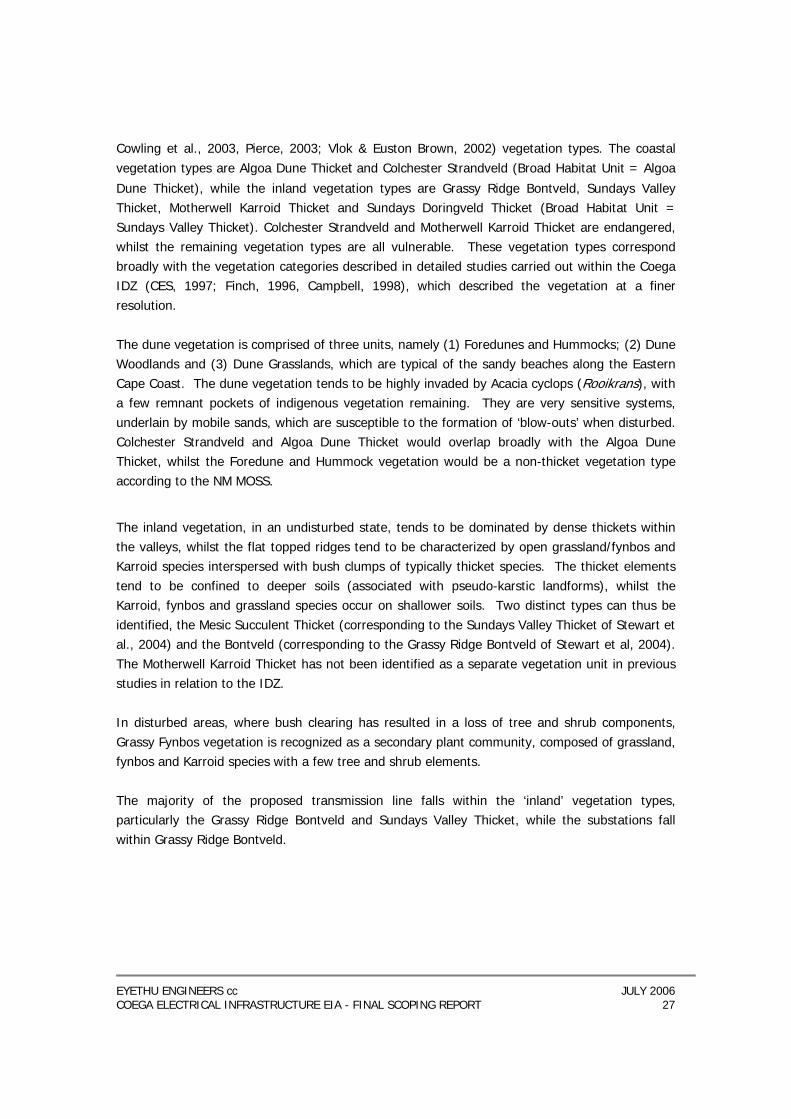
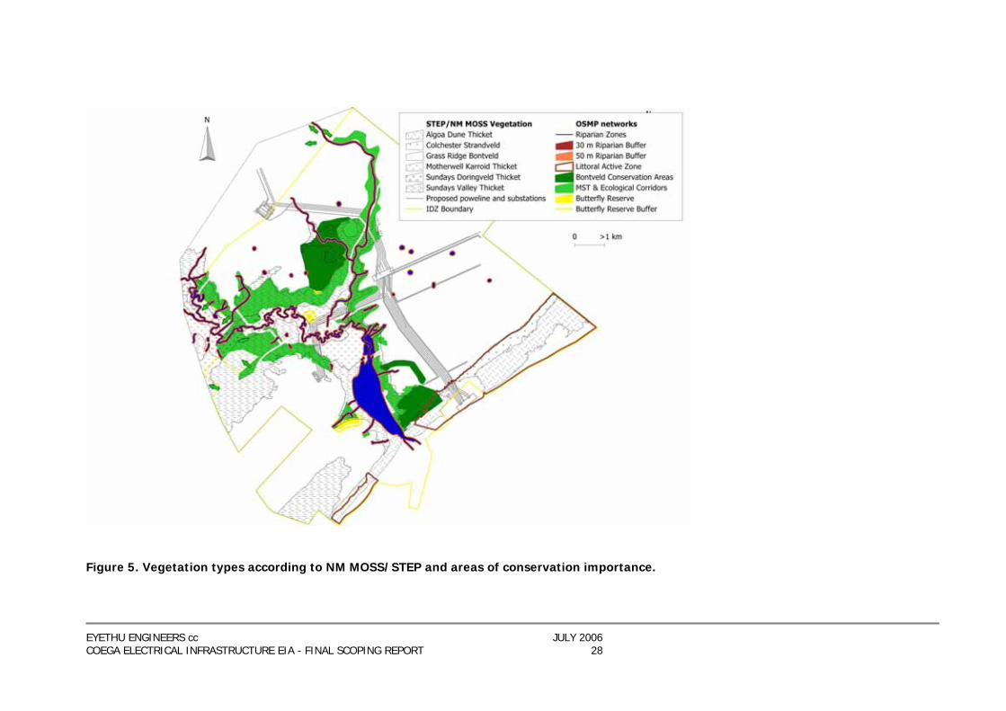
Cowling et al., 2003, Pierce, 2003; Vlok & Euston Brown, 2002) vegetation types. The coastal vegetation types are Algoa Dune Thicket and Colchester Strandveld (Broad Habitat Unit = Algoa
Dune Thicket), while the inland vegetation types are Grassy Ridge Bontveld, Sundays Valley Thicket, Motherwell Karroid Thicket and Sundays Doringveld Thicket (Broad Habitat Unit = Sundays Valley Thicket). Colchester Strandveld and Motherwell Karroid Thicket are endangered, whilst the remaining vegetation types are all vulnerable. These vegetation types correspond broadly with the vegetation categories described in detailed studies carried out within the Coega IDZ (CES, 1997; Finch, 1996, Campbell, 1998), which described the vegetation at a finer resolution. The dune vegetation is comprised of three units, namely (1) Foredunes and Hummocks; (2) Dune Woodlands and (3) Dune Grasslands, which are typical of the sandy beaches along the Eastern Cape Coast. The dune vegetation tends to be highly invaded by Acacia cyclops (Rooikrans), with a few remnant pockets of indigenous vegetation remaining. They are very sensitive systems, underlain by mobile sands, which are susceptible to the formation of ‘blow-outs’ when disturbed. Colchester Strandveld and Algoa Dune Thicket would overlap broadly with the Algoa Dune Thicket, whilst the Foredune and Hummock vegetation would be a non-thicket vegetation type according to the NM MOSS.
The inland vegetation, in an undisturbed state, tends to be dominated by dense thickets within the valleys, whilst the flat topped ridges tend to be characterized by open grassland/fynbos and Karroid species interspersed with bush clumps of typically thicket species. The thicket elements tend to be confined to deeper soils (associated with pseudo-karstic landforms), whilst the Karroid, fynbos and grassland species occur on shallower soils. Two distinct types can thus be identified, the Mesic Succulent Thicket (corresponding to the Sundays Valley Thicket of Stewart et al., 2004) and the Bontveld (corresponding to the Grassy Ridge Bontveld of Stewart et al, 2004). The Motherwell Karroid Thicket has not been identified as a separate vegetation unit in previous studies in relation to the IDZ. In disturbed areas, where bush clearing has resulted in a loss of tree and shrub components, Grassy Fynbos vegetation is recognized as a secondary plant community, composed of grassland, fynbos and Karroid species with a few tree and shrub elements. The majority of the proposed transmission line falls within the ‘inland’ vegetation types, particularly the Grassy Ridge Bontveld and Sundays Valley Thicket, while the substations fall within Grassy Ridge Bontveld.
EYETHU ENGINEERS cc JULY 2006 COEGA ELECTRICAL INFRASTRUCTURE EIA - FINAL SCOPING REPORT 28
Figure 5. Vegetation types according to NM MOSS/STEP and areas of conservation importance.
EYETHU ENGINEERS cc JULY 2006 COEGA ELECTRICAL INFRASTRUCTURE EIA - FINAL SCOPING REPORT 29
4.1.6 Open space areas An area of approximately 2 167 ha, spanning both the Core Development Area and the remainder of the IDZ, has been set aside as the primary open space network and will be managed in accordance with the CDC’s approved Open Space Management Plan. The Open Space Management Plan has not only been designed to ensure the protection of the environmentally sensitive areas within the IDZ, but also to provide for active and passive recreation areas where the public can have freedom of movement (SRK 2005). The primary open space network consists of environmentally sensitive areas such as Bontveld conservation areas, dense Mesic succulent thicket on steep slopes, butterfly habitat, grave sites, the riparian zone, the 1:100 year floodline and the coastal dune area.
4.1.7 Fauna Two ‘Rare’ butterflies, namely the Coega Copper (Aloeides clarki) and Wineland Blue (Lepiodchrysops bacchus) occur within the study area. Butterfly reserves have been set aside within the IDZ (see Figure 5). The presence of the Addo Flightless Dung Beetle (Circellium bacchus) in the study area is unknown, although it is known to occur at Colchester close by (Illgner 2006). At least five endemic species of reptile (two of which are endangered) occur within the study area. In addition, endangered sea turtles, and certain CITES-listed species are present, necessitating careful adherence to the project’s Environmental Management Plan. The Albany adder is a protected species and, although not recorded to date within the greater Coega IDZ, the species does appear to be found in association with Bontveld habitats, and the only known population is within close proximity to the Coega IDZ. At least one endemic and Endangered species, namely the Albany dwarf adder (Bitis albanica) and three other endemic species (Tasman’s girdled lizard, Cordylus tasmani; Dwarf burrowing skink, Scelotes anguineus and Eastern legless skink, Acontias (meleagris) orientalis) are known to occur inside or in close proximity (< 2km) to the IDZ, (Illgner 2006).
4.1.8 Avi-Fauna A full list of bird species occurring in the study area can be found in Appendix F – specialist Avi-fauna report. A total of 32 Red Data species were recorded, including two “endangered”, eight “vulnerable” and 22 “near threatened”. In addition, the White Stork was included as although it is not a Red Data species, it is protected internationally under the Bonn Convention on Migratory Species. Since much of the natural vegetation currently present in the study area will be transformed as the IDZ develops, the following description of micro habitats that will remain available to
EYETHU ENGINEERS cc JULY 2006 COEGA ELECTRICAL INFRASTRUCTURE EIA - FINAL SCOPING REPORT 30
birds after the proposed transformation is all the more relevant. The bird micro habitats described below were identified during the field investigation:
4.1.8.1 Rivers/drainage lines Most rivers in southern Africa are in the east and extreme south, in the higher rainfall areas. Thirteen species of water bird are mostly restricted to riverine habitat in southern Africa. The map distribution of these species correlates with the river courses in southern Africa. In this study area, several smallish streams were identified. These streams serve as important habitat for some species as well as important flight paths for many bird species even when dry.
4.1.8.2 Estuary
Estuaries are coastal wetland systems typically associated with river mouths. They represent
the interface between freshwater and salt water systems. Most estuaries occur on the east
coast of South Africa. In this study area the Coega River estuary is of great importance to a
number of bird species including the Red Data species shown in Appendix F (Avifaunal
Specialist Study).
4.1.8.3 Salt works
Salt works are an important type of artificial wetland. Species that benefit from these areas
are Chestnut-banded Plover and the Greater and Lesser Flamingoes. Although the salt works
at Coega will be discontinued when the full IDZ development takes place, it seems likely that
the physical characteristics (i.e. extensive shallow water areas) of the site will not be altered
significantly meaning that it will continue to represent important habitat to these bird species.
The Port of Ngqura will continue up the Coega River and hence the shallow pans will
disappear. The Sundays River Solar Works, near Colchester, may therefore attract more birds.
4.1.8.4 Shoreline
The coast line of South Africa represents the interface between land and sea and is
characterized by an exposed shoreline with strong wave action. The average tidal range is 1
metre so the inter-tidal zone is relatively narrow. There are relatively few bays providing
sheltered shorelines along the coast. In this study area the coast line consists mainly of sandy
beaches. Although the shore itself will not be traversed by the proposed power lines, its close
proximity will influence the presence, abundance and movement of various bird species and
so is relevant to this study.
4.1.8.5 Natural vegetation – bontveld, fynbos, remnant valley bushveld
This has been discussed above under vegetation description – areas of natural vegetation
that will remain once the IDZ is developed can be seen in Figure 5.
EYETHU ENGINEERS cc JULY 2006 COEGA ELECTRICAL INFRASTRUCTURE EIA - FINAL SCOPING REPORT 31
2.2.6 Coastal Dune Area
This is the area immediately above or inland of the high water mark. It is currently identified
as a “low intensity use area” for the development of boardwalks, trails and look-out spots. It
appears however that this would clash with the construction of the proposed 9 overhead
power lines that will connect the grid to the Gas Power Station.
Tinley (1985) had the following to say about this area, often called the Littoral Active Zone in
Illgner & Pote (2006) - "Roads, railways, bridges, powerlines, parking lots, houses and any
other immovable structure must not be placed within reach of the littoral active zone." This
more or less clarifies the sensitivity of this micro habitat in terms of broader ecology, which
would obviously include avifauna.
4.1 SOCIAL AND SOCIO-ECONOMIC CHARACTERISTICS
4.1.1 Institutional Context
The Coega Industrial Development Zone falls within the Eastern Cape Province of South
Africa. The IDZ is situated within ward 54 of the Nelson Mandela Municipal Metro (NMMM).
There is no tribal authority for this area.
4.1.2 Regional context
The nearest city to the Coega IDZ is Port Elizabeth which is South Africa’s fifth largest city.
Other settlements in close proximity to the Coega IDZ are Colchester, Cannonville,
Motherwell, Bluewater Bay and Wells Estate.
The total population of the NMMM area is approximately 1 300 000 people (NMMM 2005).
Approximately 52 % are female and 37 % are below the age of 20. There are considerable
discrepancies in the standard of living of the different population groups: the white and Asian
communities live in conditions that could be described as developed world with adequate
access to educational, recreational and health facilities, while black communities live in
developing world conditions. The black community experiences the highest levels of poverty
and unemployment, with least access to these facilities, particularly in the Motherwell area
near Coega.
4.1.3 Demographic information for the remaining area within the Coega IDZ
There are currently no people living in the remaining area within the IDZ (Coega
Development Corporation). All people living in the IDZ were relocated in June 2001. The
CDC was required to resettle communities, since no residential areas are allowed within an
IDZ. Three communities living within the Core Development Area of the IDZ were relocated
to Wells Estate Phase 1. They were the King Neptune Community located near Joorst Park,
consisting of 45 households, the Council Grounds community located west of the water pipe
EYETHU ENGINEERS cc JULY 2006 COEGA ELECTRICAL INFRASTRUCTURE EIA - FINAL SCOPING REPORT 32
and close to the Truckers Inn and the Coega community located east of the water pipe,
consisting of 300 households (SRK 2005).
4.1.4 Infrastructure
4.1.4.1 Water and sanitation
The development of the Coega IDZ will substantially increase the consumption of water
within the NMMM. Water is currently purchased by the metro from DWAF and is sourced from
the Orange River Scheme and the groundwater source of the Uitenhage Artesian System. 4.1.4.2 Waste disposal The NMMM currently disposes its general, non-hazardous waste at two permitted solid waste
disposal sites; the Koedoeskloof landfill site and the Arlington landfill site. The municipality
further relies of a network of approximately 50 waste transfer stations to transport waste
from under-serviced and peri-urban areas, to these two landfill sites. The NMMM’s Integrated
Waste Management Plan aims to phase out un-permitted sites that service areas such as
Colchester; i.e. by replacing them with waste transfer stations.
Hazardous waste is currently disposed of at the privately owned Aloes II hazardous waste
facility (permitted Class H:H facility) or the municipally owned Koedoeskloof hazardous waste
facility (permitted H;h). The Koedoeskloof hazardous waste facility is limited in the types and
volumes of hazardous waste that may be disposed, and the Aloes II hazardous waste facility
is nearing capacity. The CDC and the NMMM have therefore identified the need for the
establishment of a new regional general and hazardous waste processing facility in the
Eastern Cape to serve the metropolitan and surrounding areas, including the needs of the
Coega IDZ. In this regard, a site selection process has been undertaken, whereby two sites
have been identified as suitable. An EIA process is currently underway to assess the
feasibility of both sites for the establishment of a hazardous waste site. 4.1.4.3 Transport The NMMM has an extensive transport system, including road, sea, air and rail facilities. The
lower income community is highly dependent on public transport. Taxis are the most
commonly used mode of transport, while other modes of transport include private vehicles,
commuter trains and buses. The Algoa Bus Services is the only licensed service provider
operating in the NMMM and adjacent rural areas. Most residential and industrial areas fall
within a maximum walking distance of 750 m from the nearest bus stop. There is a fleet of
over 2 000 taxis licensed to provide transport within the NMMM and surrounding rural areas.
These taxis compete directly with the Algoa Bus Service and also command a bigger market
share because of the flexibility of stops and journey times. A transport forum has therefore
been established in an attempt to co-ordinate transport activities and address problems
regarding road transport.
EYETHU ENGINEERS cc JULY 2006 COEGA ELECTRICAL INFRASTRUCTURE EIA - FINAL SCOPING REPORT 33
The existing rail network and station placement does not provide accessibility to and from the
low-income residential areas. Grassridge, Aloes and Coega stations are located within the
boundary of the IDZ. These stations currently only handle freight and are not for commuters.
A commuter railway service, including stations, is planned within the Coega IDZ. It will form
a circular line through the IDZ and will be integrated with the existing rail network. 4.1.4.4 Power supply The development of the Coega IDZ has necessitated the augmentation of the existing power
supply to the area. The transmission capacity of the Grassridge substation will therefore be
expanded, which will serve the requirements of the Coega IDZ. An EIA, including route
selection process, is currently underway in order to determine the best route for additional
powerlines to service the IDZ.
4.1.5 Archaeological and cultural resources
A desktop archaeological assessment of the proposed site was conducted by Len van
Schalkwyk of eThembeni Cultural Heritage (See Appendix G), followed up by a site visit to
inspect the route visually for any historical or archaeological material that may be impacted
upon by the proposed upgrade.
The general area is one of variable heritage resource significance, with sites recorded from
both the Stone and Iron Ages. A range of heritage resources has been recorded within and
adjacent to the study area. These include Early, Middle and Later Stone Age sites, Early and
Late Iron Age sites and sites from the historical period.
The region is significant in historic times as a frontier between hunter-gatherers, pastoralists,
Nguni-speaking farming communities and European settlers. As a consequence of contact
between people on the frontier, historical sites occur widely throughout the area and include
domestic, trade, war and battle sites and trade routes.
It is suggested that a detailed archaeological assessment take place once actual tower
positions and substation boundaries have been finalised. It is further recommended that site
staff be made aware of the possibility of uncovering items of historical / cultural significance
and are able to identify these. The EMP for the project should outline the steps to be followed
to minimise the impact on cultural heritage.
4.1.6 Visual Receiving Environment
Due to the industrialised nature of the proposed site, visual impact is not regarded as being
of high significance. Although at present the site is fairly open with little undulation for much
of the topography. This will change significantly once the IDZ begins to develop as per the
IDZ masterplan. The powerlines, substations and associated infrastructure will thus find
themselves against a backdrop of a built-up, industrialised nature. The visual receiving
environment can thus be described as having a low sensitivity.
EYETHU ENGINEERS cc JULY 2006 COEGA ELECTRICAL INFRASTRUCTURE EIA - FINAL SCOPING REPORT 34
CHAPTER 5: DESCRIPTION OF THE PROPOSED PROJECT 5.1 PROJECT BACKGROUND The project entails the installation of the bulk electrical infrastructure within the Coega IDZ,
specifically:
− Structural changes and upgrading of the existing Grassridge Substation
− Construction of a new substation called Dedisa in the IDZ, including a micro wave
tower for telecoms and operation.
− Construction of a new substation at the proposed aluminium smelter site, including a
micro wave tower for telecoms and operation.
− Construction of a new substation at the proposed Gas Power Station site, including a
micro wave tower for telecoms and operation.
− Construction of 3 x 400kV lines connecting the existing Grassridge Substation and the
new Dedisa Substation over a distance of approximately 6 km.
− Construction of 1 x 400kV line connecting the existing 220kV traction line (which will
be upgraded) to the new Dedisa Substation - a distance of approximately 2.5 kms.
− Construction of 2 x 132kV lines between Grassridge Substation and the new Dedisa
Substation - a distance of approximately 6 km.
− Construction of 2 x 400kV lines and 2 x 132kV lines between the new Dedisa
Substation and the new Smelter Substation - a distance of approximately 4 km.
− Construction of 2 x 400kV lines between the new Power Station Substation and the
new Smelter Substation - a distance of approximately 9 km.
− Construction of 3 x 400kV, and 4 x 132kV lines between the new Dedisa Substation
and the new Power Station Substation - a distance of approximately 7 km.
− Construction of 1 x 400kV and 2 x 132kV lines between the new Dedisa Substation in
a north easterly direction to the eastern boundary of the IDZ a distance of
approximately 3 km.
The 400kV route is approximately 20km long in total, whereas approximately 26km of 132kV powerlines is required. Different tower types are to be used for different sections of the route. One powerline requires: − Pylons − 3 Insulators (attached to each pylon) − 3 bundles of conductors or cables through which the electricity travels − an earth wire A 400kV transmission line requires a 8.1 metre clearance between the conductors and the ground. A 66kV or 132kV distribution line requires an 7 metre clearance between the conductors and the ground. These clearances are measured at an air temperature of 50° centigrade as the conductors sag in hot conditions.
EYETHU ENGINEERS cc JULY 2006 COEGA ELECTRICAL INFRASTRUCTURE EIA - FINAL SCOPING REPORT 35
The three conductors need to be 8 metres apart from each other on a 400kV transmission line, and 2 metres apart from each other on a 66 or 132kV distribution line. Maintenance of a multi-circuit line is more difficult than on lines that are on separate structures as all lines on the structure must be switched off during maintenance for safety reasons (Live line work can be undertaken but is dangerous and extremely expensive). This contributes to the interruption of power supply in the area. It is therefore recommended that separate structures be used for each line. Although using separate structures is regarded by some as having a greater visual impact, the operational and cost benefits of separate structures seem to outweigh a multi-circuit option, especially as this is to take place within an industrial area. Figure 6 Shows Aerial Photography of the Study Area with the Proposed Powerlne Corridors Overlain Figure 7 Shows a Diagrammatic Representation of the Proposed Powerline Servitudes in Relation to other IDZ Infrastructure and Clusters
EYETHU ENGINEERS cc JULY 2006 COEGA ELECTRICAL INFRASTRUCTURE EIA - FINAL SCOPING REPORT 36
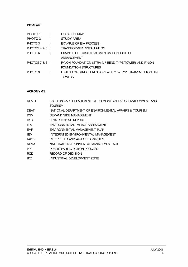
TYPE E
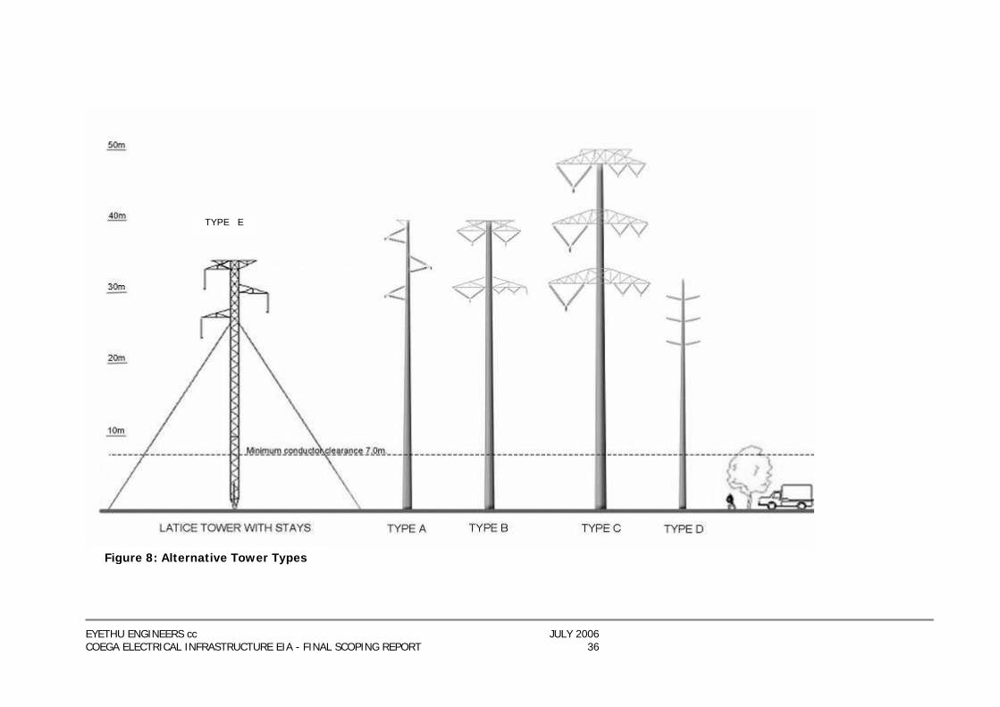
Figure 8: Alternative Tower Types
EYETHU ENGINEERS cc JULY 2006 COEGA ELECTRICAL INFRASTRUCTURE EIA - FINAL SCOPING REPORT 37
5.1.1 Tower Type A – 400kV Single-Circuit Tubular Monopole Structure This tower is intended for carrying the 400kV transmission line only. It is a tubular structure made from sheets of stainless steel and is 40metres tall. The structure is self-supporting and does not require stay cables. It is 1.0 metre in diameter at its base and is set into a concrete foundation that is 6 metres by 6 metres, (the depth of the foundation is dependant on the soil type). This tower type is preferred in sections where space is limited. It is however more costly and is considered more visually intrusive than a single pole lattice-type structure (Tower Type E). 5.1.2 Tower Type B – 400/132kV Multi-Circuit Tubular Monopole Structure This tower is intended for carrying both the 400kV transmission line and a 132kV distribution line. Two of the 400kV insulators are on the one side of the tower, whilst the other 400kV insulator and all three 132kV insulators are on the other side. Tower type B is a tubular structure made from sheets of stainless steel and is 40metres tall. The structure is self-supporting and does not require stay cables. It is 1.1 metres in diameter at its base and is set into a concrete foundation that is 6 metres by 6 metres, (the depth of the foundation is dependant on the soil type). This tower type is required where the two lines need to follow the same route in built up areas, where there is not enough space for parallel servitudes. 5.1.3 Tower Type C – 400/2X132kV Multi-Circuit Monopole Structure This tower is intended for carrying both the 400kV transmission line and two 132kV distribution lines. All three of the 400kV insulators are on the one side of the tower, whilst six 132kV insulators are on the other side of the tower. Tower type C is a tubular structure made from sheets of stainless steel and is 50 metres tall. The structure is self-supporting and does not require stay cables. It is 1.2 metres in diameter at its base and is set into a concrete foundation that is 6 metres by 6 metres, (the depth of the foundation is dependant on the soil type). This tower type is not preferred from a visual impact perspective as it is significantly taller than existing infrastructure in the study area and would constitute a high visual impact. Tower Type C is not preferred by Eskom due to the high cost of sheets of steel on a structure of this size, as well as the difficulty and high costs associated with maintenance on multicircuit structures of this size. 5.1.4 Tower Type D – 2X132kV Multi-Circuit Monopole Structure This tower is intended for carrying two 132kV distribution lines. The insulators for each 132kV line are situated evenly on either side of the tower. This tower type is a tubular structure made from sheets of stainless steel and is 32metres tall. The structure is self-supporting and does not require stay cables. It is 0.7 metres in diameter at its base and is set into a concrete foundation

EYETHU ENGINEERS cc JULY 2006 COEGA ELECTRICAL INFRASTRUCTURE EIA - FINAL SCOPING REPORT 38
that is 6 metres by 4 metres, and is 2 metres deep. It is significantly smaller than the other monopole structures relevant to this project because of the lower voltage it is designed to carry, and consequent smaller clearances and weights of the conductors.
This tower type is required where the two 132kV lines need to follow the same route. Because the distribution lines weigh less, carry lower voltages and require shorter towers than transmission lines, the tubular monopole structures do not need to be as strong as those required for supporting a 400kV transmission line. The sheets of steel that make up the tubular monopole pylons for a distribution line are made locally, whereas those needed for a transmission line need to be thicker and bigger in size, and must be imported. Thus the tubular monopole structures are preferred for the distribution section of the project, but not for the transmission section of the project. 5.1.5 Tower Type E – Single Pole Lattice Type Tower with Stays
This tower is intended for carrying the 400kV transmission line only. It is a single pole lattice type structure made from stainless steel and is 35.5 metres tall. The structure requires two stay cables that extend to 16metres away from the base of the tower on each side (i.e. the distance between the anchor points of the two stay cables is 32metres).
This tower type is preferred (for the 400kV line) to all other tower types on the project as it is considered more cost effective and is not as tall as the other types available for carrying the 400kV line. 5.1.6 Tower Type F – Strain / Bend Lattice Type Tower
This tower is used where the line needs to deviate at an angle of greater than 3 degrees, as none of the other tower types can withstand this strain. The strain or bend towers have a 10m X 10m footprint and are +35m high. An attempt will be made to minimise the use of these towers however, as they are more costly and visually-intrusive than other tower types. Figure 9 Strain / Bend tower type
EYETHU ENGINEERS cc JULY 2006 COEGA ELECTRICAL INFRASTRUCTURE EIA - FINAL SCOPING REPORT 39
5.2 PRE-CONSTRUCTION ACTIVITIES Before construction can start on a powerline or substation, Eskom needs to secure a servitude by negotiating with affected landowners. The width of a servitude is dependent on the size of a powerline as well as the land use around it. For the most part, a 400kV transmission line requires a 55 m wide servitude. A 132kV distribution line requires a 31m wide servitude. It is possible that these servitudes can overlap if they are parallel to each other. Thus approximate servitude widths for the various sections are: − Grassridge substation to Dedisa substation: 306m wide − Dedisa substation to smelter substation: 295m wide − Dedisa substation to CCGT: 426m wide A powerline servitude gives Eskom and CDC certain defined rights for the use of the specific area of land. These are: − Access to erect a powerline along a specific agreed route. − Reasonable access to operate and maintain the line inside the servitude area. − The removal of trees and vegetation that will interfere with the construction or
operation of the line. − The removal of other infrastructure that would interfere with the construction or
operation of the line, subject to negotiation with the relevant landowner. The landowner is prevented from erecting any structures or carrying out activities under the line that would interfere with the safe operation of the line. 5.3 CONSTRUCTION, OPERATION AND DECOMMISSIONING ACTIVITIES The installation of the bulk electrical infrastructure will take place in phases to coincide with the gradual development of the IDZ (i.e. infrastructure will be put in place as and when it is needed). The construction of the Dedisa substation and 400kV transmission lines between Grassridge substation, Dedisa substation and the smelter site, will however commence as soon as possible. This portion of the project will take approximately 2 years to complete. Construction of this type involves different teams working in a number of phases. There are five main teams responsible for activities such as the excavation of foundations, concrete works, erection of steel structures, stringing of cables and rehabilitation. Construction cannot take place as a single action, as there are a number of limitations with regard to certain activities (e.g. 28 days of curing for foundation concrete). The process is followed along the powerline route continuously, although some phases may occur concurrently (e.g. pegging and gate installations). However, others may occur weeks apart. All activities are required to take place within the servitude. The servitude is also utilised as an access road where possible (Coetzee, H, Eskom Transmission, Personal Communication).
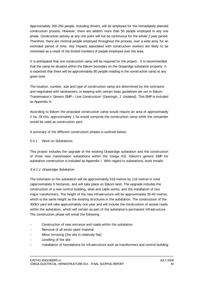
EYETHU ENGINEERS cc JULY 2006 COEGA ELECTRICAL INFRASTRUCTURE EIA - FINAL SCOPING REPORT 40
Approximately 200-250 people, including drivers, will be employed for the immediately planned construction process. However, there are seldom more than 50 people employed in any one phase. Construction activity at any one point will not be continuous for the whole 2 year period. Therefore, there are minimal people employed throughout the process, over a wide area, for an extended period of time. Any impacts associated with construction workers are likely to be minimised as a result of the limited numbers of people employed over the area. It is anticipated that one construction camp will be required for the project. It is recommended that the camp be situated within the Eskom boundary on the Grassridge substation property. It is expected that there will be approximately 80 people residing in the construction camp at any given time. The location, number, size and type of construction camp are determined by the contractor and negotiated with landowners, in keeping with certain basic guidelines set out in Eskom Transmission’s ‘Generic EMP – Line Construction’ (Geeringh, J. Undated). This EMP is included as Appendix H. According to Eskom the proposed construction camp would require an area of approximately 2 ha. Of this, approximately 1 ha would comprise the construction camp while the remainder would be used as construction yard. A summary of the different construction phases is outlined below:
5.4.1 Work on Substations
This project includes the upgrade of the existing Grassridge substation and the construction of three new transmission substations within the Coega IDZ. Eskom’s generic EMP for substation construction is included as Appendix I. With regard to substations, work entails:
5.4.1.1 Grassridge Substation The extension to the substation will be approximately 518 metres by 116 metres in total (approximately 6 hectares), and will take place on Eskom land. The upgrade includes the construction of a new control building, steel and cable works, and the installation of two major transformers. The height of the new infrastructure will be approximately 35-40 metres, which is the same height as the existing structures in the substation. The construction of the 400kV yard will take approximately one year and will include the construction of access roads within the substation, which will remain as part of the substation’s permanent infrastructure. The construction phase will entail the following: − Construction of new entrance and roads within the substation − Removal of all exotic plant material − Minor terracing (the site is relatively flat) − Levelling of the site − Installation of foundations for infrastructure such as transformers and control building
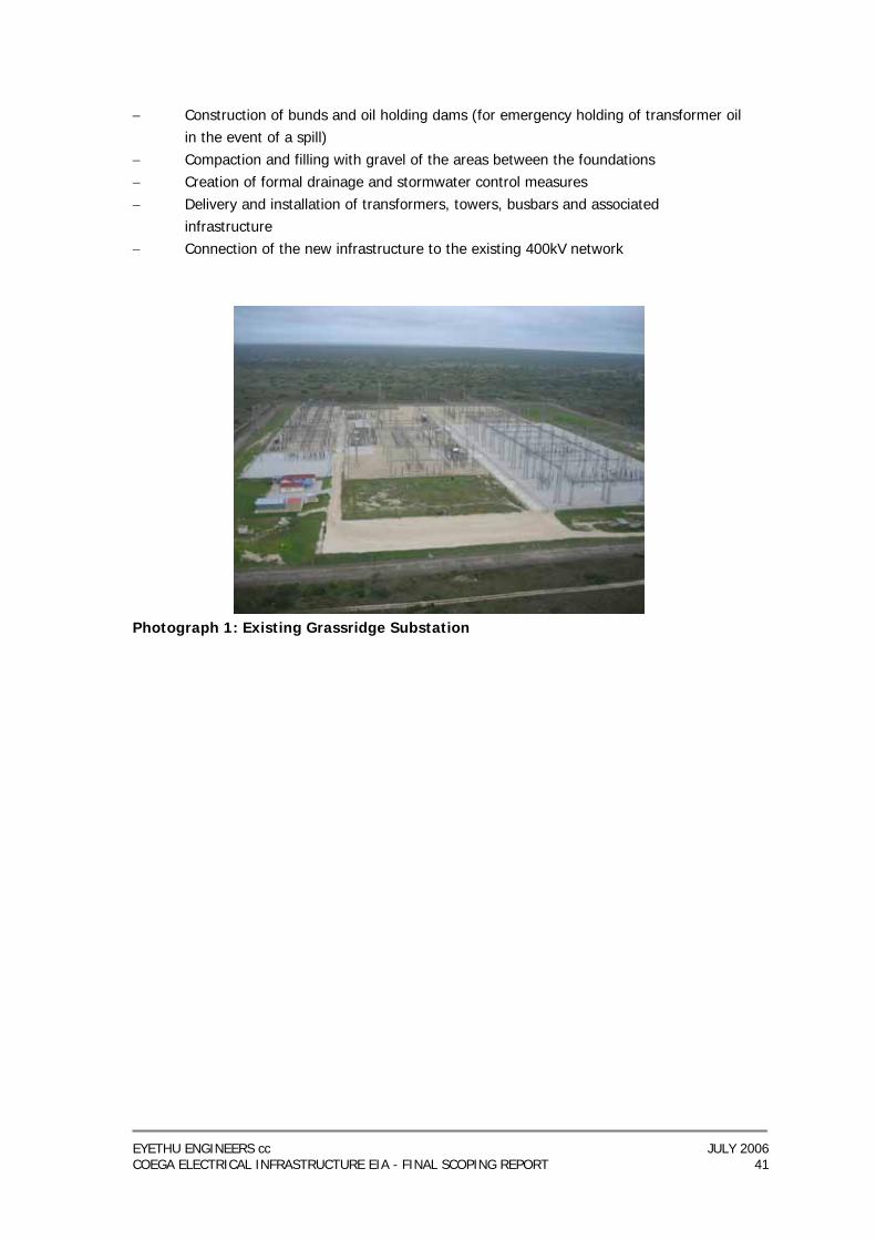
EYETHU ENGINEERS cc JULY 2006 COEGA ELECTRICAL INFRASTRUCTURE EIA - FINAL SCOPING REPORT 41
− Construction of bunds and oil holding dams (for emergency holding of transformer oil in the event of a spill)
− Compaction and filling with gravel of the areas between the foundations − Creation of formal drainage and stormwater control measures − Delivery and installation of transformers, towers, busbars and associated
infrastructure − Connection of the new infrastructure to the existing 400kV network
Photograph 1: Existing Grassridge Substation
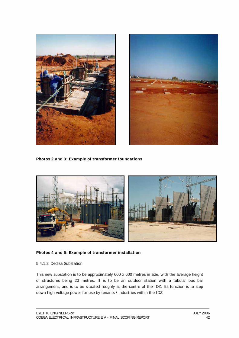
EYETHU ENGINEERS cc JULY 2006 COEGA ELECTRICAL INFRASTRUCTURE EIA - FINAL SCOPING REPORT 42
Photos 2 and 3: Example of transformer foundations
Photos 4 and 5: Example of transformer installation 5.4.1.2 Dedisa Substation This new substation is to be approximately 600 x 600 metres in size, with the average height of structures being 23 metres. It is to be an outdoor station with a tubular bus bar arrangement, and is to be situated roughly at the centre of the IDZ. Its function is to step down high voltage power for use by tenants / industries within the IDZ.
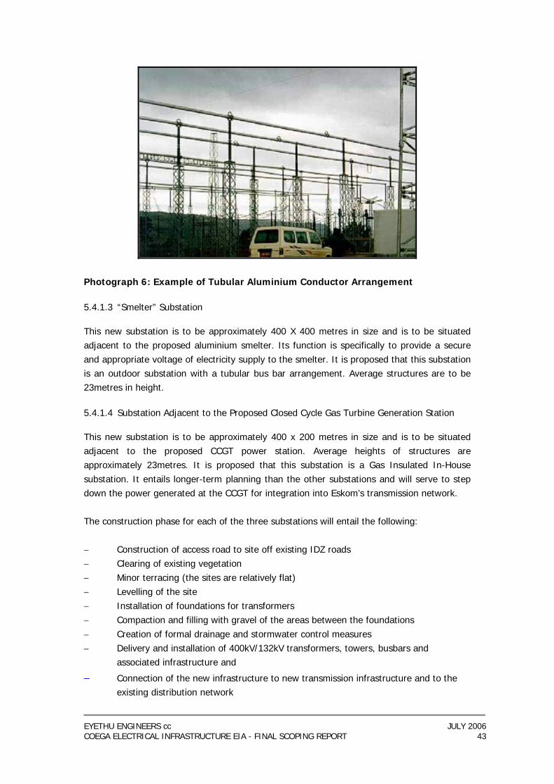
EYETHU ENGINEERS cc JULY 2006 COEGA ELECTRICAL INFRASTRUCTURE EIA - FINAL SCOPING REPORT 43
Photograph 6: Example of Tubular Aluminium Conductor Arrangement 5.4.1.3 “Smelter” Substation This new substation is to be approximately 400 X 400 metres in size and is to be situated adjacent to the proposed aluminium smelter. Its function is specifically to provide a secure and appropriate voltage of electricity supply to the smelter. It is proposed that this substation is an outdoor substation with a tubular bus bar arrangement. Average structures are to be 23metres in height. 5.4.1.4 Substation Adjacent to the Proposed Closed Cycle Gas Turbine Generation Station This new substation is to be approximately 400 x 200 metres in size and is to be situated adjacent to the proposed CCGT power station. Average heights of structures are approximately 23metres. It is proposed that this substation is a Gas Insulated In-House substation. It entails longer-term planning than the other substations and will serve to step down the power generated at the CCGT for integration into Eskom’s transmission network. The construction phase for each of the three substations will entail the following: − Construction of access road to site off existing IDZ roads − Clearing of existing vegetation − Minor terracing (the sites are relatively flat) − Levelling of the site − Installation of foundations for transformers − Compaction and filling with gravel of the areas between the foundations − Creation of formal drainage and stormwater control measures − Delivery and installation of 400kV/132kV transformers, towers, busbars and
associated infrastructure and
− Connection of the new infrastructure to new transmission infrastructure and to the existing distribution network
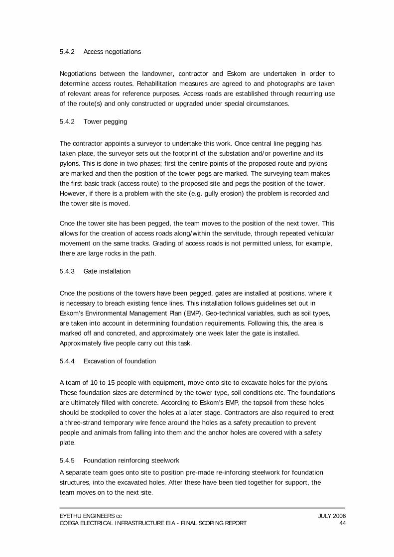
EYETHU ENGINEERS cc JULY 2006 COEGA ELECTRICAL INFRASTRUCTURE EIA - FINAL SCOPING REPORT 44
5.4.2 Access negotiations
Negotiations between the landowner, contractor and Eskom are undertaken in order to determine access routes. Rehabilitation measures are agreed to and photographs are taken of relevant areas for reference purposes. Access roads are established through recurring use of the route(s) and only constructed or upgraded under special circumstances.
5.4.2 Tower pegging
The contractor appoints a surveyor to undertake this work. Once central line pegging has taken place, the surveyor sets out the footprint of the substation and/or powerline and its pylons. This is done in two phases; first the centre points of the proposed route and pylons are marked and then the position of the tower pegs are marked. The surveying team makes the first basic track (access route) to the proposed site and pegs the position of the tower. However, if there is a problem with the site (e.g. gully erosion) the problem is recorded and the tower site is moved. Once the tower site has been pegged, the team moves to the position of the next tower. This allows for the creation of access roads along/within the servitude, through repeated vehicular movement on the same tracks. Grading of access roads is not permitted unless, for example, there are large rocks in the path.
5.4.3 Gate installation
Once the positions of the towers have been pegged, gates are installed at positions, where it is necessary to breach existing fence lines. This installation follows guidelines set out in Eskom’s Environmental Management Plan (EMP). Geo-technical variables, such as soil types, are taken into account in determining foundation requirements. Following this, the area is marked off and concreted, and approximately one week later the gate is installed. Approximately five people carry out this task.
5.4.4 Excavation of foundation
A team of 10 to 15 people with equipment, move onto site to excavate holes for the pylons. These foundation sizes are determined by the tower type, soil conditions etc. The foundations are ultimately filled with concrete. According to Eskom’s EMP, the topsoil from these holes should be stockpiled to cover the holes at a later stage. Contractors are also required to erect a three-strand temporary wire fence around the holes as a safety precaution to prevent people and animals from falling into them and the anchor holes are covered with a safety plate.
5.4.5 Foundation reinforcing steelwork
A separate team goes onto site to position pre-made re-inforcing steelwork for foundation structures, into the excavated holes. After these have been tied together for support, the team moves on to the next site.
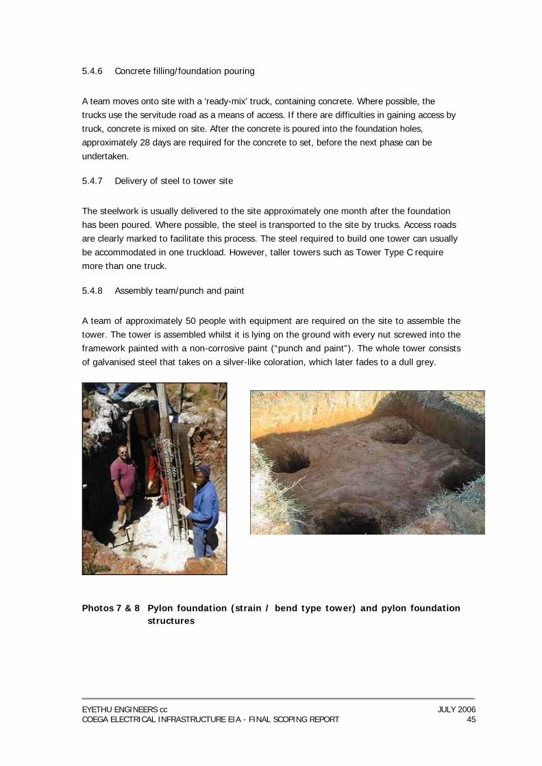
EYETHU ENGINEERS cc JULY 2006 COEGA ELECTRICAL INFRASTRUCTURE EIA - FINAL SCOPING REPORT 45
5.4.6 Concrete filling/foundation pouring
A team moves onto site with a ‘ready-mix’ truck, containing concrete. Where possible, the trucks use the servitude road as a means of access. If there are difficulties in gaining access by truck, concrete is mixed on site. After the concrete is poured into the foundation holes, approximately 28 days are required for the concrete to set, before the next phase can be undertaken.
5.4.7 Delivery of steel to tower site
The steelwork is usually delivered to the site approximately one month after the foundation has been poured. Where possible, the steel is transported to the site by trucks. Access roads are clearly marked to facilitate this process. The steel required to build one tower can usually be accommodated in one truckload. However, taller towers such as Tower Type C require more than one truck.
5.4.8 Assembly team/punch and paint
A team of approximately 50 people with equipment are required on the site to assemble the tower. The tower is assembled whilst it is lying on the ground with every nut screwed into the framework painted with a non-corrosive paint (“punch and paint”). The whole tower consists of galvanised steel that takes on a silver-like coloration, which later fades to a dull grey.
Photos 7 & 8 Pylon foundation (strain / bend type tower) and pylon foundation
structures
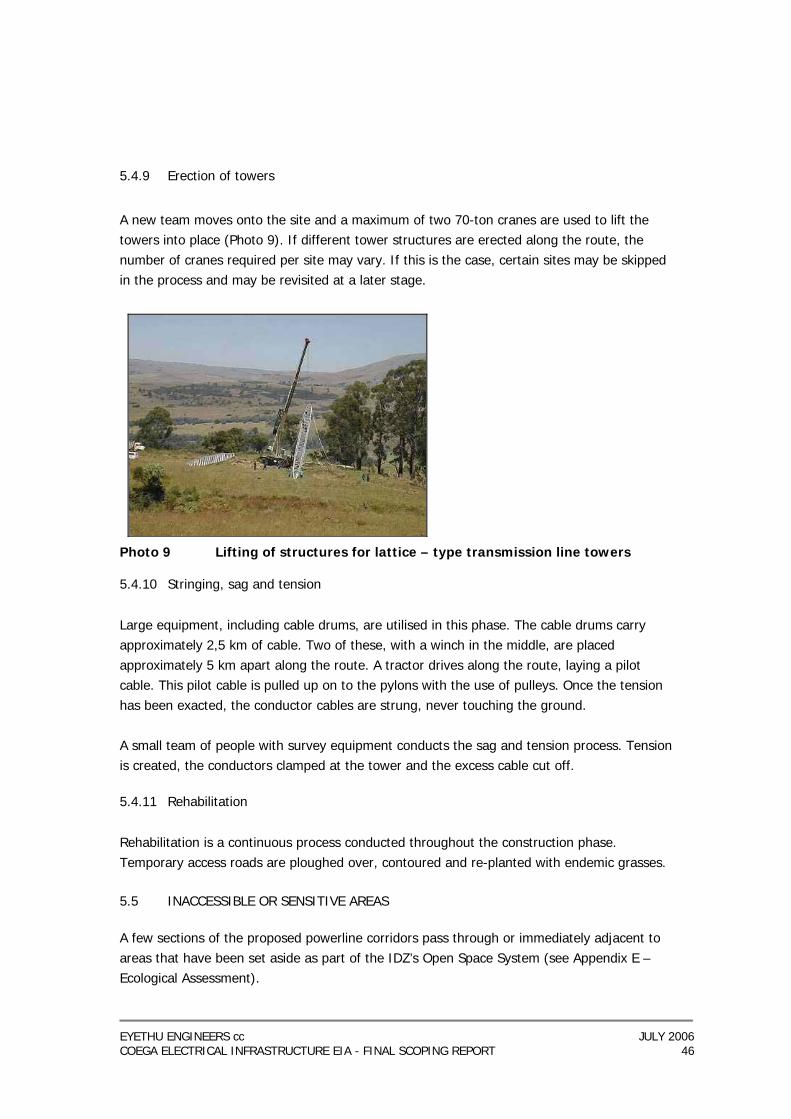
EYETHU ENGINEERS cc JULY 2006 COEGA ELECTRICAL INFRASTRUCTURE EIA - FINAL SCOPING REPORT 46
5.4.9 Erection of towers
A new team moves onto the site and a maximum of two 70-ton cranes are used to lift the towers into place (Photo 9). If different tower structures are erected along the route, the number of cranes required per site may vary. If this is the case, certain sites may be skipped in the process and may be revisited at a later stage.
Photo 9 Lifting of structures for lattice – type transmission line towers
5.4.10 Stringing, sag and tension
Large equipment, including cable drums, are utilised in this phase. The cable drums carry approximately 2,5 km of cable. Two of these, with a winch in the middle, are placed approximately 5 km apart along the route. A tractor drives along the route, laying a pilot cable. This pilot cable is pulled up on to the pylons with the use of pulleys. Once the tension has been exacted, the conductor cables are strung, never touching the ground. A small team of people with survey equipment conducts the sag and tension process. Tension is created, the conductors clamped at the tower and the excess cable cut off.
5.4.11 Rehabilitation
Rehabilitation is a continuous process conducted throughout the construction phase. Temporary access roads are ploughed over, contoured and re-planted with endemic grasses. 5.5 INACCESSIBLE OR SENSITIVE AREAS A few sections of the proposed powerline corridors pass through or immediately adjacent to areas that have been set aside as part of the IDZ’s Open Space System (see Appendix E – Ecological Assessment).
EYETHU ENGINEERS cc JULY 2006 COEGA ELECTRICAL INFRASTRUCTURE EIA - FINAL SCOPING REPORT 47
It is recommended that the existing access routes are used wherever possible and that specialist ecologists play a part in the development of the project-specific Environmental Management Plan to ensure that sensitive fauna and flora are protected. It is further recommended that the number of pylons placed in these sensitive areas is minimised wherever possible. 5.6 OPERATION AND MAINTENANCE During operations, Eskom requires access to the servitude to enable maintenance of the powerline. This could require traversing private property. Maintenance is carried out at regular intervals and is sometimes done by helicopter so that electricity supplies are not disrupted. Maintenance activities are highly specialised and are, therefore, carried out by Eskom employees. The servitude will need to be cleared occasionally to ensure that vegetation does not interfere with the operation of the line. This entails the cutting back of vegetation and not the clearing of the roots. It is understood from the specialist ecological study that the corridor will provide an important refuge for several species of fauna and flora and thus activities within the powerline will be minimised wherever possible. 5.7 DECOMMISSIONING It is very rare that powerlines are decommissioned as their need and justification has been carefully established by Eskom’s planning unit. However, should the need to decommission one of the powerlines during its operational life, the following is to be assumed: − The physical removal of the line and the pylons would entail the reversal of the
construction process; − A rehabilitation programme would need to be agreed to with the landowner before
being implemented; − The disposal of materials from the decommissioned powerline (steel / cabling /
concrete etc) would either need to be recycled or disposed of at an approved waste disposal facility and
− Specific considerations regarding the servitude and landowner rights would need to be negotiated with the landowner at the time of decommissioning and fall outside the scope of this EIA.
5.8 DESIGN LIMITATIONS AND PHYSICAL PARAMETERS REQUIRED FOR THE POWERLINES Although some aspects of the powerline alignment can be negotiated or changed due to the presence of environmental limitations, there are certain parameters that are unavoidable and must be taken into account. These include:
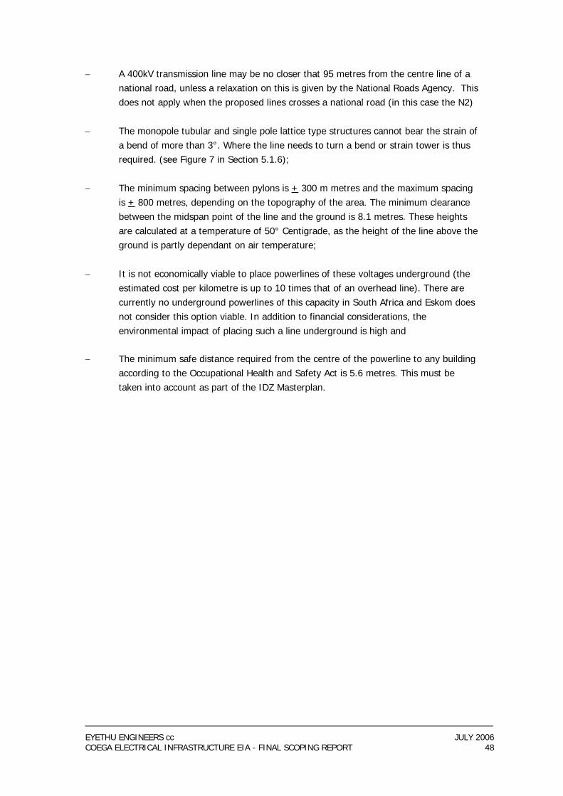
EYETHU ENGINEERS cc JULY 2006 COEGA ELECTRICAL INFRASTRUCTURE EIA - FINAL SCOPING REPORT 48
− A 400kV transmission line may be no closer that 95 metres from the centre line of a national road, unless a relaxation on this is given by the National Roads Agency. This does not apply when the proposed lines crosses a national road (in this case the N2)
− The monopole tubular and single pole lattice type structures cannot bear the strain of
a bend of more than 3°. Where the line needs to turn a bend or strain tower is thus required. (see Figure 7 in Section 5.1.6);
− The minimum spacing between pylons is + 300 m metres and the maximum spacing
is + 800 metres, depending on the topography of the area. The minimum clearance between the midspan point of the line and the ground is 8.1 metres. These heights are calculated at a temperature of 50° Centigrade, as the height of the line above the ground is partly dependant on air temperature;
− It is not economically viable to place powerlines of these voltages underground (the
estimated cost per kilometre is up to 10 times that of an overhead line). There are currently no underground powerlines of this capacity in South Africa and Eskom does not consider this option viable. In addition to financial considerations, the environmental impact of placing such a line underground is high and
− The minimum safe distance required from the centre of the powerline to any building
according to the Occupational Health and Safety Act is 5.6 metres. This must be taken into account as part of the IDZ Masterplan.

EYETHU ENGINEERS cc JULY 2006 COEGA ELECTRICAL INFRASTRUCTURE EIA - FINAL SCOPING REPORT 49
CHAPTER 7: PROJECT ALTERNATIVES 7.1 INTRODUCTION One of the functions of the environmental scoping process is to describe and evaluate the alternatives to the project. A limited choice of powerline corridors and substation sites exist within the Coega IDZ in line with the Coega IDZ masterplan that outlines specific zones, open spaces, and utility corridors. The required power infrastructure needs to fit into this framework that limits alternative corridors that can be assessed within the Coega IDZ. Other types of alternatives i.e. the “no go” option, and pylon design alternatives still exist and are examined below. − Strategic Alternatives (Including the “No Go” Alternative) − Alternative designs for the proposed powerlines (as discussed in Chapter 5) and − Alternative designs for the proposed substations 7.2 STRATEGIC ALTERNATIVES TO THE INSTALLATION OF BULK ELECTRICAL INFRASTRUCTURE WITHIN THE COEGA IDZ Strategic alternatives to the bulk electrical infrastructure project are limited to the “do nothing” option, as there is only one way of integrating the electricity needs of the IDZ, i.e. through the construction of powerlines and substations. Demand side management is also discussed although it is shown not to be a viable alternative. 7.2.1 The “Do Nothing” Option The Department of Environmental Affairs and Tourism states that the “do nothing” or “no-go” option should be considered in cases where the proposed development could have significant negative impacts. For this project, the no-development option would mean not undertaking the proposed installation of bulk electrical infrastructure within the IDZ. This does not appear to be a viable option as this would essentially prevent the IDZ from developing. Environmental and economic studies have shown the benefits of the IDZ to the immediate area and the Eastern Cape region. For the IDZ to be viable and play a role in South Africa’s economy, the proposed electrical infrastructure is required in the form as stated by this project. The “No Go” option is not regarded as a viable alternative. 7.2.2 Demand-side Management Demand Side Management (DSM) is a function carried out by the electricity supply utility aimed at encouraging a reduction in the amount of electricity used at peak times. This is achieved by influencing customer usage to improve efficiency and reduce overall demand. These efforts are intended to produce a flat load duration curve to ensure the most efficient use of installed network capacity. By reducing peak demand and shifting load from high load to low load periods, reductions in capital expenditure (for network capacity expansion) and operating costs can be achieved. One of the basic tools is the price differentiation (such as time of use tariffs) between peak demand time and low demand time. This option is practiced to a certain extent, but is

EYETHU ENGINEERS cc JULY 2006 COEGA ELECTRICAL INFRASTRUCTURE EIA - FINAL SCOPING REPORT 50
currently not considered feasible for managing the level of growth forecast for the Eastern Cape region. The existing power network will not be able to supply the IDZ and cannot be modified to integrate IDZ components into the network. Instead, new bulk infrastructure is required, as proposed in this project. 7.3 DESIGN ALTERNATIVES Design alternatives take the form of various tower and line configurations for the power line component of the project and different layout designs for the substation component of the project. Both aspects have been carefully considered by Eskom Transmission and the Coega Development Corporation to ensure that the most functional and cost effective options are chosen. 7.3.1 Placing the Transmission Line Underground The environmental impacts associated with placing a high voltage powerline underground are significantly higher than the conventional aboveground structures. In addition the space required is that equivalent to a 4 lane highway as the conductors cannot be cooled by the air and need to be spaced apart. It is not economically viable to place a transmission line of this voltage underground - the estimated cost per kilometre is up to 10 times that of an overhead line. 7.3.2 Alternative Pylon Options The various pylon options were discussed in Chapter 5. The self-supporting tower types are considered the most cost effective and suitable in this scenario. Other towers are often designed to be used where space constraints or visual impacts are sensitive. However, in an industrialised setting of this nature, with pre-planned space available in the form of a utility corridor, the self supporting tower is regarded as both the most practical and cost-effective. 7.3.3 Substation Design Alternatives Careful cost benefit and planning analyses have been undertaken by Eskom Transmission to ensure that the most cost effective and efficient substations are designed for the IDZ. Both the Dedisa and Smelter substations are to be outdoor substation with a tubular bus bar arrangement. This is significantly cheaper than constructing a Gas Insulted Substation. The substation at the CCGT site needs to be a GIS due to its proximity to the coast and associated damage from salt corrosion. The current proposed designs are regarded as the best alternatives available in terms of substation design.
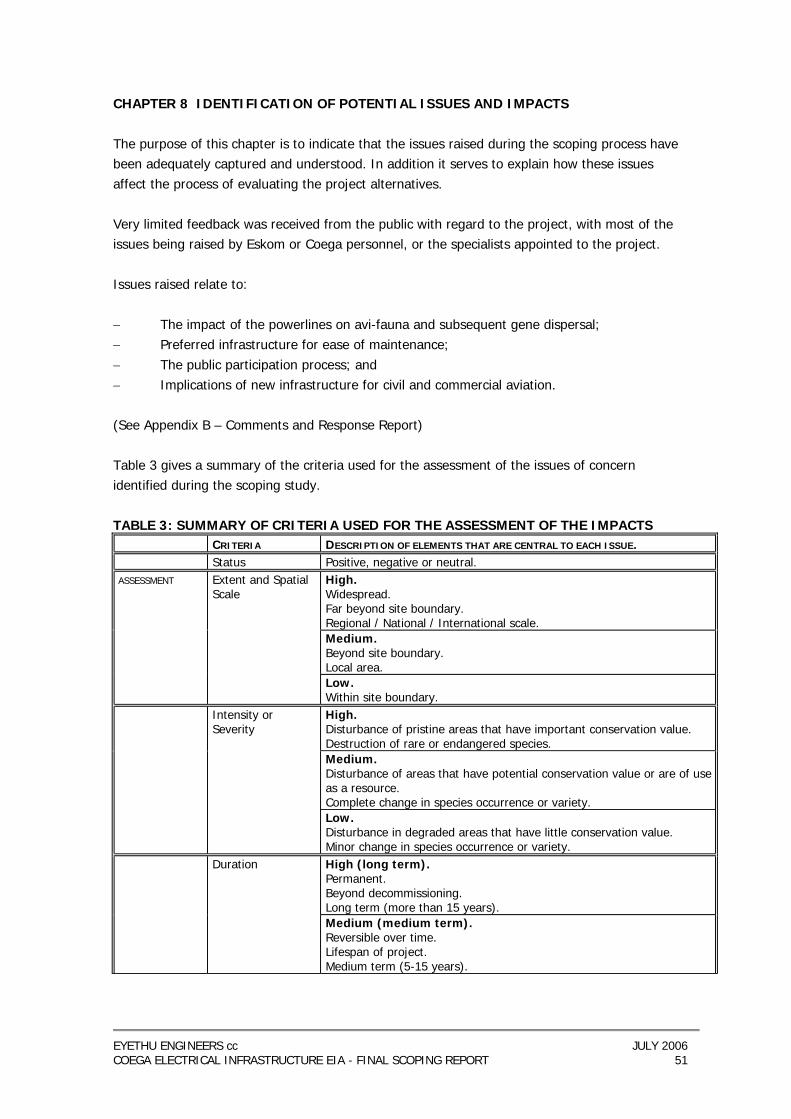
EYETHU ENGINEERS cc JULY 2006 COEGA ELECTRICAL INFRASTRUCTURE EIA - FINAL SCOPING REPORT 51
CHAPTER 8 IDENTIFICATION OF POTENTIAL ISSUES AND IMPACTS The purpose of this chapter is to indicate that the issues raised during the scoping process have been adequately captured and understood. In addition it serves to explain how these issues affect the process of evaluating the project alternatives. Very limited feedback was received from the public with regard to the project, with most of the issues being raised by Eskom or Coega personnel, or the specialists appointed to the project. Issues raised relate to: − The impact of the powerlines on avi-fauna and subsequent gene dispersal; − Preferred infrastructure for ease of maintenance; − The public participation process; and − Implications of new infrastructure for civil and commercial aviation. (See Appendix B – Comments and Response Report) Table 3 gives a summary of the criteria used for the assessment of the issues of concern identified during the scoping study. TABLE 3: SUMMARY OF CRITERIA USED FOR THE ASSESSMENT OF THE IMPACTS CRITERIA DESCRIPTION OF ELEMENTS THAT ARE CENTRAL TO EACH ISSUE. Status Positive, negative or neutral. ASSESSMENT Extent and Spatial
Scale High. Widespread. Far beyond site boundary. Regional / National / International scale.
Medium. Beyond site boundary. Local area.
Low. Within site boundary.
Intensity or Severity
High. Disturbance of pristine areas that have important conservation value. Destruction of rare or endangered species.
Medium. Disturbance of areas that have potential conservation value or are of use as a resource. Complete change in species occurrence or variety.
Low. Disturbance in degraded areas that have little conservation value. Minor change in species occurrence or variety.
Duration High (long term). Permanent. Beyond decommissioning. Long term (more than 15 years).
Medium (medium term). Reversible over time. Lifespan of project. Medium term (5-15 years).
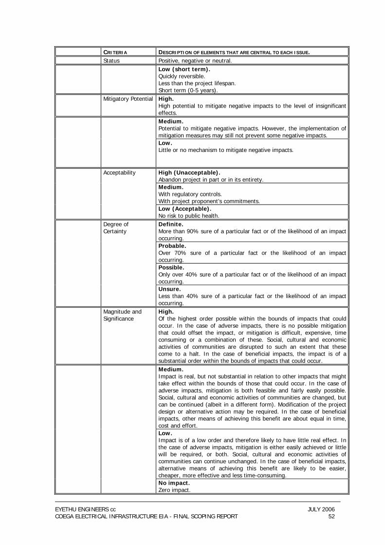
EYETHU ENGINEERS cc JULY 2006 COEGA ELECTRICAL INFRASTRUCTURE EIA - FINAL SCOPING REPORT 52
CRITERIA DESCRIPTION OF ELEMENTS THAT ARE CENTRAL TO EACH ISSUE. Status Positive, negative or neutral. Low (short term).
Quickly reversible. Less than the project lifespan. Short term (0-5 years).
Mitigatory Potential High. High potential to mitigate negative impacts to the level of insignificant effects.
Medium. Potential to mitigate negative impacts. However, the implementation of mitigation measures may still not prevent some negative impacts.
Low. Little or no mechanism to mitigate negative impacts.
Acceptability High (Unacceptable). Abandon project in part or in its entirety.
Medium. With regulatory controls. With project proponent’s commitments.
Low (Acceptable). No risk to public health.
Degree of Certainty
Definite. More than 90% sure of a particular fact or of the likelihood of an impact occurring.
Probable. Over 70% sure of a particular fact or the likelihood of an impact occurring.
Possible. Only over 40% sure of a particular fact or of the likelihood of an impact occurring.
Unsure. Less than 40% sure of a particular fact or the likelihood of an impact occurring.
Magnitude and Significance
High. Of the highest order possible within the bounds of impacts that could occur. In the case of adverse impacts, there is no possible mitigation that could offset the impact, or mitigation is difficult, expensive, time consuming or a combination of these. Social, cultural and economic activities of communities are disrupted to such an extent that these come to a halt. In the case of beneficial impacts, the impact is of a substantial order within the bounds of impacts that could occur.
Medium. Impact is real, but not substantial in relation to other impacts that might take effect within the bounds of those that could occur. In the case of adverse impacts, mitigation is both feasible and fairly easily possible. Social, cultural and economic activities of communities are changed, but can be continued (albeit in a different form). Modification of the project design or alternative action may be required. In the case of beneficial impacts, other means of achieving this benefit are about equal in time, cost and effort.
Low. Impact is of a low order and therefore likely to have little real effect. In the case of adverse impacts, mitigation is either easily achieved or little will be required, or both. Social, cultural and economic activities of communities can continue unchanged. In the case of beneficial impacts, alternative means of achieving this benefit are likely to be easier, cheaper, more effective and less time-consuming.
No impact. Zero impact.
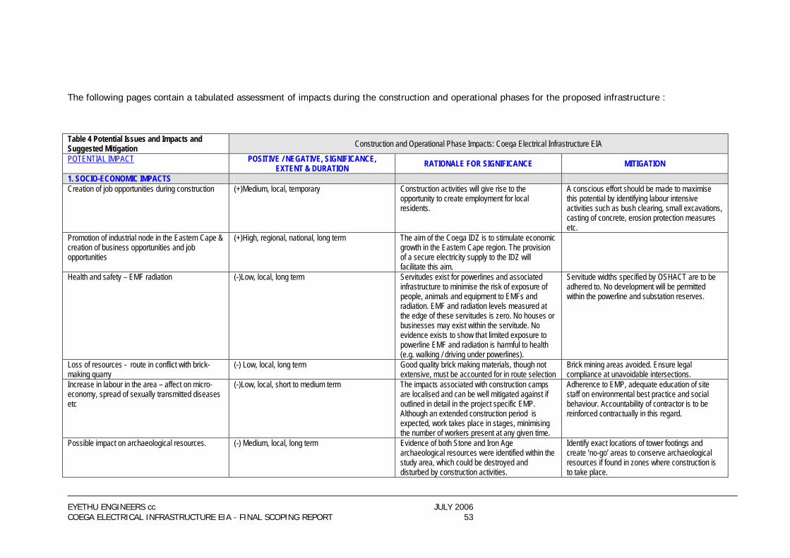
EYETHU ENGINEERS cc JULY 2006 COEGA ELECTRICAL INFRASTRUCTURE EIA - FINAL SCOPING REPORT 53
The following pages contain a tabulated assessment of impacts during the construction and operational phases for the proposed infrastructure : Table 4 Potential Issues and Impacts and Suggested Mitigation Construction and Operational Phase Impacts: Coega Electrical Infrastructure EIA
POTENTIAL IMPACT POSITIVE / NEGATIVE, SIGNIFICANCE, EXTENT & DURATION RATIONALE FOR SIGNIFICANCE MITIGATION
1. SOCIO-ECONOMIC IMPACTS Creation of job opportunities during construction (+)Medium, local, temporary Construction activities will give rise to the
opportunity to create employment for local residents.
A conscious effort should be made to maximise this potential by identifying labour intensive activities such as bush clearing, small excavations, casting of concrete, erosion protection measures etc.
Promotion of industrial node in the Eastern Cape & creation of business opportunities and job opportunities
(+)High, regional, national, long term The aim of the Coega IDZ is to stimulate economic growth in the Eastern Cape region. The provision of a secure electricity supply to the IDZ will facilitate this aim.
Health and safety – EMF radiation (-)Low, local, long term Servitudes exist for powerlines and associated infrastructure to minimise the risk of exposure of people, animals and equipment to EMFs and radiation. EMF and radiation levels measured at the edge of these servitudes is zero. No houses or businesses may exist within the servitude. No evidence exists to show that limited exposure to powerline EMF and radiation is harmful to health (e.g. walking / driving under powerlines).
Servitude widths specified by OSHACT are to be adhered to. No development will be permitted within the powerline and substation reserves.
Loss of resources - route in conflict with brick-making quarry
(-) Low, local, long term Good quality brick making materials, though not extensive, must be accounted for in route selection
Brick mining areas avoided. Ensure legal compliance at unavoidable intersections.
Increase in labour in the area – affect on micro-economy, spread of sexually transmitted diseases etc
(-)Low, local, short to medium term The impacts associated with construction camps are localised and can be well mitigated against if outlined in detail in the project specific EMP. Although an extended construction period is expected, work takes place in stages, minimising the number of workers present at any given time.
Adherence to EMP, adequate education of site staff on environmental best practice and social behaviour. Accountability of contractor is to be reinforced contractually in this regard.
Possible impact on archaeological resources. (-) Medium, local, long term Evidence of both Stone and Iron Age archaeological resources were identified within the study area, which could be destroyed and disturbed by construction activities.
Identify exact locations of tower footings and create ‘no-go’ areas to conserve archaeological resources if found in zones where construction is to take place.
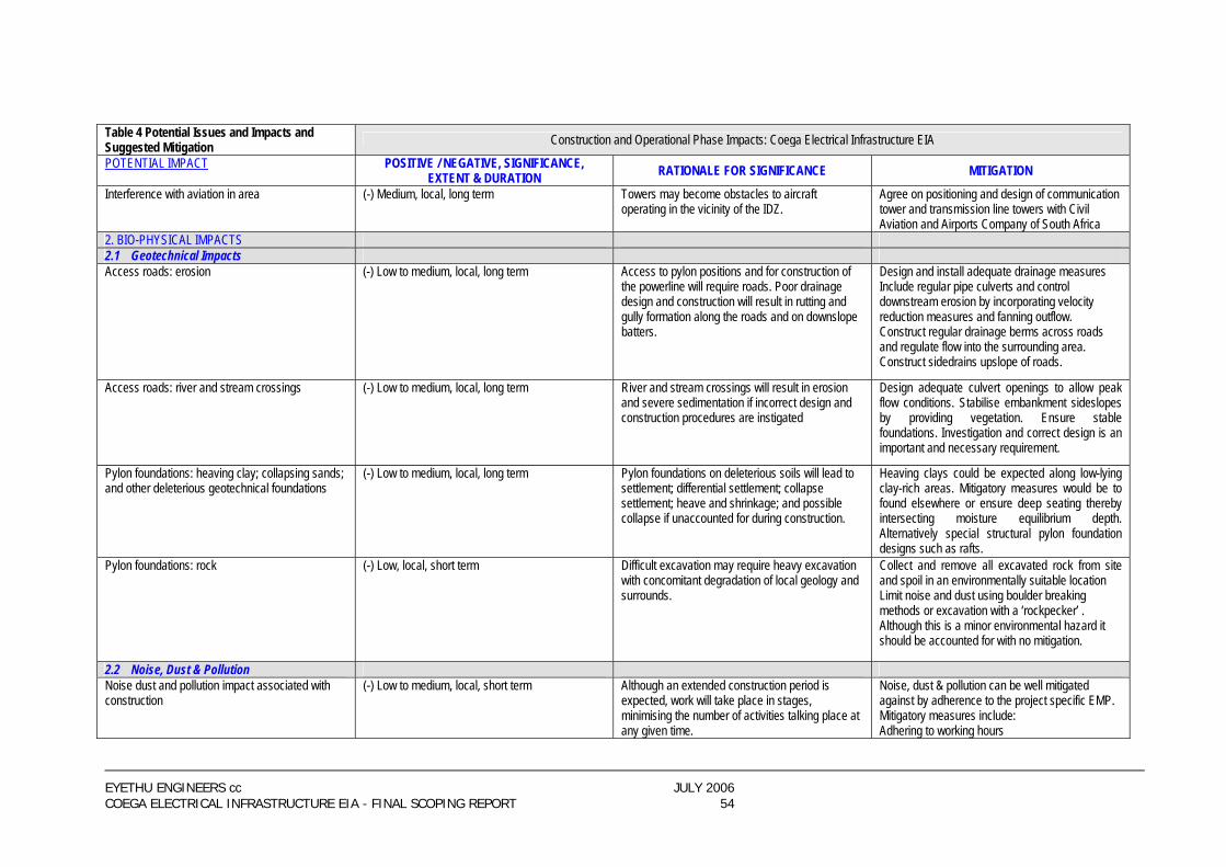
EYETHU ENGINEERS cc JULY 2006 COEGA ELECTRICAL INFRASTRUCTURE EIA - FINAL SCOPING REPORT 54
Table 4 Potential Issues and Impacts and Suggested Mitigation Construction and Operational Phase Impacts: Coega Electrical Infrastructure EIA
POTENTIAL IMPACT POSITIVE / NEGATIVE, SIGNIFICANCE, EXTENT & DURATION RATIONALE FOR SIGNIFICANCE MITIGATION
Interference with aviation in area (-) Medium, local, long term Towers may become obstacles to aircraft operating in the vicinity of the IDZ.
Agree on positioning and design of communication tower and transmission line towers with Civil Aviation and Airports Company of South Africa
2. BIO-PHYSICAL IMPACTS 2.1 Geotechnical Impacts Access roads: erosion (-) Low to medium, local, long term Access to pylon positions and for construction of
the powerline will require roads. Poor drainage design and construction will result in rutting and gully formation along the roads and on downslope batters.
Design and install adequate drainage measures Include regular pipe culverts and control downstream erosion by incorporating velocity reduction measures and fanning outflow. Construct regular drainage berms across roads and regulate flow into the surrounding area. Construct sidedrains upslope of roads.
Access roads: river and stream crossings (-) Low to medium, local, long term River and stream crossings will result in erosion and severe sedimentation if incorrect design and construction procedures are instigated
Design adequate culvert openings to allow peak flow conditions. Stabilise embankment sideslopes by providing vegetation. Ensure stable foundations. Investigation and correct design is an important and necessary requirement.
Pylon foundations: heaving clay; collapsing sands; and other deleterious geotechnical foundations
(-) Low to medium, local, long term Pylon foundations on deleterious soils will lead to settlement; differential settlement; collapse settlement; heave and shrinkage; and possible collapse if unaccounted for during construction.
Heaving clays could be expected along low-lying clay-rich areas. Mitigatory measures would be to found elsewhere or ensure deep seating thereby intersecting moisture equilibrium depth. Alternatively special structural pylon foundation designs such as rafts.
Pylon foundations: rock
(-) Low, local, short term Difficult excavation may require heavy excavation with concomitant degradation of local geology and surrounds.
Collect and remove all excavated rock from site and spoil in an environmentally suitable location Limit noise and dust using boulder breaking methods or excavation with a ‘rockpecker’ . Although this is a minor environmental hazard it should be accounted for with no mitigation.
2.2 Noise, Dust & Pollution Noise dust and pollution impact associated with construction
(-) Low to medium, local, short term Although an extended construction period is expected, work will take place in stages, minimising the number of activities talking place at any given time.
Noise, dust & pollution can be well mitigated against by adherence to the project specific EMP. Mitigatory measures include: Adhering to working hours

EYETHU ENGINEERS cc JULY 2006 COEGA ELECTRICAL INFRASTRUCTURE EIA - FINAL SCOPING REPORT 55
Table 4 Potential Issues and Impacts and Suggested Mitigation Construction and Operational Phase Impacts: Coega Electrical Infrastructure EIA
POTENTIAL IMPACT POSITIVE / NEGATIVE, SIGNIFICANCE, EXTENT & DURATION RATIONALE FOR SIGNIFICANCE MITIGATION
The use of silencers on vehicles and equipment Watering haul and access roads.
Pollution resulting from transformer failure at substation
(-) Low, local, short term All transformers are bunded with oil traps/sumps in the event of catastrophic failure. Bunds are sized to contain all oils that may be spillrd.
2.3 Impacts on Ecology (excl Avi Fauna) Habitat fragmentation as a result of the loss of vegetation cover
(-) Low, local, medium term to permanent Land clearing leads to loss of habitat and exposure of land to the elements, which may result in associated local or downstream degradation.
Keep removal of vegetation to a minimum.
Loss of indigenous habitat for indigenous fauna (-) Low, local, medium to long term Existing access paths are to be used wherever possible, and the amount of vegetation to be cleared is only that of the actual pylon base. Construction camps are to be situated on already-transformed areas.
Loss of vegetation cover implies a loss of habitat. Keep the removal of vegetation to a minimum.
Reduction in the quantity of carbon stored in vegetation.
(-) Low, local, short term AS per the EMP, any topsoil that is moved is to be stockpiled for return to the site after construction, thus retaining seeds for later germination.
The removal of vegetation and plant biomass will lead to a decrease in the amount of fixed carbon in the tower footprints and the corridor underneath the conductors. Keep the removal of vegetation to a minimum.
Increase in soil erosion as a result of the loss of vegetation cover
(-) Low, local, medium term Existing access tracks are to be used wherever possible, erosion control measures are to be covered in the EMP.
Ensure that the loss in vegetation cover is kept to a minimum. Disturbed areas should be rehabilitated as soon as possible.
Harvesting of fuelwood (-) Low, local, short term This is dependant on the time that poles etc are stored, as the vegetation should be able to recover if the storage is short term.
Discourage the harvesting of fuelwood by workers through a briefing session with the site foreman or the workers themselves.
Hunting of indigenous local fauna (-) Low, local, short term There are a number of endemic and endangered species in the area in question, which may be encountered during construction activities.
Construction workers should be informed that hunting of wild animals will not be allowed under the future Eastern Cape Environmental Conservation Act (now Bill). Any acts of this nature should be discouraged.
Barrier to gene dispersal (-) Medium to low, local , long term Alien vegetation is an ecological threat to on existing indigenous vegetation and needs to be eradicated to prevent further encroachment.
Fragmentation of habitat through the removal of vegetation cover may make it difficult for some plants to disperse effectively. The developers should ensure that the removal of vegetation is kept to a minimum

EYETHU ENGINEERS cc JULY 2006 COEGA ELECTRICAL INFRASTRUCTURE EIA - FINAL SCOPING REPORT 56
Table 4 Potential Issues and Impacts and Suggested Mitigation Construction and Operational Phase Impacts: Coega Electrical Infrastructure EIA
POTENTIAL IMPACT POSITIVE / NEGATIVE, SIGNIFICANCE, EXTENT & DURATION RATIONALE FOR SIGNIFICANCE MITIGATION
Impact of night lights on fauna in study area associated with substations
(-) Low, local, long term Insects attracted to lighting are expected to attract foraging bats and other fauna.
Lights are to be designed to reduce “light pollution” by utilising downlighters. Substations will be in heavily developed areas, which will offer little habitat for indigenous fauna.
2.4 Impacts on Avi-Fauna (Birds) Destruction and disturbance of bird habitats and riparian areas
(-) Low, local, short term Damara Tern and African Black Oystercatcher in dune areas. Half-collared Kingfisher in riparian or riverine areas.
Construction and maintenance of the overhead lines and the Power Station Substation will result in disturbance of avifauna. It is recommended that the dune fields area be avoided, although it will not be possible. It is recommended that all construction and maintenance activities be undertaken in conformance with generally accepted environmental best practice guidelines, in order to minimize the impact on avifauna. Activities such as driving and earth moving in the dune area should be kept to a minimum. This applies to the riparian areas.
Impact on quality of electricity supply due to faulting caused by birds
(-) Medium, regional, long term Birds roost and use tower structures for hunting, which may sometimes have adverse effects on operations.
When the tower structures for the lines are finalized, EWT will need to examine the technical drawings and determine whether faulting due to birds is likely. If it is to be a problem, EWT will provide recommendations on how to mitigate.
Habitat destruction (-) Low, local, long term Damara Tern and African Black Oystercatcher in dune areas
Construction and maintenance of the overhead lines and the Power Station Substation will result in disturbance of avifauna in the dune fields, and to an extent in riparian areas. It is recommended that if possible the dune fields area be avoided, although if the Gas Power Station is situated right on the coast, it will not be possible. Failing, it is recommended that construction and maintenance be undertaken in conformance with accepted environmental best practice guidelines, in order to minimize the impact on avifauna. Activities such as driving and earth moving in the dune area should be kept to an absolute minimum. These last two points would apply to the riparian areas as well.
EYETHU ENGINEERS cc JULY 2006 COEGA ELECTRICAL INFRASTRUCTURE EIA - FINAL SCOPING REPORT 57
CHAPTER 9 CONCLUSIONS AND RECOMMENDATIONS It is the finding of this report that a definite need has been established for the installation of bulk electrical infrastructure within the Coega IDZ. The specialist scoping studies commissioned as part of this study have provided useful input into the environmental impact process. Findings and recommendations of these reports, together with feedback from the public obtained during the public participation process, have allowed the following conclusions and recommendations:
− The construction of the proposed infrastructure within the IDZ will have a significant environmental impact on the receiving environment, however this must be seen in the context that it is all contained within the proposed (IDZ), which will ultimately be heavily industrialised and modified.
− The benefits that the proposed electricity infrastructure offer are of great regional and national significance and far outweigh the negative, predominantly local and mitigatable impacts.
− The proposed infrastructure is inherently necessary to enable the IDZ to function as envisaged and to attract the level of development necessary to make it viable.
− The proposed transmission line route should be followed as shown in the project description as this route appears to be the best option in terms of utilisation of existing servitudes, grouping infrastructure into “utility corridors”, and avoiding riparian buffer zones and sensitive areas of vegetation.
− The tower type options and detailed routes as described in detail in Chapter 6 are recommended and should be incorporated into the design and planning phases of the project by Eskom.
− The self-supporting tower type “A” is the preferred tower for the project – it is thus recommended that this be used.
− Further investigation into the location of the proposed CCGT Power station is required. Although not part of the scope of this project, the two (2) aspects are closely linked and the findings of the specialists on this project are that the proposed power station should not be located within the L.A.Z. These details should be addressed timeously, although will not affect the RoD on this project, as the length of the last section of the powerline corridor can be shortened accordingly.
− Once the exact locations of the tower footings and substations are determined the archaeologist and botanist should be called in to verify these positions.
− A project-specific Environmental Management Plan (EMP) should be drawn up for the project with input from all specialists that have undertaken work on the project.
− Environmental auditing and monitoring of the project should take place by an independent Environmental Control Officer, with monthly audits being submitted to the compliance division of the relevant environmental authority.
EYETHU ENGINEERS cc JULY 2006 COEGA ELECTRICAL INFRASTRUCTURE EIA - FINAL SCOPING REPORT 58
REFERENCES Final Scoping Report Proposed change in land use of the remaining area within the Coega Industrial Development Zone SRK, 2005 Geological / Geotechnical Assessment by Dr V G Price of Terreco Bird Impact Assessment Study by Jon Smallie of Endangered Wildlife Trust Heritage Resource Scoping Assessment by Len Van Skylkwyk of eThembeni Cultural Heritage Ecological Assessment by Dr Peter M Illgner