PROPOSED CULVERT REPLACEMENT AT WILLOW … · 5.6 Pavement Structure 12 5.7 Aggregates and Fill 13...
39
GEOTECHNICAL REPORT PROPOSED CULVERT REPLACEMENT AT WILLOW FLATS, ABOUT 42 KM WEST OF CHETWYND, B.C. Prepared for B.C. MINISTRY OF TRANSPORTATION AND INFRASTRUCTURE NORTHERN REGION Prepared by GEONORTH ENGINEERING LTD. 3975 18 AVENUE th PRINCE GEORGE, B.C., V2N 1B2 Phone: 250-564-4304 Fax: 250-564-9323 PROJECT No. K-4579 December 5, 2017
Transcript of PROPOSED CULVERT REPLACEMENT AT WILLOW … · 5.6 Pavement Structure 12 5.7 Aggregates and Fill 13...
GEOTECHNICAL REPORT
PROPOSED CULVERT REPLACEMENT AT WILLOW FLATS, ABOUT 42 KM
WEST OF CHETWYND, B.C.
Prepared for
B.C. MINISTRY OF TRANSPORTATION AND INFRASTRUCTURENORTHERN REGION
Prepared by
GEONORTH ENGINEERING LTD.3975 18 AVENUEth
PRINCE GEORGE, B.C., V2N 1B2Phone: 250-564-4304 Fax: 250-564-9323
PROJECT No. K-4579
December 5, 2017

GEONORTH ENGINEERING LTD.
B.C. Ministry of Transportation and Infrastructure December 5, 2017Geotechnical ReportProposed Culvert Replacement at Willow Flats, about 42 km West of Chetwynd, B.C. File No. K-4579
TABLE OF CONTENTS
Page No.
1.0 INTRODUCTION 1
2.0 GEOLOGICAL BACKGROUND 1
3.0 SITE INVESTIGATION 2
4.0 SUBSURFACE CONDITIONS 4
5.0 DISCUSSION AND RECOMMENDATIONS 6
5.1 Embankment Settlement Analysis 6
5.2 Pile Foundations 7
5.3 Bridge End Fill 10
5.4 Seismic Site Class 10
5.5 Earth Embankment Fills
and Barrier Flare Embankment Widening 10
5.6 Pavement Structure 12
5.7 Aggregates and Fill 13
6.0 CONSTRUCTION REVIEW 13
7.0 CLOSURE 14

GEONORTH ENGINEERING LTD.
B.C. Ministry of Transportation and Infrastructure December 5, 2017Geotechnical ReportProposed Culvert Replacement at Willow Flats, about 42 km West of Chetwynd, B.C. File No. K-4579
APPENDICES
APPENDIX A
Site Location Plan Drawing 4579-A1
Site Plan Showing Drill Hole Locations Drawing 4579-A2
Profile Along Highway Centreline Drawing 4579-A3
APPENDIX B
Drill Hole Logs 10 pages
Materials Classification Legend 1 page
Cone Penetration Test Log 2 pages
APPENDIX C
Typical Lateral Earth Pressures Drawing 4579-C1
Typical Embankment Widening Detail Drawing 4579-C2
Transition Detail: Existing to New Road Structure Drawing 4579-C3

GEONORTH ENGINEERING LTD.
B.C. Ministry of Transportation and Infrastructure December 5, 2017Geotechnical ReportProposed Culvert Replacement at Willow Flats, about 42 km West of Chetwynd, B.C. File No. K-4579
1.0 INTRODUCTION
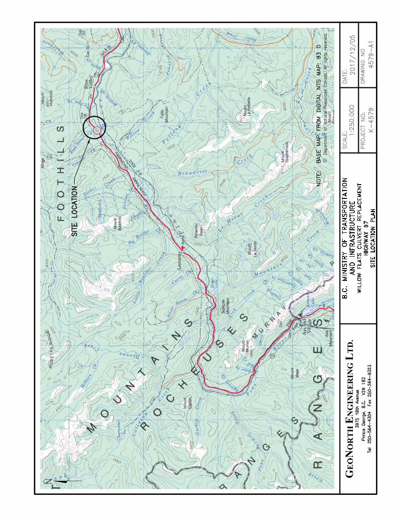
B.C. Ministry of Transportation and Infrastructure (BCMoTI) is investigating the
replacement of a culvert with a new bridge crossing at Willow Flats on Highway 97 about 42 km
west of Chetwynd, B.C. and commissioned GeoNorth Engineering Ltd. (GeoNorth) to carry out
a geotechnical investigation at the crossing. The work was carried out under “As and When”
Contract Number 860C5933, and was coordinated with Stantec Inc., the project managers. The
crossing is at BCMoTI Landmark Kilometre Inventory segment 1161, kilometre 106.09. The
creek at Willow Flats is a tributary of Pine River, with the confluence about 375 m south of the
highway crossing. The site location is shown on Drawing 4579-A1, in Appendix A.
The existing crossing is an approximately 3 m high soil embankment with a 1.2 m
diameter corrugated steel culvert. The new crossing will be a 13.5 m long single-span bridge.
The highway grade at the crossing will be raised by about 1 m at centerline with up to 2 m of
embankment fill to accommodate widening for barrier flares. Project stationing, geometric
details and test hole locations are shown on Drawing 4579-A2, in Appendix A.
This report presents the results of the site investigation, describes existing subsurface
stratigraphy and presents geotechnical recommendations for design and construction of the new
crossing.
2.0 GEOLOGICAL BACKGROUND
The surficial soil deposits at the site are the result of the last glaciation, which ended with
melting of the glacial ice between about 10,000 and 12,000 years before present. Geological
Survey of Canada Bulletin 331 describes the chronology and landforms that were created in 1
Pine Valley during de-glaciation. The Bulletin indicates that early in the de-glaciation process,
Mathews, W. H., 1980. Retreat of the Last Ice Sheets in Northeastern British Columbia and Adjacent1
Alberta, Geological Survey of Canada Bulletin 331.
Page 1 of 14

GEONORTH ENGINEERING LTD.
B.C. Ministry of Transportation and Infrastructure December 5, 2017Geotechnical ReportProposed Culvert Replacement at Willow Flats, about 42 km West of Chetwynd, B.C. File No. K-4579
Pine River Valley, near the site, was inundated by a glacial lake that existed while major stream
channels further east were still covered by glacial ice, preventing drainage of the area. Pine
River Valley had been scoured and deepened by the glacial ice and was subsequently filled with
sediment carried into the glacial lake from the adjacent valley streams. As the ice further east
melted, the lake drained and the resulting stream flow cut into the valley sediments, creating the
present drainage patterns.
Fan deposits from the creek at Willow Flats later deposited over the valley floor. Fan
deposits typically vary horizontally and vertically as a result of the frequent random relocation
of stream flow across the fan. Abandoned channels are sometimes filled with loose soil deposits
and peat. Sand and gravel deposited throughout the active fan areas are subject to high stream
flow and typically has finer grained materials selectively removed.
British Columbia Geological Survey maps maintained by the B.C. Ministry of Energy2
and Mines and Responsible for Core Review show that bedrock in the area is fine grained
sedimentary rocks of the Fort St. John Group, Hulcross Formation.
3.0 SITE INVESTIGATION
Between January 27 and 29, 2017, GeoNorth personnel observed soil and groundwater
conditions in seven drill holes, designated DH17-1, 2, 3, 4, 4B, 5 and 6, located from 200 m
south of the existing culvert to 200 m north. DH17-1, 2, 3, 4B, 5 and 6 were to evaluate the
existing pavement structure and subgrade and DH17-4 was for design of pile foundations for
support of the proposed bridge. Drilling was carried out by Westech Drilling Corp. of Prince
George using cased, air and mud-rotary methods. The drill holes were carried out through the
asphalt surface of the highway to between 2.6 and 3.3 m depth, except for DH17-3 and DH17-4
which were carried out to 7.1 and 31.9 m depth, respectively. DH17-4 was drilled through the
gravel shoulder. The drill hole locations are shown on Drawing 4579-A2. A section along the
http://www.empr.gov.bc.ca/Mining/Geoscience/MapPlace/Pages/default.aspx2
Page 2 of 14
GEONORTH ENGINEERING LTD.
B.C. Ministry of Transportation and Infrastructure December 5, 2017Geotechnical ReportProposed Culvert Replacement at Willow Flats, about 42 km West of Chetwynd, B.C. File No. K-4579
road centreline is shown on Drawing 4579-A3, in Appendix A. After they were completed, drill
holes DH17-1, 2, 4B, 5 and 6 were filled with drill cuttings and bentonite chips and then covered
with an asphalt patch. DH17-3 was filled with sand and covered with an asphalt patch and
DH17-4 was filled with bentonite and cement grout and covered with an asphalt patch.
Standard penetration tests (SPTs) (ASTM D1586) were carried out in all drill holes at
0.75 m intervals to 6 m depth, then at 1.5 m intervals to 15 m depth, and at 3 m intervals. SPT N
values provide an indication of the relative density of a soil deposit, and are used to calculate
foundation bearing capacity and settlement. The SPT also allows a soil sample to be collected.
Our field personnel logged soil conditions based on the samples recovered from the SPT,
supplemented with information provided from the drill cuttings. Thin-walled Shelby tube
(ASTM D1587) samples were obtained in DH17-4 in place of SPTs at selected locations.
Drill hole logs describing subsurface conditions are in Appendix B, and are followed by
an explanation of terms and symbols used on the logs. Laboratory test results are shown on the
logs. A profile showing a summary of conditions encountered in the drill logs is on Drawing
4579-A3.
On February 8, 2017, GeoNorth CPT Investigations Ltd. carried out a cone penetration
test (CPT) (ASTM D5778), designated CPT17-1, using a 5-ton probe equipped to measure tip
stress, shaft friction and soil pore-water pressure. The CPT is carried out using a 45 mm
diameter steel probe with a 60E conical tip and a 200 mm long section of sleeve just above the
tip that are instrumented with load cells to measure soil resistance. It is also equipped with a
pressure transducer that measures the induced soil pore-water pressure that develops at a filter
element between the tip and sleeve as the probe is advanced. All three readings are recorded at
one second intervals in a field computer as the probe is pushed into the ground at a rate of
2 cm/sec using hydraulic rams. CPT17-1 was carried out through DH17-3 to 19.0 m depth. The
CPT location is also shown on Drawing 4579-A2. A CPT log showing tip and sleeve resistance
and the induced pore-water pressures, as well as an interpretation of the test results are in
Appendix B.
Page 3 of 14

GEONORTH ENGINEERING LTD.
B.C. Ministry of Transportation and Infrastructure December 5, 2017Geotechnical ReportProposed Culvert Replacement at Willow Flats, about 42 km West of Chetwynd, B.C. File No. K-4579
We determined the locations of the drill holes by measuring from site landmarks and
using a hand-held GPS device. We estimated the ground surface elevations of the drill holes
from survey information shown on drawings provided by BCMoTI.
4.0 SUBSURFACE CONDITIONS
DH17-1, located 200 m south of the culvert in the centre of the southbound lane,
encountered a 125 mm thick layer of asphalt, over sandy gravel fill to 0.5 m depth, over sandy,
gravelly, silty clay fill to 2.2 m depth, over silty sand fill with some gravel to 2.5 m depth, over
hard, gravelly, sandy, silty clay of intermediate plasticity, likely fill, to the bottom of the hole at
3.3 m depth.
DH17-2, located 110 m south of the culvert in the centre of the northbound lane,
encountered a 125 mm thick layer of asphalt, over sandy gravel fill to 0.5 m depth, over sandy
gravelly silty clay fill to 1.9 m depth, over loose gravelly sand with some fines to the bottom of
the drill hole at 3.3 m depth.
DH17-3, located 10 m south of the culvert in the centre of the southbound lane,
encountered a 125 mm thick layer of asphalt, over sand and gravel fill 2.6 m depth, over layered,
loose sand and silt with a trace amount of gravel to 5.2 m depth, over loose sandy gravel with
a trace to some fines to 6.8 m depth, over soft clayey silt of low plasticity to the bottom of the
drill hole at 7.1 m depth.
DH17-4, located 10 m north of the culvert in the highway shoulder adjacent to the
northbound lane, encountered sandy gravel fill to 1.8 m depth, over compact gravel with some
sand and a trace amount of fines to 2.7 m depth, over very loose sand and silt with a trace amount
of gravel to 4.1 m depth, over compact sandy gravel with a trace amount of fines and occasional
cobbles to 5.8 m depth, over varved, soft silty clay of low to intermediate plasticity to 25.0 m
depth, over stiff to very stiff clayey silt of low plasticity to the bottom of the drill hole at 31.8 m
depth.
Page 4 of 14
GEONORTH ENGINEERING LTD.
B.C. Ministry of Transportation and Infrastructure December 5, 2017Geotechnical ReportProposed Culvert Replacement at Willow Flats, about 42 km West of Chetwynd, B.C. File No. K-4579
DH17-4B, located 10 m north of the culvert in the centre of the northbound lane,
encountered a layer of asphalt 200 mm thick, over sand and gravel fill to 1.2 m depth, over
layered silty sand to 1.5 m depth, over compact sandy gravel with some fines to the bottom of
the drill hole at 2.6 m depth.
DH17-5, located 100 m north of the culvert in the centre of the southbound lane
encountered a layer of asphalt 100 mm thick, over sandy gravel fill to 0.6 m depth, over silty,
sandy, gravelly clay fill to the bottom of the drill hole at 3.4 m depth.
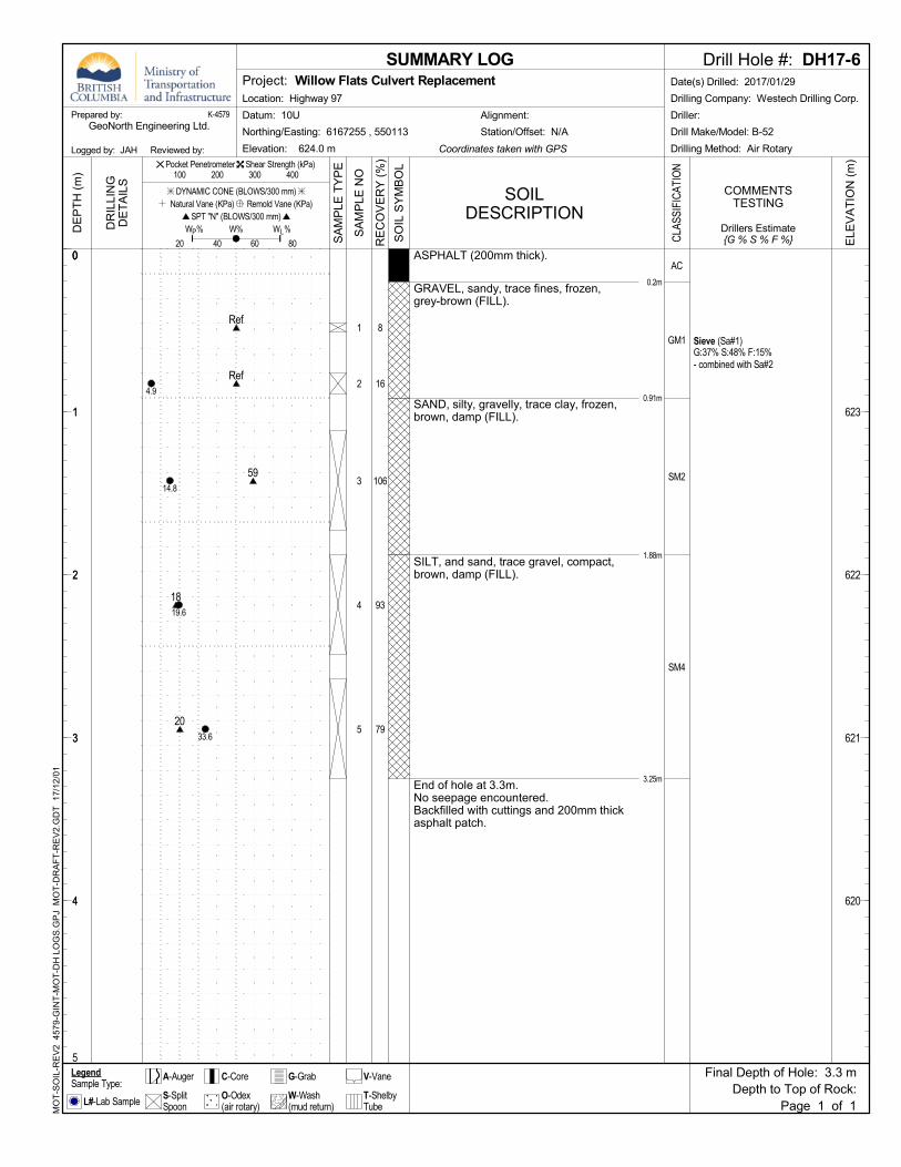
DH17-6, located 200 m north of the culvert in the centre of the northbound lane
encountered a layer of asphalt 200 mm thick, over sandy gravel fill to 1.9 m depth, over silt and
sand fill with a trace amount of gravel to the bottom of the drill hole at 3.3 m depth.
Seepage was observed in DH17-3 below 4.6 m depth and 4.3 m in DH17-4.
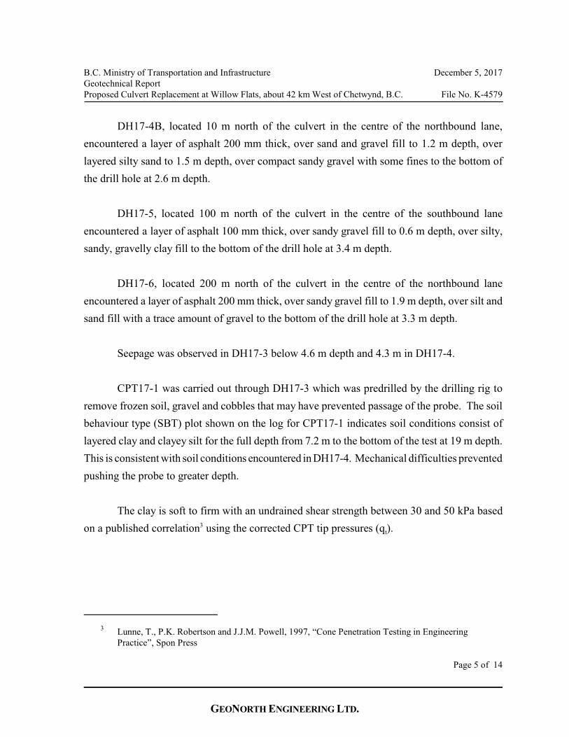
CPT17-1 was carried out through DH17-3 which was predrilled by the drilling rig to
remove frozen soil, gravel and cobbles that may have prevented passage of the probe. The soil
behaviour type (SBT) plot shown on the log for CPT17-1 indicates soil conditions consist of
layered clay and clayey silt for the full depth from 7.2 m to the bottom of the test at 19 m depth.
This is consistent with soil conditions encountered in DH17-4. Mechanical difficulties prevented
pushing the probe to greater depth.
The clay is soft to firm with an undrained shear strength between 30 and 50 kPa based
ton a published correlation using the corrected CPT tip pressures (q ).3
Lunne, T., P.K. Robertson and J.J.M. Powell, 1997, “Cone Penetration Testing in Engineering3
Practice”, Spon Press
Page 5 of 14

GEONORTH ENGINEERING LTD.
B.C. Ministry of Transportation and Infrastructure December 5, 2017Geotechnical ReportProposed Culvert Replacement at Willow Flats, about 42 km West of Chetwynd, B.C. File No. K-4579
tCorrelations between CPT tip pressure (q ) and over-consolidation ratio (OCR) show the
clay encountered in the test is normally or slightly over-consolidated with an OCR ranging
between 1 and 2. OCR is defined as the highest stress experienced by the deposit divided by the
current stress. Normally or slightly over-consolidated deposits are more susceptible to settlement
than heavily over-consolidated deposits.
5.0 DISCUSSION AND RECOMMENDATIONS
The results of the two deeper drill holes from the site investigation show that granular
alluvial fan deposits at this site extend to 5.8 and 6.8 m depth, and cover weak compressible silty
clay, the glaciolacustrine sediments. The relatively more competent fan deposits are too thin to
provide adequate support for proposed bridge foundations therefore, we recommend the bridge
be supported on driven pipe pile foundations that penetrate the weak, compressible sediments
to bear in the stiff silt below 25 m depth. H-piles were considered as a foundation option but in
this case are less efficient than driven pipe piles.
The following sections address estimated embankment settlement, pile design and
installation, embankment construction, and pavement structure design, including transitions
The recommendations in this report are based on the necessary assumption that
conditions encountered in the drill holes and cone penetration test are representative of
conditions elsewhere. Please contact our office for additional recommendations if conditions
encountered during construction differ in any way from those described in this report.
5.1 Embankment Settlement Analysis
The clay encountered in the investigation has properties of low shear strength and high
potential for consolidation under the weight of embankment fill. Consolidation occurs when an
applied load causes an increase in stress that exceeds the preconsolidation pressure of a soil.
The stress caused by embankment fill extends to a depth equal to roughly three times its width,
Page 6 of 14
GEONORTH ENGINEERING LTD.
B.C. Ministry of Transportation and Infrastructure December 5, 2017Geotechnical ReportProposed Culvert Replacement at Willow Flats, about 42 km West of Chetwynd, B.C. File No. K-4579
but the increase in stress drops to about 10% of the imposed load at a depth equal to twice its
width. The soft clay is within the zone of stress increase and is close to being normally
consolidated, and is therefore subject to consolidation settlement caused by the weight of
embankment fill.
Consolidation occurs over a period of time as excess pore-water pressure, induced by the
applied load, is allowed to dissipate. The length of time for this process to occur depends on the
hydraulic conductivity of the soil, on soil stratigraphy and the distance between permeable layers
that allow drainage.
The highway grade at the crossing will be raised by about 1 m at centerline with up to
2 m of embankment fill to accommodate widening for barrier flares. To determine the amount
of settlement below the proposed 2 m of embankment fill, we developed a geological model
based on the drilling and CPT results, and used the program Sigma/W version 2016, by
Geo-Slope International, Inc. to estimate consolidation settlements and checked the results with
hand-calculation methods. Our analysis indicates less than 3 cm of settlement will occur below
the proposed 2 m high embankment fill, with about 1 cm of differential settlement between the
embankment shoulder and centre line. We estimate the accuracy of the settlement calculation
is about +/- 50% of the calculated values. Approximately 50% of the total settlement will occur
within six months of the embankment fill being placed and the remaining amount over a period
of about 12 months.
5.2 Pile Foundations
Pile capacity will depend on both shaft friction and end bearing resistance, as well as the
pile stiffness (wall thickness and length), the energy of the pile driving equipment, and the
penetration resistance at end-of-driving.
Based on the preferred bridge configuration, the abutments will be supported on five
piles. Klohn Crippen Berger Ltd. (KCB), the structural engineers for the project, indicate that
Page 7 of 14

GEONORTH ENGINEERING LTD.
B.C. Ministry of Transportation and Infrastructure December 5, 2017Geotechnical ReportProposed Culvert Replacement at Willow Flats, about 42 km West of Chetwynd, B.C. File No. K-4579
each pile will require a factored geotechnical resistance of 670 kN (Ultimate Limit States (ULS))
and 500 kN (Service Limit States (SLS)). We carried out pile capacity analyses using several
procedures as described in the Canadian Foundation Engineering Manual, Fourth Edition (2006)
to determine the pile diameter and length required to support the design loads. The results are
summarized in Table 1, below.
Table 1 - Axial Capacity and Minimum Pile Tip Elevation
Pile
Diameter
Wall
Thickness
Ultimate
Axial Pile
Capacity
Factored
Geotechnical
Resistance
(ULS)
Allowable
Pile Capacity
(SLS)
Minimum
Pile Tip
Elevation
610 mm 9.5 mm 1680 kN 670 kN 500 kN 595 m*
* Minimum pile tip elevation assumes the maximum scour depth is elevation 620 m.
The ultimate axial pile capacity was calculated using a geotechnical resistance factor
(GRF) of 0.40 applied to the factored geotechnical resistance. The GRF is based on the average
between 0.45 and 0.35 recommended in the Canadian Highway Bridge Design Code, 2014 to
reflect the use of CPT data to elevation 605 m and SPT data below this elevation. We can
provide recommendations for other pile sizes and lengths at your request.
We analysed the driveability of a 610 mm diameter open-ended steel pipe pile with a 9.5
mm wall thickness using the computer program GRL WEAP by GRL Engineers Inc. (2005).
Our analysis indicates the shaft would contribute about 90% of the total pile resistance. A
summary of the analysis is shown in Table 2, below.
Page 8 of 14

GEONORTH ENGINEERING LTD.
B.C. Ministry of Transportation and Infrastructure December 5, 2017Geotechnical ReportProposed Culvert Replacement at Willow Flats, about 42 km West of Chetwynd, B.C. File No. K-4579
Table 2 - Preliminary Pile Driving Analysis
Pile
Diameter
Wall
Thickness
Ultimate
Capacity
Driving
Energy
End-of-Driving
Penetration Resistance
Maximum Pile
Stress
610 mm 9.5 mm 1680 kN 80 kJ 35 blows per 300 mm 165 MPa
Based on the estimated maximum pile stress we recommend using piles manufactured
with Grade 2 or 3 steel (ASTM A252).
Piles installed before consolidation from the weight of embankment fill is complete will
be subjected to negative shaft friction and downdrag. As noted above, we estimate the
embankment could settle by 3 cm based on a 2 m increase in the height of the embankment. The
amount of pile foundation settlement will be less, and will depend on how soon after the
embankment is constructed the piles are installed. Differential settlement between abutments
could be as high as about one-half the total settlement. Most of the anticipated settlement is
likely to occur within one year of construction.
We used the program LPile by Ensoft Inc. (2016) to estimate lateral deflection under a
44 kN lateral load provided by KCB. Inputs to the program included the soil conditions
encountered during the investigation, a 44 kN horizontal load applied to the top of a 610 mm
diameter by 9.5 mm wall thickness pipe pile, and a scour depth at elevation 620 m, about 1 m
below the bottom of the existing culvert. The results of the analysis indicate about 2 cm of
deflection, assuming the pile head is not free to rotate. We can carry out additional analysis at
your request.
Page 9 of 14

GEONORTH ENGINEERING LTD.
B.C. Ministry of Transportation and Infrastructure December 5, 2017Geotechnical ReportProposed Culvert Replacement at Willow Flats, about 42 km West of Chetwynd, B.C. File No. K-4579
5.3 Bridge End Fill
Construct bridge end fill following the BCMoTI Standard Specifications, Section 202.
Use clean granular soil that meets the gradation specifications for Bridge End Fill. Place the fill
in thin uniform layers and compact each layer to at least 100% SPD. Add water or dry the fill
as required to achieve the specified density. The layer thickness will depend on the size of
compaction equipment, moisture conditions and other variables, but do not exceed 150 mm.
Design the abutments to withstand lateral pressures caused by soil, compaction, seismic
loads, and any surcharges. Drawing 4579-C1, in Appendix C, shows typical lateral earth
pressures that can develop against a restrained wall. It assumes that the wall is unyielding and
othat the fill is free-draining. The at-rest (K ) and seismic loads will apply for all restrained walls.
oUse an at-rest coefficient of lateral earth pressure, K , of 0.38 and a soil density of 22 kN/m . 3
Add the pressures from compaction and vehicle loading where they are appropriate.
5.4 Seismic Site Class
The 2014 Canadian Highway Bridge Design Code defines the "Site Classification for
Seismic Site Response" in Table 4.1, based on properties of the soil to 30 m depth at the site.
Based on the results of the CPT we calculate the Site Classification for Seismic Site
Response to be Site Class “E”, as defined in Table 4.1.
Liquefaction is not anticipated at this site due to the high fines content in the soil.
5.5 Earth Embankment Fills and Barrier Flare Embankment Widening
Construct earth embankment fills and barrier flare embankment widening following the
BCMoTI Standard Specifications, Section 201. Use temporary excavation slopes no steeper than
1H:1V.
Page 10 of 14

GEONORTH ENGINEERING LTD.
B.C. Ministry of Transportation and Infrastructure December 5, 2017Geotechnical ReportProposed Culvert Replacement at Willow Flats, about 42 km West of Chetwynd, B.C. File No. K-4579
We recommend constructing embankments using mineral soil free of organic and
deleterious material and containing less than 15% by volume of rock larger than 150 mm.
Granular material excavated from the existing embankment may be reused as embankment fill
provided it can be compacted to the specified density. Based on the moderate susceptibility to
frost heave of the sandy gravel, we recommend constructing embankment end-fill slopes no
steeper than 2.5H:1V to achieve a factor of safety of 1.5. We recommend using finished
embankment fill slopes no steeper than 2H:1V for granular fill, with a fines content less than
10%.
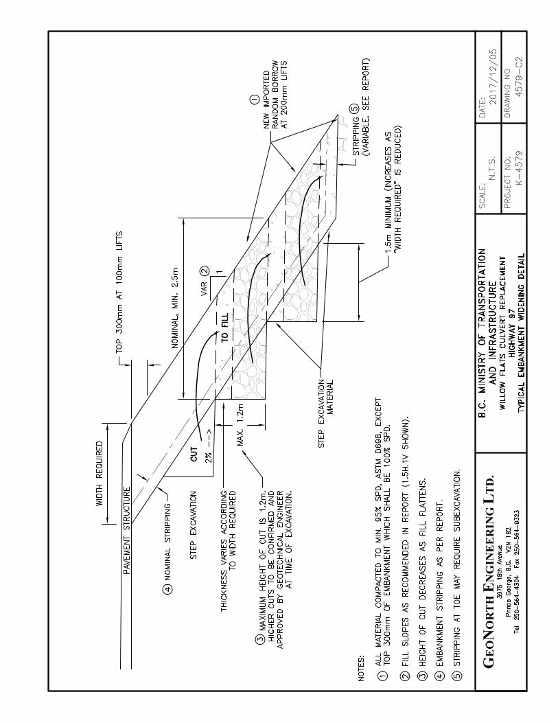
In some areas the surface of the existing embankment will be covered with winter road
sand, grass, and brush. We recommend stripping the surface of the embankment to expose
compact mineral soil. Key new fill into the existing embankment using benches. Cut the
benches into the existing embankment using a minimum bench width of 1.5 m and a maximum
height of 1.2 m. If suitable, the material from the bench can be incorporated into the new
embankment. Slope the bench surfaces at a gradient of 2% towards the outside slope face. A
conceptual cross section showing this detail is on Drawing 4579-C2, in Appendix C.
Place the embankment fill in thin, uniform layers and compact each layer to at least 95%
SPD, and to at least 100% SPD within 300 mm of the top of subgrade, at a moisture content
within 2% of optimum. The maximum layer thickness will depend on several factors, including
compactor type, size and energy, and the soil type and moisture content, but do not use a layer
thickness more than 200 mm. Add water and dry the fill as necessary to attain the specified
density and moisture content.
Protect the embankment end-fill from erosion up to the 200 year design flood elevation.
Place a geotextile separator between the embankment fill and rip rap to prevent sand and silt in
the embankment from migrating into the rip rap. Use a nonwoven geotextile that has a puncture
strength (ASTM D6241) of at least 1.9 kN at 50% elongation, and an apparent opening size
(ASTM D4751) no larger than 0.25 mm (average maximum roll value). Place suitably sized rip
rap over the geotextile in uniform layers no more than 1 m thick and work the rock into place
using an excavator bucket.
Page 11 of 14

GEONORTH ENGINEERING LTD.
B.C. Ministry of Transportation and Infrastructure December 5, 2017Geotechnical ReportProposed Culvert Replacement at Willow Flats, about 42 km West of Chetwynd, B.C. File No. K-4579
5.6 Pavement Structure
We recommend the following pavement structure:
• 125 mm of Asphalt Pavement (Class 1), over
• 300 mm of 25 mm Well Graded Base (WGB) or 25 mm Intermediate Graded
Base (IGB), over
• 600 mm of Select Granular Subbase (SGSB), over
• A prepared subgrade.
Construct all components of the new pavement structure with at least a 2% crossfall to
the outside. Use a medium weight, non-woven geotextile as a separator between the pavement
structure and subgrade, if more than 50% of the subgrade soil passes the 0.075 mm sieve. Use
a geotextile that meets the following Minimum Average Roll Values (MARV).
• Grab Tensile Strength (ASTM D4632) greater than 700 N,
• Grab Tensile Elongation (ASTM D4632) greater than 50%,
• Static Puncture (D6241) greater than 1375 N,
• Trapezoid Tear (ASTM D4533) greater than 250 N,
• Apparent Opening Size (ASTM D4751) 0.22 mm + 0.02 mm.
Where the new structure ties into the existing structure we recommend using a saw cut
between 20E and 30E from perpendicular to the road centreline. At the face of the saw cut, leave
an undisturbed width of existing crushed base 500 mm wide, then begin excavation of a
transition slope of 8H:1V to accommodate the new pavement structure thickness. A conceptual
transition detail is shown on Drawing 4579-C3, in Appendix C.
Page 12 of 14

GEONORTH ENGINEERING LTD.
B.C. Ministry of Transportation and Infrastructure December 5, 2017Geotechnical ReportProposed Culvert Replacement at Willow Flats, about 42 km West of Chetwynd, B.C. File No. K-4579
5.7 Aggregates and Fill
Four material types are specified for construction of the pavement structure and bridge
embankment noted above:
• 25 mm Well Graded Base (WGB),
• 25 mm Intermediate Graded Base (IGB),
• Select Granular Subbase (SGSB),
• Bridge End Fill (BEF).
Use material that meets BCMoTI’s specifications noted in Section 202 of the 2012
Standard Specifications for Highway Construction.
6.0 CONSTRUCTION REVIEW
We recommend that we review final design drawings to confirm that the intent of our
recommendations have been applied, that the recommendations in this report are appropriate and
that sufficient geotechnical investigation has been carried out.
We recommend that an experienced geotechnical engineer, or their designate, review
critical aspects of the project to confirm that soil conditions are as expected and that construction
materials, their placement and their level of compaction are as specified. If soil conditions or
construction materials are different than expected, we can provide additional recommendations
to address the actual conditions. We consider the following geotechnical aspects of the work as
being critical to the project:
• Removal of soft or deleterious soil below areas of fill,
• Gradation, durability, placement and compaction of fill, and
• Pile installation, and whether a PDA with a CAPWAP are required.
Page 13 of 14


GEONORTH ENGINEERING LTD.
B.C. Ministry of Transportation and Infrastructure December 5, 2017Geotechnical ReportProposed Culvert Replacement at Willow Flats, about 42 km West of Chetwynd, B.C. File No. K-4579
A P P E N D I X A

GEONORTHENGINEERING LTD.


GEONORTH ENGINEERING LTD.
B.C. Ministry of Transportation and Infrastructure December 5, 2017Geotechnical ReportProposed Culvert Replacement at Willow Flats, about 42 km West of Chetwynd, B.C. File No. K-4579
A P P E N D I X B

0.13m
0.51m
2.18m
2.49m
3.3m
AC
GP-GM
CL
SM3
CL
1
2
3
4
268
103
84
44
ASPHALT (125mm thick).
GRAVEL, sandy, trace to some fines,frozen, brown (FILL).
CLAY, gravelly, sandy, silty, subangulargravel, hard, low plasticity, brown, Wn<Wp(likely FILL).
SAND, silty, some gravel, trace clay,compact, brown, damp (likely FILL).
CLAY, gravelly, sandy, silty, subangulargravel, hard, low plasticity, brown,Wn<Wp.
End of hole at 3.3m.No seepage encountered.Backfilled with bentonite 2.1 to 3.3m,cuttings to surface with 130mm thickasphalt patch.
Atterberg (Sa#2):PL:18% LL:22%
L#-Lab SampleW-Wash(mud return)
Elevation: 624.0 m
623
622
621
620
GeoNorth Engineering Ltd.Prepared by:
ELE
VA
TIO
N (
m)
1
2
3
4
LegendSample Type:
S-SplitSpoon
O-Odex(air rotary)
T-ShelbyTube
C-CoreA-Auger G-Grab V-Vane
1
2
3
4
Driller:
Drill Make/Model: B-52
CLA
SSIF
ICAT
ION
Location: Highway 97
Date(s) Drilled: 2017/01/27
Drilling Method: Air RotaryCoordinates taken with GPS
Project: Willow Flats Culvert Replacement
Logged by: JAH Reviewed by:
SO
IL S
YM
BO
L
Drill Hole #: DH17-1
RE
CO
VE
RY
(%
)
SA
MP
LE N
O
SA
MP
LE T
YP
E
SOILDESCRIPTION
00
Page 1 of 1
DE
PT
H (
m)
DR
ILLI
NG
DE
TA
ILS
Alignment:
5
0
Northing/Easting: 6167016 , 549780
Final Depth of Hole: 3.3 mDepth to Top of Rock:
Station/Offset: N/A
COMMENTSTESTING
Drillers Estimate{G % S % F %}
Drilling Company: Westech Drilling Corp.
K-4579
SUMMARY LOG
Datum: 10U
MO
T-S
OIL
-RE
V2
457
9-G
INT
-MO
T-D
H L
OG
S.G
PJ
MO
T-D
RA
FT
-RE
V2.
GD
T
17/1
2/0
1
DYNAMIC CONE (BLOWS/300 mm)
W % LW %
20 40 60 80P W%
SPT "N" (BLOWS/300 mm) Natural Vane (KPa) Remold Vane (KPa)
100 200 300 400 Pocket Penetrometer Shear Strength (kPa)
Ref
97
32
18
16.3
12.9
18.8
7.8

0.13m
0.46m
1.88m
3.25m
AC
GP
CL
SM2
1
2
3
4
171
133
33
51
ASPHALT (125mm thick).
GRAVEL, sandy, trace fines, frozen,brown (FILL).
CLAY, gravelly, sandy, silty, frozen, lowplasticity, Wn<Wp (likely FILL).
SAND, gravelly, some fines, loose, brown,damp.
- below 2.6m, trace gravel, layeringapparent, very loose.
End of hole at 3.3m.No seepage encountered.Backfilled with bentonite 2.1 to 3.3m,cuttings to surface with 130mm thickasphalt patch.
Atterberg (Sa#2):PL:16% LL:21%
L#-Lab SampleW-Wash(mud return)
Elevation: 624.0 m
623
622
621
620
GeoNorth Engineering Ltd.Prepared by:
ELE
VA
TIO
N (
m)
1
2
3
4
LegendSample Type:
S-SplitSpoon
O-Odex(air rotary)
T-ShelbyTube
C-CoreA-Auger G-Grab V-Vane
1
2
3
4
Driller:
Drill Make/Model: B-52
CLA
SSIF
ICAT
ION
Location: Highway 97
Date(s) Drilled: 2017/01/27
Drilling Method: Air RotaryCoordinates taken with GPS
Project: Willow Flats Culvert Replacement
Logged by: JAH Reviewed by:
SO
IL S
YM
BO
L
Drill Hole #: DH17-2
RE
CO
VE
RY
(%
)
SA
MP
LE N
O
SA
MP
LE T
YP
E
SOILDESCRIPTION
00
Page 1 of 1
DE
PT
H (
m)
DR
ILLI
NG
DE
TA
ILS
Alignment:
5
0
Northing/Easting: 6167069 , 549859
Final Depth of Hole: 3.3 mDepth to Top of Rock:
Station/Offset: 100+91, 0.9m Rt
COMMENTSTESTING
Drillers Estimate{G % S % F %}
Drilling Company: Westech Drilling Corp.
K-4579
SUMMARY LOG
Datum: 10U
MO
T-S
OIL
-RE
V2
457
9-G
INT
-MO
T-D
H L
OG
S.G
PJ
MO
T-D
RA
FT
-RE
V2.
GD
T
17/1
2/0
1
DYNAMIC CONE (BLOWS/300 mm)
W % LW %
20 40 60 80P W%
SPT "N" (BLOWS/300 mm) Natural Vane (KPa) Remold Vane (KPa)
100 200 300 400 Pocket Penetrometer Shear Strength (kPa)
Ref
Ref
9
4
6.2
6.2
6.5
13.7

0.13m
0.3m
0.91m
2.64m
5.23m
6.76m
7.06m
AC
GM
GP
SM3
SM4
GP
ML
1
2
3
4
5
6
7
8
9
10
223
149
100
87
16
106
8
57
49
62
ASPHALT (125mm thick).SAND, gravelly, some fines, frozen, brown(25mm crush).GRAVEL, sandy, trace fines, frozen,brown, damp (FILL).
SAND, gravelly, silty, trace to some clay,frozen, damp (likely FILL).
SAND, and silt, trace gravel, layered, veryloose to loose, wet to saturated, slowdilatancy, occasional silt lenses.
- below 4.2m, trace to some fines, loose,saturated, layered with gravel, rapiddilatancy.
GRAVEL, sandy, trace to some fines,layered, compact, brown, damp.
- below 5.7m, saturated, loose.
SILT, clayey, some sand, layered, soft, lowplasticity, grey-blue, Wn>Wp.
End of hole at 7.1m.Groundwater measured at 4.58m depth(2017/01/29).Backfilled with sand for CPT.
L#-Lab SampleW-Wash(mud return)
Elevation: 624.0 m
623
622
621
620
619
618
617
GeoNorth Engineering Ltd.Prepared by:
ELE
VA
TIO
N (
m)
1
2
3
4
5
6
7
LegendSample Type:
S-SplitSpoon
O-Odex(air rotary)
T-ShelbyTube
C-CoreA-Auger G-Grab V-Vane
1
2
3
4
5
6
7
Driller:
Drill Make/Model: B-52
CLA
SSIF
ICAT
ION
Location: Highway 97
Date(s) Drilled: 2017/01/29
Drilling Method: Air RotaryCoordinates taken with GPS
Project: Willow Flats Culvert Replacement
Logged by: JAH Reviewed by:
SO
IL S
YM
BO
L
Drill Hole #: DH17-3
RE
CO
VE
RY
(%
)
SA
MP
LE N
O
SA
MP
LE T
YP
E
SOILDESCRIPTION
00
Page 1 of 1
DE
PT
H (
m)
DR
ILLI
NG
DE
TA
ILS
Alignment:
8
0
Northing/Easting: 6167136 , 549935
Final Depth of Hole: 7.1 mDepth to Top of Rock:
Station/Offset: 101+92, 4.8m Lt
COMMENTSTESTING
Drillers Estimate{G % S % F %}
Drilling Company: Westech Drilling Corp.
K-4579
SUMMARY LOG
Datum: 10U
MO
T-S
OIL
-RE
V2
457
9-G
INT
-MO
T-D
H L
OG
S.G
PJ
MO
T-D
RA
FT
-RE
V2.
GD
T
17/1
2/0
1
DYNAMIC CONE (BLOWS/300 mm)
W % LW %
20 40 60 80P W%
SPT "N" (BLOWS/300 mm) Natural Vane (KPa) Remold Vane (KPa)
100 200 300 400 Pocket Penetrometer Shear Strength (kPa)
Ref
>>127
89
60
5
1
7
23
9
5
4.4
8.1
9.9
9.6
13.7
31.7
16.2
16.1
38.5

1.83m
2.74m
4.11m
5.79m
GM2
GP
SM4
GP
1
2
3
4
5
6
7
8
9
10
- combined with Sa#2
88
79
30
106
88
80
70
57
111
95
GRAVEL, sandy, some fines, frozen,brown (likely FILL).
GRAVEL, some sand, trace fines, layered,compact, brown, damp.
SAND, and silt, trace gravel, layered, veryloose, brown, slow dilatancy, wet.
GRAVEL, sandy, trace fines, layered,compact, brown, isolated cobbles, dampto moist.
- below 5.0m, some fines, wet.
CLAY, silty, trace sand, varved, soft, low tointermediate plasticity, grey-blue,occasional sand lenses, Wn>Wp.
Sieve (Sa#1)G:38% S:39% F:23%
Atterberg (Sa#10):PL:24% LL:44%
L#-Lab SampleW-Wash(mud return)
Elevation: 623.5 m
623
622
621
620
619
618
617
616
615
614
GeoNorth Engineering Ltd.Prepared by:
ELE
VA
TIO
N (
m)
1
2
3
4
5
6
7
8
9
LegendSample Type:
S-SplitSpoon
O-Odex(air rotary)
T-ShelbyTube
C-CoreA-Auger G-Grab V-Vane
1
2
3
4
5
6
7
8
9
Driller:
Drill Make/Model: B-52
CLA
SSIF
ICAT
ION
Location: Highway 97
Date(s) Drilled: 2017/01/28&29
Drilling Method: Air/Mud RotaryCoordinates taken with GPS
Project: Willow Flats Culvert Replacement
Logged by: JAH Reviewed by:
SO
IL S
YM
BO
L
Drill Hole #: DH17-4
RE
CO
VE
RY
(%
)
SA
MP
LE N
O
SA
MP
LE T
YP
E
SOILDESCRIPTION
00
Page 1 of 4
DE
PT
H (
m)
DR
ILLI
NG
DE
TA
ILS
Alignment:
10
0
Northing/Easting: 6167137 , 549959
Final Depth of Hole: 31.9 mDepth to Top of Rock:
Station/Offset: 102+13, 9.2m Rt
COMMENTSTESTING
Drillers Estimate{G % S % F %}
Drilling Company: Westech Drilling Corp.
K-4579
SUMMARY LOG
Datum: 10U
MO
T-S
OIL
-RE
V2
457
9-G
INT
-MO
T-D
H L
OG
S.G
PJ
MO
T-D
RA
FT
-RE
V2.
GD
T
17/1
2/0
1
DYNAMIC CONE (BLOWS/300 mm)
W % LW %
20 40 60 80P W%
SPT "N" (BLOWS/300 mm) Natural Vane (KPa) Remold Vane (KPa)
100 200 300 400 Pocket Penetrometer Shear Strength (kPa)
69
27
15
2
2
15
24
5
4
6.2
4.3
5.1
29.3
28.7
10.2
14.2
23.3
40.8
39.7

CL
11
12
13
14
15
16
120
115
115
92
115
102
CLAY, silty, trace sand, varved, soft, low tointermediate plasticity, grey-blue,occasional sand lenses, Wn>Wp.(continued)- below 10.2m, very soft, Wn near WL.
- at 12.95 m, colour changes to dark grey.
Atterberg (Sa#14):PL:23% LL:41%
L#-Lab SampleW-Wash(mud return)
Elevation: 623.5 m
613
612
611
610
609
608
607
606
605
604
GeoNorth Engineering Ltd.Prepared by:
ELE
VA
TIO
N (
m)
11
12
13
14
15
16
17
18
19
LegendSample Type:
S-SplitSpoon
O-Odex(air rotary)
T-ShelbyTube
C-CoreA-Auger G-Grab V-Vane
11
12
13
14
15
16
17
18
19
Driller:
Drill Make/Model: B-52
CLA
SSIF
ICAT
ION
Location: Highway 97
Date(s) Drilled: 2017/01/28&29
Drilling Method: Air/Mud RotaryCoordinates taken with GPS
Project: Willow Flats Culvert Replacement
Logged by: JAH Reviewed by:
SO
IL S
YM
BO
L
Drill Hole #: DH17-4
RE
CO
VE
RY
(%
)
SA
MP
LE N
O
SA
MP
LE T
YP
E
SOILDESCRIPTION
1010
Page 2 of 4
DE
PT
H (
m)
DR
ILLI
NG
DE
TA
ILS
Alignment:
20
10
Northing/Easting: 6167137 , 549959
Final Depth of Hole: 31.9 mDepth to Top of Rock:
Station/Offset: 102+13, 9.2m Rt
COMMENTSTESTING
Drillers Estimate{G % S % F %}
Drilling Company: Westech Drilling Corp.
K-4579
SUMMARY LOG
Datum: 10U
MO
T-S
OIL
-RE
V2
457
9-G
INT
-MO
T-D
H L
OG
S.G
PJ
MO
T-D
RA
FT
-RE
V2.
GD
T
17/1
2/0
1
DYNAMIC CONE (BLOWS/300 mm)
W % LW %
20 40 60 80P W%
SPT "N" (BLOWS/300 mm) Natural Vane (KPa) Remold Vane (KPa)
100 200 300 400 Pocket Penetrometer Shear Strength (kPa)
0
5
3
39.4
37.5
37.8
37.2
42

25.15m
ML
17
18
19
102
98
74
CLAY, silty, trace sand, varved, soft, low tointermediate plasticity, grey-blue,occasional sand lenses, Wn>Wp.(continued)
SILT, clayey, trace sand, layered, stiff tovery stiff, low plasticity, grey, slowdilatancy, Wn>Wp.
Atterberg (Sa#18):PL:23% LL:27%
L#-Lab SampleW-Wash(mud return)
Elevation: 623.5 m
603
602
601
600
599
598
597
596
595
594
GeoNorth Engineering Ltd.Prepared by:
ELE
VA
TIO
N (
m)
21
22
23
24
25
26
27
28
29
LegendSample Type:
S-SplitSpoon
O-Odex(air rotary)
T-ShelbyTube
C-CoreA-Auger G-Grab V-Vane
21
22
23
24
25
26
27
28
29
Driller:
Drill Make/Model: B-52
CLA
SSIF
ICAT
ION
Location: Highway 97
Date(s) Drilled: 2017/01/28&29
Drilling Method: Air/Mud RotaryCoordinates taken with GPS
Project: Willow Flats Culvert Replacement
Logged by: JAH Reviewed by:
SO
IL S
YM
BO
L
Drill Hole #: DH17-4
RE
CO
VE
RY
(%
)
SA
MP
LE N
O
SA
MP
LE T
YP
E
SOILDESCRIPTION
2020
Page 3 of 4
DE
PT
H (
m)
DR
ILLI
NG
DE
TA
ILS
Alignment:
30
20
Northing/Easting: 6167137 , 549959
Final Depth of Hole: 31.9 mDepth to Top of Rock:
Station/Offset: 102+13, 9.2m Rt
COMMENTSTESTING
Drillers Estimate{G % S % F %}
Drilling Company: Westech Drilling Corp.
K-4579
SUMMARY LOG
Datum: 10U
MO
T-S
OIL
-RE
V2
457
9-G
INT
-MO
T-D
H L
OG
S.G
PJ
MO
T-D
RA
FT
-RE
V2.
GD
T
17/1
2/0
1
DYNAMIC CONE (BLOWS/300 mm)
W % LW %
20 40 60 80P W%
SPT "N" (BLOWS/300 mm) Natural Vane (KPa) Remold Vane (KPa)
100 200 300 400 Pocket Penetrometer Shear Strength (kPa)
6
15
32.8
26.4
25.5

31.85m
20 82
SILT, clayey, trace sand, layered, stiff tovery stiff, low plasticity, grey, slowdilatancy, Wn>Wp. (continued)
End of hole at 31.9m.Groundwater measured at 4.3m depth(2017/01/28).Backfilled with grout, then bentonite in top1.5m.
L#-Lab SampleW-Wash(mud return)
Elevation: 623.5 m
593
592
591
590
589
588
587
586
585
584
GeoNorth Engineering Ltd.Prepared by:
ELE
VA
TIO
N (
m)
31
32
33
34
35
36
37
38
39
LegendSample Type:
S-SplitSpoon
O-Odex(air rotary)
T-ShelbyTube
C-CoreA-Auger G-Grab V-Vane
31
32
33
34
35
36
37
38
39
Driller:
Drill Make/Model: B-52
CLA
SSIF
ICAT
ION
Location: Highway 97
Date(s) Drilled: 2017/01/28&29
Drilling Method: Air/Mud RotaryCoordinates taken with GPS
Project: Willow Flats Culvert Replacement
Logged by: JAH Reviewed by:
SO
IL S
YM
BO
L
Drill Hole #: DH17-4
RE
CO
VE
RY
(%
)
SA
MP
LE N
O
SA
MP
LE T
YP
E
SOILDESCRIPTION
3030
Page 4 of 4
DE
PT
H (
m)
DR
ILLI
NG
DE
TA
ILS
Alignment:
40
30
Northing/Easting: 6167137 , 549959
Final Depth of Hole: 31.9 mDepth to Top of Rock:
Station/Offset: 102+13, 9.2m Rt
COMMENTSTESTING
Drillers Estimate{G % S % F %}
Drilling Company: Westech Drilling Corp.
K-4579
SUMMARY LOG
Datum: 10U
MO
T-S
OIL
-RE
V2
457
9-G
INT
-MO
T-D
H L
OG
S.G
PJ
MO
T-D
RA
FT
-RE
V2.
GD
T
17/1
2/0
1
DYNAMIC CONE (BLOWS/300 mm)
W % LW %
20 40 60 80P W%
SPT "N" (BLOWS/300 mm) Natural Vane (KPa) Remold Vane (KPa)
100 200 300 400 Pocket Penetrometer Shear Strength (kPa)
31.6

0.2m
0.3m
0.76m
1.22m
1.52m
2.59m
AC
GM2
GM1
GM2
SM2
GM2
1
2
3
4
105
123
110
49
ASPHALT (200mm thick).
SAND, gravelly, some fines, frozen,brown, damp (25mm crush).GRAVEL, sandy, some fines, frozen,brown, damp (FILL).
GRAVEL, sandy, silty, some clay, frozen,brown, damp (FILL).
SAND, silty, trace gravel, layered, frozen,brown-black, trace organic soil.
GRAVEL, sandy, some silt, layered,compact, brown, rust staining, damp.
End of hole at 2.6m.No seepage encountered.Backfilled with cuttings, 200mm thickasphalt patch.
L#-Lab SampleW-Wash(mud return)
Elevation: 624.0 m
623
622
621
620
GeoNorth Engineering Ltd.Prepared by:
ELE
VA
TIO
N (
m)
1
2
3
4
LegendSample Type:
S-SplitSpoon
O-Odex(air rotary)
T-ShelbyTube
C-CoreA-Auger G-Grab V-Vane
1
2
3
4
Driller:
Drill Make/Model: B-52
CLA
SSIF
ICAT
ION
Location: Highway 97
Date(s) Drilled: 2017/01/29
Drilling Method: Air RotaryCoordinates taken with GPS
Project: Willow Flats Culvert Replacement
Logged by: JAH Reviewed by:
SO
IL S
YM
BO
L
Drill Hole #: DH17-4B
RE
CO
VE
RY
(%
)
SA
MP
LE N
O
SA
MP
LE T
YP
E
SOILDESCRIPTION
00
Page 1 of 1
DE
PT
H (
m)
DR
ILLI
NG
DE
TA
ILS
Alignment:
5
0
Northing/Easting: 6167138 , 549948
Final Depth of Hole: 2.6 mDepth to Top of Rock:
Station/Offset: 102+05, 1.6m Rt
COMMENTSTESTING
Drillers Estimate{G % S % F %}
Drilling Company: Westech Drilling Corp.
K-4579
SUMMARY LOG
Datum: 10U
MO
T-S
OIL
-RE
V2
457
9-G
INT
-MO
T-D
H L
OG
S.G
PJ
MO
T-D
RA
FT
-RE
V2.
GD
T
17/1
2/0
1
DYNAMIC CONE (BLOWS/300 mm)
W % LW %
20 40 60 80P W%
SPT "N" (BLOWS/300 mm) Natural Vane (KPa) Remold Vane (KPa)
100 200 300 400 Pocket Penetrometer Shear Strength (kPa)
Ref
Ref
43
16
5.2
8.3
16
5.6

0.1m
0.61m
3.35m
AC
GP-GM
CL
1
2
3
4
82
110
75
54
ASPHALT.
GRAVEL, sandy, trace fines, frozen,brown (FILL).
CLAY, gravelly, sandy, silty, frozen, lowplasticity, brown, Wn<Wp (FILL).
- at 3.3m, wood debris.End of hole at 3.3m.No seepage encountered.Backfilled with cuttings, 150mm thickasphalt patch.
Atterberg (Sa#2):PL:17% LL:23%
L#-Lab SampleW-Wash(mud return)
Elevation: 625.0 m
624
623
622
621
GeoNorth Engineering Ltd.Prepared by:
ELE
VA
TIO
N (
m)
1
2
3
4
LegendSample Type:
S-SplitSpoon
O-Odex(air rotary)
T-ShelbyTube
C-CoreA-Auger G-Grab V-Vane
1
2
3
4
Driller:
Drill Make/Model: B-52
CLA
SSIF
ICAT
ION
Location: Highway 97
Date(s) Drilled: 2017/01/29
Drilling Method: Air RotaryCoordinates taken with GPS
Project: Willow Flats Culvert Replacement
Logged by: JAH Reviewed by:
SO
IL S
YM
BO
L
Drill Hole #: DH17-5
RE
CO
VE
RY
(%
)
SA
MP
LE N
O
SA
MP
LE T
YP
E
SOILDESCRIPTION
00
Page 1 of 1
DE
PT
H (
m)
DR
ILLI
NG
DE
TA
ILS
Alignment:
5
0
Northing/Easting: 6167207 , 550016
Final Depth of Hole: 3.4 mDepth to Top of Rock:
Station/Offset: 102+99, 10.6m Lt
COMMENTSTESTING
Drillers Estimate{G % S % F %}
Drilling Company: Westech Drilling Corp.
K-4579
SUMMARY LOG
Datum: 10U
MO
T-S
OIL
-RE
V2
457
9-G
INT
-MO
T-D
H L
OG
S.G
PJ
MO
T-D
RA
FT
-RE
V2.
GD
T
17/1
2/0
1
DYNAMIC CONE (BLOWS/300 mm)
W % LW %
20 40 60 80P W%
SPT "N" (BLOWS/300 mm) Natural Vane (KPa) Remold Vane (KPa)
100 200 300 400 Pocket Penetrometer Shear Strength (kPa)
Ref
74
22
20
10.7
13.8
8.6
11.8
0.2m
0.91m
1.88m
3.25m
AC
GM1
SM2
SM4
1
2
3
4
5
- combined with Sa#2
8
16
106
93
79
ASPHALT (200mm thick).
GRAVEL, sandy, trace fines, frozen,grey-brown (FILL).
SAND, silty, gravelly, trace clay, frozen,brown, damp (FILL).
SILT, and sand, trace gravel, compact,brown, damp (FILL).
End of hole at 3.3m.No seepage encountered.Backfilled with cuttings and 200mm thickasphalt patch.
Sieve (Sa#1)G:37% S:48% F:15%
L#-Lab SampleW-Wash(mud return)
Elevation: 624.0 m
623
622
621
620
GeoNorth Engineering Ltd.Prepared by:
ELE
VA
TIO
N (
m)
1
2
3
4
LegendSample Type:
S-SplitSpoon
O-Odex(air rotary)
T-ShelbyTube
C-CoreA-Auger G-Grab V-Vane
1
2
3
4
Driller:
Drill Make/Model: B-52
CLA
SSIF
ICAT
ION
Location: Highway 97
Date(s) Drilled: 2017/01/29
Drilling Method: Air RotaryCoordinates taken with GPS
Project: Willow Flats Culvert Replacement
Logged by: JAH Reviewed by:
SO
IL S
YM
BO
L
Drill Hole #: DH17-6
RE
CO
VE
RY
(%
)
SA
MP
LE N
O
SA
MP
LE T
YP
E
SOILDESCRIPTION
00
Page 1 of 1
DE
PT
H (
m)
DR
ILLI
NG
DE
TA
ILS
Alignment:
5
0
Northing/Easting: 6167255 , 550113
Final Depth of Hole: 3.3 mDepth to Top of Rock:
Station/Offset: N/A
COMMENTSTESTING
Drillers Estimate{G % S % F %}
Drilling Company: Westech Drilling Corp.
K-4579
SUMMARY LOG
Datum: 10U
MO
T-S
OIL
-RE
V2
457
9-G
INT
-MO
T-D
H L
OG
S.G
PJ
MO
T-D
RA
FT
-RE
V2.
GD
T
17/1
2/0
1
DYNAMIC CONE (BLOWS/300 mm)
W % LW %
20 40 60 80P W%
SPT "N" (BLOWS/300 mm) Natural Vane (KPa) Remold Vane (KPa)
100 200 300 400 Pocket Penetrometer Shear Strength (kPa)
Ref
Ref
59
18
20
4.9
14.8
19.6
33.6


GEONORTH ENGINEERING LTD.
Cone Penetration Test Results
Client: B.C. MoTI Job No.: K-4579 Location: UTM 10U 6167136N 549935E Date of Investigation: 2017-02-08
Project: Proposed Willow Flats Culvert Replacement Hole No.: CPT17-1 Drilling Details: Drilled out to 7.3 m depth Plate no.: CPT17-1.1
Soil Behavior Type (SBT) 1 Sensitive Fine-Grained 3 Clay to Silty Clay 5 Silty Sand to Sandy Silt 7 Gravelly Sand to Dense Sand 9 Very Stiff, Fine-grained*
(Robertson 1990) 2 Organic Soil - Peat 4 Silty Clay to Clayey Silt 6 Silty Sand to Clean Sand 8 Very Stiff Sand to Clayey Sand* * Heavily Overconsolidated or Cemented
0.00
1.00
2.00
3.00
4.00
5.00
6.00
7.00
8.00
9.00
10.00
11.00
12.00
13.00
14.00
15.00
16.00
17.00
18.00
19.00
20.00
0 10 20 30 40
(kPa)
fs - Sleeve Stress
0.00
1.00
2.00
3.00
4.00
5.00
6.00
7.00
8.00
9.00
10.00
11.00
12.00
13.00
14.00
15.00
16.00
17.00
18.00
19.00
20.00
0% 3% 6% 9% 12%
Rf - fs / qt
(%)
0.00
1.00
2.00
3.00
4.00
5.00
6.00
7.00
8.00
9.00
10.00
11.00
12.00
13.00
14.00
15.00
16.00
17.00
18.00
19.00
20.00
0 25 50 75 100
(m of water)
U - Pore Pressure
0 1 2 3 4 5 6 7 8 9 10
0.00
1.00
2.00
3.00
4.00
5.00
6.00
7.00
8.00
9.00
10.00
11.00
12.00
13.00
14.00
15.00
16.00
17.00
18.00
19.00
20.00
(Robertson, 1990)
SBT
Depth
(m
)
0.00
1.00
2.00
3.00
4.00
5.00
6.00
7.00
8.00
9.00
10.00
11.00
12.00
13.00
14.00
15.00
16.00
17.00
18.00
19.00
20.00
0 500 1000 1500 2000
(kPa)
qt - Tip Stress

GEONORTH ENGINEERING LTD.
Cone Penetration Test - Correlations to Geotechnical Parameters
Client: B.C. MoTI Job No.: K-4579 Location: UTM 10U 6167136N 549935E Date of Investigation: 2017-02-08
Project: Proposed Willow Flats Culvert Replacement Hole No.: CPT17-1 Drilling Details: Drilled out to 7.3 m depth Plate no.: CPT17-1.2
Soil Behavior Type (SBT) 1 Sensitive Fine-Grained 3 Clay to Silty Clay 5 Silty Sand to Sandy Silt 7 Gravelly Sand to Dense Sand 9 Very Stiff, Fine-grained*
(Robertson 1990) 2 Organic Soil - Peat 4 Silty Clay to Clayey Silt 6 Silty Sand to Clean Sand 8 Very Stiff Sand to Clayey Sand* * Heavily Overconsolidated or Cemented
0.00
1.00
2.00
3.00
4.00
5.00
6.00
7.00
8.00
9.00
10.00
11.00
12.00
13.00
14.00
15.00
16.00
17.00
18.00
19.00
20.00
0 20 40 60 80
Su
(kPa)
0 1 2 3 4 5 6 7 8 910
0.00
1.00
2.00
3.00
4.00
5.00
6.00
7.00
8.00
9.00
10.00
11.00
12.00
13.00
14.00
15.00
16.00
17.00
18.00
19.00
20.00
(Robertson, 1990)
SBT
Depth
(m
)
0.00
1.00
2.00
3.00
4.00
5.00
6.00
7.00
8.00
9.00
10.00
11.00
12.00
13.00
14.00
15.00
16.00
17.00
18.00
19.00
20.00
0 1 2 3 4
OCR
0.00
1.00
2.00
3.00
4.00
5.00
6.00
7.00
8.00
9.00
10.00
11.00
12.00
13.00
14.00
15.00
16.00
17.00
18.00
19.00
20.00
0 2 4 6 8
N60 (Blows)

GEONORTH ENGINEERING LTD.
B.C. Ministry of Transportation and Infrastructure December 5, 2017Geotechnical ReportProposed Culvert Replacement at Willow Flats, about 42 km West of Chetwynd, B.C. File No. K-4579
A P P E N D I X C