Proposal of simple and novel method of capacity fading analysis using pseudo-reference electrode in...
7
Proposal of simple and novel method of capacity fading analysis using pseudo-reference electrode in lithium ion cells: Application to solvent-free lithium ion polymer batteries Kumi Shono a , Takeshi Kobayashi a , Masato Tabuchi b , Yasutaka Ohno c , Hajime Miyashiro a , Yo Kobayashi a, * a Central Research Institute of Electric Power Industry, Tokyo 201-8511, Japan b Daiso Co., Ltd., Hyogo 660-0842, Japan c Electric Power Engineering Systems, Tokyo 201-8511, Japan highlights graphical abstract Proposal of a simple pseudo-reference electrode for lithium ion battery. Separation of the cathode/anode po- tential and impedance using pseudo- reference. >1000 cycles operation using LiNi 1/ 3 Mn 1/3 Co 1/3 O 2 , solvent-free SPE, and graphite. Continuous lithium loss at the graphite is the main factor of the capacity fading. article info Article history: Received 5 April 2013 Received in revised form 2 June 2013 Accepted 12 June 2013 Available online xxx Keywords: Lithium battery Pseudo-reference electrode Solid polymer electrolyte Capacity fading abstract We propose a simple procedure for introducing a pseudo-reference electrode (PRE) to lithium ion bat- teries using isometric lithium metal placed between the cathode and anode, and we successfully ob- tained the cathode and anode voltage profiles, individual interfacial impedances, and the misalignment of the operation range between the cathode and anode after cycle operation. The proposed procedure is applicable to lithium ion battery systems using a solid electrolyte to prepare two cells with a lithium counter electrode. We determined the capacity decrease of a solvent-free lithium ion polymer battery consisting of a LiNi 1/3 Mn 1/3 Co 1/3 O 2 (NMC), a polyether-based solid polymer electrolyte (SPE), and a graphite (Gr) with the proposed PRE over 1000 cycles. The capacity retention of the [GrjSPEjNMC] cell reached 50% at the 1000th cycle upon the optimization of cell preparation, and we found that the main factor of the capacity decrease was the continuous irreversible loss of active lithium at the graphite anode, not the oxidation of the SPE. Our findings suggest that we should reconsider combining a polyether-based SPE with a conventionally used 4 V class cathode and a graphite anode to develop an innovative, safe, and low-cost battery for the expected large lithium ion battery systems for stationary use. Ó 2013 Elsevier B.V. All rights reserved. * Corresponding author. 2-11-1, Iwado-Kita, Komae, Tokyo 201-8511, Japan. Tel.: þ813 3480 2111; fax: þ81 3 3480 3401. E-mail address: [email protected] (Y. Kobayashi). Contents lists available at SciVerse ScienceDirect Journal of Power Sources journal homepage: www.elsevier.com/locate/jpowsour 0378-7753/$ e see front matter Ó 2013 Elsevier B.V. All rights reserved. http://dx.doi.org/10.1016/j.jpowsour.2013.06.071 Journal of Power Sources xxx (2013) 1e7 Please cite this article inpress as: K. Shono, et al., Journal of Power Sources (2013), http://dx.doi.org/10.1016/j.jpowsour.2013.06.071
Transcript of Proposal of simple and novel method of capacity fading analysis using pseudo-reference electrode in...
at SciVerse ScienceDirect
Journal of Power Sources xxx (2013) 1e7
Contents lists available
Journal of Power Sources
journal homepage: www.elsevier .com/locate/ jpowsour
Proposal of simple and novel method of capacity fading analysis usingpseudo-reference electrode in lithium ion cells: Application tosolvent-free lithium ion polymer batteries
Kumi Shono a, Takeshi Kobayashi a, Masato Tabuchi b, Yasutaka Ohno c, Hajime Miyashiro a,Yo Kobayashi a,*aCentral Research Institute of Electric Power Industry, Tokyo 201-8511, JapanbDaiso Co., Ltd., Hyogo 660-0842, Japanc Electric Power Engineering Systems, Tokyo 201-8511, Japan
h i g h l i g h t s
* Corresponding author. 2-11-1, Iwado-Kita, KomaeE-mail address: [email protected] (Y. Ko
0378-7753/$ e see front matter � 2013 Elsevier B.V.http://dx.doi.org/10.1016/j.jpowsour.2013.06.071
Please cite this article in press as: K. Shono,
g r a p h i c a l a b s t r a c t
� Proposal of a simple pseudo-referenceelectrode for lithium ion battery.
� Separation of the cathode/anode po-tential and impedance using pseudo-reference.
� >1000 cycles operation using LiNi1/3Mn1/3Co1/3O2, solvent-free SPE, andgraphite.
� Continuous lithium loss at the graphiteis the main factor of the capacityfading.
a r t i c l e i n f o
Article history:Received 5 April 2013Received in revised form2 June 2013Accepted 12 June 2013Available online xxx
Keywords:Lithium batteryPseudo-reference electrodeSolid polymer electrolyteCapacity fading
a b s t r a c t
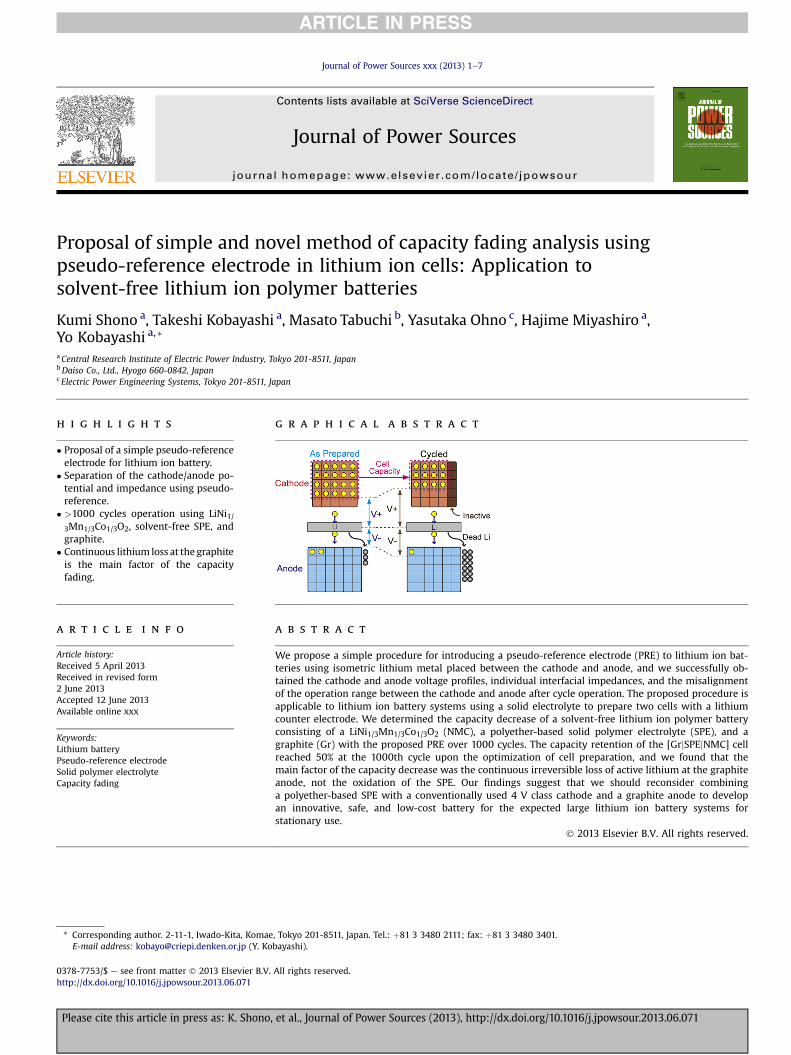
We propose a simple procedure for introducing a pseudo-reference electrode (PRE) to lithium ion bat-teries using isometric lithium metal placed between the cathode and anode, and we successfully ob-tained the cathode and anode voltage profiles, individual interfacial impedances, and the misalignmentof the operation range between the cathode and anode after cycle operation. The proposed procedure isapplicable to lithium ion battery systems using a solid electrolyte to prepare two cells with a lithiumcounter electrode. We determined the capacity decrease of a solvent-free lithium ion polymer batteryconsisting of a LiNi1/3Mn1/3Co1/3O2 (NMC), a polyether-based solid polymer electrolyte (SPE), and agraphite (Gr) with the proposed PRE over 1000 cycles. The capacity retention of the [GrjSPEjNMC] cellreached 50% at the 1000th cycle upon the optimization of cell preparation, and we found that themain factor of the capacity decrease was the continuous irreversible loss of active lithium at the graphiteanode, not the oxidation of the SPE. Our findings suggest that we should reconsider combininga polyether-based SPE with a conventionally used 4 V class cathode and a graphite anode to developan innovative, safe, and low-cost battery for the expected large lithium ion battery systems forstationary use.
� 2013 Elsevier B.V. All rights reserved.
, Tokyo 201-8511, Japan. Tel.: þ81 3 3480 2111; fax: þ81 3 3480 3401.bayashi).
All rights reserved.
et al., Journal of Power Sources (2013), http://dx.doi.org/10.1016/j.jpowsour.2013.06.071
K. Shono et al. / Journal of Power Sources xxx (2013) 1e72
1. Introduction
The application of lithium ion batteries has now begin toextend from mobile use to EV or stationary use. For such largesystems, an operation life much longer than that of mobile systemsis required. Thus, a complete understanding of the capacity fadingmechanism of lithium ion batteries is important for the develop-ment of such long-life battery systems. Monitoring the voltage ofthe cell during charge and discharge is a basic approach to under-standing electrode reactions inside the cell. However, as the anodematerials in most lithium ion batteries have a potential slope, wecannot easily obtain the accurate potential of each electrode duringoperation.
The introduction of a reference electrode with a stable potentialis a useful approach tomonitoring the potential of each electrode inlithium ion cells [1e4]. However, the configuration of such cellsdesigned to obtain a suitable reference electrode performance hasnot yet been optimized for the simple and long-term operation ofthe cells. One novel method of optimizing the configuration is toapply a lithium alloy material with a sufficiently fine (25 mmdiameter) reference electrode [3]. Previous studies have success-fully shown changes in the area specific impedance (ASI), themisalignment of electrode-capacity windows, and changes in theAC impedance during storage [5].
Our objective is to apply a solvent-free solid polymer electrolyte(SPE) in a lithium ion cell system [6,7]. The thickness of the SPEsheet used is 50 mm owing to its relatively low lithium ion con-ductivity. Therefore, we cannot use the so-called “beaker cell”because it requires a long electrolyte distance between electrodes.Furthermore, it is difficult to introduce the above-mentioned finereference electrode into our system because of concerns regardinginhomogeneous current flow and the insufficient mechanicalstrength of the applied SPE. The distribution of current flow in theSPE requires stricter homogeneity than that in a liquid electrolytebecause of the low lithium ion conductivity and immobility ofthe SPE.
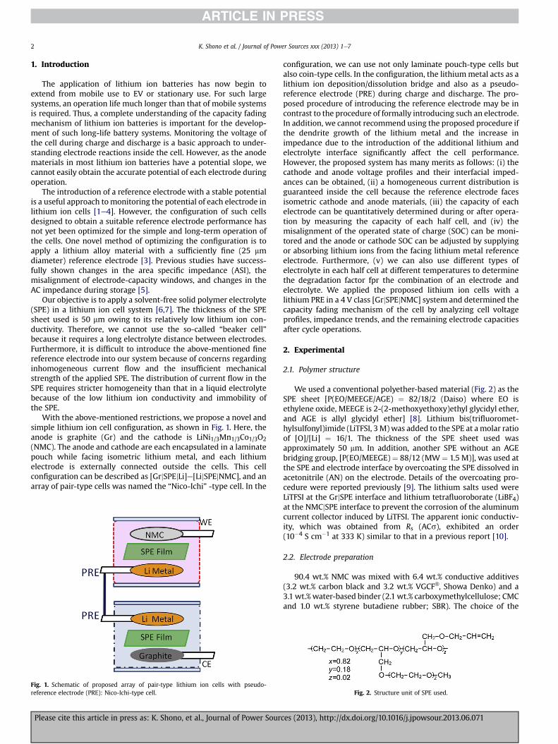
With the above-mentioned restrictions, we propose a novel andsimple lithium ion cell configuration, as shown in Fig. 1. Here, theanode is graphite (Gr) and the cathode is LiNi1/3Mn1/3Co1/3O2(NMC). The anode and cathode are each encapsulated in a laminatepouch while facing isometric lithium metal, and each lithiumelectrode is externally connected outside the cells. This cellconfiguration can be described as [GrjSPEjLi]e[LijSPEjNMC], and anarray of pair-type cells was named the “Nico-Ichi” -type cell. In the
Fig. 1. Schematic of proposed array of pair-type lithium ion cells with pseudo-reference electrode (PRE): Nico-Ichi-type cell.
Please cite this article in press as: K. Shono, et al., Journal of Power Sour
configuration, we can use not only laminate pouch-type cells butalso coin-type cells. In the configuration, the lithiummetal acts as alithium ion deposition/dissolution bridge and also as a pseudo-reference electrode (PRE) during charge and discharge. The pro-posed procedure of introducing the reference electrode may be incontrast to the procedure of formally introducing such an electrode.In addition, we cannot recommend using the proposed procedure ifthe dendrite growth of the lithium metal and the increase inimpedance due to the introduction of the additional lithium andelectrolyte interface significantly affect the cell performance.However, the proposed system has many merits as follows: (i) thecathode and anode voltage profiles and their interfacial imped-ances can be obtained, (ii) a homogeneous current distribution isguaranteed inside the cell because the reference electrode facesisometric cathode and anode materials, (iii) the capacity of eachelectrode can be quantitatively determined during or after opera-tion by measuring the capacity of each half cell, and (iv) themisalignment of the operated state of charge (SOC) can be moni-tored and the anode or cathode SOC can be adjusted by supplyingor absorbing lithium ions from the facing lithium metal referenceelectrode. Furthermore, (v) we can also use different types ofelectrolyte in each half cell at different temperatures to determinethe degradation factor fpr the combination of an electrode andelectrolyte. We applied the proposed lithium ion cells with alithium PRE in a 4 V class [GrjSPEjNMC] system and determined thecapacity fading mechanism of the cell by analyzing cell voltageprofiles, impedance trends, and the remaining electrode capacitiesafter cycle operations.
2. Experimental
2.1. Polymer structure
We used a conventional polyether-based material (Fig. 2) as theSPE sheet [P(EO/MEEGE/AGE) ¼ 82/18/2 (Daiso) where EO isethylene oxide, MEEGE is 2-(2-methoxyethoxy)ethyl glycidyl ether,and AGE is allyl glycidyl ether] [8]. Lithium bis(trifluoromet-hylsulfonyl)imide (LiTFSI, 3M)was added to the SPE at amolar ratioof [O]/[Li] ¼ 16/1. The thickness of the SPE sheet used wasapproximately 50 mm. In addition, another SPE without an AGEbridging group, [P(EO/MEEGE)¼ 88/12 (MW ¼ 1.5 M)], was used atthe SPE and electrode interface by overcoating the SPE dissolved inacetonitrile (AN) on the electrode. Details of the overcoating pro-cedure were reported previously [9]. The lithium salts used wereLiTFSI at the GrjSPE interface and lithium tetrafluoroborate (LiBF4)at the NMCjSPE interface to prevent the corrosion of the aluminumcurrent collector induced by LiTFSI. The apparent ionic conductiv-ity, which was obtained from Rs (ACs), exhibited an order(10�4 S cm�1 at 333 K) similar to that in a previous report [10].
2.2. Electrode preparation
90.4 wt.% NMC was mixed with 6.4 wt.% conductive additives(3.2 wt.% carbon black and 3.2 wt.% VGCF�, Showa Denko) and a3.1 wt.%water-based binder (2.1 wt.% carboxymethylcellulose; CMCand 1.0 wt.% styrene butadiene rubber; SBR). The choice of the
Fig. 2. Structure unit of SPE used.
ces (2013), http://dx.doi.org/10.1016/j.jpowsour.2013.06.071

K. Shono et al. / Journal of Power Sources xxx (2013) 1e7 3
CMC/SBR binder with a 4 V cathode may be unconventional.However, it improved the cycle performance in the SPE system. Theobtained results are reported in detail elsewhere [11]. A similarimprovement in cycle performance using a liquid electrolyte wasreported by other groups [12]. A mixed slurry was pasted onaluminum foil. The slurry consisted of 95.1 wt.% graphite wasmixedwith 1.9 wt.% VGCF� and 2.9 wt.% water-based binder (1.9 wt.% CMCand 1.0 wt.% SBR). The mixed slurry was pasted on electrolyticcopper foil. After sufficient drying for over 10 h at 373 K, followedby pressing and cutting (16 mm f ¼ 2 cm2) of electrodes, theelectrodes were introduced into a glove box (MIWA MFG Co., Ltd.,H2O < 0.1 ppm, O2 < 0.4 ppm). Then, 10 wt.% SPE in AN wasovercoated on the electrodes and dried at 353 K for over 10 h invacuum.
2.3. Cell preparation and operation
SPE-overcoated NMC or graphite was placed facing the lithiummetal (Honjo Metal, 0.3 mm t, 16 mm f) through the 50 mm SPEsheet (20 � 20 mm2). The cell was encapsulated in an Al laminatepouch (60� 110mm2) at 373 Kusing a handy laminator in the glovebox. The handy laminator used was modified from that used forstationery. In the case of the Nico-Ichi-type cell, each lithiumelectrode was connected through the current collector, as shown inFig. 1, and used as a pseudo-reference electrode.
The Nico-Ichi-type cell consisting of [GrjSPEjLi]e[LijSPEjNMC]was operated between 2.5 and 4.2 V. A normal lithium ion cellconsisting of [GrjSPEjNMC] was also prepared for reference. Theprepared cells were initially operated at a rate of C/24 for twocycles as formation cycles. Then, they were cycled in a protocolof (C/8 for two cycles and C/2 for 48 cycles) � n loops. Theoperation temperature was 333 K. The voltage profiles ofgraphite and NMC were monitored using a lithium PRE duringcharge and discharge. The active material weight ratio ofgraphite to NMC was approximately 1:2. The reversible capac-ities of graphite and NMC using a lithium counter electrode were340 mAh g�1 (between 0 and 2.5 V) and 150 mAh g�1 (between2.7 and 4.2 V), respectively. Therefore, the reversible capacity ofgraphite was designed to be approximately 13% larger than thatof NMC.
The AC impedance of the Nico-Ichi-type cell was measured atthe end of the charge at C/8 every 50 cycles. As the reference (RE2 inVMP) was connected to the lithium pseudo-reference electrode, wecould simultaneously obtain the impedance profiles of [WE-PRE]for the NMC cathode, [CE-PRE] for the graphite anode, and [WE-CE] for the full cell. Here, note that the obtained impedance pro-files include the interfacial impedance at LijSPE because we use theisometrically facing lithium metal as a reference.
2.4. SOC adjustment during cycle operations
In the lithium ion cell, the misalignment of the electrode-capacity window was reported as one of the factors thatdecrease the cell capacity [3,5,13e16]. The misalignment is derivedfrom the irreversible loss of active lithium ions, such as through SEIformation and/or the preferential loss of the active material ateither electrode. To determine the main factor causing themisalignment, we continuously monitored the voltage of thecathode at the end of discharge, VCde, at a fixed point and adjustedit to the initial value in each capacity measurement cycle (every 50cycles) using the lithium PRE. In this case, because VCde increasedwith the number of cycles, an insufficient number of lithium ionswere supplied (discharge for the cathode) from the referenceelectrode.
Please cite this article in press as: K. Shono, et al., Journal of Power Sourc
2.5. Electrode capacity measurement after cycle operations
After the cycle operations, the two lithium electrodes in theNico-Ichi-type cell were disconnected at the end of discharge (2.5 Vfor the full cell) at the rate of C/8 with 4 h constant-voltage holding,and the capacity of each electrode was determined using thelithium counter electrode. The [LijSPEjNMC] cell was operatedstarting from discharge to 2.7 V to determine the remaining ca-pacity of the cathode, and its reversible capacity was determined atvoltages between 2.7 and 4.2 V at C/8. In the same manner, the[LijSPEjGr] cell was operated starting from deintercalation to 2.5 V,and its reversible capacity was determined at voltages between0 and 2.5 V at C/8.
3. Results and discussion
3.1. Initial performance of lithium ion cells with pseudo-referenceelectrode
As mentioned above, we can monitor the cathode and anodevoltage profiles separately by introducing a pseudo-referenceelectrode (PRE). Fig. 3 shows the lithium ion full cell voltage andthe cathode and anode individual voltage profiles of the Nico-Ichi-type [GrjSPEjLi]e[LijSPEjNMC] cell at C/8. The bottom axis isdescribed on the basis of cathode capacity. We can determine theend of the charge and discharge voltages of each electrode, asshown in Fig. 3. The charge capacity is limited by the increase incathode voltage, whereas the discharge capacity is limited by theincrease in anode voltage.
Fig. 4 shows the impedance profiles of the full lithium ion celland the cathode and anode in the Nico-Ichi-type cell at the end ofcharge. From the comparison between the profiles of the full celland each electrode, we could assign the large semicircle in the low-frequency region (R2: 12 Hz) in Fig. 4(a) to the interfacial imped-ance at SPEjNMC and the small semicircle in the high-frequencyregion (R1: 1.3 kHz) to the interfacial impedance at GrjSPE. TheWarburg impedance observed in the full cell can be assigned to thecathode on the basis of the length of the diffusion part. Here, notethat LijSPE interfacial impedance is included in Fig. 4. For example,the semicircle in the high-frequency region in [LijSPEjNMC](Fig. 4(b)) overlaps with the LijSPE interfacial impedance, andanother semicircle in the high-frequency region is also derivedfrom NMCjSPE. The corresponding small semicircle was discussedin a previous report and assigned to the SEI component [17]. Todistinguish between these semicircles, we prepared a symmetrical[NMCjSPEjNMC] cell by disassembling two half cells using a lithiumcounter electrode in the charged state and reassembling twocharged NMCs. The obtained results will be discussed in detailelsewhere.
3.2. SOC adjustment using lithium pseudo-reference electrode
Wehave reported the improvement in cathode reversibilitywiththe SPE [7,18,19]. However, the lithium ion full cell (using a graphiteanode) cycle performance has been found to be inferior to that usingthe lithium counter electrode [9]. To clarify the reason for the ca-pacity decrease, we compared the capacity retention process underthe following two conditions. We prepared two cells with thepseudo-reference electrode. In one cell, the cathode SOC wasadjusted every 50 cycles. Fig. 5(a) shows the change in the voltage atthe end of cathode discharge (VCde) of the cell with PRE. VCdeincreased from 3.54 V (1st) to 3.63 V (50th) after 50 cycles. Afterthat, the counter electrode was connected to the lithium PRE,and the cathode was discharged (to supply lithium ions to thecathode) in the initial state (3.54 V). After the SOC adjustment, the
es (2013), http://dx.doi.org/10.1016/j.jpowsour.2013.06.071

Fig. 3. Cell and individual voltage variations of Nico-Ichi-type cell. [GrjSPEjLi][LijSPEjNMC] at 333 K, C/8.
K. Shono et al. / Journal of Power Sources xxx (2013) 1e74
experimentwas restarted from the51st cyclewithVCde¼ 3.53V. Thecomparison of the capacity retention process of the cells with orwithout the SOC adjustment is shown in Fig. 5(b). The recovery ofthe capacity was observed in the cell with the SOC adjustment,whereas a monotonic capacity decrease was observed in the cellwithout the SOC adjustment. The recovery of the capacity by the
Fig. 4. AC impedance profiles of full cell (Nico-Ichi-type), and each electrode interfacialimpedance at the end of charge. (a): [Gr|SPE|Li][Li|SPE|NMC], (b): [Li|SPE|NMC], (c): [Li|SPE|Gr], and (d): [Li|SPE|Li].
Please cite this article in press as: K. Shono, et al., Journal of Power Sour
SOC adjustment strongly indicates that the irreversible loss of activelithium ions rather than the loss of the active cathodematerial is thedominant factor causing the capacity decrease during cycle opera-tions. In other words, an irreversible loss of lithium due to
Fig. 5. (a) Variation of the voltage of cathode of the cell at the end of discharge and (b)capacity retention of full cells with and without SOC adjustment.
ces (2013), http://dx.doi.org/10.1016/j.jpowsour.2013.06.071

K. Shono et al. / Journal of Power Sources xxx (2013) 1e7 5
continuous SEI formation occurs at the graphite anode. Similarphenomena have been reported in a liquid electrolyte system withLiNi0.8Co0.1Al0.1O2 [5], LiNi1/3Mn1/3Co1/3O2 [13], LiFePO4 [14,15] orLiMn2O4 [16]with graphite.Wehave also reported a shift to a higherSOC in a mixture cathode (LiMn2O4/LiNi0.8Co0.15Al0.05O2) with agraphite system [20]. In general, a stable SEI is formed at the anodeby the reduction of liquid electrolyte components such as EC oradditives such as vinylene carbonate (VC). However, we used theSPE instead of a liquid electrolyte in our system; thus, the formed SEImight not have been very stable because there was no carbonateester such as EC or VC to form a stable SEI in the SPE structure.
3.3. Long cycle operation with pseudo-reference electrode
As mentioned above, we observed the individual voltage pro-files and impedances of the cathode and anode, and followed theshift in SOC by monitoring the voltage of the cathode at the end ofdischarge. Then, we attempted to observe the long cycle perfor-mance of the capacity decrease with an optimized cell preparationprocess using the Nico-Ichi-type cell. Fig. 6(a) shows the capacityretention of a 1200-cycle operation with and without the pseudo-reference electrode (PRE). Although a slightly higher capacity wasobserved in the normal cell owing to its lower internal impedance,there was no significant difference in cycle performance betweenthe normal and Nico-Ichi-type cells. This indicates that the intro-duction of lithium metal between the cathode and anode has littleeffect on cycle life. However, a shift to a high SOC in the cathode isstill observed in Fig. 6(b).
Another important factor causing the degradation of cell per-formance is the increase in internal impedance. To determine thedegradation element in the cell, we monitored the change inimpedance with the number of cycles using the Nico-Ichi-type cell,as shown in Fig. 7. The equivalent circuits used for the fitting of theresults are also shown in Fig. 7(d). The change in the impedance
Fig. 6. (a) Cycle performance of full cells with and without PRE, and (b) voltage ofcathode of cell at the end of discharge with PRE.
Please cite this article in press as: K. Shono, et al., Journal of Power Sourc
components with the number of cycles is shown in Fig. 8. R2components, which could be attributed to the NMCjSPE interface,clearly increase with the number of cycles. This indicates that theincrease in cell impedance with the number of cycles is due to theNMCjSPE interface, probably as a result of the partial oxidation ofthe SPE. The decrease in Rs in [LijSPEjNMC] can be explained by thedecrease in the molecular weight of the SPE film due to theoxidation at the NMCjSPE interface, because Rs in [LijSPEjNMC]decreased with the number of cycles and that in [LijSPEjGr] hardlychanged. Details of the change in the molecular weight of the SPEduring the cycle operation will be discussed elsewhere [11]. R1 in[LijSPEjNMC] increased with the number of cycles. R1 consisted ofthe high-frequency semicircle of NMC [17] and the interfacialimpedance at the LijSPE interface. Therefore, we cannot yet deter-mine the reasons for the increase in R1 in [LijSPEjNMC] at present.
On the other hand, the interfacial impedance in [LijSPEjGr] didnot change significantly within 1200 cycles. The reported chargetransfer impedance between the second and first stages, whichcorresponded to our measurement region, also did not significantlychange [21]. However, continuous SEI formation occurred at theinterface, which led to the increase in interfacial impedance, asmentioned above. We measured the AC impedance between200 kHz and 50 mHz. However, we need to obtain a much lowerfrequency for observing the change in diffusion impedance in detail.
3.4. Determination of degradation factor
After the 100-cycle and 1500-cycle operations of the Nico-Ichi-type cells, we compared the capacity of each electrode and themisalignment of the electrode-capacity window between the cath-ode and anode, as shown in Fig. 9. The full scale of the x-axis (0e
Fig. 7. Variations in AC impedance with number of cycles at the end of charge in (a)[GrjSPEjLi]e[LijSPEjNMC], (b) [LijSPEjMMC], (c) [LijSPEjGr], and (d) equivalent circuitsused for the fitting.
es (2013), http://dx.doi.org/10.1016/j.jpowsour.2013.06.071

Fig. 8. Impedance variation of each component.
K. Shono et al. / Journal of Power Sources xxx (2013) 1e76
200 mAh g�1 for the cathode, and 0e400 mAh g�1 for the anode) isplotted by considering the loaded cathode/anode weight ratio (2/1)and each reversible capacity. The misalignment of the cathode- andanode-capacity windows is quantitatively reflected in the experi-mental results below. The reversible capacities of the cathode andanode are an indicator of the compatibility of the cathode and anodewith the SPE. On the other hand, the misalignment of the electrode-capacity window, which is specifically the decrease in usable ca-pacity due to the shift in the operated SOC, is an indicator of theirreversible loss of active lithium ions in operation, as mentionedabove [3,5,13e17]. Table 1 and Fig. 9 show a summary of the cathode
Fig. 9. Electrode capacity and misalignment of electrode
Please cite this article in press as: K. Shono, et al., Journal of Power Sour
reversible capacity (Crev), the shifted capacity from the 2.5 V full celldisassembly (Cshift denoted by :), the anode reversible capacity(Arev), the shifted capacity of the anode (Ashift), and the full-cellreversible capacity (Trev) after formation, 100 cycles, and 1500 cy-cles. Here, the cathode reversible capacity (Crev) was estimated in thevoltage range between 3.0 and 4.2 V. On the other hand, the full cellwas operated between 2.5 and 4.2 V; thus, the actual operatedcathode capacitywas slightly larger than Crev, because the cathode inthe full cell was charged over 4.2 V. Then, we defined the additionalcathode capacity (C>4.2 V denoted by7). The observed voltage of thecathode at the end of charging in the full cell was 4.25 V(7 ¼ 5 mAh g�1) at the formation and after 100 cycles, and 4.30 V(7 ¼ 10 mAh g�1) after 1500 cycles.
The reversible capacity of the cell (Trev) decreased from137 mAh g�1 (formation) to 121 mAh g�1 (100 cycles) as calculatedfrom the cathode weight. However, the reversible capacity of thecathode (Crev) exhibited no significant change (decreased capacity,Cdeg denoted by ; ¼ 2 mAh g�1). Although the anode capacitydecreased by 5 mAh g�1 after 100 cycles, the decrease correspondsto only 2.5 mAh g�1 for the full cell, because the active materialweight ratio of graphite to NMC is approximately 1:2. This indicatesthat the capacity decrease of the cell could not be explained by onlythe capacity decrease of the electrodes. Here, the open circuit po-tential (OCP) of the cathode after disconnecting the full cell at 2.5 Vincreased from 3.67 to 3.70 V owing to the irreversible loss oflithium at the graphite anode. The loss of active lithium ions isreflected in the shifted capacity of the cathode (Cshift denotedby :), as mentioned previously. Note that the calculated cathodeoperated capacity, Crev � Cshift þ C>4.2 V (6þ7 ¼ 120 mAh g�1),could almost explain the reversible capacity (Trev¼ 121mAh g�1) ofthe full cell. Therefore, the shift of the cathode due to the irre-versible loss of lithium at the anode is a dominant factorcausing the capacity decrease of the full cell after 100 cycles.Similarly, the reversible capacity of the full cell after 1500cycles (Trev ¼ 62 mAh g�1) could almost be explained byCrev � Cshift þ C>4.2 V (6þ7 ¼ 62 mAh g�1). Here, the dominantdegradation factor is still the shift of the cathode (:¼ 69mAh g�1).However, the capacity decrease of the cathode (; ¼ 30 mAh g�1)also contributes to that of the cell. The increase in the voltage of thecathode at the end of charging in the full cell may induce thedecrease in cathode reversible capacity. The capacity decrease ofthe cathode after 1500 cycles may be explained by the increase inthe operation voltage range of the cathode.
-capacity window before and after cycle operation.
ces (2013), http://dx.doi.org/10.1016/j.jpowsour.2013.06.071
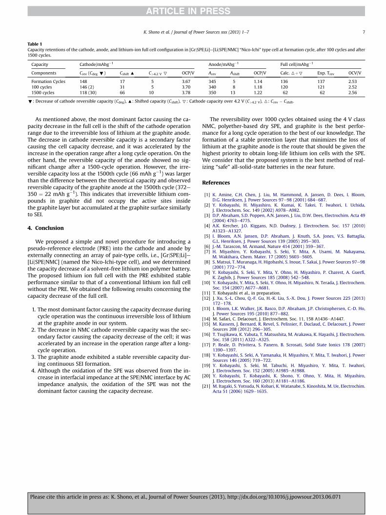
Table 1Capacity retentions of the cathode, anode, and lithium-ion full cell configuration in [GrjSPEjLi]e[LijSPEjNMC] “Nico-Ichi” type cell at formation cycle, after 100 cycles and after1500 cycles.
Capacity Cathode/mAhg�1 Anode/mAhg�1 Full cell/mAhg�1
Components Crev (Cdeg ;) Cshift : C>4.2 V 7 OCP/V Arev Ashift OCP/V Calc. 6þ7 Exp. Trev OCV/V
Formation Cycles 148 17 5 3.67 345 5 1.14 136 137 2.53100 cycles 146 (2) 31 5 3.70 340 8 1.18 120 121 2.521500 cycles 118 (30) 66 10 3.78 350 13 1.22 62 62 2.56
;: Decrease of cathode reversible capacity (Cdeg), :: Shifted capacity (Cshift), 7: Cathode capacity over 4.2 V (C>4.2 V), 6: Crev � Cshift.
K. Shono et al. / Journal of Power Sources xxx (2013) 1e7 7
As mentioned above, the most dominant factor causing the ca-pacity decrease in the full cell is the shift of the cathode operationrange due to the irreversible loss of lithium at the graphite anode.The decrease in cathode reversible capacity is a secondary factorcausing the cell capacity decrease, and it was accelerated by theincrease in the operation range after a long cycle operation. On theother hand, the reversible capacity of the anode showed no sig-nificant change after a 1500-cycle operation. However, the irre-versible capacity loss at the 1500th cycle (66 mAh g�1) was largerthan the difference between the theoretical capacity and observedreversible capacity of the graphite anode at the 1500th cycle (372e350 ¼ 22 mAh g�1). This indicates that irreversible lithium com-pounds in graphite did not occupy the active sites insidethe graphite layer but accumulated at the graphite surface similarlyto SEI.
4. Conclusion
We proposed a simple and novel procedure for introducing apseudo-reference electrode (PRE) into the cathode and anode byexternally connecting an array of pair-type cells, i.e., [GrjSPEjLi]e[LijSPEjNMC] (named the Nico-Ichi-type cell), and we determinedthe capacity decrease of a solvent-free lithium ion polymer battery.The proposed lithium ion full cell with the PRE exhibited stableperformance similar to that of a conventional lithium ion full cellwithout the PRE. We obtained the following results concerning thecapacity decrease of the full cell.
1. Themost dominant factor causing the capacity decrease duringcycle operation was the continuous irreversible loss of lithiumat the graphite anode in our system.
2. The decrease in NMC cathode reversible capacity was the sec-ondary factor causing the capacity decrease of the cell; it wasaccelerated by an increase in the operation range after a long-cycle operation.
3. The graphite anode exhibited a stable reversible capacity dur-ing continuous SEI formation.
4. Although the oxidation of the SPE was observed from the in-crease in interfacial impedance at the SPEjNMC interface by ACimpedance analysis, the oxidation of the SPE was not thedominant factor causing the capacity decrease.
Please cite this article in press as: K. Shono, et al., Journal of Power Sourc
The reversibility over 1000 cycles obtained using the 4 V classNMC, polyether-based dry SPE, and graphite is the best perfor-mance for a long cycle operation to the best of our knowledge. Theformation of a stable protection layer that minimizes the loss oflithium at the graphite anode is the route that should be given thehighest priority to obtain long-life lithium ion cells with the SPE.We consider that the proposed system is the best method of real-izing “safe” all-solid-state batteries in the near future.
References
[1] K. Amine, C.H. Chen, J. Liu, M. Hammond, A. Jansen, D. Dees, I. Bloom,D.G. Henriksen, J. Power Sources 97e98 (2001) 684e687.
[2] Y. Kobayashi, H. Miyashiro, K. Kumai, K. Takei, T. Iwahori, I. Uchida,J. Electrochem. Soc. 149 (2002) A978eA982.
[3] D.P. Abraham, S.D. Poppen, A.N. Jansen, J. Liu, D.W. Dees, Electrochim. Acta 49(2004) 4763e4775.
[4] A.K. Kercher, J.O. Kiggans, N.D. Dudney, J. Electrochem. Soc. 157 (2010)A1323eA1327.
[5] I. Bloom, A.N. Jansen, D.P. Abraham, J. Knuth, S.A. Jones, V.S. Battaglia,G.L. Henriksen, J. Power Sources 139 (2005) 295e303.
[6] J.-M. Tarascon, M. Armand, Nature 414 (2001) 359e367.[7] H. Miyashiro, Y. Kobayashi, S. Seki, Y. Mita, A. Usami, M. Nakayama,
M. Wakihara, Chem. Mater. 17 (2005) 5603e5605.[8] S. Matsui, T. Muranaga, H. Higobashi, S. Inoue, T. Sakai, J. Power Sources 97e98
(2001) 772e774.[9] Y. Kobayashi, S. Seki, Y. Mita, Y. Ohno, H. Miyashiro, P. Charest, A. Guerfi,
K. Zaghib, J. Power Sources 185 (2008) 542e548.[10] Y. Kobayashi, Y. Mita, S. Seki, Y. Ohno, H. Miyashiro, N. Terada, J. Electrochem.
Soc. 154 (2007) A677eA681.[11] T. Kobayashi et al., in preparation.[12] J. Xu, S.-L. Chou, Q.-F. Gu, H.-K. Liu, S.-X. Dou, J. Power Sources 225 (2013)
172e178.[13] I. Bloom, L.K. Walker, J.K. Basco, D.P. Abraham, J.P. Christophersen, C.-D. Ho,
J. Power Sources 195 (2010) 877e882.[14] M. Safari, C. Delacourt, J. Electrochem. Soc. 11, 158 A1436eA1447.[15] M. Kassem, J. Bernard, R. Revel, S. Pelissier, F. Duclaud, C. Delacourt, J. Power
Sources 208 (2012) 296e305.[16] T. Tsujikawa, K. Yabuta, T. Matsushita, M. Arakawa, K. Hayashi, J. Electrochem.
Soc. 158 (2011) A322eA325.[17] P. Reale, D. Privitera, S. Panero, B. Scrosati, Solid State Ionics 178 (2007)
1390e1397.[18] Y. Kobayashi, S. Seki, A. Yamanaka, H. Miyashiro, Y. Mita, T. Iwahori, J. Power
Sources 146 (2005) 719e722.[19] Y. Kobayashi, S. Seki, M. Tabuchi, H. Miyashiro, Y. Mita, T. Iwahori,
J. Electrochem. Soc. 152 (2005) A1985eA1988.[20] Y. Kobayashi, T. Kobayashi, K. Shono, Y. Ohno, Y. Mita, H. Miyashiro,
J. Electrochem. Soc. 160 (2013) A1181eA1186.[21] M. Itagaki, S. Yotsuda, N. Kobari, K. Watanabe, S. Kinoshita, M. Ue, Electrochim.
Acta 51 (2006) 1629e1635.
es (2013), http://dx.doi.org/10.1016/j.jpowsour.2013.06.071