PROPOSAL INFORMATION PACKAGE MARS SURVEYOR ‘98 ...
31
NATIONAL AERONAUTICS AND SPACE ADMINISTRATION MARS SURVEYOR ‘98 PARTICIPATING SCIENTIST ANNOUNCEMENT OF OPPORTUNITY PROPOSAL INFORMATION PACKAGE
Transcript of PROPOSAL INFORMATION PACKAGE MARS SURVEYOR ‘98 ...

NATIONAL AERONAUTICS AND SPACE ADMINISTRATION
MARS SURVEYOR ‘98 PARTICIPATING SCIENTIST
ANNOUNCEMENT OF OPPORTUNITY
PROPOSAL INFORMATION PACKAGE
2
2
TABLE OF CONTENTSpage
1.0 INTRODUCTION 31.1 Document Overview 31.2 Mars Surveyor Program 31.3 Mars Surveyor ‘98 Operations Management 51.4 MCO Payload Overview 61.5 MPL Payload Overview 7
2.0 MISSION SCIENCE 92.1 Mars Surveyor 1998 Mission Strategy 92.2 Mars Surveyor 1998 Mission Measurement Objectives 10
3.0 MISSION PHASES 1 13.1 Landing Site Adjustment Maneuver 133.2 MCO Orbital Insertion and Aerobraking 133.3 MPL Entry, Descent and Landing 153.4 MPL Landed Operations 153.5 MCO Lander Support Phase 183.6 MCO Mapping Mission 18
4.0 SCIENCE INVESTIGATIONS: MARS CLIMATE ORBITER 2 14.1 Pressure Modulator Infrared Radiometer (PMIRR) 214.2 Mars Color Imager (MARCI) 24
5.0 SCIENCE INVESTIGATIONS: MARS POLAR LANDER 2 65.1 Mars Descent Imager (MARDI) 265.2 Mars Volatiles and Climate Surveyor (MVACS) 26
5.2.1 Surface Stereo Imager (SSI) 275.2.2 Robotic Arm (RA); Robotic Arm Camera (RAC), Surface Thermal Probe (STP) 275.2.3 Meteorological Package (MET) 285.2.4 Thermal and Evolved Gas Analyzer (TEGA) 295.2.5 Potential Areas of Emphasis for Participating Scientists with MVACS 30
5.3 LIDAR 30

3
3
1.0 INTRODUCTION
1.1 Document Overview
This Proposal Information Package (PIP) document provides information describing the Mars Surveyor 1998Mission, which includes activities associated with both the Mars Climate Orbiter (MCO) and the Mars PolarLander (MPL). This PIP is provided in support of the Mars Surveyor ‘98 (MS’98) Announcement ofOpportunity for Participating Scientists (AO 99-OSS-02).
1.2 Mars Surveyor Program
The National Aeronautics and Space Administration (NASA) has initiated a long-term systematic program ofMars exploration, the Mars Surveyor Program (MSP). The highest priority scientific objectives of this programare to:
• Search for evidence of past or present life;• Understand the climate and volatile history of Mars;• Assess the nature and inventory of resources on Mars.
The common thread of these objectives is water: past and present sources and sinks; exchanges betweensubsurface, surface and atmospheric reservoirs; and the change of volatiles over time.
The goal of the MSP is to carry out low-cost missions, each of which provides important, focused, scientificreturn, and which will in sum constitute a major element of the scientific exploration of Mars. A series of lander
4
4
and orbiter spacecraft are being launched at each favorable Mars launch opportunity, which occur approximatelyevery 26 months. In 1997 the MSP launched the Mars Global Surveyor (MGS), which together with the launchof the Discovery Program’s Mars Pathfinder lander, initiated the new era of Mars exploration.
In the 1998-1999 launch opportunity, the MSP successfully launched the following spacecraft, which are now inflight to Mars:
• Mars Climate Orbiter (MCO) launched on December 11, 1998• Mars Polar Lander (MPL) launched on January 3, 1999.
The Mars Polar Lander also carries two New Millennium Program (NMP) microprobes as the Deep Space 2(DS2) Mission. These probes will separate from MPL prior to its entry into the Martian atmosphere, then fallthrough the atmosphere (without parachutes or rockets to slow their entry) and crash into the surface, with theprobe forebodies penetrating up to a meter deep into the Mars surface. A Science Team has been previouslyselected for the DS2 mission and no participation is solicited here. However, the short-lived DS2 probes will belocated approximately 100 km further north (equatorward) of the MPL touchdown point and will themselvessearch for the presence of subsurface water ice and attempt to characterize subsurface soil thermal properties.Thus, complementary data will be obtained by the DS2 and MPL surface packages (and by MCO and MGS).
Future missions will culminate in the return of samples of Martian rocks and soil to Earth. The focus of theMS’98 element of the MSP is to advance our understanding of the volatile and climate history of Mars throughsystematic mapping of the Mars seasonal cycles of weather, dust, water and carbon dioxide by remote sensingfrom orbit and through exploration in situ at a landed site on the layered terrain near the Martian south pole.
5
5
1 .3 Mars Surveyor ‘98 Operations Management
The Mars Surveyor Program is managed by the Jet Propulsion Laboratory (JPL), California Institute ofTechnology, for NASA’s Office of Space Sciences. A JPL development project oversaw the design, build, andtesting of the MCO and MPL by Lockheed-Martin Astronautics (LMA) in their Denver, Colorado, facilities,launch of the spacecraft onboard separate Boeing Delta 7425 launch vehicles from the Cape Canaveral Air ForceStation in Florida, and operation of the spacecraft during the first month of flight, which saw successfuldeployment of solar arrays, establishment of telecommunication links and spacecraft flight control, and executionof trajectory course correction maneuvers that corrected for launch bias and injection errors.
Now in mid-cruise, MCO and MPL are operated by a spacecraft flight team at LMA and flight operations teamsat JPL managed by the Mars Surveyor Operations Project (MSOP). This JPL-LMA team is also responsible foroperation of MGS, even as the team assists development of future spacecraft elements of the Mars SurveyorProgram. The MSOP also funds and manages operations by the science investigations and the initial analysis ofdata returned by the spacecraft and their scientific instruments.
Science investigations on the Mars Climate Orbiter and Mars Polar Lander will largely be conducted remotelythrough the principal investigator’s home institution. This includes both commanding of the science instrumentsand analysis of the returned instrument engineering and scientific data.

6
6
1.4 MCO Payload Overview
The Mars Climate Orbiter carries the following science instruments:
• Pressure Modulator Infrared Radiometer (PMIRR);• Mars Color Imager (MARCI).
PMIRR is essentially a build-to-print copy of the atmosphere sounder and polar radiative balance mapper flownpreviously on Mars Observer. PMIRR will provide vertical profiles of temperature, dust and water vapor overthe planet each day, in addition to monitoring reflected sunlight and thermal infrared radiance. MARCI consistsof two camera systems sharing common components. The Wide Angle camera will provide daily synopticmosaics of the Mars atmosphere and surface, including observations at ultraviolet wavelengths, while theMedium Angle camera will image the surface in several visible and near-infrared bands at moderate spatialresolution (40-m at nadir).
The instruments are described in more detail in separate sections. Both PMIRR and MARCI are mounted so thattheir (vertical) z-axis is nadir pointed, even though the spacecraft z-axis is tilted somewhat to minimize gravitygradient torques and fuel usage for station-keeping on orbit. PMIRR has a two-axis scan mirror that enables it tolook anywhere in a quadrant below the spacecraft and from the aft limb to the (“sunward”) side limb. MARCIhas no scanning capability; instead MARCI utilizes a “push-frame” approach in which adjacent spectral coatingbands on its charged-coupled detectors (CCDs) are overlapped by MCO’s motion along the spacecraft ground-track and by appropriate timing of image acquisition.
MCO also carries a Radio Relay (UHF) for communication with surface landers, including the Mars PolarLander and potentially the MSP ‘01 Lander now being built. Unlike MGS, MCO does not carry an ultrastableoscillator (USO) and so no radio science investigation was selected. However, entry occultations, as MCOdisappears behind the planet, may be candidates for analysis.

7
7
An additional source of engineering data can provide information about the Martian upper atmosphere. Duringaerobraking, current plans are to return 1-second samples of the MCO accelerometer output during eachaeropass, as the orbiter dips into the upper atmosphere of Mars (with periapsis likely to be 110 km altitude) toslow its speed and thereby lower its apoapsis, ultimately achieving a nearly circular and polar orbit. Theseaccelerometer measurements can be related to atmospheric density and temperature of the upper atmosphere.
1.5 MPL Payload Overview
The Lander payload includes, by design and selection, an integrated suite of instruments, under the auspices of asingle Principal Investigator and his Co-Investigators:
• Mars Volatiles and Climate Surveyor (MVACS)• Surface Stereo Imager (SSI) with Magnetic Targets• Robotic Arm and Robotic Arm Camera (RA, RAC)• Meteorology Package (MET)• Water Vapor and Isotope Tunable Diode Laser (TDL)• Thermal / Evolved Gas Analyzer (TEGA)• Surface Thermal Probe (STP)
and two individually selected instruments:• Mars Descent Imager (MARDI)• LIDAR (with Microphone)
During the Lander's descent to the surface, MARDI will acquire a series of nested images at ever higher spatialresolution, beginning after parachute deployment and heat shield jettison (see below).
8
8
MPL will soft-land on the surface at polar latitudes (74-77S) in the southern hemisphere of Mars, where theMVACS integrated instrument suite, together with a LIDAR experiment provided by the Russia’s Space ResearchInstitute (IKI), will perform landed investigations. The LIDAR will provide the altitudes of low-altitude (< 5km) hazes and clouds using active ranging. It also contains a microphone for exploring the acoustic environmentof Mars. Because of data volume constraints, a typical LIDAR/microphone mode stores for readout and returna ten-second record of the “loudest” (i.e., most detectable) sound detected during a longer sampling period.
MVACS will use its Robotic Arm to: 1) provide access to the surface and subsurface, by trenching into thesurface; 2) emplace the Surface Thermal Probe to characterize heat capacity; 3) use the Robotic Arm Camera toview sidewalls of the trench and to characterize soil samples; and 4) to obtain soil samples for the TEGA. TheSSI will also observe sky brightness and estimate atmospheric column abundances of dust, condensate and watervapor. Water vapor concentration is also measured locally by the atmospheric TDL. Meanwhile, local airtemperatures and winds will be measured by devices located on two meteorological masts, one vertical above theMPL deck and the other slanting down near the (atmospheric) surface layer.
9
9
2.0 MISSION SCIENCE
The Mars Surveyor 1998 Missions were designed, and their payloads selected, to address the science theme"Volatiles and Climate History" on Mars, thereby directly addressing the climate-history and resource themes ofthe Mars Surveyor Program, while supporting the life-on-Mars theme through characterization of climatechange and its evolving impact on the distribution of water.
2.1 Mars Surveyor 1998 Mission Strategy
To address the “Volatiles and Climate History” theme within the programmatic constraints of cost and affordablelaunch capabilities, the Mars Climate Orbiter and Mars Polar Lander Missions pursued the following scientificstrategy:
• Use seasonal and diurnal cycles of Dust, Water and Carbon Dioxide to understand Processes of climatechange over longer time scales;
• Characterize global atmospheric structure and circulation to elucidate roles of Atmospheric Transport
of Volatiles and Dust; • Land on, and explore, a site having Physical Evidence of ancient climates, atmospheric evolution and
more recent, possibly periodic climate change;
• Locate surface Ice Reservoirs and search for local Sub-Surface Ice; • Acquire data needed to validate and extend Model Simulations of climate processes and climate change; • Emphasize Comparative Study of the climates of Earth and Mars and their potential implications for
origin and development of life.

10
10
2.2 Mars Surveyor 1998 Mission Measurement Objectives
Given the scientific strategy outlined above, the major scientific measurement objectives for the Mars SurveyorProgram 1998 Missions are to:
• Systematically observe the thermal structure and dynamics of the global atmosphere and the radiativebalance of the polar regions, thereby providing a quantitative climatology of weather regimes and dailyto seasonal processes;
• Determine the variations with time and space of the atmospheric abundance of dust and of volatile
material (i.e., carbon dioxide and water, both vapor and ice) for one full Martian year; • Identify surface reservoirs of volatile material & dust and observe their seasonal variations;
characterize surface compositional boundaries and their changes with time; search for near-surfaceground ice in the polar regions;
• Explore and quantify the climate processes of dust storm onset and decay, of atmospheric transport of
volatiles and dust, and of mass exchange between the atmosphere, surface and subsurface; • Search for evidence characterizing ancient climates and more recent periodic climate change.

11
11
3.0 Mission Phases
The MCO and MPL spacecraft are now in the second half of their journey to Mars. Key mission events andphases remaining are (see schedule below):
• MPL Site Adjustment Maneuver (SAM) Early September, 1999 • MCO Mars Orbital Insertion (MOI) September 23 • MCO Aerobraking (A/B) Sept. 25 - Nov. 25 • MPL Entry, Descent and Landing (EDL) December 3 • MPL Landed Operations Dec. 3 - Mar. 1, 2000 • MCO Lander Support Phase (LSP) Dec. 3 - Mar. 1, 2000 • MCO Mapping Mission Mar. 1, 2000 - Jan. 15, 2002 • MCO Relay Phase Jan. 15, 2002 - 2003
The mission overview on the next page shows the key milestones, including the arrival of the MS’01 Lander andthe overlapping MGS mapping mission.

12
12
MS’98 MISSION OVERVIEW
Cruise Phase
Launch (12/10-25/98)
TCM-1(12/23-1/10)
TCM-3(7/25-8/5)
TCM-4(9/13-9/24)
MARS CLIMATE ORBITERMCO Mapping Phase
MARS POLAR LANDER
Landed Science Phase
MGS Mapping Phase
S. Spring S. Summer N. Spring N. Summer S. Spring S. Summer
Perihelion(1.38 AU)
Max Earth Range (2.62 AU)
Aphelion(1.67 AU)
Min Earth Range (0.45 AU)
Perihelion (1.38 AU)
Relay
TCM-2(1/24-2/8)
TCM-5 [contingency] andENTRY (12/3-17/99)
Cruise Phase
Launch (1/3-27/99)
TCM-1(1/18-2/11)
TCM-4(11/29-12/13)
TCM-2(2/17-3/13)
TCM-3(10/4-10/18)
ABX 2/15
Aerobraking
(~75 deg S)
MSP ‘01 LanderArrival
MPL Lander Support Phase
MOI (9/23-10/4/99)
Transfer to Mapping Orbit
12/04
‘98 1999 2000 2001
Nov Apr Jul Oct Jan Apr Jul Oct Jan Apr Jul Oct JanJan
2002
Site Adjustment Maneuver
(8/21-9/14)DS-2 µPROBE Arrival (12/3-17/99)
Aerobraking
Relay
TMO 4/10,4/11
MGS

13
13
3.1 Landing Site Adjustment Maneuver
MPL is currently targeted to 75S, 200W with a 2-sigma landing error ellipse approximately 200 km down track(± 100 km, principally north-to-south) and 20 km cross-track (± 10 km, west-to-east). A final target landingsite, located in the target zone 74S-76S; 170W-230W will be selected based on imaging data from past spacecraftmissions (Mariner 9 and Viking) and on preliminary data from the MGS Mars Orbiter Laser Altimeter (MOLA)and Mars Orbiter Camera (MOC). This site will be selected by August, 1999, and a Site Adjustment Maneuvermust be performed in cruise by MPL by early September. The target zone is the most northern (equatorward)part of the south polar layered terrain and is likely to be free of seasonal carbon dioxide frost at the time ofarrival (areocentric longitude Ls = 256). The poleward limit of the target zone is due to atmospheric entryangle (“skip-out”) and entry atmospheric heating constraints.
3.2 MCO Orbital Insertion and Aerobraking
At the present time, no observations by the MARCI or PMIRR are planned during this mission phase, whichfollows Mars approach images to be taken by MARCI in late cruise (~ Sept. 5). PMIRR cannot observe becauseits passive radiator is directed into the flow during each aeropass, and so its radiator door remains in the vent(nearly closed) position to protect the radiator from contamination and from inadvertent solar illuminationduring spacecraft positioning for aerobraking. Accelerometer (engineering) data will be recorded by the LMAspacecraft team and estimates of periapsis density will be reconstructed by the JPL MSOP navigation team. MCOaerobraking will be conducted at a time when observations by the MGS science payload and spacecraft will beroutinely acquired as part of the MGS mapping mission.

14
14
SOLAR PANEL /INSTRUMENTDEPLOYMENTS(L + 20 min)
RADAR GROUNDACQUISITION (ALTITUDE)(L – 50 s)2500 m85 m/s LANDER SEPARATION /
POWERED DESCENT (L – 35 s)1300 m80 m/s
TOUCHDOWN2.5 m/s
GUIDANCESYSTEMINITIALIZATION(L – 15 min)4600 km5700 m/s
TURN TOENTRYATTITUDE(L – 12 min)3000 km5900 m/s
CRUISE RING SEPARATION / MICROPROBE SEPARATION2300 km6200 m/s
ATMOSPHERIC ENTRY (L – 5 min)125 km6900 m/s
PARACHUTE DEPLOYMENT (L – 2 min)8800 m490 m/s
HEATSHIELD JETTISON (L – 110 s)7500 m250 m/s
RADAR GROUND ACQUISITION(DOPPLER) (L – 36 s)1400 m80 m/s
(L – 10 min)

15
15
3.3 MPL Entry, Descent and Landing
During descent (see above), MPL will not record individual accelerometer readouts, but will record integratedstate position vectors, based on the higher-rate sampling accelerometer measurements. These state positions willnominally be returned during the first hours after landing. The day of landing (Dec. 3, 1999) is designatedSol 0 (a sol is a martian day). MPL will land at ~ 5 a.m., Mars local time.
The Mars Descent Imager (MARDI) will acquire up to a dozen images during descent of MPL, following jettisonof the heat shield at an altitude less than 8 km above the surface. The number of images acquired depends in parton atmospheric conditions at the time of entry, as these conditions (and the final choice of landing target latitude)may cause a somewhat shorter or longer descent time in the atmosphere, with longer times associated with longer(and more poleward) atmospheric flight paths. The quality of images during powered descent, fromapproximately 1 km altitude to the ground, is unknown, as the camera will be looking through rocket plumesfrom three banks of four rocket thrusters each, firing in rapidly pulsed sequences orchestrated by the onboardguidance. Close to the surface, there will also be dust raised up into the atmosphere by the multiple rocketexhausts and thermal plumes impinging the surface.
3.4 MPL Landed Operations
The first few sols (i.e., Mars days) after touchdown of the MPL are devoted to: (1) establishing radiocommunication with the MPL, first through its direct-to-Earth (DTE) telecommunications system with themedium-gain antenna, and then via relay through the MCO; and (2) returning: a) the MARDI data, b) stowedand unstowed Surface Stereo Imager elevation scans, c) descent and landed engineering data, and d) initialenvironmental data acquired by the MET and LIDAR instrument suites. Activities scripted for Sol 0 through Sol2 are included in the onboard spacecraft sequence. If the relay through MCO is not working, the MPLspacecraft will automatically continue using an onboard contingency sequence which routinely uses the DTE linkwhile continuing to try the MCO relay path. Commanded science sequences are initiated on Sol 2 if operationsare proceeding nominally.
16
16
MPL is a solar-powered lander with a relatively small battery system. Even though the Sun will be above thehorizon at these southern polar latitudes during the late southern spring and early southern summer seasons whenMPL will be operating on the surface of Mars, the elevation of the Sun changes throughout the day, with theperiod of high Sun (referred to as “day”) being the most optimum period for solar power generation and thusoperation of the lander and payload. The payload will not normally be operated continuously through the night(i.e., the period when the Sun is low on the horizon), but hourly observations are anticipated on many nights,subject both to the power required by that day’s operations and the Martian environment, particularly the amountof dust suspended in the atmosphere.
Due to power limitations, the direct-to-Earth (DTE) radio link will be used sparingly, assuming that the MCOorbiter relay is working properly. DTE sessions are planned during the first week of landed operations and,assuming nominal success of the MCO relay path, on a weekly basis thereafter. Later in the mission (> Sol 25),MPL may use a special meteorological observational sequence where it relies solely on the DTE link for a weekor so, enabling high-frequency observations by MPL and simultaneous observations by MCO. MPL can returndata to, and receive commands from, Earth via the MCO relay. Use of the MCO does introduce latency into theMPL data return, as MPL data is stored onboard the MCO and returned during regularly scheduled downlinksfrom the MCO.
MPL data can also be returned to, but the spacecraft cannot be commanded from, Earth using the MGS MarsRelay. Also, the battery operated DS-2 probes can return data only through MGS. Given their battery-onlypower (no arrays) and thus finite lifetime, the DS-2 probes have been given priority for the MGS relay, withMCO designated as the primary relay for MPL. The orbit of MCO will be phased such that there will be up tofour UHF relay opportunities between MCO and MPL during prime operating hours of the lander on each sol.
Following nominal return of descent and early landed data, it is anticipated that full science operations willcommence on Sol 2. Key operational sequences to be conducted are: 1) low and high-resolution, monochromaticand multi-spectral panoramas by the SSI of the local landscape; 2) trenching of the Martian soil; 3)

17
17
characterization of the local meteorology and of surface and sub-surface magnetic, thermal and reflectanceproperties; 4) eight TEGA analysis runs, utilizing soil from different depths and possibly different locationswithin the Robotic Arm workspace; 5) characterization of the overhead atmospheric opacity, both as haze and asclouds; 6) exploration of the acoustic environment on Mars (requiring “quiet” listening periods with minimallander payload activity, to prevent masking of uniquely Martian sounds).
Eventually, true sunset will occur at the MPL latitude, in mid-summer. Reduced sunlight impacts both thethermal environment of the lander and generation of power by its solar arrays. Furthermore, both elements maybe adversely affected by atmospheric hazes, whether composed of suspended condensates or dust particles. Whileno explicit account of dust accumulation on the solar arrays has been assumed, the aim is to accomplish the bulkof the Lander activities (e.g., conduct most of the TEGA sample analysis and complete an adequate multi-spectralpanorama of the landscape) within 30 sols of landing. Following the first month of MPL activity, observationswill be designed to capture essential aspects of the seasonal cycle, to improve the spatial resolution of multi-spectral imaging of the landscape, to continue digging deeper into the terrain and to conduct the final TEGAsampling experiment(s). Ultimately, the MPL batteries will fail to be recharged or some component will break,perhaps due to extreme cold, ending the mission. The expected lifetime of MPL operations on the surface ofMars is expected to be approximately 60-90 sols.
The pace and duration of science operational sequences depend critically on the MPL landed power capability,particularly the generating capability of the MPL solar arrays as affected by deployment, orientation(shadowing), spacecraft tilt, and by the variable atmospheric opacity.

18
18
3.5 MCO Lander Support Phase
Following the end of aerobraking, and prior to the landing of MPL on Mars, MCO will essentially be in its near-polar, circular mapping orbit, although the final transfer to mapping orbit may be delayed until after landing andearly operations of MPL on the surface. During this mission phase, MCO will give priority to the relay ofcommands to, and the return of data from, the Mars Polar Lander.
Observations by MARCI may be conducted during this period, contingent upon adequate data volume and thepriority given multi-mission operations activities. Both MARCI and PMIRR are affected by operation of theUHF relay used to communicate with MPL, and there is currently a flight rule which requires that these twoinstruments be off during operation of the UHF relay. MARCI can turn on and off quickly, avoiding the relayperiods when used (up to four per sol), with the relay periods ranging in duration from a few up to 15 minutes,accounting for warm-up of the relay hardware. PMIRR, however, is not easily switched on and off, as it requiresseveral hours for its passively (i.e., radiatively) cooled detector focal plane to reach operating temperatures, andfor the instrument optical path to stabilize at the desired temperature. Thus, no PMIRR operations are planneduntil the MPL no longer needs relay through MCO for extended periods.
3.6 MCO Mapping Mission
MCO will commence its mapping mission on March 1, 2000, and will continue to support MARCI and PMIRRobservations for one Mars year. If MPL landed operations have ended prior to this date, MCO will beginmapping operations earlier, but will continue to support instrument observations until January 15, 2002. ShouldMPL still be operating at the end of February, MPL will revert to the use of its DTE link and possibly to datareturn by the MGS Mars Relay.

19
19
The Mapping Mission orbit will be a nearly frozen orbit, nominally at 405 km altitude. At the end ofaerobraking, the local time of the MCO orbit will be near 5 p.m. By choice of orbital inclination, a “sun-drifting” orbit can be established, in which the mean local solar time of the dayside descending equatorial nodewill “drift” to earlier local times, with much of the mapping mission spent near 4 p.m./4 a.m. local solar time,until Mars is once again near perihelion, when the local time may move as early as 3 p.m./3 a.m. The majorconstraint on the choice of this drift rate is the requirement to have sufficient power to operate PMIRR, as wellas MARCI, at aphelion and to operate the UHF radio relay in early 2002 to support the MS’01 lander surfaceoperations. At present, the major restriction is posed by having MCO at a true local solar time no earlier than 4p.m. at aphelion. (Earlier local times would mean that MCO would not close energy balance daily due to solareclipse by Mars for significant periods.)
The final choice of sun-drift rates and local time variation will depend upon actual performance of the MCOsolar arrays and of orbit evolution during MCO aerobraking.
Originally designed for a 2 p.m. - 2 a.m. orbit, the MCO instruments are affected by restriction to these laterlocal solar times. For PMIRR, there will be less contrast between surface and atmospheric temperatures, whichwill complicate vertical profiling using on-planet (including nadir) views, and there may be more atmosphericcondensates present near the evening terminator, limiting the ability of PMIRR to observe the atmosphere nearthe surface and at the limb. MARCI is more affected, in that it was designed to highlight spectral compositionaldifferences of the surface, which is not easily done at large view angles. Furthermore, the illumination of thelimb-to-limb cross-track MARCI Wide Angle view is less symmetric at late afternoon local times , complicatingthe generation of a daily global mosaic. On the other hand, the planned sun-drift orbit will provide MARCIobservations at earlier local times late in the mapping mission, and the combination of MCO and MGSobservations will provide much better coverage of diurnal variations, which are a significant part of Marsmeteorological variations--much more so than on Earth.
The prolonged MGS aerobraking necessitated by the weakened solar array damaged during deployment soonafter launch has shifted the nominal MGS mapping mission, so that it now overlaps the MCO mapping mission
20
20
(see above). This provides an excellent opportunity for even better space-time coverage of the atmosphere andsurface than could be provided by either spacecraft alone. Furthermore, it permits intercomparison ofinstrument suites to better define instrument and algorithm biases and errors, permitting observations fromdifferent Mars years to be intercompared quantitatively. Of special interest for instrument validation arecontemporaneous, spatially co-incident (to the extent possible) observations by the MGS Thermal EmissionSpectrometer (TES) and Radio Science (RS) investigations with the MCO PMIRR and similar intercomparisonswith the MGS MOC and MCO MARCI.
21
21
4.0 SCIENCE INVESTIGATIONS: MARS CLIMATE ORBITER
4.1 Pressure Modulator Infrared Radiometer (PMIRR)
PMIRR is a nine-channel limb and nadir scanning atmospheric sounder designed to vertically profile atmospherictemperature, dust, water vapor and condensate clouds and to quantify surface radiative balance. PMIRRobserves in a broadband visible channel, calibrated by observations of a solar target mounted on the instrument,and in eight spectral intervals between 6 and 50 µm in the thermal infrared. High spectral discrimination in the6.7 µm water vapor band and in two parts of the 15 µm carbon dioxide bands is achieved by employing pressure(density) modulation cells in front of selected spectral detectors. Adequate signal-to-noise in these channels isensured through the placement of their detectors on a cold focal plane assembly cooled to 80 K by a passiveradiative cooler. The reflight of PMIRR is a joint enterprise of JPL, Oxford University and of the RussianSpace Research Institute (IKI, as part of the “Mars Together” Program). The PMIRR Principal Investigator isDr. Daniel McCleese (JPL/Caltech); Vasily Moroz (Russia) is Joint Principal Investigator. Table I lists thePMIRR team members selected by NASA and the supporting team members from IKI.
No PMIRR science observations are taken prior to the MCO achieving its mapping orbit, when the PMIRRradiator door is fully opened. Once PMIRR is deployed in the mapping orbit, vertical profiles of atmosphericproperties are constructed from observations in three fields-of-view (FOV) stepped across the limb and onto theplanet using a two-axis scan mirror in front of the primary telescope. Nominally, PMIRR views the aft limb,referenced to the spacecraft, except for the polar regions where it routinely views in and out of the plane of thespacecraft track to quantify the polar surface albedo by observing much of the bi-direction reflectancedistribution function. PMIRR can also view to the side limb, acquiring observations characterized by differentlocal times.
PMIRR is essentially a rebuild of the instrument flown on Mars Observer, with the following significant changes:Deletion of an enriched isotopic mixture for the pressure modulation cell containing carbon dioxide; slightly
22
22
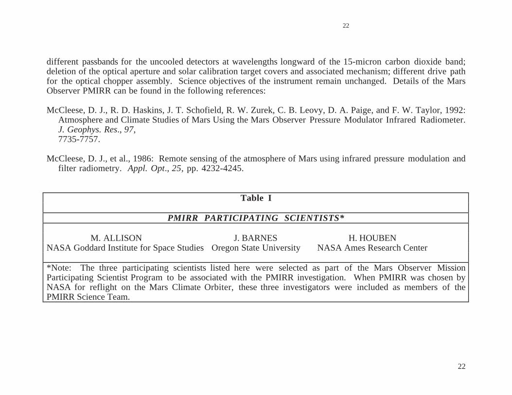
different passbands for the uncooled detectors at wavelengths longward of the 15-micron carbon dioxide band;deletion of the optical aperture and solar calibration target covers and associated mechanism; different drive pathfor the optical chopper assembly. Science objectives of the instrument remain unchanged. Details of the MarsObserver PMIRR can be found in the following references:
McCleese, D. J., R. D. Haskins, J. T. Schofield, R. W. Zurek, C. B. Leovy, D. A. Paige, and F. W. Taylor, 1992:Atmosphere and Climate Studies of Mars Using the Mars Observer Pressure Modulator Infrared Radiometer.J. Geophys. Res., 97,7735-7757.
McCleese, D. J., et al., 1986: Remote sensing of the atmosphere of Mars using infrared pressure modulation andfilter radiometry. Appl. Opt., 25, pp. 4232-4245.
Table I
PMIRR PARTICIPATING SCIENTISTS*
M. ALLISON J. BARNES H. HOUBENNASA Goddard Institute for Space Studies Oregon State University NASA Ames Research Center
*Note: The three participating scientists listed here were selected as part of the Mars Observer MissionParticipating Scientist Program to be associated with the PMIRR investigation. When PMIRR was chosen byNASA for reflight on the Mars Climate Orbiter, these three investigators were included as members of thePMIRR Science Team.

23
23
Table I(continued)
PMIRR SCIENCE TEAM INVESTIGATORS
US UK RUSSIA
DANIEL J. MCCLEESE (PI) FREDRIC W. TAYLOR V. I. MOROZ (Joint PI)Jet Propulsion Lab/Caltech Oxford University Space Research Institute
ROBERT D. HASKINS SIMON B. CALCUTT A. GRIGORIEVJet Propulsion Lab/Caltech Oxford University Space Research Institute
CONWAY B. LEOVY PETER READ N. IGNATOVUniversity of Washington Oxford University Space Research Institute
DAVID A. PAIGE YU. NIKOLSKYUniversity of California, L. A. Space Research Institute
DAVID M. RIDER D. TITOVJet Propulsion Lab/Caltech Space Research Institute
JOHN T. SCHOFIELD (Deputy PI) L. ZASOVAJet Propulsion Lab/Caltech Space Research Institute
RICHARD W. ZUREKJet Propulsion Lab/Caltech
24
24
4.2 Mars Color Imager (MARCI)
MARCI combines Wide Angle (WA) and Medium Angle (MA) cameras with individual optics but identical focalplane assemblies, data acquisition system electronics, and power supplies. Each camera is small in size ( 6 x 6 x12 cm, including baffle) and mass (< 500 gm). Both cameras operate in a "pushframe" mode, with their CCDdetectors overlain with spectral ("color") filter strips. The cameras are electronically shuttered at intervalstimed so that the spacecraft motion spatially overlaps each filter strip view, thereby providing a "color"composite. The MARCI Principal Investigator is Dr. Michael Malin (Malin Space Science Systems, San Diego).Table II lists the MARCI team members selected by NASA.
Near the end of the MCO cruise phase, MARCI acquires approach images of Mars. Once in the mapping orbit,MARCI provides daily global images of the Mars atmosphere (and surface) with the WA camera and monitorssurface changes with the MA camera during mission periods with high data rates.
The WA camera has five spectral bands (including 250 and 330 nm, in addition to three conventional colorsettings) and has spatial resolutions on the planet better than 7.2 km/pixel, for nominal orbital altitude anddownlink data rates. Kilometer-scale resolutions are possible, when data rates permit. Limb observations detailthe atmospheric structure of clouds and hazes at 4 km resolution. The MA camera has a 6˚ FOV covering 40km at 40 m/pixel (nadir) and accessing all positions of the planet (except the rotational poles due to the slightinclination of the spacecraft orbit). Ten spectral channels from 425 to 1000 nm provide the ability todiscriminate both atmospheric and surface features on the basis of composition.

25
25
Table II
MARCI and MARDI SCIENCE TEAMS
MICHAEL C. MALIN (PI)Malin Space Science Systems, San Diego, CA
MARCI MARDI
JAMES F. BELL III R. TODD CLANCY MICHAEL H. CARRCornell University Space Science Institute U. S. Geological Survey
Boulder, CO Menlo Park, CAWENDY M. CALVINU.S. Geological Survey ROBERT M. HABERLE STEVEN SQUYRES
Flagstaff, AZ NASA Ames Research Center PETER THOMASJOSEPH VEVERKA
PHILIP B. JAMES Cornell UniversityUniversity of Toledo STEVEN W. LEE
Laboratory for AtmosphericPETER THOMAS and Space PhysicsCornell University University of Colorado
26
26
5.0 SCIENCE INVESTIGATIONS: MARS POLAR LANDER
5.1 Mars Descent Imager (MARDI)
MARDI includes a single camera head consisting of optics, focal plane assembly and support electronics, andhousing. Using a megapixel, electronically shuttered CCD, MARDI provides panchromatic images of the landingsite with a resolution of 1.25 mrad/pixel. Images are taken following jettison of the aeroshell and parachutedeployment until landing. Under nominal circumstances the equivalent of ten 1000 x 1000 pixel images will beacquired. Taken at altitudes less than 8 km above the surface, these images cover areas from 9 km to 9 m acrossand at resolutions of 7.5 m to 9 mm per pixel pair. MARDI is built by Malin Space Science Systems (MSSS),with Dr. Michael Malin (MSSS) as Principal Investigator. Table II lists the MARDI team members selected byNASA.
5.2 Mars Volatiles and Climate Surveyor (MVACS)
The MVACS is an integrated payload of five major science elements: a Surface Stereo Imager, a Robotic Armwith Camera, a Meteorological package of pressure, temperature, wind, and water vapor sensors, a SurfaceThermal Probe, and a Thermal and Evolved Gas Analyzer. Dr. David Paige (UCLA) is the PrincipalInvestigator for the MVACS. Table III lists the MVACS team members selected by NASA.
Because MVACS is an integrated payload, the MVACS team has the responsibility for producing an integratedsequence commanding all of the MVACS science elements. This sequencing activity, data review, and initial dataanalysis will be carried out during the MPL landed mission primarily at a facility in the Science and TechnologyResearch Building at UCLA. MVACS data packets will be pulled from the MSOP data base by the Multi-MissionImaging Process Laboratory (MIPL) at JPL, will be stripped of spacecraft headers and will have ancillary dataappended. Imaging data will be decompressed and the raw images sent, along with other types of instrument

27
27
data, to the UCLA data base via the MSOP supplied Science Operations and Planning Computer (SOPC). Representatives from the LIDAR team will also be present at UCLA to generate coordinated observationalsequences for the entire payload (see below).
5.2.1 Surface Stereo Imager (SSI)
The mast-mounted SSI provides panoramas of the MPL site, characterizes the general environment at the landingsite, and provides imaging support for other payload elements, especially operations of the RA and TEGA, andfor the spacecraft, as needed. The SSI is essentially a clone of the Mars Pathfinder IMP; it is a multi-spectralstereo imager accessing several wavelengths between 0.4 and 1.1 microns (same as IMP). This multi-spectralcapability, together with onboard calibration targets, provides true color images. SSI also images magnetictargets on the Lander deck to characterize the magnetic properties of surface material. Narrow-band imaging ofthe sun provides line-of-sight optical depths of atmospheric aerosols and (slant column) water vapor abundances.Stereo imaging is provided by the dual optical lens systems focusing onto a single CCD. Drs. Peter Smith andUwe Keller have lead responsibility for the SSI and RAC. Magnetic targets to be viewed by the SSI and RAC, asa test of soil and atmospheric dust properties, were supplied by researchers at Copenhagen University, Denmark.
5.2.2 Robotic Arm (RA); Robotic Arm Camera (RAC), Surface Thermal Probe (STP)
A two-meter RA with an articulated end effector is used to dig trenches at the site, to acquire samples of surfaceand subsurface materials, and to support operations of an attached RA Camera. The RAC will image the surfaceand subsurface at close range to reveal fine-scale layering if present and to characterize the fine-scale texture ofthe samples and trench sides. Mechanical (joint) positions and motor currents for the RA will be downlinked topermit study of soil mechanical properties; the RA will also conduct simple experiments with the soil to betterunderstand these soil properties. The light-weight RA also supports the STP, which is inserted into the soil tomeasure near-surface temperatures passively, but which can also generate a heat pulse whose decay can bemonitored, as another means of defining the ground heat capacity.

28
28
5.2.3 Meteorological Package (MET)
Mounted on a 1.2-m mast, the MET package includes a wind (speed and direction) sensor, several temperaturesensors, and Tunable Diode Lasers (TDL) which measure water vapor amounts and perhaps some carbon dioxideisotope ratios, depending upon final performance and temperature control in the Mars environment. Asecondary mast (0.9 m in length) is attached to the main MET mast, and supports a wind speed and twotemperature sensors near the surface saltation layer. Pressure sensors are mounted within the spacecraft.During descent of the Lander to the surface, the MET sensors are read following parachute deployment andaeroshell release. Once on the surface the MET sensors are read at periodic intervals, as power permits. Dr.David Crisp has lead responsibility for the MET instruments, and Dr. Randy May for analysis of the TDL data.Dr. Laurie Leschin has lead responsibility for interpretation of the TDL isotopic measurements.
5.2.4 Thermal and Evolved Gas Analyzer (TEGA)
TEGA uses differential scanning calorimetry (DSC) combined with gas-specific sensors to determine theconcentrations of ices, adsorbed volatiles and volatile-bearing minerals in surface and subsurface samplesacquired and imaged by the Robotic Arm (RA). The RA deposits the sample on a grated screen over a chutewhich fills the sample receptacle. This receptacle is then mated with a cover to form the oven in which thesample is heated; a paired (empty) oven provides a calibration for the heating run. Evolved gases are flowed bya supply of nitrogen (N2) purge gas to sensors which quantify the rate of discharge of oxygen, carbon dioxideand water vapor. Once used, the ovens cannot be used again. TEGA is designed to analyze eight surface (soil)samples during the Lander mission. Dr. William Boynton has the lead responsibility for the TEGAinvestigation.

29
29
Table III
MVACS SCIENCE TEAM INVESTIGATORS
DAVID A. PAIGE (PI)University of California
Los Angeles, CA
CANDICE J. HANSEN (Deputy PI)Jet Propulsion Laboratory, Caltech
WILLIAM V. BOYNTON DAVID CRISPLunar and Planetary Laboratory Jet Propulsion Laboratory
University of Arizona California Institute of Technology
PETER H. SMITH RANDY D. MAYLunar and Planetary Laboratory Jet Propulsion Laboratory
University of Arizona California Institute of Technology
H. UWE KELLER LAURIE A. LESHINMax-Planck-Institute for Aeronomy Department of Geology
Germany Arizona State University
ARI-MATTI HARRI RICHARD W. ZUREKFinnish Meteorological Institute Jet Propulsion Laboratory
Finland California Institute of Technology
30
30
5.2 .5 Potential Areas of Emphasis for Participating Scientists with MVACS
The following areas were identified in the original MVACS proposal for consideration for those proposing asParticipating Scientists:
• Soil Mechanical Properties: Participate in planning of RA soil and mechanics experiments and analysisof Robotic Arm joint positions and motor current data.
• SSI Spectoscopy and Photometry: Participate in the planning and analysis of Surface Stereo Imager
spectroscopic and photometric observations to better constrain the physical properties and mineralogyof the surface materials at the landing site.
5.3 LIDAR
The LIDAR is an upward viewing lidar mounted on the Lander deck. It consists of a sensor assembly, anelectronics assembly, and the interconnecting cable assembly. The LIDAR is provided by Dr. V. S. Linkin,Principal Investigator, and colleagues of the Space Research Institute (IKI) of the Russian Academy of Science,under the sponsorship of the Russian Space Agency (RSA). Proposals for an American investigator to work withthe LIDAR team in the acquisition and analysis of LIDAR data may be submitted under this AO.
The LIDAR transmitter uses a pulsed GaAlAs laser diode which emits 400 nJ energy in 100 nsec pulses at a rateof 2.5 kHz and at 0.88 µm wavelength. The LIDAR has two sounding modes. During active sounding, lightpulses are emitted and their return timed in order to locate and characterize ice and dust hazes in the lowest fewkilometers (< 2-3 km) of the atmosphere. During passive sounding, sunlight at 0.88 µm is detected and used tocharacterize optical properties of atmospheric particulates.
31
31
The LIDAR electronics assembly, situated on the Lander deck, will also house a microphone built by U. S.Collaborators to explore the acoustic environment at the MS’98 Lander site. Scientific analysis will includecorrelation of acoustic events with MVACS measurements of wind and imaging of movement of surfacematerial.
During MPL surface operations, the LIDAR team will have personnel at the UCLA MVACS team operationscenter at UCLA. There, they will receive data via the MVACS SOPC link to the JPL project data base, and theywill work together with the MVACS team to produce coordinated sequences for MPL science observations,which will be transmitted back through JPL and on to LMA, for transmission to the MPL.
6.0 GENERAL INFORMATION
General information about the Mars Surveyor ‘98 Mission can be found by returning to the Mars ‘98 HomePage. More information about the MARCI/MARDI and MVACS investigations can be found by clinking on theRelated Links of the Mars ‘98 Home Page (mars.jpl.nasa.gov/msp98).
----------------------END-------------------