Proportional Valve Group PVG 128 and 256 Technical Information · General description PVG is a...
96
Technical Information Proportional Valve Group PVG 128/256 powersolutions.danfoss.com
Transcript of Proportional Valve Group PVG 128 and 256 Technical Information · General description PVG is a...
Technical Information
Proportional Valve GroupPVG 128/256
powersolutions.danfoss.com
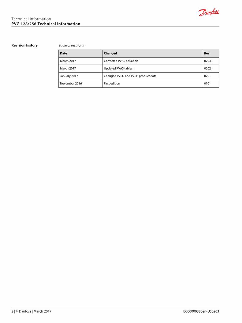
Revision history Table of revisions
Date Changed Rev
March 2017 Corrected PVAS equation 0203
March 2017 Updated PVAS tables 0202
January 2017 Changed PVEO and PVEH product data 0201
November 2016 First edition 0101
Technical InformationPVG 128/256 Technical Information
2 | © Danfoss | March 2017 BC00000380en-US0203
General InformationPVG 128/256 Proportional Valve Group...................................................................................................................................5General description......................................................................................................................................................................... 6Features of the PVG 128/256 valve............................................................................................................................................ 6
PVPV Inlet ModulesClosed Center PPRV for PVE Activation and/or Mechanical..............................................................................................8PPRV for PVH/PVHC Activation and/or Mechanical ..........................................................................................................10
PVB 128 Variant OverviewPVB 128 3-way Compensator.................................................................................................................................................... 13PVB 128 3-way Compensator with LS A/B.............................................................................................................................16PVB 128 3-way Compensator with LS A/B and PVLP.........................................................................................................19
PVB 256 Variant OverviewPVB 256 3-way Compensator.................................................................................................................................................... 25PVB 256 3-way Compensator with LS A/B.............................................................................................................................28PVB 256 3-way Compensator with LSA/B and PVLP..........................................................................................................31PVB 256 3-way Compensator with LS A/B, PVLP and Turbo...........................................................................................35
PVLP Shock and PVLA Suction Valves
PVBS PVE Electric Activation and/or MechanicalPVBS Variant Overview for PVB 128/256................................................................................................................................42Flow Control PVBS closed neutral position for PVB 128/256......................................................................................... 43Flow Control PVBS Throttled Open Neutral Position for PVB 128/256.......................................................................45Flow Control PVBS 3-way, 3-position for PVB 128/256.................................................................................................... 47Flow Control PVBS with Float for PVB 128/256 (P→A→F)..............................................................................................49
Hydraulic Activation and/or MechanicalPVBS Variant Overview for PVB 128/256................................................................................................................................50Flow Control PVBS closed neutral position for PVB 128/256......................................................................................... 51Flow Control PVBS Throttled open neutral position for PVB 128/256........................................................................53Flow Control PVBS 3-way, 3-position for PVB 128/256.................................................................................................... 55Flow Control PVBS with Float for PVB 128/256 (P→A→F)..............................................................................................57
PVM Manual Activation
PVH Hydraulic Actuation
PVHC Electro-Hydraulic Actuator type
PVMD Cover Manual Actuation Only
PVE Electrical ActuatorPVE Electrical Actuator................................................................................................................................................................. 64
PVE Variant OverviewPVE Variant Overview................................................................................................................................................................... 66PVEO................................................................................................................................................................................................... 67
PVEO Schematics and Dimensions.....................................................................................................................................67PVEO Technical Data............................................................................................................................................................... 68PVEO Reaction Times...............................................................................................................................................................69PVEO Variants for PVG.............................................................................................................................................................69
PVEH....................................................................................................................................................................................................70PVEH Schematics and Dimensions.....................................................................................................................................70PVEH Technical Data................................................................................................................................................................71PVEH Reaction Times...............................................................................................................................................................72PVEH Hysteresis and Ripple.................................................................................................................................................. 73PVEH Variants for PVG.............................................................................................................................................................73
Connector OverviewConnector Overview..................................................................................................................................................................... 74
Fault Monitoring and Fault ReactionGeneric Fault Reaction................................................................................................................................................................. 75
Technical InformationPVG 128/256 Technical Information
Contents
© Danfoss | March 2017 BC00000380en-US0203 | 3
Fault Reaction Overview..............................................................................................................................................................76
Functionality OverviewStandard and Fixed US 0-10 Vdc.............................................................................................................................................. 77
PWM Voltage Control..............................................................................................................................................................77Float A-Port (-FLA)..........................................................................................................................................................................79Power Save....................................................................................................................................................................................... 79
Special FeaturesDedicated Float Pin (UF)..............................................................................................................................................................80Disable Mode...................................................................................................................................................................................80
Performance OverviewReaction Times................................................................................................................................................................................81Hysteresis and Ripple................................................................................................................................................................... 81Oil Consumption............................................................................................................................................................................ 82
PVSI/PVGI End and Interface PlatesPVGI Interface Plate ......................................................................................................................................................................84PVSI with P and T port.................................................................................................................................................................. 85PVSI with or without LX connection........................................................................................................................................86
PVASPVAS for Combo............................................................................................................................................................................. 88PVAS P/N Overview....................................................................................................................................................................... 89
Valve Schematics
Technical InformationPVG 128/256 Technical Information
Contents
4 | © Danfoss | March 2017 BC00000380en-US0203
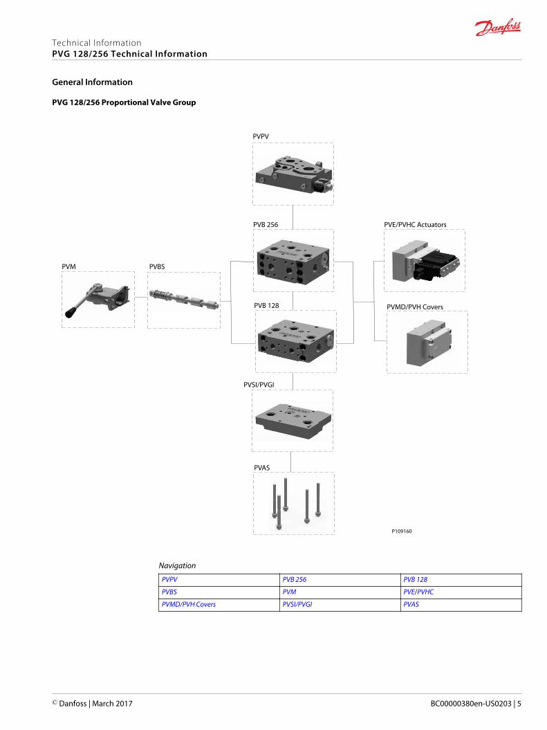
PVG 128/256 Proportional Valve Group
PVPV
PVE/PVHC ActuatorsPVB 256
PVM PVBS
PVB 128 PVMD/PVH Covers
PVSI/PVGI
PVAS
P109160
Navigation
PVPV PVB 256 PVB 128
PVBS PVM PVE/PVHC
PVMD/PVH Covers PVSI/PVGI PVAS
Technical InformationPVG 128/256 Technical Information
General Information
© Danfoss | March 2017 BC00000380en-US0203 | 5
General description
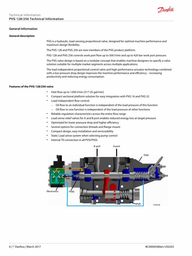
PVG is a hydraulic, load-sensing proportional valve, designed for optimal machine performance andmaximum design flexibility.
The PVG 128 and PVG 256 are new members of the PVG product platform.
PVG 128 and PVG 256 controls work port flow up to 500 l/min and up to 420 bar work port pressure.
The PVG valve design is based on a modular concept that enables machine designers to specify a valvesolution suitable for multiple market segments across multiple applications.
The load independent proportional control valve and high performance actuator technology combinedwith a low pressure drop design improves the machine performance and efficiency – increasingproductivity and reducing energy consumption.
Features of the PVG 128/256 valve
• Inlet flow up to 1200 l/min [317 US gal/min]• Compact sectional platform solution for easy integration with PVG 16 and PVG 32• Load-independent flow control:
‒ Oil flow to an individual function is independent of the load pressure of this function
‒ Oil flow to one function is independent of the load pressure of other functions• Reliable regulation characteristics across the entire flow range• Load sense relief valves for A and B port enables reduced energy loss at target pressure• Optimized for lower pressure drop and higher efficiency• Several options for connection threads and flange mount• Compact design, easy installation and serviceability• Static Load sense system when selecting pump control• Internal T0 connection in all PVSI/PVGI
Technical InformationPVG 128/256 Technical Information
General Information
6 | © Danfoss | March 2017 BC00000380en-US0203
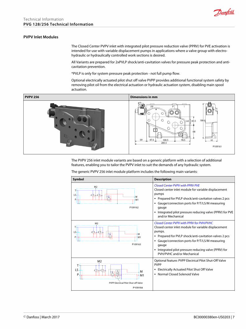
The Closed Center PVPV inlet with integrated pilot pressure reduction valve (PPRV) for PVE activation isintended for use with variable displacement pumps in applications where a valve group with electro-hydraulic or hydraulically controlled work sections is desired.
All Variants are prepared for 2xPVLP shock/anti-cavitation valves for pressure peak protection and anti-cavitation prevention.
*PVLP is only for system pressure peak protection - not full pump flow.
Optional electrically actuated pilot shut off valve PVPP provides additional functional system safety byremoving pilot oil from the electrical actuation or hydraulic actuation system, disabling main spoolactuation.
PVPV 256 Dimensions in mm
59 47.5285.5
100.5 78.5
68
43.5 180.6
P109161
62
The PVPV 256 inlet module variants are based on a generic platform with a selection of additionalfeatures, enabling you to tailor the PVPV inlet to suit the demands of any hydraulic system.
The generic PVPV 256 inlet module platform includes the following main variants:
Symbol Description
MM1
M2T
LS
P
P109162
Closed Center PVPV with PPRV PVEClosed center inlet module for variable displacementpumps• Prepared for PVLP shock/anti-cavitation valves 2 pcs• Gauge/connection ports for P/T/LS/M measuring
gauge• Integrated pilot pressure reducing valve (PPRV) for PVE
and/or Mechanical
MM1
M2T
LS
P
P109163
Closed Center PVPV with PPRV for PVH/PVHCClosed center inlet module for variable displacementpumps.• Prepared for PVLP shock/anti-cavitation valves 2 pcs• Gauge/connection ports for P/T/LS/M measuring
gauge• Integrated pilot pressure reducing valve (PPRV) for
PVH/PVHC and/or Mechanical
PVPP Electrical Pilot Shut-off Valve
TLS
P
M2
MM1
P109164
Optional feature: PVPP Electrical Pilot Shut-Off ValvePVPP• Electrically Actuated Pilot Shut Off Valve• Normal Closed Solenoid Valve
Technical InformationPVG 128/256 Technical Information
PVPV Inlet Modules
© Danfoss | March 2017 BC00000380en-US0203 | 7
Closed Center PPRV for PVE Activation and/or Mechanical
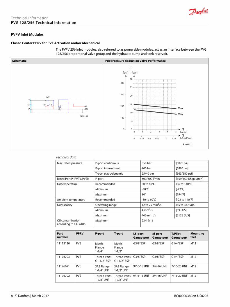
The PVPV 256 inlet modules, also referred to as pump side modules, act as an interface between the PVG128/256 proportional valve group and the hydraulic pump and tank reservoir.
Schematic Pilot Pressure Reduction Valve Performance
MM1
M2T
LS
P
P109162
[psi] [bar]P
Max
Min
Q
400
300
200
100
0
30
25
20
15
10
5
00 1 2 3 4 5
0 0.25 0.5 0.75 1.0 1.25Q
[l/min]
[US gal/min]
P109211
Technical data
Max. rated pressure P-port continuous 350 bar [5076 psi]
P-port intermittent 400 bar [5800 psi]
T-port static/dynamic 25/40 bar [363/580 psi]
Rated Port P (PVPV/PVSI) P-port 600/600 l/min [159/159 US gal/min]
Oil temperature Recommended 30 to 60°C [86 to 140°F]
Minimum -30°C [-22°F]
Maximum 90° [194°F]
Ambient temperature Recommended -30 to 60°C [-22 to 140°F]
Oil viscosity Operating range 12 to 75 mm2/s [65 to 347 SUS]
Minimum 4 mm2/s [39 SUS]
Maximum 460 mm2/s [2128 SUS]
Oil contaminationaccording to ISO 4406
Maximum 23/19/16
Partnumber
PPRV P-port T-port LS-portGauge-port
M-portGauge-port
T/PilotGauge-port
Mountingfeet
11173130 PVE MetricFlange1-1/4”
MetricFlange1-1/2”
G3/8"BSP G3/8"BSP G1/4"BSP M12
11176703 PVE Thread PortsG1-1/2" BSP
Thread PortsG1-1/2" BSP
G3/8"BSP G3/8"BSP G1/4"BSP M12
11176691 PVE SAE Flange1-1/4” UNF
SAE Flange1-1/2” UNF
9/16-18 UNF 3/4-16 UNF 7/16-20 UNF M12
11176702 PVE Thread Ports1-7/8” UNF
Thread Ports1-7/8” UNF
9/16-18 UNF 3/4-16 UNF 7/16-20 UNF M12
Technical InformationPVG 128/256 Technical Information
PVPV Inlet Modules
8 | © Danfoss | March 2017 BC00000380en-US0203
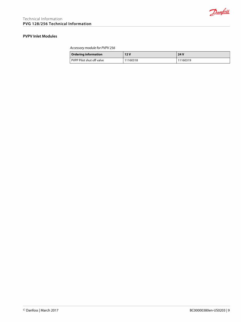
Accessory module for PVPV 256
Ordering information 12 V 24 V
PVPP Pilot shut off valve 11160318 11160319
Technical InformationPVG 128/256 Technical Information
PVPV Inlet Modules
© Danfoss | March 2017 BC00000380en-US0203 | 9
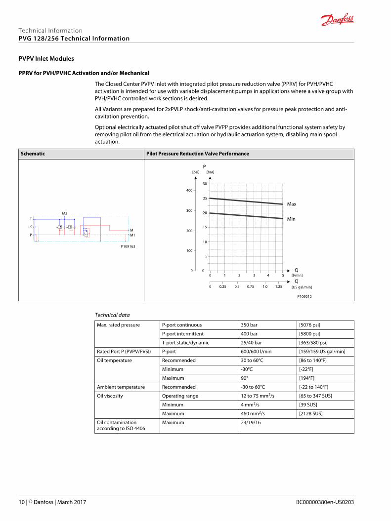
PPRV for PVH/PVHC Activation and/or Mechanical
The Closed Center PVPV inlet with integrated pilot pressure reduction valve (PPRV) for PVH/PVHCactivation is intended for use with variable displacement pumps in applications where a valve group withPVH/PVHC controlled work sections is desired.
All Variants are prepared for 2xPVLP shock/anti-cavitation valves for pressure peak protection and anti-cavitation prevention.
Optional electrically actuated pilot shut off valve PVPP provides additional functional system safety byremoving pilot oil from the electrical actuation or hydraulic actuation system, disabling main spoolactuation.
Schematic Pilot Pressure Reduction Valve Performance
MM1
M2T
LS
P
P109163
1 2 3 4 5
5
00
P
Max
Min
Q
Q
[psi] [bar]
400
300
200
100
0
30
25
20
15
10
0 0.25 0.5 0.75 1.0 1.25
[l/min]
[US gal/min]
P109212
Technical data
Max. rated pressure P-port continuous 350 bar [5076 psi]
P-port intermittent 400 bar [5800 psi]
T-port static/dynamic 25/40 bar [363/580 psi]
Rated Port P (PVPV/PVSI) P-port 600/600 l/min [159/159 US gal/min]
Oil temperature Recommended 30 to 60°C [86 to 140°F]
Minimum -30°C [-22°F]
Maximum 90° [194°F]
Ambient temperature Recommended -30 to 60°C [-22 to 140°F]
Oil viscosity Operating range 12 to 75 mm2/s [65 to 347 SUS]
Minimum 4 mm2/s [39 SUS]
Maximum 460 mm2/s [2128 SUS]
Oil contaminationaccording to ISO 4406
Maximum 23/19/16
Technical InformationPVG 128/256 Technical Information
PVPV Inlet Modules
10 | © Danfoss | March 2017 BC00000380en-US0203
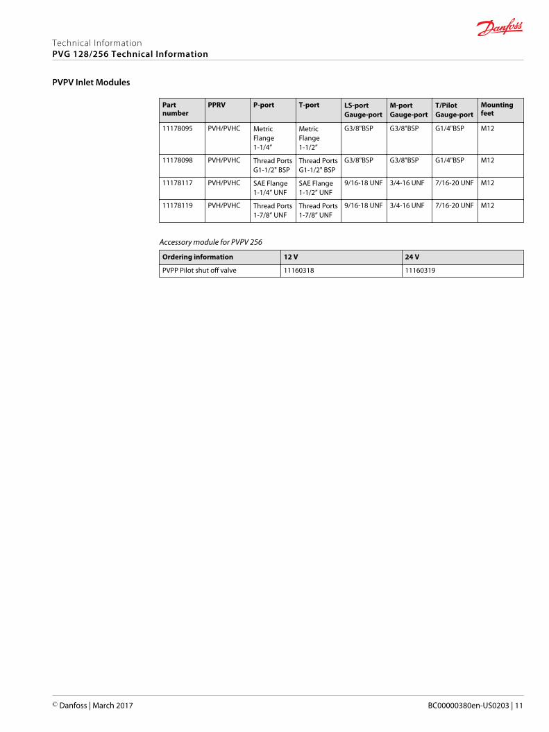
Partnumber
PPRV P-port T-port LS-portGauge-port
M-portGauge-port
T/PilotGauge-port
Mountingfeet
11178095 PVH/PVHC MetricFlange1-1/4”
MetricFlange1-1/2”
G3/8"BSP G3/8"BSP G1/4"BSP M12
11178098 PVH/PVHC Thread PortsG1-1/2" BSP
Thread PortsG1-1/2" BSP
G3/8"BSP G3/8"BSP G1/4"BSP M12
11178117 PVH/PVHC SAE Flange1-1/4” UNF
SAE Flange1-1/2” UNF
9/16-18 UNF 3/4-16 UNF 7/16-20 UNF M12
11178119 PVH/PVHC Thread Ports1-7/8” UNF
Thread Ports1-7/8” UNF
9/16-18 UNF 3/4-16 UNF 7/16-20 UNF M12
Accessory module for PVPV 256
Ordering information 12 V 24 V
PVPP Pilot shut off valve 11160318 11160319
Technical InformationPVG 128/256 Technical Information
PVPV Inlet Modules
© Danfoss | March 2017 BC00000380en-US0203 | 11
PVB 128 Dimensions (mm)
182.
2
20523.5
66
107
178.
8
33
P109171
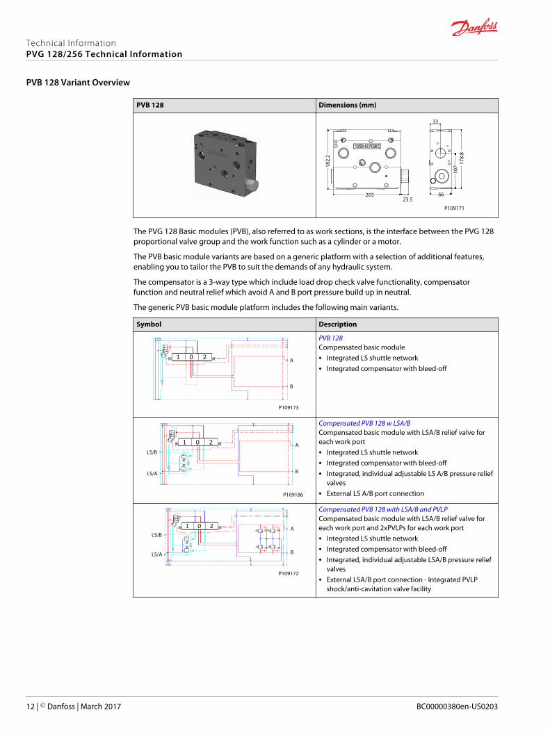
The PVG 128 Basic modules (PVB), also referred to as work sections, is the interface between the PVG 128proportional valve group and the work function such as a cylinder or a motor.
The PVB basic module variants are based on a generic platform with a selection of additional features,enabling you to tailor the PVB to suit the demands of any hydraulic system.
The compensator is a 3-way type which include load drop check valve functionality, compensatorfunction and neutral relief which avoid A and B port pressure build up in neutral.
The generic PVB basic module platform includes the following main variants.
Symbol Description
A
B
P109173
PVB 128Compensated basic module• Integrated LS shuttle network• Integrated compensator with bleed-off
A
B
LS/B
LS/A
P109186
Compensated PVB 128 w LSA/BCompensated basic module with LSA/B relief valve foreach work port• Integrated LS shuttle network• Integrated compensator with bleed-off• Integrated, individual adjustable LS A/B pressure relief
valves• External LS A/B port connection
LS/B
LS/A B
A
P109172
Compensated PVB 128 with LSA/B and PVLPCompensated basic module with LSA/B relief valve foreach work port and 2xPVLPs for each work port• Integrated LS shuttle network• Integrated compensator with bleed-off• Integrated, individual adjustable LSA/B pressure relief
valves• External LSA/B port connection - Integrated PVLP
shock/anti-cavitation valve facility
Technical InformationPVG 128/256 Technical Information
PVB 128 Variant Overview
12 | © Danfoss | March 2017 BC00000380en-US0203
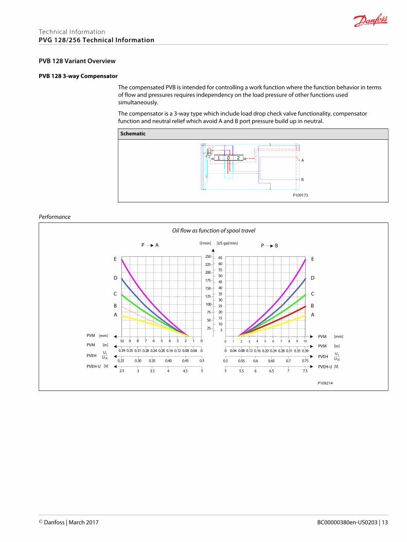
PVB 128 3-way Compensator
The compensated PVB is intended for controlling a work function where the function behavior in termsof flow and pressures requires independency on the load pressure of other functions usedsimultaneously.
The compensator is a 3-way type which include load drop check valve functionality, compensatorfunction and neutral relief which avoid A and B port pressure build up in neutral.
Schematic
A
B
P109173
Performance
Oil flow as function of spool travel
AP
25
50
75
100
125
150
175
200
225
250
PVM01234567
PVM00.040.080.120.160.200.240.28
PVEH0.50.450.400.350.30
8
0.31
0.25
910
0.350.39
5101520253035404550556065
BP
PVM1098765
PVM0.390.350.310.280.240.20
PVEHUs
UDC0.70.650.60.55
4
0.16
0.5
3210
0.120.080.040
0.75PVEH-U
52.5PVEH-U
5 7.5[V]
A
B
C
D
E
A
B
C
D
E
3 3.5 4 4.5 75.5 6 6.5
[mm]
[in]
Us
UDC
[V]
[mm]
[in]
[l/min] [US gal/min]
P109214
Technical InformationPVG 128/256 Technical Information
PVB 128 Variant Overview
© Danfoss | March 2017 BC00000380en-US0203 | 13
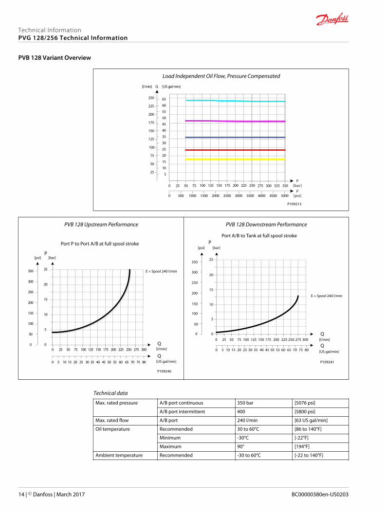
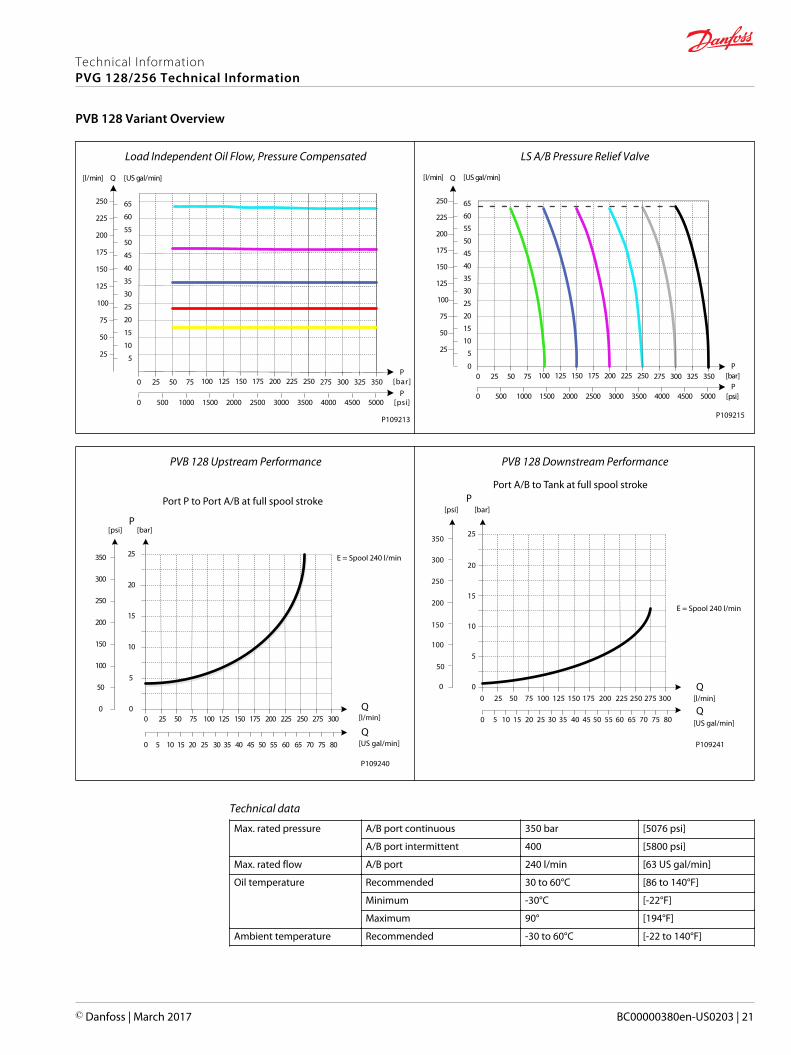
Load Independent Oil Flow, Pressure Compensated
25
50
75
100
125
150
175
200
225
250
[l/min] [US gal/min]
5
10
15
20
25
30
35
40
45
50
55
60
65
2502252001751501251007550250
Q
350325300275P
P25002000150010005000 35003000 4000 50004500
[bar]
[psi]
P109213
PVB 128 Upstream Performance
25 50 75 100 125 150 175 200 225 250 275 300
5 10 15 20 25 30 35 40 45 50 55 60 65 70 75 80
25
20
15
10
5
0
250
200
150
100
50
0
350
300
0
0
Port P to Port A/B at full spool stroke
E = Spool 240 l/min
P
Q
Q
[psi] [bar]
[l/min]
[US gal/min]
P109240
PVB 128 Downstream Performance
5
00
PPort A/B to Tank at full spool stroke
Q
Q
[psi] [bar]
350
300
200
150
100
50
250
0 25 50 75 100 125 150 175 200 225 250 275 300
25
20
15
10
0 5 10 15 20 25 30 35 40 45 50 55 60 65 70 75 80
E = Spool 240 l/min
[l/min]
[US gal/min]
P109241
Technical data
Max. rated pressure A/B port continuous 350 bar [5076 psi]
A/B port intermittent 400 [5800 psi]
Max. rated flow A/B port 240 l/min [63 US gal/min]
Oil temperature Recommended 30 to 60°C [86 to 140°F]
Minimum -30°C [-22°F]
Maximum 90° [194°F]
Ambient temperature Recommended -30 to 60°C [-22 to 140°F]
Technical InformationPVG 128/256 Technical Information
PVB 128 Variant Overview
14 | © Danfoss | March 2017 BC00000380en-US0203
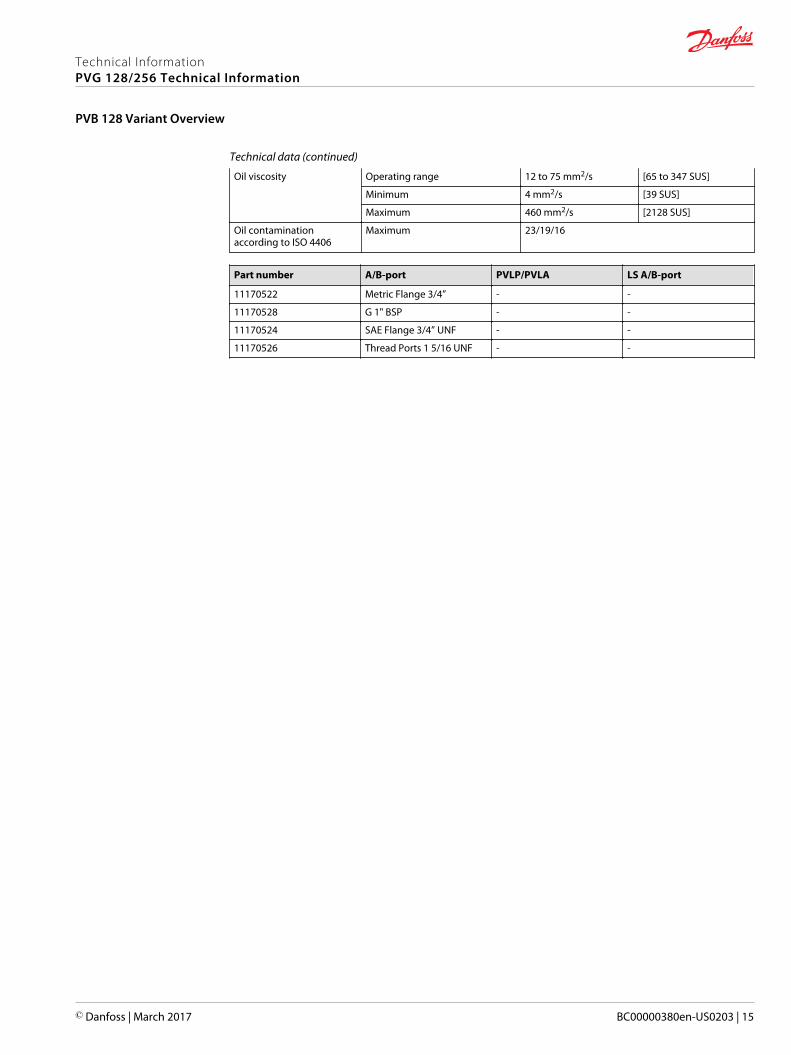
Technical data (continued)
Oil viscosity Operating range 12 to 75 mm2/s [65 to 347 SUS]
Minimum 4 mm2/s [39 SUS]
Maximum 460 mm2/s [2128 SUS]
Oil contaminationaccording to ISO 4406
Maximum 23/19/16
Part number A/B-port PVLP/PVLA LS A/B-port
11170522 Metric Flange 3/4” - -
11170528 G 1" BSP - -
11170524 SAE Flange 3/4” UNF - -
11170526 Thread Ports 1 5/16 UNF - -
Technical InformationPVG 128/256 Technical Information
PVB 128 Variant Overview
© Danfoss | March 2017 BC00000380en-US0203 | 15
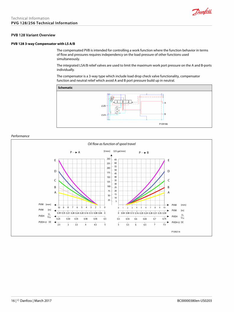
PVB 128 3-way Compensator with LS A/B
The compensated PVB is intended for controlling a work function where the function behavior in termsof flow and pressures requires independency on the load pressure of other functions usedsimultaneously.
The integrated LSA/B relief valves are used to limit the maximum work port pressure on the A and B-portsindividually.
The compensator is a 3-way type which include load drop check valve functionality, compensatorfunction and neutral relief which avoid A and B port pressure build up in neutral.
Schematic
A
B
LS/B
LS/A
P109186
Performance
Oil flow as function of spool travel
AP
25
50
75
100
125
150
175
200
225
250
PVM01234567
PVM00.040.080.120.160.200.240.28
PVEH0.50.450.400.350.30
8
0.31
0.25
910
0.350.39
5101520253035404550556065
BP
PVM1098765
PVM0.390.350.310.280.240.20
PVEHUs
UDC0.70.650.60.55
4
0.16
0.5
3210
0.120.080.040
0.75PVEH-U
52.5PVEH-U
5 7.5[V]
A
B
C
D
E
A
B
C
D
E
3 3.5 4 4.5 75.5 6 6.5
[mm]
[in]
Us
UDC
[V]
[mm]
[in]
[l/min] [US gal/min]
P109214
Technical InformationPVG 128/256 Technical Information
PVB 128 Variant Overview
16 | © Danfoss | March 2017 BC00000380en-US0203

Load Independent Oil Flow, Pressure Compensated
25
50
75
100
125
150
175
200
225
250
[l/min] [US gal/min]
5
10
15
20
25
30
35
40
45
50
55
60
65
2502252001751501251007550250
Q
350325300275P
P25002000150010005000 35003000 4000 50004500
[bar]
[psi]
P109213
LS A/B Pressure Relief Valve
25
50
75
100
125
150
175
200
225
250
[l/min] [US gal/min]
5
10
15
20
25
30
35
40
45
50
55
60
65
2502252001751501251007550250
Q
350325300275P
P25002000150010005000 35003000 4000 50004500
0[bar]
[psi]
P109215
PVB 128 Upstream Performance
25 50 75 100 125 150 175 200 225 250 275 300
5 10 15 20 25 30 35 40 45 50 55 60 65 70 75 80
25
20
15
10
5
0
250
200
150
100
50
0
350
300
0
0
Port P to Port A/B at full spool stroke
E = Spool 240 l/min
P
Q
Q
[psi] [bar]
[l/min]
[US gal/min]
P109240
PVB 128 Downstream Performance
5
00
PPort A/B to Tank at full spool stroke
Q
Q
[psi] [bar]
350
300
200
150
100
50
250
0 25 50 75 100 125 150 175 200 225 250 275 300
25
20
15
10
0 5 10 15 20 25 30 35 40 45 50 55 60 65 70 75 80
E = Spool 240 l/min
[l/min]
[US gal/min]
P109241
Technical data
Max. rated pressure A/B port continuous 350 bar [5076 psi]
A/B port intermittent 400 [5800 psi]
Max. rated flow A/B port 240 l/min [63 US gal/min]
Oil temperature Recommended 30 to 60°C [86 to 140°F]
Minimum -30°C [-22°F]
Maximum 90° [194°F]
Ambient temperature Recommended -30 to 60°C [-22 to 140°F]
Technical InformationPVG 128/256 Technical Information
PVB 128 Variant Overview
© Danfoss | March 2017 BC00000380en-US0203 | 17
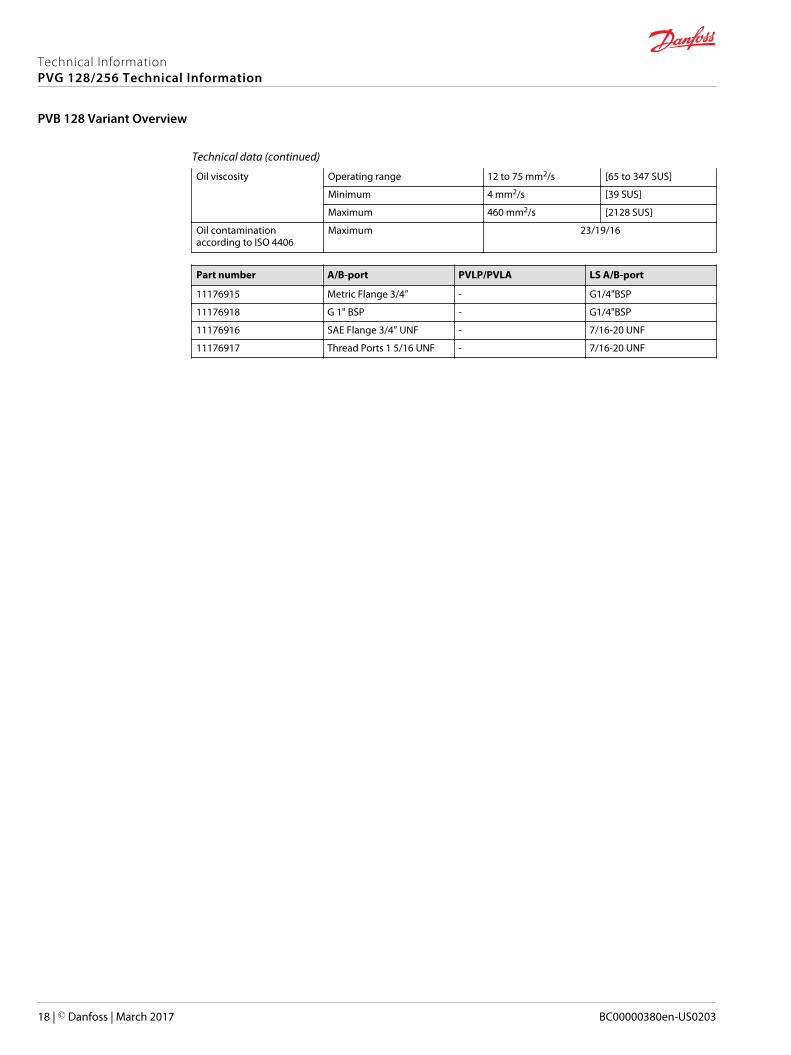
Technical data (continued)
Oil viscosity Operating range 12 to 75 mm2/s [65 to 347 SUS]
Minimum 4 mm2/s [39 SUS]
Maximum 460 mm2/s [2128 SUS]
Oil contaminationaccording to ISO 4406
Maximum 23/19/16
Part number A/B-port PVLP/PVLA LS A/B-port
11176915 Metric Flange 3/4” - G1/4"BSP
11176918 G 1" BSP - G1/4"BSP
11176916 SAE Flange 3/4” UNF - 7/16-20 UNF
11176917 Thread Ports 1 5/16 UNF - 7/16-20 UNF
Technical InformationPVG 128/256 Technical Information
PVB 128 Variant Overview
18 | © Danfoss | March 2017 BC00000380en-US0203
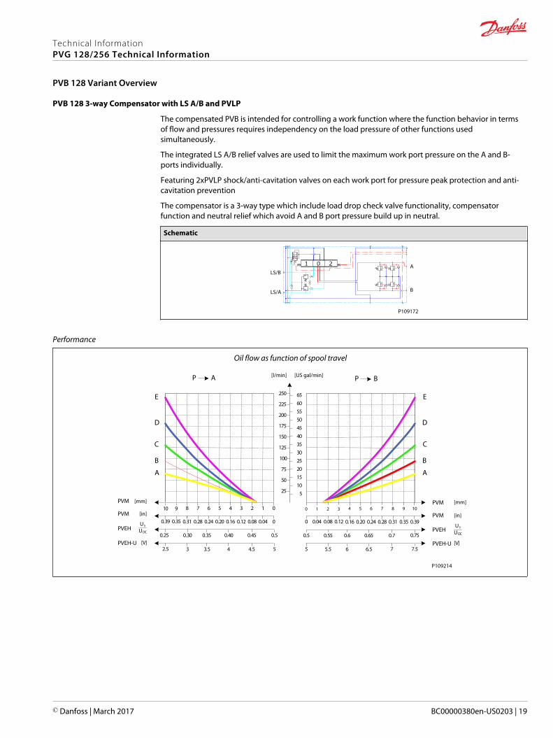
PVB 128 3-way Compensator with LS A/B and PVLP
The compensated PVB is intended for controlling a work function where the function behavior in termsof flow and pressures requires independency on the load pressure of other functions usedsimultaneously.
The integrated LS A/B relief valves are used to limit the maximum work port pressure on the A and B-ports individually.
Featuring 2xPVLP shock/anti-cavitation valves on each work port for pressure peak protection and anti-cavitation prevention
The compensator is a 3-way type which include load drop check valve functionality, compensatorfunction and neutral relief which avoid A and B port pressure build up in neutral.
Schematic
LS/B
LS/A B
A
P109172
Performance
Oil flow as function of spool travel
AP
25
50
75
100
125
150
175
200
225
250
PVM01234567
PVM00.040.080.120.160.200.240.28
PVEH0.50.450.400.350.30
8
0.31
0.25
910
0.350.39
5101520253035404550556065
BP
PVM1098765
PVM0.390.350.310.280.240.20
PVEHUs
UDC0.70.650.60.55
4
0.16
0.5
3210
0.120.080.040
0.75PVEH-U
52.5PVEH-U
5 7.5[V]
A
B
C
D
E
A
B
C
D
E
3 3.5 4 4.5 75.5 6 6.5
[mm]
[in]
Us
UDC
[V]
[mm]
[in]
[l/min] [US gal/min]
P109214
Technical InformationPVG 128/256 Technical Information
PVB 128 Variant Overview
© Danfoss | March 2017 BC00000380en-US0203 | 19
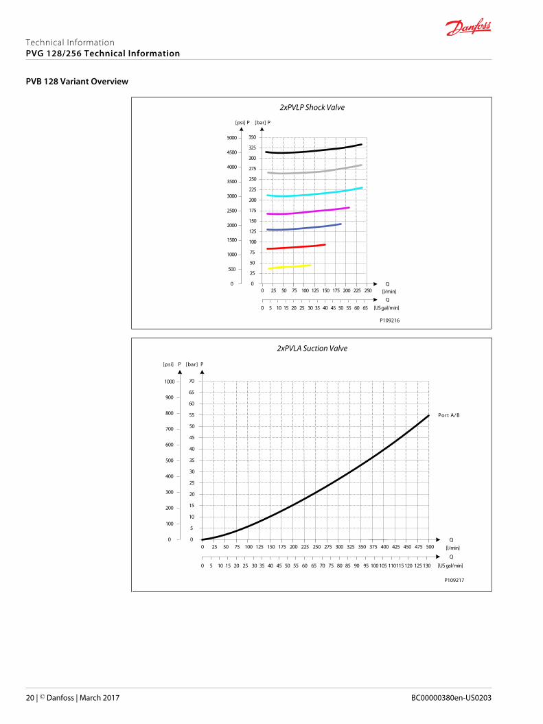
2xPVLP Shock Valve
25 50 75 100 125 150 175 200 225 250 [l/min]
[USgal/min]5 10 15 20 25 30 35 40 45 50 55 60 65
250
225
200
175
150
125
100
75
50
25
0
Q
350
325
300
275
PP
2500
2000
1500
1000
500
0
3500
3000
4000
5000
4500
0
[psi] [bar]
0
Q
P109216
2xPVLA Suction Valve
25 50 75 100 125 150 175 200 225 250 275 300 325 [l/min]
[US gal/min]
350 375 400
5 10 15 20 25 30 35 40 45 50 55 60 65 70 75 80 85 90 95 100 105
50
45
40
35
30
25
20
15
10
5
0425 450 475 500
110115120 125 130
Q
70
65
60
55
PP
500
400
300
200
100
0
700
600
800
1000
900
0
[psi] [bar]
0
Q
Port A/B
P109217
Technical InformationPVG 128/256 Technical Information
PVB 128 Variant Overview
20 | © Danfoss | March 2017 BC00000380en-US0203
Load Independent Oil Flow, Pressure Compensated
25
50
75
100
125
150
175
200
225
250
[l/min] [US gal/min]
5
10
15
20
25
30
35
40
45
50
55
60
65
2502252001751501251007550250
Q
350325300275P
P25002000150010005000 35003000 4000 50004500
[bar]
[psi]
P109213
LS A/B Pressure Relief Valve
25
50
75
100
125
150
175
200
225
250
[l/min] [US gal/min]
5
10
15
20
25
30
35
40
45
50
55
60
65
2502252001751501251007550250
Q
350325300275P
P25002000150010005000 35003000 4000 50004500
0[bar]
[psi]
P109215
PVB 128 Upstream Performance
25 50 75 100 125 150 175 200 225 250 275 300
5 10 15 20 25 30 35 40 45 50 55 60 65 70 75 80
25
20
15
10
5
0
250
200
150
100
50
0
350
300
0
0
Port P to Port A/B at full spool stroke
E = Spool 240 l/min
P
Q
Q
[psi] [bar]
[l/min]
[US gal/min]
P109240
PVB 128 Downstream Performance
5
00
PPort A/B to Tank at full spool stroke
Q
Q
[psi] [bar]
350
300
200
150
100
50
250
0 25 50 75 100 125 150 175 200 225 250 275 300
25
20
15
10
0 5 10 15 20 25 30 35 40 45 50 55 60 65 70 75 80
E = Spool 240 l/min
[l/min]
[US gal/min]
P109241
Technical data
Max. rated pressure A/B port continuous 350 bar [5076 psi]
A/B port intermittent 400 [5800 psi]
Max. rated flow A/B port 240 l/min [63 US gal/min]
Oil temperature Recommended 30 to 60°C [86 to 140°F]
Minimum -30°C [-22°F]
Maximum 90° [194°F]
Ambient temperature Recommended -30 to 60°C [-22 to 140°F]
Technical InformationPVG 128/256 Technical Information
PVB 128 Variant Overview
© Danfoss | March 2017 BC00000380en-US0203 | 21
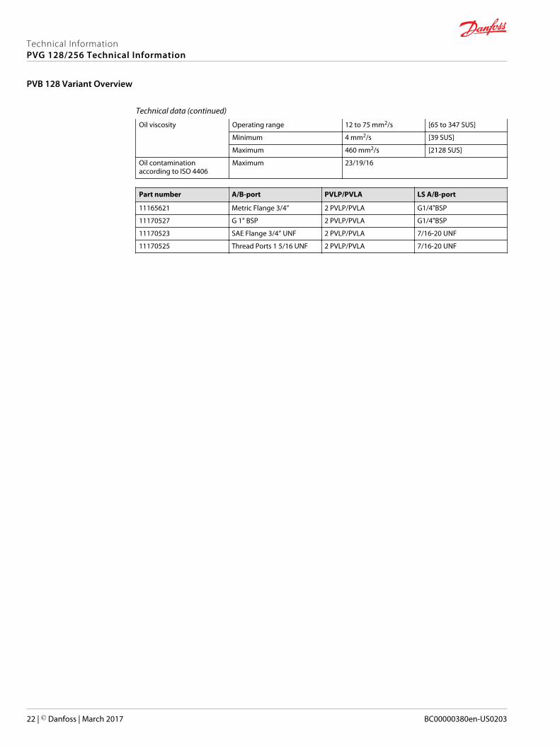
Technical data (continued)
Oil viscosity Operating range 12 to 75 mm2/s [65 to 347 SUS]
Minimum 4 mm2/s [39 SUS]
Maximum 460 mm2/s [2128 SUS]
Oil contaminationaccording to ISO 4406
Maximum 23/19/16
Part number A/B-port PVLP/PVLA LS A/B-port
11165621 Metric Flange 3/4” 2 PVLP/PVLA G1/4"BSP
11170527 G 1" BSP 2 PVLP/PVLA G1/4"BSP
11170523 SAE Flange 3/4” UNF 2 PVLP/PVLA 7/16-20 UNF
11170525 Thread Ports 1 5/16 UNF 2 PVLP/PVLA 7/16-20 UNF
Technical InformationPVG 128/256 Technical Information
PVB 128 Variant Overview
22 | © Danfoss | March 2017 BC00000380en-US0203
PVB 256 Dimensions (mm)
182.
2
20523.5
86
107
178.
5
43
P109242
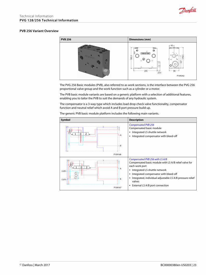
The PVG 256 Basic modules (PVB), also referred to as work sections, is the interface between the PVG 256proportional valve group and the work function such as a cylinder or a motor.
The PVB basic module variants are based on a generic platform with a selection of additional features,enabling you to tailor the PVB to suit the demands of any hydraulic system.
The compensator is a 3-way type which includes load drop check valve functionality, compensatorfunction and neutral relief which avoid A and B port pressure build up.
The generic PVB basic module platform includes the following main variants.
Symbol Description
A
B
P109168
Compensated PVB 256Compensated basic module• Integrated LS shuttle network• Integrated compensator with bleed-off
LS/B
LS/A
A
B
P109167
Compensated PVB 256 with LS A/BCompensated basic module with LS A/B relief valve foreach work port• Integrated LS shuttle network• Integrated compensator with bleed-off• Integrated, individual adjustable LS A/B pressure relief
valves• External LS A/B port connection
Technical InformationPVG 128/256 Technical Information
PVB 256 Variant Overview
© Danfoss | March 2017 BC00000380en-US0203 | 23
Symbol Description
LS/B
LS/A
A
B
P109166
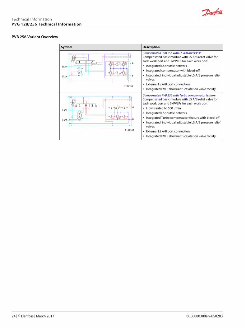
Compensated PVB 256 with LS A/B and PVLPCompensated basic module with LS A/B relief valve foreach work port and 3xPVLPs for each work port• Integrated LS shuttle network• Integrated compensator with bleed-off• Integrated, individual adjustable LS A/B pressure relief
valves• External LS A/B port connection• Integrated PVLP shock/anti-cavitation valve facility
LS/B
LS/A B
A
P109165
Compensated PVB 256 with Turbo compensator featureCompensated basic module with LS A/B relief valve foreach work port and 3xPVLPs for each work port• Flow is rated to 500 l/min• Integrated LS shuttle network• Integrated Turbo compensator feature with bleed-off• Integrated, individual adjustable LS A/B pressure relief
valves• External LS A/B port connection• Integrated PVLP shock/anti-cavitation valve facility
Technical InformationPVG 128/256 Technical Information
PVB 256 Variant Overview
24 | © Danfoss | March 2017 BC00000380en-US0203
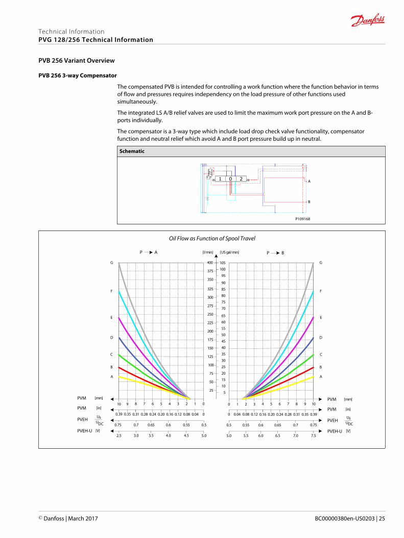
PVB 256 3-way Compensator
The compensated PVB is intended for controlling a work function where the function behavior in termsof flow and pressures requires independency on the load pressure of other functions usedsimultaneously.
The integrated LS A/B relief valves are used to limit the maximum work port pressure on the A and B-ports individually.
The compensator is a 3-way type which include load drop check valve functionality, compensatorfunction and neutral relief which avoid A and B port pressure build up in neutral.
Schematic
A
B
P109168
Oil Flow as Function of Spool Travel
AP
25
50
75
100
125
150
175
200
225
250
275
300
325
[l/min] [US gal/min]
[mm]PVM01234567
[in]PVM00.040.080.120.160.200.240.28
PVEHUs
UDC 0.50.550.60.650.7
8
0.31
0.75
910
350
375
400
0.350.39
5
10
15
20
25
30
35
40
45
50
55
60
65
70
75
80
85
90
95
100
105
BP
[mm]PVM1098765
[in]PVM0.390.350.310.280.240.20
PVEHUs
UDC0.70.650.60.55
4
0.16
0.5
3210
0.120.080.040
0.75
PVEH-U5.02.5
PVEH-U5.0 7.5
[V][V]
A
B
C
D
E
F
G
A
B
C
D
E
F
G
4.54.03.53.0 7.06.56.05.5
Technical InformationPVG 128/256 Technical Information
PVB 256 Variant Overview
© Danfoss | March 2017 BC00000380en-US0203 | 25
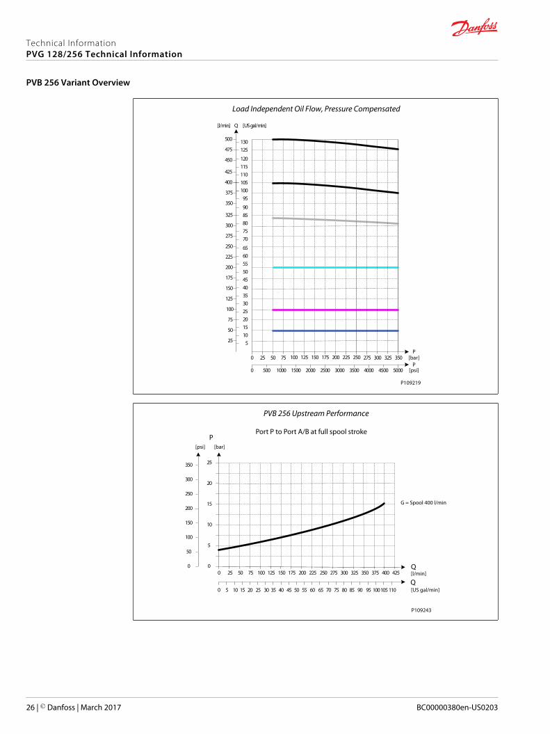
Load Independent Oil Flow, Pressure Compensated
25
50
75
100
125
150
175
200
225
250
275
300
325
[l/min] [US gal/min]
350
375
400
5101520253035404550556065
7075808590
95100105
2502252001751501251007550250
425
450
475
500
110115120
125130
Q
350325300275P
P25002000150010005000 35003000 4000 50004500
[bar]
[psi]
P109219
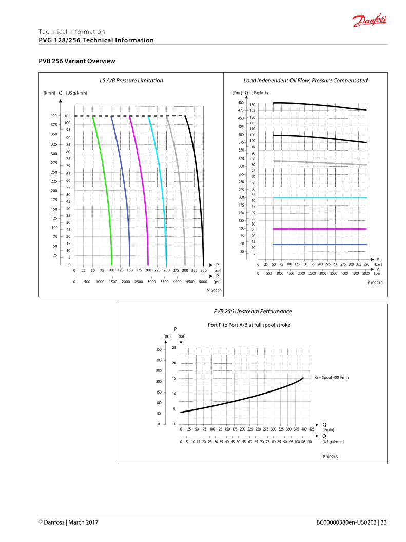
PVB 256 Upstream Performance
25 50 75 100 125 150 175 200 225 250 275 300 325 350 375 400
5 10 15 20 25 30 35 40 45 50 55 60 65 70 75 80 85 90 95 100105
25
20
15
10
5
0425
110
250
200
150
100
50
0
350
300
0
0
P[psi] [bar]
Q
Q[l/min]
[US gal/min]
Port P to Port A/B at full spool stroke
G = Spool 400 l/min
P109243
Technical InformationPVG 128/256 Technical Information
PVB 256 Variant Overview
26 | © Danfoss | March 2017 BC00000380en-US0203
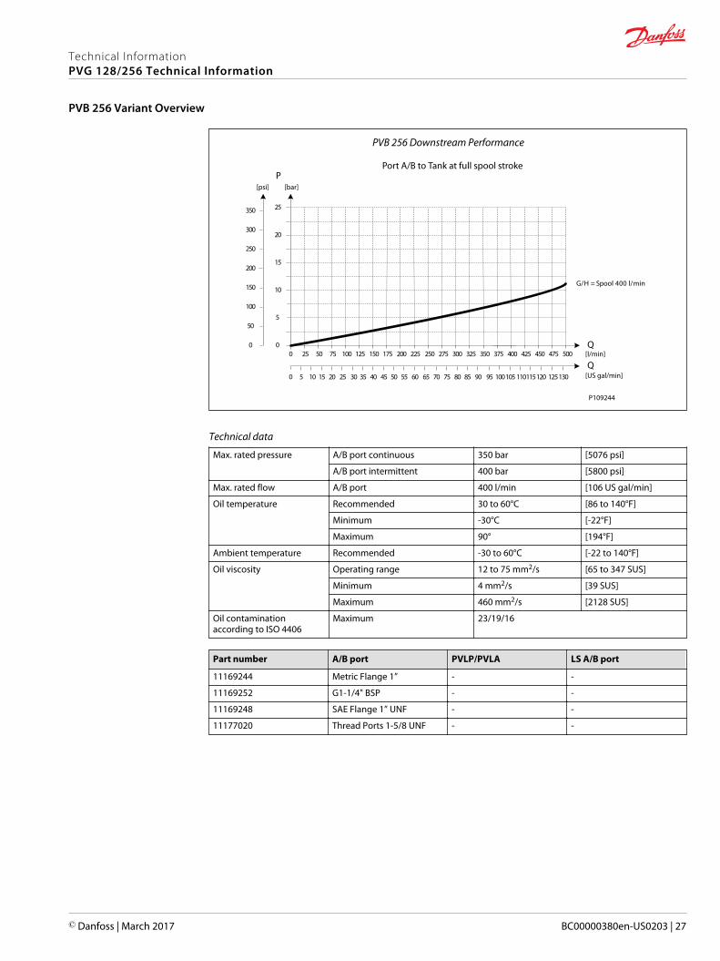
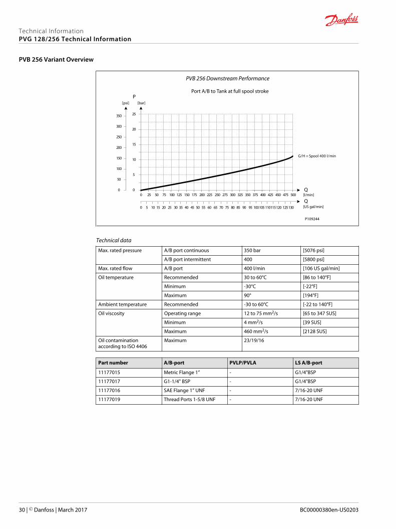
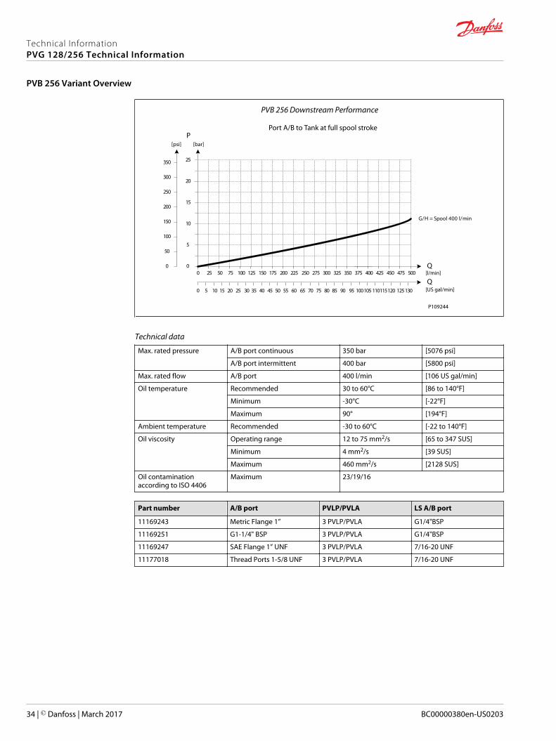
PVB 256 Downstream Performance
25 50 75 100 125 150 175 200 225 250 275 300 325 350 375 400
5 10 15 20 25 30 35 40 45 50 55 60 65 70 75 80 85 90 95 100105
25
20
15
10
5
0425 450 475 500
110115120 125130Q
P
250
200
150
100
50
0
350
300
0
0
Q
G/H = Spool 400 l/min
[psi] [bar]
[l/min]
[US gal/min]
Port A/B to Tank at full spool stroke
P109244
Technical data
Max. rated pressure A/B port continuous 350 bar [5076 psi]
A/B port intermittent 400 bar [5800 psi]
Max. rated flow A/B port 400 l/min [106 US gal/min]
Oil temperature Recommended 30 to 60°C [86 to 140°F]
Minimum -30°C [-22°F]
Maximum 90° [194°F]
Ambient temperature Recommended -30 to 60°C [-22 to 140°F]
Oil viscosity Operating range 12 to 75 mm2/s [65 to 347 SUS]
Minimum 4 mm2/s [39 SUS]
Maximum 460 mm2/s [2128 SUS]
Oil contaminationaccording to ISO 4406
Maximum 23/19/16
Part number A/B port PVLP/PVLA LS A/B port
11169244 Metric Flange 1” - -
11169252 G1-1/4" BSP - -
11169248 SAE Flange 1” UNF - -
11177020 Thread Ports 1-5/8 UNF - -
Technical InformationPVG 128/256 Technical Information
PVB 256 Variant Overview
© Danfoss | March 2017 BC00000380en-US0203 | 27
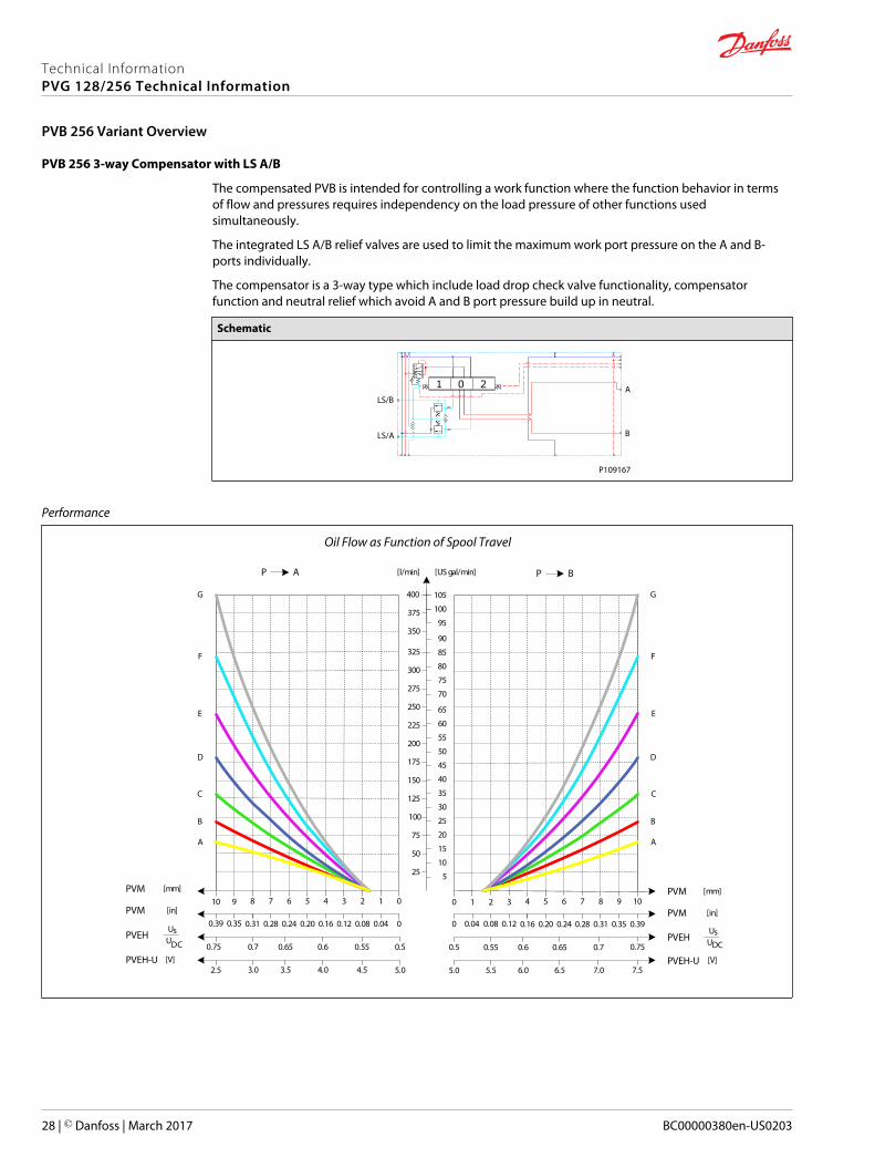
PVB 256 3-way Compensator with LS A/B
The compensated PVB is intended for controlling a work function where the function behavior in termsof flow and pressures requires independency on the load pressure of other functions usedsimultaneously.
The integrated LS A/B relief valves are used to limit the maximum work port pressure on the A and B-ports individually.
The compensator is a 3-way type which include load drop check valve functionality, compensatorfunction and neutral relief which avoid A and B port pressure build up in neutral.
Schematic
LS/B
LS/A
A
B
P109167
Performance
Oil Flow as Function of Spool Travel
AP
25
50
75
100
125
150
175
200
225
250
275
300
325
[l/min] [US gal/min]
[mm]PVM01234567
[in]PVM00.040.080.120.160.200.240.28
PVEHUs
UDC 0.50.550.60.650.7
8
0.31
0.75
910
350
375
400
0.350.39
5
10
15
20
25
30
35
40
45
50
55
60
65
70
75
80
85
90
95
100
105
BP
[mm]PVM1098765
[in]PVM0.390.350.310.280.240.20
PVEHUs
UDC0.70.650.60.55
4
0.16
0.5
3210
0.120.080.040
0.75
PVEH-U5.02.5
PVEH-U5.0 7.5
[V][V]
A
B
C
D
E
F
G
A
B
C
D
E
F
G
4.54.03.53.0 7.06.56.05.5
Technical InformationPVG 128/256 Technical Information
PVB 256 Variant Overview
28 | © Danfoss | March 2017 BC00000380en-US0203
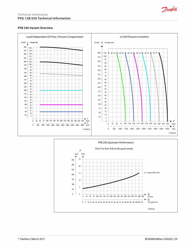
Load Independent Oil Flow, Pressure Compensated
25
50
75
100
125
150
175
200
225
250
275
300
325
[l/min] [US gal/min]
350
375
400
5101520253035404550556065
7075808590
95100105
2502252001751501251007550250
425
450
475
500
110115120
125130
Q
350325300275P
P25002000150010005000 35003000 4000 50004500
[bar]
[psi]
P109219
LS A/B Pressure Limitation
25
50
75
100
125
150
175
200
225
250
275
300
325
[l/min] [US gal/min]
350
375
400
5
10
15
20
25
30
35
40
45
50
55
60
65
70
75
80
85
90
95
100
105
2502252001751501251007550250
Q
350325300275P
P25002000150010005000 35003000 4000 50004500
0[bar]
[psi]
P109220
PVB 256 Upstream Performance
25 50 75 100 125 150 175 200 225 250 275 300 325 350 375 400
5 10 15 20 25 30 35 40 45 50 55 60 65 70 75 80 85 90 95 100105
25
20
15
10
5
0425
110
250
200
150
100
50
0
350
300
0
0
P[psi] [bar]
Q
Q[l/min]
[US gal/min]
Port P to Port A/B at full spool stroke
G = Spool 400 l/min
P109243
Technical InformationPVG 128/256 Technical Information
PVB 256 Variant Overview
© Danfoss | March 2017 BC00000380en-US0203 | 29
PVB 256 Downstream Performance
25 50 75 100 125 150 175 200 225 250 275 300 325 350 375 400
5 10 15 20 25 30 35 40 45 50 55 60 65 70 75 80 85 90 95 100105
25
20
15
10
5
0425 450 475 500
110115120 125130Q
P
250
200
150
100
50
0
350
300
0
0
Q
G/H = Spool 400 l/min
[psi] [bar]
[l/min]
[US gal/min]
Port A/B to Tank at full spool stroke
P109244
Technical data
Max. rated pressure A/B port continuous 350 bar [5076 psi]
A/B port intermittent 400 [5800 psi]
Max. rated flow A/B port 400 l/min [106 US gal/min]
Oil temperature Recommended 30 to 60°C [86 to 140°F]
Minimum -30°C [-22°F]
Maximum 90° [194°F]
Ambient temperature Recommended -30 to 60°C [-22 to 140°F]
Oil viscosity Operating range 12 to 75 mm2/s [65 to 347 SUS]
Minimum 4 mm2/s [39 SUS]
Maximum 460 mm2/s [2128 SUS]
Oil contaminationaccording to ISO 4406
Maximum 23/19/16
Part number A/B-port PVLP/PVLA LS A/B-port
11177015 Metric Flange 1” - G1/4"BSP
11177017 G1-1/4" BSP - G1/4"BSP
11177016 SAE Flange 1” UNF - 7/16-20 UNF
11177019 Thread Ports 1-5/8 UNF - 7/16-20 UNF
Technical InformationPVG 128/256 Technical Information
PVB 256 Variant Overview
30 | © Danfoss | March 2017 BC00000380en-US0203
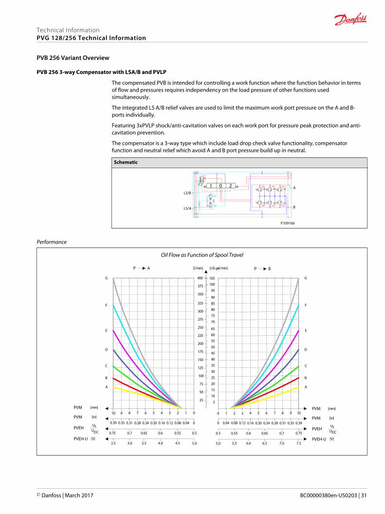
PVB 256 3-way Compensator with LSA/B and PVLP
The compensated PVB is intended for controlling a work function where the function behavior in termsof flow and pressures requires independency on the load pressure of other functions usedsimultaneously.
The integrated LS A/B relief valves are used to limit the maximum work port pressure on the A and B-ports individually.
Featuring 3xPVLP shock/anti-cavitation valves on each work port for pressure peak protection and anti-cavitation prevention.
The compensator is a 3-way type which include load drop check valve functionality, compensatorfunction and neutral relief which avoid A and B port pressure build up in neutral.
Schematic
LS/B
LS/A
A
B
P109166
Performance
Oil Flow as Function of Spool Travel
AP
25
50
75
100
125
150
175
200
225
250
275
300
325
[l/min] [US gal/min]
[mm]PVM01234567
[in]PVM00.040.080.120.160.200.240.28
PVEHUs
UDC 0.50.550.60.650.7
8
0.31
0.75
910
350
375
400
0.350.39
5
10
15
20
25
30
35
40
45
50
55
60
65
70
75
80
85
90
95
100
105
BP
[mm]PVM1098765
[in]PVM0.390.350.310.280.240.20
PVEHUs
UDC0.70.650.60.55
4
0.16
0.5
3210
0.120.080.040
0.75
PVEH-U5.02.5
PVEH-U5.0 7.5
[V][V]
A
B
C
D
E
F
G
A
B
C
D
E
F
G
4.54.03.53.0 7.06.56.05.5
Technical InformationPVG 128/256 Technical Information
PVB 256 Variant Overview
© Danfoss | March 2017 BC00000380en-US0203 | 31

3xPVLP Shock Valve
25 50 75 100 125 150 175 200 225 250 275 300 325 [l/min]
[US gal/min]
350 375
5 10 15 20 25 30 35 40 45 50 55 60 65 70 75 80 85 90 95 100
250
225
200
175
150
125
100
75
50
25
0
Q
350
325
300
275
PP
2500
2000
1500
1000
500
0
3500
3000
4000
5000
4500
0
[psi] [bar]
0
Q
P109221
3xPVLA Suction Valve
25 50 75 100 125 150 175 200 225 250 275 300 325 [l/min]
[US gal/min]
350 375 400
5 10 15 20 25 30 35 40 45 50 55 60 65 70 75 80 85 90 95 100 105
50
45
40
35
30
25
20
15
10
5
0425 450 475 500
110115 120 125 130
Q
70
65
60
55
PP
500
400
300
200
100
0
700
600
800
1000
900
0
[psi] [bar]
0
Q
Port A/B
P109224
Technical InformationPVG 128/256 Technical Information
PVB 256 Variant Overview
32 | © Danfoss | March 2017 BC00000380en-US0203
LS A/B Pressure Limitation
25
50
75
100
125
150
175
200
225
250
275
300
325
[l/min] [US gal/min]
350
375
400
5
10
15
20
25
30
35
40
45
50
55
60
65
70
75
80
85
90
95
100
105
2502252001751501251007550250
Q
350325300275P
P25002000150010005000 35003000 4000 50004500
0[bar]
[psi]
P109220
Load Independent Oil Flow, Pressure Compensated
25
50
75
100
125
150
175
200
225
250
275
300
325
[l/min] [US gal/min]
350
375
400
5101520253035404550556065
7075808590
95100105
2502252001751501251007550250
425
450
475
500
110115120
125130
Q
350325300275P
P25002000150010005000 35003000 4000 50004500
[bar]
[psi]
P109219
PVB 256 Upstream Performance
25 50 75 100 125 150 175 200 225 250 275 300 325 350 375 400
5 10 15 20 25 30 35 40 45 50 55 60 65 70 75 80 85 90 95 100105
25
20
15
10
5
0425
110
250
200
150
100
50
0
350
300
0
0
P[psi] [bar]
Q
Q[l/min]
[US gal/min]
Port P to Port A/B at full spool stroke
G = Spool 400 l/min
P109243
Technical InformationPVG 128/256 Technical Information
PVB 256 Variant Overview
© Danfoss | March 2017 BC00000380en-US0203 | 33
PVB 256 Downstream Performance
25 50 75 100 125 150 175 200 225 250 275 300 325 350 375 400
5 10 15 20 25 30 35 40 45 50 55 60 65 70 75 80 85 90 95 100105
25
20
15
10
5
0425 450 475 500
110115120 125130Q
P
250
200
150
100
50
0
350
300
0
0
Q
G/H = Spool 400 l/min
[psi] [bar]
[l/min]
[US gal/min]
Port A/B to Tank at full spool stroke
P109244
Technical data
Max. rated pressure A/B port continuous 350 bar [5076 psi]
A/B port intermittent 400 bar [5800 psi]
Max. rated flow A/B port 400 l/min [106 US gal/min]
Oil temperature Recommended 30 to 60°C [86 to 140°F]
Minimum -30°C [-22°F]
Maximum 90° [194°F]
Ambient temperature Recommended -30 to 60°C [-22 to 140°F]
Oil viscosity Operating range 12 to 75 mm2/s [65 to 347 SUS]
Minimum 4 mm2/s [39 SUS]
Maximum 460 mm2/s [2128 SUS]
Oil contaminationaccording to ISO 4406
Maximum 23/19/16
Part number A/B port PVLP/PVLA LS A/B port
11169243 Metric Flange 1” 3 PVLP/PVLA G1/4"BSP
11169251 G1-1/4" BSP 3 PVLP/PVLA G1/4"BSP
11169247 SAE Flange 1” UNF 3 PVLP/PVLA 7/16-20 UNF
11177018 Thread Ports 1-5/8 UNF 3 PVLP/PVLA 7/16-20 UNF
Technical InformationPVG 128/256 Technical Information
PVB 256 Variant Overview
34 | © Danfoss | March 2017 BC00000380en-US0203
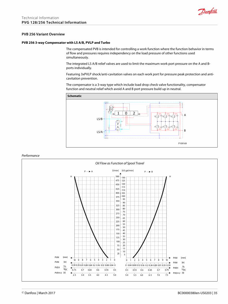
PVB 256 3-way Compensator with LS A/B, PVLP and Turbo
The compensated PVB is intended for controlling a work function where the function behavior in termsof flow and pressures requires independency on the load pressure of other functions usedsimultaneously.
The integrated LS A/B relief valves are used to limit the maximum work port pressure on the A and B-ports individually.
Featuring 3xPVLP shock/anti-cavitation valves on each work port for pressure peak protection and anti-cavitation prevention.
The compensator is a 3-way type which include load drop check valve functionality, compensatorfunction and neutral relief which avoid A and B port pressure build up in neutral.
Schematic
LS/B
LS/A
A
B
P109169
Performance
Oil Flow as Function of Spool Travel
AP
25
50
75
100
125
150
175
200
225
250
275
300
325
[mm]PVM01234567
[in]PVM00.040.080.120.160.20.240.28
PVEHUsUDC 0.50.550.60.650.7
8
0.31
0.75
910
350
375
400
0.350.39
5101520253035404550556065707580859095
100105
BP
[mm]PVM1098765
[in]PVM0.390.350.310.280.240.2
PVEHUsUDC0.70.650.60.55
4
0.16
0.5
3210
0.120.080.040
0.75
425
450
475
500
110115120125130
PVEH-U5.02.5
PVEH-U5.0 7.5
[V][V]
HH
7.06.56.05.54.54.03.53.0
[l/min] [US gal/min]
Technical InformationPVG 128/256 Technical Information
PVB 256 Variant Overview
© Danfoss | March 2017 BC00000380en-US0203 | 35
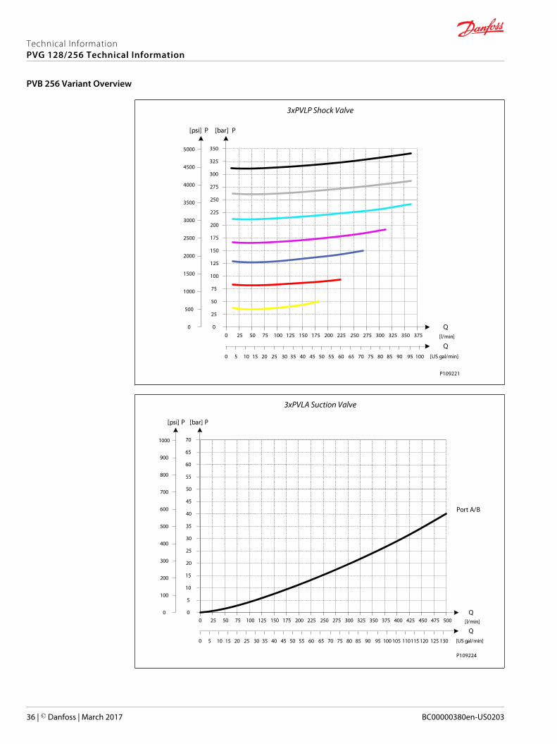
3xPVLP Shock Valve
25 50 75 100 125 150 175 200 225 250 275 300 325 [l/min]
[US gal/min]
350 375
5 10 15 20 25 30 35 40 45 50 55 60 65 70 75 80 85 90 95 100
250
225
200
175
150
125
100
75
50
25
0
Q
350
325
300
275
PP
2500
2000
1500
1000
500
0
3500
3000
4000
5000
4500
0
[psi] [bar]
0
Q
P109221
3xPVLA Suction Valve
25 50 75 100 125 150 175 200 225 250 275 300 325 [l/min]
[US gal/min]
350 375 400
5 10 15 20 25 30 35 40 45 50 55 60 65 70 75 80 85 90 95 100 105
50
45
40
35
30
25
20
15
10
5
0425 450 475 500
110115 120 125 130
Q
70
65
60
55
PP
500
400
300
200
100
0
700
600
800
1000
900
0
[psi] [bar]
0
Q
Port A/B
P109224
Technical InformationPVG 128/256 Technical Information
PVB 256 Variant Overview
36 | © Danfoss | March 2017 BC00000380en-US0203
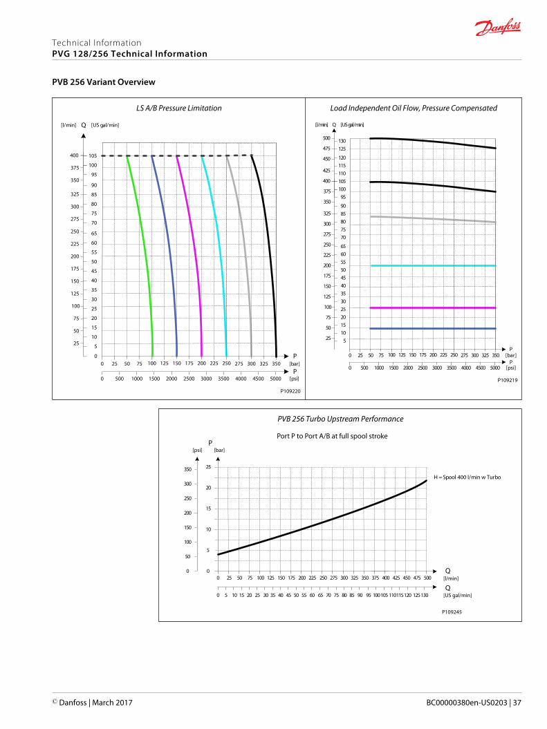
LS A/B Pressure Limitation
25
50
75
100
125
150
175
200
225
250
275
300
325
[l/min] [US gal/min]
350
375
400
5
10
15
20
25
30
35
40
45
50
55
60
65
70
75
80
85
90
95
100
105
2502252001751501251007550250
Q
350325300275P
P25002000150010005000 35003000 4000 50004500
0[bar]
[psi]
P109220
Load Independent Oil Flow, Pressure Compensated
25
50
75
100
125
150
175
200
225
250
275
300
325
[l/min] [US gal/min]
350
375
400
5101520253035404550556065
7075808590
95100105
2502252001751501251007550250
425
450
475
500
110115120
125130
Q
350325300275P
P25002000150010005000 35003000 4000 50004500
[bar]
[psi]
P109219
PVB 256 Turbo Upstream Performance
25 50 75 100 125 150 175 200 225 250 275 300 325 350 375 400
5 10 15 20 25 30 35 40 45 50 55 60 65 70 75 80 85 90 95 100105
25
20
15
10
5
0425 450 475 500
110115120 125130Q
P
250
200
150
100
50
0
350
300
0
0
Q
H = Spool 400 l/min w Turbo
[psi] [bar]
[l/min]
[US gal/min]
Port P to Port A/B at full spool stroke
P109245
Technical InformationPVG 128/256 Technical Information
PVB 256 Variant Overview
© Danfoss | March 2017 BC00000380en-US0203 | 37
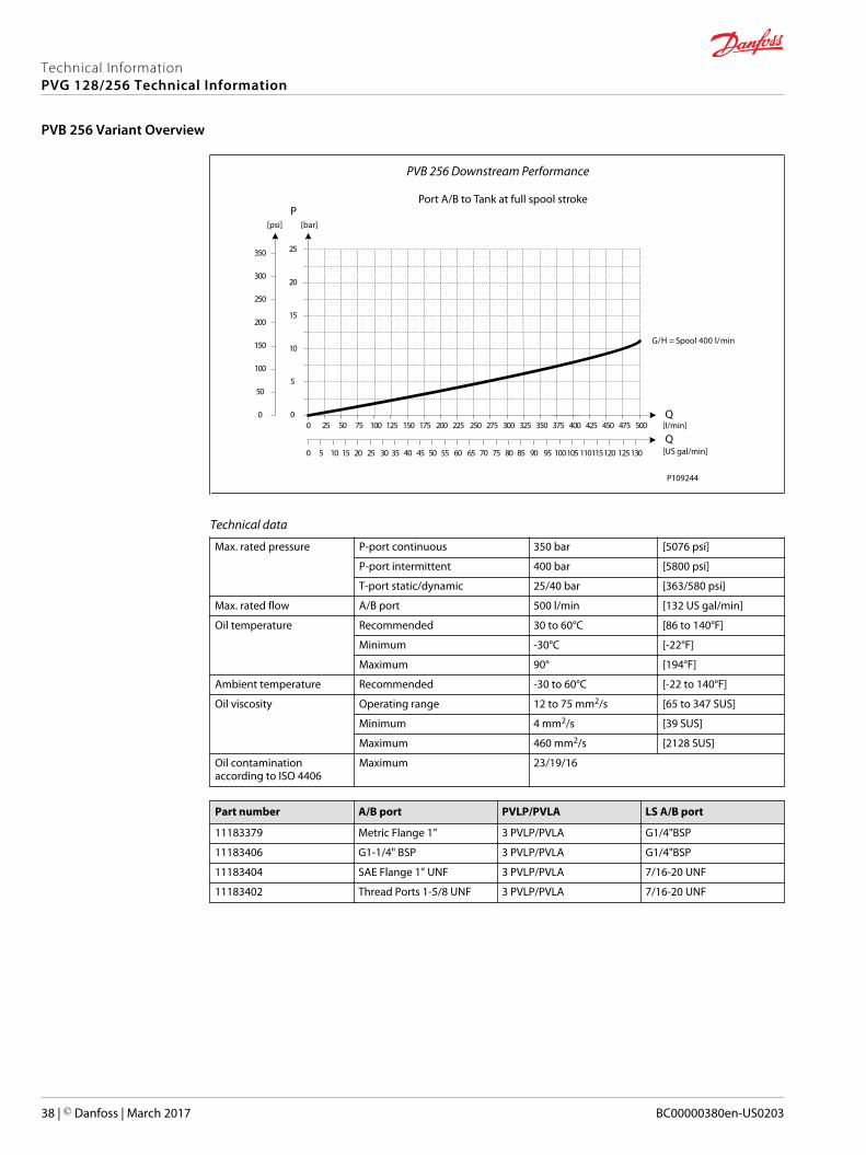
PVB 256 Downstream Performance
25 50 75 100 125 150 175 200 225 250 275 300 325 350 375 400
5 10 15 20 25 30 35 40 45 50 55 60 65 70 75 80 85 90 95 100105
25
20
15
10
5
0425 450 475 500
110115120 125130Q
P
250
200
150
100
50
0
350
300
0
0
Q
G/H = Spool 400 l/min
[psi] [bar]
[l/min]
[US gal/min]
Port A/B to Tank at full spool stroke
P109244
Technical data
Max. rated pressure P-port continuous 350 bar [5076 psi]
P-port intermittent 400 bar [5800 psi]
T-port static/dynamic 25/40 bar [363/580 psi]
Max. rated flow A/B port 500 l/min [132 US gal/min]
Oil temperature Recommended 30 to 60°C [86 to 140°F]
Minimum -30°C [-22°F]
Maximum 90° [194°F]
Ambient temperature Recommended -30 to 60°C [-22 to 140°F]
Oil viscosity Operating range 12 to 75 mm2/s [65 to 347 SUS]
Minimum 4 mm2/s [39 SUS]
Maximum 460 mm2/s [2128 SUS]
Oil contaminationaccording to ISO 4406
Maximum 23/19/16
Part number A/B port PVLP/PVLA LS A/B port
11183379 Metric Flange 1” 3 PVLP/PVLA G1/4"BSP
11183406 G1-1/4" BSP 3 PVLP/PVLA G1/4"BSP
11183404 SAE Flange 1” UNF 3 PVLP/PVLA 7/16-20 UNF
11183402 Thread Ports 1-5/8 UNF 3 PVLP/PVLA 7/16-20 UNF
Technical InformationPVG 128/256 Technical Information
PVB 256 Variant Overview
38 | © Danfoss | March 2017 BC00000380en-US0203
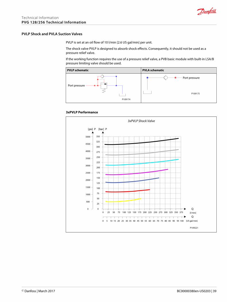
PVLP is set at an oil flow of 10 l/min [2.6 US gal/min] per unit.
The shock valve PVLP is designed to absorb shock effects. Consequently, it should not be used as apressure relief valve.
If the working function requires the use of a pressure relief valve, a PVB basic module with built-in LSA/Bpressure limiting valve should be used.
PVLP schematic PVLA schematic
P109174
Port pressure
P109175
Port pressure
3xPVLP Performance
3xPVLP Shock Valve
25 50 75 100 125 150 175 200 225 250 275 300 325 [l/min]
[US gal/min]
350 375
5 10 15 20 25 30 35 40 45 50 55 60 65 70 75 80 85 90 95 100
250
225
200
175
150
125
100
75
50
25
0
Q
350
325
300
275
PP
2500
2000
1500
1000
500
0
3500
3000
4000
5000
4500
0
[psi] [bar]
0
Q
P109221
Technical InformationPVG 128/256 Technical Information
PVLP Shock and PVLA Suction Valves
© Danfoss | March 2017 BC00000380en-US0203 | 39
3xPVLA Suction Valve
25 50 75 100 125 150 175 200 225 250 275 300 325 [l/min]
[US gal/min]
350 375 400
5 10 15 20 25 30 35 40 45 50 55 60 65 70 75 80 85 90 95 100 105
50
45
40
35
30
25
20
15
10
5
0425 450 475 500
110115 120 125 130
Q
70
65
60
55
PP
500
400
300
200
100
0
700
600
800
1000
900
0
[psi] [bar]
0
Q
Port A/B
P109224
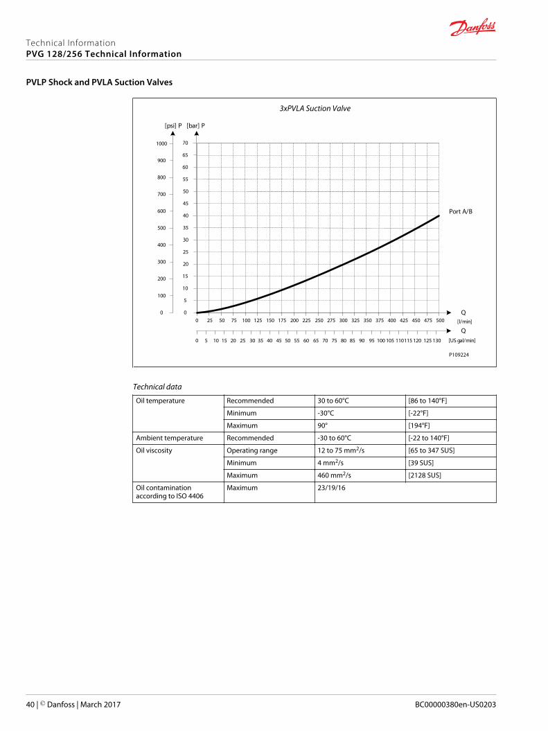
Technical data
Oil temperature Recommended 30 to 60°C [86 to 140°F]
Minimum -30°C [-22°F]
Maximum 90° [194°F]
Ambient temperature Recommended -30 to 60°C [-22 to 140°F]
Oil viscosity Operating range 12 to 75 mm2/s [65 to 347 SUS]
Minimum 4 mm2/s [39 SUS]
Maximum 460 mm2/s [2128 SUS]
Oil contaminationaccording to ISO 4406
Maximum 23/19/16
Technical InformationPVG 128/256 Technical Information
PVLP Shock and PVLA Suction Valves
40 | © Danfoss | March 2017 BC00000380en-US0203
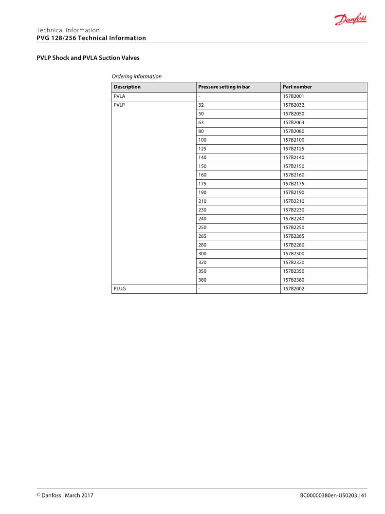
Ordering information
Description Pressure setting in bar Part number
PVLA - 157B2001
PVLP 32 157B2032
50 157B2050
63 157B2063
80 157B2080
100 157B2100
125 157B2125
140 157B2140
150 157B2150
160 157B2160
175 157B2175
190 157B2190
210 157B2210
230 157B2230
240 157B2240
250 157B2250
265 157B2265
280 157B2280
300 157B2300
320 157B2320
350 157B2350
380 157B2380
PLUG - 157B2002
Technical InformationPVG 128/256 Technical Information
PVLP Shock and PVLA Suction Valves
© Danfoss | March 2017 BC00000380en-US0203 | 41

PVBS 128/256 Dimensions (mm)
230 83.5 30
P109176
PVBS Variant Overview for PVB 128/256
Symbol Description
P109177
Standard FC spools closed neutral position• 4-way, 3-position• Closed neutral position• Flow Control AB• Spools from 65 to 240 l/min only to be used with PVB 128• Spools above 240 l/min to be used with PVB 256
P109178
Standard FC spools Throttled open neutral position• 4-way, 3-position• Throttled open neutral position• Flow Control AB• Spools from 65 to 240 l/min to be used with PVB 128• Spools above 240 l/min only to be used with PVB 256
P109179
Standard FC spools single acting closed neutral position• 3-way, 3-position• Closed neutral position• Flow Control B• Spools from 65 to 240 l/min to be used with PVB 128• Spools above 240 l/min only to be used with PVB 256
P109180
Standard FC spools float A closed neutral position• 4-way, 3-position• Closed neutral position• Flow Control AB• Float P→A→F• Spools from 65 to 240 l/min to be used with PVB 128• Spools above 240 l/min only to be used with PVB 256
Technical InformationPVG 128/256 Technical Information
PVBS PVE Electric Activation and/or Mechanical
42 | © Danfoss | March 2017 BC00000380en-US0203
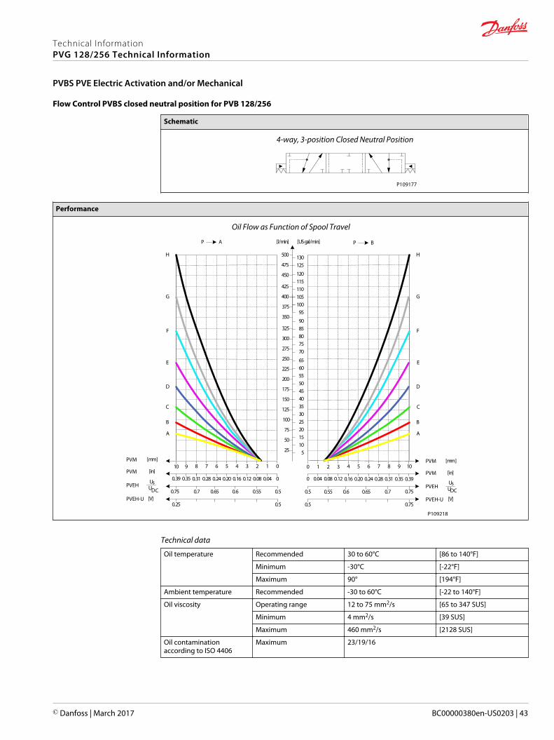
Flow Control PVBS closed neutral position for PVB 128/256
Schematic
4-way, 3-position Closed Neutral Position
P109177
Performance
Oil Flow as Function of Spool Travel
AP
25
50
75
100
125
150
175
200
225
250
275
300
325
[l/min] [US gal/min]
[mm]PVM01234567
[in]PVM00.040.080.120.160.200.240.28
PVEHUsUDC 0.50.550.60.650.7
8
0.31
0.75
910
350
375
400
0.350.39
5101520253035404550556065
7075808590
95100105
BP
[mm]PVM1098765
[in]PVM0.390.350.310.280.240.20
PVEHUsUDC0.70.650.60.55
4
0.16
0.5
3210
0.120.080.040
0.75
425
450
475
500
110115120
125130
PVEH-U0.50.25
PVEH-U0.5 0.75
[V][V]
A
B
C
D
E
F
G
H
A
B
C
D
E
F
G
H
P109218
Technical data
Oil temperature Recommended 30 to 60°C [86 to 140°F]
Minimum -30°C [-22°F]
Maximum 90° [194°F]
Ambient temperature Recommended -30 to 60°C [-22 to 140°F]
Oil viscosity Operating range 12 to 75 mm2/s [65 to 347 SUS]
Minimum 4 mm2/s [39 SUS]
Maximum 460 mm2/s [2128 SUS]
Oil contaminationaccording to ISO 4406
Maximum 23/19/16
Technical InformationPVG 128/256 Technical Information
PVBS PVE Electric Activation and/or Mechanical
© Danfoss | March 2017 BC00000380en-US0203 | 43
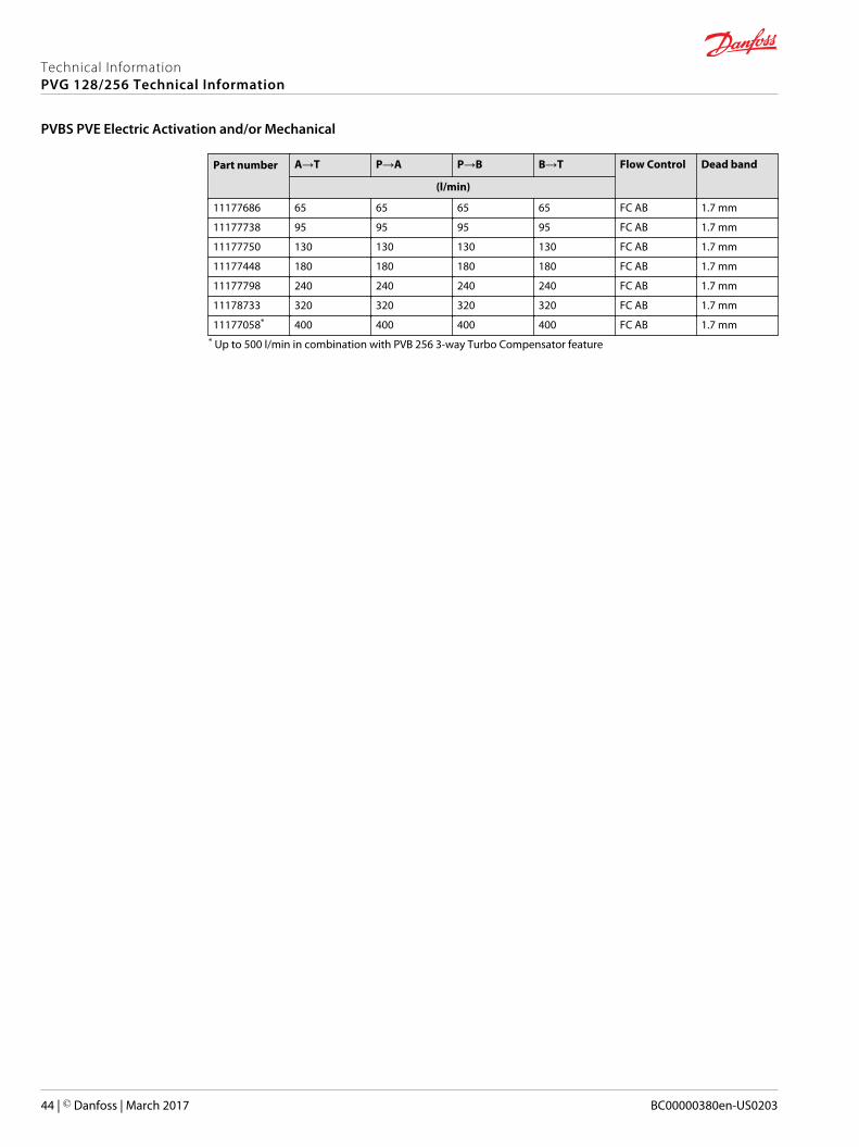
Part number A→T P→A P→B B→T Flow Control Dead band
(l/min)
11177686 65 65 65 65 FC AB 1.7 mm
11177738 95 95 95 95 FC AB 1.7 mm
11177750 130 130 130 130 FC AB 1.7 mm
11177448 180 180 180 180 FC AB 1.7 mm
11177798 240 240 240 240 FC AB 1.7 mm
11178733 320 320 320 320 FC AB 1.7 mm
11177058* 400 400 400 400 FC AB 1.7 mm* Up to 500 l/min in combination with PVB 256 3-way Turbo Compensator feature
Technical InformationPVG 128/256 Technical Information
PVBS PVE Electric Activation and/or Mechanical
44 | © Danfoss | March 2017 BC00000380en-US0203
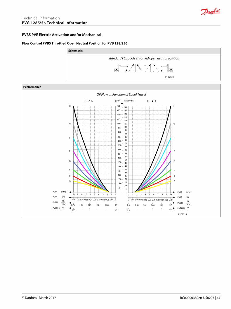
Flow Control PVBS Throttled Open Neutral Position for PVB 128/256
Schematic
Standard FC spools Throttled open neutral position
P109178
Performance
Oil Flow as Function of Spool Travel
AP
25
50
75
100
125
150
175
200
225
250
275
300
325
[l/min] [US gal/min]
[mm]PVM01234567
[in]PVM00.040.080.120.160.200.240.28
PVEHUsUDC 0.50.550.60.650.7
8
0.31
0.75
910
350
375
400
0.350.39
5101520253035404550556065
7075808590
95100105
BP
[mm]PVM1098765
[in]PVM0.390.350.310.280.240.20
PVEHUsUDC0.70.650.60.55
4
0.16
0.5
3210
0.120.080.040
0.75
425
450
475
500
110115120
125130
PVEH-U0.50.25
PVEH-U0.5 0.75
[V][V]
A
B
C
D
E
F
G
H
A
B
C
D
E
F
G
H
P109218
Technical InformationPVG 128/256 Technical Information
PVBS PVE Electric Activation and/or Mechanical
© Danfoss | March 2017 BC00000380en-US0203 | 45
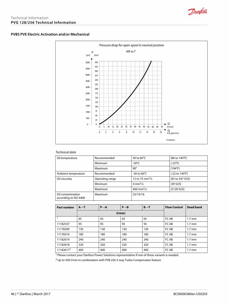
Pressure drop for open spool in neutral position
50454035302520151050 70656055Q
Q1086420 1412 1816
250
225
200
175
150
125
100
75
50
25
0
350
325
300
275
P
2500
2000
1500
1000
500
0
3500
3000
4000
5000
4500
A/B to T[psi] [bar]
[l/min]
[US gal/min]
P109253
Technical data
Oil temperature Recommended 30 to 60°C [86 to 140°F]
Minimum -30°C [-22°F]
Maximum 90° [194°F]
Ambient temperature Recommended -30 to 60°C [-22 to 140°F]
Oil viscosity Operating range 12 to 75 mm2/s [65 to 347 SUS]
Minimum 4 mm2/s [39 SUS]
Maximum 460 mm2/s [2128 SUS]
Oil contaminationaccording to ISO 4406
Maximum 23/19/16
Part number A→T P→A P→B B→T Flow Control Dead band
(l/min)1 65 65 65 65 FC AB 1.7 mm
11182537 95 95 95 95 FC AB 1.7 mm
11178290 130 130 130 130 FC AB 1.7 mm
11178310 180 180 180 180 FC AB 1.7 mm
11182619 240 240 240 240 FC AB 1.7 mm
11182618 320 320 320 320 FC AB 1.7 mm
111826172 400 400 400 400 FC AB 1.7 mm1 Please contact your Danfoss Power Solutions representative if one of these variants is needed.2 Up to 500 l/min in combination with PVB 256 3-way Turbo Compensator feature
Technical InformationPVG 128/256 Technical Information
PVBS PVE Electric Activation and/or Mechanical
46 | © Danfoss | March 2017 BC00000380en-US0203
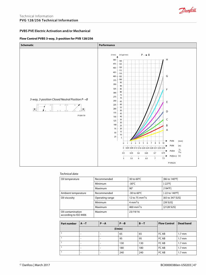
Flow Control PVBS 3-way, 3-position for PVB 128/256
Schematic Performance
3-way, 3-position Closed Neutral Position P→B
P109179
25
50
75
100
125
150
175
200
225
250
275
300
325
[l/min] [US gal/min]
350
375
400
5101520253035404550556065
7075808590
95100105
BP
PVM1098765
PVM0.390.350.310.280.240.20
PVEHUs
UDC0.70.650.60.55
4
0.16
0.5
3210
0.120.080.040
0.75
425
450
475
500
110115120
125130
PVEH-U
A
B
C
D
E
F
G
H
76.565.55 7.5
P109225
[mm]
[in]
[V]
Technical data
Oil temperature Recommended 30 to 60°C [86 to 140°F]
Minimum -30°C [-22°F]
Maximum 90° [194°F]
Ambient temperature Recommended -30 to 60°C [-22 to 140°F]
Oil viscosity Operating range 12 to 75 mm2/s [65 to 347 SUS]
Minimum 4 mm2/s [39 SUS]
Maximum 460 mm2/s [2128 SUS]
Oil contaminationaccording to ISO 4406
Maximum 23/19/16
Part number A→T P→A P→B B→T Flow Control Dead band
(l/min)1 - - 65 65 FC AB 1.7 mm1 - - 95 95 FC AB 1.7 mm1 - - 130 130 FC AB 1.7 mm1 - - 180 180 FC AB 1.7 mm1 - - 240 240 FC AB 1.7 mm
Technical InformationPVG 128/256 Technical Information
PVBS PVE Electric Activation and/or Mechanical
© Danfoss | March 2017 BC00000380en-US0203 | 47
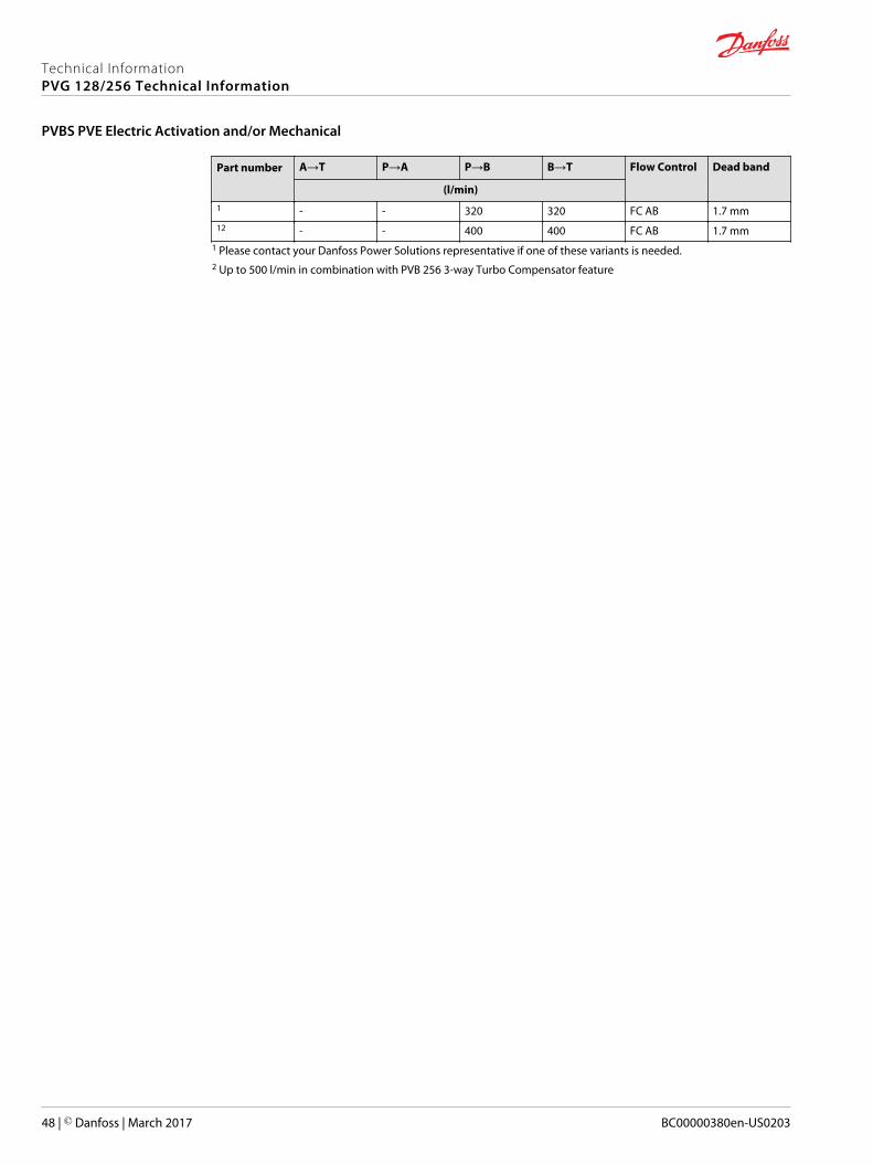
Part number A→T P→A P→B B→T Flow Control Dead band
(l/min)1 - - 320 320 FC AB 1.7 mm12 - - 400 400 FC AB 1.7 mm
1 Please contact your Danfoss Power Solutions representative if one of these variants is needed.2 Up to 500 l/min in combination with PVB 256 3-way Turbo Compensator feature
Technical InformationPVG 128/256 Technical Information
PVBS PVE Electric Activation and/or Mechanical
48 | © Danfoss | March 2017 BC00000380en-US0203
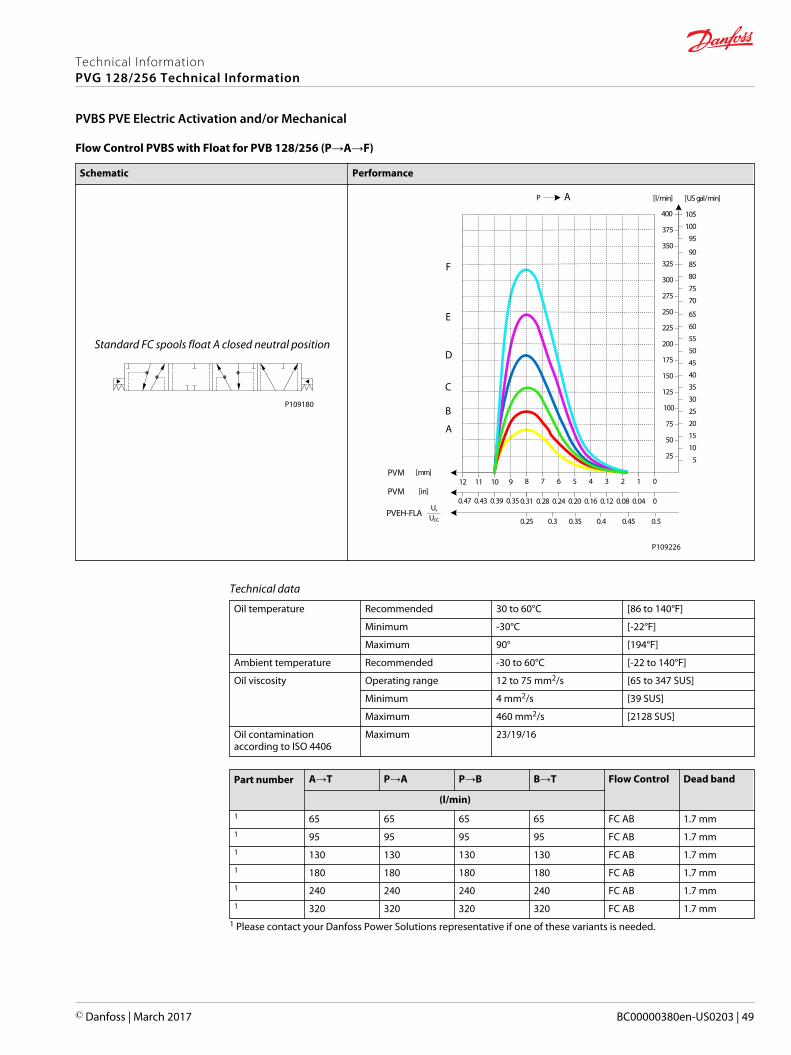
Flow Control PVBS with Float for PVB 128/256 (P→A→F)
Schematic Performance
Standard FC spools float A closed neutral position
P109180
AP
25
50
75
100
125
150
175
200
225
250
275
300
325
[l/min] [US gal/min]
[mm]PVM01234567
[in]PVM00.040.080.120.160.200.240.28
PVEH-FLAUs
UDC 0.50.450.40.350.3
8
0.31
9101112
350
375
400
0.350.390.430.47
5
10
15
20
25
30
35
40
45
50
55
60
65
70
75
80
85
90
95
100
105
A
B
C
D
E
F
0.25
P109226
Technical data
Oil temperature Recommended 30 to 60°C [86 to 140°F]
Minimum -30°C [-22°F]
Maximum 90° [194°F]
Ambient temperature Recommended -30 to 60°C [-22 to 140°F]
Oil viscosity Operating range 12 to 75 mm2/s [65 to 347 SUS]
Minimum 4 mm2/s [39 SUS]
Maximum 460 mm2/s [2128 SUS]
Oil contaminationaccording to ISO 4406
Maximum 23/19/16
Part number A→T P→A P→B B→T Flow Control Dead band
(l/min)1 65 65 65 65 FC AB 1.7 mm1 95 95 95 95 FC AB 1.7 mm1 130 130 130 130 FC AB 1.7 mm1 180 180 180 180 FC AB 1.7 mm1 240 240 240 240 FC AB 1.7 mm1 320 320 320 320 FC AB 1.7 mm
1 Please contact your Danfoss Power Solutions representative if one of these variants is needed.
Technical InformationPVG 128/256 Technical Information
PVBS PVE Electric Activation and/or Mechanical
© Danfoss | March 2017 BC00000380en-US0203 | 49
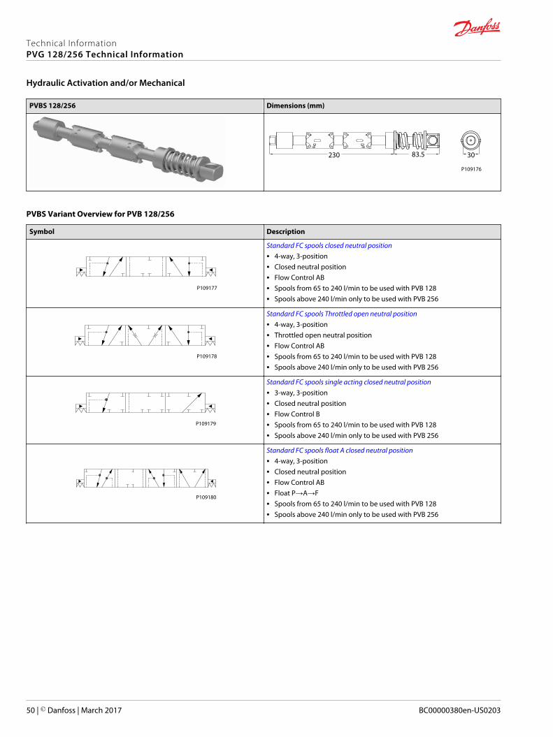
PVBS 128/256 Dimensions (mm)
230 83.5 30
P109176
PVBS Variant Overview for PVB 128/256
Symbol Description
P109177
Standard FC spools closed neutral position• 4-way, 3-position• Closed neutral position• Flow Control AB• Spools from 65 to 240 l/min to be used with PVB 128• Spools above 240 l/min only to be used with PVB 256
P109178
Standard FC spools Throttled open neutral position• 4-way, 3-position• Throttled open neutral position• Flow Control AB• Spools from 65 to 240 l/min to be used with PVB 128• Spools above 240 l/min only to be used with PVB 256
P109179
Standard FC spools single acting closed neutral position• 3-way, 3-position• Closed neutral position• Flow Control B• Spools from 65 to 240 l/min to be used with PVB 128• Spools above 240 l/min only to be used with PVB 256
P109180
Standard FC spools float A closed neutral position• 4-way, 3-position• Closed neutral position• Flow Control AB• Float P→A→F• Spools from 65 to 240 l/min to be used with PVB 128• Spools above 240 l/min only to be used with PVB 256
Technical InformationPVG 128/256 Technical Information
Hydraulic Activation and/or Mechanical
50 | © Danfoss | March 2017 BC00000380en-US0203

Flow Control PVBS closed neutral position for PVB 128/256
Schematic
4-way, 3-position Closed Neutral Position
P109177
Performance
Oil Flow as Function of Spool Travel
AP
25
50
75
100
125
150
175
200
225
250
275
300
325
[l/min] [US gal/min]
[mm]PVM01234567
[in]PVM00.040.080.120.160.200.240.28
PVEHUsUDC 0.50.550.60.650.7
8
0.31
0.75
910
350
375
400
0.350.39
5101520253035404550556065
7075808590
95100105
BP
[mm]PVM1098765
[in]PVM0.390.350.310.280.240.20
PVEHUsUDC0.70.650.60.55
4
0.16
0.5
3210
0.120.080.040
0.75
425
450
475
500
110115120
125130
PVEH-U0.50.25
PVEH-U0.5 0.75
[V][V]
A
B
C
D
E
F
G
H
A
B
C
D
E
F
G
H
P109218
Technical data
Oil temperature Recommended 30 to 60°C [86 to 140°F]
Minimum -30°C [-22°F]
Maximum 90° [194°F]
Ambient temperature Recommended -30 to 60°C [-22 to 140°F]
Oil viscosity Operating range 12 to 75 mm2/s [65 to 347 SUS]
Minimum 4 mm2/s [39 SUS]
Maximum 460 mm2/s [2128 SUS]
Oil contaminationaccording to ISO 4406
Maximum 23/19/16
Technical InformationPVG 128/256 Technical Information
Hydraulic Activation and/or Mechanical
© Danfoss | March 2017 BC00000380en-US0203 | 51
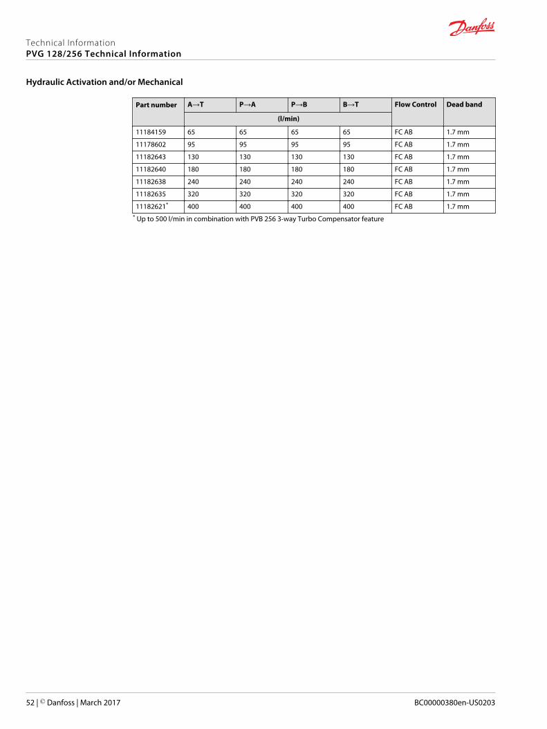
Part number A→T P→A P→B B→T Flow Control Dead band
(l/min)
11184159 65 65 65 65 FC AB 1.7 mm
11178602 95 95 95 95 FC AB 1.7 mm
11182643 130 130 130 130 FC AB 1.7 mm
11182640 180 180 180 180 FC AB 1.7 mm
11182638 240 240 240 240 FC AB 1.7 mm
11182635 320 320 320 320 FC AB 1.7 mm
11182621* 400 400 400 400 FC AB 1.7 mm* Up to 500 l/min in combination with PVB 256 3-way Turbo Compensator feature
Technical InformationPVG 128/256 Technical Information
Hydraulic Activation and/or Mechanical
52 | © Danfoss | March 2017 BC00000380en-US0203
Flow Control PVBS Throttled open neutral position for PVB 128/256
Schematic
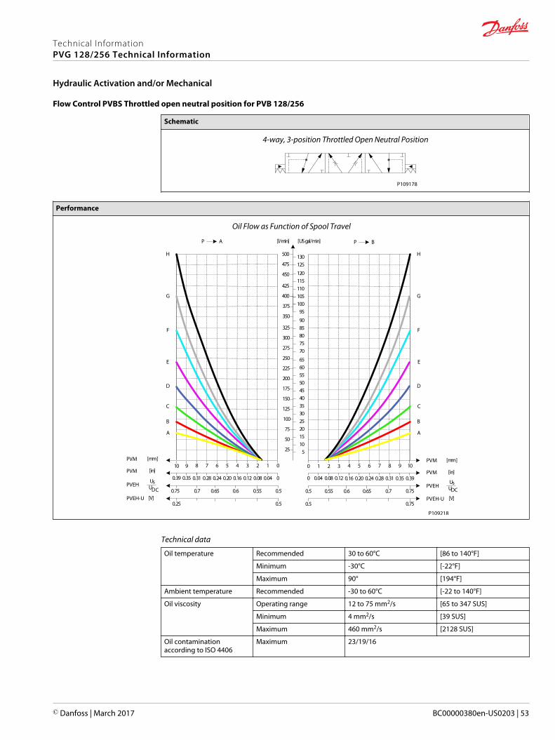
4-way, 3-position Throttled Open Neutral Position
P109178
Performance
Oil Flow as Function of Spool Travel
AP
25
50
75
100
125
150
175
200
225
250
275
300
325
[l/min] [US gal/min]
[mm]PVM01234567
[in]PVM00.040.080.120.160.200.240.28
PVEHUsUDC 0.50.550.60.650.7
8
0.31
0.75
910
350
375
400
0.350.39
5101520253035404550556065
7075808590
95100105
BP
[mm]PVM1098765
[in]PVM0.390.350.310.280.240.20
PVEHUsUDC0.70.650.60.55
4
0.16
0.5
3210
0.120.080.040
0.75
425
450
475
500
110115120
125130
PVEH-U0.50.25
PVEH-U0.5 0.75
[V][V]
A
B
C
D
E
F
G
H
A
B
C
D
E
F
G
H
P109218
Technical data
Oil temperature Recommended 30 to 60°C [86 to 140°F]
Minimum -30°C [-22°F]
Maximum 90° [194°F]
Ambient temperature Recommended -30 to 60°C [-22 to 140°F]
Oil viscosity Operating range 12 to 75 mm2/s [65 to 347 SUS]
Minimum 4 mm2/s [39 SUS]
Maximum 460 mm2/s [2128 SUS]
Oil contaminationaccording to ISO 4406
Maximum 23/19/16
Technical InformationPVG 128/256 Technical Information
Hydraulic Activation and/or Mechanical
© Danfoss | March 2017 BC00000380en-US0203 | 53
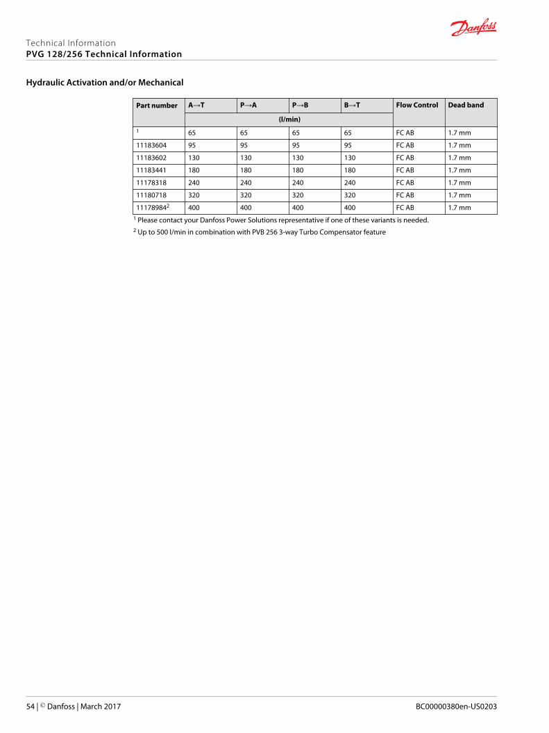
Part number A→T P→A P→B B→T Flow Control Dead band
(l/min)1 65 65 65 65 FC AB 1.7 mm
11183604 95 95 95 95 FC AB 1.7 mm
11183602 130 130 130 130 FC AB 1.7 mm
11183441 180 180 180 180 FC AB 1.7 mm
11178318 240 240 240 240 FC AB 1.7 mm
11180718 320 320 320 320 FC AB 1.7 mm
111789842 400 400 400 400 FC AB 1.7 mm1 Please contact your Danfoss Power Solutions representative if one of these variants is needed.2 Up to 500 l/min in combination with PVB 256 3-way Turbo Compensator feature
Technical InformationPVG 128/256 Technical Information
Hydraulic Activation and/or Mechanical
54 | © Danfoss | March 2017 BC00000380en-US0203
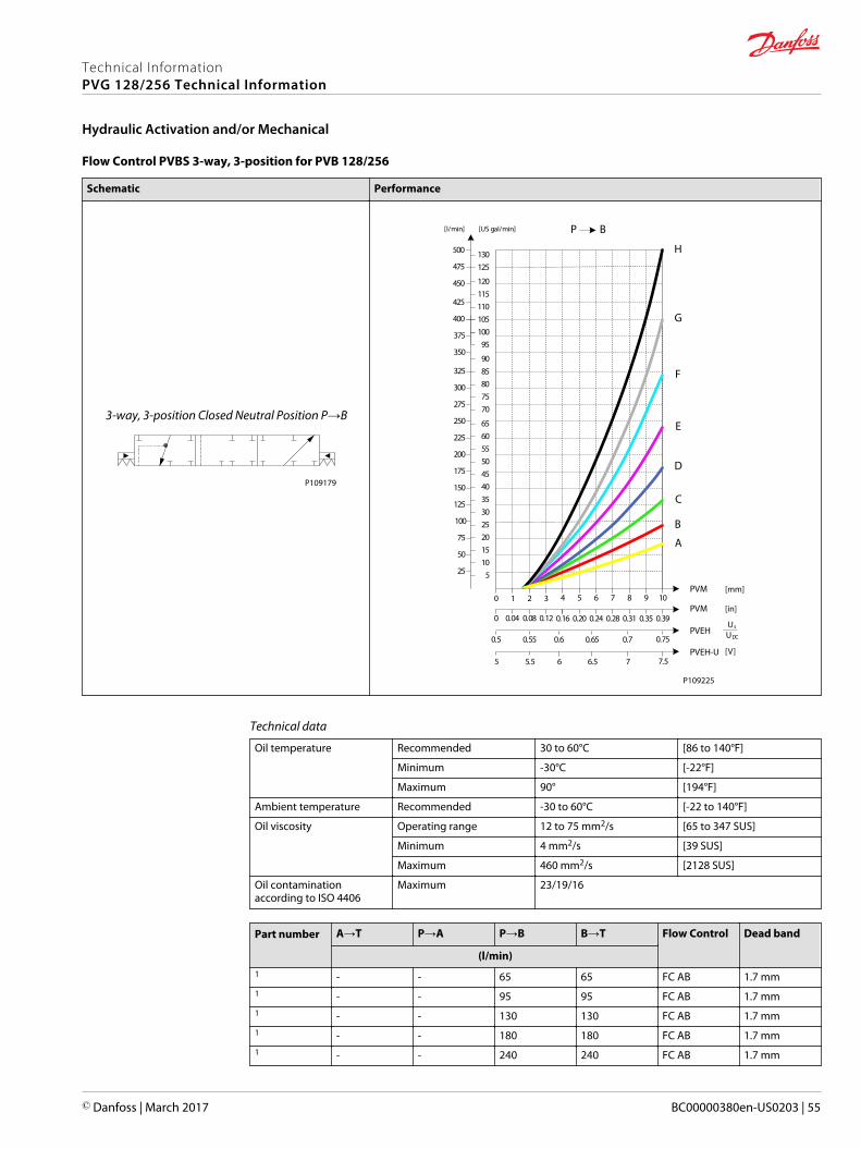
Flow Control PVBS 3-way, 3-position for PVB 128/256
Schematic Performance
3-way, 3-position Closed Neutral Position P→B
P109179
25
50
75
100
125
150
175
200
225
250
275
300
325
[l/min] [US gal/min]
350
375
400
5101520253035404550556065
7075808590
95100105
BP
PVM1098765
PVM0.390.350.310.280.240.20
PVEHUs
UDC0.70.650.60.55
4
0.16
0.5
3210
0.120.080.040
0.75
425
450
475
500
110115120
125130
PVEH-U
A
B
C
D
E
F
G
H
76.565.55 7.5
P109225
[mm]
[in]
[V]
Technical data
Oil temperature Recommended 30 to 60°C [86 to 140°F]
Minimum -30°C [-22°F]
Maximum 90° [194°F]
Ambient temperature Recommended -30 to 60°C [-22 to 140°F]
Oil viscosity Operating range 12 to 75 mm2/s [65 to 347 SUS]
Minimum 4 mm2/s [39 SUS]
Maximum 460 mm2/s [2128 SUS]
Oil contaminationaccording to ISO 4406
Maximum 23/19/16
Part number A→T P→A P→B B→T Flow Control Dead band
(l/min)1 - - 65 65 FC AB 1.7 mm1 - - 95 95 FC AB 1.7 mm1 - - 130 130 FC AB 1.7 mm1 - - 180 180 FC AB 1.7 mm1 - - 240 240 FC AB 1.7 mm
Technical InformationPVG 128/256 Technical Information
Hydraulic Activation and/or Mechanical
© Danfoss | March 2017 BC00000380en-US0203 | 55
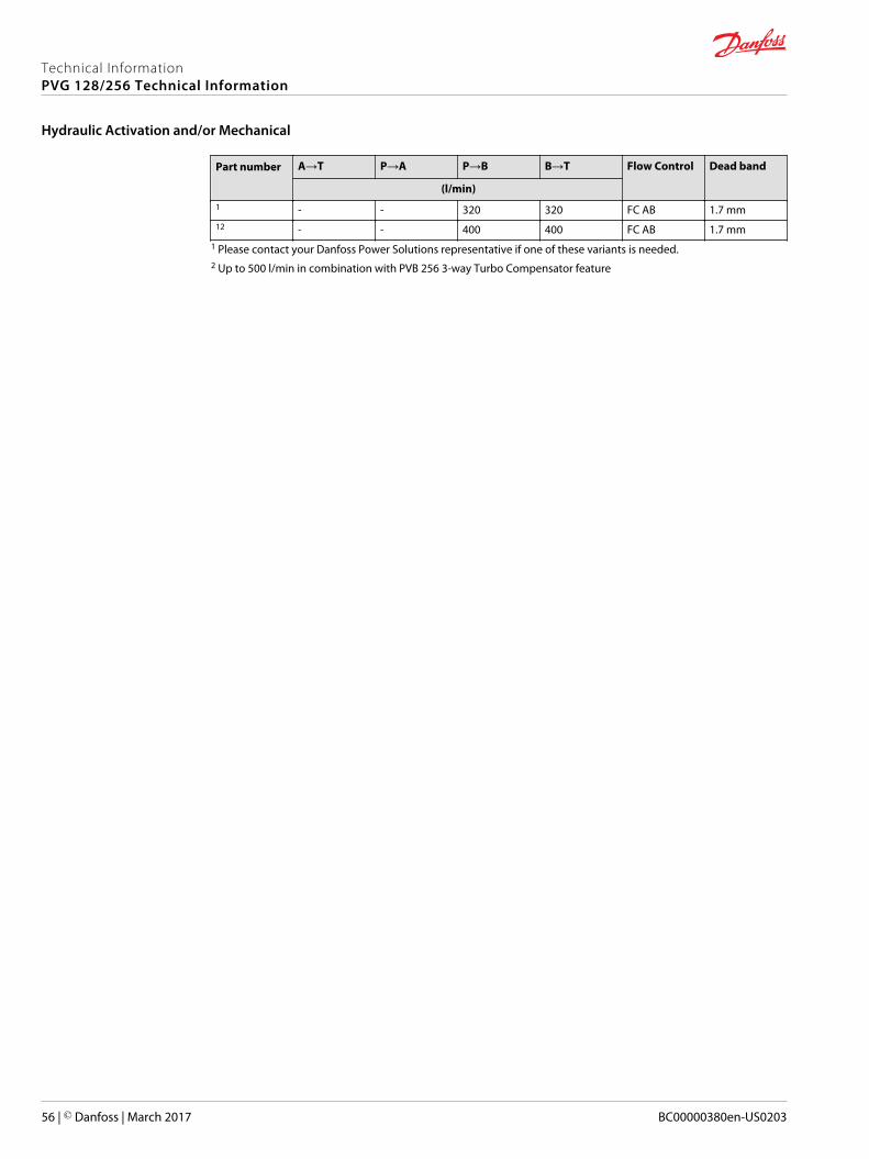
Part number A→T P→A P→B B→T Flow Control Dead band
(l/min)1 - - 320 320 FC AB 1.7 mm12 - - 400 400 FC AB 1.7 mm
1 Please contact your Danfoss Power Solutions representative if one of these variants is needed.2 Up to 500 l/min in combination with PVB 256 3-way Turbo Compensator feature
Technical InformationPVG 128/256 Technical Information
Hydraulic Activation and/or Mechanical
56 | © Danfoss | March 2017 BC00000380en-US0203
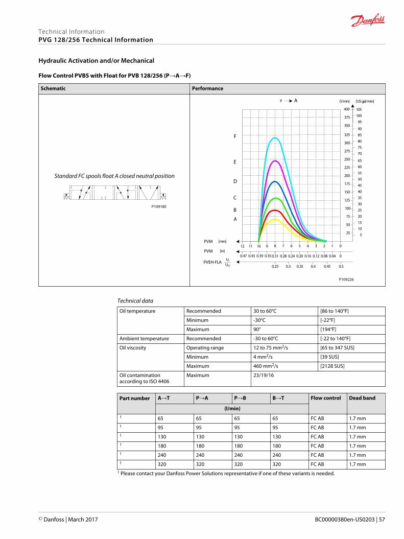
Flow Control PVBS with Float for PVB 128/256 (P→A→F)
Schematic Performance
Standard FC spools float A closed neutral position
P109180
AP
25
50
75
100
125
150
175
200
225
250
275
300
325
[l/min] [US gal/min]
[mm]PVM01234567
[in]PVM00.040.080.120.160.200.240.28
PVEH-FLAUs
UDC 0.50.450.40.350.3
8
0.31
9101112
350
375
400
0.350.390.430.47
5
10
15
20
25
30
35
40
45
50
55
60
65
70
75
80
85
90
95
100
105
A
B
C
D
E
F
0.25
P109226
Technical data
Oil temperature Recommended 30 to 60°C [86 to 140°F]
Minimum -30°C [-22°F]
Maximum 90° [194°F]
Ambient temperature Recommended -30 to 60°C [-22 to 140°F]
Oil viscosity Operating range 12 to 75 mm2/s [65 to 347 SUS]
Minimum 4 mm2/s [39 SUS]
Maximum 460 mm2/s [2128 SUS]
Oil contaminationaccording to ISO 4406
Maximum 23/19/16
Part number A→T P→A P→B B→T Flow control Dead band
(l/min)1 65 65 65 65 FC AB 1.7 mm1 95 95 95 95 FC AB 1.7 mm1 130 130 130 130 FC AB 1.7 mm1 180 180 180 180 FC AB 1.7 mm1 240 240 240 240 FC AB 1.7 mm1 320 320 320 320 FC AB 1.7 mm
1 Please contact your Danfoss Power Solutions representative if one of these variants is needed.
Technical InformationPVG 128/256 Technical Information
Hydraulic Activation and/or Mechanical
© Danfoss | March 2017 BC00000380en-US0203 | 57
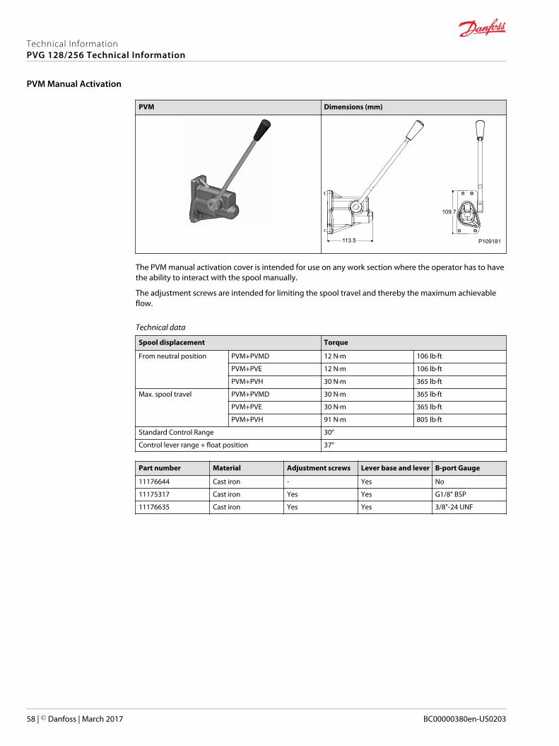
PVM Dimensions (mm)
113.5
109.7
P109181
The PVM manual activation cover is intended for use on any work section where the operator has to havethe ability to interact with the spool manually.
The adjustment screws are intended for limiting the spool travel and thereby the maximum achievableflow.
Technical data
Spool displacement Torque
From neutral position PVM+PVMD 12 N·m 106 lb·ft
PVM+PVE 12 N·m 106 lb·ft
PVM+PVH 30 N·m 365 lb·ft
Max. spool travel PVM+PVMD 30 N·m 365 lb·ft
PVM+PVE 30 N·m 365 lb·ft
PVM+PVH 91 N·m 805 lb·ft
Standard Control Range 30°
Control lever range + float position 37°
Part number Material Adjustment screws Lever base and lever B-port Gauge
11176644 Cast iron - Yes No
11175317 Cast iron Yes Yes G1/8" BSP
11176635 Cast iron Yes Yes 3/8"-24 UNF
Technical InformationPVG 128/256 Technical Information
PVM Manual Activation
58 | © Danfoss | March 2017 BC00000380en-US0203
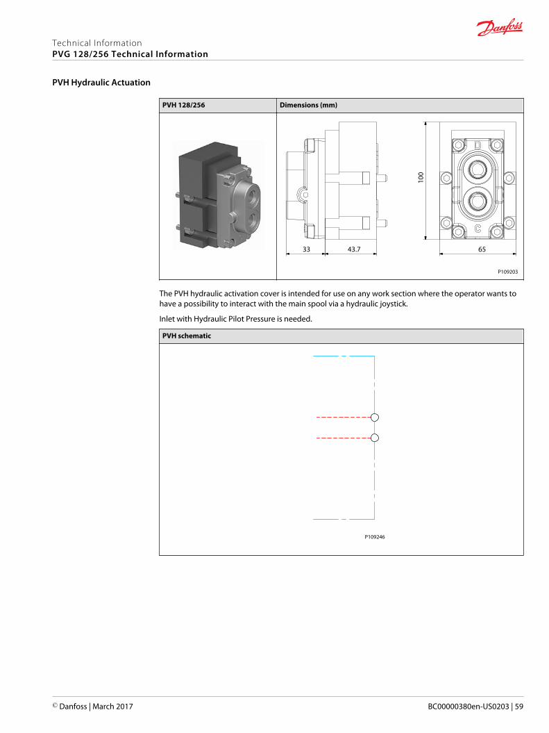
PVH 128/256 Dimensions (mm)
33 43.7
100
65
P109203
The PVH hydraulic activation cover is intended for use on any work section where the operator wants tohave a possibility to interact with the main spool via a hydraulic joystick.
Inlet with Hydraulic Pilot Pressure is needed.
PVH schematic
P109246
Technical InformationPVG 128/256 Technical Information
PVH Hydraulic Actuation
© Danfoss | March 2017 BC00000380en-US0203 | 59
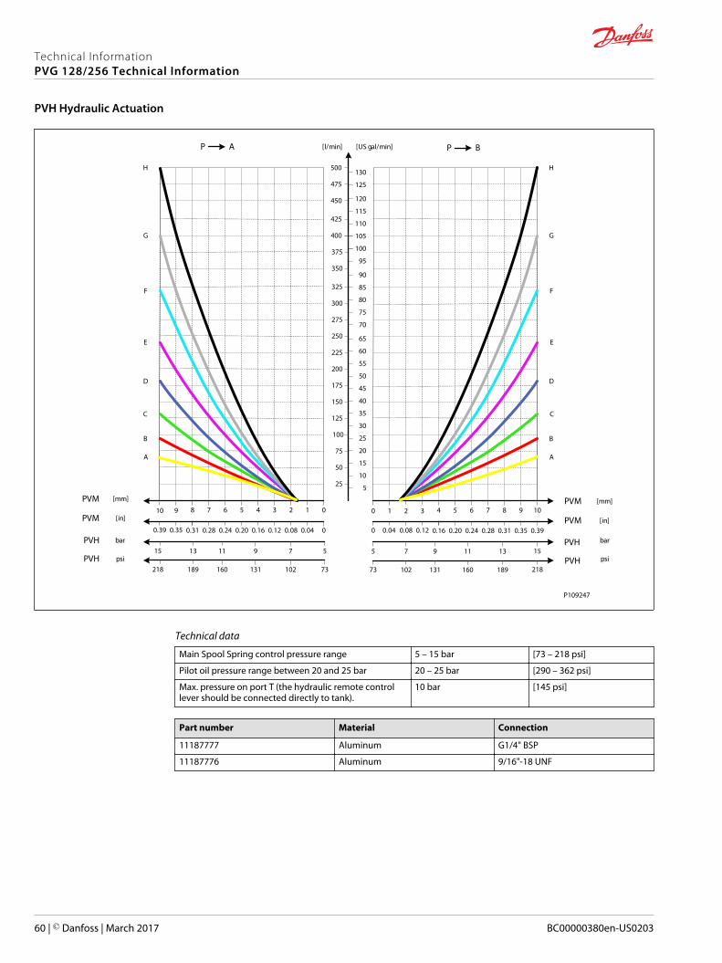
AP
25
50
75
100
125
150
175
200
225
250
275
300
325
[l/min] [US gal/min]
[mm]PVM01234567
[in]PVM00.040.080.120.160.200.240.28
PVH barbar5791113
8
0.31
15
910
350
375
400
0.350.39
5
10
15
20
25
30
35
40
45
50
55
60
65
70
75
80
85
90
95
100
105
BP
[mm]PVM1098765
[in]PVM0.390.350.310.280.240.20
PVH131197
4
0.16
5
3210
0.120.080.040
15
425
450
475
500
110
115
120
125
130
A
B
C
D
E
F
G
H
A
B
C
D
E
F
G
H
barbar
PVH psipsi73102131160189218
PVH18916013110273 218
psipsi
P109247
Technical data
Main Spool Spring control pressure range 5 – 15 bar [73 – 218 psi]
Pilot oil pressure range between 20 and 25 bar 20 – 25 bar [290 – 362 psi]
Max. pressure on port T (the hydraulic remote controllever should be connected directly to tank).
10 bar [145 psi]
Part number Material Connection
11187777 Aluminum G1/4" BSP
11187776 Aluminum 9/16"-18 UNF
Technical InformationPVG 128/256 Technical Information
PVH Hydraulic Actuation
60 | © Danfoss | March 2017 BC00000380en-US0203
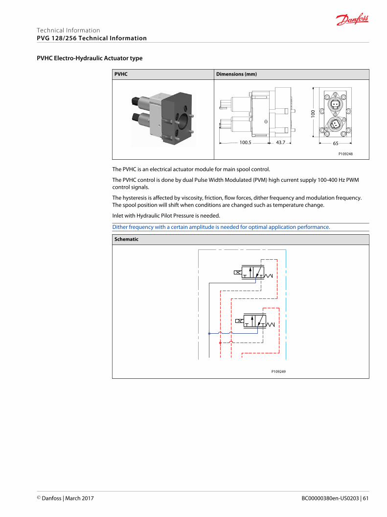
PVHC Dimensions (mm)
65
100
43.7100.5
P109248
The PVHC is an electrical actuator module for main spool control.
The PVHC control is done by dual Pulse Width Modulated (PVM) high current supply 100-400 Hz PWMcontrol signals.
The hysteresis is affected by viscosity, friction, flow forces, dither frequency and modulation frequency.The spool position will shift when conditions are changed such as temperature change.
Inlet with Hydraulic Pilot Pressure is needed.
Dither frequency with a certain amplitude is needed for optimal application performance.
Schematic
P109249
Technical InformationPVG 128/256 Technical Information
PVHC Electro-Hydraulic Actuator type
© Danfoss | March 2017 BC00000380en-US0203 | 61
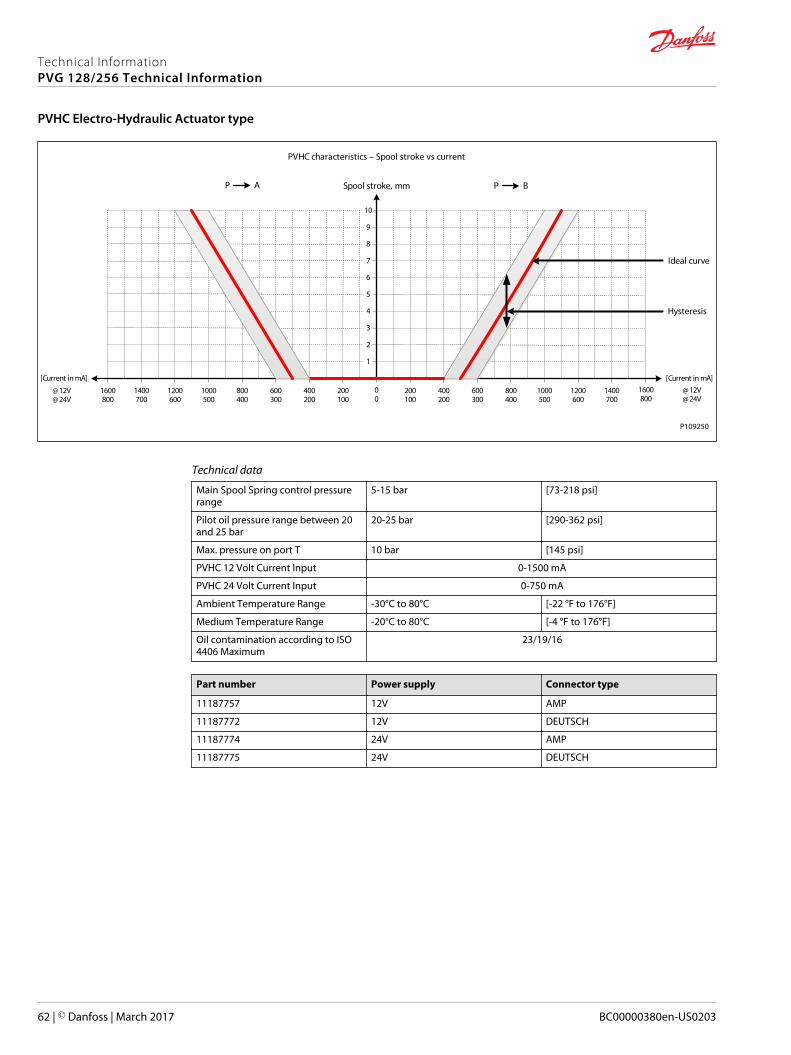
AP
1
2
3
4
5
6
7
8
9
10
00
200100
400200
600300
800400
1000500
BP
800400
600300
400200
200100
1000500
[Current in mA][Current in mA]
@12V@24V
@12V@24V
1600800
1400700
1200600
1200600
1600800
1400700
Spool stroke, mm
PVHC characteristics – Spool stroke vs current
Ideal curve
Hysteresis
P109250
Technical data
Main Spool Spring control pressurerange
5-15 bar [73-218 psi]
Pilot oil pressure range between 20and 25 bar
20-25 bar [290-362 psi]
Max. pressure on port T 10 bar [145 psi]
PVHC 12 Volt Current Input 0-1500 mA
PVHC 24 Volt Current Input 0-750 mA
Ambient Temperature Range -30°C to 80°C [-22 °F to 176°F]
Medium Temperature Range -20°C to 80°C [-4 °F to 176°F]
Oil contamination according to ISO4406 Maximum
23/19/16
Part number Power supply Connector type
11187757 12V AMP
11187772 12V DEUTSCH
11187774 24V AMP
11187775 24V DEUTSCH
Technical InformationPVG 128/256 Technical Information
PVHC Electro-Hydraulic Actuator type
62 | © Danfoss | March 2017 BC00000380en-US0203
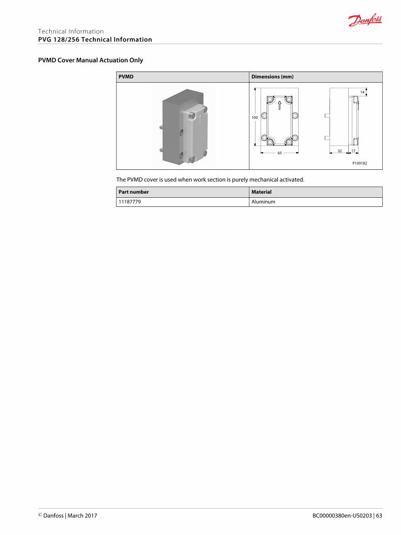
PVMD Dimensions (mm)
100
65 32 17
14
P109182
The PVMD cover is used when work section is purely mechanical activated.
Part number Material
11187779 Aluminum
Technical InformationPVG 128/256 Technical Information
PVMD Cover Manual Actuation Only
© Danfoss | March 2017 BC00000380en-US0203 | 63
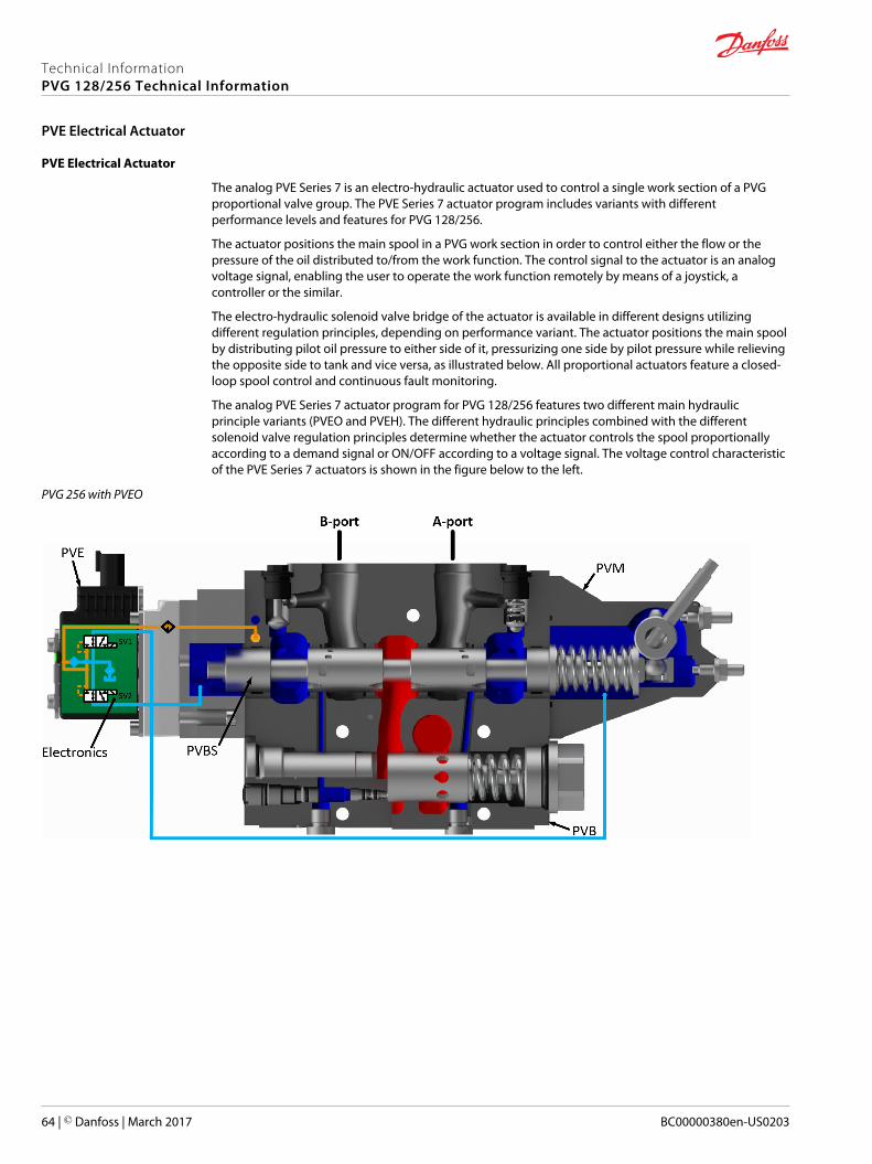
PVE Electrical Actuator
The analog PVE Series 7 is an electro-hydraulic actuator used to control a single work section of a PVGproportional valve group. The PVE Series 7 actuator program includes variants with differentperformance levels and features for PVG 128/256.
The actuator positions the main spool in a PVG work section in order to control either the flow or thepressure of the oil distributed to/from the work function. The control signal to the actuator is an analogvoltage signal, enabling the user to operate the work function remotely by means of a joystick, acontroller or the similar.
The electro-hydraulic solenoid valve bridge of the actuator is available in different designs utilizingdifferent regulation principles, depending on performance variant. The actuator positions the main spoolby distributing pilot oil pressure to either side of it, pressurizing one side by pilot pressure while relievingthe opposite side to tank and vice versa, as illustrated below. All proportional actuators feature a closed-loop spool control and continuous fault monitoring.
The analog PVE Series 7 actuator program for PVG 128/256 features two different main hydraulicprinciple variants (PVEO and PVEH). The different hydraulic principles combined with the differentsolenoid valve regulation principles determine whether the actuator controls the spool proportionallyaccording to a demand signal or ON/OFF according to a voltage signal. The voltage control characteristicof the PVE Series 7 actuators is shown in the figure below to the left.
PVG 256 with PVEO
Technical InformationPVG 128/256 Technical Information
PVE Electrical Actuator
64 | © Danfoss | March 2017 BC00000380en-US0203
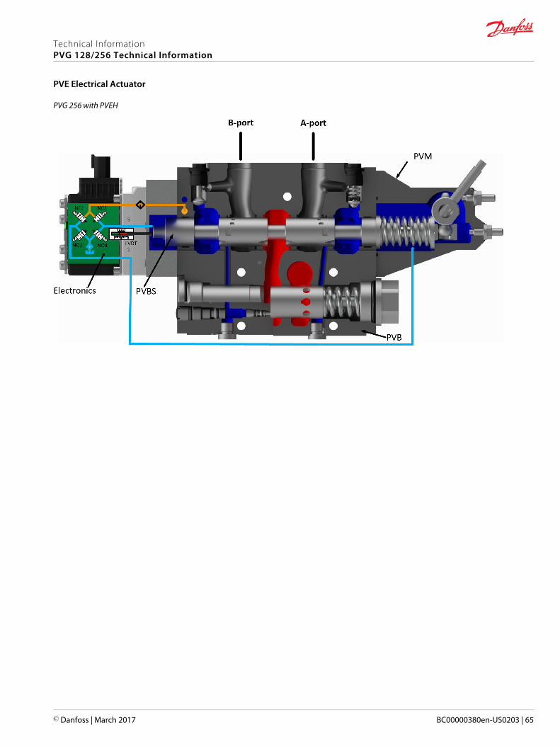
PVG 256 with PVEH
Technical InformationPVG 128/256 Technical Information
PVE Electrical Actuator
© Danfoss | March 2017 BC00000380en-US0203 | 65
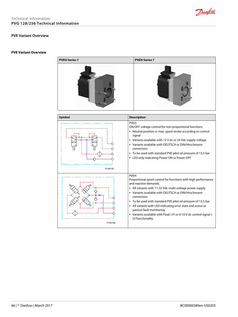
PVE Variant Overview
PVEO Series 7 PVEH Series 7
Symbol Description
P109195
PVEOON/OFF voltage control for non-proportional functions.• Neutral position or max. spool stroke according to control
signal• Variants available with 12 V dc or 24 Vdc supply voltage• Variants available with DEUTSCH or DIN/Hirschmann
connectors• To be used with standard PVE pilot oil pressure of 13.5 bar• LED only indicating Power ON or Power OFF
P109198
PVEHProportional spool control for functions with high performanceand reaction demands.• All variants with 11-32 Vdc multi-voltage power supply• Variants available with DEUTSCH or DIN/Hirschmann
connectors• To be used with standard PVE pilot oil pressure of 13.5 bar• All variants with LED indicating error state and active or
passive fault monitoring• Variants available with Float (-F) or 0-10 V dc control signal (-
U) functionality
Technical InformationPVG 128/256 Technical Information
PVE Variant Overview
66 | © Danfoss | March 2017 BC00000380en-US0203
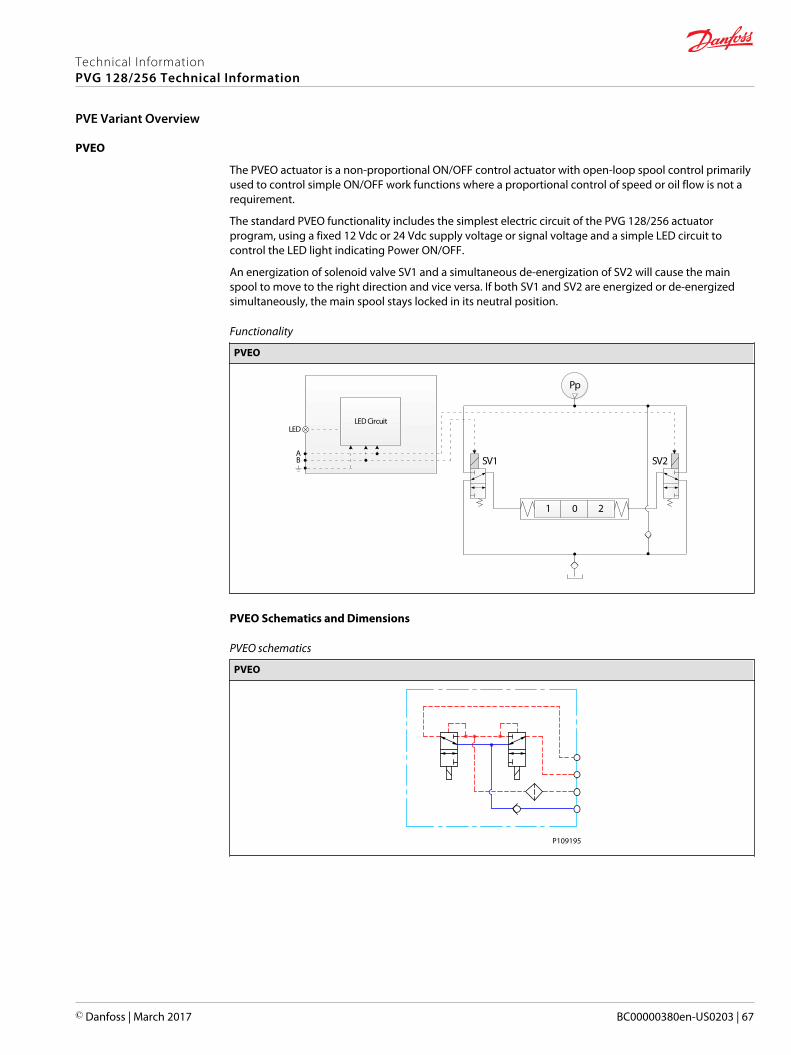
PVEO
The PVEO actuator is a non-proportional ON/OFF control actuator with open-loop spool control primarilyused to control simple ON/OFF work functions where a proportional control of speed or oil flow is not arequirement.
The standard PVEO functionality includes the simplest electric circuit of the PVG 128/256 actuatorprogram, using a fixed 12 Vdc or 24 Vdc supply voltage or signal voltage and a simple LED circuit tocontrol the LED light indicating Power ON/OFF.
An energization of solenoid valve SV1 and a simultaneous de-energization of SV2 will cause the mainspool to move to the right direction and vice versa. If both SV1 and SV2 are energized or de-energizedsimultaneously, the main spool stays locked in its neutral position.
Functionality
PVEO
21 0
Pp
SV2SV1
LED CircuitLED
AB
PVEO Schematics and Dimensions
PVEO schematics
PVEO
P109195
Technical InformationPVG 128/256 Technical Information
PVE Variant Overview
© Danfoss | March 2017 BC00000380en-US0203 | 67
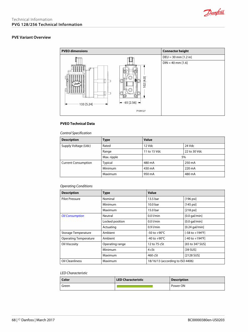
PVEO dimensions Connector height
133 [5.24] 65 [2.56]
102
[4.0
]
P109127
DEU = 30 mm [1.2 in]
DIN = 40 mm [1.6]
PVEO Technical Data
Control Specification
Description Type Value
Supply Voltage (Udc) Rated 12 Vdc 24 Vdc
Range 11 to 15 Vdc 22 to 30 Vdc
Max. ripple 5%
Current Consumption Typical 480 mA 250 mA
Minimum 430 mA 220 mA
Maximum 950 mA 480 mA
Operating Conditions
Description Type Value
Pilot Pressure Nominal 13.5 bar [196 psi]
Minimum 10.0 bar [145 psi]
Maximum 15.0 bar [218 psi]
Oil Consumption Neutral 0.0 l/min [0.0 gal/min]
Locked position 0.0 l/min [0.0 gal/min]
Actuating 0.9 l/min [0.24 gal/min]
Storage Temperature Ambient -50 to +90°C [-58 to +194°F]
Operating Temperature Ambient -40 to +90°C [-40 to +194°F]
Oil Viscosity Operating range 12 to 75 cSt [65 to 347 SUS]
Minimum 4 cSt [39 SUS]
Maximum 460 cSt [2128 SUS]
Oil Cleanliness Maximum 18/16/13 (according to ISO 4406)
LED Characteristic
Color LED Characteristic Description
Green Power ON
Technical InformationPVG 128/256 Technical Information
PVE Variant Overview
68 | © Danfoss | March 2017 BC00000380en-US0203
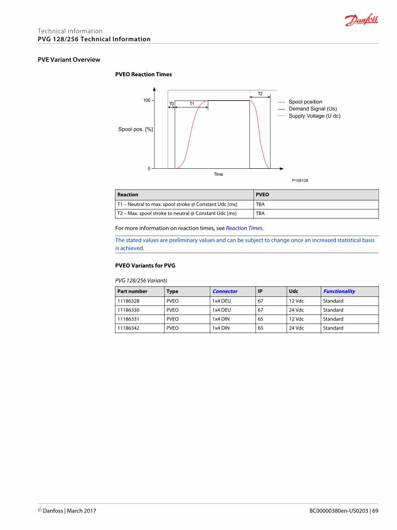
PVEO Reaction Times
100
0Time
T0 T1
T2
P109128
Spool positionDemand Signal (Us)Supply Voltage (U dc)
Spool pos. [%]
Reaction PVEO
T1 – Neutral to max. spool stroke @ Constant Udc [ms] TBA
T2 – Max. spool stroke to neutral @ Constant Udc [ms] TBA
For more information on reaction times, see Reaction Times.
The stated values are preliminary values and can be subject to change once an increased statistical basisis achieved.
PVEO Variants for PVG
PVG 128/256 Variants
Part number Type Connector IP Udc Functionality
11186328 PVEO 1x4 DEU 67 12 Vdc Standard
11186330 PVEO 1x4 DEU 67 24 Vdc Standard
11186331 PVEO 1x4 DIN 65 12 Vdc Standard
11186342 PVEO 1x4 DIN 65 24 Vdc Standard
Technical InformationPVG 128/256 Technical Information
PVE Variant Overview
© Danfoss | March 2017 BC00000380en-US0203 | 69
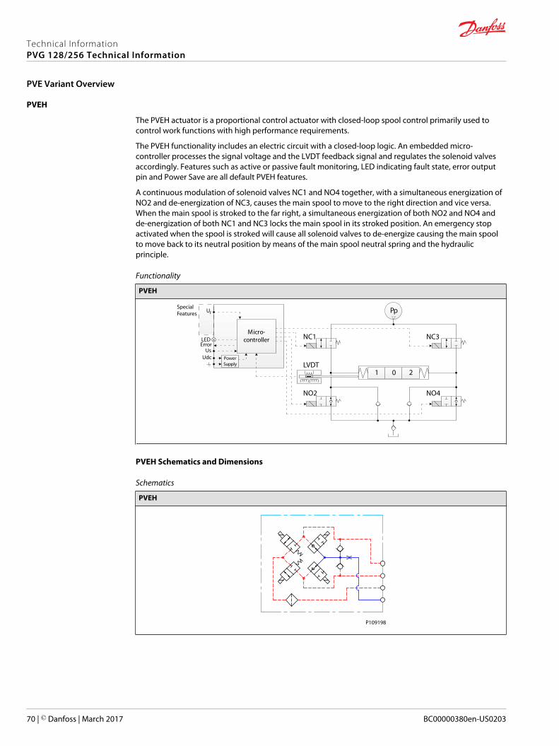
PVEH
The PVEH actuator is a proportional control actuator with closed-loop spool control primarily used tocontrol work functions with high performance requirements.
The PVEH functionality includes an electric circuit with a closed-loop logic. An embedded micro-controller processes the signal voltage and the LVDT feedback signal and regulates the solenoid valvesaccordingly. Features such as active or passive fault monitoring, LED indicating fault state, error outputpin and Power Save are all default PVEH features.
A continuous modulation of solenoid valves NC1 and NO4 together, with a simultaneous energization ofNO2 and de-energization of NC3, causes the main spool to move to the right direction and vice versa.When the main spool is stroked to the far right, a simultaneous energization of both NO2 and NO4 andde-energization of both NC1 and NC3 locks the main spool in its stroked position. An emergency stopactivated when the spool is stroked will cause all solenoid valves to de-energize causing the main spoolto move back to its neutral position by means of the main spool neutral spring and the hydraulicprinciple.
Functionality
PVEH
21 0
Pp
Micro-controller
PowerSupply
F
LEDError
U
UsUdc
NC1 NC3
LVDT
NO2 NO4
SpecialFeatures
PVEH Schematics and Dimensions
Schematics
PVEH
P109198
Technical InformationPVG 128/256 Technical Information
PVE Variant Overview
70 | © Danfoss | March 2017 BC00000380en-US0203
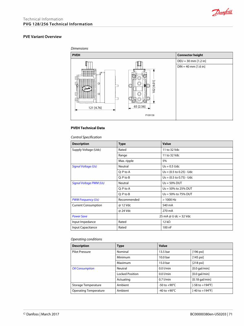
Dimensions
PVEH Connector height
102
[4.0
1]
65 [2.56]121 [4.76]
P109158
DEU = 30 mm [1.2 in]
DIN = 40 mm [1.6 in]
PVEH Technical Data
Control Specification
Description Type Value
Supply Voltage (Udc) Rated 11 to 32 Vdc
Range 11 to 32 Vdc
Max. ripple 5%
Signal Voltage (Us) Neutral Us = 0.5 Udc
Q: P to A Us = (0.5 to 0.25) ∙ Udc
Q: P to B Us = (0.5 to 0.75) ∙ Udc
Signal Voltage PWM (Us) Neutral Us = 50% DUT
Q: P to A Us = 50% to 25% DUT
Q: P to B Us = 50% to 75% DUT
PWM Frequency (Us) Recommended > 1000 Hz
Current Consumption @ 12 Vdc 540 mA
@ 24 Vdc 270 mA
Power Save 25 mA @ U dc = 32 Vdc
Input Impedance Rated 12 kΩ
Input Capacitance Rated 100 nF
Operating conditions
Description Type Value
Pilot Pressure Nominal 13.5 bar [196 psi]
Minimum 10.0 bar [145 psi]
Maximum 15.0 bar [218 psi]
Oil Consumption Neutral 0.0 l/min [0.0 gal/min]
Locked Position 0.0 l/min [0.0 gal/min]
Actuating 0.7 l/min [0.18 gal/min]
Storage Temperature Ambient -50 to +90°C [-58 to +194°F]
Operating Temperature Ambient -40 to +90°C [-40 to +194°F]
Technical InformationPVG 128/256 Technical Information
PVE Variant Overview
© Danfoss | March 2017 BC00000380en-US0203 | 71
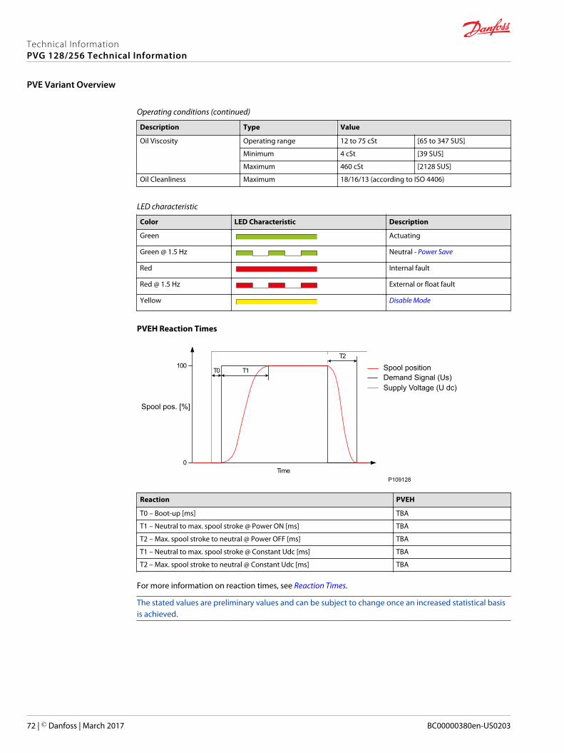
Operating conditions (continued)
Description Type Value
Oil Viscosity Operating range 12 to 75 cSt [65 to 347 SUS]
Minimum 4 cSt [39 SUS]
Maximum 460 cSt [2128 SUS]
Oil Cleanliness Maximum 18/16/13 (according to ISO 4406)
LED characteristic
Color LED Characteristic Description
Green Actuating
Green @ 1.5 Hz Neutral - Power Save
Red Internal fault
Red @ 1.5 Hz External or float fault
Yellow Disable Mode
PVEH Reaction Times
100
0Time
T0 T1
T2
P109128
Spool positionDemand Signal (Us)Supply Voltage (U dc)
Spool pos. [%]
Reaction PVEH
T0 – Boot-up [ms] TBA
T1 – Neutral to max. spool stroke @ Power ON [ms] TBA
T2 – Max. spool stroke to neutral @ Power OFF [ms] TBA
T1 – Neutral to max. spool stroke @ Constant Udc [ms] TBA
T2 – Max. spool stroke to neutral @ Constant Udc [ms] TBA
For more information on reaction times, see Reaction Times.
The stated values are preliminary values and can be subject to change once an increased statistical basisis achieved.
Technical InformationPVG 128/256 Technical Information
PVE Variant Overview
72 | © Danfoss | March 2017 BC00000380en-US0203
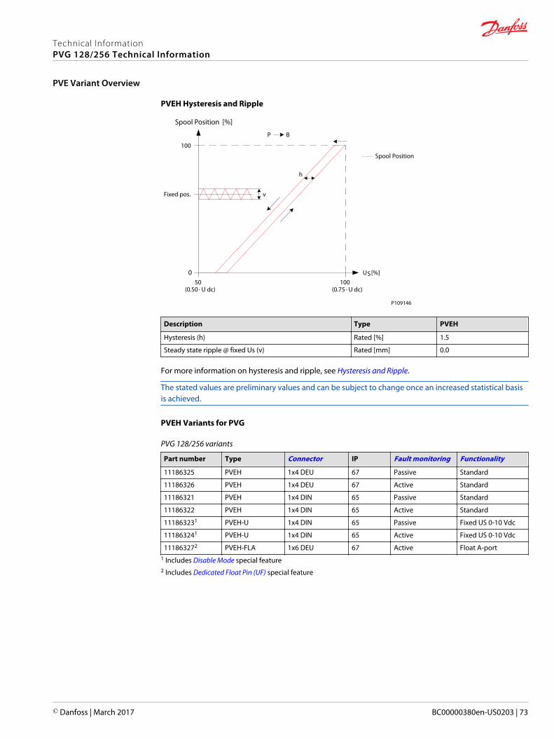
PVEH Hysteresis and Ripple
US [%]
100
0
Spool Position [%]
100(0.75 ∙ U dc)
BP
h
50(0.50 ∙ U dc)
vFixed pos.
Spool Position
P109146
Description Type PVEH
Hysteresis (h) Rated [%] 1.5
Steady state ripple @ fixed Us (v) Rated [mm] 0.0
For more information on hysteresis and ripple, see Hysteresis and Ripple.
The stated values are preliminary values and can be subject to change once an increased statistical basisis achieved.
PVEH Variants for PVG
PVG 128/256 variants
Part number Type Connector IP Fault monitoring Functionality
11186325 PVEH 1x4 DEU 67 Passive Standard
11186326 PVEH 1x4 DEU 67 Active Standard
11186321 PVEH 1x4 DIN 65 Passive Standard
11186322 PVEH 1x4 DIN 65 Active Standard
111863231 PVEH-U 1x4 DIN 65 Passive Fixed US 0-10 Vdc
111863241 PVEH-U 1x4 DIN 65 Active Fixed US 0-10 Vdc
111863272 PVEH-FLA 1x6 DEU 67 Active Float A-port1 Includes Disable Mode special feature2 Includes Dedicated Float Pin (UF) special feature
Technical InformationPVG 128/256 Technical Information
PVE Variant Overview
© Danfoss | March 2017 BC00000380en-US0203 | 73
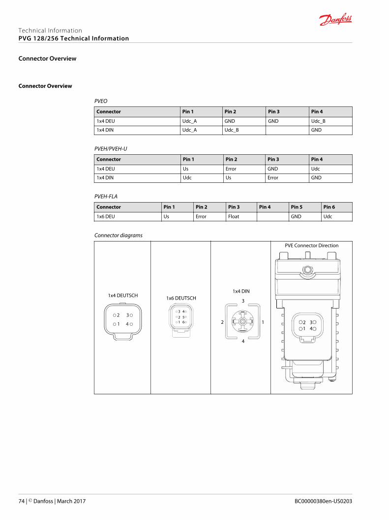
Connector Overview
PVEO
Connector Pin 1 Pin 2 Pin 3 Pin 4
1x4 DEU Udc_A GND GND Udc_B
1x4 DIN Udc_A Udc_B GND
PVEH/PVEH-U
Connector Pin 1 Pin 2 Pin 3 Pin 4
1x4 DEU Us Error GND Udc
1x4 DIN Udc Us Error GND
PVEH-FLA
Connector Pin 1 Pin 2 Pin 3 Pin 4 Pin 5 Pin 6
1x6 DEU Us Error Float GND Udc
Connector diagrams
1x4 DEUTSCH
2 3
41
1x6 DEUTSCH
123 4
56
1x4 DIN
1 2
3
4
PVE Connector Direction
1
2 3
412 3
4
Technical InformationPVG 128/256 Technical Information
Connector Overview
74 | © Danfoss | March 2017 BC00000380en-US0203
All proportional control PVG 128/256 actuators feature an integrated fault monitoring, detecting spoolstroke inconsistencies, internal hardware defects and demand signal inconsistencies.
The actuators feature a generic fault reaction and specific fault reactions depending on the type of faultmonitoring, either passive or active. Passive and active fault monitoring refers to whether or not theactuator is reacting on the error when it is detected.
Active
With an active fault monitoring, no matter what kind of error is detected, the solenoid valves will bedisabled and the operation that the valves/spool controls will stop immediately. Active fault monitoringkeeps a “memory” of the error, even if it is no longer registered. The active fault monitoring does not haveAuto Recovery because of this “memory” and a reboot/restart will therefore be required to reactivate thesolenoid valves.
With an active fault monitoring the following scenarios will take place when an error is detected/occurs:• The LED light will switch from green to red and the error pin output will go high• The solenoid valves will be disabled and the operation that the valves/spool controls will stop
immediately• The active fault monitoring does not have Auto Recovery, so when the error is fixed/no longer is
registered a reboot/restart of the PVE is required to reactivate it.
Passive
Passive fault monitoring does not disable the solenoid valves when an error is detected. It will continueto operate despite that an error was detected. When the error no longer is registered the passive faultmonitoring will “forget” the error and continue as if the error was never there.
With a passive fault monitoring the following conditions will happen when an error is detected/occurs:• The LED light will switch from green to red and the error pin output will go high• The solenoid valves will continue operating at the set point given at the time of the error
‒ Only exception is if the error is caused by the supply voltage (Udc) being either above or belowthe allowed range or if the temperature measured on the internal electronics board is higher thanallowed. In these cases, the solenoid valves will be disabled.
An overview of the error states and the reaction to the errors can be seen in the table Fault ReactionOverview on page 76.
Generic Fault Reaction
All PVE’s with fault monitoring are triggered by the following four main events:
Control Signal Monitoring The Control signal voltage (Us) is continuously monitored. The permissible range is between 15% and85% of the supply voltage (U dc). Outside this range the PVE will switch into an error state. Adisconnected Us pin (floating) is recognized as a neutral set point.
Transducer/LVDT Supervision The internal LVDT wires are monitored. If the signals are interrupted or short-circuited, the PVE willswitch into an error state.
Supervision of Spool Position The actual position must always correspond to the demanded position (Us). If the actual spool position isfurther out from neutral than the demanded spool position or in opposite direction, the PVE will switchinto an error state. Spool position closer to neutral and in same direction will not cause an error state –the situation is considered “in control.”
Float Position Monitoring Float position must be entered or left within a time limit. On the 1x6 pin float PVE’s a too high delay willcause an error state – this is only relevant for the 1x6 pin PVEH-F actuators.
Temperature Monitoring When the temperature is too high the PVE's LED will light constant red and solenoid valves will bedisabled.
Technical InformationPVG 128/256 Technical Information
Fault Monitoring and Fault Reaction
© Danfoss | March 2017 BC00000380en-US0203 | 75
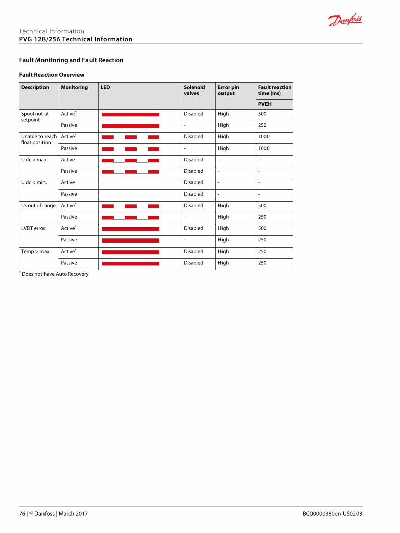
Fault Reaction Overview
Description Monitoring LED Solenoidvalves
Error pinoutput
Fault reactiontime (ms)
PVEH
Spool not atsetpoint
Active* Disabled High 500
Passive - High 250
Unable to reachfloat position
Active* Disabled High 1000
Passive - High 1000
U dc > max. Active Disabled - -
Passive Disabled - -
U dc < min. Active Disabled - -
Passive Disabled - -
Us out of range Active* Disabled High 500
Passive - High 250
LVDT error Active* Disabled High 500
Passive - High 250
Temp > max. Active* Disabled High 250
Passive Disabled High 250
* Does not have Auto Recovery
Technical InformationPVG 128/256 Technical Information
Fault Monitoring and Fault Reaction
76 | © Danfoss | March 2017 BC00000380en-US0203
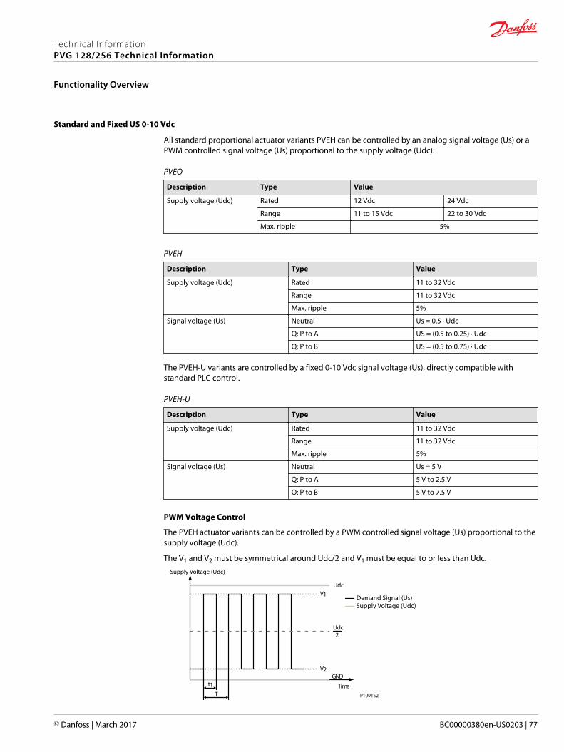
Standard and Fixed US 0-10 Vdc
All standard proportional actuator variants PVEH can be controlled by an analog signal voltage (Us) or aPWM controlled signal voltage (Us) proportional to the supply voltage (Udc).
PVEO
Description Type Value
Supply voltage (Udc) Rated 12 Vdc 24 Vdc
Range 11 to 15 Vdc 22 to 30 Vdc
Max. ripple 5%
PVEH
Description Type Value
Supply voltage (Udc) Rated 11 to 32 Vdc
Range 11 to 32 Vdc
Max. ripple 5%
Signal voltage (Us) Neutral Us = 0.5 ∙ Udc
Q: P to A US = (0.5 to 0.25) ∙ Udc
Q: P to B US = (0.5 to 0.75) ∙ Udc
The PVEH-U variants are controlled by a fixed 0-10 Vdc signal voltage (Us), directly compatible withstandard PLC control.
PVEH-U
Description Type Value
Supply voltage (Udc) Rated 11 to 32 Vdc
Range 11 to 32 Vdc
Max. ripple 5%
Signal voltage (Us) Neutral Us = 5 V
Q: P to A 5 V to 2.5 V
Q: P to B 5 V to 7.5 V
PWM Voltage Control
The PVEH actuator variants can be controlled by a PWM controlled signal voltage (Us) proportional to thesupply voltage (Udc).
The V1 and V2 must be symmetrical around Udc/2 and V1 must be equal to or less than Udc.
Time
Udc
Udc2
GND
V1
V2
t1T P109152
Demand Signal (Us)Supply Voltage (Udc)
Supply Voltage (Udc)
Technical InformationPVG 128/256 Technical Information
Functionality Overview
© Danfoss | March 2017 BC00000380en-US0203 | 77
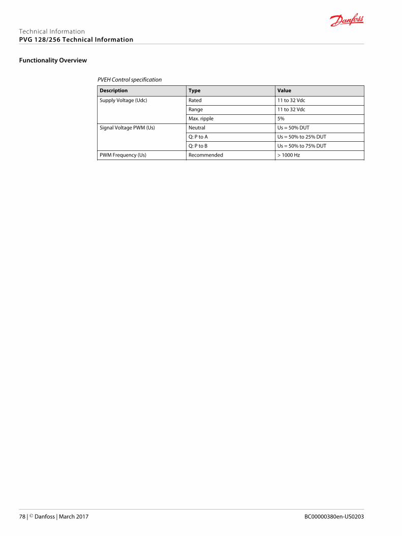
PVEH Control specification
Description Type Value
Supply Voltage (Udc) Rated 11 to 32 Vdc
Range 11 to 32 Vdc
Max. ripple 5%
Signal Voltage PWM (Us) Neutral Us = 50% DUT
Q: P to A Us = 50% to 25% DUT
Q: P to B Us = 50% to 75% DUT
PWM Frequency (Us) Recommended > 1000 Hz
Technical InformationPVG 128/256 Technical Information
Functionality Overview
78 | © Danfoss | March 2017 BC00000380en-US0203
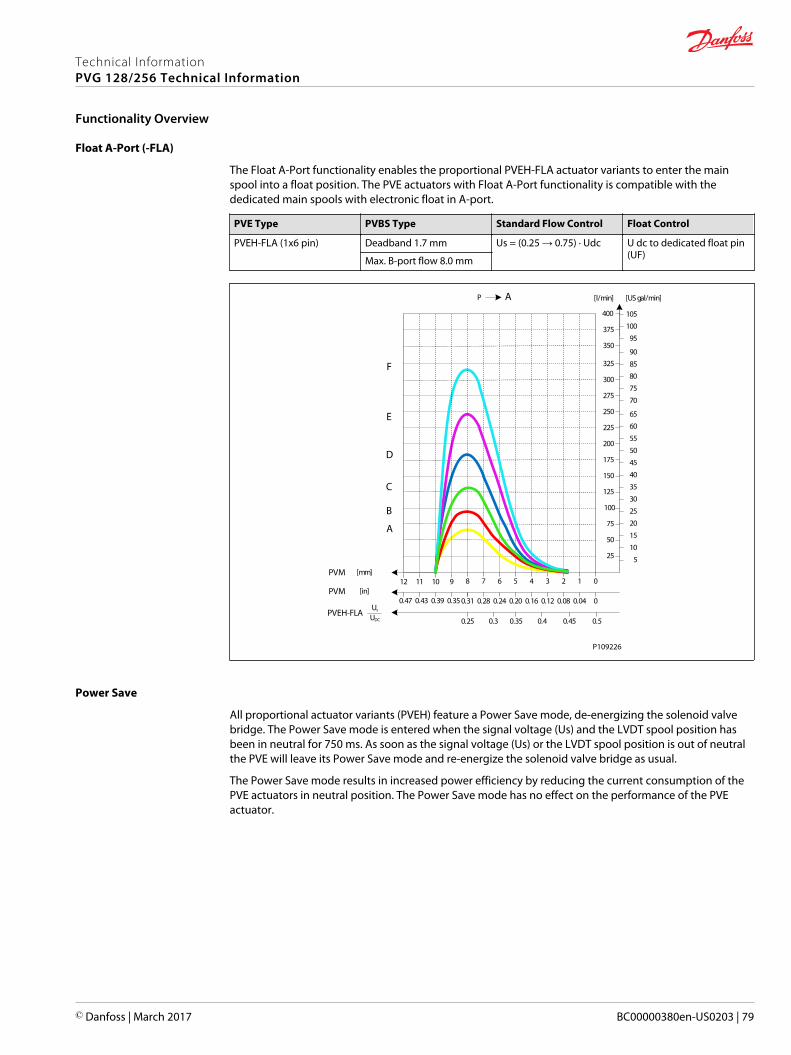
Float A-Port (-FLA)
The Float A-Port functionality enables the proportional PVEH-FLA actuator variants to enter the mainspool into a float position. The PVE actuators with Float A-Port functionality is compatible with thededicated main spools with electronic float in A-port.
PVE Type PVBS Type Standard Flow Control Float Control
PVEH-FLA (1x6 pin) Deadband 1.7 mm Us = (0.25 → 0.75) ∙ Udc U dc to dedicated float pin(UF)Max. B-port flow 8.0 mm
AP
25
50
75
100
125
150
175
200
225
250
275
300
325
[l/min] [US gal/min]
[mm]PVM01234567
[in]PVM00.040.080.120.160.200.240.28
PVEH-FLAUs
UDC 0.50.450.40.350.3
8
0.31
9101112
350
375
400
0.350.390.430.47
5
10
15
20
25
30
35
40
45
50
55
60
65
70
75
80
85
90
95
100
105
A
B
C
D
E
F
0.25
P109226
Power Save
All proportional actuator variants (PVEH) feature a Power Save mode, de-energizing the solenoid valvebridge. The Power Save mode is entered when the signal voltage (Us) and the LVDT spool position hasbeen in neutral for 750 ms. As soon as the signal voltage (Us) or the LVDT spool position is out of neutralthe PVE will leave its Power Save mode and re-energize the solenoid valve bridge as usual.
The Power Save mode results in increased power efficiency by reducing the current consumption of thePVE actuators in neutral position. The Power Save mode has no effect on the performance of the PVEactuator.
Technical InformationPVG 128/256 Technical Information
Functionality Overview
© Danfoss | March 2017 BC00000380en-US0203 | 79
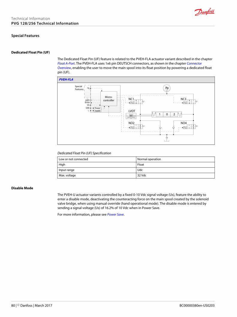
Dedicated Float Pin (UF)
The Dedicated Float Pin (UF) feature is related to the PVEH-FLA actuator variant described in the chapter Float A-Port. The PVEH-FLA uses 1x6 pin DEUTSCH connectors, as shown in the chapter ConnectorOverview, enabling the user to move the main spool into its float position by powering a dedicated floatpin (UF).
PVEH-FLA
21 0
Pp
Micro-controller
PowerSupply
F
LEDError
U
UsUdc
NC1 NC3
LVDT
NO2 NO4
SpecialFeatures
Dedicated Float Pin (UF) Specification
Low or not connected Normal operation
High Float
Input range Udc
Max. voltage 32 Vdc
Disable Mode
The PVEH-U actuator variants controlled by a fixed 0-10 Vdc signal voltage (Us), feature the ability toenter a disable mode, deactivating the counteracting force on the main spool created by the solenoidvalve bridge, when using manual override (hand operational mode). The disable mode is entered bysending a signal voltage (Us) of 16.2% of 10 Vdc when in Power Save.
For more information, please see Power Save.
Technical InformationPVG 128/256 Technical Information
Special Features
80 | © Danfoss | March 2017 BC00000380en-US0203
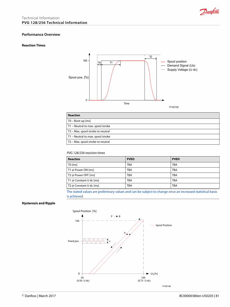
Reaction Times
100
0Time
T0 T1
T2
P109128
Spool positionDemand Signal (Us)Supply Voltage (U dc)
Spool pos. [%]
Reaction
T0 – Boot-up [ms]
T1 – Neutral to max. spool stroke
T2 – Max. spool stroke to neutral
T1 – Neutral to max. spool stroke
T2 – Max. spool stroke to neutral
PVG 128/256 reaction times
Reaction PVEO PVEH
T0 [ms] TBA TBA
T1 @ Power ON [ms] TBA TBA
T2 @ Power OFF [ms] TBA TBA
T1 @ Constant U dc [ms] TBA TBA
T2 @ Constant U dc [ms] TBA TBA
The stated values are preliminary values and can be subject to change once an increased statistical basisis achieved.
Hysteresis and Ripple
US [%]
100
0
Spool Position [%]
100(0.75 ∙ U dc)
BP
h
50(0.50 ∙ U dc)
vFixed pos.
Spool Position
P109146
Technical InformationPVG 128/256 Technical Information
Performance Overview
© Danfoss | March 2017 BC00000380en-US0203 | 81
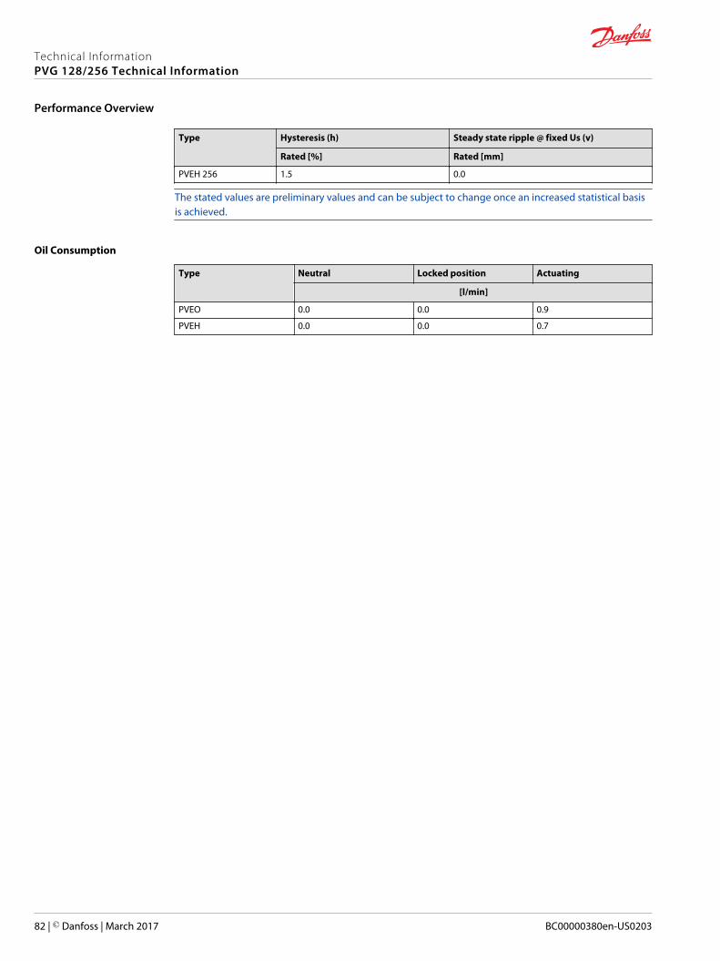
Type Hysteresis (h) Steady state ripple @ fixed Us (v)
Rated [%] Rated [mm]
PVEH 256 1.5 0.0
The stated values are preliminary values and can be subject to change once an increased statistical basisis achieved.
Oil Consumption
Type Neutral Locked position Actuating
[l/min]
PVEO 0.0 0.0 0.9
PVEH 0.0 0.0 0.7
Technical InformationPVG 128/256 Technical Information
Performance Overview
82 | © Danfoss | March 2017 BC00000380en-US0203
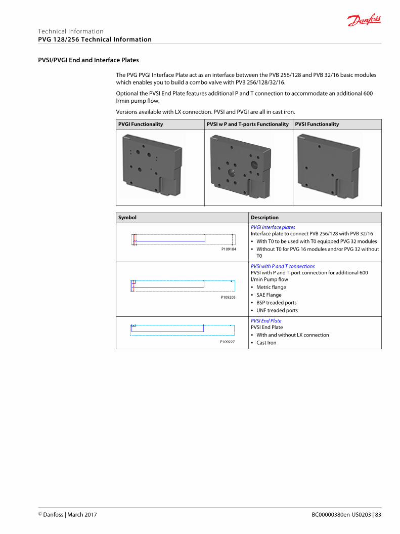
The PVG PVGI Interface Plate act as an interface between the PVB 256/128 and PVB 32/16 basic moduleswhich enables you to build a combo valve with PVB 256/128/32/16.
Optional the PVSI End Plate features additional P and T connection to accommodate an additional 600l/min pump flow.
Versions available with LX connection. PVSI and PVGI are all in cast iron.
PVGI Functionality PVSI w P and T-ports Functionality PVSI Functionality
Symbol Description
P109184
PVGI interface platesInterface plate to connect PVB 256/128 with PVB 32/16• With T0 to be used with T0 equipped PVG 32 modules• Without T0 for PVG 16 modules and/or PVG 32 without
T0
P109205
PVSI with P and T connectionsPVSI with P and T-port connection for additional 600l/min Pump flow• Metric flange• SAE Flange• BSP treaded ports• UNF treaded ports
P109227
PVSI End PlatePVSI End Plate• With and without LX connection• Cast Iron
Technical InformationPVG 128/256 Technical Information
PVSI/PVGI End and Interface Plates
© Danfoss | March 2017 BC00000380en-US0203 | 83
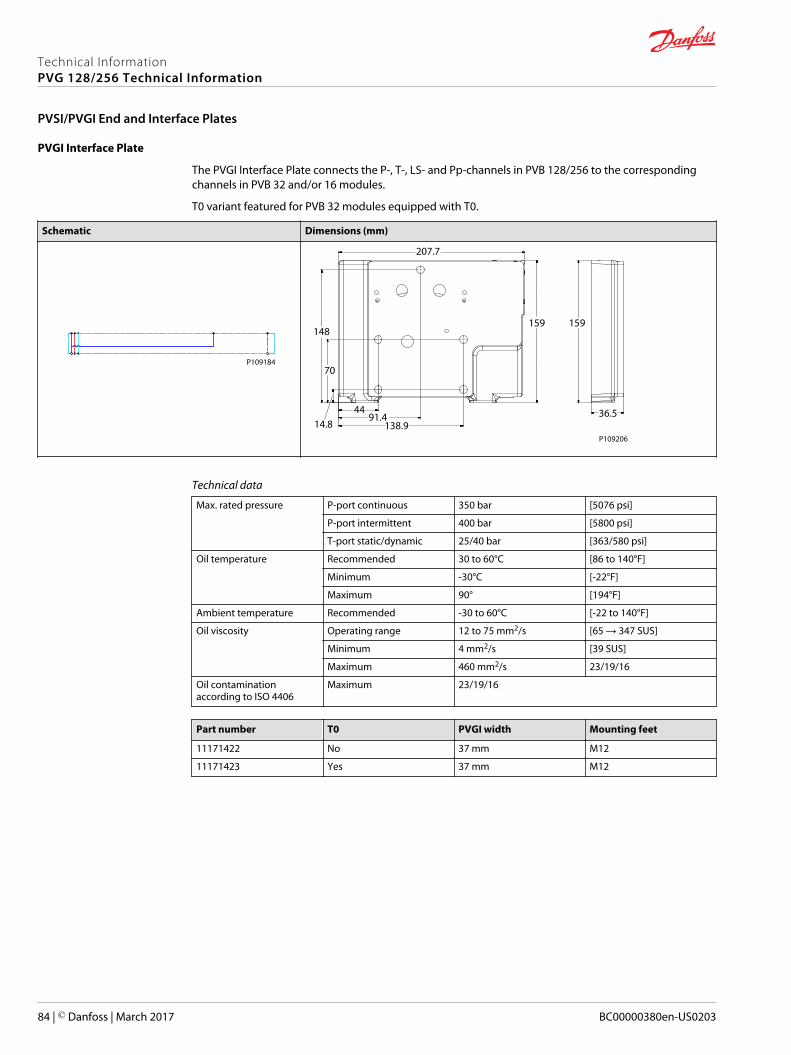
PVGI Interface Plate
The PVGI Interface Plate connects the P-, T-, LS- and Pp-channels in PVB 128/256 to the correspondingchannels in PVB 32 and/or 16 modules.
T0 variant featured for PVB 32 modules equipped with T0.
Schematic Dimensions (mm)
P109184
138.991.4
4414.8
70
148
207.7
159 159
36.5
P109206
Technical data
Max. rated pressure P-port continuous 350 bar [5076 psi]
P-port intermittent 400 bar [5800 psi]
T-port static/dynamic 25/40 bar [363/580 psi]
Oil temperature Recommended 30 to 60°C [86 to 140°F]
Minimum -30°C [-22°F]
Maximum 90° [194°F]
Ambient temperature Recommended -30 to 60°C [-22 to 140°F]
Oil viscosity Operating range 12 to 75 mm2/s [65 → 347 SUS]
Minimum 4 mm2/s [39 SUS]
Maximum 460 mm2/s 23/19/16
Oil contaminationaccording to ISO 4406
Maximum 23/19/16
Part number T0 PVGI width Mounting feet
11171422 No 37 mm M12
11171423 Yes 37 mm M12
Technical InformationPVG 128/256 Technical Information
PVSI/PVGI End and Interface Plates
84 | © Danfoss | March 2017 BC00000380en-US0203
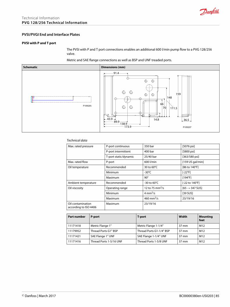
PVSI with P and T port
The PVSI with P and T port connections enables an additional 600 l/min pump flow to a PVG 128/256valve.
Metric and SAE flange connections as well as BSP and UNF treaded ports.
Schematic Dimensions (mm)
P109205
173.9138.9
89.943.9
91.4
159148
111.57066
14.8 36.5
P109207
Technical data
Max. rated pressure P-port continuous 350 bar [5076 psi]
P-port intermittent 400 bar [5800 psi]
T-port static/dynamic 25/40 bar [363/580 psi]
Max. rated flow P-port 600 l/min [159 US gal/min]
Oil temperature Recommended 30 to 60°C [86 to 140°F]
Minimum -30°C [-22°F]
Maximum 90° [194°F]
Ambient temperature Recommended -30 to 60°C [-22 to 140°F]
Oil viscosity Operating range 12 to 75 mm2/s [65 → 347 SUS]
Minimum 4 mm2/s [39 SUS]
Maximum 460 mm2/s 23/19/16
Oil contaminationaccording to ISO 4406
Maximum 23/19/16
Part number P-port T-port Width Mountingfeet
11171418 Metric Flange 1” Metric Flange 1-1/4” 37 mm M12
11179952 Thread Ports G1" BSP Thread Ports G1-1/4" BSP 37 mm M12
11171421 SAE Flange 1” UNF SAE Flange 1-1/4” UNF 37 mm M12
11171416 Thread Ports 1-5/16 UNF Thread Ports 1-5/8 UNF 37 mm M12
Technical InformationPVG 128/256 Technical Information
PVSI/PVGI End and Interface Plates
© Danfoss | March 2017 BC00000380en-US0203 | 85
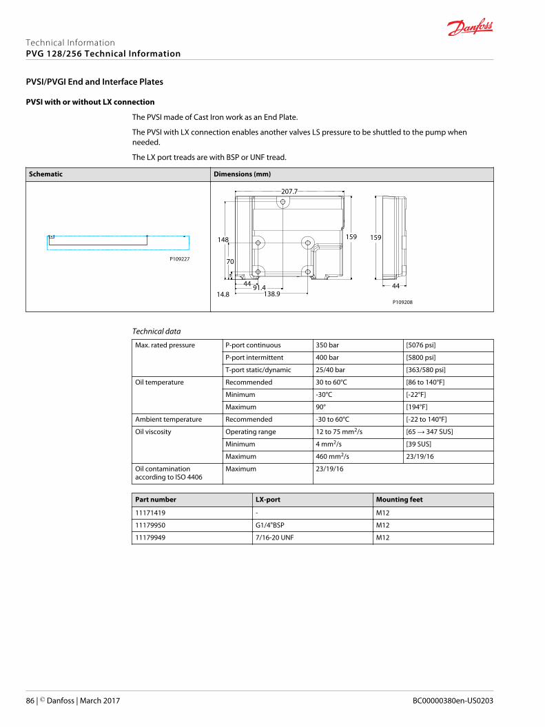
PVSI with or without LX connection
The PVSI made of Cast Iron work as an End Plate.
The PVSI with LX connection enables another valves LS pressure to be shuttled to the pump whenneeded.
The LX port treads are with BSP or UNF tread.
Schematic Dimensions (mm)
P109227
138.991.444
14.8
70
148
207.7
159 159
44
P109208
Technical data
Max. rated pressure P-port continuous 350 bar [5076 psi]
P-port intermittent 400 bar [5800 psi]
T-port static/dynamic 25/40 bar [363/580 psi]
Oil temperature Recommended 30 to 60°C [86 to 140°F]
Minimum -30°C [-22°F]
Maximum 90° [194°F]
Ambient temperature Recommended -30 to 60°C [-22 to 140°F]
Oil viscosity Operating range 12 to 75 mm2/s [65 → 347 SUS]
Minimum 4 mm2/s [39 SUS]
Maximum 460 mm2/s 23/19/16
Oil contaminationaccording to ISO 4406
Maximum 23/19/16
Part number LX-port Mounting feet
11171419 - M12
11179950 G1/4"BSP M12
11179949 7/16-20 UNF M12
Technical InformationPVG 128/256 Technical Information
PVSI/PVGI End and Interface Plates
86 | © Danfoss | March 2017 BC00000380en-US0203
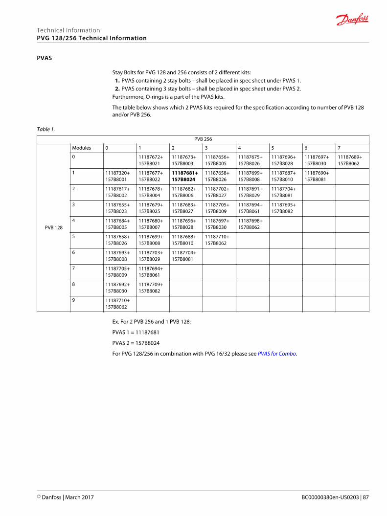
Stay Bolts for PVG 128 and 256 consists of 2 different kits:1. PVAS containing 2 stay bolts – shall be placed in spec sheet under PVAS 1.2. PVAS containing 3 stay bolts – shall be placed in spec sheet under PVAS 2.
Furthermore, O-rings is a part of the PVAS kits.
The table below shows which 2 PVAS kits required for the specification according to number of PVB 128and/or PVB 256.
Table 1.
PVB 256
PVB 128
Modules 0 1 2 3 4 5 6 7
0 11187672+157B8021
11187673+157B8003
11187656+157B8005
11187675+157B8026
11187696+157B8028
11187697+157B8030
11187689+157B8062
1 11187320+157B8001
11187677+157B8022
11187681+157B8024
11187658+157B8026
11187699+157B8008
11187687+157B8010
11187690+157B8081
2 11187617+157B8002
11187678+157B8004
11187682+157B8006
11187702+157B8027
11187691+157B8029
11187704+157B8081
3 11187655+157B8023
11187679+157B8025
11187683+157B8027
11187705+157B8009
11187694+157B8061
11187695+157B8082
4 11187684+157B8005
11187680+157B8007
11187696+157B8028
11187697+157B8030
11187698+157B8062
5 11187658+157B8026
11187699+157B8008
11187688+157B8010
11187710+157B8062
6 11187693+157B8008
11187703+157B8029
11187704+157B8081
7 11187705+157B8009
11187694+157B8061
8 11187692+157B8030
11187709+157B8082
9 11187710+157B8062
Ex. For 2 PVB 256 and 1 PVB 128:
PVAS 1 = 11187681
PVAS 2 = 157B8024
For PVG 128/256 in combination with PVG 16/32 please see PVAS for Combo.
Technical InformationPVG 128/256 Technical Information
PVAS
© Danfoss | March 2017 BC00000380en-US0203 | 87
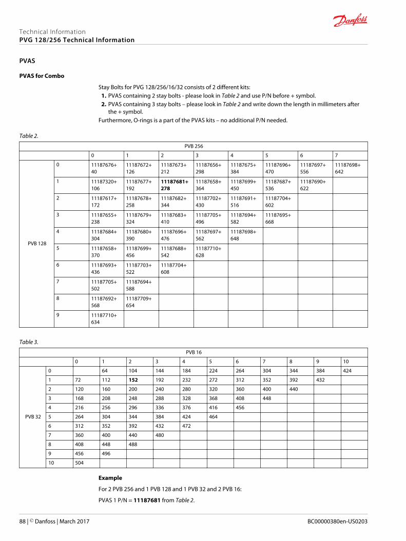
PVAS for Combo
Stay Bolts for PVG 128/256/16/32 consists of 2 different kits:1. PVAS containing 2 stay bolts - please look in Table 2 and use P/N before + symbol.2. PVAS containing 3 stay bolts – please look in Table 2 and write down the length in millimeters after
the + symbol.Furthermore, O-rings is a part of the PVAS kits – no additional P/N needed.
Table 2.
PVB 256
0 1 2 3 4 5 6 7
PVB 128
0 11187676+40
11187672+126
11187673+212
11187656+298
11187675+384
11187696+470
11187697+556
11187698+642
1 11187320+106
11187677+192
11187681+278
11187658+364
11187699+450
11187687+536
11187690+622
2 11187617+172
11187678+258
11187682+344
11187702+430
11187691+516
11187704+602
3 11187655+238
11187679+324
11187683+410
11187705+496
11187694+582
11187695+668
4 11187684+304
11187680+390
11187696+476
11187697+562
11187698+648
5 11187658+370
11187699+456
11187688+542
11187710+628
6 11187693+436
11187703+522
11187704+608
7 11187705+502
11187694+588
8 11187692+568
11187709+654
9 11187710+634
Table 3.
PVB 16
0 1 2 3 4 5 6 7 8 9 10
PVB 32
0 64 104 144 184 224 264 304 344 384 424
1 72 112 152 192 232 272 312 352 392 432
2 120 160 200 240 280 320 360 400 440
3 168 208 248 288 328 368 408 448
4 216 256 296 336 376 416 456
5 264 304 344 384 424 464
6 312 352 392 432 472
7 360 400 440 480
8 408 448 488
9 456 496
10 504
Example
For 2 PVB 256 and 1 PVB 128 and 1 PVB 32 and 2 PVB 16:
PVAS 1 P/N = 11187681 from Table 2.
Technical InformationPVG 128/256 Technical Information
PVAS
88 | © Danfoss | March 2017 BC00000380en-US0203
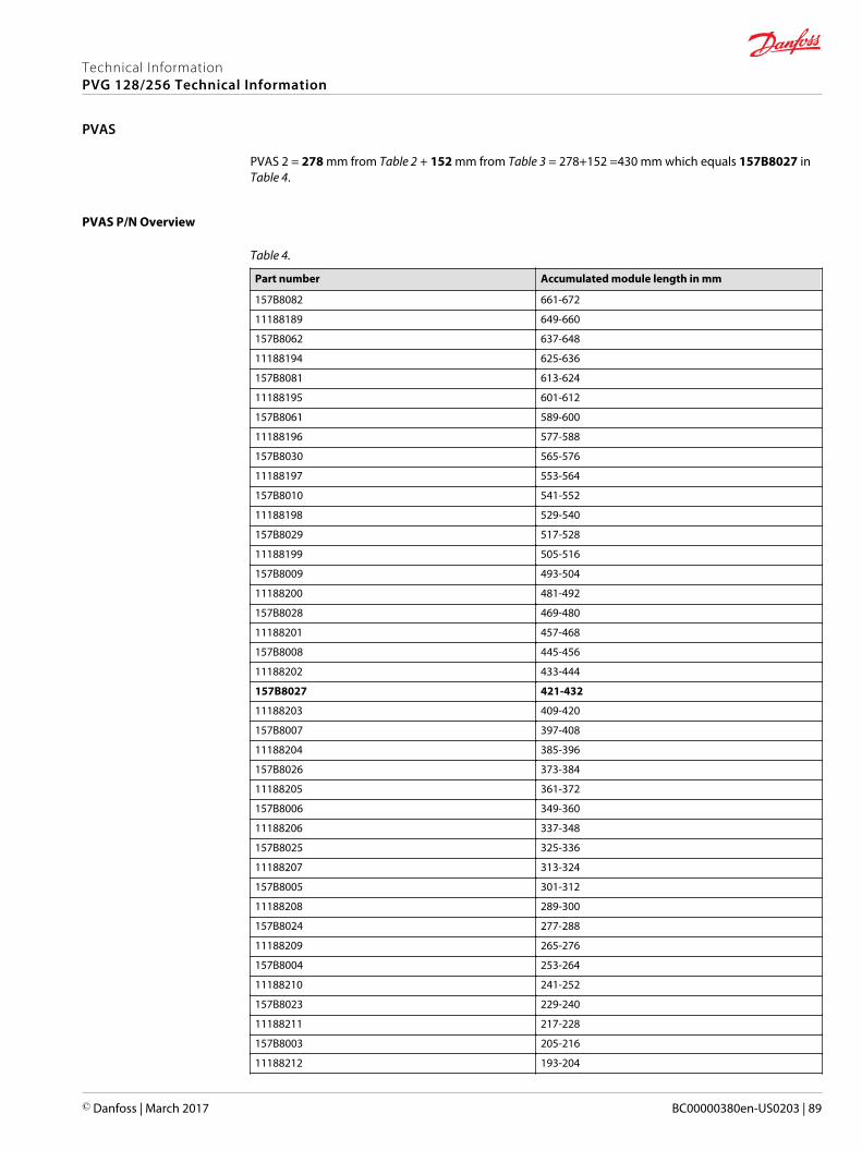
PVAS 2 = 278 mm from Table 2 + 152 mm from Table 3 = 278+152 =430 mm which equals 157B8027 inTable 4.
PVAS P/N Overview
Table 4.
Part number Accumulated module length in mm
157B8082 661-672
11188189 649-660
157B8062 637-648
11188194 625-636
157B8081 613-624
11188195 601-612
157B8061 589-600
11188196 577-588
157B8030 565-576
11188197 553-564
157B8010 541-552
11188198 529-540
157B8029 517-528
11188199 505-516
157B8009 493-504
11188200 481-492
157B8028 469-480
11188201 457-468
157B8008 445-456
11188202 433-444
157B8027 421-432
11188203 409-420
157B8007 397-408
11188204 385-396
157B8026 373-384
11188205 361-372
157B8006 349-360
11188206 337-348
157B8025 325-336
11188207 313-324
157B8005 301-312
11188208 289-300
157B8024 277-288
11188209 265-276
157B8004 253-264
11188210 241-252
157B8023 229-240
11188211 217-228
157B8003 205-216
11188212 193-204
Technical InformationPVG 128/256 Technical Information
PVAS
© Danfoss | March 2017 BC00000380en-US0203 | 89
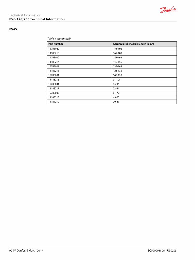
Table 4. (continued)
Part number Accumulated module length in mm
157B8022 181-192
11188213 169-180
157B8002 157-168
11188214 145-156
157B8021 133-144
11188215 121-132
157B8001 109-120
11188216 97-108
157B8031 85-96
11188217 73-84
157B8000 61-72
11188218 49-60
11188219 20-48
Technical InformationPVG 128/256 Technical Information
PVAS
90 | © Danfoss | March 2017 BC00000380en-US0203
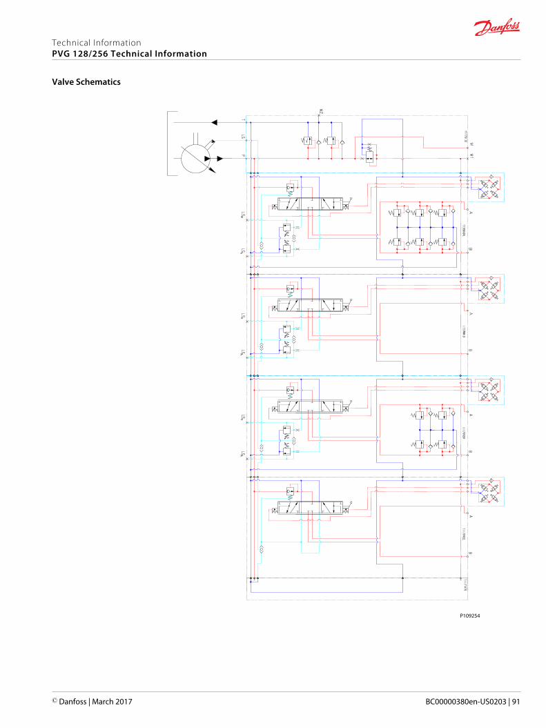
P109254
Technical InformationPVG 128/256 Technical Information
Valve Schematics
© Danfoss | March 2017 BC00000380en-US0203 | 91
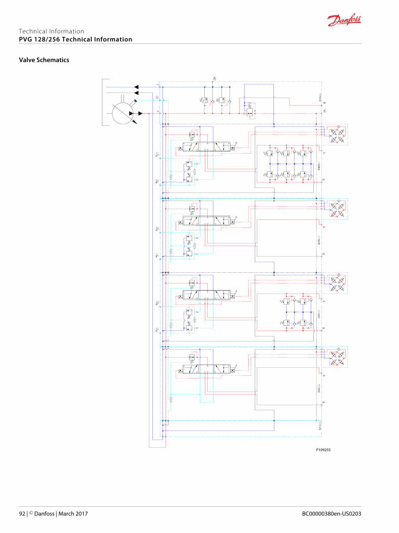
P109255
Technical InformationPVG 128/256 Technical Information
Valve Schematics
92 | © Danfoss | March 2017 BC00000380en-US0203

Technical InformationPVG 128/256 Technical Information
© Danfoss | March 2017 BC00000380en-US0203 | 93
Technical InformationPVG 128/256 Technical Information
94 | © Danfoss | March 2017 BC00000380en-US0203
Technical InformationPVG 128/256 Technical Information
© Danfoss | March 2017 BC00000380en-US0203 | 95
Danfoss Power Solutions is a global manufacturer and supplier of high-quality hydraulic andelectronic components. We specialize in providing state-of-the-art technology and solutionsthat excel in the harsh operating conditions of the mobile off-highway market. Building onour extensive applications expertise, we work closely with our customers to ensureexceptional performance for a broad range of off-highway vehicles.
We help OEMs around the world speed up system development, reduce costs and bringvehicles to market faster.
Danfoss – Your Strongest Partner in Mobile Hydraulics.
Go to www.powersolutions.danfoss.com for further product information.
Wherever off-highway vehicles are at work, so is Danfoss. We offer expert worldwide supportfor our customers, ensuring the best possible solutions for outstanding performance. Andwith an extensive network of Global Service Partners, we also provide comprehensive globalservice for all of our components.
Please contact the Danfoss Power Solution representative nearest you.
Local address:
Danfoss Power Solutions GmbH & Co. OHGKrokamp 35D-24539 Neumünster, GermanyPhone: +49 4321 871 0
Danfoss Power Solutions ApSNordborgvej 81DK-6430 Nordborg, DenmarkPhone: +45 7488 2222
Danfoss Power Solutions (US) Company2800 East 13th StreetAmes, IA 50010, USAPhone: +1 515 239 6000
Danfoss Power Solutions Trading(Shanghai) Co., Ltd.Building #22, No. 1000 Jin Hai RdJin Qiao, Pudong New DistrictShanghai, China 201206Phone: +86 21 3418 5200
Danfoss can accept no responsibility for possible errors in catalogues, brochures and other printed material. Danfoss reserves the right to alter its products without notice. This also applies to productsalready on order provided that such alterations can be made without changes being necessary in specifications already agreed.All trademarks in this material are property of the respective companies. Danfoss and the Danfoss logotype are trademarks of Danfoss A/S. All rights reserved.
© Danfoss | March 2017 BC00000380en-US0203
Products we offer:
• Bent Axis Motors
• Closed Circuit Axial PistonPumps and Motors
• Displays
• Electrohydraulic PowerSteering
• Electrohydraulics
• Hydraulic Power Steering
• Integrated Systems
• Joysticks and ControlHandles
• Microcontrollers andSoftware
• Open Circuit Axial PistonPumps
• Orbital Motors
• PLUS+1® GUIDE
• Proportional Valves
• Sensors
• Steering
• Transit Mixer Drives
Comatrolwww.comatrol.com
Turolla www.turollaocg.com
Hydro-Gearwww.hydro-gear.com
Daikin-Sauer-Danfosswww.daikin-sauer-danfoss.com