Proportional 2-way cartridges - atos-ost.de
10
LIQZO-LEB, LIQZP-LEB LIQZO-LES, LIQZP-LES High Performance 2-way proportional cartridge valves specifically designed for high speed closed loop controls. They are equipped with two LVDT position transducers for best dynamics in not com- pensated flow regulations. The cartridge execution for blocks instal- lation grants high flow capabilities and minimized pressure drops. The integral digital electronic driver performs the valve’s hydraulic regulation according to the reference signal and assures valve-to-valve interchangeability thanks to the factory presetting. High performances valves are available in LEB basic execution with analog refe- rence signals and USB port for software functional parameters setting or in LES full execution which includes also optio- nal fieldbus interfaces for functional parameters setting, reference signals and real-time diagnostics LIQZO: sizes from 16 to 40, Max flow: 600 to 2500 l/min Max pressure: 350 bar LIQZP: sizes from 50 to 100, Max flow: 4000 to 16.000 l/min Max pressure: 420 bar Valve size, see section LIQZO = 16 25 32 40 l/min 250 500 800 1200 LIQZP = 50 63 80 100 l/min 2000 3000 4500 7200 Nominal flow (l/min) at Δp 5 bar 9 0 www.atos.com Proportional 2-way cartridges high performance rugged digital, with two position transducers, ISO 7368 sizes from 16 to 100 Table FS330-0/E 1 MODEL CODE FS330 Integral electronics USB connector Fieldbus connectors Main connector Pilot valve position transducer Air bleeding Air suction port Poppet Sleeve Main stage position transducer Pilot valve X Y B A LIQZO-LEB LIQZO-LES (functional symbol) LIQZO Flow control valve LIQZO = size 16 to 40, Pmax 350 bar LIQZP = size 50 to 100, Pmax 420 bar / / 25 2 L4 * ** * Series number Spool type - regulating characteristics: L4 = linear Configuration: 2 = 2 way - - - - L ES NP SN L = closed-loop two LVDT transducers Alternated P/Q controls - see section SN = none Fieldbus interfaces USB port always present: NP = Not present (1) BP = PROFIBUS DP BC = CANopen EH = EtherCAT Integral digital drivers: EB = basic (1) ES = full LIQZO-LES-SN-BP-322L4 Electronic options, see sections I = current reference input and monitor 4÷20 mA (omit for standard voltage reference input and monitor ±10 V) F = fault signal Q = enable signal Z = double power supply, enable, fault and monitor signals (12 pin connector) (2) 9 Seals material, see sect. , : - = NBR PE = FKM BT = HNBR (1) LEB basic execution available only in version SN-NP (2) Double power supply only for LES LIQZO-LEB LIQZO-LES (simplified symbol)
Transcript of Proportional 2-way cartridges - atos-ost.de

LIQZO-LEB, LIQZP-LEBLIQZO-LES, LIQZP-LESHigh Performance 2-way proportionalcartridge valves specifically designed forhigh speed closed loop controls.They are equipped with two LVDT positiontransducers for best dynamics in not com-pensated flow regulations.The cartridge execution for blocks instal-lation grants high flow capabilities andminimized pressure drops.The integral digital electronic driverperforms the valve’s hydraulic regulationaccording to the reference signal andassures valve-to-valve interchangeabilitythanks to the factory presetting.High performances valves are availablein LEB basic execution with analog refe-rence signals and USB port for softwarefunctional parameters setting or in LESfull execution which includes also optio-nal fieldbus interfaces for functionalparameters setting, reference signalsand real-time diagnosticsLIQZO: sizes from 16 to 40,
Max flow: 600 to 2500 l/minMax pressure: 350 bar
LIQZP: sizes from 50 to 100, Max flow: 4000 to 16.000 l/minMax pressure: 420 bar
Valve size, see section �
LIQZO = 16 25 32 40l/min 250 500 800 1200
LIQZP = 50 63 80 100l/min 2000 3000 4500 7200
Nominal flow (l/min) at Δp 5 bar
9
0
www.atos.com
Proportional 2-way cartridges high performancerugged digital, with two position transducers, ISO 7368 sizes from 16 to 100
Table FS330-0/E
1 MODEL CODE
FS330
Integral electronics
USB connector
Fieldbus connectors
Main connector
Pilot valve position transducer
Air bleeding
Air suction port
�
�
�
�
�
�
�
�
�
Poppet
Sleeve
Main stage position transducer
Pilot valve
X Y
B
A
LIQZO-LEBLIQZO-LES(functional symbol)
LIQZO
Flow control valve
LIQZO = size 16 to 40,Pmax 350 bar
LIQZP = size 50 to 100,Pmax 420 bar
/ /25 2 L4 * ** *
Series number
Spool type - regulating characteristics:
L4 = linear
Configuration: 2 = 2 way
-- - -L ES NPSN
L = closed-looptwo LVDT transducers
Alternated P/Q controls - see section �SN = none
Fieldbus interfaces USB port always present:NP = Not present (1) BP = PROFIBUS DPBC = CANopen EH = EtherCAT
Integral digital drivers:EB = basic (1)ES = full
LIQZO-LES-SN-BP-322L4
Electronic options, see sectionsI = current reference input and monitor 4÷20 mA
(omit for standard voltage reference input andmonitor ±10 V)
F = fault signalQ = enable signalZ = double power supply, enable, fault and
monitor signals (12 pin connector) (2)
9
Seals material, see sect. �, �:- = NBR PE = FKM BT = HNBR
(1) LEB basic execution available only in version SN-NP (2) Double power supply only for LES
LIQZO-LEBLIQZO-LES(simplified symbol)

LIQZO-LEB, LES and LIQZP-LEB, LES proportional cartridges are CE marked according to the applicable Directives (e.g. Immunity/EmissionEMC Directive and Low Voltage Directive). Installation, wirings and start-up procedures must be performed according to the general prescrip-tions shown in table F003 and in the installation notes supplied with relevant components.The electrical signals of the valve (e.g. monitor signals) must not be directly used to activate safety functions, like to switch-ON/OFF the machi-ne’s safety components, as prescribed by the European standards (Safety requirements of fluid technology systems and components-hydrau-lics, EN-982).
2 GENERAL NOTES
Note:above performance data refer to valves coupled with Atos electronic drivers, see section �.(1) with step reference input 0÷100% (2) see datailed diagrams in section 7.2
Ports A, B = 350 X = 350 Y � 10
Ports A, B = 420 X = 350 Y � 10
≤ 0,1
min: 40% of system pressure max 350 recommended 140 ÷ 160
± 0,1
zero point displacement < 1% at ΔT = 40°C
Size
Max pressure [bar]LIQZO
LIQZP
Nominal flow of pilot valve at Δp = 70 bar [l/min]
Leakage of pilot valve at P = 100 bar [l/min]
Piloting pressure [bar]
Piloting volume [cm3]
Piloting flow (1) [l/min]
Response time 0 ÷ 100% step signal (2) [ms]
Hysteresis [% of the max regulation]
Repeatability [% of the max regulation]
Thermal drift
Max regulated flow [l/min]at Δp = 5 barat Δp = 10 bar
Max permissible flow
250350600
1,6
7,5
13
16
5007001200
2,2
9,5
14
25
80011001800
7,0
28
15
32
120017002500
9,4
32
18
40
200028004000
17,7
54
20
50
300042506000
32,5
82
24
63
4500635010000
39,5
80
30
80
72001020016000
100
59,4
72
50
40,2
70,2
140,3
400,7
400,7
1001
1001
1001
3 FIELDBUS - only for LES
Fieldbus allows the direct communication of the proportional valve with machine control unit for digital reference signal, diagnostics andsettings of functional parameters. Analog reference signal remain available on the main connector for quick commissioning and maintenance.For detailed information about fieldbus features and specification see tech table GS510.
Communication interface USB Atos ASCII coding
CANopenEN50325-4 + DS408
PROFIBUS DPEN50170-2/IEC61158
EtherCATIEC 61158
Communication physical layer not insulatedUSB 2.0 + USB OTG
optical insulatedCAN ISO11898
optical insulatedRS485
Fast Ethernet, insulated100 Base TX
Assembly position Any position
Subplate surface finishing Roughness index, Ra 0,4 flatness ratio 0,01/100 (ISO 1101)
MTTFd valves according to EN ISO 13849 75 years, see technical table P007
Ambient temperature range standard execution = -20°C ÷ +60°C/BT option = -40°C ÷ +60°C
Storage temperature range Standard execution = -20°C ÷ +70°C/BT option = -40°C ÷ +70°C
Coil resistance R at 20°C 3 ÷ 3,3 Ω
Max. solenoid current 2,6 A
Max. power 50 Watt
Insulation class H (180°) Due to the occuring surface temperatures of the solenoid coils, the European standardsISO 13732-1 and EN982 must be taken into account
Protection degree to DIN EN60529 IP66/67
Tropicalization Tropical coating on electronics PCB
Duty factor Continuous rating (ED=100%)
EMC, climate and mechanical load See technical table G004
4 MAIN CHARACTERISTICS - based on mineral oil ISO VG 46 at 50 °C
The loss of the pilot pressure causes the undefined position of the main spool.The sudden interruption of the power supply during the valve operation causes the immediate shut-off of the main spool.This could cause pressure surges in the hydraulic system or high decelerations which may lead to machine damages.
WARNING
WARNINGTo avoid overheating and possible damage of the electronic driver, the valves must be never energized without hydraulic supply to thepilot stage. In case of prolonged pauses of the valve operation during the machine cycle, it is always advisable to disable the driver(option /Q or /Z)A safety fuse 2,5 A installed on 24VDC power supply of each valve is always recommended, see also Power supply note at sections 9
Δp P-T

7 DIAGRAMS (based on mineral oil ISO VG 46 at 50 °C)
Reg
ulat
ed fl
ow [
l/min
]
Reference signal [V]
3
4
3 = LIQZO-L*-32*4 = LIQZO-L*-40*
Reg
ulat
ed fl
ow [
l/min
]
Reference signal [V]
1
7.1 Regulation diagrams (values measured at Δp 5 bar)
2
1 = LIQZO-L*-16*2 = LIQZO-L*-25*
Reg
ulat
ed fl
ow [
l/min
]
Reference signal [V]
Reg
ulat
ed fl
ow [
l/min
]
Reference signal [V]
1
2
3
1 = LIQZP-L*-50*2 = LIQZP-L*-63*
3 = LIQZP-L*-80*4 = LIQZP-L*-100*
4
FS330
Mineral oils
Hydraulic fluid
NBR, FKM, HNBR
FKM
NBR, HNBR
DIN 51524
ISO 12922
HL, HLP, HLPD, HVLP, HVLPD
HFDU, HFDR
HFC
Suitable seals type Classification Ref. Standard
Flame resistant without water
Flame resistant with water
5 SEALS AND HYDRAULIC FLUID - for other fluids not included in below table, consult our technical office
NBR seals (standard) = -20°C ÷ +60°C, with HFC hydraulic fluids = -20°C ÷ +50°CSeals, recommended temperature fluid FKM seals (/PE option) = -20°C ÷ +80°C
HNBR seals (/BT option) = -40°C ÷ +60°C, with HFC hydraulic fluids = -40°C ÷ +50°C
Recommended viscosity 20÷100 mm2/s - max allowed range 15 ÷ 380 mm2/s
Fluid contamination class ISO 4406 class 20/18/15 NAS 1638 class 9, in line filters of 10 μm (β10 _>75 recommended)
6 ELECTRONIC DRIVERS
Valve model
Data sheet
Drivers model E-RI-LEB-N
LEB
Type
Format Integral to valve
Digital
E-RI-LES-N
GS210GS208
LES
Note: for main and communication connector see sections ,11 12

3 4
3 4
7 8
7 8
Am
plit
ude
ratio
[d
B]
Frequency [Hz]
Pha
se [
deg
rees
]
3 = LIQZO-L*-25*: 10% ÷ 90%4 = LIQZO-L*-25*: 50% ± 5%
1 2
1 2
Am
plit
ude
ratio
[d
B]
Frequency [Hz]
Pha
se [
deg
rees
]
1 = LIQZO-L*-16*: 10% ÷ 90%2 = LIQZO-L*-16*: 50% ± 5%
7 = LIQZO-L*-40*: 10% ÷ 90%8 = LIQZO-L*-40*: 50% ± 5%
7.3 Bode diagrams - stated at nominal hydraulic conditions
5 6
5 6
5 = LIQZO-L*-32*: 10% ÷ 90%6 = LIQZO-L*-32*: 50% ± 5%
Am
plit
ude
ratio
[d
B]
Frequency [Hz]
1 2
1 2
53 64
53 64
Pha
se [
deg
rees
]
Am
plit
ude
ratio
[d
B]
Frequency [Hz]
Pha
se [
deg
rees
]
1 = LIQZP-L*-50*: 10% ÷ 90% 3 = LIQZP-L*-63*: 10% ÷ 90%2 = LIQZP-L*-50*: 50% ± 5% 4 = LIQZP-L*-63*: 50% ± 5%
5 = LIQZP-L*-80*: 10% ÷ 90% 7 = LIQZP-L*-100*: 10% ÷ 90%6 = LIQZP-L*-80*: 50% ± 5% 8 = LIQZP-L*-100*: 50% ± 5%
7
7
8
8
Time [ms]Time [ms]
Sp
ool s
trok
e [%
]
Sp
ool s
trok
e [%
]
Step signal [%] Step signal [%]
LIQZO-63-80
LIQZO-100 0-100
0-75
0-50
0-25
0-100
0-75
0-50
0-25
7.2 Response timeThe response times in below diagrams are measured at different steps of the reference input signal. They have to be considered as average values.For the valves with digital electronics the dynamics performances can be optimized by setting the internal software parameters.
Time [ms] Time [ms]
Sp
ool s
trok
e [%
]
Sp
ool s
trok
e [%
]
Step signal [%] Step signal [%]
LIQZO-16-25
LIQZO-32-40-50
0-100
0-75
0-50
0-25
0-100
0-75
0-50
0-25

9 ELECTRONIC OPTIONS
Standard driver execution provides on the 7 pin main connector:
Power supply - 24 VDC must be appropriately stabilized or rectified and filtered; a 2,5 A safety fuse is required in series to each driverpower supply Apply at least a 10000 μF/40 V capacitance to single phase rectifiers or a 4700 μF/40 V capacitance tothree phase rectifiers
Reference input signal - analog differential input with ±10 VDC nominal range (pin D, E), proportional to desired valve spool position
Monitor output signal - analog output signal proportional to the actual valve’s spool position with ±10VDC nominal rangeA minimum time of 300 to 500 ms have be considered between the driver energizing with the 24 VDC power supply and when the valve isready to operate. During this time the current to the valve coils is switched to zero.
9.1 Option /FIt provides a Fault output signal in place of the Monitor output signal, to indicate fault conditions of the driver (cable interruption of spool tran-sducers or reference signal - for /I option): Fault presence corresponds to 0 VDC, normal working corresponds to 24 VDC
9.2 Option /IIt provides 4 ÷ 20 mA current reference and monitor signals, instead of the standard ±10 V.
Input signal can be reconfigured via software selecting between voltage and current, within a maximum range of ±10 V or ±20 mA.
It is normally used in case of long distance between the machine control unit and the valve or where the reference signal can be affected byelectrical noise; the valve functioning is disabled in case of reference signal cable breakage.
9.3 Option /QIt provides the possibility to enable or disable the valve functioning without cutting the power supply (the valve functioning is disabled but thedriver current output stage is still active). To enable the driver supply a 24 VDC on the enable input signal.
9.4 Option /ZIt provides, on the 12 pin main connector, the following additional features:
Enable Input Signal
To enable the driver, supply 24 VDC on pin 3 referred to pin 2: when the Enable signal is set to zero the valve functioning is disabled (zero cur-rent to the solenoid) but the driver current output stage is still active.
Fault Output Signal
Fault output signal indicates fault conditions of the driver (solenoid short circuits/not connected, reference signal cable broken for 4÷20mAinput, etc.). Fault presence corresponds to 0 VDC, normal working corresponds to 24 VDC (pin 11 referred to pin 2): Fault status is not affectedby the Enable input signal
Power supply for driver’s logics and communication - only for LES
Separated power supply for the solenoid (pin 1, 2) and for the digital electronic circuits (pin 9, 10).
Cutting solenoid power supply allows to interrupt the valve functioning but keeping energized the digital electronics thus avoiding fault conditionsof the machine fieldbus controller. This condition aids to realize safety systems in compliance with European Norms EN13849-1 (ex EN954-1).
9.5 Possible combined options/FI, /IQ and /IZ
AIR BLEEDING8
� To be used only in case port A is connected to tank andsubjected to negative pressure, consult our technical office.
� At the machine commissioning it is advisable to bleed theair from piloting chambers, by loosening the 2 plugs shownin the picture.
Operate the valve for few seconds at low pressure and thenlock the plugs.
Air bleeding �2 plugs G1/4”
Air suction port �1 plug G1/4”
CH 6
CH 6
Sizes 63 to 100Size 50
Air bleeding �2 plugs G1/4”
CH 6
Air suction port �1 plug G1/2”
CH 10
Air bleeding �2 plugs G1/4”
CH 6
Air suction port �1 plug G1/4”
CH 6
Size 16 to 40
Air suction �
�
FS330
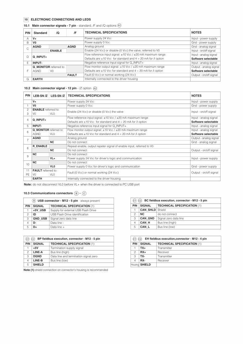
EH fieldbus execution,connector - M12 - 4 pin
PIN SIGNAL TECHNICAL SPECIFICATION (1)1 TX+ Transmitter2 RX+ Receiver3 TX- Transmitter4 RX- Receiver
Housing SHIELD
BC fieldbus execution, connector - M12 - 5 pin
PIN SIGNAL TECHNICAL SPECIFICATION (1)1 CAN_SHLD Shield2 NC do not connect3 CAN_GND Signal zero data line4 CAN_H Bus line (high)5 CAN_L Bus line (low)
USB connector - M12 - 5 pin always present
PIN SIGNAL TECHNICAL SPECIFICATION (1)1 +5V_USB Supply for external USB Flash Drive2 ID USB Flash Drive identification3 GND_USB Signal zero data line4 D- Data line -5 D+ Data line +
BP fieldbus execution, connector - M12 - 5 pin
PIN SIGNAL TECHNICAL SPECIFICATION (1)1 +5V Termination supply signal2 LINE-A Bus line (high)3 DGND Data line and termination signal zero4 LINE-B Bus line (low)5 SHIELD
10.3 Communications connectors -
Note (1) shield connection on connector’s housing is recommended
10 ELECTRONIC CONNECTIONS AND LEDS
V+V0AGND AGND
ENABLE
Q_INPUT+
INPUT-Q_MONITOR referred to:AGND V0
FAULTEARTH
AB
C
D
E
F
G
Input - power supplyGnd - power supplyGnd - analog signalInput - on/off signalInput - analog signalSoftware selectableInput - analog signalOutput - analog signalSoftware selectableOutput - on/off signal
TECHNICAL SPECIFICATIONS NOTESStandard /Q /F
Power supply 24 VDC
Power supply 0 VDC
Analog groundEnable (24 VDC) or disable (0 VDC) the valve, referred to V0Flow reference input signal: ±10 VDC / ±20 mA maximum rangeDefaults are ±10 VDC for standard and 4 ÷ 20 mA for /I optionNegative reference input signal for Q_INPUT+Flow monitor output signal: ±10 VDC / ±20 mA maximum rangeDefaults are ±10 VDC for standard and 4 ÷ 20 mA for /I optionFault (0 VDC) or normal working (24 VDC)Internally connected to the driver housing
10.1 Main connector signals - 7 pin - standard, /F and /Q options
PIN
10.2 Main connector signal - 12 pin - /Z option
Note: do not disconnect VL0 before VL+ when the driver is connected to PC USB port
123
4
5
6
7
8
9
10
11PE
V+V0ENABLE referred to:V0 VL0
Q_INPUT+
INPUT-Q_MONITOR referred to:AGND VL0AGND
NCR_ENABLE
NCNC
VL+NC
VL0FAULT referred to:V0 VL0EARTH
Power supply 24 VDC
Power supply 0 VDC
Enable (24 VDC) or disable (0 VDC) the valve
Flow reference input signal: ±10 VDC / ±20 mA maximum rangeDefaults are ±10 VDC for standard and 4 ÷ 20 mA for /I optionNegative reference input signal for Q_INPUT+Flow monitor output signal: ±10 VDC / ±20 mA maximum rangeDefaults are ±10 VDC for standard and 4 ÷ 20 mA for /I optionAnalog groundDo not connectRepeat enable, output repeter signal of enable input, referred to V0Do not connectDo not connectPower supply 24 VDC for driver’s logic and communicationDo not connectPower supply 0 VDC for driver’s logic and communication
Fault (0 VDC) or normal working (24 VDC)
Internally connected to the driver housing
Input - power supplyGnd - power supply
Input - on/off signal
Input - analog signalSoftware selectableInput - analog signalInput - analog signalSoftware selectableOutput - analog signalGnd - analog signal
Output - on/off signal
Input - power supply
Gnd - power supply
Output - on/off signal
PIN TECHNICAL SPECIFICATIONS NOTESLEB-SN /Z LES-SN /Z

ZM-5PF ZM-5PF/BP ZM-4PM/EH
ZM-5PM ZM-5PM/BP ZM-4PM/EH
CANopen (BC)
PROFIBUS DP (BP)
EtherCat (EH)
MODEL CODES OF MAIN CONNECTORS AND COMMUNICATION CONNECTORS - to be ordered separately12
VALVE VERSION
CONNECTOR CODEZM-7P (IN) ZM-12P (IN)
ZH-7P (IN) ZH-12P (IN)
PROTECTION DEGREE IP67
LEBLES
LEB /ZLES /Z
only for LES
DATA SHEET GS208, GS210, K500
A3 A4
CONNECTORS11
B
A1 A2
A3 A4
ZH-12P
ZM-7P ZM-12P
ZH-7P
ZM-5PM/BPZM-5PM
ZM-5PF
ZM-4PM/EH
ZM-5PF/BPInput
Output
12 pin (Metallic)7 pin (Metallic)
MA
IN C
ON
NE
CT
OR
SFI
ELD
BU
S C
ON
NE
CTO
RS
Note: the use of metallic connectors is strongly recommended to meet EMC performance
12 pin (Plastic)7 pin (Plastic)
Input
Output
Input / Output
L1 L2 L3
A
A A
A
A
A
A2A
A
A
Note: connectors front view
MAIN CONNECTOR
OUTPUT FIELDBUS
CONNECTOR
USB(female)
EtherCAT(female)
CANopen(male)
12 PIN MAIN CONNECTOR(male)
7 PIN MAIN CONNECTOR(male)
EtherCAT(female)
CANopen(female)
PROFIBUS DP(male)
PROFIBUS DP(female)
INPUT FIELDBUS
CONNECTOR
PE
DIAGNOSTICLED
LED FUNCTION DESCRIPTION
-NP, -BC, -BP -EH EtherCAT
L1 VALVE STATUS LINK/ACTL2 NETWORK STATUS NETWORK STATUSL3 SOLENOID STATUS LINK/ACT
USBCOMMUNICATION(always present)
L
L
USBCOMMUNICATION(always present)
MAIN CONNECTOR
LEB
10.5 Connections layout
LES
LEB
LES
E-C-SB-USB/M12USB CABLEcable lenght 4 m
FS330

Size
16
Fastening boltsclass 12.9
N°4 M8x90
Tightening torque35 Nm
Mass (Kg)
5,6 6,2
14 FASTENING BOLTS and VALVE MASS
253240
N°4 M12x100N°4 M16x60N°4 M20x70
125 Nm300 Nm600 Nm
8,210,916,7
8,8
11,217,3
Size
50
Fastening boltsclass 12.9
N°4 M20x80
Tightening torque
600 Nm
Mass (Kg)
23,9 24,6
6380100
N°4 M30x120N°8 M24x80N°8 M30x120
2100 Nm1000 Nm2100 Nm
4471,6122,5
44,6
72,2123,1
LIQZPLIQZO
15 MOUNTING SURFACE AND CAVITY - see table P006 for detailed dimensions
13
Mounting surface
Cavity
ød1 ød2 ød3max
ød4max L1 L2 L3 L4 L5 L6 L7 U W
+0,10
+0,10
+0,10
+0,10
+0,10
+0,20
+0,10
+0,10
+0,10
+0,10
+0,10
+0,10
+0,10
+0,20
+0,20
+0,20
Size
16
25
32
40
50
63
80
100
0,03
0,03
0,03
0,05
0,05
0,05
0,05
0.05
2
2,5
2,5
3
3
4
5
5
2
2,5
2,5
3
3
4
5
5
20
30
30
30
35
40
40
50
42,5
57
68,5
84,5
97,5
127
170,5
205,5
54
70
83
102
117
150
200
239
56
72
85
105
122
155
205
245
43
58
70
87
100
130
175
210
22,5
27
38,5
54,5
62,5
87
100
120
16
25
32
40
50
63
80
100
25
34
45
55
68
90
110
135
32
45
60
75
90
120
145
180
0,05
0,05
0,1
0,1
0,1
0,2
0,2
0.2
Sizes A
2
4
6
7,5
8
12,5
-
-
B
12,5
13
18
19,5
20
24,5
-
-
C
23
29
35
42,5
50
62,5
-
-
D
46
58
70
85
100
125
-
-
E
48
62
76
92,5
108
137,5
-
-
F
46
58
70
85
100
125
-
-
G
23
29
35
42,5
50
62,5
-
-
Jmin
-
-
-
-
-
-
250
300
K
-
-
-
-
-
-
200
245
Lmin
65
85
102
125
140
180
-
-
M
M8
M12
M16
M20
M20
M30
M24
M30
ØN
4
6
6
6
8
8
10
10
ØPmax
4
6
8
10
10
12
16
20
R
22
30
38
46
46
66
50
66
Smax
8
8
8
8
8
8
8
10
T
2
4
6
7,5
8
12,5
-
-
V
48
62
76
92,5
108
137,5
-
-
16
25
32
40
50
63
80
100
Sizes 16 ÷ 63
Size 80, 10035° 22.5°
45°
PROGRAMMING TOOLS - see table GS500
Valve's functional parameters and configurations, can beeasily set and optimized using Atos E-SW programmingsoftware connected via USB communication port to thedigital driver. E-SW software is available in different versionsaccording to the driver’s fieldbus interface: NP (not present) E-SW-PS, BC (CANopen) E-SW-BC, BP (PROFIBUS DP) E-SW-BP and EH (EtherCAT) E-SW-EH.
/S/S
For fieldbus versions, E-SW software permits valve's parameterizationthrough USB communication port also if the driver is connected to the centralmachine unit via fieldbus.
USB connection
TES
TEB
E-C-SB-USB/M12 cable
WARNING: drivers USB port is not isolated!Use of E-A-SB-USB/OPT isolator adapter is highly recommended for PC protection.
E-A-SB-USB/OPT isolator

100x1005
30
105
125x125
39
120
LIQZO-LEB-162LIQZO-LES-162
65x655 146
75
98
16 INSTALLATION DIMENSIONS [mm]
FS330
260
LIQZO-LEB-252LIQZO-LES-252
LIQZO-LEB-322LIQZO-LES-322
LIQZO-LEB-402LIQZO-LES-402
260
260
260
146
146146
85x855
8095
5
218.5
15 151515
� �
� �
92 92
92 92
Note: for mounting surface and cavity dimensions, see section and table P00615
� Space to remove the 7 or 12 pin main connector. For main and communication connectors see section ,11 12

LIQZP-LEB-502LIQZP-LES-502
140x140
49
129
317
5 146
180x180
76
142
336
5
12/14
LIQZP-LEB-632LIQZP-LES-632
LIQZP-LEB-802LIQZP-LES-802
LIQZP-LEB-1002LIQZP-LES-1002
150
45
162
356
Ø250 150
70
178
387
Ø297 150
Note: for mounting surface and cavity dimensions, see section and table P00615
15
15
15
� Space to remove the 7 or 12 pin main connector. For main and communication connectors see section , 11 12
� �
�
105
15
�
128
128
140