Properties of composite Ti(NCO) layers formed on tool steel under glow discharge conditions
4
Surface and Coatings Technology 94-95 (1997) 268-271 Properties of composite Ti(NC0) layers formed on tool steel under glow discharge conditions S.K. Kima**, T. Wierzchonb, JR Sobieckib Abstract Recently, metallo-organic compounds have become the donors of titanium in the PACVD process because a chlorine atmosphere is to be avoided. A Ti(NC0) layer was formed on tool steel by using titanium tetraisopropoxide, hydrogen and nitrogen under glow discharge conditions. This process was combined with the plasma nitriding process to obtain composite Ti(NC0) layers on tool steel. The layers thus obtained had high hardness, good wear and corrosion-resistant properties. Detailed results on the structure and properties of this layer are presented. 0 1997 Elsevier Science S.A. Kq~orcls: PACVD process; Ti(NC0) layer; Glow discharge 1. Introduction The prospects of further development of surface engi- neering lie in new low-temperature CVD techniques for the deposition of hard surface layers such as the plasma- assisted (PA) or pulse plasma CVD methods [l-3]. In the PACVD process, the gaseous medium is activated electri- cally as well as thermally, which permits a significant reduc- tion of the deposition temperature. In the conventional PACVD process, the layers produced usually contain chlor- ine because Tic& is used as a common precursor. The chlor- ine present in the layer causes deterioration of the layer’s mechanical properties and increased stress in the layer [4,5]. In the present work, a mixture of titanium tetraisopropoxide, hydrogen and nitrogen was used, instead of TiCI+ to obtain a Ti(NC0) layer. Plasma nitriding was combined with the Ti(NC0) PACVD coating to produce composite layers of the nitrided layer and Ti(NC0) layer on SKDll tool steel which showed good resistance to wear and corrosion. 2. Experimental methods The composite layers built of a nitrided layer covered * Corresponding author, Tel.: ~522 259 2228; fax: i522 77 3522: e-mail: [email protected] with a Ti(NC0) layer were produced in a universal appara- tus designed for plasma-assisted thermo-chemical treat- ments. The apparatus permits plasma diffusion processes and PACVD processes to be carried out in various gaseous atmospheres. It also enables the composirion of gaseous mixture to be modified during the process 161.Plasma nitrid- ing was done in an N#l* atmosphere and subsequently Ti(NC0) layers were produced by the introduction of Ti(OC3H7)4 vapors mixed with N2/H2 and by varying the current-voltage parameters. Plasma nitriding was done at 5OO”C, 300 Pa for SKDll steel. The deposition of the Ti(NC0) layer was done for 2 h at 52O”C, 400 Pa for SKDll steel. The composite layers were formed on SKDll steel (1.5% C, 11.5% Cr, 0.8% MO, 0.9% V). The content of Ti(OC3H7)4 vapor in the gas atmosphere was below 10% by volume. The metallographic specimens were etched with nital. Hardness of the layers was measured using a micro Vickers hardness tester (Mitutoyo, MVK-Hl. Japan) with a load of 50 g. Concentration gradients of ele- ments present in the nitrided + Ti(NC0) composite layer were examined with EPMA (EPMA-1400, Shimazu). X- Ray investigations were made using a Philips 1700 X-ray diffractometer equipped with Cu lamp (CuK = 1.54 nm). The resistance to frictional wear was examined using a ball-on-disc-type wear tester. The resistance to corrosion of the layers was examined by the potentiodynamic method in a 0.5 M NaCl solution. 0257~8972/97/$17.00 0 1997 Elsevier Science S.A. All rights reserved PII 50257.8972/97)00350-2
Transcript of Properties of composite Ti(NCO) layers formed on tool steel under glow discharge conditions

Surface and Coatings Technology 94-95 (1997) 268-271
Properties of composite Ti(NC0) layers formed on tool steel under glow discharge conditions
S.K. Kima**, T. Wierzchonb, JR Sobieckib
Abstract
Recently, metallo-organic compounds have become the donors of titanium in the PACVD process because a chlorine atmosphere is to be avoided. A Ti(NC0) layer was formed on tool steel by using titanium tetraisopropoxide, hydrogen and nitrogen under glow discharge conditions. This process was combined with the plasma nitriding process to obtain composite Ti(NC0) layers on tool steel. The layers thus obtained had high hardness, good wear and corrosion-resistant properties. Detailed results on the structure and properties of this layer are presented. 0 1997 Elsevier Science S.A.
Kq~orcls: PACVD process; Ti(NC0) layer; Glow discharge
1. Introduction
The prospects of further development of surface engi- neering lie in new low-temperature CVD techniques for the deposition of hard surface layers such as the plasma- assisted (PA) or pulse plasma CVD methods [l-3]. In the PACVD process, the gaseous medium is activated electri- cally as well as thermally, which permits a significant reduc- tion of the deposition temperature. In the conventional PACVD process, the layers produced usually contain chlor- ine because Tic& is used as a common precursor. The chlor- ine present in the layer causes deterioration of the layer’s mechanical properties and increased stress in the layer [4,5]. In the present work, a mixture of titanium tetraisopropoxide, hydrogen and nitrogen was used, instead of TiCI+ to obtain a Ti(NC0) layer. Plasma nitriding was combined with the Ti(NC0) PACVD coating to produce composite layers of the nitrided layer and Ti(NC0) layer on SKDll tool steel which showed good resistance to wear and corrosion.
2. Experimental methods
The composite layers built of a nitrided layer covered
* Corresponding author, Tel.: ~522 259 2228; fax: i522 77 3522: e-mail: [email protected]
with a Ti(NC0) layer were produced in a universal appara- tus designed for plasma-assisted thermo-chemical treat- ments. The apparatus permits plasma diffusion processes and PACVD processes to be carried out in various gaseous atmospheres. It also enables the composirion of gaseous mixture to be modified during the process 161. Plasma nitrid- ing was done in an N#l* atmosphere and subsequently Ti(NC0) layers were produced by the introduction of Ti(OC3H7)4 vapors mixed with N2/H2 and by varying the current-voltage parameters. Plasma nitriding was done at 5OO”C, 300 Pa for SKDll steel. The deposition of the Ti(NC0) layer was done for 2 h at 52O”C, 400 Pa for SKDll steel. The composite layers were formed on SKDll steel (1.5% C, 11.5% Cr, 0.8% MO, 0.9% V). The content of Ti(OC3H7)4 vapor in the gas atmosphere was below 10% by volume. The metallographic specimens were etched with nital. Hardness of the layers was measured using a micro Vickers hardness tester (Mitutoyo, MVK-Hl. Japan) with a load of 50 g. Concentration gradients of ele- ments present in the nitrided + Ti(NC0) composite layer were examined with EPMA (EPMA-1400, Shimazu). X- Ray investigations were made using a Philips 1700 X-ray diffractometer equipped with Cu lamp (CuK = 1.54 nm). The resistance to frictional wear was examined using a ball-on-disc-type wear tester. The resistance to corrosion of the layers was examined by the potentiodynamic method in a 0.5 M NaCl solution.
0257~8972/97/$17.00 0 1997 Elsevier Science S.A. All rights reserved PII 50257.8972/97)00350-2
S.K; Kim et ai. /Surface and Coatings Technology 94-95 (1997) 268-271 269
(a)
(b)
id Fig. 1. Micrographs of (a) the nitrided layer, (b) the Ti(NC0) layer, and (c) the nitrided i- Ti (NCO) composite layer on SKDll steel.
Table 1
Microhardness of layers formed in the Ti(OC,H,), + N#& atmosphere
Steel grade Type of layer and microhardness, Hi0,05
SKDll Nitrided layer, Ti(NC0) layer, Nitrided i- Ti(NC0) i442 1250 layer, 1950
3. Results
Ti(NC0) layers and nitrided + Ti(NC0) composite layers were obtained under the conditions described above. Micrographs of (a) the nitrided layer, (b) Ti(NC0) layer, and (c) nitrided + Ti(NC0) composite layer on SKDll steel are shown in Fig. 1. The Vickers microhard- ness of three types of layers are given in Table 1. These are the averages of five values taken from different places of the samples. As can be seen from the Table 1, the Vickers microhardness of the nitrided + Ti(NC0) composite layer increased significantly by combining the nitrided layer with the Ti(NC0) layer.
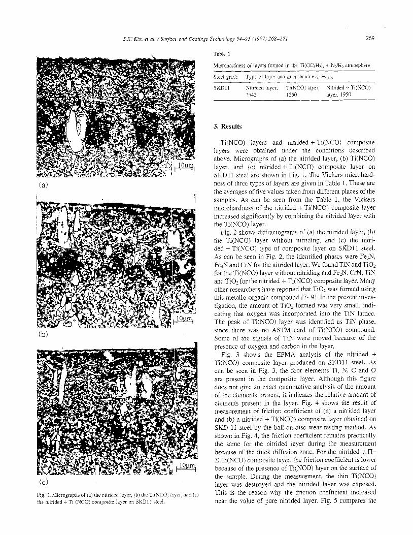
Fig. 2 shows diffractograms of (a) the nitrided layer, (b) the Ti(NC0) layer without nitriding, and (c) the nitri- ded + Ti(NC0) type of composite layer on SKDll steel. As can be seen in Fig. 2, the identified phases were FesN, Fe4N and CrN for the nitrided layer. We found TIN and TiO1 for the Ti(NC0) layer without nitriding and Fe2N, CrN, TIN and Ti02 for the nitrided + Ti(NC0) composite layer. Many other researchers have reported that TiOz was formed using this metallo-organic compound [7-91. In the present inves- tigation, the amount of TiOz formed was very small, indi- cating that oxygen was incorporated into the TIN lattice. The peak of Ti(NC0) layer was identified as TiN phase, since there was no ASTM card of Ti(NC0) compound. Some of the signals of TiN were moved because of the presence of oxygen and carbon in the layer.
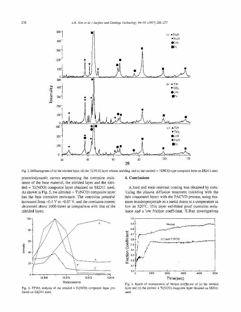
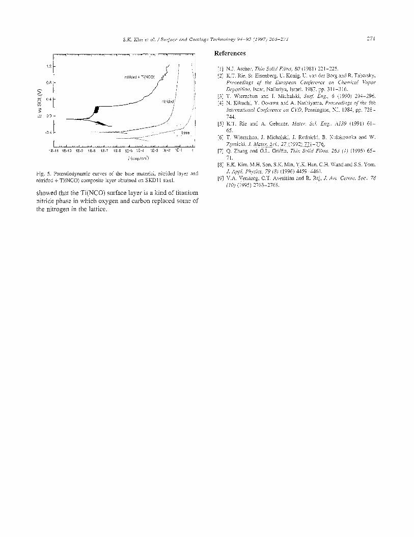
Fig. 3 shows the EPMA analysis of the nitrided + Ti(NC0) composite layer produced on SKDll steel. As can be seen in Fig. 3, the four elements Ti, N, C and 0 are present in the composite layer. Although this figure does not give an exact quantitative analysis of the amount of the eIements present, it indicates the relative amount of elements present in the layer. Fig. 4 shows the result of measurement of friction coefficient of (a) a nitrided layer and (b) a nitrided + Ti(NC0) composite layer obtained on SKD 11 steel by the ball-on-disc wear testing method. As shown in Fig. 4, the friction coefficient remains practically the same for the nitrided layer during the measurement because of the thick diffusion zone. For the nitrided .*.I% C Ti(NC0) composite layer, the friction coefficient is lower because of the presence of Ti(NC0) layer on the surface of the sample. During the measurement, the thin Ti(NC0) layer was destroyed and the nitrided layer was exposed. This is the reason why the friction coefficient increased near the value of pure nitrided layer. Fig. 5 compares the
270 S.K. Kim rr cd. /Sut$uce and Confings Technology 94-95 (1997) 268-271
a
Fig. 2. Diffractograms of (a) the nitrided layer, (b) the Ti(NC0) layer without nitriding, and (c) the nitrided + Ti(NC0) type composite layer on SKDl 1 steel.
potenriodynamic curves representing the corrosion resis- tance of the base material, the nitrided layer and the nitri- ded + Ti(NC0) composite layer obtained on SKDl1 steel. As shown in Fig. 5, the nitrided + Ti(NC0) composite layer has the best corrosion resistance. The corrosion potential increased from -0.4 V to -0.07 V, and the corrosion current decreased about 1000-times in comparison with that of the nitrided layer.
00 13.808 13.810 13.812 13.814
Thickness(mm)
Fig. 3. EPMA analysis of the nitrided + Ti(NC0) composite layer pro- duced on SKDl 1 steel.
4. Conclusions 4. Conclusions
A hard and wear-resistant coating was obtained by com- bining the plasma diffusion treatment (nitriding with the thin compound layer) with the PACVD process, using tita- nium tetraisopropoxide as a metal donor at a temperature as low as 520°C. This layer exhibited good corrosion resis- tance and a low friction coefficient. X-Ray investigations
A hard and wear-resistant coating was obtained by com- bining the plasma diffusion treatment (nitriding with the thin compound layer) with the PACVD process, using tita- nium tetraisopropoxide as a metal donor at a temperature as low as 520°C. This layer exhibited good corrosion resis- tance and a low friction coefficient. X-Ray investigations
1.0 I I
0.8 - 0.8 -
/ 1000
I I 2000 3000
Time(sec) Fig. 4. Result of measurement of friction coefficient of (a) the nitrided layer and (b) the nitrided t Ti(NC0) composite layer obtained on SKDl 1 steel.
S.K. Kim et al. / Surjiice and Conrings Technology 94-95 11997) 268-271
1.2 -
0.8 -
F -
Lir
is 0.4 -
Y Lu 0.0 -
-04 -
I , ,,,, li ,,,,, 1 <,,.,, , ,,,,, d , ,,,,, 1 , ,,, d ,,,, i, I I,.,, d ,,,, 4 ,,,,, 1 , ,,d
IE-II iE-10 159 IE-8 1E-7 IE-6 lE-5 lE-4 IE-3 IE-2 lE-1 ,
i (amdcm2)
Fig. 5. Potentiodynamic cunvs of the base material, nitrided layer and nitrided + Ti(NC0) composite layer obtained on SKDll steel.
showed that the Ti(NC0) surface layer is a kind of titanium nitride phase in which oxygen and carbon replaced some of the nitrogen in the lattice.
References
271
[I] NJ. Archer, I?iii~ Solid Fiinzs, 80 (1981) 221-225. [2] K.T. Rie. St. Eisenbrrg, U. Konig, U. van der Borg and R. Tabersky,
Proceediilgs of the Euiopem Conference on Cheinicd Vapor De,wsifion, Iscar, Nallariya, Israel, 1987, pp, 31 1-3 16.
[3] T. Wierzchon and J. Michalski, Sw$ Eng., 6 (1990) 291-296. [4] N. Kikuchi. Y. Oosawa and A. Nashiyama. Procrrdings of rhe 9th
li~rewafiowl Coi~fitvnce 011 CI’D, Pennington, NJ, 1984, pp. 728-
[5] K.T. P.ie and A. Gebauer, ~Mnrer: Sci. Eizg.. AI39 (1991) 61- 65.
[6] T. Wierzchon, J. Michalski, J. Rudnicki, B. Kulakowska and W. Zyrnicki, .I. MareGci., 27 (19921221-776,
[7] Q. Zhang and G.L. Griffin, Thin Solid fiims, 263 (1) (1995) 65- 71.
[8] E.K. Kim,M.H. Son, S.K. Min, Y,.K. Han, C.H. Wand and S.S. Yom, J. A@. Physics, 79 (8) (1996) 4459-a61,
[9] V.A. Versteey, CT. Avesisian and R. Raj, .I. A/n. Germ. Sot., 78 (IO) (1995) 2763-2768.