Monitoring of in-Service Non Ceramic Insulators and Underground Cables

&,. ,:,.
—.
.._:_ :--
=.2-’--,,--.- ,.
. .
A
REPORT No. 63 *
a
PROPERTIES AND PREPARATION OFCERAMIC INSULATORS
SPARK PLUGS
v
NATIONAL ADVISORY COM.MITI!EE
FOR AERONAUTICS
FOR
PREPRINT FROM I?WJ!HANNUALREPORT
wA82mTGToNGOVERNMENT PR2W1’2NG OFFICE
1920
,
.
*
https://ntrs.nasa.gov/search.jsp?R=19930091115 2018-07-18T13:52:55+00:00Z

—..
,
REPORT No. 53
PROPERTIES AND PREPARATION OFCERAMIC INSULATORS FOR
SPARK PLUGS
v
NATIONAL ADVISORY COMMITTEE
FOR AERONAUTICS
PREPRINT FROM FIFTH ANNUALREPORT
WASHINGTON
GOVERNMENT PRINTING OFFICE
1920
REPORT No. 53.
PROPERTIES AND PREPARATION OF CERAMICINSULATORS FOR SPARK PLUGS
Part I.–METHODS OF MEASURING RESISTANCE OF INSULATORSAT HIGH TEMPERATURES
By F. B. SILSF!?JE and R. K. HONAhiAN
Part 11.–ELECTRICALRESISTANCE OF VARIOUS INSULATING MA-TERIALS AT HIGH TEMPERATURES
By 1?. K. HONA,MAh’ and E. L. FONSECA
Part 111.—PREPARATIONAND COMPOSITION OF CERAMIC BODIESFOR SPARK-PLUG INSULATORS
BY A. V. BLXIKIIfGl?R
Part W.-CEMENTS FOR SPARK-PLUG ELECTRODESBy H. F. STALEY
159827-20—1
,

REPORT No. 53.PART I.
—.
METHODS OF MEASURING RESISTANCE OF INSULATORS AT HIGH TEMPERATURES.’
By F. B. SILSBEE and R. K, HONAMAN. .
>RJkJMi%
This report describes in some detail the preliminary experiments which,were made on theconductivity of spark-plug insulators in order to develop a satisfactory comparative methodfor testing various materials. The measurements were made at temperatures between 2000 and9000 C, and with both alternating and direct current at voltages as high as 2,OOOvolts.
The results obtained confhmed the experiments of earlier observers at lower temperaturesin indicating a very rapid decrease of resistance with increase of temperature in porcelain,mica, fused silica, and similar materials. This decrease is, however, a gradual one and thereis no definite temperature at which the material suddenly changes its properties. The resultsof conductivity measurements can be most conveniently expressed by stating the temperature(2’,) at which the, material has the arbitrarily selected resistivity of one megohm per centimetercube. Table 1 gives the values of this constant for various substances.
The measurement with direct current showed the presence of. disturbing po~arizationeffects which make the apparent resistance of the specimen vary with the magnitude and ‘time ofapplication of the measuring voltage. This effect can be eliminated by the use of alternatingcurrent in, making the measurements and the later work on a wide variety of substances, the
“ results of tvhich are given in Part II of this report, was done by this latter method.There is a wide field for further investigation of this subject, as the mechanism of conduction
in this class of materials is very complex, ... ..
INTRODUCTION.
The purpose of this report is to describe some measurements carried out at the Bureau ofStandards during the past two years, on the resistance of various insulating materials at hightemperatures. This work was undertaken with a view to studying the relative merits of variousinsulators for use in sparkplugs, and in particular to assist the ceramic laboratory of the bureau indeveloping improved porcelain bodies for this purpose. The method finally adopted as a resultof this work for the comparative testing of materials is described briefly in Iteport No. 51,Part III, the results of a large number of measurements on a wido variety of materials are givenin Report hTo. 53, Part 11, and the development of the ceramic side of the investigation is givenin Report No. 53, Part III. The present report will be confined to a description of the various”phenomena observed in the experiments which led to the method finally adopted.
The electrical and thermal conditions under which a spark plug is required to operatediffer considerably with the type of gasoline engine used. ,Measurements with embedded thermo-couples have shown that the temperature of the body of the insulator within the metal shellseldom exceeds 250° C. in water-cooled engines. The tip of the inner end, however, may reachtemperatures as high as 900° to 1,000° C, It therefore, appeared desirable to study the resis-tivity of the specimens in the range of temperature between 2000 and 900° C.
1ThisReport was confiderrtiially circulated during the war as Bureau of Standards Aeronautic Power I’lauts Report No. 1S.
3

4 ANNUAL REPORT NATIONAL A13VISORY COMMITTEE I?OR AERONAUTICS.
The electrical dresses applied to a spmk-plug insulator by the a-i-erago magneto or bnt tcrycoil ignition system used for firing gasoline engines are quite peculiar rmd cliificult to duplimt e inany method of numsurmnent. The cycle of operation (see Report No. 5S, Part 1) following thQopening of the primary brwdmr contacts consists of a rapid rise of the potw]tia] npplicd to tlwspark plug from zero t.o a -value sufllcicnt to break down the spark gap in tho engine cylinder.The break-clown voltage is of the order of 6,000 ~olts and is reached in a few hundred thou-sandths of a second. After this a compurutively low voltage (S00 volts) nminttiins the electricarc between the spark points ancl ltists for K few thowmndths of a second. Sinm tho intervalbetween sparks is of the order of 0.1 second, it will be seen that the average voltiigc ap])lie.cl over
a complete cycle is quite low and has been found to be approximately 150 -iolts. ‘nose peculiarelectrical condi tions sho LIIC1be kept in mind when considering the various methods of mmsurc-ment described below.
The materials studied in this investigation included porcelains, gltiss, st eatite, mira, andfused silica, as these constitute the only class of substances sufficiently heat resisting for uscin spark plugs. While the detailecl studies of polarization, etc., described in this rrport. weromade on only a few of the porcelain samples, the same efforts seemed to bo present to grcwtoror IGSSdegree in all cases and the process of conduction is probaldy similar in all of them. Thework of earlier invest igatorsl has shown the complex nature of the phmxnena, but as y ct. nocomplete and satisf uctory theory has been workecl out to account for them.
APPARATUSAND SPECIMENS.
Most of t,lle work reported in this paper wus done on cwp-shaped spwi mcns simihr t(J tht?
standard test piece NTO.1, adopted by tho A. S. T. M., except thtit the side walls were of uniformthickness. The cross section of this specimen is shown in figure 1. The prinripnl d~atltag~sof this type of specimen are:
(1) The conduction takes place through the bottom of the cup, which is of W_initoand easily measured dimensions.
(2) The large area and small thickness of the bottom insure a relatively large current.even with material of high resistivity.
(3) The path over the rim of the cup for any surftice lealwge is relatively long.(4) A satisfactory contact can be made betweeu the specimen and the clectrodw lq-
imrnersing the bottom of the cup in a conducting fluid (in these exptwiments,meltecl solder) and by inserting seine of this fluid inside tho cup to f(ml ~ thoupper electrode.
These. cup specimens wero used in the furnace shown in figure 2. Tlw heating coil insvrtcilin the plug below t,he specimen was found necessary to compenwito fw’ the flow of hcut throughthe bottom of the furnace. By propw adj ustmenfi of the relative amounts of current throughthe main winding and through this additional coil, tho tempemt urcs it]side and outsid(~ thr rupcould be equalized. These temperatures were mmsurccl by two cop]]c~r-c(}llsta~~t~ltlthwnm-couples, one of which was inserted in a closed porcelain tube which dippwl bulow the surfacoof the solder in the interior of the cup, while the other was cmbcddcd in the st c~’1cup ro]lt ail~il~gthe solder below the specimen. Readings of the resistance were taken only when thcw two
thermocouples showed subst mutitilly equal temperatures.In cases where cup spocimms wore not ava.ilablc+ measuromonts wwo mwlo on tisscmblcd
sparli plugs, and also on spark-plug insulators , and on short piww of tU]JiIl& In llll?sc (’asl!s
the conduction took place between a central electrode amd oithw the shd.1 of tho spark plugor a band of platinum deposited arouncl the center of the outside of t,ho insulator or tul )c. Thonmasuremcmts with this typa of specimen wore definite in indicating tho rwistanco of t.hc speci-men, but owing to the uncertainty as to the area of contact and the location of the linw of cur-rent” flow it is cliffkult from such data to computo with accuri~cy tho t ruo rwistivity of t.htimaterial.
1~ra~,T.,Phil. Meg. ser. 5, vOI. 10, P. 226,18E0. Kinnimn, C, S., Pror. Am. ~eramic SOS.17, p. 422, 191s.Haworth, IL F., Proc. Roy. Sot. Land. A 81, p. 221,1908, Poole, H. H., Phil. Msg. 34, p. 1S3,1917.SomemflIe, A. A., Phys. Rev. 31, p. 261,1910. ~rw, P. M, Tram, Am. Ekctrechem. SQC.,WY 5, 1918,Chmphcll, Nm. Phys. I& 11,p. 207,1914.
—

PROPERTIES AND PREPARATION OF CERAMICl INSULATORS FOR SPARK PLUGS. 5
I I I
I I
g /—
..-—I 2.!5mm
FIG. 1.—Porcelain test specimen,
+ &/ecAx7!e
Fig. 3.
.
—
FIG, 4,—Connectionefor high voltage D, 0, measurements.

1 Oa
i I
/\
flkhvfnemwao/ Am-d
t t 11--4 Ulu-willl
nlll-u
f4_,. [ qLed 7%/k57hwn?ds n.-lLLJ_
FIG. 2. “
6-
7iWWi Mu
260
604ffm w
\ .?W6
5ZWM 200$$
f!m .ysI z
iz<
$4J4010c \ ,
/
16U”;f
..u Ma:$$? /
~
.2J&#W 1208$
I
Kb
vARlA770/VOF/7i5/SZ4 NCE \W/T14 TEMPERATURE
s00 Vo/fS 60Cyd@ Cup5../.
\
IM 4.
/- ResjsfonCe Vers. 7Zmp.z- — 2- ~ Vers. *mperofure.
I80
3 - Log,. R Vers. Z+mp.
—.. — \ 60
I04L?W/
\ 4a
\ w
J
o 104~ w 40D w ~PlofNo. S Tcmperofu~ ii7 -C

PROPERTIES AND PREPARATION OF CERAMIC INSULATORS FOR SPARK PLUGS.~
For specimens of this shape the electric furnace shown in figure 3 was used, and tempera-tures were indicated by a single thermocouple placed in an iron plug which supported the9pecimf3n.
For reducing the results of either type of specimen from the observed resistance to a basisof the resistivity of the material the factors connecting these two quantities were computmdfrom the dimensions of the specimens. The rc%istivity is obtained by multiplying theobserved resistance by the factor K, where for the cup specimen
T d2.—‘c–4 t (1)
and d is the diameter of the bottom of the cup and t the thickness of the cup in centimeters,For the tubular specimen
K= “21r12.30 ]oglO~z (approx. 2)
l?,
where Z equals the length of the external conducting band measured parallel to the” length ofthe specimen, and R2 and RI arc+,respectively, the external and internal radii of the insulator.
In most of the work the resistances were measured by reading a voltmeter connoctedacross the specimen and an ammeter in seri& with it ancl taking the quotient of these values asthe resistance. As will be seen from the following, a wide variety of sources was used to providethe applied voltage, and the indicating instruments were correspondingly varied in character.
VARIATIONOF RESISTANCE WITH TEMPERATURE.
The first experiments were carried out with an appli~d direct-current voltage of about2,ooO volts, which was obtained by rectifying with a kimotron a 3,000-cycle voltage suppliedfrom a step-up transformer. The connections used to obtain this rectification and to reduce thefluctuations in the resulting continuous voltage are shown in figure 4. This rather complicatedsystem was chosen in an attempt to duplicate to some extent the voltages existing in ignitionsystems, a.ncl, although this source of voltage was later abandoned, the data obtained with itbrought out the salient facts in regard to this type of conduction. The most striking of thesefacts, as verified by other measurements made later, is the very rapid clocrease in resistance ofthe specimen with increase in tt~mperature. This variation amounts to approximately 2 per centpes degree centigrade at all temperatures, If the results are expressed by plotting resistancem. tempcratum, or conductance VS. temperature (see plot 5), the resulting curves are so steepas to render it impracticable to express the data over an extended temperature range by asingle curve. It is found, however, that by plotting the common Iogaritlun of the resistanceagainst temperature, as is done in curve No .“III, plot 5, and in plot 6 a convenient line ofslight curvature is obtained, It will be men from this plot that if this curvature is neglected,the results can be represented approximately by the equation
Log10R=a–5t (3)
This method of expressing the results is very convenient in reducing the data to a basis of “resistivity, since combining the relation
P=Kx R (4)with equation (3) one obtains
LoglOp= a +Iogl, h’– b t = c– b t (5)
In this equation L and c are constants of the material and are independent of the shapeand size of the specimen used. Unfortunately, however, the values obtained for one of theseconstants depends very markedly upon tho other, so that a slight error in one will cause a com-pensating change in the other, They are, therefore, not well suited for comparing the relativemerits o~ the ~ifferentcompute an ‘reffective
183136—20—2
materials and for this latter purpose it has been found convenient totemperature” (T.), which is defined as the temperature at which the

8 ANN”U& REPORT NATIONAL ADVISORY COMMITTEE FOR AERONAUTICS.
material has the arbitrarily selecteii resistivity of 1 megobm per. centinmtw cube, and whichmay be computed from the equation
T,= c~6 [6)
This value of T, rangas from 350° in the poorer grades of porcelain up to SOOOfor fusedsilica, and is a convenient index of the value of the material as an insulator tit. high tmnprwatums.
An inspection of these resistance-temperature cur~es shows a completo ahsonm of anycritical temperature at which the material undergoes an abrupt chwnge in its resist imco. Thisshows the error of tho commonly accepted idea that, porcelain lnwaiis tiown ami bwotntis con-ducting at a definite temperature. This belief probably originated from cwpmimcnts in whichthe temperature of a porcelain sample was gradually raised while being continuously sul~jortcxlto an applied voltage. The effect of the current flowing through the samplo in such cases
Fwould be entirely negligible up to a certain tcnnpertiture at which the power
()~ SIL@kd by
the measuring current became comparable with the rate at, which heat could bo dissipatuil tuthe surrounclings, Owing to the very rapid rate of change of resistance with tcmptuwturej avery slight further increase in temperature would materially decrease tho rosisttuwo find con-
()sequently increase the # loss. L-nlcxs the specimen was in a position to give ofl hmt frwdy
. .to its surroundings the tompcrature would rise rapidly, causing a furthtir derrmso in resist.tmcc,thus loading to an unstable state which would rapidly causo tho fusion of tho mut oriid and thupassago of an arc.. The rapidity of change of resistance wit~ temperature malws this point. ofinstabiWy quite definite, provided all the condit,if ms of the expmiment arc main taino~l con-stant, but this apparent critical temperature will depqnd very greatly upon the c.ont act Imtwconthe specimen ancl the furnace, upon the applied voltage, and the other conditions, so thtit thisis in no sense a specific property of the material.
The magnitude of this heating effect is exemplified by the behavior of u porcelain sampletested when hot—for exampk, at 500° C. At this terupertit.ure, the resistance of a centimetercube of ordinmy porcelain is about 100,000 ohms, and if a ~olt age of only 500 ~olts pcr n~illi-meter (i. e., only about one-twentieth of that required to puncture it while mhij be appliwi,the current flowing will be 50 milliamperes and the power dissipated in the smnple will be 250Wrltts. This will suffice to raise the temperature of the srunple at, a rate of about 100° C. persecond and will cause its rapid ciestlruction.
This heating of the specimen by the measuring current was observed on numerous occasionswhen making tests at 2,000 and 1,000 -rolts, and in each case the samples on remo-ral from thefurnace were found to contain one or more spots whe!e the porcelain lnui. hcen fuswi inio aglass by the intense local heating. In the later work at lower ~oltage this eflect was not present,and readings were taken only when the current was substantially constant.
POLARIZATION.
The early measurements with high voltage direct current showed a number of puzzlingdiscrepancies, such as a Tariation of the apparent resistance with the volt tigc used in nmkingthe measurement and with the time of application of this vo~tage. Plot 7 shows this vnria-tion of resistance with voltage as observed with a porcelain cup specimen. Such (iiscrcpancicsindicated the presence of an additional phenomenon to be reckoned with, which in the ul.wenccof definite knowledge as to its origin was called ‘‘polarizat ion,” anti will be so referred tothroughout this report.
The fundamental manifestation of this so-called, polarization is that if a const+mt (iircct..current voltage be applied to a specimen, the resulting current will ciecrease at- first rapi{ilyand then more gradually, as is indicated in plot 8. lle reduction in current is often equivalentto an increase in resistance by a factor of 10 or 20. If the specimen is allowed to remain at ahigh temperature but without applied -roltage for some tirre, the effect gradually clisappmrs,but a considerable time is required to accomplish this. The disappearance is rcore mmid at

PROPERTIES AND PREPARATION OF CERAMIC INSULATORS FOR SPARK PLUGS. 9
.
44
.81 r , I, I , I ,
.4\.\
LagwR* ZS4‘,0403+. 44*720. Zs4 b -0.0103 c ● 943
.~ ~-=o.olgmeoohm~cmcube L
T—–r-rr-’l 1“, ‘- 7=’3Y”’I“:-r
6\~
,4
. \ ,z
380 \/00 M w 4J0 w
PlofNo.6 Tempen7fure Ii7 ec
‘m--t-t-I I I I I I I
12 \ VARIATIONIJVAPPARENTRE~fSTANCEWNh O.C. Measuring Yolfoge
CUP /8A!1 1. CReadthgs taken ;mmed;b+elyofferopp fi.
PlotNo.7 Volfeqe Applied Plof No.9 Temperature in “C

ANNUAL REPORT NATIONAL ADVISORY COMMITTEE FOR AERONAUTICS.
..tiot M 8 The in Pfinuiss.” ‘
&w
/
POLARIZATION – —-. ac.Reveme.* With
9ACmd O.CSUPEfWOSED.
CUP 288.8 mnp. +Zs=c
2:7
.?80voltsD.c-At A4kd 302 . A C. (.ff-
[ – 7 - - – -
futive.). .
g~
*R“
C.RSIIWM
“~ 5 )
2k
I~4
k .%Mant●o.C.- ~ *AL .
k’
Ic
2 1 I
t/
i [ I A.CRen-av.?dA a c,Adddi
0: I
e, 4 8 /2 & d a Z#flQf t40, It Ttme m Pfinutss

PROPERTIES AND PREPARATION OF CERAMIC INSULATORS FOR SPARK PLUGS. 11
high temperatures than at low. Plot g gives a record of the variation of the apparentresistance of a glass beaker, as measured with 1,000 volts direct current, after various applica-tions and removals of the measuring potential. The course of the experiment is indicated bythe arrows, and the duration of each period of application or of rest is indicated on the curve,The lowest and highest curves give the resistance as observed with very short application ofthe testing -voltage just prior to the polarizing test and on the following clay, respectively,The apparent permanent increase of resistance observed with this specimen serves to explainsome mysterious results obtained at an earlier date, in which one specimen had shown anincrease of resistance to more than twenty tim.e$ its initial value after several successive tests.The fact that an appreciable time is required to obtain a reading, even with quick acting directcurrent indicating instruments, and that during this time the specimen is being polarized, isprobably a complete explanation of the variation of apparent resistance with applied voltage,
sliown in plot 7. If the applied direct-current voltage is suddenly reversed after a specimenhas become polarized to a considerable extent, t~le initial current in the new direction is foundto be approximately equal in magnitude to the original current and much greater than the valueimmediately preceding the reversal. (See plot 10.) This hplies a counter 11. M. F., and anattempt was made to observe such an effect by connecting an electrostatic voltmeter acrossthe specimen. No residual deflection of this meter was observed when the supply current wasremoved, even after long-continued polarization of the specimen. This result is to some extentin contradiction to facts mentioned by other observers.2
A magneto having alternate distributor points of the same polarity connected togetherwas also used as a source of voltage and the polarizing effects found to be in every way similarto those obtained with a steady direct-current source of the same average voltage (150 volts).
When alternating current is applied to a fresh specimen, there is no polarizing effect andthe current remains constant indefinitely, except l~-hen the current is so large as to produceheating of the epecimen. When alternating current is applied to a specimen which has beenpreviously polarized by direct current, the polarization disappears at a more rapid rate than ifthe alternating current had not been applied.
An attempt to throw light on these complex phenomena was made by applying alternatingand direct current simultaneously to a specimen. This was accomplished by connecting atransformer in series with a generator. By opening the primary circuit of the transformer,or the field of the generator, either source of E. h~. F. could be eliminated without opening thecircuit or interfering with the current flOW from the other source. The alternating-currentvoltage was measured across the transfornler terminals with a moving iron voltmeter, and the -direct-current voltage by a d’Arsonval type direc~current voltmeter across the generator.The alternating current through the specimen W~S passed through the moving coil of an electro-dynamometer, the fixed coil of which W~S excited by an alternating Current of constant magni-tude and in the same phase as the alternating voltage applied to the specimen. The directcurrent through the specimen was measured by a direct-current milliammeter connected inseries with the specimen and the dynamometer. With this arrangement, each pair of instru-ments measured only its particular component of the resultant current and voltage and wasnot affected by the presence of the other component. Plot 11 shows the variation withtime during the course of the experiments of the resistances as computed from the two com-
ponents of the current. In this experiment the maximum value of the alternating-currentvoltage was greater than the direct-current voltage, so that the resultant voltage applied tothe specimen reversed in sign during each alternation. Other experiments, in which themaximum alternating voltage Ilras less than the direc~current voltage, and the resultantvoltage was consequently unidirectional) showed substantially the same effects.
Throughout the experiments the temperature was held as nearly constant as possible,but a gradual drift of resistance will be noticed which can be accounted for by a slight changeof temperature. It appears from these results that the resistance of the specimen is sub-stantially the same for both the alternating and direct current for all states of polarization.
: hfax~ell, J. C., Electricity and magnetism, $271, vol. 1, p. 393, 3d ed.

12 ANh’UALRJ3PORTXATIOXALADVISORYCOMMITTJMlWR AERONAUTICS.
Or, in other words, the polmization produced by the direct current offers resistance to thepassage of the alternating current and the depolarization produced by the alternating currentreduces the resistance offered to the passage of the direct current.
When alternating current alone was applied to a fresh specimen, the pcmw factor of thecircuit was found to be substlan tially unity. If, howe-rer, the specimen had recently beenpolarized fiy the application of direct current,, the power factor was somewhat reduced: ~alumas low as 0.9 ha~-ing been observed.
The data described above are quite insu.fllcient for the development of any complete theoryof this polarization! but it would appear that the assumption of a counter E. M. F. is rulccl out ,both by the rxxperiments of combined tdt.ernating and direct current and by the difhulty ofimagining a mechanism capable of producing a counter E. M. F. of the order of sev-erd thousandvolts, which would be required to produce the obsemcd decrease of current-. A possib]c explana-tion may be developed on a basis of the migration away from orle electrode, of the ions ca~.ingthe current,, thus lea~ing a scarcity of ctirriers for the further passngc of current in the orl.gmddirection, but providing a plentiful supply for cuments in the reversed direction. Anothersuggested explanation is the formation of rrsisting films which may COTcr a coneiderable partof the area of the electrodes but which are rem?ily rrmo~’ed by electrolysis on ‘rcwvsnl of thecurrent. Tests made using platinized surfaces as electrodes instewl of the n:eltwl sohkwshowed no difference of beha-rior. It may be noticed in this connection that wl:eu the sampleswere’ rernovecl after cooling, the solidified solder }~clhered firmly to both surfaces of the cupswhich h~d been treated with direct current., but COUIC1he very readily peeled off from spccimemwhich had been tested on alternating current.
DISCUSSION OF METHODS FOR MEASURINGRESISTANCES.
As a result of the data obtained in the preliminmy experiments just cl~scribcd, it, wasdecided to adopt as the most satisfactory methocl for the rapid comparison of diflereut. typesof immlating materials the volt-ameter method, using alternating current. under these condi-t ions the observed resistance is substantially independent of the frequency, -roltageJ and t inmof application, and the convenient values of 60 cycles and 500 voltti were adopted for the laterwork. PlcJt 6 shows typical results obtained by this method and indicates the ngrecmcnkattainable on successive runs even at different volttiges. It should be ~cmembcredj howcvor,that the results thus obtained are for the nmterial in the unpolarized state, tind, when in M-tualuse in ignition system, the material may show a much higher rwis tancc to the unidirectionalimpulse from the magneto.
Of other possible methods for such work, a bridge method using direct current would beobjectionable because of the variable amount of polarization which woukl occur. .4t.temptswere made to use alterrm ting current as a source, but the mcasul ements are domplicnt.ecl by theeffect of stray capacities shunting the high resistances which are necessary, and the tinwrequired to obtain a balance on the bridge is a serious drawback because of the rnpid chungcin the rwistances to be measured with even shght drifts of temperature.
The megger, while extremely rapid and convenient, is open to the dkadvantagw of polmi-zation and to the fact that the voltage supplied varies very considerably with the resis ttmre ofthe specimen under test.
The use of a magneto in place of alternating current as a source has the great. adn-mtagethat it approximately duplicates the conditions of operation in the engine. The magneto,however,.ie very variable in its ouput, both from iktimt to instant tind as a result of permanentchanges m the magnets, contact points, etc. kforeover, there is an fibI’U?J~ change in theoperation of the machine when the resist a,nce of the specimen becomes so low as to cause thespark in the safet:y gap to cease, and also the total variation of the current deli-rered with variousresistances in the circuit is comparatively slight with this type of machine.
A method involving the measurement of the rate of 10SS of charge from a condenserconnected in parallel with the specimen has been used by Cunningham. This method imitatesthe Conditiom of operation much more closely than does tl]c ahernating current nletho~I, but
,.””

PROPERTIES AND PREPARATION OF CERAMIC INSULATORS FOR SPARK PLUGS. 13
not as perfectly as the use of a magneto as a source. The principal objections are the verydelicate string eloct;ometer which is required and the necessity of recording the resultsphoto~ aphically.
TYPICALRESULTS AND CONCLUSION.
The following table gives the results obtained by the use of the alternating current methodon a number of types of samples, the significance of the various constants being the same asthose defined previously.
TABLE 1.
Material. c lb ~e
“ 7 ““ “
pat 502” c.A
“c.Fused silka. . . . . . . . . . . . . . . . . . . . . . . . . . . . . . . . . . . . . 11.8 0.0086 890 3;;. 106
)’
Bestporcslain tested . . . . . . . . . . . . . . . . . . . . . . . . . . . . 11.2Typical micaplug . . . . . . . . . . . . . . . . . . . . . . . . . . . . . . .
.006612.1
780.(JIM 729 70
Average of three aviation orcelains . . . . . . . . . . . . .Avmagea,utomohi~ePorceTain............. . . . . . . %!
.0035 650 40
.0085 48il .30
These figures show a wide variation in the resistance of the different materia.ls but a rathersurprising similarity in the constant 6, which is a measure of the temperature coefficient of theirresistance. It should be mentioned in this connection that while successive measurementswith alternating current on a single specimen give results repeating to a few per cent, yetmeasurements on different specimens of material which are supposed to be identical show widevariations in resistivity, amounting in some cases to a factor of 10, This fact tends to indicatethat the conduction is due to a considerable extent to the presence of small amounts of .impurities which may vary greatly in amount without appreciably affecting the compositionof the material as a whole,
It appears from the above data that the alternating current method developed is verypractical and convenient for comparative measurements on samples of this “character, butthere is a very wide field of investigation concerning the phenomenon of polarization and much,interesting work may be done in developing theories as to the precise mechanism by whichconduction is carried on in this class of materials.
\


REPORT No. 53.PART Ii..
ELECTRICAL RESISTANCE OF VARIOUS INSL?LATING IWATERIALS AT HIGHTEMPERATURES.’
13yR. K.~ONEIfAN and E. L.~c)NsEcA.
RWJMJ2.
Inveryhot high-compression engines spark plugsmay fail because t.hecore becomes aeon-ductor of electricity. The ignition current then flows through the body of the plug instead ofcausing a spark at the terminals. The clata given in this report show the characteristics ofvarious porcelains and other materials in this respect, These data include values for a Iargenumber of plugs now on the market and also vmious experimental porcelains produced in thelaboratory and covering a wide variety of compositions,
To secure definite and repeatable results on this property, it was found necessary to make themeasurements with alternating current, using a 500-volt, 60-cycle supply. In this way the dis-turbing effect of polarization, etc., is avoided, The conductivity of this class of materials in-creases very rapidly w’ith temperature according to the law of compound interest at a rate of about2 per cent per degree centigrade.
The most convenient basis of comparison for different materials is the “effective tempera-ture” ( 2“) to which they must be heated in order to reduce their resistivity to a definite w.due. Thisvalue is arbitrarily taken as one megohm per cm. cube. A spark plug of normal design withmaterial of this resistivity -would have a resistance of about 200,000 ohms. This value is onlyslightly above the limit at which the usual ignition system can be counted on to fwe a plug. Theeffective tempwature thus defined vnries from 870°0 in case of fused quartz (the best materialtested) down to 280° C. for some kinds of glass, Porcelains have been developed at the Bureauof Standards ceramic laboratory which have an effective temperature as high as 800° C. C!ertainbodies recently developed for use in aviation engine& have temperatures of about 650° C., whilethe majority of spark-plug porcelains have 500° C. A material having T, less than 400” C. shouldbe used only when the design of the plug is such that, the insulator is extremely well cooled.
INTRODUCTION.
The measurements described below form apart, of the investigation of spark plugs undertakenby the Bureau of Standards. A number of cases were reported of spark-plug failures which oc-curred under conditions suggesting thrtt the insulating material had become conducting at thehigh temperatures existing in aviation engkes, an d an extensive study of this phenomenon invarious insulating materials was undertaken. Later information combined with data accumu- .lated in the laboratory indicates that this cause of spark-plug failure is not as common as was atfirst thought, but may occur in very hot engines. The suitability of a material for use in sparkplugs should therefore not be judged solely on its insulation resistance whilo hot.
The ceramic laboratory of the bureau, in connection with this work, undertook to develop animproved Lype of porcelain which should be more satisfactory for use in spark plugs. As a basisfor this a large number of samples of porcelains of various composition were made up so as toobtain data over as wide a field as possible, with the idea of correlating the physical propertiesof pcircelains with their compositions and heat treatment and of obtaining data of value formany lines of work. The ceramic side of thk undertaking is described in Part III of thisreport.
1This Report was omfldentially ciroukted during the war aS Bureau of Staadarde Aeronautic Power Pkmte Report No. 19.
183136—20—3 15

16 AXNUAL REPORT’ NATIONAL ADVISORY COMMITTEE FOR AERONAUTICS.
The edy measurements of electrical concluctivity, which were made with direct current,showed the existence of vercy complex phenommm, such as polmizat,ion, etc., and it was fmmdnecessary to develop an alternating-current method for test ing the specimens. The variousphenomena observed during the development of this method are cliscussecl in detail in I%rt 1of this report, and in what follows only the method finally adoptccl and the rwdts obttiined byit will be given.
METHOD OF MEASUREMENT.
The specimen of insulating materitil to be tested is heated in an electric furnace to the desiredtemperate. Sixty-cycle alternating current at 500 volts is impressed upon the specimen lw-tween two suitable electrodes. A voltmeter connected between these electrodes and an mmnetwin series with the specimen are read simult aneously and tho quotient of eflecti~e v.jltage dividedby effective current is taken m the resistance.
Since the current through the specimen is rather smalI, a very sensitive milliammetw is re-quired and in most of the work it is found most convenient. to use for this purpose a dynamometerwattrneter. The fixecl coil of this wattmeter is excited by a known current, from t.hc same sourceof supply as the test current through the specimen. The moving coil of the wtittmetor is con-nected in series with the specimen. Such an arrangement provides u higher sensitivity thtin cmbe attained with commercial milIiammetws, and is also convenient in the great range of currentswhich can be measured by using various exciting cuments, The connections used in this twtare shown in figure 1.
Measurements made by this method on the same sample me found to give rw.ults agmwingto a few per cent when different. voltages, frequencies, and times of application of the mewuring.current are used. This method has been adopted by the Bureau of Aircrtif t I?roduction nnd isrecommended in their specifictition No. 2S,0 17.
TWO types of test specimen have been used in this work. l?or the accurate nwasurcmcntof the conductivity of the material, a cup specimen, similar to the American Society for TestingMaterials, standard test piece No. 1, is very convenient, though it is not essential that t.h~ sidewalls of the cup be tapered. Figure 2 gives a cross section of t-his type of specimen.
The test cup is filled to a depth of about 2 cm. (0.S inch) with melted solder, which forms oneelectrode, and is in turn set in a slightly ltirger shallow steel cup containing melted solder, whichforms the other electrode. This arrangement insures good contact between the elmtrodes andthe porcelain. To avoicl cracking the cup it is, of course, neccsstiry to insert the solder in thesolid form and melt it by gradualIy increasing the fumuce temperature. I?igure 3 shows thoarrangement of the cup specimen in the furnace. Two thermocouples protected by porcelaintubes are inserted in the solder in the test specimen and in a hole in t,he steel cup, respectively.Ideasurements of resistivity are made only when these two couples inrJkate substuntiully thesame temperature.
In cases where cup specimens are not available, actuaI spark plu~ insuIat ors are tested,using the central electrode as one termimd and the shell of the spark plu~ M the other. Jn caseswhere the insulator is removed from the shell, a band about 2 cm. (().LRinch) wide nt t-he cent mof the length of the insulator was coated with platinum by painting it. with a solution of plat inicchloride (PtCIJ in oil of cloves and then heating the deposit to reduce the chlori[le to mchdlicplatinum. This platinum belt is used as the outer terminal, and makes good contact with theinsulator. The specimen is then inserted, as shown in figure 4, in an electric furntice, in whichthe temperature is indicated by a thermocouple placed in contact with tho shell of. tho plug.
Measurements obtained on these pIug specimens are accurate as indicating the resistw-mof the specimen, but owing to the irregukw shape and the uucert ainty as to the mea of outereIectrode in actual contact with the porcelain they are not suitable for accurately measuringthe resistivity of the material. We have, however, computed, from the usual formula L for
~For eoncerrtric cylindars ofkgtir L and diameter dl and & the factor mmreoting resistance end redstivity is
‘-(=*)”For the cup spscinrezrs of dfameter D and bottom thtokna?s t
TWK-F

PROPERTIES AND PREPARATION OF CERAMIC xN$ULAT~RS FOR SF’ARK PLUGS, 17
4 ‘1
,— ,
@%m7cm7e* T+- I
FIGURE1.
I
I 2.!5mn2
lHf3uRE2.
PORCELAIN TEST SPECIMEN.
:.
+E/ecf%e
.-
I?IGURE4.

—
1
esLallL_.J?llimE 3.
I I
L-l plo+ No.5, Temperui%m? 0C

PROPERTIES AND PREPARATION OF CERAMIC INSULATORS FOR SPARK PLUGS. 19
current flow between concentric cylinders, the factor ~, by which the resistance must be multi-plied to give. the resistivity of the material, and from this factor have computed the resistivitiesof the plugs, which are given in Tables IV and V. In this computation it has bem assumedthat contact was made over the entire surface covered by the shell of the plug, and consequenti,ythe values of resistivity computed on this basis are too high if thk contact be imperfect. Itshould also be noted that the path for surface leakage is much shorter in the case of the plugspecimen, and also that if the glaze is of poorer material than the body conduction throughthis glaze will reduce the apparent resistivity, In the cup specimen, on the other hand, thea;ea of contac} and thickness of the bottom of the cup are definite and easily measured, andany possible leakage path is very long.
COMPUTATIONOF RESULTS.
The change of rmistivity with temperature for the class of materials tested k so rapidthat it is impracticable to plot resistivity vs. temperature directly, as a scale which is suitableat one end of the temperature range becomes extremely crowded at the other. It has beenfound, however, that by plotting the logarithm of the resistivity against the temperature asmooth curve slightly concave upward is obtained. The curvature of this plot is quite small,and the data can be represented within the range of temperatures used with sufficient accuracyby a straight line ‘ which most nearly fits the observed points. Plot 5 shows a typical curveobtained on a cup specimen and also. shows the agreement to be expected on repeating theobservations on the same sample even at different voltages.
The points on the straight line give the relation
Log,J?=a –6 t (1)
where R is the resistance of the specimen ii ohms and t the temperature in degrees Centigrade,while a and b are constants of the curve. Introducing the factor X mentioned above, we obtain
Log,Op=a +log,OI–b t“=c–M (2)
where P is the resistivity in ohms per centimeter cube and c a new constant of the materialwhich is obtained from” a by the equation
C=a+logloz (3)
c and b depend upon the material only and not upon the shape or size of the particular specimen,and from a knowledge of these constants p can be computed for any temperature by equa-tion (2). Unfortunately neither c nor t is very convenient as a figure of merit for the material,
‘“since a slight error in either will greatly affect the value of the other, We have, therefore,found it advantageous to compute for each material p 5,,, which is the resistivity of the materialat 5000 C. bother still more convenient figure of merit is the temperature at which the materialhas the definite resistivity of one rnegohm per centimeter cube.
This can be computed by the equation.
T,=?
This value is given in the following tables for each material, and is the most satisfactory criterionof its value as an insulator at high temperatures.
A physical interpretation of the’ fact that the results when plotted logarithmically give astraight line can be obtained by considering that the conductivity increases with temperature,according to the law of compo.ynd interest, at a rate of about 2 per cent (2.3V) per degreeCentigrade. The cumulative effect of the compounding is such that an increase@ temperatureof 100° corresponds in the average material to an increase in the conductivity of 600 per cent.
1A slight error is theoretically introduced by this method of repraseutib.rg the results, since the poorer materials are tested at lower tem-peratures, where the curve is steeper. This is entirely negligible for the purposes for which the results are to be used.
..

20 ANNUAL REPORT. NATIONAL ADVISORY COMMITTEE FOR AE1’10NAUTICS.
TABLES.
The resuIts of the measurements are given in the. tables below. In wtch table the firstcohunn contains a description of the material, the second column gives a number mbitrtirilyassigned to the specimen for Iaborfitory references, and the remaining coIumns the value ofthe constants 8, c, T,, etc., defined in the preceding section.
Table 1 gives the results on the experimental porcelains made up in the ceramic Iaboratoq- ofthe bureau. The composition, heat treatment, etc., corresponding to each of these spccimem,is given in TabIes 6 and 7.
Table 2 gi vos simihr data on cup specimens which have been submitted by various pmue-lain manufacturers in connection with their development work.
Table 3 gives results on various other materials which were obtained in the form of cru-cibles, tubing, etc., by the Iabora,tory.
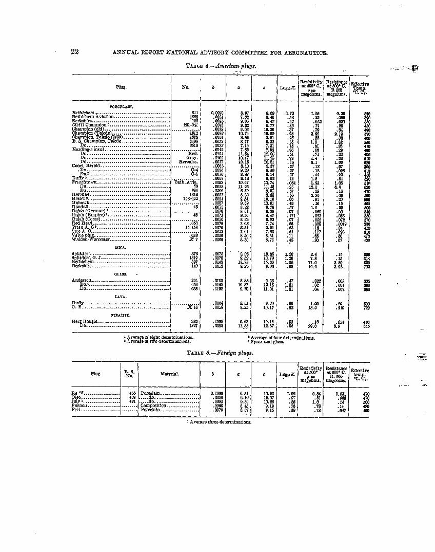
Tables 4 and 5 contain the results on &nerican and foreign spark plugs, respectively.Table 6 gives the compositions and firing temperatures (in terms of Orton’s pyrometric
cones) of the various materials listed in Table 1. The various calcines mentioned in this tablearc described in Table 7.
The numerical values in the tables are in each case the average of the results of till thesamples tested of the same material, but in mmny cases only one sample wns tested. t.Tnfor-tunately, the variation in Te obscrvecl in different specimens of what was supposed to be thesame materitil sometimes amounts to as much as JO* C, and this mwiaticm should bu borne inmind in comparing the results on different materials.
It should also be noted that where both cup and plug samples of non~inally the sumc mutu-rial were tested the latter usually showed decidedly lower resistance. Three explanations forthis may be suggested:
First. The material is made up by a somewhat different process, the cup specimens beingmokled under slight pressure while the pIugs are extruded through a die.
Second. Ehmface leakage and conduction through the glaze may have been present in theplug specimens and not in the cups.
Third. The cup specimens being especially prepared for test, nmy have been made up withgreater care than the plugs.
CONCLUSIONS.
The following conclusions seem evident from the data giwm in the tddes.Quartz is by far the best of the materials tested as far m resistance at h~gh tcmperat.urc is
concerned, although severzl of the laboratory porcelain bodies, such m 77 and 7S, Lppmach thisfairly closely. The mica plugs show fairly high resist.ivity, but i t shoukl he noted also that thismaterial loses its water of crysta”flization at temperatures approaching 1,000° C. and becomesvery soft and friable.
Several of the porcelains recently developed in this country for aviation wdi me wrynotably superior to the majority of the porcelains tested. ‘
The steatite and Rajah porcelains from Ger~ny are not notukdy high in resistivity, andtherefore the very high reputation M spark plug insulnt ors which these materials had before thowar was apparently not due to their resistivity. The French porcelains are on the whole not tisgood as the more recent &nerican bodies. This may account for the preference: fur micti plugsshown in the former country.

PROPERTIES AND PREPARATION OF CERAMI(I INSULATORS FOR SPARK PLUGS.
TABLE I.—Bureau of Standards cups.
21
cup iYo.— ~ b.I
16. . . . . . . . . . . . . . . . . . . . . . . . . . . . . . . ... . . . . . . . . . . I O:m:;~..: . . . . . . . . . . . . . . . . . . . . . . . . . . . . . . . . . . . . . . ..l
. . . . . . . . . . . . . . . . .. . . . . . . . . . . . . . . . . . . . . . . . . .007022. . . . . . . . . . . . . . . . . . . . . . . . . . . . . . . . . . . . . . . . . ..[ .008923. . . . . . . . . . . . . . . . . . . . . . . . . . . . . . . . . . . . . . . . . ..[ .009624. . . . . . . . . . . . . . . . . . . . . . . . . . . . . . . . . . . . . . . . . . . .003525. . . . . . . . . . . . . . . . . . . . . . . . . . . . . . . . . . . . . . . . . . . . 00s5321 . . . . . . . . . . . . . . . . . . . . . . . . . . . . . . . . . . . . . . . ...’ .006435. . . . . . . . . . . . . . . . . . . . . . . . . . . . . . . . . . . . . . . . . . .36...
.0108. . . . . . . . . . . . . . . . . . . . . . . . . . . . . . . . . . . . . . . . .0109
39. . . . . . . . . . . . . . . . . . . . . . . . . . . . . . . . . . . . . . . . . . . .012540. . . . . . . . . . . . . . . . . . . . . . . . . . . . . . . . . . . . . . . . . . . . 00s0471 . . . . . . . . . . . . . . . . . . . . . . . . . . . . . . . . . . . . . . . . . . .009148... . . . . . . . . . . . . . . . . . . . . . . . . . . . . . . . . . . . . . . . . ,010549. . . . . . . . . . . . . . . . . . . . . . . . . . . . . . . . . . . . . . . . . . . .007650. . . . . . . . . . . . . . . . . . . . . . . . . . . . . . . . . . . . . . . . . . . . 011s55. . . . . . . . . . . . . . . . . . . . . . . . . . . . . . . . . . . . . . . . . . . .011963. . . . . . . . . . . . . . . . . . . . . . . . . . . . . . . . . . . . . . . . . . . .009070. . . . . . . . . . . . . . . . . . . . . . . . . . . . . . . . . . . . . . . . . . . .0097721 . . . . . . . . . . . . . . . . . . . . . . . . . . . . . . . . . . . . . . . . . . .009873. . . . . . . . . . . . . . . . . . . . . . . . . . . . . . . . . . . . . . . . . . . .0031741 . . . . . . . . . . . . . . . . . . . . . . . . . . . . . . . . . . . . . . . . . . .00997’7. . . . . . . . . . . . . . . . . . . . . . . . . . . . . . . . . . . . . . . . . . . .006578. . . . . . . . . . . . . . . . . . . . . . . . . . . . . . . . . . . . . . . . . . .;::.: . . . . . . . . . . . . . . . . . . . . . . . . . . . . . . . . . . . . . . . “;gil;
. . . . . . . . . . . . . . . . . . . . . . . . . . . . . . . . . . . . . . . . .941 . . . . . . . . . . . . . . . . . . . . . . . . . . . . . . . . . . . . . . . . . . .0119952......., . . . . . . . . . . . . . . . . . . . . . . . . . . . . . . . . . . ..0089107. . . . . . . . . . . . . . . . . . . . . . . . . . . . . . . . . . . . . . . . . . .0083109. . . . . . . . . . . . . . . . . . . . . . . . . . . . . . . . . . . . . . . . . . .0069116 . . . . . . . . . . . . . . . . . . . . . . . . . . . . . . . . . . . . . . . ...! . 007;
. . . . . . . . . . . . . . . . . . . . . . . . . . . . . . . . . . . . ..j.j ; i%
119. . . . . . . . . . . . . . . . . . . . . . . . . . . . . . . . . . . . . . . . . .1523... . . . .130.
c.
-1S.589.50
‘“ ;:
10:so9.27::$
Ii 0210.3410.849. 2s9,62
1] g2
10:4310.7710.3510,4610.899.64
12.3711.1711.2111.1111.3$13.3211.589.96
10.1811.1811.5111.0310.77
RJzisfevi.ty
P 500megohms.
6. S.11.39.08.32.10.062.14.42. 07s;::9
.12
.10
.19,060.066
2.2.41.40.39
26
H13
2:13
.655.4
~3
;:12
Effeotiretem “c.
$;.
I Average two determinations. ~Avere.geflvedetcrminations. a A~erage three determinations.
TABLE 2.—Cupsfrom manujacturera.
I Maker. ‘No.
Jeffer.,- Dewitt . . . . . . . . . . . . . . . .Jeffery l?f---’”Jefiery Dt~mmp~on ~.gm~!on!
I rer‘PreIFreIFretFreI?herlka[FrexFrel~ex
2Uybl . . . . . . . . . . . . . . ..j 3
eylt~y: . . . . . . . . . . . . ..l1?
(i-mm lonlgnmon~ :::::::::l$~erol . . . . . . . . . . . . . . . . . . . . . . . . 4iiA
lchtown . . . . . . . . . . . . . . . . . . . 577mhtown . . . . . . . . . . . . . . . . . . . 315whtown. . . . . . . . . . . . . . . . . . . 280Iohtown. . . . . . . . . . . . . . . . . . . 776.]chtowm. . . . . . . . . . . . . . . . . . . 7%Xichtown . . . . . . . . . . . . . . . . . . . 7i5B GIchtown . . . . . . . . . . . . . . . . . . . 28BGlchtown . . . . . . . . . . . . . . . . . . . 783]chtown . . . . . . . . . . . . . . . . . . . 741lchtown . . . . . . . . . . . . . . . . . . .
mud. . ... . . . . . . . . . . . . . . . . . . . . 131 Brunt. . . . . . . . . . . . . . . . . . . . . . . . . 154
‘:% i $; #!u J.0083 I 11,11.0075
62010.57 :: :
.0092610
9.65 .11 [email protected] j 10.24 2.8 I.0114
560
I10,12 .020 I
.0107S60
9.74 .025.0080
360
.0080 \11,10 I11,14
.0034 10.76 ‘;6 I %
.0087 10.10 :56 , 470
.0090 10.20 .50 I 470
:gf ~ ljg ~;610590550
.0097 ~ 11:81 9:1 , 600
.
.
Jeffery Dewitt (supply Champion Toleio pings).Titan plugs).
Frenchtown (supply Bethlehem and other plugs). Champion Tgnition Co. (snpply A.C.
TABLE 3. —iWiscdlaneous specimens.
,.R&iistmy
kfateriel. b.
“1 ~
Effectlrec.
P 600tery;“c.
megohme,
‘ Fueclay . . . . . . . . . . . . . . . . . . . . . . . . . . . . . . . . . . .PyrexorucibIe . . . . . . . . . . . . . . . . . . . . . . . . . . . . .Pyrex lssstube . . . . . . . . . . . . . . . . . . . . . . . . . . .
fSodagazs . . . . . . . . . . . . . . . . . . . . . . . . . . . . . . . . . .Quartz. . . . . . . . . . . . . . . . . . . . . . . . . . . . . . . . . . . . .Le.r equsrtz tute . . . . . . . . . . . . . . . . . . . . . . . . . .
\SmalquarW, tribe . . . . . . . . . . . . . . . . . . . . . . . . .
0,00s1.0094.0092.0214.0065.0049.03s4 !
I
10.439.569.14
13.5H. 710.28 I3.36 ~
2.4.072,035. 00+363
2j& o
4.5
22 ANNUAL REPORT NATIONAL ADVISoRy cf)hlMITTEE FoR AERojiJAuT1cs.
TABLE 4.—An3er&xzrI plugs.
IPlug.
lNO”:b
l!I
PORCELAIN. I
Be fhlehenr- . . . . . . . . . . . . . . . . . . . . . . . . . . . . . . . . . . . 611 ;Bethlehem Avkdlon. . . . . . . . . . . . . . . . . . . . . . . . . . . 1668T3rrkshire. . . . . . . . . . . . . . . . . . . . . . . . . . . . . . . . . . . . . . . 128:(3141)Chom ion . . . . . . . . . . . . . . . . . . . . . . . . . . . . . .
!221441
Ghamplon (od) . . . . . . . . . . . . . . . . . . . . . . . . . . . . . . . . . . . . . . . . . . . ...1Champion (Toledo) . . . . . . . . . . . . . . . . . . . . . . . . . . . . . 1812 ICIuwu ion, Toledo (3430). . . . . . . . . . . . . . . . . . . . ..-B. Sti*piorr, ‘I!oledo. . . . . . . . . . . . . . . . . . . . . . . .
18233466
. . . . . . . . . . . . . . . . . . . . . . . . . . . . . . . . . . . . . . . .Hard$g’smsul . . . . . . . . . . . . . . . . . . . . . . . . . . . . . . . . . . . . . . ...!?!!.
. . . . . . . . . . . . . . . . . . . . . . . . . . . . . . . . . . . . . . . . .
%::::::::::::::::::::::::::::::::::::::::Gray:
Hercules.Cyn&Rerold . . . . . . . . . . . . . . . . . . . . . . . . . . . . . . . . . . . . . . . . . ...=
. . . . . . . . . . . . . . . . . . . . . . . . . . . . . . . . . . . . . . . . .~~.2 . . . . . . . . . . . . . . . . . . . . . . . . . . . . . . . . . . . . . . . .
Duffy ‘Z. .C-3
. . . . . . . . . . . . . . . . . . . . . . . . . . . . . . . . . . . . . . . . . . . . . . . . . . . . .l?rcn~gt~wn . . . . . . . . . . . . . . . . . . . . . . . . . . . . . . . . . . . . Beih. A~-fa.
. . . . . . . . . . . . . . . . . . . . . . . . . . . . . . . . . . . . . . . . 56no. . . . . . . . . . . . . . . . . . . . . . . . . . . . . . ... . . . . . . . . .
Hercules . . . . . . . . . . . . . . . . . . . . . . . . . . . . . . . . . . . . . . . 1%Wxdcrz.. . . . . . . . . . . . . . . . . . . . . . . . . . . . . . . . . . . . . . . 79WM3Mohnwk . . . . . . . . ..- . . . . . . . . . . . . . . . . . . . . . . . . . . . . . . . . . . . . . . . . . .Rondstl . . . . . . . . . . . . . . . . . . . . . . . . . . . . . . . . . . . . . . . .Ra]ah ({:erman)z . . . . . . . . . . . . . . . . . . . . . . . . . . . . . . . . . . . . . . ...!.l@h(Empire)z.. . . . . . . . . . . . . . . . . . . . . . . . . . . . .TW@(Coors). . . . . . . . . . . . . . . . . . . . . . . . . . . . . . . . . . . . . . . . . . ...!!T@dHead.. . . . . . . . . . . . . . . . . . . . . . . . . . . . . . . . . . ..- .656T1tsu A. C~. . . . . . . . . . . . . . . . . . . . . . . . . . . . . . . . . . . . 15.43RC3COA.C. . . . . . . . . . . . . . . . . . . . . . . . . . . . . . . . . . . . . . . . . . . . . . . . . . . .Valve plug . . . . . . . . . . . . . . . . . . . . . . . . . . . . . . . . . . . . . . 02slV81don-11’0rc* tcr. . . . . . . . . . . . . . . . . . . . . . . . . . . . . . X7
MICA .
SpTitdorf. . . . . . . . . . . . . . . . . . . . . . . . . . . . . . . . . . . . . . .Splitrlorf, G. J. . . . . . . . . . . . . . . . . . . . . . . . . . . . . . . . . / 1;)T4ethlchem. . . . . . . . . . . . . . . . . . . . . . . . . . . . . . . . . . . . .Berkshire . . . . . . . . . . . . . . . . . . . . . . . . . . . . . . . . . . . . . . . 110
GLASS. . IAnd;~4n . . . . . . . . . . . . . . . . . . . . . . . . . . . . . . . . . . . . ...” 20:
. . . . . . . . . . . . . . . . . . . . . . . . . . . . . . . . . . . . . . . . . WIDo . . . . . . . . . . . . . . . . . . . . . . . . . . . . . . . . . . . . . . . ..i 655
LAVA.
Duffy . . . . . . . . . . . . . . . . . . . . . . . . . . . . . . . . . . . . . . . . . . .. . . . . . . . . . . . .G. E . . . . . . . . . . . . . . . . . . . . . . . . . . . . . . . . . . . . . . . . . . . . X 16
STEATITE. I
Her~~ougic . . . . . . . . . . . . . . . . . . . . . . . . ..’ . . . . . . . ..l 332. . . . . . . . . . . . . . . . . . . . . . . . . . . . . . . . . . . . . . . . . 1 1327
. Ce378
.0378
.0143
. 0W3
.Om
.0156
. oUa
.Ootx
.(s)33
.0098
.(M2S
j Average of eight determinations.~Average of two determinations.
-,-,‘:
a
&519.2s
c
i10.2s ,10.79 ‘l;% t
.,
i9.33
H j
I9.20,
10.17~
IO.16 ;12.37,
f4T10k’
:;;.42
:$?‘.23.25.15.15.36.51.78.66
:$.27,44;~
.57
:;
. SW
.07
.171
:%.G3.61.11.$
L 20
i%.63
.47L 311.31
.69
.92
.53
.54
ysti:g
me&%e
L 36.22.05.74.79
3.99. 5s
1.Q.51.Cd
1:P9.1.13. 1s.44
&12.0
+
.461.0.IM,0%.06.00!.18. Iu.63.!22
%!71.019.0
. ox
.02
.04
&?
.1829.0
TABLE ii.-poreig?zp~eqa.
*A\.erageoffmrr determination,4Pyresondglsss.
Mktanhat W“ C.
RW3ncgohms
0,36X4,20,84
%19.32
1:~
.29
.22
.231.00
: Es
.54L 056.8.16. 6!3
:$
:&l.050.072. cm.01
:%’.07
.::.!
:%
.(M3
.001
. C(I2
: Ro
.054&5
MwtkeTcrrrw.&
5303mWI
i%’670469
E400
:K624
%%’‘g
510&xl470
1%466
g
37n
?0310470m
S30G14GKI70Q
333
:2
WI7XT
4m635
—-.=. ..= .

—.
!$i’rliti
.
1617
:
%;;
::40474s49505“,0
$
%74777879689:
1%109116119152180
P, ct. P. ct.11.25 112511.25 11.2511.25 11.251125 11,2511.25 11.2512.50 12,5012.50 12.5013.7.5 13.7513.75 13.7513.75 13.7513.75 13.7515.00 15,0015.00 15.0012.50 12.5012,50 12.5012.75 12.751250 12.5012.50 12.5012.50 12.509.00 :. g9.00 .
. . . . . . . . . . . .1.25 1.252. !50 2.502.50 2.50
12.50 12.5011.25 H. 2510.00 10.001:.:3 13.50
12:50 .ii~ii12.50 12.507.50 7.506.87 27.75
—
.AND PREPARATION OF CERAMIC INSULATORS FOR SPARK PLUGS. 23
TABLE 6.—Spark plug compositions.
P. ct. P. ct.16.00 39.0018.00 370020.00 35 m28.00 27.0030.00 %.0016.00 3’4.0024.(jO 26.0014.50 29.0020.50 23.0022.50 21.0028.50 15.0016.00 24.0030.00 10.0024.00 5.0022.co 12.00;~~ . . . . . .
13:50 ‘::::::16.4022.00:::::::17,60 . . . . . ................. ...’.... . .. . . . ..1....... ..... .. ....8.00 I 30.00
17.60 :....... . . . ..’ 42.0014.00 ; 21.lM. . . . . . . . . . . .. . . . ..i 30.00. . . . . . . 30.00... ...1.. . . . .
“-”...1575
P. ct.. . . . .. . . . .. . . . .. . . . .. . . . .. . . . .. . . . .1.501.501.501.50
. . . . .
. . . . .1.001.00L 501.501.501.00
. . . . .
. . . . .
. . . . .
. . . . .
. . . . .
. . . . .
. . . . .
. . . . .rgco10.00. . . . .. . . . .. . . . .rfc5;
— —P. ct. P. ct.. . . . . . . . . . . .. . . . . . . . . . . .. . . . . . . . . . . .. . . . . . . . . . . .. . . . . . . . . . . .. . . . . . . . . . . .. . . . . . . . . . . .. . . . . . . . . . . .. . . . . . . . . . . .. . . . . . . . . . . .. . . . . . . . . . . .. . . . . . . . . . . .. . . . . . . . . . . .. . . . . . . . . . . .. . . . . . . . . . . .. . . . . . . . . . . .. . . . . . . . ...”.. . . . . . . . . . . ....... .. ....5.00......5.00 . . . . . .7.50 7.505.00 5.005.00 5.007.50 7.50
I...................................4.00 4.00
10.00 10.00. . . . . . . . . . . .. . . . . . . . . . . .;% 5.@l
4.53
P. ct.. . . . . .. . . . . .. . . . . .. . . . . .. . . . . .. . . . . .. . . . . .. . . . . .. . . . . .. . . . . .. . . . . .. . . . . .. . . . . .20.03
. . . . . .
. . . . . .
. . . . . .
. . . . . .
. . . . . .
. . . . . .
. . . . . .
. . . . . .
. . . . . .
. . . . . .
. . . . . .
. . . . . .
. . . . . .
. . . . . .M&g
. . . . . .
. . . . . .
. . . . . .
. . . . . .-
P. ct.. . . . . .. . ...<. . . . .. . . . . .. . . . .. . . . .. . . . . .. . . . .. . . . . .. . ...!. . . . . .. . . . . .. . . . . .. . . . . .. . ...<. . . . . .20.0015.oil. . . . . .. . ...!. . . . . .. . . . . .. . . . . .. . . . . .,. ...,,. ...,,. ...,. . . . . .. . . . . .15.00. . . . . .,. ...,,. ...,. . . . . .
~
ig
8—>.ct.,.. .. . . .. . . .).. .. . . .. . . .. . . .. . . .,.. .,.. .,.. .,. .... . . .,.. .,.. .,.. .,.. .,.. .L 10.. . .L40,.. .,. ...,. ...,.. .,. ...,. ...,. :.,,. ...,. ...,. ...,. ...,. ...,. ...
C4.
i
j
6—~.et.....:. .... ... ..... ... ..... .... ... ..... ... ...... ........ .... .2.50.. . ... . .1.50.. . ... . ... . ... . ... . ... . ... . ... . .,.. ... . .,.. ... . ... . .).00.. . .
I
I
— .P. Ct. P. ct.. . . . . . . . . . .. . . . . . . . . . .. . . . . . . . . . .. . . . . . . . . . .. . . . . . . . . . .. . . . . . . . . . .. . . . . . . . . . .. . . . . . . . . . .. . . . . . . . . . .. . . . . . . . . .. . . . . . . . .. . . . . . . . . . .. . . . . . . . . . .. . . . . . . . . . .. . . . . . . . . . .. . . . . . . . . . .. . . . . . . . . . .. . . . . . . . . . .. . . . . . . . . . .. . . . . . . . . . .. . . . . . . . . . .35.00 . . . . .i5. 00 . . . . .30.03 . . . . .75.oil . . . .. . . . . . 12.00. . . . . . 4.40. . . . . . . . . . ....... ........... ........... 20.00. . . . . . . . . . .. . . . . . . . . . .. . . . . . . . . . .
. —P. ct. P. ct.. . . . . . . . . ...!. . . . . . . . . . . . .. . . . . . . . . . . . .. . . . . . . . . . . . .. . . . . . . . . . . .. . . . . . . . . . . .. . . . . . . . . . . .. . . . . . . . . . . .. . . . . . . . . . . .. . . . . . . . . . . .. . . . . . . . . . . . .. . . . . . . . . . . . .. . . . . . . . . . . .. . . . . . . . . . . . .. . . . . . . . . . . .. . . . . . . . . . . . .. . . . . . . . . . . . .. . . . . . . . . . . . ....... ............. ::;;...... ........ ............. ............ ............. ............ :JKJ. . . . . . .13.00 ,. . . . . . .
t...... ........ ..... ............. .......D3.00 .......20.00Al,Os. . . . . . 11.52
TABLE 7.—S’park plug hines.——
1 CaloiningB. of S. caldne, No. hrgco~. Kaolin. Mrlt. ~~,;: Boric acid, te~u;~
Pe&caJ. P;oy;t. Per cent. Per cent. Per cwt. C;te.3 . . . . . . . . . . . . . . . . . . . . . . . . . .8A . . . . . . . . . . . . . . . . . . . . . . . .
. . . . . . . . . . . . . . . . . . . . . . . . . . . . . . . . . . . .14:40 44.30 41.30 . . . . . . . . . . . . . . . . . . . . . . . .23.85 76.15 . . . . . . . . . . . . . . . . . . . . . . . . . . . . . . . . . . . . ;:
ii:::::::::::::::::::::::::: 13.20 56.m 25.60 13. . . . . . . . . . . . 70.20 . . ..ii.ii... -“.. Kiil--- “.--i:if... 20
;::::::::::::::::::::::::::: 34.30 . . . . . . . . . . . . . . . . . . . . . . . . . . . . . . . . . . . . . 16
16down.15down.14down.14half over.13half over.15down,14hal$ver,
12dm#.
[3 d:w”i.10down.i4 d~on.
Do:14half over.[6 down.~4down.13d~on.
%:Do.Do.
.5 half overMdown.10down.[2 down..6 down..8 do&n.
.6 dowi!0down.
.

REPORT NO. 53.PART ~.
PREPARATION AND COi%lPOSITION OF CERANIICINSULATORS.’
By A. V. BLEININGER.
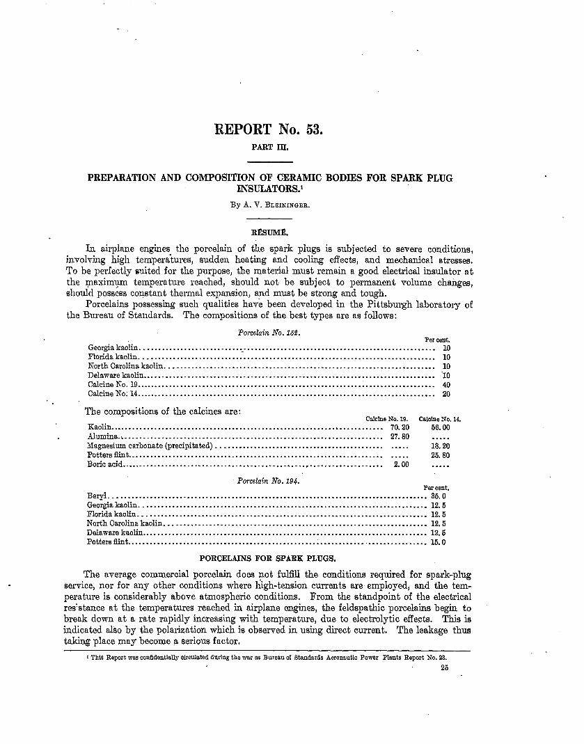
R~SUM~.
In airplane engines the porcelain of the spark plugs
BODIES FOR SPARK PLUG
is subjected to severe conditions,involving high temperatures, sudden heating and cooling effects, and mechanical stresses.To be perfectly suited for the purpose, the material must remain a good electrical insulator atthe yaximqm temperature reached, should not be subject to permanent volume chaiges,shoulcl possess coqstant thermal expansion, a?ld must be strong and tough.
Porcelains possessing such qualities have been developed in the Pittsburgh laboratory ofthe Bureau of Standards. The compositions of the best types me as follows:
Porcelain No. 16.??.Per cent,
Georgia kaolin . . . . . . . . . . . . . . . . . . . . . . . . . . . .. . . . . . . . . . . . . . . . . . . . . . . . . . . . . . . . . . . . . . . . . . . . . . . . . . . . . 10Flotida kaolin . . . . . . . . . . . . . . . . . . . . . . . . . . . . . . . . . . . . . . . . . . . . . . . . . . . . . . . . . . . . . . . . . . . . . . . . . . . . . . . . 10
'OrthcarO1ina v::.:::::::::::::::::::::::::::::::::::::::::::::::::::::::::::::::::::::::: :Delaware kaolinCalcite No. 19. . . . . . . . . . . . . . . . . . . . . . . . . . . . . . . . . . . . . . . . . . . . . . . . . . . . . . . . . . . . . . . . . . . . . . . . . . . . . . . . . 40Calcine No; 14. . . . . . . . . . . . . . . . . . . . . . . . . . . . . . . . . . . . . . . . . . . . . . . . . . . . . . . . . . . . . . . . . . . . . . . . . . . . . . . . . 20
The compositions of the calcines are:Calcine No. 19. Calcine No. 14.
Kaolin . . . . . . . . . . . . . . . . . . . . . . . . . . . . . . . . . . . . . . . . . . . . . . . . . . . . . . . . . . . . . . . . . . . . . . . . . . 70.20 56.00
Alumina.: . . . . . . . . . . . . . . . . . . . . . . . . . . . . . . . . . . . . . . . . . . . . . . . . . . . . . . . . . . . . . . . . . . . . . . 27.80 . . . . .
hIagnesim carbonate (precipitated) . . . . . . . . . . . . . . . . . . . . . . . . . . . . . . . . . . . . . . . . . . . . . 18.20
Potter6fint . . . . . . . . . . . . . . . . . . . . . . . . . . . . . . . . . . . . . . . . . . . . . . . . . . . . . . . . . . . . . . . . . . . . . . . . . .
. . . . .
26.80
Boric acid . . . . . . . . . . . . . . . . . . . . . . . . . . . . . . . . . . . . . . . . . . . . . . . . . . . . . . . . . . . . . . . . . . . . . . . 2.00 . . . . .
Porcelain No. 194.Per cent.
Beryl . . . . . . . . . . . . . . . . . . . . . . . . . . . . . . . . . . . . . . . . . . . . . . . . . . . . . . . . . . . . . . . . . . . . . . . . . . . . . . . . . . . . . . 35.0Geor@akaolin . . . . . . . . . . . . . . . . . . . . . . . . . . . . . . . . . . . . . . . . . . . . . . . . . . . . . . . . . . . . . . . . . . . . . . . . . . . . . . 12.5Florida kaolin. . . . . . . . . . . . . . . . . . . . . . . . . . . . . . . . . . . . . . . . . . . . . . . . . . . . . . . . . . . . . . . . . . . . . . . . . . . . . . 12.5North Carolina kaolin . . . . . . . . . . . . . . . . . . . . . . . . . . . . . . . . . . . . . . . . . . . . . . . . . . . . . . . . . . . . . . . . . . . . . . . 12.5Delaware kaolin . . . . . . . . . . . . . . . . . . . . . . . . . . . . . . . . . . . . . . . . . . . . . . . . . . . . . . . . . . . . . . . . . . . . . . . . . . . . . 12.5Potters flint . . . . . . . . . . . . . . . . . . . . . . . . . . . . . . . . . . . . . . . . . . . . . . . . . . . . . . . . . . . . . . . . . . . . . . . . . . . . . . . . 15,0
PORCELAINSFOR SPARK PLUGS.
The average commercial porcelain does not fulflll the co~ditions required for spark-plugservice, nor for any other conditions where high-tension currents are employed, and the tem-perature is considerably above atmospheric conditions. From the standpoint of the electricalresistance at the temperatures reached in airplane engines, the feldspathic porcelains begin tobreak down at a rate rapidly increasing with temperature, due to electrolytic effects. This isindicated also by the polarization which is observed in using direct current. The leakage thustaking place may become a serious factor.
1This Report was confidentially circulated during the war as Bureau of Standards Aeronautic Power Plants Report No, 23.
25

26 ANIWJAL REPORT NATIONAL ADVISORY COMMITTEE FOR AERONAUTICS,
This wrerage porcelain k ~ikewke not constant h vohme; and these volumetric changestire greater than can be explained solely by thermal expansion. .Asicle from the thermtilexptinsion? the quartz content. of porcelain, when heated or cooled, is subject to certtiin modi-fications in crystalline structure, accompaniecl by definite vohune changes. Thus, the f(]rnlof quartz permanent at atmospheric temperature is alpha quartz, which inverts t.o beta quartzat 5700 C, a transformation which is reversed by cooling. C)n the other hand if, in the firingof porcelain, the quartz is inverted to its high temperature form, cristobditc, them is againthe transformation of the alpha to the beta modification to be considerecl, which t.dws phiceat 220° C. In either case, -rolume changes are unavoidable in alI porcehtins containing freoquarti~ in large amounts, due to the inversion noted. In a goocl spark-ph~g porcelain, thequartz shoukl be eliminated from the compound and replaced by a subst ante not subject tothese inversions.
,
Another dcfec.t of the ordinary porcehiin is that the coefficient of thmmd expansion isby no means constant at clifferent temperatures, It mtiy be 19 x 10-’ between 30=-200° Cand 5 x 10⁴ between 400—5000 C.
With respect to mechanical strength, also, great variations are p&sible. ii series of testsof commercial electrical porcelfiins, conducted at the Pittsburgh labornt.ory of the Bureau ofstandards, showed differences in the modulus of elasticity varying from 1,600,000 to 6,000,000.
J?or the purpose of studying porce18ins from the standpoint of their electrical conduc-tivity at the high temperatures obtaining ~ airplcne ignition systems, a large number oftypical compositions were made Up in the form of the test CUPSilhmtrated in figure 2 of Ptut11 of this report. These mixtures were usually prepared in 10-kilogram batches, carefullyweighed out and ground wet, in porccla,in-lined ball milk for three hours. The- suspmsicm ofclay was pumped into a Hlter press to remove the water! and then kneaded in a mixing mathincto tlm conshtcwcy required for shaping the mass on the potters wheel. This wtis done by theuse of phwter molds in which the cups were “ jiggered “ in the usual mtinner in which potteryis made. The specimens were then dried, placed in fire-clay containers (saggers) and burnedin a down-draft kiln tied -with natmal gas to the finishing temperature. The la.tte.r wus con-trolled both by means of thermocouples with the necessmy ga.lwmometers, and pyrometriccones, made by Edward Orton, Columbus, Ohio. Each cup w-us examinecl for nontibsorpt.ionby the application of ink. The testing of the specimens was done at the Washington labora-tory as described in Part II of this report. The char~cteristic expression for the rcs:stivityof the porcelains is the T~due which represents the temperature in “C. tit which a cubiccentimeter of the material still shows a resistance of one megohm.
REPLACEMENT OF FELDSPAR.
tTpon comparing the T,values of the diflerent porcelains it was noted that there existsno definite relation between the composition and the electrical conductivity. On the otherhand, the higher the maturing temperatures of the porcelains, the higher was the T, due.This is practically equivalent to saying that, roughly speak~~, the electrical rcsistmce athigher temperatures is the greater the lower the feldspar content, since small amounts of thisflux make it necessary to carry the porcelain to a higher burning temperature. TIN rcintion,however, is not well defined, as maybe observed from the resuhs compiled in the fohving tuble:
TABLE 1.

PROPERTIES AND PREPARATION Ol? CERAMIC INSULATORS .FOR SPARK PLUGS. 27
It is qui e evident that the micro-structure of the porcelains is an important factor in this\
.conru.wtion, since it can not be. immaterial how m“uch kaolin or quartz has been dissolved bythe fused felds~ar and “how much sillimanite has been formed. The evidence, however, wasconsidered sufficient to warrant the replacement of the feldspars by other fluxes, the oxides ofmagnesium and beryllium being used for this purpose.
Owing to the evolution of carbon. diofide during the firing process from magnesite, andthe artificially prepared basic magnesium carbonate, and the very large shrinkage accom-panying their use as a flux, it was decided to introduce the magnesia in the form of a calci.ne;that is, a silicate mixture previously fired to a point close to vitrification. The mixtures em-ployed for this purpose correspond to the formula: MgO Al,O, 2Si0,; MgO AI,08 4Eii0,, and”MgO Al,O, 6SiOz. Of these, the first and the second were most used in this work. The prepar-ation of the calcines consisted in dry ball mill grinding and firing the mixture made up intoballs with just sufficient water. After calcination, the materi~ was crushed and ground and”introduced into the bodies in this form. The beryllium oxide was brought in through the useof the mineral beryl (which has the general composition 3Be0 AlzO~ 6SiOJ without any previoustreatment.
With the use of ma~-esia ““as”the principal. flux; “the electrical resistance and hence thevalue Z’ejwas found to increase quite decidedly, though with no well-clefhed regularity as referredto percentage content of magnesia. It was seen again in this connection, that the structure ofthe porcelain plays an important part especially as it is known that JIgO accelerates the crys-tallization of sillimanite most vigorously. Not only the number but also the size of the silli-..manite crystals is of significance. in determining the texture of the body, whether it. is to be finegrained, glassy, or coarsely crystalline. The rate “ofcoolhg the-porcelain is likewise of import-ance, since a rapid drop in temperature invariably causes the structure to b-e.closer and of morevitreous character than when a longer time is taken in cooling down the” kiln. For this reasonsmaller kdns are to .be preferred to larger ones, since they require less time in cooling at agiven rate. The effect of magnesia added in the form of synthetic silicate, is strikingly shownby the high T, values of bodies JXos. 77 and 78. See Table .IV.
It is a fa~t that the magnesium silicates show electrolytic effects .w~ch are .rnuch less-prominent than when feldspar, an alkali-aluminum silicate (K,O Al,08 6~i0,) is used as a flu”:It like-wise appears that the higher the firing temperature of the porcelain the greater its elec-trical resistance, at temperatures up to 700” C., or somewhat abo-ie this point.
With reference to the use of beryllium oxide it was found that this flux behaves sti”ilarlyto the magnesia in showing high electrical resistance and T, values. This is indicated by thefollowing table:
TABLE 11.
I ! I I i-l I 1’
I I I 1 I. . ..- ,.
,
.-.: ._
-- .—
.-
.-
-.
-. —
. . . .
.
It is evident from these results that beryllium oxide, used in the form of the mineral beryl,is a valuable flux from the standpoint here ur@er consideration. It requires, however, carefultemperature control in firing, since the beryllmm porcelain is subject to “sudden deformationas the vitrification temperature is exceeded. The experiments. have prov& that beryllium” ~oxide is worthy of consideration for the production of”such porcelain, and the high Tt valueobtained, 798, is exceedingly promising. T@ firing tetiperature of these bodies is “quite low,from cones 11-12.
Another interesting fact developed with reference to the thermal. expansion of the beryl-Iium porcelain, which was found to be lower than that of the feldspathic bodies commonlyemployed. The average coefficie@ was found to be 1,63X 10-’ for the temperature interval26—200° C.; 2.95 x 1“0–8for 200—400°; 3.60x 10–0 for 400-570°; aid 2.33x 10–Efor 26—400°. -
—---

28 ANNUAL REPORT NATIONAL ADVISORY CO.M.MITTEE FOR AERONAUTICS.-—...-
REPLACEMENTOF QUARTZ.
From ageni$rai study of porcelains, it appears desirable to eliminate the qufit.z, as has beenpointed out in a previous paragraph. Some of the materials available for this purpose arecalcined kaolin, synthetically prepared sillimanite (&O~ SiOz), and sinterccl or fused aluminaand zirconium oxide. These substances have been introduced in a number of compositions.The effecti adding calcined kaolin in general was beneficial; and even with a fcldspw contoutof 13.5 per cent (body No. 63), a fair T“ value, 540, was. obtained. This ptirt.icular compositioncontained 50 per centi raw kaolin, 13.5 per cent feldspar, 1.5 per cent=wdcium carbonate, and35 per cent calcined kaolin. The maturing temperature of this porcelain was thut correspond-ing to cone No. 16. It k evident that by raising the content of ca.lcined kaolin still mom atthe expense of the feldspar a higher T, value would ba obtained. The introduciicm of plasticball clay to replace kaolin, invariably and in aIl types of bodies, reduces the electrical resistancewithin the temperature range here under consideration.
The use of fused alumina in any extensive work was prohibited by tho lack of material lowin iron content. The commercial substance (a.hmdum) is unsuited for this purpose. The totalamount of white fused alumina available was not more than 2 pounds. To bring about thenecessary impervious and dense structure the use of 17.6 per cent-f feldspar was required. Amixture consisting of 45 per cent kaolin, 17.6 per ceg-t feldspar, 4.4 pm cent calcine No. 13,and 33 per cent of alundum, resulted in a very tough porcelain which showed a T~ value of 620.Calcine No. 13 was compounded according to the formula kfg(l ~1,0, 2SiOa from 84 parLs, byweight, of magnesium carbonate and 258 of pkwtic kaolin from Florida and Georgia. Hereagain the reduction of the feldspar content and its replacement by calcino INo. 13, or beryl, ora combination of these two would be certain to raise the T~value considerably ml at the snmetime would result in a porcelain of excellent mechanical properties. The cost of tho fusedwhite alumina would be quite high, but would be justi.tkd under tho circumstances. - Further-more, a single calcine could be readily produced by combining the raw materials of calcincNo. 13, the kaolin and magnesite, with uncalcined ahunina from any corrvcnient source, andfiring the mixture to a point of constant volume, which_ could be accomplished at ~emperaturmnot exceeding cone .Nn. 18. At the same time this procedure. would simplify the process ofpreparation very considerably.
Sillimanite (AlzO&iOJ is a normal component of all hard fired porcelain; and this con-stituent, if not present in the form of. large crystals, imparts to the mat trial const tincy involume upon heating, lowers the thermal expansion, increases the refractoriness, and the resist-ance to sudden heating and cooling. For this reason it was thought desirable to producethe mineral synthetically and to introduce it in the porcelain composition in place of thequartz. This was done by combining 7Q.20 per cent=of pl@ic kaolin, 27.80 of anbydrousalumina, and 2 per cent of boric acid. After grinding this mixture in the dry state in a ball mill,it was made up with watxw to form a plastic mass which was molded into balls calcincd to utemperature corresponding to that of cone No. 20, or appro~imately 1,530° C. At this teKn-perature the mass sintered to a dense structure, subject to but little additional shrinkagetmd containing only a small amount of uncombined alumina. The boric acid was addctl toassist-in bringing about the necessary shrinkage and closing up of the pores, rmd it is quiteprobable that most of this constituent is volatilized at the iinal temperature of the calcinntion.This calcine (hTo. 19) was then crushed separately, passed over a magnetic separator, and thenground, together with the other materials of the b6dy with the addition of water} in the ball mill.In preparing this type of body the feldspar was eliminated on the basis of the results cliscussctiabove, and replaced by a calcine corresponding to the formula lfgo AIZO* 4SiOZ (No. 14).This porcelain (No. 152) was composed of 30 per cent of kaolin, 10 per cent of ball clay, 40 percent of sillimanite calcine, and 20 per cent of fluxing calcine No. 14, and fired to a twnpcra turcof cone hTo. 16 or higher. The resultant material had excellent mechanical qualit ics and anaverage Te value of 690. The structure of this body should be fine and dense, a conditionwhich requires quite rapid cooling of the kiln. Slower coding results in the fmwmtion of conrsersillimanite crystals which cause a structure much less resistant to sudden heating and cooling.

PROPERTIES AFfD PREPARATION OF CERAMIC INSULATORS FoR sP~K PLuGs. . 29
The preparation of this body maybe simplified by the combination of the two calcines intoone, thus, by employing the composition of the flux No. 13 “(MgO &O~ 2SiOJ the ‘co’mbinedcalcine would be composed of 75.10 per cent plastic kaolin, 8.77 per cent magnesite, and 16.13per cent anhydrous alumina. The boric Ecid content has been eliminated. Body No. 152would then consist of 30 per cent of kaolin, 10 per cent of ball clay, and 60 per cent of the com-bined calcine. TVherever the working conditions permit the ball clay-should be eliminated,and an effort made to employ the body containing 40 per cent of plastic kaolin, which canusually be done by allowing the mixture to age before mo~d~ng it.
The tendency of the body to crystallize may be dimmlshed also by replacing the fluxingcalcine in part by beryl, so that thdse two components are firesegt in the.ratio of 1;1. If, then,th~ combined fluxing and sillimanite calcine is employed, the resultant composition would bekaolin, 60.94 per cent; anhydrous alumina, 18.39 per cent; boric acid, 1.32 per cent; rna~esite,4,58 per cent; beryl, 14.78 per cent. The body, as before, would consist of 60 per cent of thiscalcine and 40 per cent of kaolin. The fusion point of this mixture is so low that it would bequite possible to eliminate the boric acid entirely. At the same time the vitrification point ofthe body is lower and closer to the normal kiln temperatures.
Attention might be called to the fact that the use of a siliceous porcelain is not objectionablefrom the electrical standpoint but only from consideration of the mechanical strength, resist-ance to sudden temperature changes, etc. This is shown by. the results upon high silica porce-lains, bodies Nos. 116 and 119, which show a very high T, value, namely 730. This type of por-celain contains 50 per cent of clay, 30 per cent of free quartz (flint), and 20 per cent of magnesiacalcine. In No. 116, the calcine- corresponds to the formula MgO AlzO, 2Si0,, and in No. 119to MgO AlzO~4Si0,. It is.fair to state those porcelains would give excellent results, consideredfrom the dielectric standpoint, when used under conditions not so-extreme with reference totemperature and shock as is the case with spark plugs used in airplane engines.
Zirconium oxide was used only in two porcelains, due to the comparatively limited supplyavailable. The material at hand was zircon which contained 52;74 per cent of 2rOZ and 42.46per cent of silica. As received, the mineral was high in iron, which, however, was ‘eliminatedby treatment with chlorine at a temperature of 800° C. In “this manner all but a trace of theiron was removed. Owing to the fact that these zircon porcelains were produced comparativelyearly in the work, feldspar was employed as the flux. The result was that the electrical resist-ance, and hence the T~ value, was low, being 500 and 450, respectively. With the use of the mag-nesia or beryllium fluxes much bettex products could undoubtedly be produced. The mecharvical strength of these porcelains was excellent in every respect... The composition of these bodies,Nos. 72 and 73, is given in Table IV.
. . .
The effect of the quartz in porcelain upon the thermal expansion of the body is shown bythe results compiled ti-Table III.
TABLE III.
.1~+ ““,........j””
Coellloient of thermal expansionxlo!
No. clay. ~$n;z kfgO cal- Formula of MgOeal- ~y~;etine. tine. calcine. 30-%30“e?. Z,&Moo “c. 4CC-550“c. 30-400 “c.
_ -
Pmgrli. Pmg$. Per3;enL Per cent. . Per cent.114 Mgo AI*O*6sios.. . . ... . . . . . . . . . . 1: #116 50 30
9.35 5.52 13.99MgO A1z082SiOz. . . . . . .’. . . . . . . . .
1176.11
n4.68 6.68
afgf) A]@* 2S!09. . . . . . . . . . . . . . . . 8:93119 % ::
4. 4s20
4.”&5 6.51MgO AI*084s10g. . . . . . . . . . . . . . . . 19.61
120 5011.13 8.08
so15.03
MgO AIz084SiOs . . . . . . . ...=...152 40 . ...?.... 20,
1::: 5.43 4.45 7.74MgO Al~Os4S102.. . . . . 4,19 4.78 3.81
,-. .-
-.
.
.
..—.
.“. . ...=--
-. ,
It is at once evident from a comparison of these figures that the thermal expansion of thesemagnesia porcelains incremes with the silica content of the body, and, at the same time, issubject to decided variation within the temperature limits of 30°-5500 C. On the other handthe porcelain in which the clay content is lower, and all the quartz has been replaced by sil.li-manite, shows both the lowest thermal expansion and the least variation in the value of thecoefficient. However, the composition is not the only determining factor, and the importanceof the microstructure must be realized.

30 ANNUAL REPORT NATIONAL ADVISORY COMMITTEE FOR AERONAUTICS.
CONCLUSIONS.
The work, the results of wh@h have been given, has been successful in showing: First, theinjurious qualities imparted to electrical porcelains by the. use.of feldspar as a flux; and second,in bringing out the desirability of replacing the quartz by minerals or synthetically preparedmaterials which are more constant in volume when heated. The remedial procedures advocatedare, hence: (1) The replacement of feldspar by other fluxes, such as silicnt.cw of the typeMgO AI,O~ 2Si0,, or MgO AlaO~ 4S30Z, or other silicates of beryllium and the rdkalinc earths,either natural or prepared artificially. (2) The elimination of quartz and the substi~ution ofsubstances not subject- to inversions or other volume chan~s. These may be highly cmlcinedkaolin, alumina, zircon, or sillimanite, ei~her natural or produced syntheticfly.
The compositions of the most typical porcelains produced in this -work me compihd in.
Tables IV, V, and VI, and the 2’, value is given for eac~~body, so that these tabulations maybeconwdted for detailed information.
All of the electrical measurements, &Swell as the d~t&minations .of the thermal cxpansiin ofthe porcelains, have been made in the Washington laboratories of the Bureau of Standards.
TABLE Iv.
Nomber of body. 16
‘ ‘“ ““ ~‘r -
17 18 32 23 2412332 35 30 39 40— — —. .
Per ct. Pw CL Per d. Per ct. Per c’. Pel ct. Per ct. Per ct., i% d. Per d. Pcr ct. Ptr ct.Kaolin... -. . . ..-- . . . . . . . . . . ..-. -=--------- ;: ~ ?5.00 45.00 45.~ 45.~ ~.~ ~.oo 55.~ 1 55.W s~.w =m 00.~Feldspw 18.00 20.00 23.00 30.00 16.00 24.00 14.50 ~ 20.50 22.50 23.50
‘.-:::::::::::::::::::::::::::::::: 39.00 37.el 3s.@l 27.00 25.co 34.00 26.00 a~g ~ ~.$ 21.00 M.alPotters flint180024.W
Wh’t{ng(CaChJ) . . . . . . . . . . . . . . . . . . . . . . . . . . . . 1. . . . . . . . . . . . . . . . -------- -------- ----::-- . . -------------- . : . . .
. . . . . . . . . . . . . . . . . . . . . . . . . . . . . . . . . . . . . . . . . . . . . . . . . . . . . . . . . . . . . ..--.:. . . . . . . . . . . ... . .Bail (lay. . . . . . . . . . . . . . . . . . . . . . . . . . . . . . . . . . . . . . . . . . . . . . . . . . . . . . ... . . . . . . . . . . . . . . .. a- . . . . . . . . . . . . . . . . . . . . . . . . .. . . . . . . . . . . . . . . . . . . . . . . . . . . . . . . .Cakined kaolin. ._ -,Cakfne No. s...
I. . . . . . . . . . . . . . . . . . . . . . . . . . . . . . . . . . . . . . . .. . . . . . . . . . . . . . . . . . . . . . . . . . . . . . . . . . . . . . . . . . . . . . . . . . . . . . . . . . . . .- .--i:. . . . ... . . . . . . . . . . . . . . . . . . . . . . . . . .. . . . . . . . . . . . . . . . . . . . . . . . .
CaIcine No. 19. . . . . . . . . . . . . . . . . . . . . . . . . . . . . . .. . . . . . . . . . . . . . . . . . . . . . . . . . . . . . . . . . . . . . . . . . . . . . . . . . . .. . . . . . . . . . . . . . . . . . . . . . . . . . . . . . . . . . . . . . . . . . . . .Crdcine No.20 . . . . . . . . . . . . . . . . . . . . . . . . . . . . . . ~... . . . . . -------- -------- -------- ------- ----s--- ---------------- . . . . . ..+ . . . . . . . . . . . . . . . . . . . . . . .
Zh-con.“--. ”-”. --------: --------------------- -“--~g- --q- --”--# ----;#- “----ii’ “-”’:$ ‘-”.~ ‘“--:~”.--.-~~- ‘-..~~ ‘..”~~ ‘... --ii~Y~/u~ temperature m cones . . . . . . . . . . . . .
. . . . . . . . . . . . . . . . . . . . . . . ... . . . . . . . . . .
[i:,;- ;~p; ;* ~ * i ~ j
Per ct. Per ct. Per d, Pert%. Per CL Pe7 CL Pcr et. Per et. J% ct. Per C4. Pcr d. : Per d. Per d.Ke.olin . . . . . . . . . . . . . . . . . . . . . . . . . . . . . 00.00 50.03 W.QO 51.~ 5Q.~ 50.N ~.~ 37.00 37.~Feldspar:. . . . . . . . . . . . . . . . . . . . . . . . . .
. . . . . . . . . . . . . . . . . . . . . . . . lo. oo .
. . . . . . . . . . . . . . . . . . . . . . . . . . . . 20.0) 15.WJ . . . . . . . . 20.00 35.oa . . . . . . . . . . . . . . . . . ..i.i< . . . . . . . . . . . . . . ..’ . . . . . . . . . . . . . . . .
. .;.:::::::::::::::::::: ::::::::-::::::::::::::: .-iK5- ::::::::::::::7 28:50 :::::::: . . . . . . . . ..__ K..KwL.Ew . . . . . . ..-
~. . ...---....---..-”-.---.:::: ‘-”-:$ ‘---~~ “--->: “--”-iy ----g ----g -.--;~-. . . . . . . . . . . . . . . . . . . . . . . . . . .
Number of body. 116 152 M 196 19? 1!?5. — .
Kaolfn . . . . . . . . . . . . . . . . . . . . . . . . . . . . . . . . . . . . . . . . . . . . . .
&\%$F&i::::::::::::::::::::::::::::::::::::::::: ..irE ..ii.m . . . . . . . .. . . . ..-. . . . . . . . . . . . . . . . .
8.11) ZQ.a) . . . . . . . . 10.ao . . . Io.m. . . . . . . . . . . . . . . . . . . . . . . . . . . . . . . . . . . . . . . . . . . . . . . .
Caltie No.13 . . . . . . . . . . . . . . . . . . . . . . . . . . . . . . . . . . . . . . . 12.00 . . . . . . . .. . . . . . . . . . . . . . . . . . . . . . . . . . . . . . . . .
Calefne No. 20
. . . . . . . . . . . . . . . . . . . . . . .. . . . . . . . . . . . . . . . . . . . .
.-._.,,:- -.
:.
.. y..,:
. .-.

.
INSULATORS
TABLE W.-Composition so fcalcine3.
Mgco&
Per cent.39.5014.4023.8518.20
. . . . . . . . . . .34.30
Kaoligs.
Per cent.30.s44.3076.1556.N70.20
. . . . . . . . . . .
CaMnedF~t. . . && IBoric acid.
FOR SPARK PLUGS, 31
Per cent. Per cent. Per cent.. . . . . . . . . . . . . . . . . . . . . . . . . . . . . . . . . . . . .
41.80 . . . . . . . . . . . .. . . . . . . . . . . . .. . . . . . . ...’. . . . .. . . . . . . . . . . . . . . . . . . . . . .,
25.80 . . . . ..iyii.. . . . . . ..i.ti-.. . . . . . . . . . . .
60.70 . . . . . . . . . . . . . . . . . . . . . . . . .
c;&tidcigon
tura cone.
10Et12
::16
....-
..-.. . . .
.,i “. .
,.. ...=,.
.-
.
.
,.


)
.
REPORT No. 53..
PART IV.
CEMENTS FOR SPARK-PLUG
By H. F. STALEY.
Rl%XJMg.
ELECTRODES.i
.-.
Considerable trouble has been caused in airplane engine work through the breaking of thecentral electrode of spark plugs,
An investigation of this problem by the Bureau of Standards shows that in many cases thecement used to hold the nickel electrode wire in the porcelain is of such a nature that it rapidlyeats away the wire through oxidization, when exposed to the high temperature of the enginecylinder. A cement composed of silicate of soda and raw kaolin has been found to give the leasttrouble in this respect.
In cases where the cement holds the wire firmly in the porcelain the latter often cracks whensubjected to heat due to the difference in the coefficients of thermal expansion of the wire andthe porcelain. The breaking of the porcelain does not seem to be due to leaky spark plugs ashas often been. supposed to be the case.
On account of the.difllmdties attending the use of any form of cement between the porcelainand central electrode, the elimination of the cement and the-use of a mechanical seal at the topof the porcelain is greatly to be desired. In such a plug only a porcelain strong, enough to safelywithstand the resulting stresses should be used. The porcelain recently developed by theBureau of Standards is believed tb meet these requirements.
CEMEhTTS FOR SPARK-PLUG ELECTRODES.
Considerable trouble has been experienced in the operation of airplane engines due tobreaking of the central electrode wires in spark plugs at the point where they enter the porcelain.
Examination of numerous broken spark plugs showed that at the point of failure the centralelectrode wire was oxidized practically through its cross section, this oxidization extending upinto the spark plug a variable distance, depending upon the permeability of the cement withwhich the wire was surrounded. In some cases the cement. had melted and run down along thewire. It was apparent from the nature of the failures that in order to thoroughly study the prob-lem, the composition of the electrode wire, porcelain insulator and the cement used to securethe wire to the insulator, must be investigated.
The material in common use for central electrodes in the spark plugs bought by the Gov-ernment for airplane service is known as ‘‘97 per cent spark point nickel wire.” The followingare typical analyses:
Analyses of wire.
LaboratoryN o . . . . . . . . . . . . . . . . . . . ..~ . . . . . . . . . . . . . . . . . . . . . . . . . . . . . . . . . . . . . . . . . . . . . . . 47134 47135Nickel . . . . . . . . . . . . . . . . . . . . . . . . . . . . . . . . . . . . . . . . . . . . . . . . . . . . . . . . . . . . ... . . . . . . . . . . . . . 97.0$ 96.9$%
, J~mganwe . . . . . . . . . . . . . .. . . . . . . . . . . . . . . . . . . . . . . . . . . . . . . . . . . . . . . . . . . . . . . . . . . . . . . . . . . 1.5 1.6Imn . . . . . . . . . . . . . . . . . . . . . . . . . . . . . . . . . . . . . . . . . . . . . . . . . . . . . . . . . . . . . . . . . . . . . . . . . . . . . 0.8 0.0bpper . . . ..~ . . . . . . . . . . . . . . . . . . . . . . . . . . . . . . . . . . . . . . . . . . . . . . . . . . . . . . . . . . . . . . . . . . . . . . 0.4 0.2
1This Report was confidentially circulated durfng the war as Bureau of Standards Aeronautic powsr Plants Report No. 35.
33
.

34 ANNUAL REPORT NATIONAL ADVISORY COKMITTEE FOR AERONAUTICS. ,
Thmnul expansion ojwire.Interval: Average com%cknt.
251n200° C. . . . . . . . . . . . . . . . . . . . . . . . . . . . . . . . . . . . . . . . . . . . . . . . . . . . . . . . . . . . . . . . . . . . . . . . . 14X~o+200h4000C . . . . . . . . . . . . . . . . . . . . . . . . . . . . . . . . . . . . . . . . . . . . . . . . . . . . . . . . . . . . . . . . . . . . . ..- 16400b6000C . . . . . . . . . . . . . . . . . . . . . . . . . . . . . . . . . . . . . . . ..> . . . . . . . . . . . . . . . . . . . . . . . . . . . . . . 16wok8400c . . . . . . ..= . . . . . . . . . . . . . . . . . . . . . . . ..? . . . . ..s . . . . . . . . . . . . . . . . . . . . . . . . . . . . . . 20%ti840c . . . . . . . . . . . . . . . . . . . . . . . . . . . . . . . . . . . . . . . . . . . . . . . . . . . . . . . . . . . . . . . . . . . . . . . . . 17
In the composition “of porcelain insulators sewn-al spark-plug manufacturers use modifica-tions of Bureau of Standards body No. 152, the thermal expmsion of which is as follows:
Thermal expantin of porcelain.IntervaI: AveragecoeMcicnt.
30 to 200° c . . . . . . . . . . . . . . . . .. . . . . . . . . . . . . . . . . . . . . . . . -------- . . . . . . . . --------- -------- 3.36X10+200ti4000C . . . . . . . . . . . . . . . . . . . . . . . . . . . . . . . . . . . . . . . ..". . . . . . . . . . . . . . . . . . . . . . . . . . ..- 4.19~Oti5200C . . . . . . . . . . . . . . . . . . . . . . . . . . . . . . . . . . . . . . . . . . . . . . . . . . . . . . . . . . . . . . . . . . . . . . 4.7830ti4000C . . . . . . . . . . . . . . . . . . . . . . . . . . . . . . . . . . . . . . . . . . . . . . . . . . . . . . . . . . . . . . . . . . . . ..- 3.813oti5100C . . . . . . . . . . . . . . . . . . . . . . . . . . . . . . . . . . . . . . . . . . . . . . . . . . . . . . . . . . . . . . . . . . . . . . . 4.06
In the case of the cements used between the wire and porcelain, it developed that most ofthese consisted of a mixture of stlcate of soda with freely powdered solids, which were supposedto be chemically inert. Barium sulphate was the solid used by the manufacturer whose plugsgave the most trouble, while another maker, -whose plugs are used in large quant iiies for air-plane work, employed finely ground silica. Sihcate of soda cements are advantageous for thiswork because they are cheap, can be worked cold, und are gas tight at low temperatures.
To determine the effect of various cemenk. on ekctrode wires, mktur~ were m~dc ofsilicate of soda and typical powdered materials. SmaIl pellets of these mist.ures were workedaround commercial nickel electrode wires and after clrying at 120° C., the wires and adheringpellets were heated in an oxidizing atmosphere to 1,000° C., which approximates the tempera-ture at the tip of the porcelain in an airplane engine ii~ operation. After cooling, the pelletswere broken off and the wire beneath them examined. The results are given in Table 1.
From Table 1, it appeals that the solids used do not act simply as inert material. In thesecond case in this table, for instance, the reaction probably is as follows:
Na10. Si02 + 13aS04,= Na,SO, +BaO. S10,.
The reactions in the other cases are too problematical to be worth discussion here. It issufficient tcnay that raw kaolin wfi.s found to be the best solid for use in spark plug cementesince it absorbed the sodium silicate as fast as it melted and produced an impcrviouq mass.The oxidation is greatly accelerated by contact with fused alkaline substances.
Attempts were made to seal the wires into the porcelain af ker heating by means of glassesranging in coeilicient of thermal expansion from that of the porcelain to that of the wire.None of these attempts have so far been successful, for_in cooling, the glass pulled away eitherfrom the porcelain or from the wire. Special wire, with a coefficient of thermal cspaixsionabout equal to that of porcelain, has been ordered. These experiments will then be repeated.
As a part of this investigation, a visit was made by a representative of the bureau to aspark plug factory where all porcelains were subjected .to a sudden heating test, in which thotip of the porcelain was placed in the flame of a Meker burner. _The porcelains were uniforndypassing this “test. When it was suggested that p&cektina containing electrodes be tested inthe same manner, it was fonnd that 45 per cent of the porcelains cracked. A the result ofactual engine tests of. complete plugs at the bureau, it has been found in general that in thecracked plugs the cement is holdi~~ well, the fai.lure being due to the difference in coefllcient ofthermal expansion betiveen the porcelain and nickel wire, which sets up so h~gh a stress betweenthe two parta of the plug that one or the other has to give way. This conclusion is confirmedby the fact that in the above factory tests, on the 55 per cent-of plugs that did not fail, eithercement was absent from around the wire near the tip of the porcelain or else it softened andgushed out of the hole.
—
—

PROPERTIES AND PREPARATION OF GERAMIC INSULATORS FOR SPARK PLUGS. 35
The subject of gas leakage of spark plugs in relation to failure of the central electrode hasalso been studied. While considerable work has beefi done in determining the gas leakage ofnew plugs in view of the above results, it appeared advisable to determine leakage on plugsthat had been used in an airplane engine. In Table 2 are giveri the results of examination of atypical lot of 40 plugs. The following information will be of assistance ti reading this table,Of the 12 broken plugs, 6 leaked badly- and 6 did not leak at all. Of those that leaked badly,4 contained loose wires and, in the case of one of these, the wire could b.e pulled out easily.It i~ evident that tests for gas leakage on new plugs give no indication of their gas leakage in useand that this leakage does not necessarily produce broken porcelains.
In conclusion it may be stated that on accoullt of the dficulties inciclent to the use of cementbetween the electrode wires and porcelains in spark plugs, the elimination of the cement entirelyand the use of a mechanical seal at. the top of the porcelain is greatly to be desired. Thernechunical stress incident to the use of such seals should be lotialized at. the top of the plug.The type of porcelain developed by thb bureau has sufficient strength to withst and the necessarystresses. At least two manufacturers of spark plugs are fo~owiqg up the suggestions of thebureau along thk line and tests of these plugs are to be carried out as soon as samples are received: - ~
TABLE L-Ej’ect of cements on electrodewiTes.
t 1—1—1~ I .,.l! ~1 51 ‘ 30 I Powdered ailfca . . . . . . . . ... . ...] Vwybs.d . . . . . . . . . . ..l
1: . . . . . . . . . . 30 . . . ..do . . . . . . . . . . . . . . . . . . . . . . . . . . . ..do . . . . . . . . . . . ..-.: 2 . . . . . . . . . . Bsriumsulphate . . . . . . . . . . . . . Eaten through . . . . . .
41 71 . . . . . . . . ..l . . . . . . . . . . . . . . . . . . . . . . . . . . . . . . . . . . . . . . . . . .Niio.... . . . . . . . . . . .. . . . . . . . . . . . . . . . . . . . . . . . . . . . . . . . . . . . . . . .
. . . ..ao. . . . . . . . . . . . . . . . . . . . . . . . . . . ..do . . . . . . . . . . . ..-6 306 1: . . . . . ...!. 30-7 5 9 i{. 15 Kaolkr
I
15 A1.oxi%::::::::::::::::::::: ~’erybad . . . . . . . . . . . .15 Kaolin . . . . . . . . . . . . . . . . . . . . . . . . . . ..do
‘ ;I 15 .fi~-~~de . . . . . . . . . . . . . . . . . . . . . . . . . . . . . . . . . . . .. .
ao .. . . . . . . . . . . . . . . . . . . . . . . . . . ..do . . .. . . . . . . . . . . .9i 51 13 I
“c . . . ..]. . . ..lio . . . . . . . . . . . . . ..l.. . #H :: : .....1 ..$2::::::::::::112
% ‘i&#iiGi12;Z;i”$+- c-” ‘“- :::”.10 16 30 Kaolb.r calcined at 750<10 30 Kaolin calcinedat l,OCw u.... . . . ..ao . . . . . . . . . . . . . . .
:: ;: 30 Kaciinoalcinedatl,250"C...l . .. ..do . . . . . . . . . . . . . ..l15 lVire dip~ed fn16 Clean wfia . . . . . . . . . . . . . . . . . . . . . . . . . . . . . . . . . . . . . . . . . . . . . . . . . . . . .I Slight . . . . . . . . ...+
! 40” B& sodium silicate... . . . . . . . . . . . ..”. . . . . . . . ..l . . . ..do . . . . .. . . . . . . . ..l
Hard strong, elightly poroue. Part of rnateriaihad run down the wire.
Do.Pert of material had melted and run down wire,
lea~$g a hard blue mass behfnd.u“.
Hard, strong, vev” slfghtly poroue.Hard, etrong, not porous..Soft, weak, porous.
Do.Soft owdery mass.
80.Har~-weak, poroue.
Soft’%ak poroue.Medium, ~ard, weak, porons.
1 I !
TABLE 2.-Gu3 leakagearound electrodewires in 8park plugs that had beenusedfor Ii hours in a Liberty engine.
;M$?=3=“..1 Part of these may have been broken while the plugs were befng removed from the engirms.
o