PROPELLER SHAFT - Sugarlump · PR-2 PROPELLER SHAFT (STATION WAGON) - DESCRIPTION DESCRIPTION...
69
PR-1 PROPELLER SHAFT REFER TO LAND CRUISER (STATION WAGON) REPAIR MANUAL FOR CHASSIS AND BODY (Pub. No. RM184E) NOTE: The following pages contain only the points which differ from the above listed man- ual. (STATION WAGON) DESCRIPTION PR-2 PROPELLER SHAFT PR-3
Transcript of PROPELLER SHAFT - Sugarlump · PR-2 PROPELLER SHAFT (STATION WAGON) - DESCRIPTION DESCRIPTION...
PR-1
PROPELLER SHAFTREFER TO LAND CRUISER (STATION WAGON)REPAIR MANUAL FOR CHASSIS AND BODY(Pub. No. RM184E)
NOTE: The following pages contain only thepoints which differ from the above listed man-ual.
(STATION WAGON)DESCRIPTION PR-2PROPELLER SHAFT PR-3

PR-2 PROPELLER SHAFT (STATION WAGON) - DESCRIPTION
DESCRIPTIONDESCRIPTIONThe propeller shaft is connected to the front differential and the transfer via two joints.
PROPELLER SHAFT (STATION WAGON) - PROPELLER SHAFT PR-3
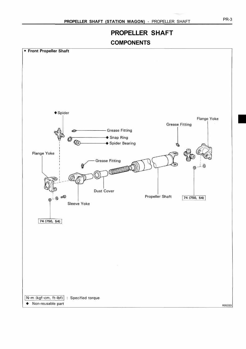
PROPELLER SHAFTCOMPONENTS
PR-4 PROPELLER SHAFT (STATION WAGON) - PROPELLER SHAFT
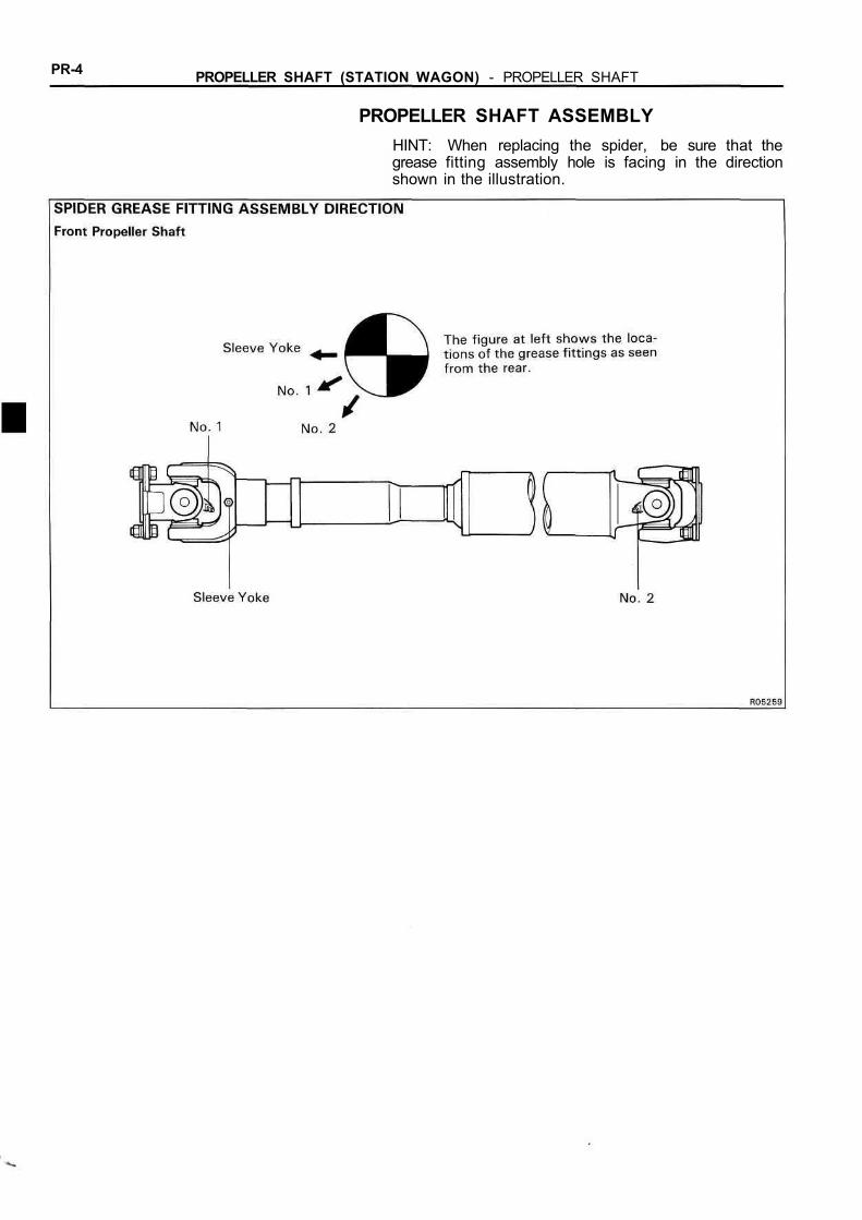
PROPELLER SHAFT ASSEMBLYHINT: When replacing the spider, be sure that thegrease fitting assembly hole is facing in the directionshown in the illustration.
SA-1
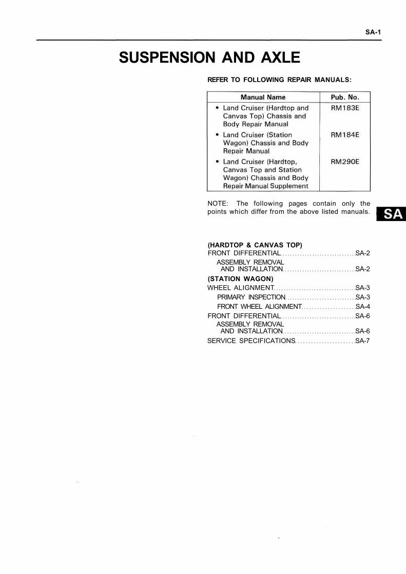
SUSPENSION AND AXLEREFER TO FOLLOWING REPAIR MANUALS:
NOTE: The following pages contain only thepoints which differ from the above listed manuals.
(HARDTOP & CANVAS TOP)FRONT DIFFERENTIAL SA-2
ASSEMBLY REMOVALAND INSTALLATION SA-2
(STATION WAGON)WHEEL ALIGNMENT SA-3
PRIMARY INSPECTION SA-3FRONT WHEEL ALIGNMENT SA-4
FRONT DIFFERENTIAL SA-6ASSEMBLY REMOVAL
AND INSTALLATION SA-6SERVICE SPECIFICATIONS SA-7
SA 2 SUSPENSION AND AXLE (HARDTOP & CANVAS TOP) - FRONT DIFFERENTIAL
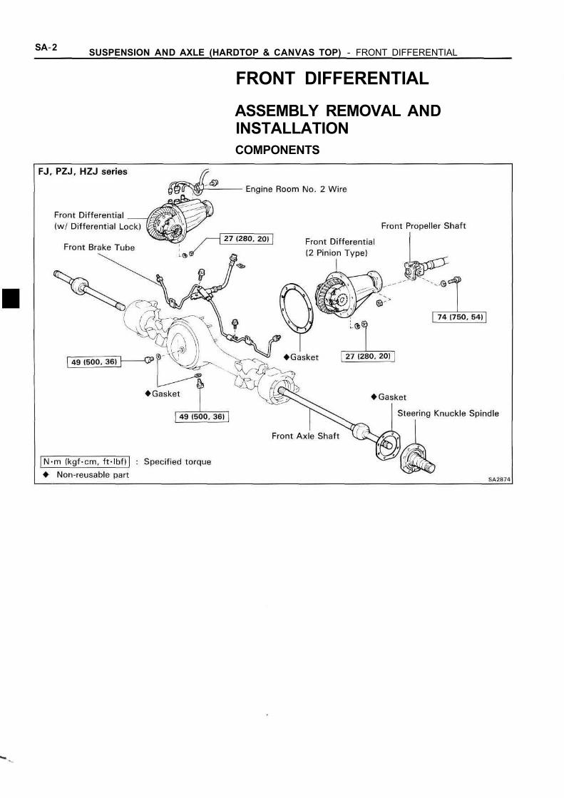
FRONT DIFFERENTIAL
ASSEMBLY REMOVAL ANDINSTALLATIONCOMPONENTS
SUSPENSION AND AXLE (STATION WAGON) - WHEEL ALIGNMENT SA-3
WHEEL ALIGNMENTPRIMARY INSPECTION1. MAKE FOLLOW CHECKS AND CORRECT ANY PRO-
BLEMS(a) Check the tires for wear and proper inflation.
Cold tire inflation pressure:See page SA-7
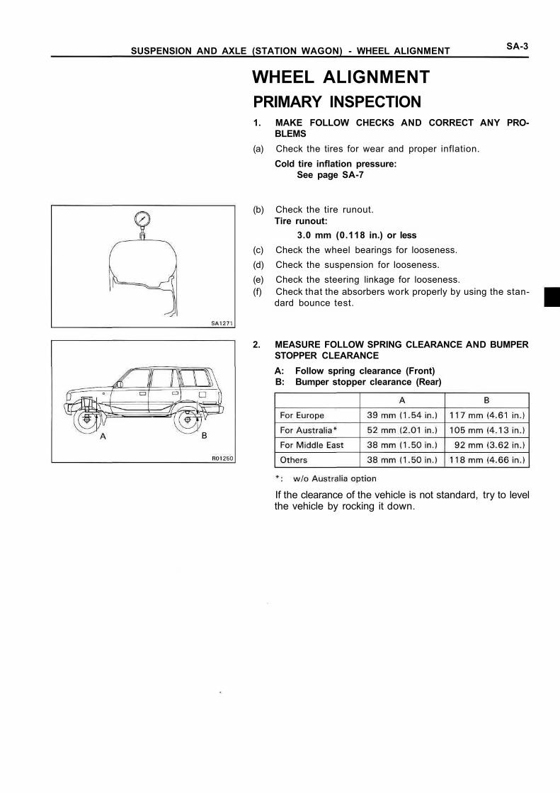
(b) Check the tire runout.Tire runout:
3.0 mm (0.118 in.) or less(c) Check the wheel bearings for looseness.(d) Check the suspension for looseness.(e) Check the steering linkage for looseness.(f) Check that the absorbers work properly by using the stan-
dard bounce test.
2. MEASURE FOLLOW SPRING CLEARANCE AND BUMPERSTOPPER CLEARANCEA: Follow spring clearance (Front)B: Bumper stopper clearance (Rear)
If the clearance of the vehicle is not standard, try to levelthe vehicle by rocking it down.
SA-4 SUSPENSION AND AXLE (STATION WAGON) - WHEEL ALIGNMENT
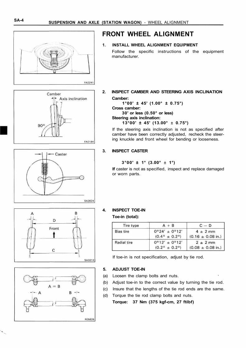
If toe-in is not specification, adjust by tie rod.
5. ADJUST TOE-IN(a) Loosen the clamp bolts and nuts.(b) Adjust toe-in to the correct value by turning the tie rod.(c) Insure that the lengths of the tie rod ends are the same.(d) Torque the tie rod clamp bolts and nuts.
Torque: 37 Nm (375 kgf-cm, 27 ftlbf)
FRONT WHEEL ALIGNMENT1. INSTALL WHEEL ALIGNMENT EQUIPMENT
Follow the specific instructions of the equipmentmanufacturer.
2. INSPECT CAMBER AND STEERING AXIS INCLINATIONCamber:
1°00' ± 45' (1.00° ± 0.75°)Cross camber:
30' or less (0.50° or less)Steering axis inclination:
13°00' ± 45' (13.00° ± 0.75°)If the steering axis inclination is not as specified aftercamber have been correctly adjusted, recheck the steer-ing knuckle and front wheel for bending or looseness.
3. INSPECT CASTER
3°00' ± 1° (3.00° ± 1°)If caster is not as specified, inspect and replace damagedor worn parts.
4. INSPECT TOE-INToe-in (total):
SUSPENSION AND AXLE (STATION WAGON) - WHEEL ALIGNMENT SA-5
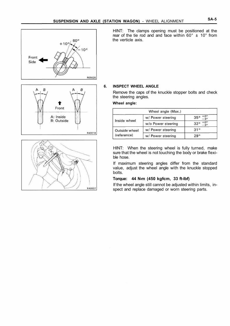
HINT: The clamps opening must be positioned at therear of the tie rod and and face within 60° ± 10° fromthe verticle axis.
6. INSPECT WHEEL ANGLERemove the caps of the knuckle stopper bolts and checkthe steering angles.Wheel angle:
HINT: When the steering wheel is fully turned, makesure that the wheel is not touching the body or brake flexi-ble hose.If maximum steering angles differ from the standardvalue, adjust the wheel angle with the knuckle stoppedbolts.Torque: 44 N-m (450 kgfcm, 33 ft-lbf)If the wheel angle still cannot be adjusted within limits, in-spect and replace damaged or worn steering parts.
SA-6 SUSPENSION AND AXLE (STATION WAGON) - FRONT DIFFERENTIAL
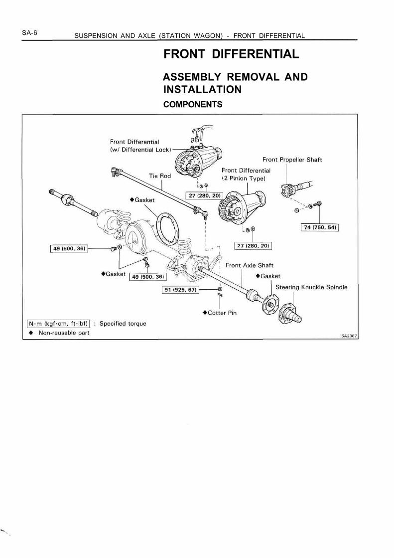
FRONT DIFFERENTIAL
ASSEMBLY REMOVAL ANDINSTALLATIONCOMPONENTS
SUSPENSION AND AXLE - SERVICE SPECIFICATIONS SA-7
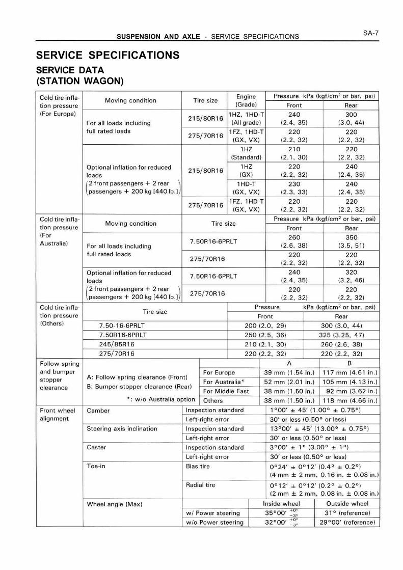
SERVICE SPECIFICATIONSSERVICE DATA(STATION WAGON)
SA-8 SUSPENSION AND AXLE - SERVICE SPECIFICATIONS
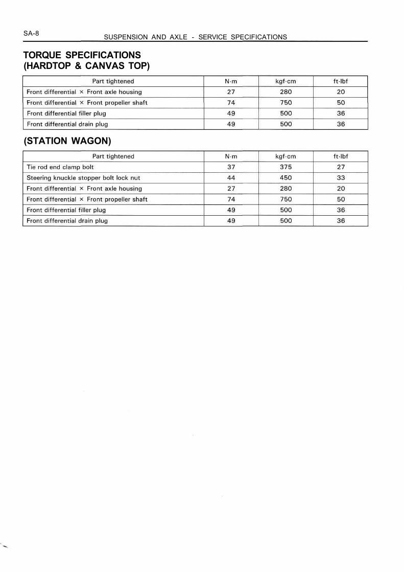
TORQUE SPECIFICATIONS(HARDTOP & CANVAS TOP)
(STATION WAGON)
BR-1
BRAKE SYSTEMREFER TO LAND CRUISER (STATION WAGON)REPAIR MANUAL FOR CHASSIS AND BODY (Pub.No. RM184E)
NOTE: The following pages contain only thepoints which differ from the above listed manual.
(STATION WAGON)PREPARATION BR-2CHECK AND ADJUSTMENT BR-4MASTER CYLINDER BR-6LOAD SENSING PROPORTIONING AND
BY-PASS VALVE (LSP & BV) BR-13ANTI-LOCK BRAKE SYSTEM (ABS) BR-2O
DESCRIPTION BR-2ODIAGNOSIS SYSTEM BR-24SPEED SENSOR AND DECELERATION
SENSOR DIAGNOSIS SYSTEM BR-34DECELERATION SENSOR OPERATION
DIAGNOSIS SYSTEM BR-38ABS ACTUATOR BR-40CONTROL RELAY BR-45FRONT SPEED SENSOR BR-46REAR SPEED SENSOR BR-51ANTI-LOCK BRAKE SYSTEM CIRCUIT BR-55SERVICE SPECIFICATIONS BR-57

BR-2 BRAKE SYSTEM (STATION WAGON) - PREPARATION
PREPARATIONSST (SPECIAL SERVICE TOOLS)
RECOMMENDED TOOLS
EQUIPMENTTorque wrench
09905-00013 Snap Ring Pillers
09082-00015 TOYOTA Electrical Tester
09990-00210 ABS Actuator Checker Sub-harness " E " w/ABS
09990-00200 ABS Actuator Checker Sub-harness " C " w/ ABS
09990-00163 ABS Actuator Checker Sheet " A " w/ ABS
09990-00150 ABS Actuator Checker and Sub-harness w/ABS
09843-18020 Diagnosis Check Wire w/ABS
09751-36011 Brake Tube Union Nut 10 x 12 mmWrench
09737-00010 Brake Booster Push Rod Gauge
09709-29017 LSPV Gauge Set
09023-00100 Union Nut Wrench 10 mm

BR-3BRAKE SYSTEM (STATION WAGON) - PREPARATION
LUBRICANTItem
Brake fluid
Capacity Classification
SAE J17O3 or FMVSS No.116 DOT 3
BR-4 BRAKE SYSTEM (STATION WAGON) - CHECK AND ADJUSTMENT
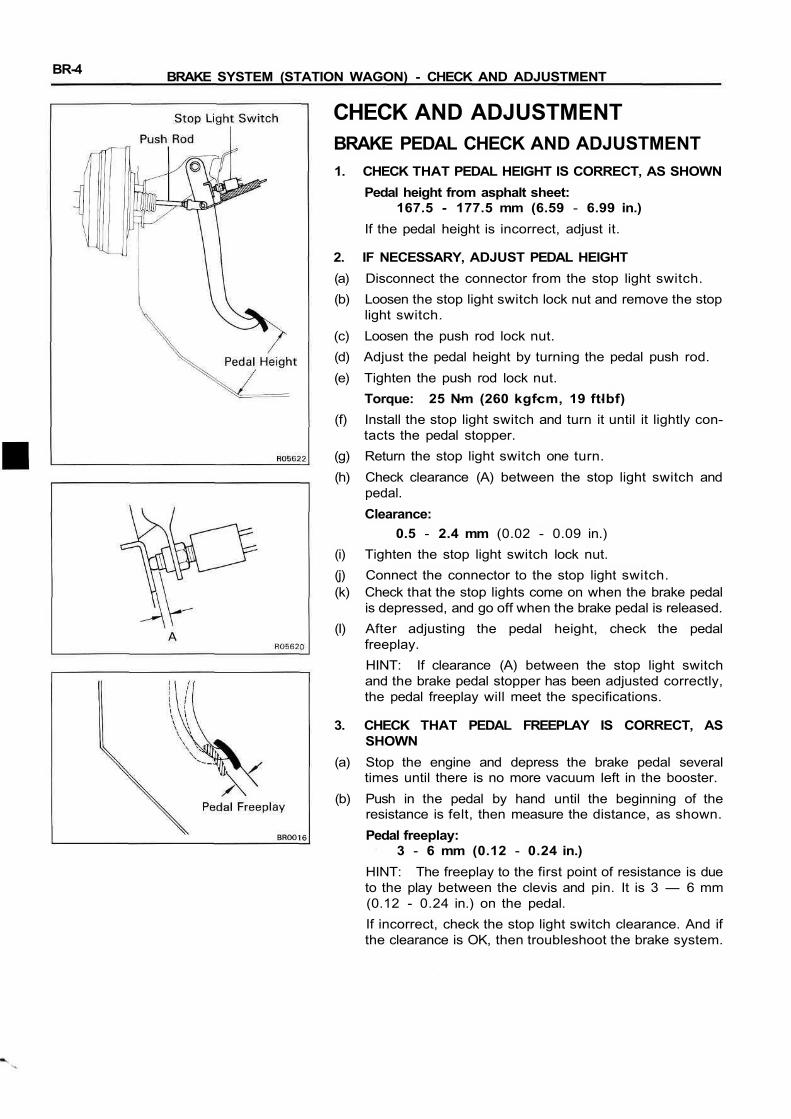
CHECK AND ADJUSTMENTBRAKE PEDAL CHECK AND ADJUSTMENT1. CHECK THAT PEDAL HEIGHT IS CORRECT, AS SHOWN
Pedal height from asphalt sheet:167.5 - 177.5 mm (6.59 - 6.99 in.)
If the pedal height is incorrect, adjust it.
2. IF NECESSARY, ADJUST PEDAL HEIGHT(a) Disconnect the connector from the stop light switch.(b) Loosen the stop light switch lock nut and remove the stop
light switch.(c) Loosen the push rod lock nut.(d) Adjust the pedal height by turning the pedal push rod.(e) Tighten the push rod lock nut.
Torque: 25 Nm (260 kgfcm, 19 ftlbf)(f) Install the stop light switch and turn it until it lightly con-
tacts the pedal stopper.(g) Return the stop light switch one turn.(h) Check clearance (A) between the stop light switch and
pedal.Clearance:
0.5 - 2.4 mm (0.02 - 0.09 in.)(i) Tighten the stop light switch lock nut.(j) Connect the connector to the stop light switch.(k) Check that the stop lights come on when the brake pedal
is depressed, and go off when the brake pedal is released.(I) After adjusting the pedal height, check the pedal
freeplay.HINT: If clearance (A) between the stop light switchand the brake pedal stopper has been adjusted correctly,the pedal freeplay will meet the specifications.
3. CHECK THAT PEDAL FREEPLAY IS CORRECT, ASSHOWN
(a) Stop the engine and depress the brake pedal severaltimes until there is no more vacuum left in the booster.
(b) Push in the pedal by hand until the beginning of theresistance is felt, then measure the distance, as shown.Pedal freeplay:
3 - 6 mm (0.12 - 0.24 in.)HINT: The freeplay to the first point of resistance is dueto the play between the clevis and pin. It is 3 — 6 mm(0.12 - 0.24 in.) on the pedal.If incorrect, check the stop light switch clearance. And ifthe clearance is OK, then troubleshoot the brake system.

BR-5BRAKE SYSTEM (STATION WAGON) - CHECK AND ADJUSTMENT
4. CHECK THAT PEDAL RESERVE DISTANCE IS CORRECT,AS SHOWNRelease the parking brake.With the engine running, depress the pedal and measurethe pedal reserve distance, as shown.Pedal reserve distance from asphalt sheet at 490 N (50kgf, 110.2 Ibf):
More than 68 mm (2.68 in.)If the reserve distance is incorrect, troubleshoot thebrake system.

BR-6 BRAKE SYSTEM (STATION WAGON) - MASTER CYLINDER
MASTER CYLINDERMASTER CYLINDER REMOVAL
Brake Booster
Gasket
Master Cylinder
Clamp
Brake Booster
Gasket
Clamp
Master Cylinder
w/o ABS
Bracketw/ ABS
(RHD)(LHD)
Bracket
3-Way
Specified torqueNon-reusable part
BR-7BRAKE SYSTEM (STATION WAGON) - MASTER CYLINDER
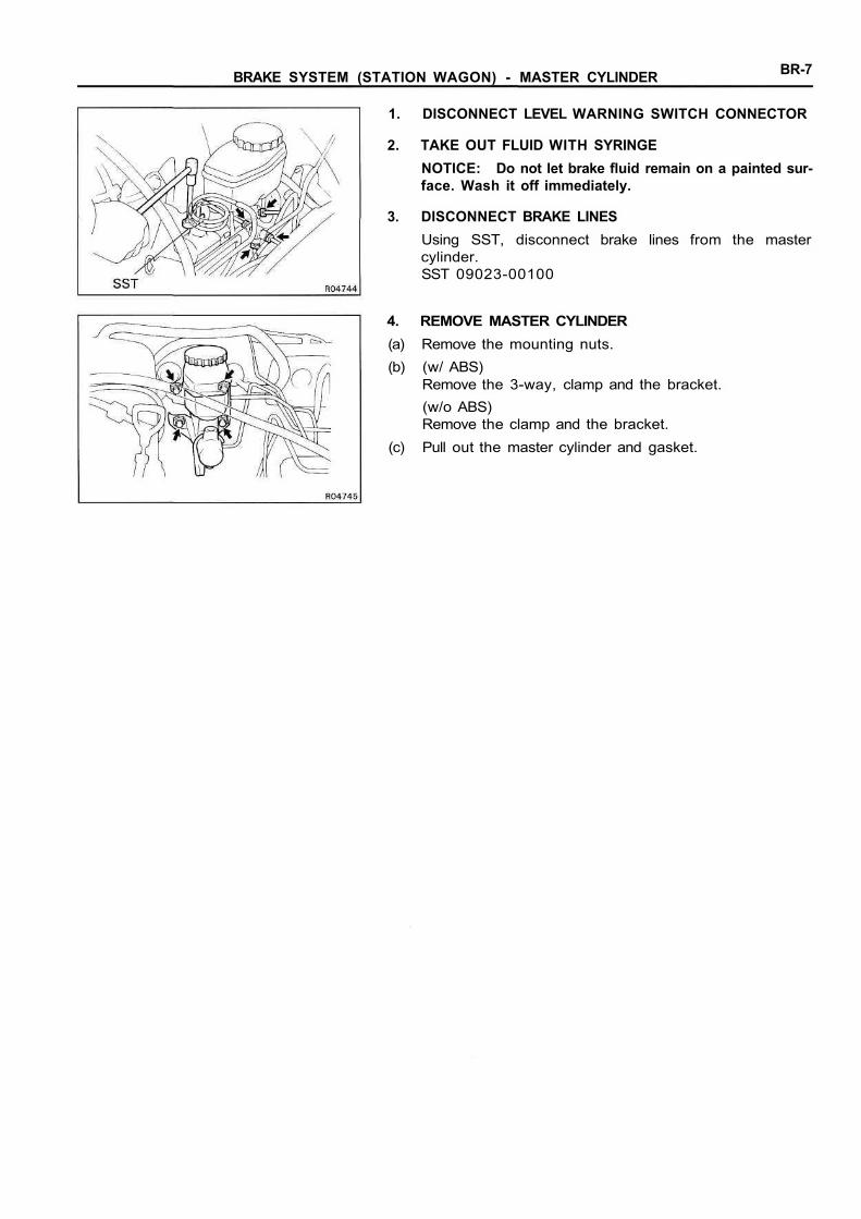
1. DISCONNECT LEVEL WARNING SWITCH CONNECTOR
2. TAKE OUT FLUID WITH SYRINGENOTICE: Do not let brake fluid remain on a painted sur-face. Wash it off immediately.
3. DISCONNECT BRAKE LINESUsing SST, disconnect brake lines from the mastercylinder.SST 09023-00100
4. REMOVE MASTER CYLINDER(a) Remove the mounting nuts.(b) (w/ ABS)
Remove the 3-way, clamp and the bracket.(w/o ABS)Remove the clamp and the bracket.
(c) Pull out the master cylinder and gasket.
BR-8 BRAKE SYSTEM (STATION WAGON) - MASTER CYLINDER
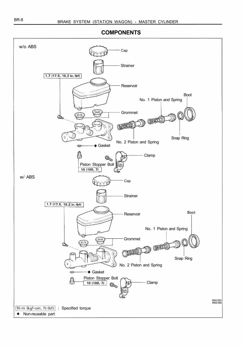
COMPONENTS
w/o ABSCap
Strainer
Reservoir
No. 1 Piston and SpringBoot
Grommet
No. 2 Piston and SpringSnap Ring
Gasket
Clamp
Piston Stopper Bolt
Cap
Strainer
Reservoir
No. 1 Piston and Spring
Grommet
Snap RingNo. 2 Piston and Spring
GasketPiston Stopper Bolt
Clamp
Specified torqueNon-reusable part
w/ ABS
BR-9BRAKE SYSTEM (STATION WAGON) - MASTER CYLINDER
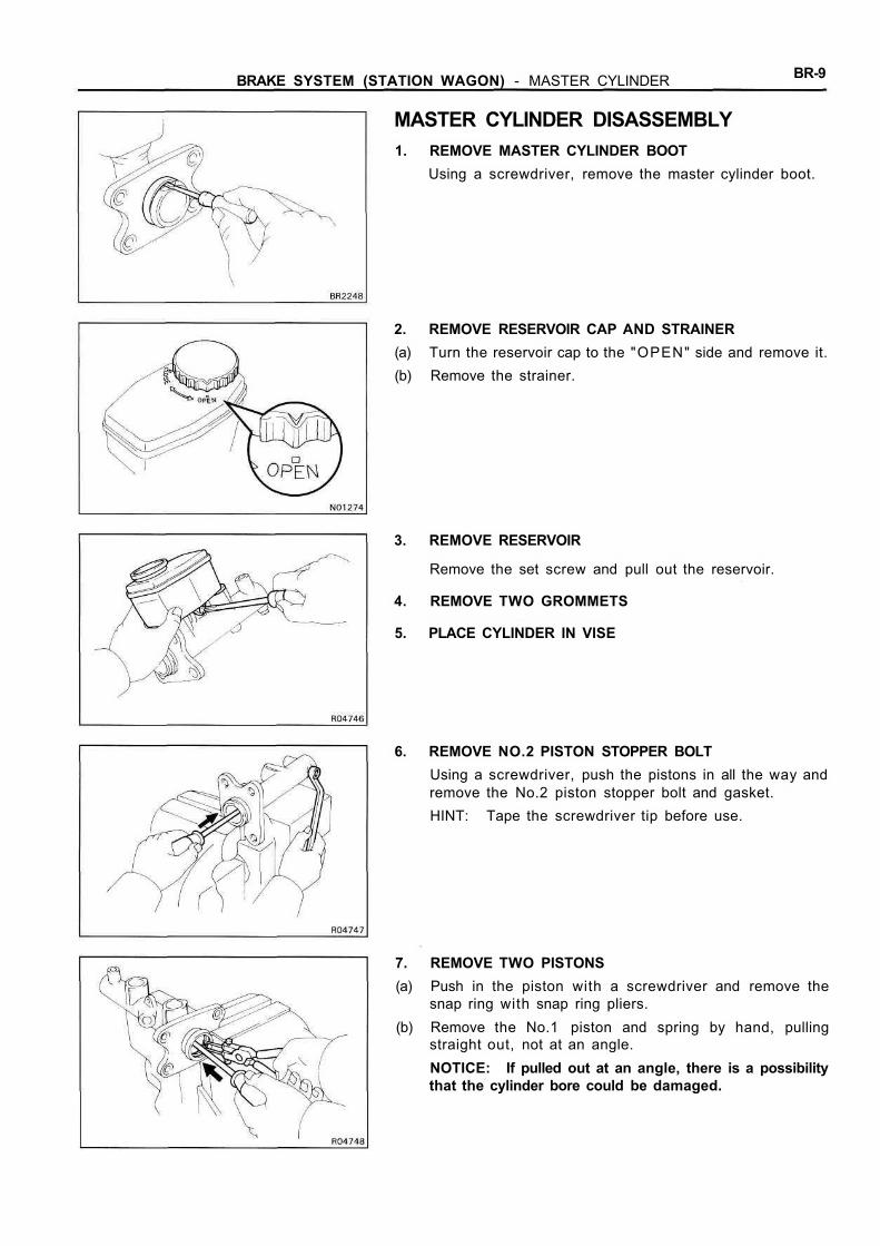
MASTER CYLINDER DISASSEMBLY1. REMOVE MASTER CYLINDER BOOT
Using a screwdriver, remove the master cylinder boot.
2. REMOVE RESERVOIR CAP AND STRAINER(a) Turn the reservoir cap to the "OPEN" side and remove it.(b) Remove the strainer.
3. REMOVE RESERVOIR
Remove the set screw and pull out the reservoir.
4. REMOVE TWO GROMMETS
5. PLACE CYLINDER IN VISE
6. REMOVE NO.2 PISTON STOPPER BOLTUsing a screwdriver, push the pistons in all the way andremove the No.2 piston stopper bolt and gasket.HINT: Tape the screwdriver tip before use.
7. REMOVE TWO PISTONS(a) Push in the piston with a screwdriver and remove the
snap ring with snap ring pliers.(b) Remove the No.1 piston and spring by hand, pulling
straight out, not at an angle.NOTICE: If pulled out at an angle, there is a possibilitythat the cylinder bore could be damaged.
BR-10 BRAKE SYSTEM (STATION WAGON) - MASTER CYLINDER
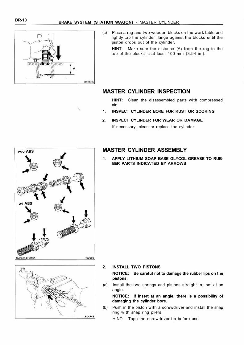
(c) Place a rag and two wooden blocks on the work table andlightly tap the cylinder flange against the blocks until thepiston drops out of the cylinder.HINT: Make sure the distance (A) from the rag to thetop of the blocks is at least 100 mm (3.94 in.).
MASTER CYLINDER INSPECTIONHINT: Clean the disassembled parts with compressedair.
1. INSPECT CYLINDER BORE FOR RUST OR SCORING
2. INSPECT CYLINDER FOR WEAR OR DAMAGEIf necessary, clean or replace the cylinder.
MASTER CYLINDER ASSEMBLY1. APPLY LITHIUM SOAP BASE GLYCOL GREASE TO RUB-
BER PARTS INDICATED BY ARROWS
2. INSTALL TWO PISTONSNOTICE: Be careful not to damage the rubber lips on thepistons.
(a) Install the two springs and pistons straight in, not at anangle.NOTICE: If insert at an angle, there is a possibility ofdamaging the cylinder bore.
(b) Push in the piston with a screwdriver and install the snapring with snap ring pliers.HINT: Tape the screwdriver tip before use.

BR-11BRAKE SYSTEM (STATION WAGON) - MASTER CYLINDER
3. INSTALL NO.2 PISTON STOPPER BOLTUsing a screwdriver, push the piston in all the way and in-stall the No.2 piston stopper bolt over a new gasket.Torque: 10 Nm (100 kgfcm, 7 ftlbf)
4. INSTALL TWO GROMMETS
5. INSTALL RESERVOIR(a) Install the strainer to the reservoir.(b) Push the reservoir onto the cylinder.(c) Install the set screw while pushing on the reservoir.
Torque: 1.7 Nm (17.5 kgfcm, 15.2 in.lbf)
6. INSTALL RESERVOIR CAP(a) Align the matchmark on the reservoir cap with the mat-
chmark on the "OPEN" side of reservoir.(b) Push down on the reservoir cap and turn it clockwise until
it locks.(c) Check that the matchmark on the reservoir cap is now
aligned with the matchmark on the "CLOSE" side of thereservoir.
7. INSTALL MASTER CYLINDER BOOTWith the UP mark on the master cylinder boot facing up-wards, install the cylinder boot on the master cylinder.
MASTER CYLINDER INSTALLATION1. ADJUST LENGTH OF BRAKE BOOSTER PUSH ROD
BEFORE INSTALLING MASTER CYLINDER(See pub. No. RM184E, page BR-26)
BR-12 BRAKE SYSTEM (STATION WAGON) - MASTER CYLINDER
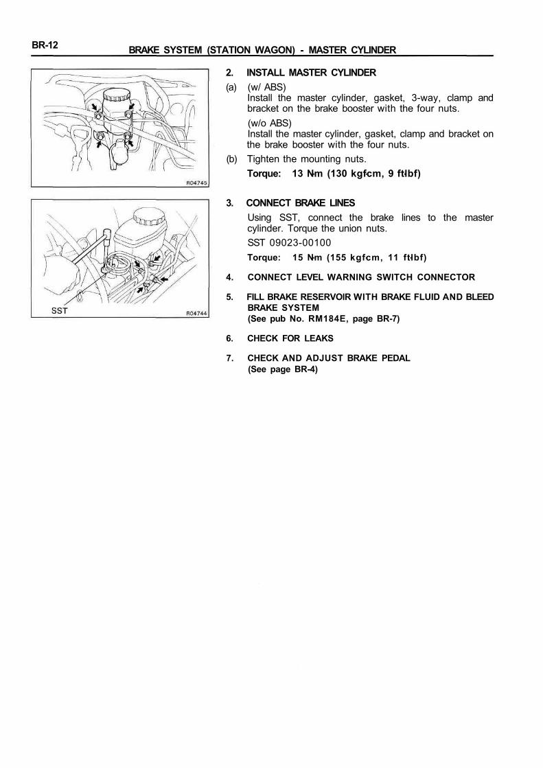
2. INSTALL MASTER CYLINDER(a) (w/ ABS)
Install the master cylinder, gasket, 3-way, clamp andbracket on the brake booster with the four nuts.(w/o ABS)Install the master cylinder, gasket, clamp and bracket onthe brake booster with the four nuts.
(b) Tighten the mounting nuts.Torque: 13 Nm (130 kgfcm, 9 ftlbf)
3. CONNECT BRAKE LINESUsing SST, connect the brake lines to the mastercylinder. Torque the union nuts.SST 09023-00100Torque: 15 Nm (155 kgfcm, 11 ftlbf)
4. CONNECT LEVEL WARNING SWITCH CONNECTOR
5. FILL BRAKE RESERVOIR WITH BRAKE FLUID AND BLEEDBRAKE SYSTEM(See pub No. RM184E, page BR-7)
6. CHECK FOR LEAKS
7. CHECK AND ADJUST BRAKE PEDAL(See page BR-4)
BR-13BRAKE SYSTEM (STATION WAGON) - LOAD SENSING PROPORTIONINGAND BY-PASS VALVE (LSP & BV)
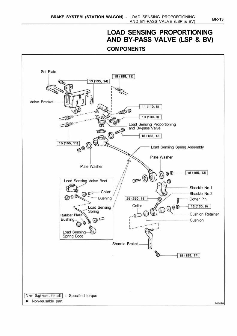
LOAD SENSING PROPORTIONINGAND BY-PASS VALVE (LSP & BV)COMPONENTS
Set Plate
Load Sensing Proportioningand By-pass Valve
Valve Bracket
Load Sensing Spring Assembly
Plate Washer
Plate Washer
Load Sensing Valve Boot
Shackle No.1Shackle No.2Cotter Pin
Collar
Cushion RetainerCushion
Shackle Braket
CollarBushing
Load SensingSpring
Bushing
Load SensingSpring Boot
Specified torqueNon-reusable part

BR-14 BRAKE SYSTEM (STATION WAGON) - LOAD SENSING PROPORTIONINGAND BY-PASS VALVE (LSP & BV)
FLUID PRESSURE CHECK AND ADJUSTMENT1. SET REAR AXLE LOAD
Rear axle load (include vehicle weight):1,330 kg (2,932 Ib)
2. INSTALL LSPV GAUGE (SST) AND BLEED AIRSST 09709-29017
3. RAISE FRONT BRAKE PRESSURE TO 7,845 kPa (80kgf/cm2, 1,138 psi) AND CHECK REAR BRAKEPRESSURERear brake pressure:
5,984 ± 589 kPa (61 ± 6 kgf/cm2, 869 ± 86 psi)HINT: The brake pedal should not be depressed twiceand/or returned while setting to the specified pressure.Read the value of rear pressure two seconds after ad-justing the specified fluid pressure.
4. IF NECESSARY, ADJUST FLUID PRESSURE(a) Disconnect the No.2 shackle from the shackle bracket.(b) Adjust the length of the No.2 shackle turning it.
Low pressure — Lengthen AHigh pressure — Shorten AInitial set:
90 mm (3.54 in.)Adjusting range:
84 - 96 mm (3.31 - 3.78 in.)HINT: One turn of the No.2 shackle changes the fluidpressure about following specification.98.1 kPa (1.0 kgf/cm2, 14.2 psi)
BR-15BRAKE SYSTEM (STATION WAGON) - LOAD SENSING PROPORTIONINGAND BY-PASS VALVE (LSP & BV)
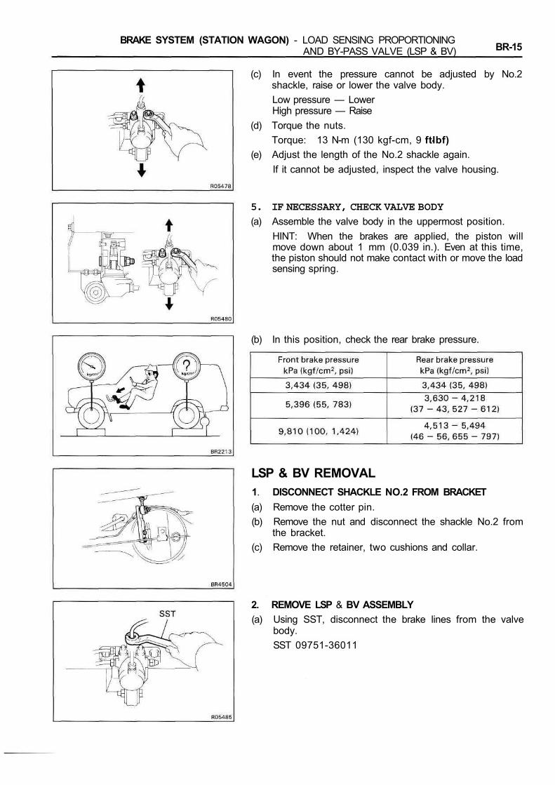
(c) In event the pressure cannot be adjusted by No.2shackle, raise or lower the valve body.Low pressure — LowerHigh pressure — Raise
(d) Torque the nuts.Torque: 13 N-m (130 kgf-cm, 9 ftlbf)
(e) Adjust the length of the No.2 shackle again.If it cannot be adjusted, inspect the valve housing.
5. IF NECESSARY, CHECK VALVE BODY(a) Assemble the valve body in the uppermost position.
HINT: When the brakes are applied, the piston willmove down about 1 mm (0.039 in.). Even at this time,the piston should not make contact with or move the loadsensing spring.
(b) In this position, check the rear brake pressure.
LSP & BV REMOVAL1. DISCONNECT SHACKLE NO.2 FROM BRACKET(a) Remove the cotter pin.(b) Remove the nut and disconnect the shackle No.2 from
the bracket.(c) Remove the retainer, two cushions and collar.
2. REMOVE LSP & BV ASSEMBLY(a) Using SST, disconnect the brake lines from the valve
body.SST 09751-36011
BR-16 BRAKE SYSTEM (STATION WAGON) - LOAD SENSING PROPORTIONINGAND BY-PASS VALVE (LSP & BV)
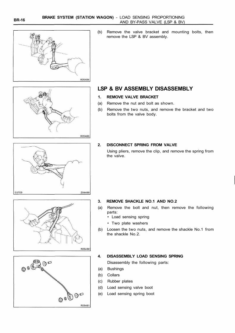
(b) Remove the valve bracket and mounting bolts, thenremove the LSP & BV assembly.
LSP & BV ASSEMBLY DISASSEMBLY1. REMOVE VALVE BRACKET(a) Remove the nut and bolt as shown.(b) Remove the two nuts, and remove the bracket and two
bolts from the valve body.
2. DISCONNECT SPRING FROM VALVEUsing pliers, remove the clip, and remove the spring fromthe valve.
3. REMOVE SHACKLE NO.1 AND NO.2(a) Remove the bolt and nut, then remove the following
parts:• Load sensing spring• Two plate washers
(b) Loosen the two nuts, and remove the shackle No.1 fromthe shackle No.2.
4. DISASSEMBLY LOAD SENSING SPRINGDisassembly the following parts:
(a) Bushings(b) Collars(c) Rubber plates(d) Load sensing valve boot(e) Load sensing spring boot
BR-17BRAKE SYSTEM (STATION WAGON) - LOAD SENSING PROPORTIONINGAND BY-PASS VALVE (LSP & BV)
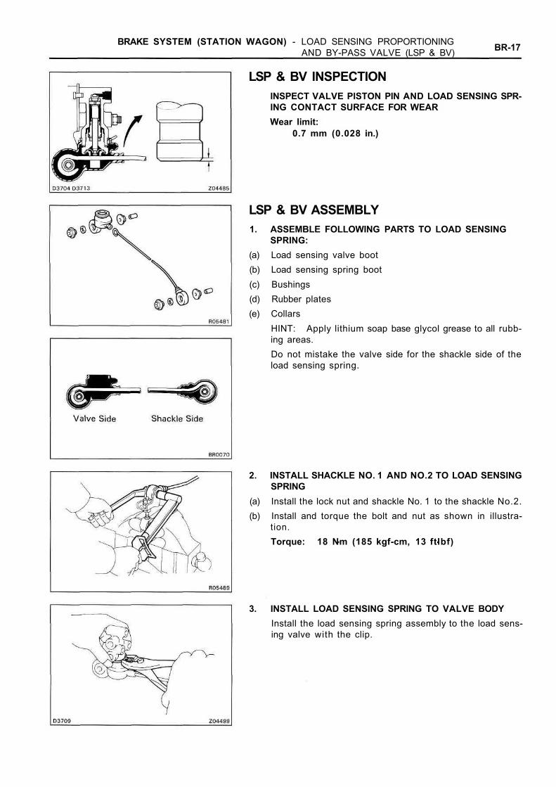
LSP & BV INSPECTIONINSPECT VALVE PISTON PIN AND LOAD SENSING SPR-ING CONTACT SURFACE FOR WEARWear limit:
0.7 mm (0.028 in.)
LSP & BV ASSEMBLY1. ASSEMBLE FOLLOWING PARTS TO LOAD SENSING
SPRING:(a) Load sensing valve boot(b) Load sensing spring boot(c) Bushings(d) Rubber plates(e) Collars
HINT: Apply lithium soap base glycol grease to all rubb-ing areas.Do not mistake the valve side for the shackle side of theload sensing spring.
2. INSTALL SHACKLE NO. 1 AND NO.2 TO LOAD SENSINGSPRING
(a) Install the lock nut and shackle No. 1 to the shackle No.2.(b) Install and torque the bolt and nut as shown in illustra-
tion.Torque: 18 Nm (185 kgf-cm, 13 ftlbf)
3. INSTALL LOAD SENSING SPRING TO VALVE BODYInstall the load sensing spring assembly to the load sens-ing valve with the clip.
BR-18 BRAKE SYSTEM (STATION WAGON) - LOAD SENSING PROPORTIONINGAND BY-PASS VALVE (LSP & BV)
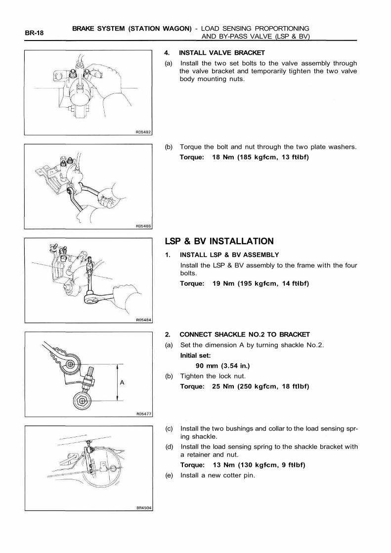
4. INSTALL VALVE BRACKET(a) Install the two set bolts to the valve assembly through
the valve bracket and temporarily tighten the two valvebody mounting nuts.
(b) Torque the bolt and nut through the two plate washers.Torque: 18 Nm (185 kgfcm, 13 ftlbf)
LSP & BV INSTALLATION1. INSTALL LSP & BV ASSEMBLY
Install the LSP & BV assembly to the frame with the fourbolts.Torque: 19 Nm (195 kgfcm, 14 ftlbf)
2. CONNECT SHACKLE NO.2 TO BRACKET(a) Set the dimension A by turning shackle No.2.
Initial set:90 mm (3.54 in.)
(b) Tighten the lock nut.Torque: 25 Nm (250 kgfcm, 18 ftlbf)
(c) Install the two bushings and collar to the load sensing spr-ing shackle.
(d) Install the load sensing spring to the shackle bracket witha retainer and nut.Torque: 13 Nm (130 kgfcm, 9 ftlbf)
(e) Install a new cotter pin.

BRAKE SYSTEM (STATION WAGON) - LOAD SENSING PROPORTIONINGAND BY-PASS VALVE (LSP & BV) BR-19
3. CONNECT BRAKE LINESUsing SST, connect the brake lines.SST 09751-36011Torque: 15 Nm (155 kgfcm, 11 ft-lbf)
4. SET REAR AXLE LOAD(See page BR-16)
5. SET VALVE BODY(a) When pulling down the load sensing spring, confirm that
the valve piston moves down smoothly.(b) Position the valve body so that the valve piston lightly
contacts the load sensing spring.
(c) Tighten the valve body mounting nuts.Torque: 13 Nm (130 kgfcm, 9 ft-lbf)
6. BLEED BRAKE SYSTEM(See pub No. RM184E, page BR-7)
7. CHECK FLUID LEAKAGE
8. CHECK AND ADJUST LSP & BV FLUID PRESSURE(See page BR-16)

BR-20 BRAKE SYSTEM (STATION WAGON) - ANTI-LOCK BRAKE SYSTEM (ABS)
ANTI-LOCK BRAKE SYSTEM (ABS)DESCRIPTION• The ABS is a brake system which controls the brake cylinder hydraulic pressure of all four wheels during
sudden braking and braking on slippery road surfaces, preventing the wheels from locking. This ABS pro-vides the following benefits:(1) Enables steering round an obstacle with a greater degree of certainty even when panic braking.(2) Enables stopping in a panic brake while keeping the effect upon stability and steerability to a
minimum, even on curves.• The function of the ABS is to help maintain directional stability and vehicle steerability on most road condi-
tions. However, the system cannot prevent the vehicle from skidding if the cornering speed limit is ex-ceeded.
• The ABS has a longitudinal deceleration sensor to match braking characteristics to the full-time fourwheel drive.
• In case a malfunction occurs, a diagnosis function and fail-safe system have been adopted for the ABS toincrease serviceability.
• When the center differential is locked, the ABS does not operate, so the ABS warning light lights up to in-dicate this.

BR-21BRAKE SYSTEM (STATION WAGON) - ANTI-LOCK BRAKE SYSTEM (ABS)
COMPONENTS FUNCTIONComponent
Front Speed Sensor
Rear Speed Sensor
ABS Warning Light
Actuator
Function
Detect the wheel speed of each of the left and right front wheels.
Detect the wheel speed of each of the left and right rear wheels.
Lights up to alert the driver when trouble has occurred in the Anti-Lock Brake System and when the center differential is locked.
Controls the brake fluid pressure to each disc brake cylinder throughsignals from the ECU.
From the wheel speed signals from each sensor, it calculates ac-celeration, deceleration and slip values and sends signals to the ac-tuator to control brake fluid pressure.
Detect the deceleration speed of the vehicle and sends a signal ac-cordingly to the ABS ECU.
SYSTEM PARTS LOCATION
Rear Speed SensorsDeceleration SensorABS Warning Light
Control RelayABS Actuator
Front SpeedSensors
Front SpeedSensor Rotors
ABS ECU
Stop LightSwitch
Rear Speed Sensor Rotors
BR-22 BRAKE SYSTEM (STATION WAGON) - ANTI-LOCK BRAKE SYSTEM (ABS)
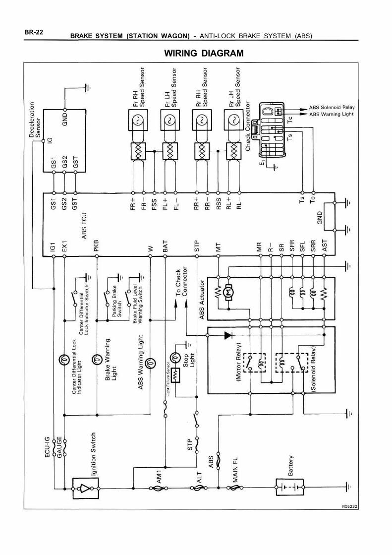
WIRING DIAGRAM
BRAKE SYSTEM (STATION WAGON) - ANTI-LOCK BRAKE SYSTEM (ABS) BR-23
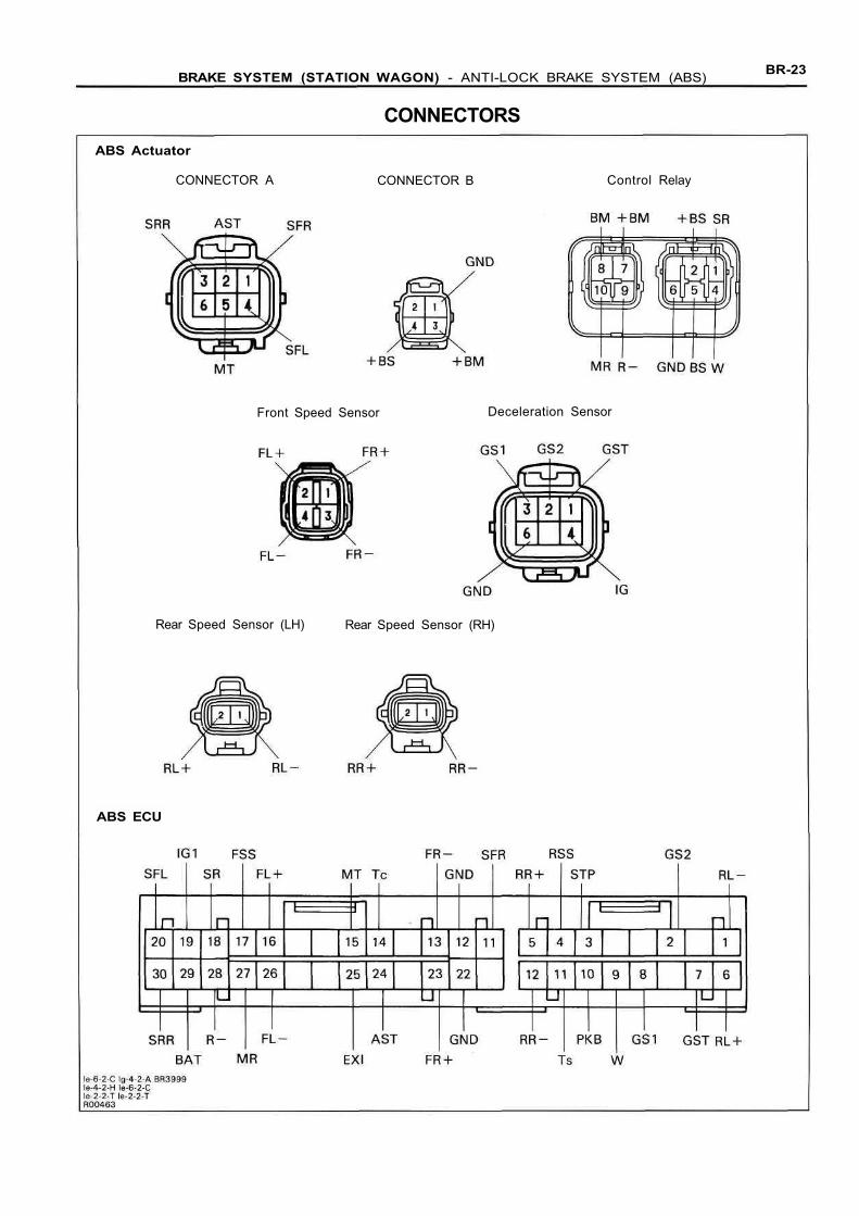
CONNECTORSABS Actuator
CONNECTOR A CONNECTOR B Control Relay
Front Speed Sensor Deceleration Sensor
Rear Speed Sensor (LH) Rear Speed Sensor (RH)
ABS ECU
BR-24 BRAKE SYSTEM (STATION WAGON) - ANTI-LOCK BRAKE SYSTEM (ABS)
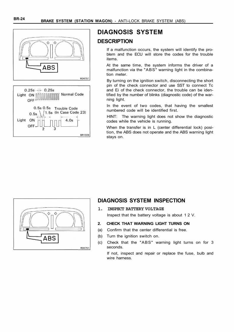
DIAGNOSIS SYSTEMDESCRIPTION
If a malfunction occurs, the system will identify the pro-blem and the ECU will store the codes for the troubleitems.At the same time, the system informs the driver of amalfunction via the "ABS" warning light in the combina-tion meter.By turning on the ignition switch, disconnecting the shortpin of the check connector and use SST to connect Tcand Ei of the check connector, the trouble can be iden-tified by the number of blinks (diagnostic code) of the war-ning light.In the event of two codes, that having the smallestnumbered code will be identified first.HINT: The warning light does not show the diagnosticcodes while the vehicle is running.When the transfer is in L (center differential lock) posi-tion, the ABS does not operate and the ABS warning lightstays on.
DIAGNOSIS SYSTEM INSPECTION1. INSPECT BATTERY VOLTAGE
Inspect that the battery voltage is about 1 2 V.
2. CHECK THAT WARNING LIGHT TURNS ON(a) Confirm that the center differential is free.(b) Turn the ignition switch on.(c) Check that the "ABS" warning light turns on for 3
seconds.If not, inspect and repair or replace the fuse, bulb andwire harness.
BRAKE SYSTEM (STATION WAGON) - ANTI-LOCK BRAKE SYSTEM (ABS) BR-25
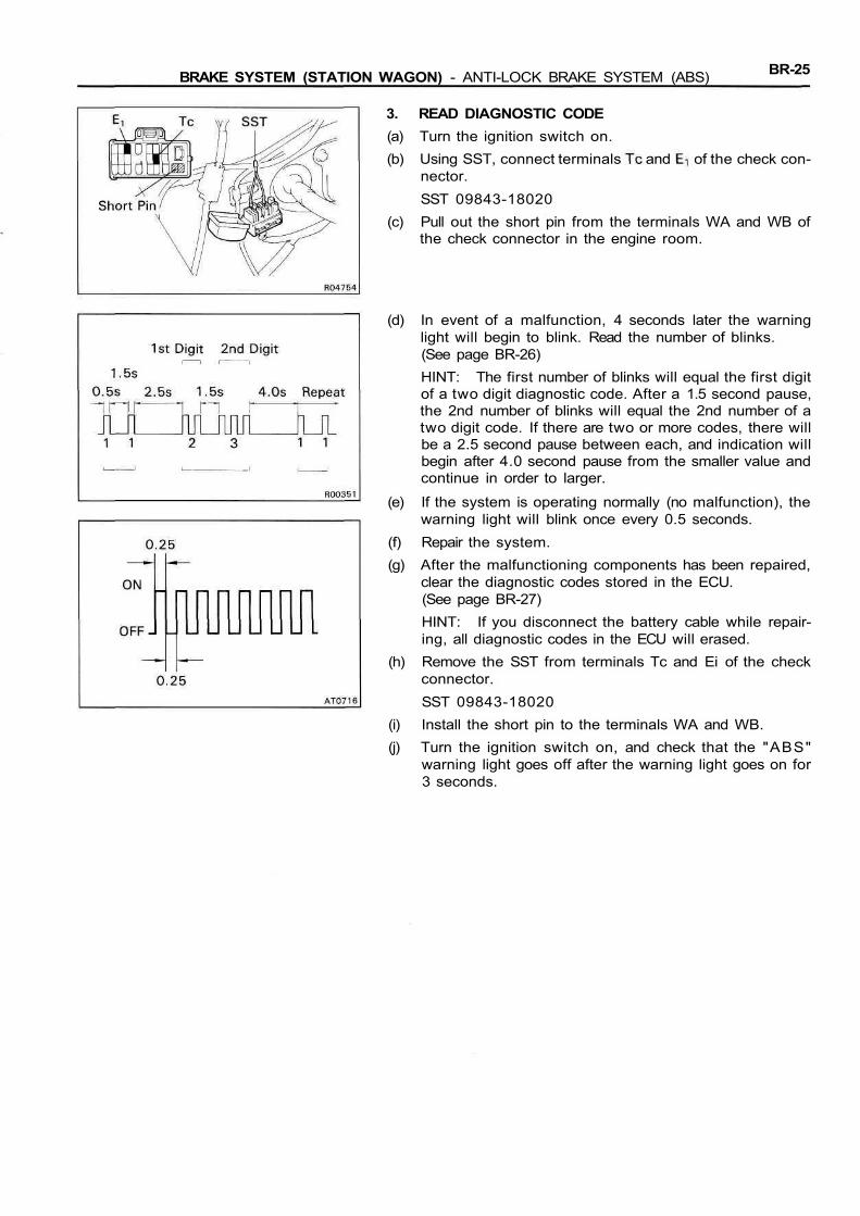
3. READ DIAGNOSTIC CODE(a) Turn the ignition switch on.(b) Using SST, connect terminals and of the check con-
nector.SST 09843-18020
(c) Pull out the short pin from the terminals WA and WB ofthe check connector in the engine room.
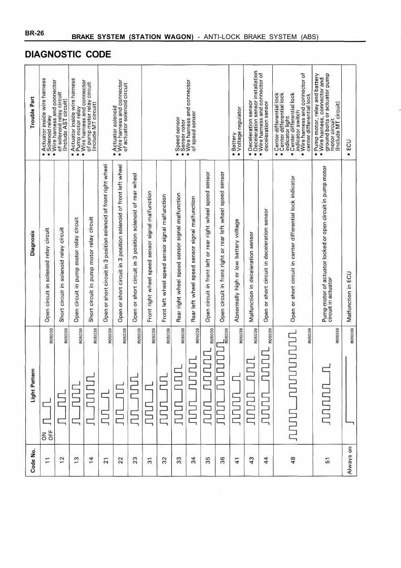
(d) In event of a malfunction, 4 seconds later the warninglight will begin to blink. Read the number of blinks.(See page BR-26)HINT: The first number of blinks will equal the first digitof a two digit diagnostic code. After a 1.5 second pause,the 2nd number of blinks will equal the 2nd number of atwo digit code. If there are two or more codes, there willbe a 2.5 second pause between each, and indication willbegin after 4.0 second pause from the smaller value andcontinue in order to larger.
(e) If the system is operating normally (no malfunction), thewarning light will blink once every 0.5 seconds.
(f) Repair the system.(g) After the malfunctioning components has been repaired,
clear the diagnostic codes stored in the ECU.(See page BR-27)HINT: If you disconnect the battery cable while repair-ing, all diagnostic codes in the ECU will erased.
(h) Remove the SST from terminals Tc and Ei of the checkconnector.SST 09843-18020
(i) Install the short pin to the terminals WA and WB.(j) Turn the ignition switch on, and check that the "ABS"
warning light goes off after the warning light goes on for3 seconds.
BR-26 BRAKE SYSTEM (STATION WAGON) - ANTI-LOCK BRAKE SYSTEM (ABS)
DIAGNOSTIC CODE

BR-27BRAKE SYSTEM (STATION WAGON) - ANTI-LOCK BRAKE SYSTEM (ABS)
DIAGNOSTIC CODES CLEARINGCLEAR DIAGNOSTIC CODES(a) Confirm that the center differential is free.(b) Turn the ignition switch on.(c) Using SST, connect terminals Tc and of the check con-
nector.SST 09843-18020HINT: Keep the vehicle stopped vehicle speed 0 km/h (0mph).
(d) Clear the diagnostic codes stored in ECU by depressingthe brake pedal 8 or more times within 3 seconds.
(e) Check that the warning light shows the normal code.
(f) Remove the SST from terminals Tc and Ei of the checkconnector.SST 09843-18020
(g) Check that the warning light goes off.

BR-28 BRAKE SYSTEM (STATION WAGON) - ANTI-LOCK BRAKE SYSTEM (ABS)
TROUBLESHOOTINGProblem
Always comes on after ignition switch is turned on.Does not come on for 3 seconds after ignition switch on.Goes on and off.Comes on while running.Does not light up when the transfer is in L (center differentiallock) position.Brakes pull.Braking inefficient.ABS operates at ordinary braking.ABS operates just before stopping at ordinary braking.Brake pedal pulsates abnormally while ABS is operating.Skidding noise occurs while ABS operating.(ABS operates inefficiently)When the transfer is in L (center differential lock) position,the ABS operates.
Also check the parts of the brake system (brake cylinders, pads,hydraulic lines, etc.) not specifically part of the ABS.
No.
1
2
3
1
6
4
4
4
4
4
5
6
1 "ABS" warning light comes on.
Is center differential locked (transfer in L position)?
YES
Pull out the short pin and connect terminals andof check connector. (See page BR-25)
Does warning light always come on or show the nor-mal code? (Ignition switch on)
YES
Continued on page BR-29
NO Does the light go off after the center dif-ferential lock is released?
YES
NormalNO
NO See diagnostic code. (See page BR-26)

BR-29BRAKE SYSTEM (STATION WAGON) - ANTI-LOCK BRAKE SYSTEM (ABS)
Continued from page BR-28
Is connector of ECU properly connected?And are all terminals in the connector?
YES
NOFaulty ECU connector.
Is there 10 - 16 V between terminal IG onECU wire harness side connector andbody ground? (Ignition switch on)
NOFaulty power circuit.
YES
Does warning light go off when both theECU connector and service connectorare disconnected? (Ignition switch on)
NO(Come on) Short circuit in wire harness between
ECU terminal W and control relayTerminal W.
YES(Goes off)
Faulty ECU
BR-30 BRAKE SYSTEM (STATION WAGON) - ANTI-LOCK BRAKE SYSTEM (ABS)
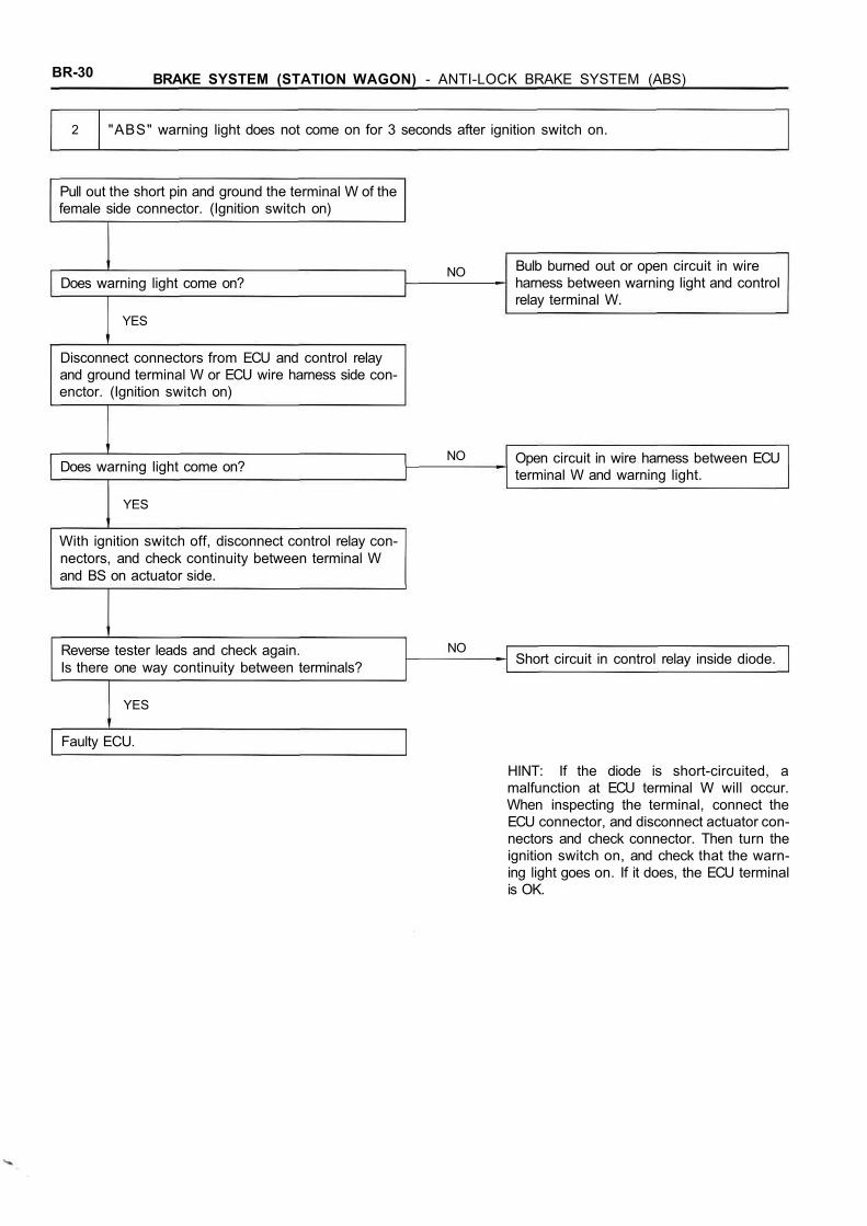
HINT: If the diode is short-circuited, amalfunction at ECU terminal W will occur.When inspecting the terminal, connect theECU connector, and disconnect actuator con-nectors and check connector. Then turn theignition switch on, and check that the warn-ing light goes on. If it does, the ECU terminalis OK.
2 "ABS" warning light does not come on for 3 seconds after ignition switch on.
Pull out the short pin and ground the terminal W of thefemale side connector. (Ignition switch on)
NODoes warning light come on?
Bulb burned out or open circuit in wireharness between warning light and controlrelay terminal W.
YES
Disconnect connectors from ECU and control relayand ground terminal W or ECU wire harness side con-enctor. (Ignition switch on)
Does warning light come on?
YES
NO Open circuit in wire harness between ECUterminal W and warning light.
With ignition switch off, disconnect control relay con-nectors, and check continuity between terminal Wand BS on actuator side.
Reverse tester leads and check again.Is there one way continuity between terminals?
NOShort circuit in control relay inside diode.
YES
Faulty ECU.

BRAKE SYSTEM (STATION WAGON) - ANTI-LOCK BRAKE SYSTEM (ABS) BR-31
3 "ABS" warning light comes on and off.
Check for short circuit in wire harness between terminal and of check connector.
4
Brakes pull.Braking inefficient.ABS operates at ordinary braking.ABS operates just before stopping at ordinary braking.Brake pedal pulsates abnormally while ABS is operating.
Pull out the short pin and connect terminals andof check connector. (See page BR-25)
Does warning light show the diagnostic normal code?(Ignition switch on) See diagnostic code. (See page BR-26)
NO
YES
YES
Are each speed sensors installed in place?And are each installation bolts tightened securely?
NOSpeed sensor installation faulty.
Try speed sensor and deceleration sensor diagnosissystem. Is sensor signal level OK? (See page BR-34)
YES
NOInspect speed sensor, and replace if necessary.
Try speed sensor and deceleration sensor diagnosissystem. Is sensor signal change OK?(See page BR-34)
NOInspect sensor rotor, and replace if necessary.
YES
Disconnect connector from ECU, inspect continuitybetween each speed sensor terminals on wire harnessside. (See page BR-56)
Does any abnormal change occur in continuity whenthe connectors or wire harness of the speed sensorand intermediate connectors are twisted or bent?
YES(Abnormalchange)
Faulty wire harness.
NO(No change)
Continued on page BR-32
BR-32 BRAKE SYSTEM (STATION WAGON) - ANTI-LOCK BRAKE SYSTEM (ABS)
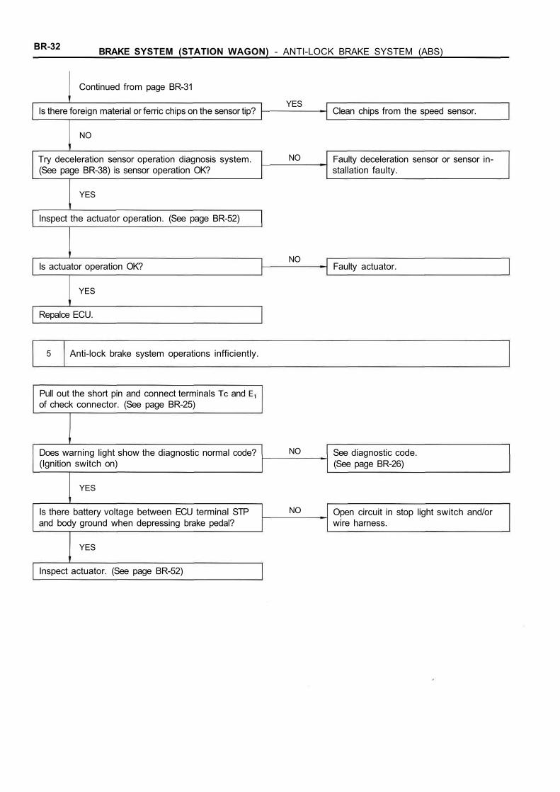
Continued from page BR-31
Is there foreign material or ferric chips on the sensor tip?YES
Clean chips from the speed sensor.
NO
YES
Try deceleration sensor operation diagnosis system.(See page BR-38) is sensor operation OK?
NO Faulty deceleration sensor or sensor in-stallation faulty.
Inspect the actuator operation. (See page BR-52)
Is actuator operation OK?NO
Faulty actuator.
YES
Repalce ECU.
5 Anti-lock brake system operations infficiently.
Pull out the short pin and connect terminals andof check connector. (See page BR-25)
Does warning light show the diagnostic normal code?(Ignition switch on)
NO
YES
See diagnostic code.(See page BR-26)
Is there battery voltage between ECU terminal STPand body ground when depressing brake pedal?
NO Open circuit in stop light switch and/orwire harness.
YES
Inspect actuator. (See page BR-52)
BRAKE SYSTEM (STATION WAGON) - ANTI-LOCK BRAKE SYSTEM (ABS) BR-33
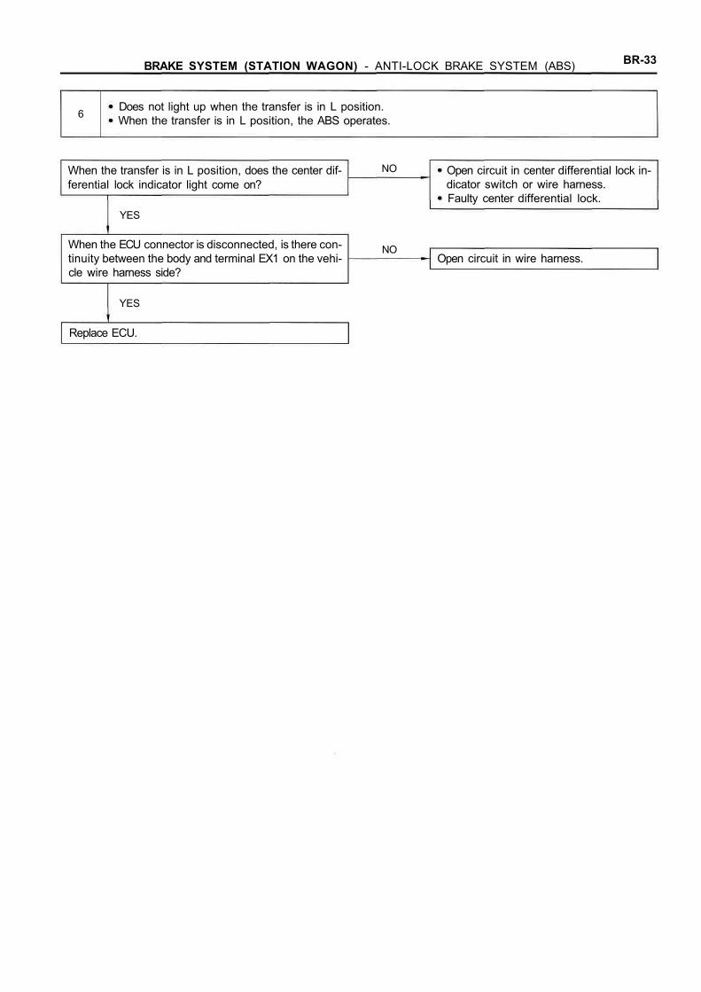
6Does not light up when the transfer is in L position.When the transfer is in L position, the ABS operates.
When the transfer is in L position, does the center dif-ferential lock indicator light come on?
NO Open circuit in center differential lock in-dicator switch or wire harness.Faulty center differential lock.
YES
When the ECU connector is disconnected, is there con-tinuity between the body and terminal EX1 on the vehi-cle wire harness side?
NOOpen circuit in wire harness.
YES
Replace ECU.
BR-34 BRAKE SYSTEM (STATION WAGON) - ANTI-LOCK BRAKE SYSTEM (ABS)
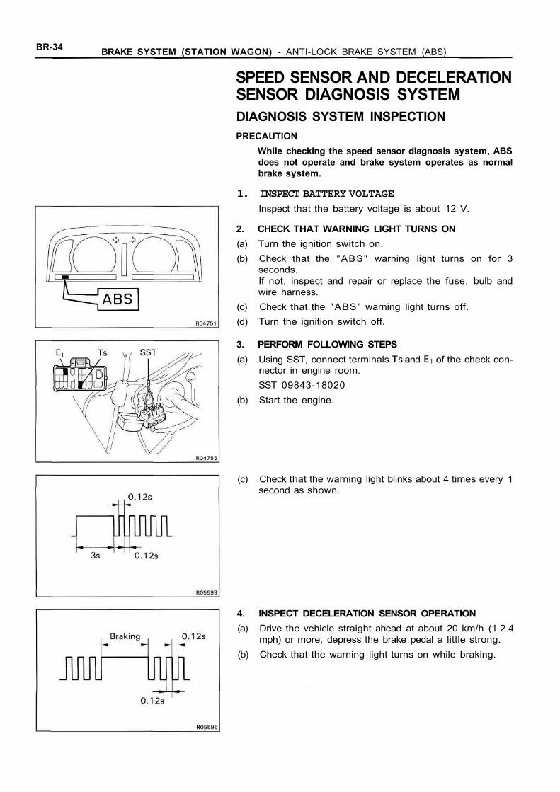
SPEED SENSOR AND DECELERATIONSENSOR DIAGNOSIS SYSTEMDIAGNOSIS SYSTEM INSPECTIONPRECAUTION
While checking the speed sensor diagnosis system, ABSdoes not operate and brake system operates as normalbrake system.
1. INSPECT BATTERY VOLTAGEInspect that the battery voltage is about 12 V.
2. CHECK THAT WARNING LIGHT TURNS ON(a) Turn the ignition switch on.(b) Check that the "ABS" warning light turns on for 3
seconds.If not, inspect and repair or replace the fuse, bulb andwire harness.
(c) Check that the "ABS" warning light turns off.(d) Turn the ignition switch off.
3. PERFORM FOLLOWING STEPS(a) Using SST, connect terminals and of the check con-
nector in engine room.SST 09843-18020
(b) Start the engine.
(c) Check that the warning light blinks about 4 times every 1second as shown.
4. INSPECT DECELERATION SENSOR OPERATION(a) Drive the vehicle straight ahead at about 20 km/h (1 2.4
mph) or more, depress the brake pedal a little strong.(b) Check that the warning light turns on while braking.
BRAKE SYSTEM (STATION WAGON) - ANTI-LOCK BRAKE SYSTEM (ABS) BR-35
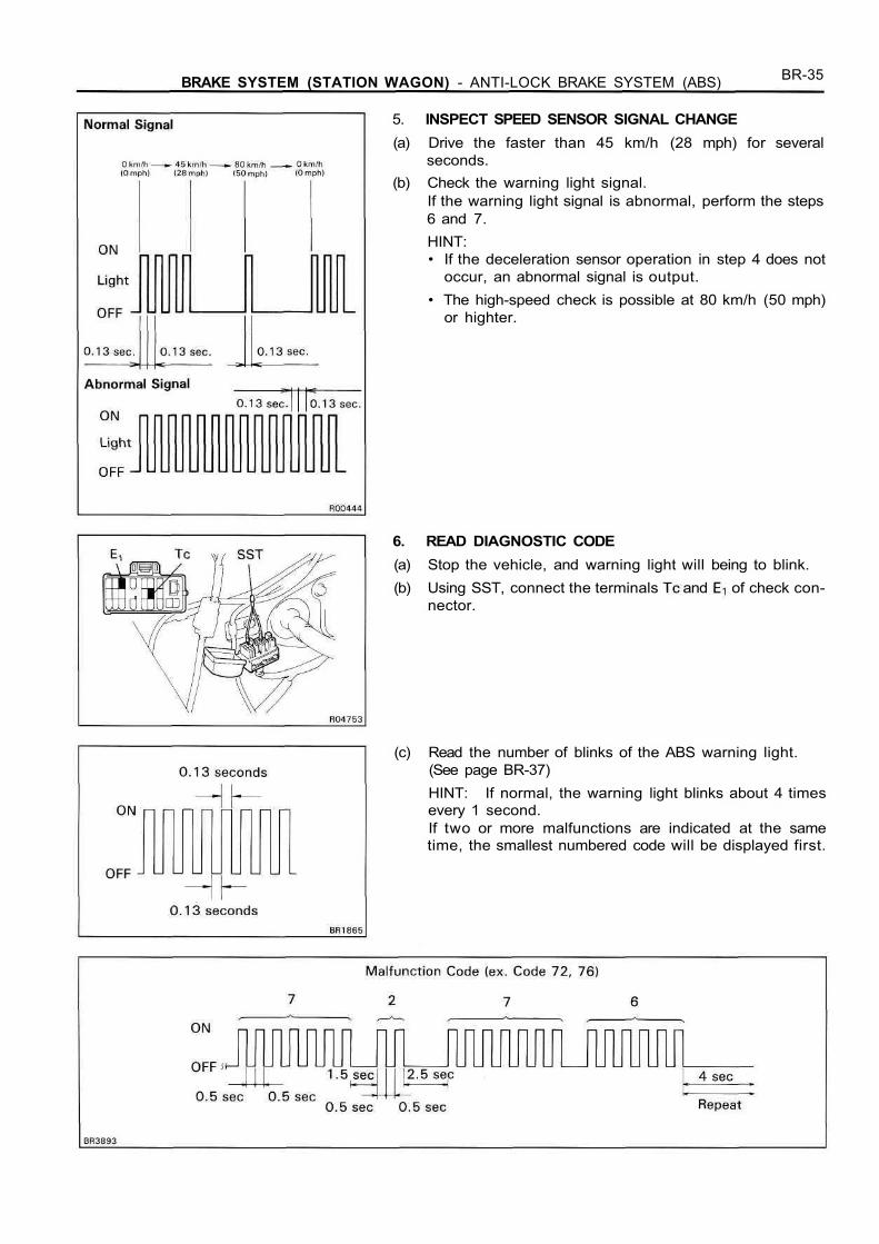
5. INSPECT SPEED SENSOR SIGNAL CHANGE(a) Drive the faster than 45 km/h (28 mph) for several
seconds.(b) Check the warning light signal.
If the warning light signal is abnormal, perform the steps6 and 7.HINT:• If the deceleration sensor operation in step 4 does not
occur, an abnormal signal is output.• The high-speed check is possible at 80 km/h (50 mph)
or highter.
6. READ DIAGNOSTIC CODE(a) Stop the vehicle, and warning light will being to blink.(b) Using SST, connect the terminals and of check con-
nector.
(c) Read the number of blinks of the ABS warning light.(See page BR-37)HINT: If normal, the warning light blinks about 4 timesevery 1 second.If two or more malfunctions are indicated at the sametime, the smallest numbered code will be displayed first.

BR-36 BRAKE SYSTEM (STATION WAGON) - ANTI-LOCK BRAKE SYSTEM (ABS)
7. REPAIR MALFUNCTIONING PARTSRepair or replace the malfunctioning parts.HINT: When repairing or replacing parts, turn the igni-tion switch to OFF.
8. REMOVE SSTRemove the SST from terminals , and of thecheck connector.SST 09843-18020

BR-37BRAKE SYSTEM (STATION WAGON) - ANTI-LOCK BRAKE SYSTEM (ABS)
DIAGNOSTIC CODE
BR-38 BRAKE SYSTEM (STATION WAGON) - ANTI-LOCK BRAKE SYSTEM (ABS)
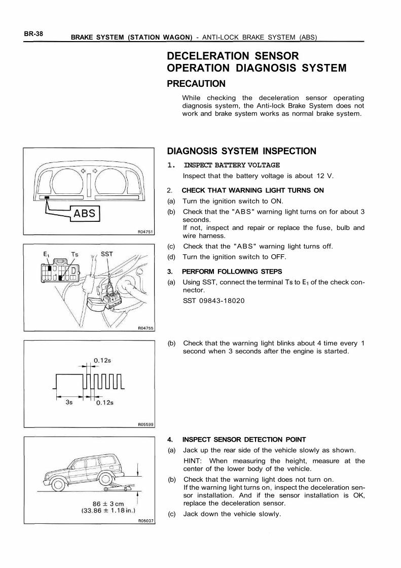
DECELERATION SENSOROPERATION DIAGNOSIS SYSTEMPRECAUTION
While checking the deceleration sensor operatingdiagnosis system, the Anti-lock Brake System does notwork and brake system works as normal brake system.
DIAGNOSIS SYSTEM INSPECTION1. INSPECT BATTERY VOLTAGE
Inspect that the battery voltage is about 12 V.
2. CHECK THAT WARNING LIGHT TURNS ON(a) Turn the ignition switch to ON.(b) Check that the "ABS" warning light turns on for about 3
seconds.If not, inspect and repair or replace the fuse, bulb andwire harness.
(c) Check that the "ABS" warning light turns off.(d) Turn the ignition switch to OFF.
3. PERFORM FOLLOWING STEPS(a) Using SST, connect the terminal to of the check con-
nector.SST 09843-18020
(b) Check that the warning light blinks about 4 time every 1second when 3 seconds after the engine is started.
4. INSPECT SENSOR DETECTION POINT(a) Jack up the rear side of the vehicle slowly as shown.
HINT: When measuring the height, measure at thecenter of the lower body of the vehicle.
(b) Check that the warning light does not turn on.If the warning light turns on, inspect the deceleration sen-sor installation. And if the sensor installation is OK,replace the deceleration sensor.
(c) Jack down the vehicle slowly.
BRAKE SYSTEM (STATION WAGON) - ANTI-LOCK BRAKE SYSTEM (ABS) BR-39
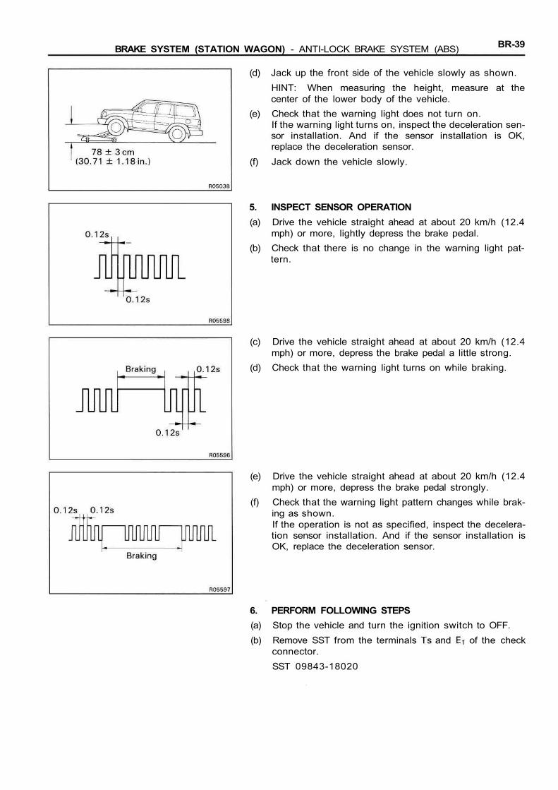
(d) Jack up the front side of the vehicle slowly as shown.HINT: When measuring the height, measure at thecenter of the lower body of the vehicle.
(e) Check that the warning light does not turn on.If the warning light turns on, inspect the deceleration sen-sor installation. And if the sensor installation is OK,replace the deceleration sensor.
(f) Jack down the vehicle slowly.
5. INSPECT SENSOR OPERATION(a) Drive the vehicle straight ahead at about 20 km/h (12.4
mph) or more, lightly depress the brake pedal.(b) Check that there is no change in the warning light pat-
tern.
(c) Drive the vehicle straight ahead at about 20 km/h (12.4mph) or more, depress the brake pedal a little strong.
(d) Check that the warning light turns on while braking.
(e) Drive the vehicle straight ahead at about 20 km/h (12.4mph) or more, depress the brake pedal strongly.
(f) Check that the warning light pattern changes while brak-ing as shown.If the operation is not as specified, inspect the decelera-tion sensor installation. And if the sensor installation isOK, replace the deceleration sensor.
6. PERFORM FOLLOWING STEPS(a) Stop the vehicle and turn the ignition switch to OFF.(b) Remove SST from the terminals and of the check
connector.SST 09843-18020
BR-40 BRAKE SYSTEM (STATION WAGON) - ANTI-LOCK BRAKE SYSTEM (ABS)
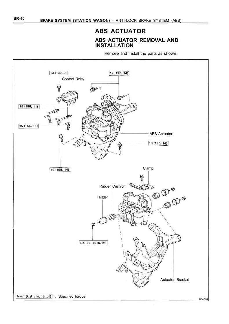
ABS ACTUATORABS ACTUATOR REMOVAL ANDINSTALLATION
Remove and install the parts as shown.
Control Relay
Rubber Cushion
Holder
ABS Actuator
Clamp
Actuator Bracket
Specified torque
BRAKE SYSTEM (STATION WAGON) - ANTI-LOCK BRAKE SYSTEM (ABS) BR-41
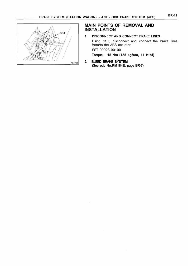
MAIN POINTS OF REMOVAL ANDINSTALLATION1. DISCONNECT AND CONNECT BRAKE LINES
Using SST, disconnect and connect the brake linesfrom/to the ABS actuator.SST 09023-00100Torque: 15 Nm (155 kgfcm, 11 ftlbf)
2. BLEED BRAKE SYSTEM(See pub No.RM184E, page BR-7)

BR-42 BRAKE SYSTEM (STATION WAGON) - ANTI-LOCK BRAKE SYSTEM (ABS)
ABS ACTUATOR INSPECTION1. INSPECT BATTERY VOLTAGE
Battery voltage:10 - 14.5 V
2. DISCONNECT CONNECTORS(a) Disconnect the connector from the actuator.
(b) Remove the control relay from the actuator bracket.(c) Disconnect the two connectors from the control relay.
3. CONNECT ACTUATOR CHECKER (SST) TO ACTUATOR(a) Connect the actuator checker (SST) to the actuator, con-
trol relay and body side wire harness through the sub-wire harness C and E (SST) as shown.SST 09990-00150, 09990-00200, 09990-00210
(b) Connect the red cable of the checker to the batterypositive (+) terminal and black cable to the negative (—)terminal. Connect the black cable of the sub-wire harnessto the battery negative ( —) terminal or body ground.
Sub-Wire Harness C (SST)
Sub-Wire Harness E (SST)
ABSActuator
(Non connected)
SUB
To Body
To Body
ControlRelay
(SST)
BRAKE SYSTEM (STATION WAGON) - ANTI-LOCK BRAKE SYSTEM (ABS) BR-43
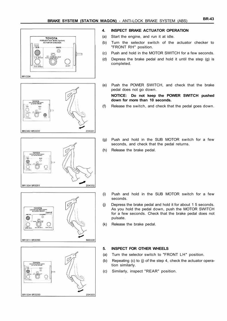
4. INSPECT BRAKE ACTUATOR OPERATION(a) Start the engine, and run it at idle.(b) Turn the selector switch of the actuator checker to
"FRONT RH" position.(c) Push and hold in the MOTOR SWITCH for a few seconds.(d) Depress the brake pedal and hold it until the step (g) is
completed.
(e) Push the POWER SWITCH, and check that the brakepedal does not go down.NOTICE: Do not keep the POWER SWITCH pusheddown for more than 10 seconds.
(f) Release the switch, and check that the pedal goes down.
(g) Push and hold in the SUB MOTOR switch for a fewseconds, and check that the pedal returns.
(h) Release the brake pedal.
(i) Push and hold in the SUB MOTOR switch for a fewseconds.
(j) Depress the brake pedal and hold it for about 1 5 seconds.As you hold the pedal down, push the MOTOR SWITCHfor a few seconds. Check that the brake pedal does notpulsate.
(k) Release the brake pedal.
5. INSPECT FOR OTHER WHEELS(a) Turn the selector switch to "FRONT LH" position.(b) Repeating (c) to (j) of the step 4, check the actuator opera-
tion similarly.(c) Similarly, inspect "REAR" position.

BR-44 BRAKE SYSTEM (STATION WAGON) - ANTI-LOCK BRAKE SYSTEM (ABS)
6. PUSH SUB MOTOR SWITCH(a) Push and hold in the SUB MOTOR switch for a few
seconds.(b) Stop the engine.
7. DISCONNECT ACTUATOR CHECKER (SST) FROM AC-TUATORDisconnect the actuator checker (SST) and sub-wireharness (SST) from the actuator, control relay and bodyside wire harness.SST 09990-00150, 09990-00200, 09990-00210
8. CONNECT CONNECTORS(a) Connect the two connectors to the control relay.
(b) Connect the connector to the actuator.(c) Install the control relay to the actuator bracket.
9. CLEAR DIAGNOSTIC CODES(See page BR-27)
BRAKE SYSTEM (STATION WAGON) - ANTI-LOCK BRAKE SYSTEM (ABS) BR-45
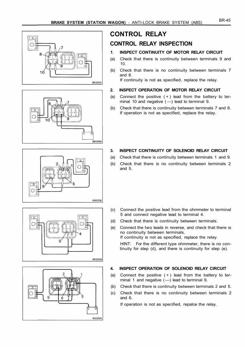
CONTROL RELAYCONTROL RELAY INSPECTION1. INSPECT CONTINUITY OF MOTOR RELAY CIRCUIT(a) Check that there is continuity between terminals 9 and
10.(b) Check that there is no continuity between terminals 7
and 8.If continuity is not as specified, replace the relay.
2. INSPECT OPERATION OF MOTOR RELAY CIRCUIT(a) Connect the positive ( + ) lead from the battery to ter-
minal 10 and negative ( —) lead to terminal 9.(b) Check that there is continuity between terminals 7 and 8.
If operation is not as specified, replace the relay.
3. INSPECT CONTINUITY OF SOLENOID RELAY CIRCUIT(a) Check that there is continuity between terminals 1 and 9.(b) Check that there is no continuity between terminals 2
and 5.
(c) Connect the positive lead from the ohmmeter to terminal5 and connect negative lead to terminal 4.
(d) Check that there is continuity between terminals.(e) Connect the two leads in reverse, and check that there is
no continuity between terminals.If continuity is not as specified, replace the relay.HINT: For the different type ohmmeter, there is no con-tinuity for step (d), and there is continuity for step (e).
4. INSPECT OPERATION OF SOLENOID RELAY CIRCUIT(a) Connect the positive ( + ) lead from the battery to ter-
minal 1 and negative ( —) lead to terminal 9.(b) Check that there is continuity between terminals 2 and 5.(c) Check that there is no continuity between terminals 2
and 6.If operation is not as specified, repalce the relay.
BR-46 BRAKE SYSTEM (STATION WAGON) - ANTI-LOCK BRAKE SYSTEM (ABS)
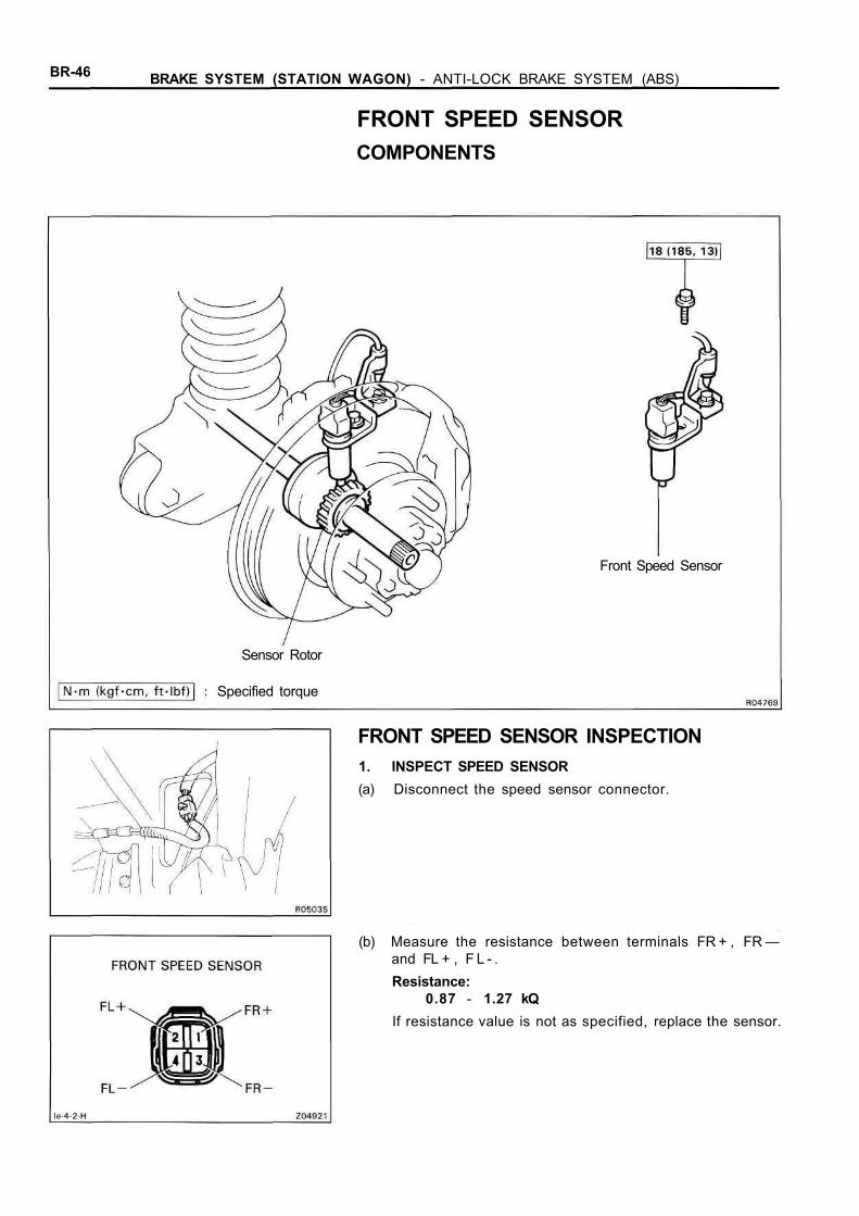
FRONT SPEED SENSORCOMPONENTS
Front Speed Sensor
Sensor Rotor
Specified torque
FRONT SPEED SENSOR INSPECTION1. INSPECT SPEED SENSOR(a) Disconnect the speed sensor connector.
(b) Measure the resistance between terminals FR + , FR —and FL + , F L - .Resistance:
0.87 - 1.27 kQIf resistance value is not as specified, replace the sensor.

BRAKE SYSTEM (STATION WAGON) - ANTI-LOCK BRAKE SYSTEM (ABS) BR-47
(c) Check that there is no continuity between each terminaland sensor body.If there is continuity, replace the sensor.
(d) Connect the speed sensor connector.
2. INSPECT SENSOR INSTALLATIONCheck that the sensor installation bolt is tightened proper-ly. If not, tighten the bolt.Torque: 18 Nm (184 kgf-cm, 13 ft-lbf)
3. VISUALLY INSPECT SENSOR ROTOR SERRATIONS(a) Remove the axle hub with disc.
(See pub No. RM184E, page SA-16)(b) Inspect the sensor rotor serrations for scratches, cracks,
warping or missing teeth.(c) Install the axle hub with disc.
(See pub No. RM184E, page SA-19)
FRONT SPEED SENSOR AND SENSOR ROTORSERRATIONS INSPECTION(REFERENCE)INSPECT FRONT SPEED SENSOR AND SENSOR ROTOR SER-RATIONS BY USING AN OSCILLOSCOPE(a) Connect an oscilloscope to the speed sensor connector.(b) Run the vehicle at 20 km/h (12.4 mph), and inspect
speed sensor output wave.(c) Check that C is 0.5 V or more.
If not as specified, replace the speed sensor.(d) Check that B is 50 % or more of A.
If not as specified, replace the sensor rotor.
BR-48 BRAKE SYSTEM (STATION WAGON) - ANTI-LOCK BRAKE SYSTEM (ABS)
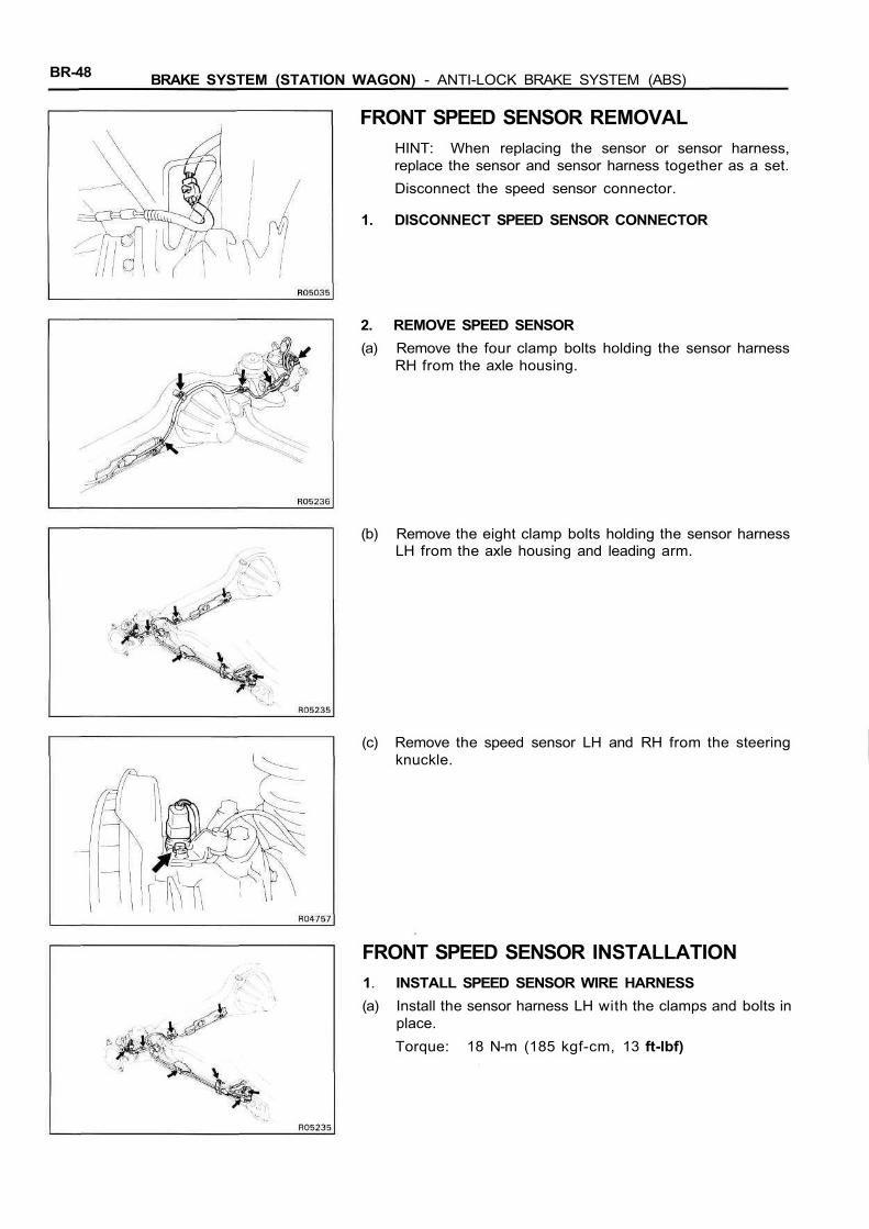
FRONT SPEED SENSOR REMOVALHINT: When replacing the sensor or sensor harness,replace the sensor and sensor harness together as a set.Disconnect the speed sensor connector.
1. DISCONNECT SPEED SENSOR CONNECTOR
2. REMOVE SPEED SENSOR(a) Remove the four clamp bolts holding the sensor harness
RH from the axle housing.
(b) Remove the eight clamp bolts holding the sensor harnessLH from the axle housing and leading arm.
(c) Remove the speed sensor LH and RH from the steeringknuckle.
FRONT SPEED SENSOR INSTALLATION1. INSTALL SPEED SENSOR WIRE HARNESS(a) Install the sensor harness LH with the clamps and bolts in
place.Torque: 18 N-m (185 kgf-cm, 13 ft-lbf)
BRAKE SYSTEM (STATION WAGON) - ANTI-LOCK BRAKE SYSTEM (ABS) BR-49
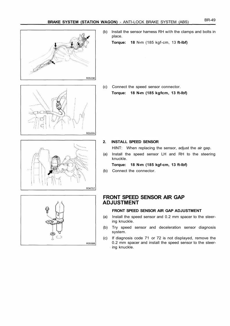
(b) Install the sensor harness RH with the clamps and bolts inplace.Torque: 18 N-m (185 kgf-cm, 13 ft-lbf)
(c) Connect the speed sensor connector.Torque: 18 N-m (185 kgfcm, 13 ft-lbf)
2. INSTALL SPEED SENSORHINT: When replacing the sensor, adjust the air gap.
(a) Install the speed sensor LH and RH to the steeringknuckle.Torque: 18 N-m (185 kgf-cm, 13 ft-lbf)
(b) Connect the connector.
FRONT SPEED SENSOR AIR GAPADJUSTMENT
FRONT SPEED SENSOR AIR GAP ADJUSTMENT(a) Install the speed sensor and 0.2 mm spacer to the steer-
ing knuckle.(b) Try speed sensor and deceleration sensor diagnosis
system.(c) If diagnosis code 71 or 72 is not displayed, remove the
0.2 mm spacer and install the speed sensor to the steer-ing knuckle.

BR-50 BRAKE SYSTEM (STATION WAGON) - ANTI-LOCK BRAKE SYSTEM (ABS)
(d) If diagnosis code 71 or 72 is displayed, replace the 0.5mm spacer inserted in the speed sensor with a 0.35 mmspacer.(1) Using a screwdriver to remove the 0.5 mm spacer.
(2) Using needle-nose pliers to install the 0.35 mmspacer.
(e) Repeating (a) and (b) to the step 1.(f) If diagnosis code 71 or 72 is not displayed, remove the
0.2 mm spacer and install the speed sensor to the steer-ing knuckle.
(g) If diagnosis code 71 or 72 is displayed, replace the 0.35mm spacer with a 0.25 mm spacer.
(h) Repeating (a) and (b) to the step 1.(i) If diagnosis code 71 or 72 is not displayed, remove the
0.2 mm spacer and install the speed sensor to the steer-ing knuckle.
(j) If diagnosis code 71 or 72 is displayed, replace the 0.25mm spacer with a 0.1 5 mm spacer and install the speedsensor to the steeing knuckle without using the 0.2 mmspacer.
BRAKE SYSTEM (STATION WAGON) - ANTI-LOCK BRAKE SYSTEM (ABS) BR-51
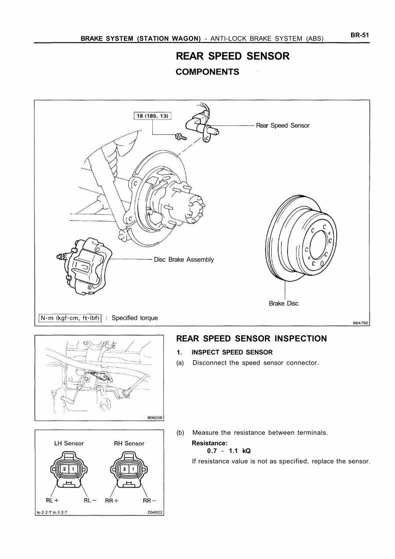
REAR SPEED SENSORCOMPONENTS
Rear Speed Sensor
Disc Brake Assembly
Specified torque
Brake Disc
REAR SPEED SENSOR INSPECTION1. INSPECT SPEED SENSOR(a) Disconnect the speed sensor connector.
(b) Measure the resistance between terminals.Resistance:
0.7 - 1.1 kQIf resistance value is not as specified, replace the sensor.

BR-52 BRAKE SYSTEM (STATION WAGON) - ANTI-LOCK BRAKE SYSTEM (ABS)
(c) Check that there is no continuity between each terminaland sensor body.If there is continuity, replace the sensor.
(d) Connect the speed sensor connector.
2. INSPECT SENSOR INSTALLATIONCheck that the sensor installation bolt is tightened proper-ly. If not, tighten the bolt.Torque: 18 N-m (185 kgf-cm, 13 ftlbf)
3. VISUALLY INSPECT SENSOR ROTOR SERRATIONS(a) Remove the brake disc.
(See pub No. RM184E, page BR-57)(b) Inspect the sensor rotor serrations for scratches, cracks,
warping or missing teeth.(c) Install the brake disc.
(See pub No. RM184E, page BR-64)NOTICE: To prevent damage to the serrations, do notstrike the axle hub.
REAR SPEED SENSOR AND SENSOR ROTORSERRATIONS INSPECTION(REFERENCE)INSPECT REAR SPEED SENSOR AND SENSOR ROTOR SERRA-TIONS BY USING AN OSCILLOSCOPE(a) Connect an oscilloscope to the speed sensor connector.(b) Run the vehicle at 20 km/h (12.4 mph), and inspect
speed sensor output wave.(c) Check that C is 0.5 V or more.
If not as specified, replace the speed sensor.(d) Check that B is 50 % or more of A.
If not as specified, replace the rear axle hub.
BRAKE SYSTEM (STATION WAGON) - ANTI-LOCK BRAKE SYSTEM (ABS) BR-53
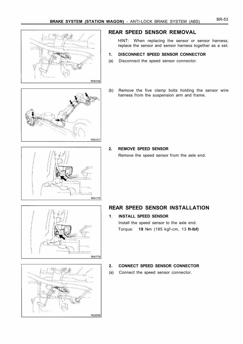
REAR SPEED SENSOR REMOVALHINT: When replacing the sensor or sensor harness,replace the sensor and sensor harness together as a set.
1. DISCONNECT SPEED SENSOR CONNECTOR(a) Disconnect the speed sensor connector.
(b) Remove the five clamp bolts holding the sensor wireharness from the suspension arm and frame.
2. REMOVE SPEED SENSORRemove the speed sensor from the axle end.
REAR SPEED SENSOR INSTALLATION1. INSTALL SPEED SENSOR
Install the speed sensor to the axle end.Torque: 18 Nm (185 kgf-cm, 13 ft-lbf)
2. CONNECT SPEED SENSOR CONNECTOR(a) Connect the speed sensor connector.
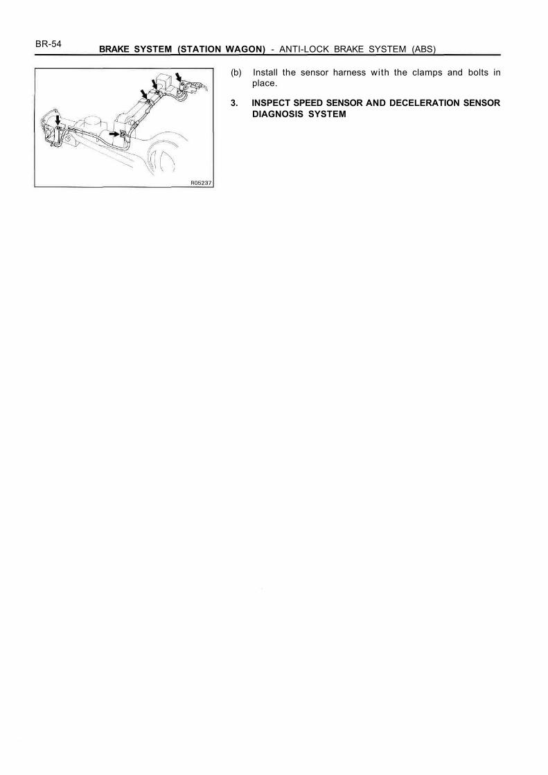
BR-54 BRAKE SYSTEM (STATION WAGON) - ANTI-LOCK BRAKE SYSTEM (ABS)
(b) Install the sensor harness with the clamps and bolts inplace.
3. INSPECT SPEED SENSOR AND DECELERATION SENSORDIAGNOSIS SYSTEM

BRAKE SYSTEM (STATION WAGON) - ANTI-LOCK BRAKE SYSTEM (ABS) BR-55
ANTI-LOCK BRAKE SYSTEMCIRCUITSYSTEM CIRCUIT INSPECTION1. INSPECT SYSTEM CIRCUIT WITH CONNECTOR CON-
NECTED(a) Remove the ABS ECU.(b) Using a voltmeter with high impedance (10 kfl/V
minimum), measure the voltage at each terminal andbody ground.
BR-56 BRAKE SYSTEM (STATION WAGON) - ANTI-LOCK BRAKE SYSTEM (ABS)
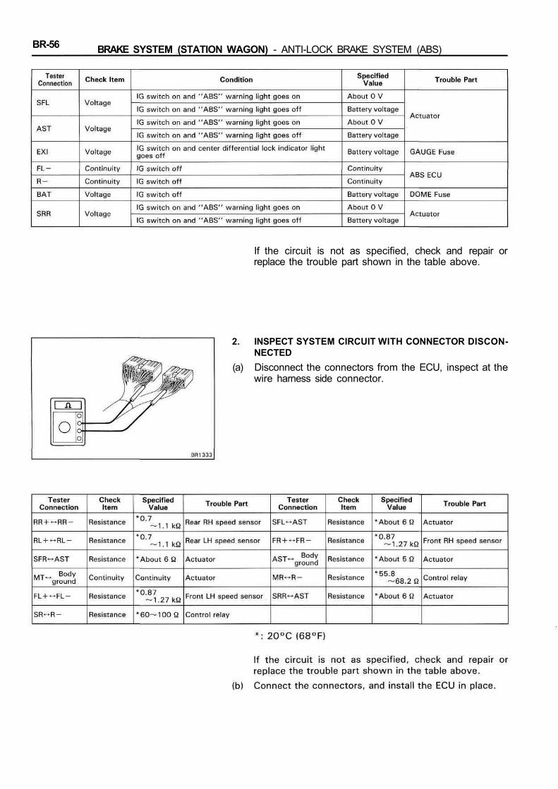
If the circuit is not as specified, check and repair orreplace the trouble part shown in the table above.
2. INSPECT SYSTEM CIRCUIT WITH CONNECTOR DISCON-NECTED
(a) Disconnect the connectors from the ECU, inspect at thewire harness side connector.
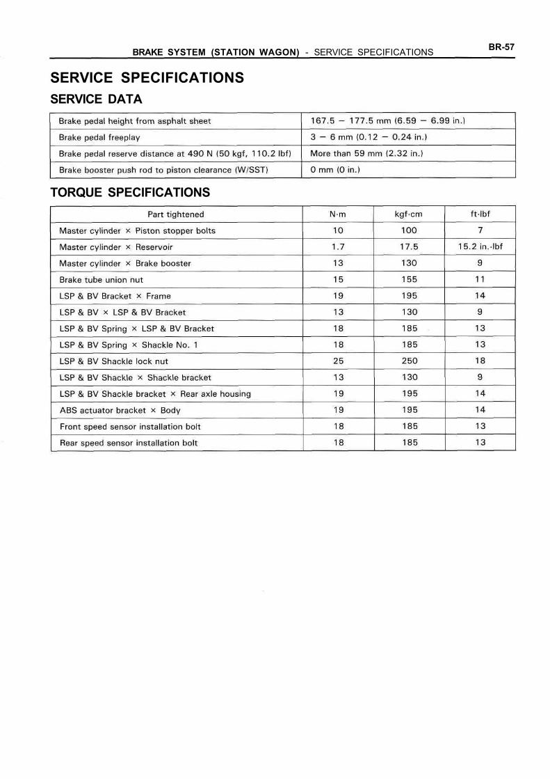
BRAKE SYSTEM (STATION WAGON) - SERVICE SPECIFICATIONS BR-57
SERVICE SPECIFICATIONSSERVICE DATA
TORQUE SPECIFICATIONS