Propeller loss involving Jabiru Insert document title … loss involving Jabiru J430, VH-TJP North...
24
ATSB Transport Safety Report Investigation Propeller loss involving Jabiru J430, VH-TJP Investigation North of French Island, Victoria | 8 March 2013 ATSB Transport Safety Report Aviation Occurrence Investigation AO-2013-046 Final – 19 August 2014
Transcript of Propeller loss involving Jabiru Insert document title … loss involving Jabiru J430, VH-TJP North...

Insert document title
Location | Date
ATSB Transport Safety Report[Insert Mode] Occurrence InvestigationXX-YYYY-####Final
Investigation
Propeller loss involving JabiruJ430, VH-TJP
Investigation
North of French Island, Victoria | 8 March 2013
ATSB Transport Safety ReportAviation Occurrence InvestigationAO-2013-046Final – 19 August 2014

Released in accordance with section 25 of the Transport Safety Investigation Act 2003
Publishing information
Published by: Australian Transport Safety Bureau Postal address: PO Box 967, Civic Square ACT 2608 Office: 62 Northbourne Avenue Canberra, Australian Capital Territory 2601 Telephone: 1800 020 616, from overseas +61 2 6257 4150 (24 hours) Accident and incident notification: 1800 011 034 (24 hours) Facsimile: 02 6247 3117, from overseas +61 2 6247 3117 Email: [email protected] Internet: www.atsb.gov.au
© Commonwealth of Australia 2014
Ownership of intellectual property rights in this publication Unless otherwise noted, copyright (and any other intellectual property rights, if any) in this publication is owned by the Commonwealth of Australia.
Creative Commons licence With the exception of the Coat of Arms, ATSB logo, and photos and graphics in which a third party holds copyright, this publication is licensed under a Creative Commons Attribution 3.0 Australia licence.
Creative Commons Attribution 3.0 Australia Licence is a standard form license agreement that allows you to copy, distribute, transmit and adapt this publication provided that you attribute the work.
The ATSB’s preference is that you attribute this publication (and any material sourced from it) using the following wording: Source: Australian Transport Safety Bureau
Copyright in material obtained from other agencies, private individuals or organisations, belongs to those agencies, individuals or organisations. Where you want to use their material you will need to contact them directly. Addendum
Page Change Date

Safety summary
What happened On 8 March 2013, during climb after departure from Tyabb aerodrome, Victoria, the pilot and sole occupant of a Jabiru J430 aircraft, registered VH-TJP, reported the onset of vibration through the airframe. As a precaution, the pilot began to turn the aircraft back towards Tyabb. During the turn, the propeller separated from the aircraft, necessitating a forced landing upon tidal flats at the western edge of Westernport Bay. The pilot was not injured and was able to disembark the aircraft safely.
What the ATSB found The ATSB investigation found that most of the cap screws connecting the propeller mounting flange to the engine crankshaft had failed by bending fatigue fracture – principally due to repeated relative movement between the mounted components. This movement was traced to a combination of an ineffective, multi-step torqueing method and the relaxation of tension within the crank–flange joint due to the compression of multiple layers of paint within the joint. It was also found that there were some anomalies within the maintenance documentation that related to these areas.
After attempting to analyse the origin of the worsening vibration in the aircraft, the pilot correctly followed emergency procedures both before and after the propeller loss. The over-water return decision limited the risks associated with the forced landing, and the pilot effectively maintained control of the aircraft throughout the descent and landing.
What's been done as a result In July 2011, the manufacturer had improved the strength and reliability of the crank–flange joint by adding positive-location dowels in all new-production engines. However, that modification was not extended to earlier design assemblies, which included VH-TJP. The current (revised) issue of the Engine Overhaul Manual has an added, strong recommendation for inclusion of these dowels at the next full overhaul or at bulk strip of engines manufactured prior to July 2011. Furthermore, in addition to the earlier requirement for no paint on mating faces or where screw heads bear, a broad requirement was introduced to ensure that no paint, thread-locking compound or contaminants remain in the propeller flange joint. The fastener torqueing method has been amended to a single-step process in which the required torque is to be obtained dynamically while the fastener is being turned.
Finally, the manufacturer’s Propeller Flange Attachment Service Bulletin now refers maintainers directly to the engine overhaul manual for installation procedures – removing the variability that previously existed between documents.
Safety message A potentially serious accident was avoided by the pilot’s adherence to emergency procedures and maintaining control of the aircraft after a significant mechanical failure.
Regarding the mechanical assembly, the ATSB encourages manufacturers and maintainers to consider older and legacy operating assemblies when designs are optimised or improved to enhance safety and reliability.
VH-TJP in flight
Source: VH-TJP Pilot

Contents
The occurrence ........................................................................................................................1 Context ......................................................................................................................................2 Safety analysis .........................................................................................................................8
Occurrence flight 8 Screw failures 8 Insufficient joint clamping 8 Document anomalies 9
Findings ................................................................................................................................. 10 Contributing factors 10 Other findings 10
Safety issues and actions ................................................................................................... 11 Engines with undoweled crankshaft–propeller flange joints 11
Safety issue description: 11 Current status of the safety issue: 11
Insufficient joint clamping 11 Safety issue description: 11 Current status of the safety issue: 12
Document anomalies 12 Safety issue description: 12 Current status of the safety issue: 12
General details ...................................................................................................................... 13 Occurrence details 13 Aircraft details 13
Sources and submissions .................................................................................................. 14 Sources of information 14 References 14 Submissions 14
Appendix A ............................................................................................................................ 15 Australian Transport Safety Bureau .................................................................................. 17
Purpose of safety investigations 17 Developing safety action 17

› 1 ‹
ATSB – AO-2013-046
The occurrence On 8 March 2013, the pilot and sole occupant of a Jabiru J430 aircraft, registered VH-TJP (TJP), refuelled at Tyabb, Victoria and took off from runway 17, making a left turn towards French Island in Westernport Bay. During the subsequent climb to 2,000 ft, the pilot began to feel vibrations through the aircraft that progressively became more severe. The pilot unsuccessfully tried to identify their source by adjusting the engine controls. Approximately 18 km from the aerodrome, while heading in a south-easterly direction, the pilot elected to return to Tyabb. During the turn, the propeller separated from the aircraft and, relieved of its load, the engine speed surged before the pilot brought it under control. Exposed tidal flats at the western edge of the bay were identified as suitable for a forced landing, which was successfully carried out. The pilot was uninjured and after disembarking, he took photographs of the now-exposed end of the crankshaft, minus the propeller flange and propeller (Figure 1). The incoming tide later submersed and substantially damaged the aircraft.
The intact wooden propeller/spinner assembly was found the following day by the Victorian Water Police, floating north-west of French Island about 5 km from the western shore of the bay.
Figure 1: Forward end of TJP’s crankshaft showing five broken screws
Source: VH-TJP Pilot
Aircraft information TJP was an amateur-built Jabiru J430 kit aircraft, serial number 567, with a six-cylinder, 3300 cm3,
Jabiru engine (serial number 33A1693) fitted. The aircraft was constructed and assembled in 2007 by its owners (with factory assistance) and was first registered on 13 November 2007.
In October 2012, the aircraft underwent periodic inspection and maintenance; in addition, the propeller and mounting flange were removed because of rust. After derusting, cleaning, priming and painting, the components were re-installed in accordance with revisions of the relevant Service Bulletins1 current at the time, using new cap screws and bolts. At the time of that maintenance, the aircraft’s total time in service (TTIS) was 297.5 hours. The propeller separation occurred 3.7 flying hours later. 1 JSB 009-1 Alternate (sic) Propeller Mount System and JSB 022-1 Propeller Flange Attachment.
› 2 ‹
ATSB – AO-2013-046
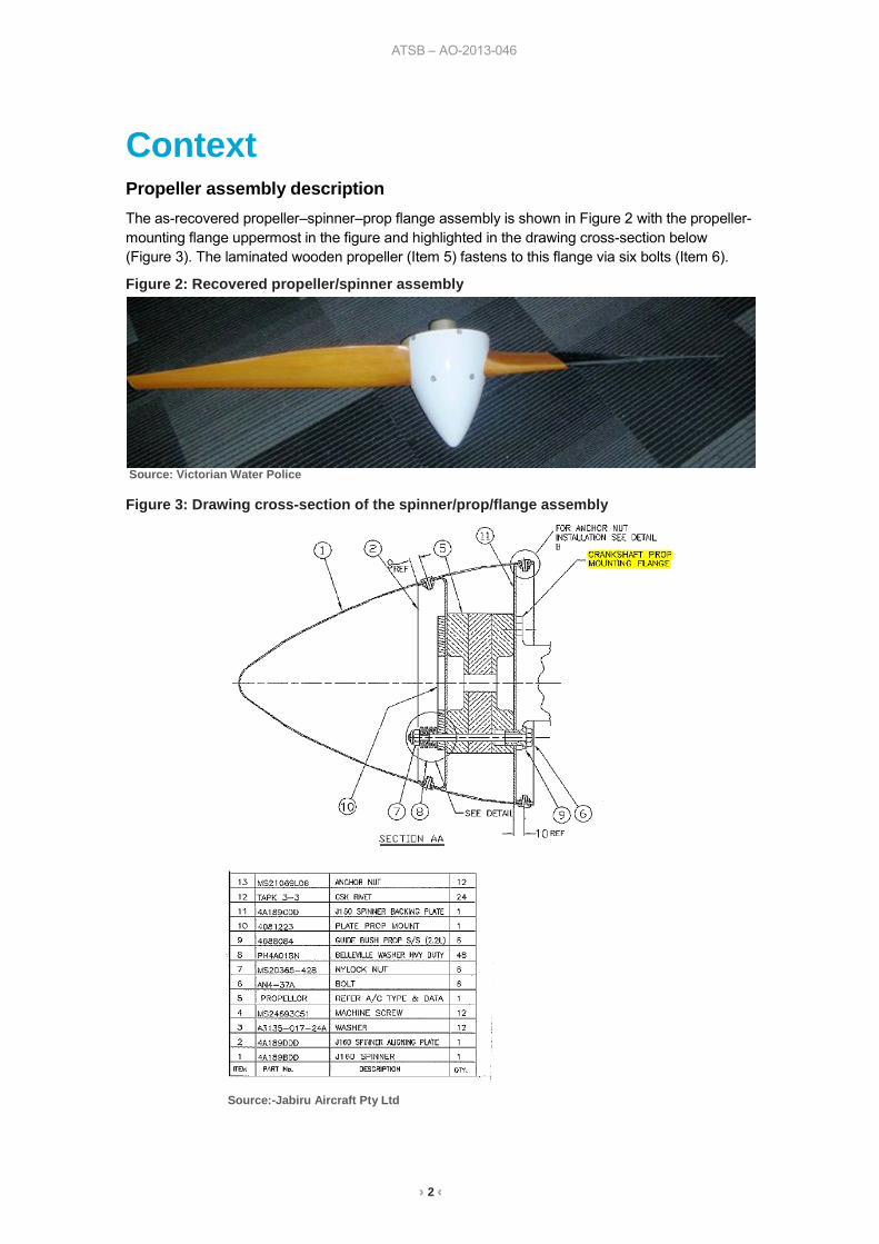
Context Propeller assembly description The as-recovered propeller–spinner–prop flange assembly is shown in Figure 2 with the propeller- mounting flange uppermost in the figure and highlighted in the drawing cross-section below (Figure 3). The laminated wooden propeller (Item 5) fastens to this flange via six bolts (Item 6).
Figure 2: Recovered propeller/spinner assembly
Source: Victorian Water Police
Figure 3: Drawing cross-section of the spinner/prop/flange assembly
Source:-Jabiru Aircraft Pty Ltd

› 3 ‹
ATSB – AO-2013-046
The propeller-mounting flange attaches to the engine crankshaft at the forward end via six 3/8” x 3/4” long, UNF socket-head cap screws (Figure 4). As can be seen in Figure 1, five of these screws on TJP had failed and one was missing.
Of note in Figure 4 is the absence of paint on the faying surfaces of the crankshaft and flange, and the presence of dowel sockets in the crankshaft (originally added for use by after-market propeller manufacturers2).
Figure 4: Exemplar attachment of prop-mounting flange onto the crankshaft
Source: Jabiru Service Bulletin JSB 022-1
Component examination After removal of the forward end of the crankshaft, the propeller assembly was separated into its principal components for individual examination. This allowed the identification stamping on the propeller’s boss to be read and decoded. This code was identified in the Aircraft Service Manual3 as an approved installation for the Jabiru 3300 engine.
Examination of the rear faying surface of the propeller flange showed the single remaining screw to be bent with four plastically-deformed threads (Figure 5). Plastic deformation of the remaining five screw bores and driven-side corners by the screws’ threads was also visible (see inset). Notable was the presence of paint and its reduced thickness in the contact areas, forming shoulders with contact-free zones (arrowed).
2 JSB 022-1 Propeller Flange Attachment. 3 Jabiru Generic Technical Manual (Aircraft Service Manual) JTM001-2.

› 4 ‹
ATSB – AO-2013-046
Figure 5: Crankshaft–prop-mounting flange faying surface; note the deformed bores (see inset) and impressed paint (arrowed)
Source: ATSB
The interior faying surface between the prop flange and the cap screws’ Belleville4 washers also had the paint reduced to predominantly bare metal in these areas (Figure 6). Paint ridges were adjacent to these six, annular areas. The undisturbed paint thickness was measured at 0.06 mm; on the reverse side (Figure 6) it was 0.05 mm in thickness. As a reference, its thickness on the crankshaft, as applied by the manufacturer, was 0.02 mm.
Figure 6: Predominantly-bare faying surfaces below washers, with adjacent paint ridges
Source: ATSB 4 Belleville (spring) washers are principally used to maintain uniform, tension load on a fastener – see NASA Fastener
Design Manual March 1990.

› 5 ‹
ATSB – AO-2013-046
The five fractured screws had corroded after immersion in salt water and required ultrasonic cleaning. Microscopic examination found that the screw directly opposite the empty, tapped hole in Figure 1 had initially failed by fatigue cracking that began at the root fillet radius, but changed to bending overstress; final failure of the remaining half of the cross-section was by ductile shear. The four remaining screws had also failed by fatigue cracking, which initiated at the thread root then proceeded across the section with final failure by overstress (Figure 7). The failure plane of these four screws was approximately level with the crankshaft faying surface, while that of the bending/shear-overload, fifth screw was approximately two threads proud of that surface (Figure 1).
Figure 7: Shallow fatigue cracking that initiated at the thread root on the right side
Source: ATSB
Microscopic examination of the screws’ exterior found remnants of a hardened, green polymer material between the male and female threads; the specified5 thread-retaining compound, Loctite 620, is green. The manufacturer’s code “YFS” was identified on all screw heads – identifying them as an approved screw per the engine manufacturer’s overhaul manual6. The entrapped sixth screw (Figures 5 and 6) was removed from its flange and sectioned through the threaded area at mid-length to allow core hardness testing. Results met the specified Hardness Rockwell C (HRC) requirements. Hardnesses of the crankshaft end were also measured and, while their converted tensile values were less than that specified in the pre-2007 drawing requirement, the values did conform to the requirements of the current crankshaft drawing that specifies production using an alloy steel to Australian Standard AS 1444-20077. The hardness of one washer was also measured and was typical of spring washers.
5 Jabiru Aircraft Engine Overhaul Manual JEM0001-4 Section 7.8.16. 6 Jabiru Aircraft Engine Overhaul Manual JEM0001-4 Section 3.10. 7 AS 1444–2007 Wrought alloy steels—Standard, hardenability (H) series and hardened and tempered to designated
mechanical properties.

› 6 ‹
ATSB – AO-2013-046
Torque testing of flange–to–crank assembly An exemplar propeller flange was assembled onto a crankshaft using manufacturer-supplied screws; the mating surfaces were clean and unoiled. Torqueing methods included both a standard torqueing practice (a single step to final torque) and an incremental torqueing i.e. nipped, then to 25 ft.lb then to 30ft.lb. It was noted during incremental torqueing that the screws did not overcome static friction and did not tighten further when transitioning from 25 to 30 ft.lb. To assess the security of the joint after torqueing, the assembly was held stationary in a press while rotation was applied to the flange using measured weights and a lever arm. The torque required for noticeable slip to occur between the flange and crank was recorded per Table 1.
Table 1: Torque at which slippage occurred w.r.t. various torqueing methods
Torqueing Method Joint Slippage Torque (measured)
Two screws torqued directly to 30ft.lb 204 Nm
Six screws torqued directly to 25ft.lb 589 Nm
Six screws torqued directly to 30ft.lb 726 Nm
Six screws torqued in steps to 30ft.lb 617 Nm
As a reference, at maximum power, the peak (instantaneous8) torque due to power pulses in the engine was calculated to be 686 Nm using the published engine data for mean torque9. This torque value lies midway between the direct and multiple-step torqueing methods to 30ft.lb.
Documentation requirements The manufacturer’s various documented technical requirements related to the painting and assembly of the propeller-mounting flange were examined and found to differ. One group of documents were either drawing-specified or contained within a safety bulletin (SB), while the other group were manuals (overhaul, maintenance or constructors). The quoted text from the various requirements is listed in Table 2.
Table 2: Documentation requirements for the flange assembly
Operation Process spec or SB requirement Manual requirement
Paint masking “Don’t paint the front face of the crank. Mask…the front (propeller mount) face of the flange…. the rear (flange to crankshaft mating faces) of the flange.”10
“Paint the propeller flange…..not paint any mating faces or faces where screw heads will bear.”11
Torqueing step frequency
“Torque all screws first to 20 lb.ft, then all to 25 ft.lb and finally all to 30 lb.ft.”12
“JSB022 must be referenced by overhaulers” and “Tighten to the torque specified in Table 9 (i.e.“40Nm (30 ft.lb)”)13
“Torque each cap screw to 30 ft.lb or 40Nm”14
Torque application As quoted above i.e. sequential steps, all in the direction of tightening
“Torque must be obtained while the nut is turning. If you stop…. the nut needs to be loosened a little and then tightened again so the torque reading is obtained while turning.”15
8 Torsional Characteristics of Piston Engine Output EPI Inc. 9 Maintenance Manual for Jabiru …..3300 Aircraft Engine JEM0002-1 p24. 10 Process Specification PSJED-13 Surface Preparation & Painting (specified by the flange drawing). 11 Overhaul Manual for Jabiru 2200 & 3300 Aircraft Engines p 99. 12 Jabiru Service Bulletin Propeller Flange Attachment JSB 022-1. 13 Overhaul Manual for Jabiru 2200 & 3300 Aircraft Engines p 147 & 148 resp. 14 Jabiru J430 Constructors Manual p66 and Maintenance Manual for….Jabiru 3300 Aircraft Engine p 19. 15 Overhaul Manual for Jabiru 2200 & 3300 Aircraft Engines JEM0001-4 p36 & Maintenance Manual for …Jabiru 3300
Aircraft Engine JEM0002-1 p39.

› 7 ‹
ATSB – AO-2013-046
Other Occurrences A check of the Australian Civil Aviation Safety Authority (CASA) Service Difficulty Report (SDR) database from 2003 to November 2013 found no incidents of propeller loss involving Jabiru J430 aircraft, although two incidents of excessive propeller vibration were reported (neither due to failed screws). The ATSB’s occurrence database contained one blade detachment reported on a Jabiru J170 (Occurrence No. 200906995). Recreational Aviation Australia (RA-Aus) reported a propeller departure from a Jabiru J160c in September 2012. The NTSB reported that their database totalled nine separations in the United States and other countries. The latest separation in 2013 had resulted from sudden engine seizure; the inertia of the propeller being sufficient to shear the cap screws by overstress.

› 8 ‹
ATSB – AO-2013-046
Safety analysis Occurrence flight The pilot correctly followed the manufacturer’s procedures for Other Emergencies in its Pilot’s Operating Handbook, by maintaining control of the aircraft and electing to discontinue the flight soon after the onset of vibration (before the propeller separated).
Propeller-mounting flange screw failures During engine operation, relative movement had occurred between the propeller-mounting flange and crankshaft. This was evidenced by screw thread impressions in the mounting flange’s cap screw bores, the resultant flattening of the screw thread top lands and burrs on the driven-side of the screw bore corners. Torsional load tests on an exemplar assembly showed that such mating-part slippage was possible at the levels of screw tension specified by the manufacturer’s directions. The result of this movement was to apply a combination bending–bearing load to the screws’ threads. That load was sufficient to initiate fatigue cracking at the screw thread root fillet radii. As the cracking developed, its rate of propagation increased, with the loss of the screws’ integrity leading to the worsening vibrations experienced by the pilot. Final overstress failure of the screws led directly to the loss of the propeller assembly.
The absence of dowel pins in the sockets at the end of the crankshaft (see Figure 1) and absence of mating holes in the prop flange (Figure 6) were noted. At the time that this assembly was manufactured, there was no requirement for the installation of interference-fit dowels - these were introduced to the flange/crankshaft joint in July 2011(at engine Serial Number 2446). Positive- location dowels serve directly to limit any rotational slippage that may occur within the flange joint – preventing the assembly from bearing against the fastening screws and producing the fatigue cracking as sustained by the assembly from TJP.
Insufficient joint clamping Two issues with the assembled flange–crankshaft joint were found during testing and examination. Firstly, during slip torque testing, it was confirmed (as expected) that there was a direct correlation between torque applied to the screws and the resultant slip torque for the flange–crankshaft assembly. It was also found that the Service Bulletin16-specified, multi-step method of torqueing the cap screws resulted in reduced assembly slip torque than that achieved with a direct, one-step torqueing procedure. That procedure is specified for initial engine assembly, replacement of the standard prop flange17, engine maintenance and engine overhaul (see Table 2). The slip torque value obtained from the multi-step procedure was both less than the engine’s instantaneous torque at maximum power and was around 85% of that achieved using a single-step torqueing method. These differences relate to the doubling of friction when movement ceases during fastener torqueing18 - significant torque is required to overcome static friction when attempting to rotate a stationary fastener.
16 Propeller Flange Attachment Service Bulletin JSB 022-1, issued 28th July 2008 17 Jabiru J430 Constructors Manual 18 Machinery’s Handbook 27th Edition p 158 Friction, Overhaul Manual for Jabiru 2200 & 3300 Aircraft Engines JEM 0001-
4 Issue 4 p 38 and Maintenance Manual for… Jabiru 3300 Aircraft Engine JEM0002-1 page 39

› 9 ‹
ATSB – AO-2013-046
The second key issue was the discovery of paint on the prop-flange–crank joint surfaces (Figure 5) and the cap screw washer–inner flange surface (Figure 6). This was in contradiction of some drawing, process specification and manual requirements19. The presence of paint or other soft materials on clamping surfaces can result in joint relaxation20 and an elevated probability of the screws failing by fatigue cracking21. Visually and microscopically-detected ridges in the paint on both surfaces confirmed that relaxation had occurred within the joint from TJP.
To avoid creep in joints with known compressible materials between the faying surfaces, some engineering specifications recommend that fasteners, firstly, be fully torqued, followed by a dwell period to allow compression, after which the joint is undone and the fasteners retightened. Such a procedure was not specified in the manufacturer’s safety bulletin for propeller-mounting flange installation.
Documentation anomalies Differences in requirements between the manufacturer’s documents were found in the areas relating to the non-painting of each faying surface in the joint, the torqueing procedure of the propeller flange–crankshaft screws (multi- or single-step) and the referencing of dynamic torqueing requirements for fasteners (see Table 2). Such variability, depending on which document was referenced by maintainers, could have contributed to the assembly of the propeller flange joint in a manner that predisposed it to movement and subsequent failure.
.
19 Drawing (Flange – Prop Mount Extended 4662084-6) -specified Process Specification PSJED-13 Surface Preparation &
Painting and Overhaul Manual for Jabiru 2200 * 3300 Aircraft Engines JEM 0001-4 Issue 4 page 99. 20 Joint Relaxation in Fastened Joints; Mountz technical article. 21 ASM Handbook Volume 19 Fatigue and Fracture page 289 Effect of Preload.

› 10 ‹
ATSB – AO-2013-046
Findings From the evidence available, the following findings are made with respect to the in-flight loss of the propeller from a Jabiru Aircraft Pty Ltd J430 (registered VH-TJP), that occurred north of French Island in Western Port Bay, Victoria on 8 March 2013. These findings should not be read as apportioning blame or liability to any particular organisation or individual.
Safety issues, or system problems, are highlighted in bold to emphasise their importance. A safety issue is an event or condition that increases safety risk and (a) can reasonably be regarded as having the potential to adversely affect the safety of future operations and (b) is a characteristic of an organisation or a system, rather than a characteristic of a specific individual or characteristic of an operating environment at a specific point in time..
Contributing factors • Jabiru engines manufactured before July 2011 have reduced strength and reliability of
the crankshaft/propeller flange joint, compared with the later design that incorporated positive location dowel pins. [Safety Issue]
• The engine manufacturer’s specified procedure for assembling and torqueing of the crankshaft/propeller flange fasteners was ineffective in ensuring resistance against subsequent joint movement in service. [Safety Issue]
• Movement in the propeller-mounting flange–crankshaft joint resulted from the ineffective torqueing procedure and joint relaxation stemming from the presence of elastically-soft material (paint) between the joint surfaces.
• Joint movement and the absence of locating dowels placed the screws under bending loads – directly contributing to the initiation and propagation of fatigue cracking and propeller flange separation.
• The engine manufacturer’s documents with respect to the propeller mounting flange were technically inconsistent with regard to painting and torqueing procedures. [Safety Issue]
Other findings • The pilot correctly followed the manufacturer’s procedures for Other Emergencies in its Pilot’s
Operating Handbook, by maintaining control of the aircraft and electing to discontinue the flight soon after the onset of vibration (before the propeller separated).

› 11 ‹
ATSB – AO-2013-046
Safety issues and actions Depending on the level of risk of the safety issue, the extent of corrective action taken by the relevant organisation or the desirability of directing a broad safety message to the aviation industry, the ATSB may issue safety recommendations or safety advisory notices as part of the final report.
Engines with un-doweled crankshaft–propeller flange joints Number: AO-2013-046-SI-01
Issue owner: Jabiru Aircraft Pty Ltd
Operation affected: Aviation: General Aviation
Who it affects: All owners and operators of Jabiru J230 & J430 aircraft with an engine number before 33A2446 i.e. 2,445 pre-July 2011 engines
Safety issue description: Jabiru engines manufactured before July 2011 have reduced strength and reliability of the crankshaft/propeller flange joint, compared with the later design that incorporated positive location dowel pins.
Response to safety issue and/or pro-active safety action taken by: Jabiru Aircraft Pty Ltd The current revision of the Jabiru Engine Overhaul Manual (document JEM0001-6) now includes a strong recommendation that owners update their engines during the next full overhaul or bulk strip, to include propeller flange dowels between the crankshaft and propeller flange - see Appendix A
Action number: AO-2013-046-NSA-014
ATSB comment/action in response:
The ATSB is satisfied that the action to be taken by Jabiru should reduce the risk of design deficiencies with earlier (pre-engine SN 2446) crankshaft/ propeller flange assemblies.
Current status of the safety issue: Issue status: Adequately addressed
Justification: The amendments should ensure the increased reliability of the propeller flange/crankshaft joint and the reduced likelihood of propeller loss due to joint fastener failure.
Insufficient joint clamping Number: AO-2013-046-SI-02
Issue owner: Jabiru Aircraft Pty Ltd
Operation affected: Aviation: General Aviation
Who it affects: All owners and operators of Jabiru J230 & J430 aircraft
Safety issue description: The manufacturer’s specified procedure for assembling and torqueing of the crankshaft/propeller flange fasteners was ineffective in ensuring resistance against subsequent joint movement in service.

› 12 ‹
ATSB – AO-2013-046
Response to safety issue and/or pro-active safety action taken by: Jabiru Aircraft Pty Ltd The manufacturer has issued a revised Propeller Flange Attachment Service Bulletin. It no longer specifies the multi-step torqueing procedure, instead referring to the correct procedure in the Engine Overhaul Manual i.e. single-step torqueing.
An additional requirement has been introduced for mounting surfaces to be free from paint, thread-locking compound or other contaminants before assembly. The relevant painting process specification now requires that all three faying surfaces of the flange be masked plus an illustrative diagram accompanies the text.
Action number: AO-2013-046-NSA-015
Current status of the safety issue: Issue status: Adequately addressed.
Justification: The documentary changes should ensure the increased reliability of the propeller flange/crankshaft joint and the reduced likelihood of propeller loss due to joint fastener failure.
Documentation anomalies Number: AO-2013-046-SI-03
Issue owner: Jabiru Aircraft Pty Ltd
Operation affected: Aviation: General Aviation
Who it affects: All owners and operators of Jabiru J230 & J430 aircraft
Safety issue description: The engine manufacturer’s documents with respect to the propeller mounting flange were technically inconsistent with regard to painting and torqueing procedures.
Response to safety issue and/or pro-active safety action taken by: Jabiru Aircraft Pty Ltd On the matter of avoiding paint on all the propeller-mounting flange’s faying surfaces – additional text has been included within the engine overhaul manual to emphasise and strengthen the requirement. Additionally, the latest revision of the process specification, covering surface preparation and painting, unambiguously specifies the manuals’ requirement for nil paint below the cap screw washers and the crank and propeller faying surfaces. On the subject of consistency for the torqueing procedure, this has been amended in both relevant manuals to solely specify the one-step, dynamic torqueing process.
Action number: AO-2013-046-NSA-016
Current status of the safety issue: Issue status: Adequately addressed.
Justification: The documentary changes should ensure the increased reliability of the propeller flange/crankshaft joint and the reduced likelihood of propeller loss due to joint fastener failure.

› 13 ‹
ATSB – AO-2013-046
General details Occurrence details
Date and time: 8 March 2013 16:15 EDST
Occurrence category: Accident
Primary occurrence type: Technical - Powerplant / propulsion - Propellor / rotor malfunction
Location: North of French Island Western Port Bay, Victoria
Latitude: 38° 16.42’ S Longitude: 145° 12.98’ E
Aircraft details Manufacturer and model: Jabiru Aircraft Pty Ltd J430
Registration: VH-TJP
Operator: Andrew Price
Serial number: 567
Type of operation: Private
Persons on board: Crew – 1 Passengers – nil
Injuries: Crew – nil Passengers – not applicable
Damage: Substantial
› 14 ‹
ATSB – AO-2013-046
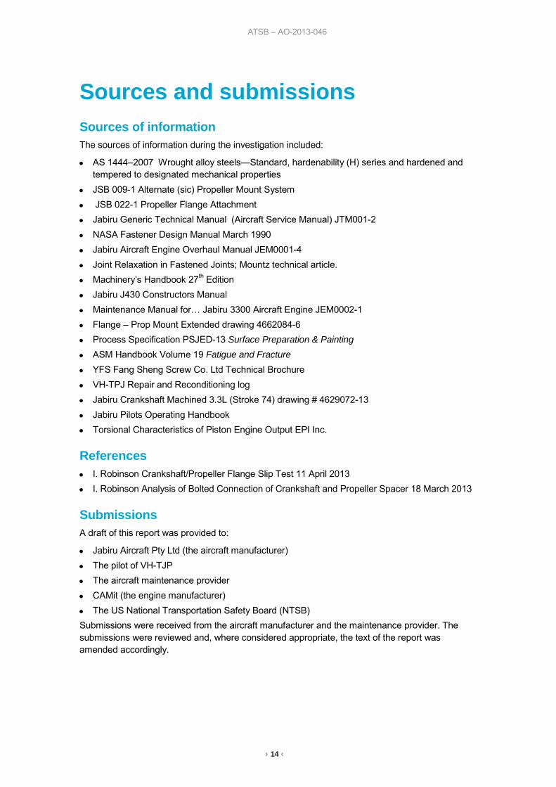
Sources and submissions Sources of information The sources of information during the investigation included:
• AS 1444–2007 Wrought alloy steels—Standard, hardenability (H) series and hardened and tempered to designated mechanical properties
• JSB 009-1 Alternate (sic) Propeller Mount System
• JSB 022-1 Propeller Flange Attachment • Jabiru Generic Technical Manual (Aircraft Service Manual) JTM001-2
• NASA Fastener Design Manual March 1990
• Jabiru Aircraft Engine Overhaul Manual JEM0001-4
• Joint Relaxation in Fastened Joints; Mountz technical article. • Machinery’s Handbook 27th Edition
• Jabiru J430 Constructors Manual
• Maintenance Manual for… Jabiru 3300 Aircraft Engine JEM0002-1 • Flange – Prop Mount Extended drawing 4662084-6 • Process Specification PSJED-13 Surface Preparation & Painting
• ASM Handbook Volume 19 Fatigue and Fracture
• YFS Fang Sheng Screw Co. Ltd Technical Brochure
• VH-TPJ Repair and Reconditioning log
• Jabiru Crankshaft Machined 3.3L (Stroke 74) drawing # 4629072-13
• Jabiru Pilots Operating Handbook • Torsional Characteristics of Piston Engine Output EPI Inc.
References • I. Robinson Crankshaft/Propeller Flange Slip Test 11 April 2013 • I. Robinson Analysis of Bolted Connection of Crankshaft and Propeller Spacer 18 March 2013
Submissions A draft of this report was provided to:
• Jabiru Aircraft Pty Ltd (the aircraft manufacturer) • The pilot of VH-TJP • The aircraft maintenance provider • CAMit (the engine manufacturer) • The US National Transportation Safety Board (NTSB) Submissions were received from the aircraft manufacturer and the maintenance provider. The submissions were reviewed and, where considered appropriate, the text of the report was amended accordingly.

› 15 ‹
ATSB – AO-2013-046
Appendix A

› 16 ‹
ATSB – AO-2013-046

› 17 ‹
ATSB – AO-2013-046
Australian Transport Safety Bureau The Australian Transport Safety Bureau (ATSB) is an independent Commonwealth Government statutory agency. The ATSB is governed by a Commission and is entirely separate from transport regulators, policy makers and service providers. The ATSB’s function is to improve safety and public confidence in the aviation, marine and rail modes of transport through excellence in: independent investigation of transport accidents and other safety occurrences; safety data recording, analysis and research; fostering safety awareness, knowledge and action.
The ATSB is responsible for investigating accidents and other transport safety matters involving civil aviation, marine and rail operations in Australia that fall within Commonwealth jurisdiction, as well as participating in overseas investigations involving Australian registered aircraft and ships. A primary concern is the safety of commercial transport, with particular regard to fare-paying passenger operations.
The ATSB performs its functions in accordance with the provisions of the Transport Safety Investigation Act 2003 and Regulations and, where applicable, relevant international agreements.
Purpose of safety investigations The object of a safety investigation is to identify and reduce safety-related risk. ATSB investigations determine and communicate the factors related to the transport safety matter being investigated.
It is not a function of the ATSB to apportion blame or determine liability. At the same time, an investigation report must include factual material of sufficient weight to support the analysis and findings. At all times the ATSB endeavours to balance the use of material that could imply adverse comment with the need to properly explain what happened, and why, in a fair and unbiased manner.
Developing safety action Central to the ATSB’s investigation of transport safety matters is the early identification of safety issues in the transport environment. The ATSB prefers to encourage the relevant organisation(s) to initiate proactive safety action that addresses safety issues. Nevertheless, the ATSB may use its power to make a formal safety recommendation either during or at the end of an investigation, depending on the level of risk associated with a safety issue and the extent of corrective action undertaken by the relevant organisation.
When safety recommendations are issued, they focus on clearly describing the safety issue of concern, rather than providing instructions or opinions on a preferred method of corrective action. As with equivalent overseas organisations, the ATSB has no power to enforce the implementation of its recommendations. It is a matter for the body to which an ATSB recommendation is directed to assess the costs and benefits of any particular means of addressing a safety issue.
When the ATSB issues a safety recommendation to a person, organisation or agency, they must provide a written response within 90 days. That response must indicate whether they accept the recommendation, any reasons for not accepting part or all of the recommendation, and details of any proposed safety action to give effect to the recommendation.
The ATSB can also issue safety advisory notices suggesting that an organisation or an industry sector consider a safety issue and take action where it believes it appropriate. There is no requirement for a formal response to an advisory notice, although the ATSB will publish any response it receives.


AT
SB
Transp
ort S
afety Rep
ort
Aviation O
ccurrence Investigation
Propeller loss involving Jabiru J430, V
H-TJP
N
orth of French Island, Victoria, 8 M
arch 2013
AO
-2013-046
Final – 19 August 2014
Investigatio
n
Australian Transport Safety Bureau
Enquiries 1800 020 616Notifications 1800 011 034REPCON 1800 011 034Web www.atsb.gov.auTwitter @ATSBinfoEmail [email protected]